Omron IPC Machine Controller Industrial Panel PC / Industrial Box PC. Software User’s Manual (Industrial PC Platform NY-series) - page 1
Industrial PC Platform
NY-series
IPC Machine Controller
Industrial Panel PC / Industrial Box PC
Software
User’s Manual
NY532-1500
NY532-1400
NY532-1300
NY532-5400
NY512-1500
NY512-1400
NY512-1300
Industrial Panel PC
Industrial Box PC
W558-E1-05
Introduction
Introduction
Thank you for purchasing an NY-series IPC Machine Controller Industrial Panel PC / Industrial Box PC.
This manual provides a collective term of Industrial Panel PC and Industrial Box PC which are applica-
ble products as the NY-series Industrial PC. This manual also provides the range of devices that are
directly controlled by the Controller functions embedded the Real-Time OS in the NY-series Industrial
PC as the Controller.
This manual contains information that is necessary to use the NY-series Controller. Please read this
manual and make sure you understand the functionality and performance of the NY-series Controller
before you attempt to use it in a control system.
Keep this manual in a safe place where it will be available for reference during operation.
Intended Audience
This manual is intended for the following personnel, who must also have knowledge of electrical sys-
tems (an electrical engineer or the equivalent).
• Personnel in charge of introducing FA systems.
• Personnel in charge of designing FA systems.
• Personnel in charge of installing and maintaining FA systems.
• Personnel in charge of managing FA systems and facilities.
For programming, this manual is intended for personnel who understand the programming language
specifications in international standard IEC 61131-3 or Japanese standard JIS B 3503.
Applicable Products
This manual covers the following products.
• NY-series IPC Machine Controller Industrial Panel PC
• NY532-15
• NY532-14
• NY532-13
• NY532-5400
• NY-series IPC Machine Controller Industrial Box PC
• NY512-15
• NY512-14
• NY512-13
Part of the specifications and restrictions for the Industrial PC are given in other manuals. Refer to Rel-
evant Manuals on page 2 and Related Manuals on page 35.
1
Relevant Manuals
Relevant Manuals
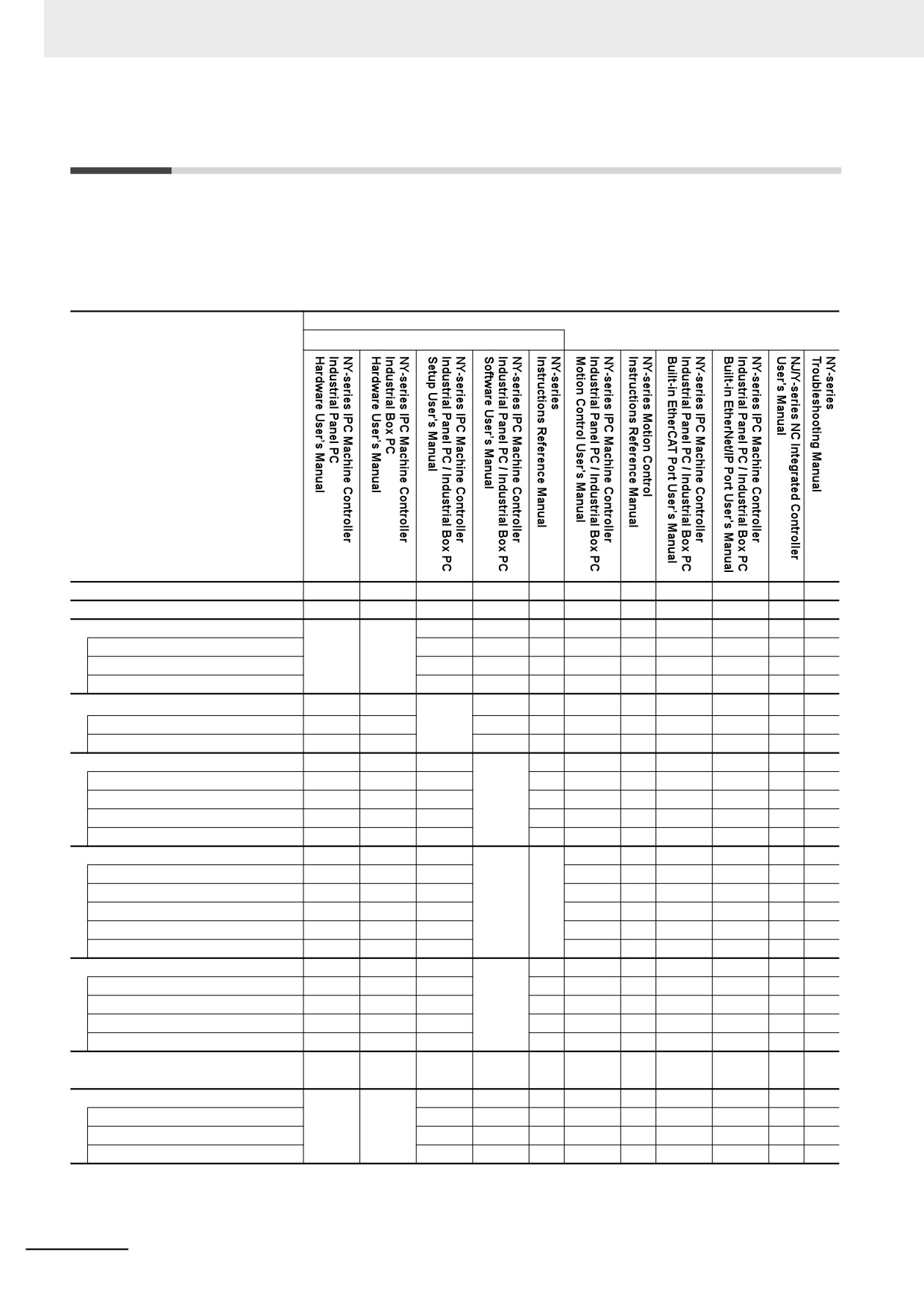
The following table provides the relevant manuals for the NY-series Controller.
Read all of the manuals that are relevant to your system configuration and application before you use
the NY-series Controller.
Most operations are performed from the Sysmac Studio Automation Software. Refer to the Sysmac Stu-
dio Version 1 Operation Manual (Cat. No. W504) for information on the Sysmac Studio.
Manual
Basic information
Purpose of use
Introduction to NY-series Panel PCs
{
Introduction to NY-series Box PCs
{
Setting devices and hardware
Using motion control
{
{
{
Using EtherCAT
{
Using EtherNet/IP
{
Making setup*1
Making initial settings
{
Preparing to use Controllers
Software settings
Using motion control
{
Using EtherCAT
{
{
Using EtherNet/IP
{
Using numerical control
{
Writing the user program
Using motion control
{
{
Using EtherCAT
{
{
{
Using EtherNet/IP
{
Using numerical control
{
Programming error processing
{
Testing operation and debugging
Using motion control
{
Using EtherCAT
{
{
Using EtherNet/IP
{
Using numerical control
{
Learning about error management and
{
corrections*2
Maintenance
Using motion control
{
{
{
Using EtherCAT
{
Using EtherNet/IP
{
*1
Refer to the NY-series Industrial Panel PC / Industrial Box PC Setup User's Manual (Cat. No. W568) for how to set up and
how to use the utilities on Windows.
*2
Refer to the NY-series Troubleshooting Manual (Cat. No. W564) for the error management concepts and the error items.
2
Manual Structure
Manual Structure
Some of the descriptions of functions in this manual are common to NJ/NX-series. Therefore, note the
following conditions.
• The same function names are used for the common functions of the NJ/NX/NY-series. If the term
“CPU Unit” is included in the function names, such as the CPU Unit names, CPU Unit write protection
and other functions, it indicates the “Controller” in the NY-series.
• The “CPU Unit” that is described in a list of function specifications in this manual also indicates the
“Controller” in the NY-series.
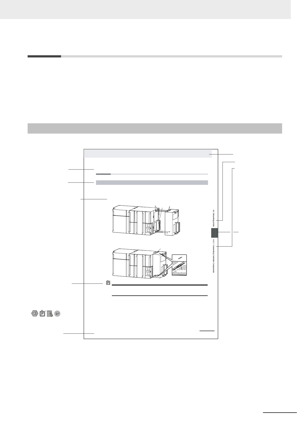
Page Structure
The following page structure is used in this manual.
4 Installation and Wiring
Level 1 heading
Level 2 heading
Level 2 heading
4-3
Mounting Units
Level 3 heading
Gives the current
Level 3 heading
4-3-1
Connecting Controller Components
headings.
The Units that make up an NY-series Controller can be connected simply by pressing the Units together
and locking the sliders by moving them toward the back of the Units. The End Cover is connected in the
same way to the Unit on the far right side of the Controller.
A step in a procedure
1 Join the Units so that the connectors fit exactly.
Hook
Hook holes
Indicates a procedure.
Connector
4
Page tab
Gives the number
2 The yellow sliders at the top and bottom of each Unit lock the Units together. Move the sliders
toward the back of the Units as shown below until they click into place.
of the main section.
Move the sliders toward the back
until they lock into place.
Lock
Release
Slider
Precautions for Correct Use
Special information
The sliders on the tops and bottoms of the Power Supply Unit, CPU Unit, I/O Units, Special I/O
Units, and CPU Bus Units must be completely locked (until they click into place) after connecting
Icons indicate
the adjacent Unit connectors.
precautions, additional
information, or reference
information.
NY-series Industrial Box PC Hardware User’s Manual (W556)
4-9
Manual name
This illustration is provided only as a sample. It may not literally appear in this manual.
3
Manual Structure
Special Information
Special information in this manual is classified as follows:
Precautions for Safe Use
Precautions on what to do and what not to do to ensure safe usage of the product.
Precautions for Correct Use
Precautions on what to do and what not to do to ensure proper operation and performance.
Additional Information
Additional information to read as required.
This information is provided to increase understanding or make operation easier.
Version Information
Information on differences in specifications and functionality for Controller with different unit versions
and for different versions of the Sysmac Studio is given.
Note References are provided to more detailed or related information.
Precaution on Terminology
In this manual, “download” refers to transferring data from the Sysmac Studio to the physical Controller
and “upload” refers to transferring data from the physical Controller to the Sysmac Studio.
For the Sysmac Studio, synchronization is used to both upload and download data. Here, “synchronize”
means to automatically compare the data for the Sysmac Studio on the computer with the data in the
physical Controller and transfer the data in the direction that is specified by the user.
4
Sections in this Manual
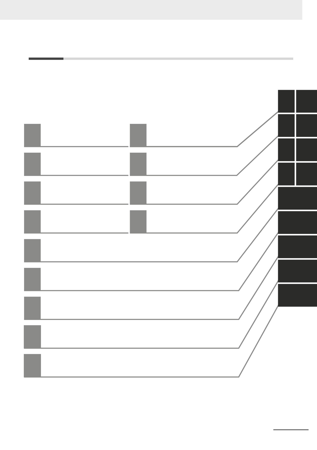
Sections in this Manual
1
10
2
11
Introduction to
Communications Setup
1
10
NY-series Controllers
3
A
NY-series Controller
Example of Actual
2
11
Operation
Application Procedures
4
I
I/O Ports, Slave
Configuration, and
Appendices
3
A
Unit Configuration
5
Index
4
Controller Setup
I
6
7
5
Designing Tasks
8
6
Programming
9
Checking Operation and
7
Actual Operation
Controller Functions
8
Backup Functions
9
5
CONTENTS
CONTENTS
Introduction
1
Relevant Manuals
2
Manual Structure
3
Sections in this Manual
5
Terms and Conditions Agreement
14
Safety Precautions
16
Precautions for Safe Use
22
Precautions for Correct Use
28
Regulations and Standards
32
Versions
33
Related Manuals
35
Terminology
38
Revision History
42
Section 1
Introduction to NY-series Controllers
1-1
The NY-series Controllers
1-2
1-1-1
Features
1-3
1-1-2
Introduction to the System Configurations
1-5
1-2
Main Specifications
1-7
1-3
Product Model Numbers
1-9
1-4
Overall Operating Procedure for the NY-series Controller
1-10
1-4-1
Overall Procedure
1-10
1-4-2
Procedure Details
1-11
Section 2
NY-series Controller Operation
2-1
Overview of NY-series Controller Operation
2-2
2-1-1
Introduction to NY-series Controller
2-2
2-1-2
Overview of Operation According to NY-series Controller Status
2-3
2-2
Software
2-4
2-2-1
Software Configuration
2-4
2-2-2
Operation of Software
2-5
2-3
Accessing I/O
2-10
2-3-1
Types of Variables
2-10
2-3-2
Accessing I/O with Variables
2-13
2-4
Sequence Control and Motion Control
2-16
2-4-1
Overview of Control
2-16
2-4-2
Sequence Control System
2-18
6
CONTENTS
2-4-3
Motion Control System
2-19
2-4-4
Synchronizing Sequence Control and Motion Control
2-20
2-5
Overview of Controller Data
2-21
2-6
Operation for Controller Status
2-22
2-6-1
Controller Status
2-22
2-6-2
Operation for Controller Status
2-24
2-6-3
Operating Modes
2-25
2-7
Monitoring and Changing Windows Status
2-28
2-7-1
Windows Status
2-28
2-7-2
Monitoring Windows Status
2-28
2-7-3
Changing Windows Status
2-29
2-7-4
Changes in Windows Status
2-29
2-8
Shutdown
2-30
2-8-1
Processing When Power Is Interrupted or Power Supply Button Is Pressed
2-31
2-8-2
Settings of Shutdown
2-32
2-8-3
Contents of Shutdown
2-33
2-9
Resetting the Controller
2-36
Section 3
I/O Ports, Slave Configuration, and Unit Configuration
3-1
Procedure to Create the Slave and Unit Configurations
3-2
3-2
Creating the EtherCAT Slave Configuration
3-4
3-3
I/O Ports and Device Variables
3-5
3-3-1
I/O Ports
3-5
3-3-2
I/O Port Names
3-6
3-3-3
Device Variables
3-6
3-4
Allocating Variables to Units
3-8
3-4-1
Procedure to Assign Variables to Units
3-8
3-4-2
Using Variables Assigned to Units
3-9
3-5
Creating the Axes and Assigning Them to the Servo Drives/Encoder Input Slaves
3-11
3-5-1
Introduction
3-11
3-5-2
Axis Variables and Axes Group Variables
3-12
3-5-3
Creating and Using Axes and Axis Variables
3-14
Section 4
Controller Setup
4-1
Overview of the Controller Setup
4-2
4-2
Initial Settings for the PLC Function Module
4-4
4-2-1
Introduction
4-4
4-2-2
Controller Setup
4-4
4-2-3
Task Settings
4-7
4-3
Initial Settings for the Motion Control Function Module
4-12
4-3-1
Introduction
4-12
4-3-2
Setting Methods
4-13
4-4
Initial Settings for the EtherCAT Master Function Module
4-14
4-5
Initial Settings for the EtherNet/IP Function Module
4-15
Section 5
Designing Tasks
5-1
Overview of Task Designing Procedure
5-2
5-2
Overview of Tasks
5-4
5-2-1
Tasks
5-4
7
CONTENTS
5-2-2
Instructions Related to Tasks
5-6
5-2-3
System-defined Variables Related to Tasks
5-6
5-3
Specifications and Basic Operation of Tasks for NY-series Controllers
5-8
5-3-1
Specifications of Tasks for NY-series Controllers
5-8
5-3-2
Guidelines for Separating Tasks for NY-series Controllers
5-9
5-3-3
Basic Operation of Tasks for NY-series Controllers
5-10
5-3-4
Event Task Execution Conditions for NY-series Controllers
5-16
5-3-5
Event Task Execution Timing for NY-series Controllers
5-21
5-3-6
Operation When Execution Condition Is Met Again Before Execution of the Event Task Is
Completed
5-26
5-4
Tag Data Link Service and System Services
5-27
5-4-1
Execution Priorities and Execution Orders of the Tag Data Link Service and System Services
..................................................................................................................................................5-28
5-4-2
Processing Performed in and Execution Timing of the Tag Data Link Service
5-30
5-4-3
Processing Performed in and Execution Timing of the System Services
5-32
5-5
Assignment and Settings Related to Tasks
5-33
5-5-1
Assigning I/O Refreshing to Tasks
5-33
5-5-2
Assigning Tasks to Programs
5-39
5-5-3
Parameters for Primary Periodic Task and Periodic Tasks
5-40
5-6
Ensuring Concurrency of Variable Values
5-42
5-6-1
Ensuring Concurrency of Variable Values between Tasks
5-42
5-6-2
Variable Access from Outside the Controller
5-49
5-7
Errors Related to Tasks
5-53
5-8
Monitoring Task Execution Status and Task Execution Times
5-55
5-9
Task Design Methods and I/O Response Times
5-59
5-9-1
Checking the Task Execution Time
5-59
5-9-2
Examples of Task Design
5-60
5-9-3
System Input and Output Response Times
5-61
Section 6
Programming
6-1
Overview of Programming Procedures
6-3
6-2
POUs (Program Organization Units)
6-5
6-2-1
What Are POUs?
6-5
6-2-2
Overview of the Three Types of POUs
6-6
6-2-3
Differences between Programs, Functions, and Function Blocks
6-7
6-2-4
Details on Programs
6-7
6-2-5
Details on Function Blocks
6-8
6-2-6
Details on Functions
6-17
6-2-7
Operation That Applies to Both Functions and Function Blocks
6-22
6-2-8
POU Restrictions
6-24
6-3
Variables
6-27
6-3-1
Variables
6-27
6-3-2
Types of Variables
6-27
6-3-3
Types of User-defined Variables in Respect to POUs
6-27
6-3-4
Attributes of Variables
6-28
6-3-5
Data Types
6-30
6-3-6
Derivative Data Types
6-41
6-3-7
Array Specifications and Range Specifications for Data Types
6-51
6-3-8
Variable Attributes
6-61
6-3-9
Changes to Variables for Status Changes
6-68
6-3-10
Function Block Instances
6-83
6-3-11
Monitoring Variable Values
6-83
6-3-12
Restrictions on Variable Names and Other Program-related Names
6-84
6-4
Constants (Literals)
6-86
6-4-1
Constants
6-86
6-4-2
Notation for Different Data Types
6-86
8
CONTENTS
6-5
Programming Languages
6-91
6-5-1
Programming Languages
6-91
6-5-2
Ladder Diagram Language
6-91
6-5-3
Structured Text Language
6-97
6-6
Instructions
6-134
6-6-1
Instructions
6-134
6-6-2
Basic Understanding of Instructions
6-134
6-6-3
Instruction Errors
6-137
6-7
Namespaces
6-142
6-7-1
Namespaces
6-142
6-7-2
Namespace Specifications
6-143
6-7-3
Procedure for Using Namespaces
6-146
6-8
Libraries
6-147
6-8-1
Introduction to Libraries
6-147
6-8-2
Specifications of Libraries
6-148
6-8-3
Library Object Specifications
6-149
6-8-4
Procedure to Use Libraries
6-150
6-9
Programming Precautions
6-151
6-9-1
Array Specifications for Input Variables, Output Variables, In-Out Variables
6-151
6-9-2
Structure Variables for Input Variables, Output Variables, In-Out Variables
6-151
6-9-3
Master Control
6-152
Section 7
Checking Operation and Actual Operation
7-1
Overview of Steps in Checking Operation and Actual Operation
7-2
7-2
Offline Debugging
7-3
7-2-1
Features of Simulation
7-3
7-2-2
Simulation Execution
7-3
7-2-3
Setting Up Simulations
7-6
7-3
Checking Operation on the Actual System and Actual Operation
7-8
7-3-1
Procedures
7-8
7-3-2
Downloading the Project
7-9
7-3-3
Checking I/O Wiring
7-9
7-3-4
MC Test Run
7-9
7-3-5
Checking the Operation of the User Program
7-10
7-3-6
Starting Actual Operation
7-10
Section 8
Controller Functions
8-1
Data Management, Clock, and Operating Functions
8-3
8-1-1
Clearing All Memory
8-3
8-1-2
Clock
8-3
8-2
SD Memory Card Operations
8-6
8-2-1
SD Memory Card Operations
8-6
8-2-2
Setting Shared Folders and Virtual SD Memory Cards
8-7
8-2-3
Recognizing and Canceling Recognitions of Virtual SD Memory Cards
8-7
8-2-4
Specifications of Shared Folders and Files for Windows
8-10
8-2-5
SD Memory Card Instructions
8-12
8-2-6
FTP Client Communications Instructions
8-12
8-2-7
FTP Server
8-13
8-2-8
File Operations from the Sysmac Studio
8-13
8-2-9
List of System-defined Variables Related to SD Memory Cards
8-14
8-2-10
Exclusive Control of File Access in Virtual SD Memory Cards
8-15
8-3
Security
8-16
8-3-1
Authentication of User Program Execution IDs
8-17
8-3-2
User Program Transfer with No Restoration Information
8-20
8-3-3
Overall Project File Protection
8-21
9
CONTENTS
8-3-4
Data Protection
8-22
8-3-5
Operation Authority Verification
8-24
8-3-6
CPU Unit Write Protection
8-26
8-3-7
CPU Unit Names and Serial IDs
8-27
8-4
Debugging
8-29
8-4-1
Forced Refreshing
8-29
8-4-2
Changing Present Values
8-33
8-4-3
Online Editing
8-35
8-4-4
Data Tracing
8-37
8-4-5
Differential Monitoring
8-43
8-5
Event Logs
8-49
8-5-1
Introduction
8-49
8-5-2
Detailed Information on Event Logs
8-50
8-5-3
Controller Events (Controller Errors and Information)
8-55
8-5-4
User-defined Events (User-defined Errors and Information)
8-56
8-6
Changing Event Levels
8-63
8-6-1
Applications of Changing Event Levels
8-63
8-6-2
Events for Which the Event Level Can Be Changed
8-63
8-6-3
Procedure to Change an Event Level
8-64
Section 9
Backup Functions
9-1
The Backup Functions
9-3
9-1-1
Applications of Backup Functions
9-3
9-1-2
Data That Is Backed Up
9-4
9-1-3
Types of Backup Functions
9-5
9-1-4
Relation between the Different Types of Backup Functions and Data Groups
9-7
9-1-5
Applicable Range of the Backup Functions
9-8
9-2
SD Memory Card Backups
9-10
9-2-1
Backup (Controller to Virtual SD Memory Card)
9-11
9-2-2
Verify (between Controller and Virtual SD Memory Card)
9-15
9-3
Disabling Backups to SD Memory Cards
9-19
9-4
Sysmac Studio Controller Backups
9-20
9-4-1
Backup (Controller to Computer)
9-21
9-4-2
Restore (Computer to Controller)
9-22
9-4-3
Verify (between Controller and Computer)
9-23
9-5
Importing and Exporting Sysmac Studio Backup File Data
9-24
9-6
Sysmac Studio Variable and Memory Backup Functions
9-25
9-6-1
Applicable Data for Sysmac Studio Variable and Memory Backup Functions
9-25
9-6-2
Using Sysmac Studio Variable and Memory Backup Functions
9-25
9-6-3
Compatibility between NY-series Controller Models
9-25
9-7
Backup Functions When EtherCAT Slaves Are Connected
9-26
9-7-1
Backed Up EtherCAT Slave Data
9-26
9-7-2
Backup Support Depending on the Controller Status
9-27
9-7-3
Conditions for Restoring EtherCAT Slave Data
9-28
9-7-4
EtherCAT Slaves for Which You Can Back Up Data
9-29
9-8
Backup Functions When EtherCAT Slave Terminals Are Connected
9-31
9-8-1
Backing Up Data in an EtherCAT Slave Terminal
9-31
9-8-2
Backup Support Depending on the EtherCAT Slave Terminal Status
9-32
9-8-3
Conditions for Restoring EtherCAT Slave Terminal Data
9-32
9-9
Backup-related Files
9-33
9-9-1
Types of Backup-related Files
9-33
9-9-2
Specifications of a Backup File
9-34
9-9-3
Specifications of a Restore Command File
9-35
9-9-4
Specifications of a Controller Verification Results File
9-38
9-9-5
Specifications of an EtherCAT Verification Results File
9-39
9-9-6
Specifications of an EtherCAT Slave Terminal Verification Results File
9-40
10
CONTENTS
9-10 Compatibility between Backup-related Files
9-41
9-10-1
Compatibility between Backup Functions
9-41
9-10-2
Compatibility between NY-series Controller Models
9-42
9-10-3
Compatibility between Unit Versions of NY-series Controllers
9-43
9-11 Functions That Cannot Be Executed during Backup Functions
9-44
Section 10
Communications Setup
10-1 Communications System Overview
10-2
10-1-1
Introduction
10-3
10-2 Connection with Sysmac Studio
10-4
10-2-1
Configurations That Allow Online Connections
10-4
10-2-2
Configurations That Do Not Allow Online Connections
10-5
10-3 Connection with Other Controllers or Slaves
10-6
10-3-1
Connection Configurations between Controllers
10-6
10-3-2
Connection Configuration between Controllers and Slaves
10-9
10-4 Connection with HMIs
10-10
Section 11
Example of Actual Application Procedures
11-1 Example Application
11-2
11-1-1
System Configuration
11-2
11-1-2
Operation
11-2
11-2 Overview of the Example Procedure
11-3
11-2-1
Wiring and Settings
11-3
11-2-2
Software Design
11-3
11-2-3
Software Settings from the Sysmac Studio
11-4
11-2-4
Programming with the Sysmac Studio
11-8
11-2-5
Checking Operation and Starting Operation on the Actual System
11-9
Appendices
A-1
Specifications
A-3
A-1-1
Performance Specifications
A-3
A-1-2
Function Specifications
A-6
A-2
Calculating Guidelines for the Real Processing Times of Tasks for the NY-series System
...............................................................................................................................................A-13
A-2-1
Calculating the Average Real Processing Times of Tasks
A-14
A-2-2
Example of Calculating the Average Real Processing Time of a Task and Setting the Task Period
..................................................................................................................................................A-20
A-3
System-defined Variables
A-23
A-3-1
System-defined Variables for the Overall NY-series Controller (No Category)
A-24
A-3-2
PLC Function Module, Category Name: _PLC
A-32
A-3-3
Motion Control Function Module, Category Name: _MC
A-33
A-3-4
EtherCAT Master Function Module, Category Name: _EC
A-35
A-3-5
EtherNet/IP Function Module, Category Name: _EIP
A-40
A-3-6
Meanings of Error Status Bits
A-51
A-4
Specifications for Individual System-defined Variables
A-52
A-4-1
System-defined Variables for the Overall NY-series Controller (No Category)
A-53
A-4-2
PLC Function Module, Category Name: _PLC
A-66
A-4-3
Motion Control Function Module, Category Name: _MC
A-68
A-4-4
EtherCAT Master Function Module, Category Name: _EC
A-70
A-4-5
EtherNet/IP Function Module, Category Name: _EIP
A-79
A-5
Attributes of Controller Data
A-91
11
CONTENTS
A-6
Variable Memory Allocation Methods
A-94
A-6-1
Variable Memory Allocation Rules
A-94
A-6-2
Important Case Examples
A-103
A-7
Registering a Symbol Table on the CX-Designer
A-106
A-8
Enable/Disable EtherCAT Slaves and Axes
A-109
A-8-1
Project Settings When Using EtherCAT Slaves and Axes
A-109
A-8-2
Using Instructions to Enable/Disable EtherCAT Slaves and Axes
A-109
A-8-3
System-defined Variables That Indicate EtherCAT Slave or Axis Status
A-110
A-8-4
Enabling/Disabling Execution of Program
A-110
A-8-5
Checking Enabled/Disabled Program
A-111
A-8-6
Settings with the Sysmac Studio
A-111
A-8-7
Examples of Applications of Enabling/Disabling EtherCAT Slaves and Axes
A-112
A-9
Size Restrictions for the User Program
A-115
A-9-1
User Program Object Restrictions
A-115
A-9-2
Counting User Program Objects
A-117
A-10 Version Information for NY-series Controllers
A-119
A-10-1
Relationship between Unit Versions of Controllers and Sysmac Studio Versions
A-119
A-10-2
Functions That Were Added or Changed for Each Unit Version
A-120
Index
12
Terms and Conditions Agreement
Terms and Conditions Agreement
Warranty, Limitations of Liability
Warranties
z
Exclusive Warranty
Omron’s exclusive warranty is that the Products will be free from defects in materials and workman-
ship for a period of twelve months from the date of sale by Omron (or such other period expressed in
writing by Omron). Omron disclaims all other warranties, express or implied.
z
Limitations
OMRON MAKES NO WARRANTY OR REPRESENTATION, EXPRESS OR IMPLIED, ABOUT
NON-INFRINGEMENT, MERCHANTABILITY OR FITNESS FOR A PARTICULAR PURPOSE OF
THE PRODUCTS. BUYER ACKNOWLEDGES THAT IT ALONE HAS DETERMINED THAT THE
PRODUCTS WILL SUITABLY MEET THE REQUIREMENTS OF THEIR INTENDED USE.
Omron further disclaims all warranties and responsibility of any type for claims or expenses based
on infringement by the Products or otherwise of any intellectual property right.
z
Buyer Remedy
Omron’s sole obligation hereunder shall be, at Omron’s election, to (i) replace (in the form originally
shipped with Buyer responsible for labor charges for removal or replacement thereof) the non-com-
plying Product, (ii) repair the non-complying Product, or (iii) repay or credit Buyer an amount equal
to the purchase price of the non-complying Product; provided that in no event shall Omron be
responsible for warranty, repair, indemnity or any other claims or expenses regarding the Products
unless Omron’s analysis confirms that the Products were properly handled, stored, installed and
maintained and not subject to contamination, abuse, misuse or inappropriate modification. Return of
any Products by Buyer must be approved in writing by Omron before shipment. Omron Companies
shall not be liable for the suitability or unsuitability or the results from the use of Products in combi-
nation with any electrical or electronic components, circuits, system assemblies or any other materi-
als or substances or environments. Any advice, recommendations or information given orally or in
writing, are not to be construed as an amendment or addition to the above warranty.
See http://www.omron.com/global/ or contact your Omron representative for published information.
Limitation on Liability; Etc
OMRON COMPANIES SHALL NOT BE LIABLE FOR SPECIAL, INDIRECT, INCIDENTAL, OR CON-
SEQUENTIAL DAMAGES, LOSS OF PROFITS OR PRODUCTION OR COMMERCIAL LOSS IN ANY
WAY CONNECTED WITH THE PRODUCTS, WHETHER SUCH CLAIM IS BASED IN CONTRACT,
WARRANTY, NEGLIGENCE OR STRICT LIABILITY.
Further, in no event shall liability of Omron Companies exceed the individual price of the Product on
which liability is asserted.
14
Terms and Conditions Agreement
Application Considerations
Suitability of Use
Omron Companies shall not be responsible for conformity with any standards, codes or regulations
which apply to the combination of the Product in the Buyer’s application or use of the Product. At
Buyer’s request, Omron will provide applicable third party certification documents identifying ratings
and limitations of use which apply to the Product. This information by itself is not sufficient for a com-
plete determination of the suitability of the Product in combination with the end product, machine, sys-
tem, or other application or use. Buyer shall be solely responsible for determining appropriateness of
the particular Product with respect to Buyer’s application, product or system. Buyer shall take applica-
tion responsibility in all cases.
NEVER USE THE PRODUCT FOR AN APPLICATION INVOLVING SERIOUS RISK TO LIFE OR
PROPERTY OR IN LARGE QUANTITIES WITHOUT ENSURING THAT THE SYSTEM AS A WHOLE
HAS BEEN DESIGNED TO ADDRESS THE RISKS, AND THAT THE OMRON PRODUCT(S) IS
PROPERLY RATED AND INSTALLED FOR THE INTENDED USE WITHIN THE OVERALL EQUIP-
MENT OR SYSTEM.
Programmable Products
Omron Companies shall not be responsible for the user’s programming of a programmable Product, or
any consequence thereof.
Disclaimers
Performance Data
Data presented in Omron Company websites, catalogs and other materials is provided as a guide for
the user in determining suitability and does not constitute a warranty. It may represent the result of
Omron’s test conditions, and the user must correlate it to actual application requirements. Actual perfor-
mance is subject to the Omron’s Warranty and Limitations of Liability.
Change in Specifications
Product specifications and accessories may be changed at any time based on improvements and other
reasons. It is our practice to change part numbers when published ratings or features are changed, or
when significant construction changes are made. However, some specifications of the Product may be
changed without any notice. When in doubt, special part numbers may be assigned to fix or establish
key specifications for your application. Please consult with your Omron’s representative at any time to
confirm actual specifications of purchased Product.
Errors and Omissions
Information presented by Omron Companies has been checked and is believed to be accurate; how-
ever, no responsibility is assumed for clerical, typographical or proofreading errors or omissions.
15
Safety Precautions
Safety Precautions
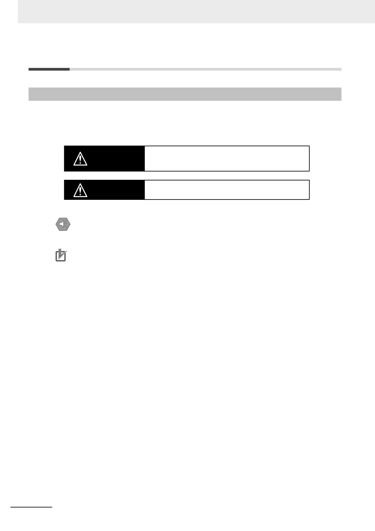
Definition of Precautionary Information
The following notation is used in this manual to provide precautions required to ensure safe usage of an
NY-series Controller. The safety precautions that are provided are extremely important to safety.
Always read and heed the information provided in all safety precautions.
The following notation is used.
Indicates a potentially hazardous situation which, if not avoided,
WARNING could result in death or serious injury. Additionally, there may be
severe property damage.
Indicates a potentially hazardous situation which, if not avoided,
Caution
may result in minor or moderate injury, or property damage.
Precautions for Safe Use
Indicates precautions on what to do and what not to do to ensure safe usage of the product.
Precautions for Correct Use
Indicates precautions on what to do and what not to do to ensure proper operation and performance.
16
Safety Precautions
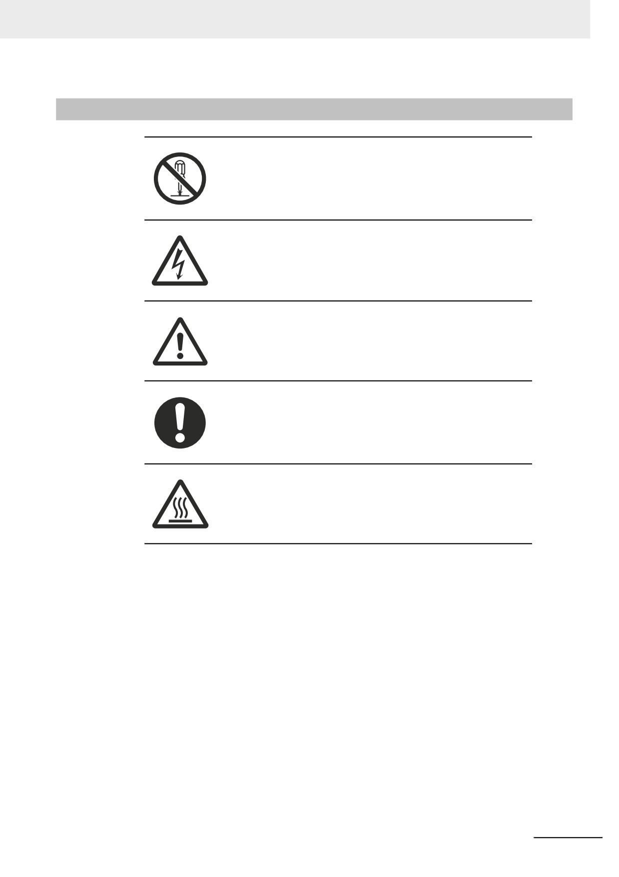
Symbols
The circle and slash symbol indicates operations that you must not do.
The specific operation is shown in the circle and explained in text.
This example indicates prohibiting disassembly.
The triangle symbol indicates precautions (including warnings).
The specific operation is shown in the triangle and explained in text.
This example indicates a precaution for electric shock.
The triangle symbol indicates precautions (including warnings).
The specific operation is shown in the triangle and explained in text.
This example indicates a general precaution.
The filled circle symbol indicates operations that you must do.
The specific operation is shown in the circle and explained in text.
This example shows a general precaution for something that you must do.
The triangle symbol indicates precautions (including warnings).
The specific operation is shown in the triangle and explained in text.
This example indicates a precaution for high temperatures.
17
Safety Precautions
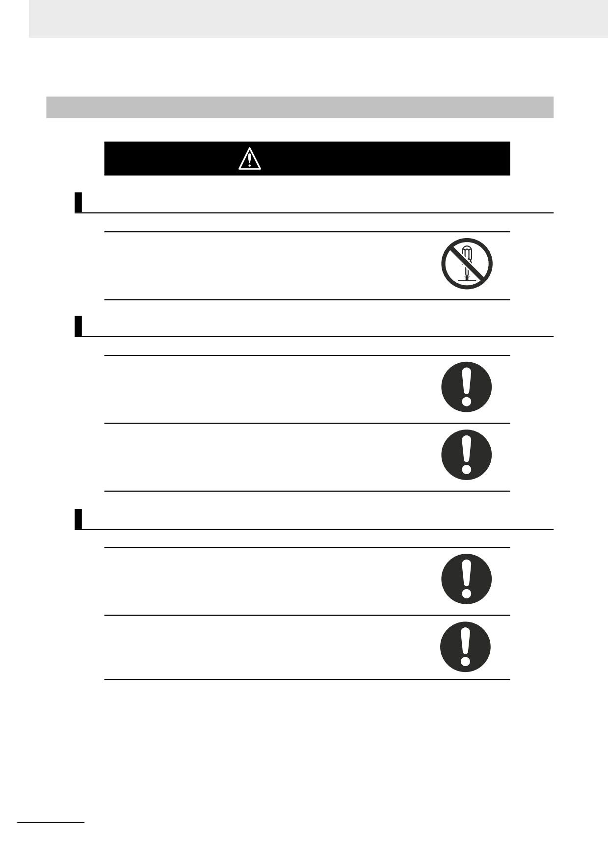
Warnings
WARNING
Disassembly and Dropping
Do not attempt to disassemble, repair, or modify the product in any way.
Doing so may result in malfunction or fire.
Installation
Always connect to a ground of 100 Ω or less when installing the products.
Ensure that installation and post-installation checks of the product are per-
formed by personnel in charge who possess a thorough understanding of the
machinery to be installed.
Fail-safe Measures
Provide safety measures in external circuits to ensure safety in the system if
an abnormality occurs due to malfunction of the product or due to other
external factors affecting operation. Not doing so may result in serious acci-
dents due to incorrect operation.
Emergency stop circuits, interlock circuit, limit circuits, and similar safety
measures must be provided in external control circuits.
18
Safety Precautions
The CPU Unit will turn OFF all outputs from Output Units in the following
cases. The slaves will operate according to the settings in the slaves.
• If an error occurs in the power supply
• If a CPU watchdog timer error or CPU reset occurs
• If a major fault level Controller error occurs
• While the product is on standby until RUN mode is entered after the power
is turned ON
• If a system initialization error occurs
External safety measures must be provided to ensure safe operation of the
system in such cases.
If external power supplies for slaves or other devices are overloaded or
short-circuited, the voltage will drop, outputs will turn OFF, and the system
may be unable to read inputs. Provide external safety measures in controls
with monitoring of external power supply voltage as required so that the sys-
tem operates safely in such a case.
Unintended behavior may occur when an error occurs in internal memory of
the product. As a countermeasure for such problems, external safety mea-
sures must be provided to ensure safe operation of the system.
Provide measures in the communications system and user program to
ensure safety in the overall system even if errors or malfunctions occur in
data link communications or remote I/O communications.
If there is interference in remote I/O communications or if a major fault level
error occurs, output status will depend on the products that are used.
Confirm the operation that will occur when there is interference in communi-
cations or a major fault level error, and implement safety measures. Adjust all
of the settings in the slaves and Units.
The use of an uninterruptible power supply (UPS) allows normal operation to
continue even if a momentary power failure occurs, possibly resulting in the
reception of an erroneous signal from an external device affected by the
momentary power failure. Take external fail-safe measures. Where neces-
sary, monitor the power supply voltage on the system for external devices
and use it as an interlock condition.
Do not use the input functions of the touchscreen in applications that involve
human life, in applications that may result in serious injury, or for emergency
stop switches.
19
Safety Precautions
Downloading
Always confirm safety at the destination before you transfer a user program,
configuration data, setup data, or device variables from the Sysmac studio.
The devices or machines may perform unexpected operation regardless of
the operating mode of the product.
Actual Operation
Check the user program, data, and parameter settings for proper execution
before you use them for actual operation.
Security setting adjustments should only be performed by the engineer in
charge that possesses a thorough understanding of the security settings.
Selecting non-recommended security settings can put your system at risk.
Changing BIOS information is only allowed for the engineer in charge who
possesses a thorough understanding of the BIOS settings because it can
change the behavior of the product.
Water or other liquid present on the touchscreen surface may create false
touch behavior and unexpected operation. Wipe away the liquid on the
touchscreen before operation.
20
Safety Precautions
Cautions
Caution
Installation
When installing or removing a PCIe card, ensure to grip the Card Clip on the
sides to prevent contact with the sharp edges of the sheet metal frame tab.
Injury may result.
Wiring
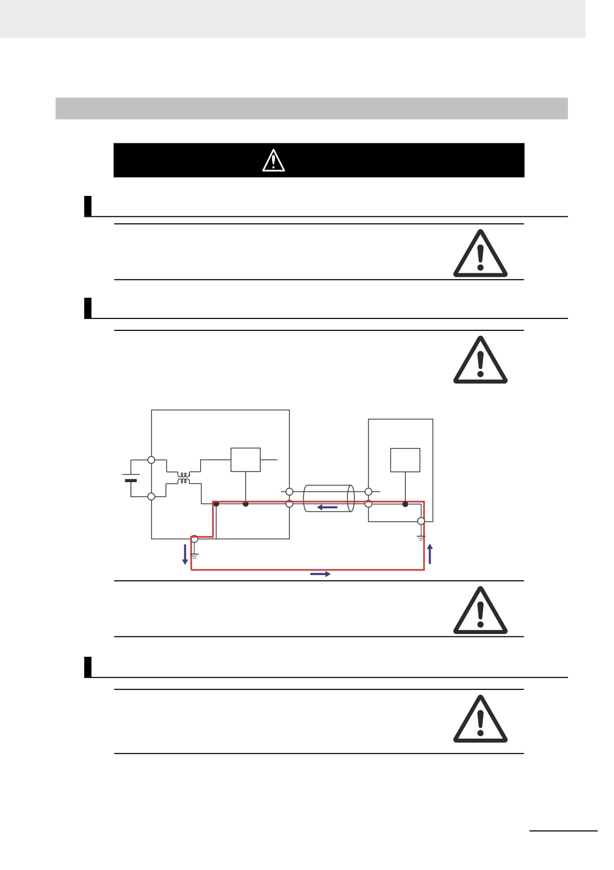
The product has an internal non-isolated DC power supply. Circuit ground
(0VDC) and frame ground are connected together. When connecting a non-
isolated device or a non-isolated interface to the product, take appropriate
actions to avoid communication failures or damage to the mentioned ports.
Non-isolated
Industrial PC Platform Product
Device
24 VDC
Non-isolated
Interface
0 VDC
Never ground the 24 VDC side of the power supply. This may cause a short
circuit.
Online Editing
Execute online editing only after confirming that no adverse effects will be
caused by deviations in the timing of I/O. If you perform online editing, the
task execution time may exceed the task period, I/O may not be refreshed
with external devices, input signals may not be read, and output timing may
change.
21
Precautions for Safe Use
Precautions for Safe Use
Disassembly, Dropping, Mounting, Installation and Storage
• Do not drop the product or subject it to abnormal vibration or shock. Doing so may result in product
malfunction or burning.
• When unpacking, check carefully for any external scratches or other damages. Also, shake the prod-
uct gently and check for any abnormal sound.
• Always use the devices specified in the relevant manual.
• Always install equipment that is included in the product specifications. Not doing so may result in fail-
ure or malfunction.
• Install the product in the correct orientation and temperature according to the specifications in the
manual to prevent overheating. Not doing so may result in malfunction.
• When connecting peripheral devices to the product, ensure sufficient countermeasures against noise
and static electricity during installation of the peripheral devices.
• The product must be installed in a control panel.
• The mounting panel must be between 1.6 and 6.0 mm thick. Tighten the Mounting Brackets evenly to
a torque of 0.6 Nm to maintain water and dust resistance. If the tightening torque exceeds the speci-
fied value, or the tightening is not even, deformation of the front panel may occur. Additionally, make
sure the panel is not dirty or warped and that it is strong enough to hold the product.
• Do not let metal particles enter the product when preparing the panel. Do not allow wire clippings,
shavings, or other foreign material to enter any product. Otherwise, the product burning, failure, or
malfunction may occur. Cover the product or take other suitable countermeasures, especially during
wiring work.
Wiring
•
Follow the instructions in the manual to correctly perform connector wiring and insertion. Double-
check all wiring and connector insertion before turning ON the power supply.
•
Always ensure connectors, cables, PCIe Cards and Storage devices are completely locked in place
to prevent accidental disconnection.
•
Before you connect a computer to the product, disconnect the power supply plug of the computer
from the AC outlet. Also, if the computer has an FG terminal, make the connections so that the FG
terminal has the same electrical potential on the product. A difference in electrical potential between
the computer and the product may cause failure or malfunction.
•
Do not bend or pull the cables beyond normal limit.
Do not place heavy objects on top of the cables or other wiring lines. Doing so may break the cables.
•
Always use power supply wires with sufficient wire diameters to prevent voltage drop and burning.
Make sure that the current capacity of the wire is sufficient. Otherwise, excessive heat may be gener-
ated. When cross-wiring terminals, the total current for all the terminals will flow in the wire. When
wiring cross-overs, make sure that the current capacity of each of the wires is not exceeded.
•
Be sure that all mounting bracket screws and cable connector screws are tightened to the torque
specified in the relevant manuals. The loose screws may result in fire or malfunction.
•
Use crimp terminals for wiring.
•
Use a power cable with a conductor cross-section of 0.2mm2 to 2.5mm2. Remove 7 mm of sheath
before connecting the wires.
•
Observe the following precautions to prevent broken wires.
• When you remove the sheath, be careful not to damage the conductor.
• Connect the conductor without twisting the wires.
•
Do not weld the conductors. Doing so may cause the wires to break with vibration.
22
Precautions for Safe Use
Task Design
• If the following variables are specified for a condition expression when the execution condition is a
condition expression for a variable, event tasks may not be executed when conditions are met or
event tasks may be executed when conditions are not met.
• Structure members whose data size is 16 bits or more, except for system-defined variables for
motion control
• Array elements whose data size is 16 bits or more
For information on event task execution conditions, refer to the NY-series Industrial Panel PC / Indus-
trial Box PC Software User's Manual (Cat. No. W558).
Power Supply Design and Turning ON/OFF the Power Supply
•
Always use a power supply that provides power within the rated range.
•
Use a DC power supply with a slight voltage fluctuation that will provide a stable output even if the
input is momentarily interrupted for 10 ms. Use a DC power supply with reinforced insulation or dou-
ble insulation. The rated power supply voltage is 24 VDC with an allowable range of 19.2 to 28.8
VDC.
•
Do not perform a dielectric strength test.
•
Always use the recommended uninterruptable power supply (UPS) to prevent data loss and other
system file integrity issues caused by unexpected power interruption. Back up the system files in the
planned way to prevent data loss and other system file integrity issues caused by incorrect operation.
•
Use an Omron S8BA UPS with the correct revision number to prevent improper system shutdown.
•
It takes up to approximately 10 to 20 s to enter RUN mode after the power is turned ON. The outputs
during this time behave according to the slave or Output Unit specifications. Implement fail-safe cir-
cuits so that external devices do not operate incorrectly.
•
Power ON after the DVI cable is connected between the product and an external monitor.
•
Always check the power supply and power connections before applying power. Incorrect power con-
nections can damage the product or cause burning.
•
Do not turn ON the power supply to the product when a part of a human body or a conductive object
is touching the surface of the touchscreen. Doing so will cause the touchscreen functionality to be
disabled. Remove the conductive object and cycle the power supply to restore the touchscreen func-
tionality.
•
Always turn OFF the power supply to system before you attempt any of the following.
• Inserting or removing PCIe cards
• Connecting cables
• Wiring the system
• Connecting or disconnecting the connectors
• Replacing or removing the HDD/SSD.
• Replace the Battery
• Replace the Fan Unit
Actual Operation
• Choose a OS password that is not obvious to prevent unauthorized access.
• Remember the OS user name and password. The product is inaccessible without it.
• Before operating the system, please make sure the appropriate software is installed and configured.
Doing so may prevent unexpected operation.
• Install all updates and ensure the browser stays up-to-date.
• Install all updates and ensure the firewall stays up-to-date.
• Make sure that your OS environment is protected against malicious software and viruses.
23
Precautions for Safe Use
• Install all updates and ensure virus definitions stay up-to-date.
• Do not remove the fan cover while the power is ON. Contact with the rotating fan may result in injury.
• Virtual memory settings can affect the performance of the system. Disable the paging file after instal-
lation of applications or updates.
• Correctly perform wiring and setting, and ensure that the shutdown by the UPS can be executed.
• Always create a Rescue Disk using the Rescue Disk Utility and restore to recover the HDD/SSD con-
figuration if necessary.
Operation
•
Confirm that no adverse effect will occur in the system before you attempt any of following.
• Changing the operating mode of the product (including changing the setting of the Startup Mode)
• Changing the user program or settings
• Changing set values or present values
• Forced refreshing
•
Do not carry out the following operations when accessing a USB device or an SD Memory Card.
• Turn OFF the power supply of the product.
• Press the Power Button of the product.
• Remove a USB device or SD memory card.
•
If two different function modules are used together, such as when you see PCIe connected board and
EtherCAT slaves, take suitable measures in the user program and external controls to ensure that
safety is maintained in the controlled system if one of the function modules stops. The relevant out-
puts will behave according to the slave or Output Unit specifications if a partial fault level error occurs
in one of the function modules.
•
Do not attempt to remove or touch the fan unit while the product is powered ON or immediately after
the power supply is turned OFF. If you attempt to replace the fan unit then, there is a risk of personal
injury due to hot or rotating parts.
•
Press the power button for several seconds to force the product shutdown. Always back up files in
the planned way to prevent data loss or system file corruption.
•
Do not touch any product housing when power is being supplied or immediately after the power sup-
ply is turned OFF. Doing so may result in burn injury.
•
Confirm the safety of the system before using the touch panel.
•
Signals from the touchscreen may not be entered if the touchscreen is pressed consecutively at high
speed. Only move on to the next operation after confirming that the product has detected the previ-
ous input of the touchscreen.
•
Do not accidentally press the touchscreen when the backlight is not lit or when the display does not
appear. Confirm the safety of the system before pressing the touchscreen.
•
Do not use hard or pointed objects to operate or scrub the touchscreen, otherwise the surface of the
touchscreen may be damaged.
•
Always confirm safety at the connected equipment before you perform the following operations when
the device output hold configuration is set to enable. The equipment may operate unexpectedly
because the last status for outputs is retained.
• Changing the operating mode of the product
• When downloaded
General Communications
• Unexpected operation may result if inappropriate data link tables are set. Even if appropriate data link
tables have been set, confirm that the the controlled system will not be adversely affected before you
transfer the data link tables. The data links start automatically after the data link tables are trans-
ferred.
• Separate the machine network segment from the office network to avoid communication failures.
24

Precautions for Safe Use
EtherNet/IP Communications
• Make sure that the communications distance, number of nodes connected, and method of connec-
tion for EtherNet/IP are within specifications. Do not connect EtherNet/IP communications to Ether-
CAT or other networks. An overload may cause the network to fail or malfunction.
• All related EtherNet/IP nodes are reset when you transfer settings for the built-in EtherNet/IP port
(including IP addresses and tag data links settings). The settings can only be enabled after the reset.
Confirm that the system will not be adversely affected by resetting nodes before you transfer the set-
tings.
• If EtherNet/IP tag data links (cyclic communications) are used with a repeating hub, the communica-
tions load on the network will increase. This will increase collisions and may prevent stable communi-
cations. Do not use repeating hubs on networks where tag data links are used. Use an Ethernet
switch instead.
EtherCAT Communications
•
Malfunctions or unexpected operation may occur for some combinations of EtherCAT revisions of the
master and slaves. If you disable the revision check in the network settings, use the Sysmac Studio
to check the slave revision settings in the master and the actual slave revisions, and then make sure
that functionality is compatible in the slave manuals or other references. You can check the actual
slave revisions from the Sysmac Studio or on slave nameplates.
•
If the Fail-soft Operation Setting is set to stop operation, process data communications will stop for all
slaves when an EtherCAT communications error is detected in a slave. At that time, the Servo Drive
will operate according to the Servo Drive specifications. Make sure that the Fail-soft Operation Set-
ting results in safe operation when a device error occurs.
•
If noise occurs or an EtherCAT slave is disconnected from the network, any current communications
frames may be lost. If frames are lost, slave I/O data is not communicated, and unintended operation
may occur. The slave outputs will behave according to the slave specifications. Refer to the manual
for the slave. If a noise countermeasure or slave replacement is required, perform the following pro-
cessing.
• Program the Input Data Invalid system-defined variable as an interlock condition in the user pro-
gram.
• Set the PDO communications timeout detection count setting in the EtherCAT master to at least 2.
Refer to the NY-series Industrial Panel PC / Industrial Box PC Built-in EtherCAT Port User’s Man-
ual (Cat. No. W562) for details.
•
EtherCAT communications are not always established immediately after the power supply is turned
ON. Use the system-defined variables in the user program to confirm that communications are estab-
lished before attempting control operations.
•
When an EtherCAT slave is disconnected or disabled, communications will stop and control of the
outputs will be lost not only for the disconnected slave, but for all slaves connected after it. Confirm
that the system will not be adversely affected before you disconnect or disable a slave.
•
You cannot use standard Ethernet hubs or repeater hubs with EtherCAT communications. If you use
one of these, a major fault level error or other error may occur.
•
Always use the specified EtherCAT slave cables. If you use any other cable, the EtherCAT master or
the EtherCAT slaves may detect an error and one of the following may occur.
• Continuous refreshing of process data communications will not be possible.
• Continuous refreshing of process data communications will not end during the set cycle.
Motion Control
• The motor is stopped if communications are interrupted between the Sysmac Studio and the product
during an MC Test Run. Connect the communications cable between the computer and product
securely and confirm that the system will not be adversely affected before you perform an MC Test
Run.
25
Precautions for Safe Use
• The positive drive prohibit input (POT), negative drive prohibit input (NOT), and home proximity input
(DEC) of the Servo Drive are used by the MC Function Module as the positive limit input, negative
limit input, and home proximity input. Make sure that the signal widths for all of these input signals
are longer than the control period of the MC Function Module. If the input signal widths are shorter
than the control period, the MC Function Module may not be able to detect the input signals, resulting
in incorrect operation.
• Always execute the Save Cam Table instruction if you change any of the cam data from the user pro-
gram in the CPU Unit or from the Sysmac Studio. If the cam data is not saved, the previous condition
will be restored when the power is turned ON again, possibly causing unexpected machine opera-
tion.
• Confirm the axis number carefully before you perform an MC Test Run.
• Use the NX_AryDOutTimeStamp (Write Digital Output Array with Specified Time Stamp) instruction
only after you confirm that InOperation from the MC_DigitalCamSwitch (Enable Digital Cam Switch)
instruction is TRUE.
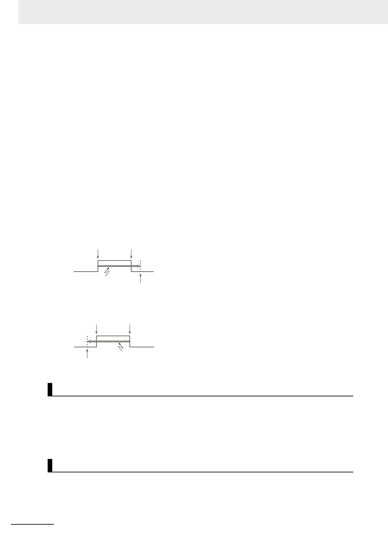
• Always use the axis at a constant velocity for the MC_DigitalCamSwitch (Enable Digital Cam Switch)
instruction.
If you set the Count Mode to Rotary Mode, the following operation will occur if you use OnCompensa-
tion or OffCompensation and the axis velocity changes abruptly.
• If the value of OnCompensation or OffCompensation is equivalent to the time for half a rotation or
more, InOperation will be FALSE.
• If the value of OnCompensation results in exceeding LastOnPosition, the output timing will be
unstable.
FirstOnPosition LastOnPosition
OnCompensation
FirstOnPosition after compensation
• If the value of OffCompensation results in exceeding FirstOnPosition, the output timing will be
unstable.
FirstOnPosition LastOnPosition
OffCompensation
LastOnPosition after compensation
Backup
• We recommend that you back up the present values of variables while the retained variables are not
refreshed.
If you back up while the values of retained variables are refreshed, the data may not be saved cor-
rectly.
For information on Backup Functions and a backup for present values of variables, refer to the NY-
series Industrial Panel PC / Industrial Box PC Software User's Manual (Cat. No. W558).
Restoring Data
• The absolute encoder home offsets are backed up with a non-volatile memory in the product as
absolute encoder information. If any of the following conditions is met, clear the absolute encoder
home offsets from the list of data items to restore, and then restore the data. Then, define the abso-
lute encoder home again. If you do not define home, unintended operation of the controlled system
may occur.
26
Precautions for Safe Use
• The Servomotor or Servo Drive was changed since the data was backed up.
• The absolute encoder was set up after the data was backed up.
• The absolute data for the absolute encoder was lost.
• You can partially or cannot at all back up, restore, or compare data of the settings depending on
slaves and Units. Also, you cannot back up, restore, or compare data for disabled slaves or Units.
After you restore data, sufficiently confirm that operation is correct before you start actual operation.
Battery Replacement
• Dispose of any Battery that has been dropped on the floor or otherwise subjected to excessive
shock. Batteries that have been subjected to shock may leak if they are used.
• UL standards require that only an experienced engineer replace the Battery. Make sure that an expe-
rienced engineer is in charge of Battery replacement.
• The Battery may leak, rupture, heat, or ignite. Never short-circuit, charge, disassemble, heat, or
incinerate the Battery or subject it to strong shock.
Fan Unit Replacement
• In the case of an extended storage period, check the performance of the fan unit before production
starts.
Product Replacement
• Make sure that the required data, including the user program, configurations, settings and variables
is transferred to a product that was replaced and to externally connected devices before restarting
operation.
Be sure to include the tag data link settings and routing tables, which are stored in the product.
Cleaning, Maintenance and Disposal
• Do not use corrosive substances to clean the product. Doing so may result in the failure or malfunc-
tion.
• Periodically check the installation conditions in applications where the product is subject to contact
with oil or water.
• As the rubber gasket will deteriorate, shrink, or harden depending on the operating environment,
periodical inspection is necessary.
• Dispose of the product and Batteries according to local ordinances as they apply.
• The following information must be displayed for all products that contain primary lithium batteries with
a perchlorate content of 6 ppb or higher when shipped to or transported through the State of Califor-
nia, USA.
Perchlorate Material - special handling may apply.
• The product contains a lithium battery with a perchlorate content of 6ppb or higher. When exporting
an end product containing the product to or shipping through California, USA, label all packing and
shipping containers appropriately.
27
Precautions for Correct Use
Precautions for Correct Use
Storage, Installation and Mounting
•
Do not operate or store the product in the following locations. Operation may stop or malfunctions
may occur.
• Locations subject to direct sunlight
• Locations subject to temperatures or humidity outside the range specified in the specifications
• Locations subject to condensation as the result of severe changes in temperature
• Locations subject to corrosive or flammable gases
• Locations subject to dust (especially iron dust) or salts
• Locations subject to exposure to water, oil, or chemicals
• Locations subject to shock or vibration
• Locations outdoors subject to direct wind and rain
• Locations subject to strong ultraviolet light
•
Always install the product with sufficient surrounding space to allow for adequate heat dissipation and
cooling effect.
•
Take appropriate and sufficient countermeasures when installing the product in the following loca-
tions.
• Locations subject to strong, high-frequency noise
• Locations subject to static electricity or other forms of noise
• Locations subject to strong electromagnetic fields
• Locations subject to possible exposure to radioactivity
• Locations close to power lines
•
Always touch a grounded piece of metal to discharge static electricity from your body before starting
an installation or maintenance procedure.
•
Insert USB devices and PCIe devices correctly to avoid the burning, failure or malfunction.
•
Execute a backup of the product before PCIe addition or replacement. Be sure that the PCIe device
works correctly before you use them for actual operation. PCIe devices and their related software
may cause an OS boot failure or crash.
•
The backlight has a finite life and if that is exceeded, the product may fail or malfunction. Check the
brightness periodically and if necessary, replace the product.
Wiring
• Always ensure the rated supply voltage is connected to the product.
• Do not allow wire clippings, shavings, or other foreign material to enter the product. Otherwise, burn-
ing, failure, or malfunction may occur. Cover the products or take other suitable countermeasures,
especially during wiring work.
• Ensure that available software checks are performed by personnel in charge who possess a thor-
ough understanding of the software.
• Do not use cables exceeding the maximum specified length. Doing so may cause malfunction.
• Do not connect an AC power supply to the DC power connector.
Power Supply Design and Turning OFF the Power Supply
• If the product experiences a sudden loss of power or disconnecting the cable while saving a setting
or transfer of data is underway, the changes may not be stored and unexpected behavior may occur.
28

Precautions for Correct Use
Actual Operation and Operation
•
After an OS update or a peripheral device driver update for the product is executed, the product
behavior might be different. Confirm that operation is correct before you start actual operation.
•
Ensure the fan is operational to provide adequate cooling while the power is turned ON.
•
HDD and SSD storage devices, SD Memory Cards, Power button, Fan unit and Battery have finite
lives and if those are exceeded, the product may fail or malfunction.
•
Always monitor the fan status. If a fan is used beyond its service life, the Low Revolution Speed
warning message is displayed and the product overheating may occur.
•
Monitor the battery's condition. When a battery has low voltage, the system time will be lost.
•
You can operate the touchscreen even when you wear some gloves. Confirm that you can correctly
operate the touchscreen while wearing gloves prior to actual operation.
•
Do not reset or power OFF the product while the password is being changed. If you fail to save the
password there is a possibility that the project will not work.
•
Always confirm safety at the connected equipment before you reset Controller errors with an event
level of partial fault or higher from the EtherCAT master Function Module. When the Error is reset, all
slaves that were in any state other than Operational state due to a Controller error with an event level
of partial fault or higher (in which output are disabled) will go to Operational state and the outputs will
be enabled. Before you reset all errors or restart a slave, confirm that no Controller errors with an
event level of partial fault have occurred for the EtherCAT Master Function Module.
•
The functions that are supported depend on the unit version of the product. The version of Sysmac
Studio that supports the functions that were added for an upgrade is also required to use those func-
tions. Refer to Version Information for NY-series Controllers for the relationship between the unit ver-
sions of the controller and the Sysmac Studio versions, and for the functions that are supported by
each unit version.
•
The touchscreen supports 5 simultaneous touches. When the number of touches is exceeded, not all
touch points will be detected.
•
The capacitive touchscreen reacts to contact on its surface. Accidental touching the surface of the
touchscreen may cause unintended behavior.
•
Confirm the device output hold configuration before you change the operating mode of the product or
execute the download.
Error Processing
• In applications that use the results of instructions that read the error status, consider the effect on the
system when errors are detected and program error processing accordingly. For example, even the
detection of a minor error, such as Battery replacement during operation, can affect the system
depending on how the user program is written.
• If you change the event level of a Controller error, the output status when the error occurs may also
change. Confirm safety before you change an event level.
Debugging
• If you use data tracing to sample following variables, correct data may not be sampled.
• Structure members whose data size is 16 bits or more, except for system-defined variables for
motion control
• Array elements whose data size is 16 bits or more
For information on data tracing, refer to the NY-series Industrial Panel PC / Industrial Box PC Soft-
ware User's Manual (Cat. No. W558).
29

Precautions for Correct Use
Restoring
• When you edit the restore command file, do not change anything in the file except for the “yes” and
“no” specifications for the selectable data groups. If you change anything else in the file, the Control-
ler may perform unexpected operation when you restore the data.
Task Settings
• If a Task Period Exceeded error occurs, shorten the programs to fit in the task period or increase the
setting of the task period.
Motion Control
• Before you start an MC Test Run, make sure that the operation parameters are set correctly.
• Do not download motion control settings during an MC Test Run.
EtherCAT Communications
• Set the Servo Drives to stop operation if an error occurs in EtherCAT communications between the
Controller and a Servo Drive.
• If you need to disconnect the cable from an EtherCAT slave during operation, first disconnect the
software connection to the EtherCAT slave or disable the EtherCAT slave and all of the EtherCAT
slaves that are connected after it.
• Make sure that all of the slaves to be restored are participating in the network before you reset a Net-
work Configuration Verification Error, Process Data Communications Error, or Link OFF Error in the
EtherCAT Master Function Module. If any slave is not participating when any of these errors is reset,
the EtherCAT Master Function Module may access slave with a different node address than the
specified node address or the error may not be reset correctly.
• Make sure that the communications distance, number of devices connected, and method of connec-
tion for EtherCAT are within specifications. Do not connect EtherCAT communications to EtherNet/IP,
a standard in-house LAN, or other networks. An overload may cause the network to fail or malfunc-
tion.
• After you transfer the user program, the product is restarted and communications with the EtherCAT
slaves are cut off. During that period, the slave outputs behave according to the slave specifications.
The time that communications are cut off depends on the EtherCAT network configuration. Before
you transfer the user program, confirm that the system will not be adversely affected.
Battery Replacement
• Turn ON the power after replacing the Battery for a product that has been unused for a long time.
Leaving the product unused again without turning ON the power even once after the Battery is
replaced may result in a shorter Battery life.
• Make sure to use a battery of the correct type, install the battery properly.
• Apply power for at least five minutes before changing the battery. Mount a new battery within five
minutes after turning OFF the power supply. If power is not supplied for at least five minutes, the
clock data may be lost. Check the clock data after changing the battery.
SD Memory Cards
• Insert an SD memory card completely and ensure it is in place.
30
///////////////////////////////////////