Omron IPC Machine Controller Industrial Panel PC / Industrial Box PC. Software User’s Manual (Industrial PC Platform NY-series) - page 3
2 NY-series Controller Operation
Processing Executed with Tasks
z
Types of Processing That are Executed with Tasks
The following processing is performed with tasks.
Processing
Description
I/O refreshing
Data I/O for EtherCAT slaves is performed.
User program execution
The user programming for sequence control is executed. It also sends com-
mands to the motion control process.
Motion control
Motion control is executed based on commands from the user program.
System common process-
System common processing, such as data trace processing and tag data link
ing
processing, is performed.
Refer to 5-3-3 Basic Operation of Tasks for NY-series Controllers for details on the processing that is
executed with tasks.
z
Task Operation
Processing is assigned to tasks. There are three kinds of tasks, as shown in the following table.
They are defined by their execution priorities and execution conditions.
Execution priority
Type of peri-
Main processing con-
(smaller values indicate higher pri-
Execution condition
odic task
tent
ority)
Primary periodic
4
The primary periodic
I/O refreshing, user
task
task is periodically exe-
program execution,
This task has the highest execution
cuted.
and motion control
priority.
Periodic tasks
16, 17, or 18
The primary periodic
The processing that
task is periodically exe-
can be performed
cuted.
depends on the task
execution priority.
The task period is an
integer multiple of the
Execution priority 16,
task period of the pri-
17, or 18: User pro-
mary periodic task.
gram execution
Event tasks
8 or 48
An event task is exe-
User program execu-
cuted only once when
tion
the specified condition
is met.
2-6
2 NY-series Controller Operation
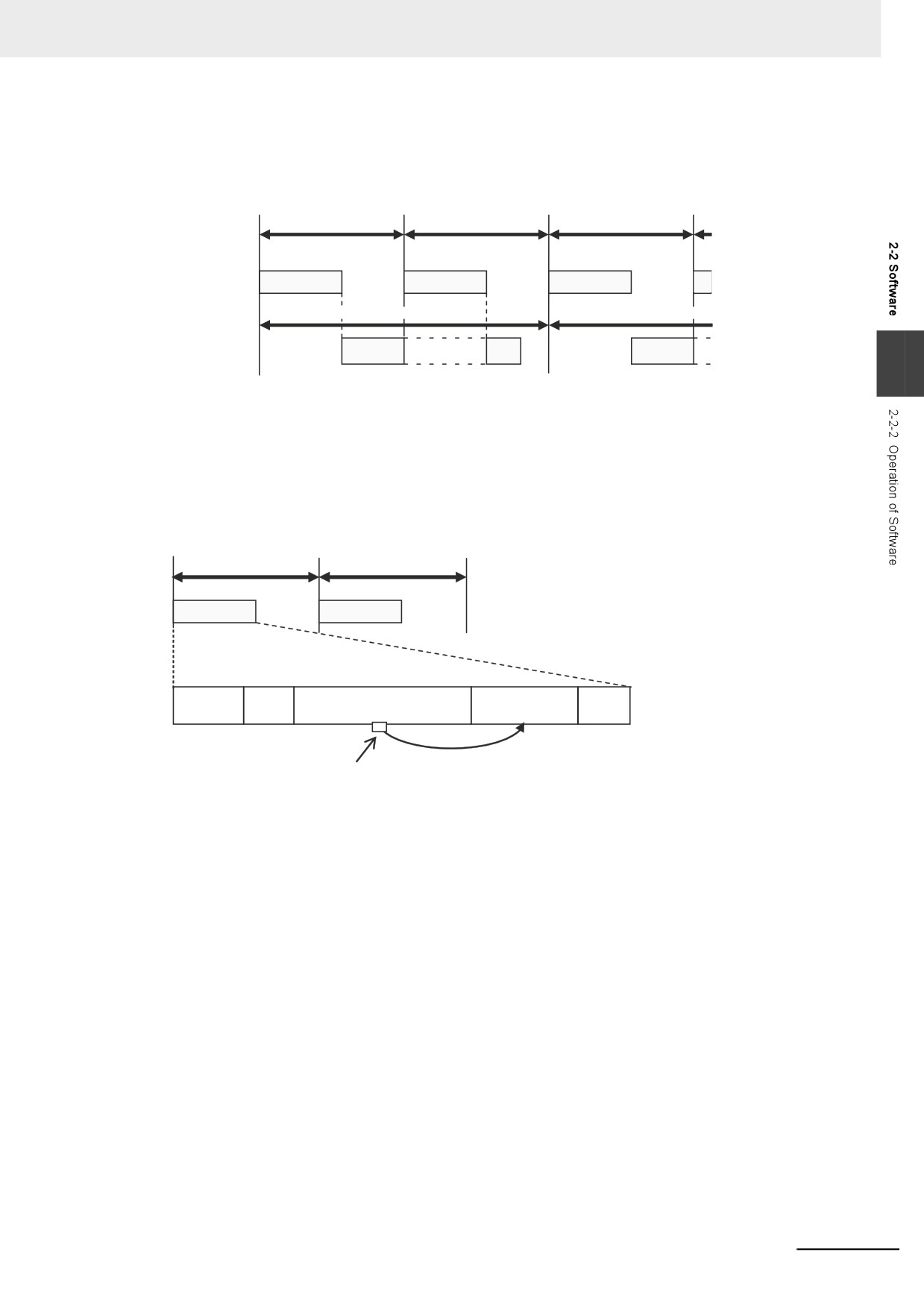
The Controller executes the task with the highest execution priority first. The following operation
example is for the primary periodic task and a periodic task. If the primary periodic task is ready for
execution while a periodic task is in execution, execution of the primary periodic task is prioritized.
Task period of primary
Task period of primary
Task period of primary
periodic task
periodic task
periodic task
Primary
Task
Task
Task
periodic task
Task period of periodic task
Task period of periodic task
Periodic task
Task
Task
Task
2
Refer to 5-2 Overview of Tasks for details on task operation.
z
Operation of Processing with Tasks
Processing that is assigned to a task is executed within the task in the order shown in the following
diagram. If the program contains a motion control instruction, the execution process for the program
in the task will send a command to the motion control process. The motion control process is exe-
cuted based on commands.
Task period
Task period
Task
Task
Processing
I/O
System
System
common
User program execution
Motion control
common
refreshing
processing
processing
Command
Motion control instruction
Note The Controller executes motion control in the primary periodic task. If the program that contains a motion
control instruction is assigned to the periodic task, the execution process for the program in the periodic task
will send a command to the motion control in the primary periodic task.
Refer to 5-9-3 System Input and Output Response Times for details.
2-7
2 NY-series Controller Operation
Tag Data Link Service
z
Processing Performed by the Tag Data Link Service
The tag data link service processes communications that use tags with other controllers or devices
on an EtherNet/IP network. You can use the built-in EtherNet/IP port in the Controller to connect to
an HMI.
z
Operation of the Tag Data Link Service
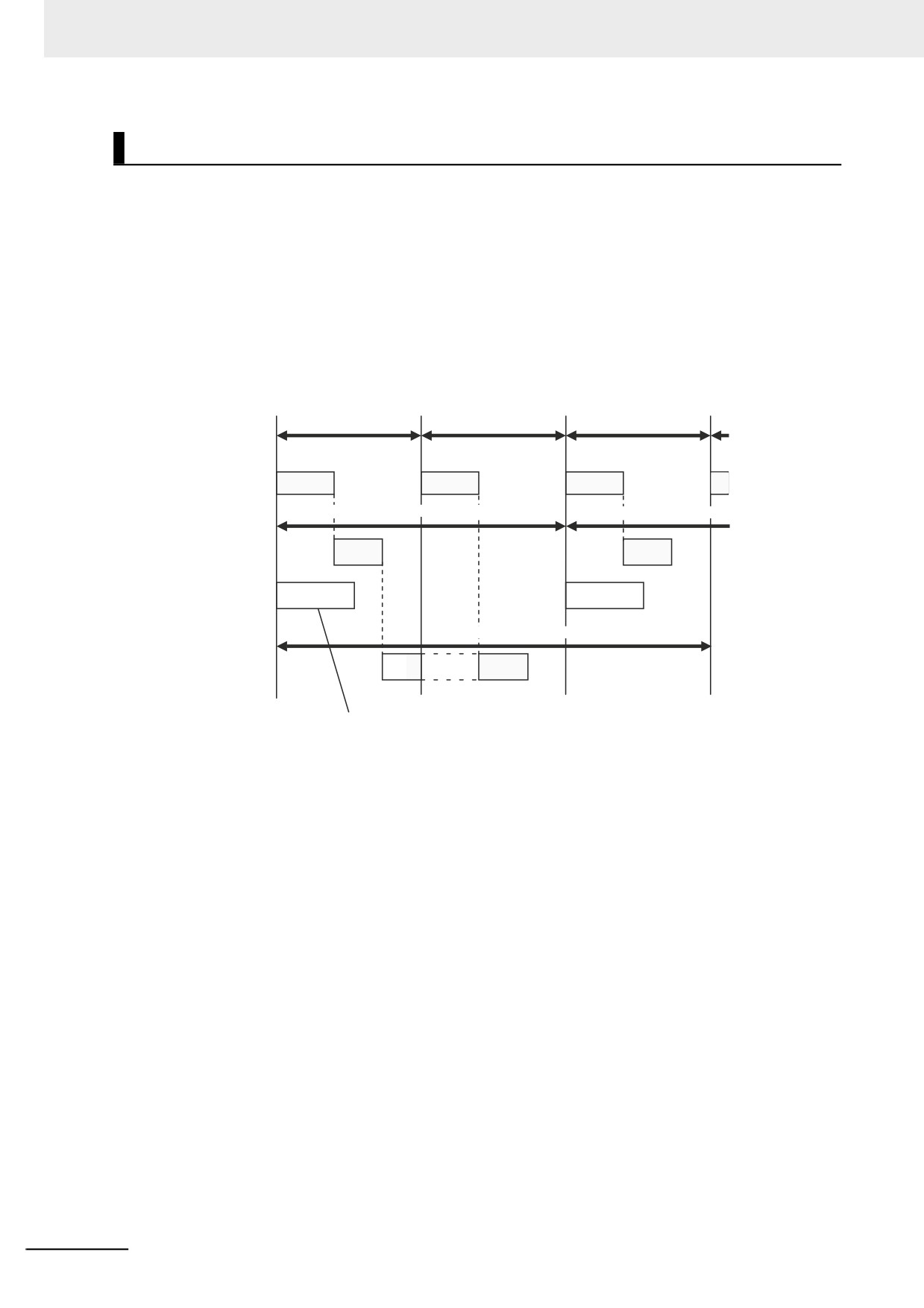
The tag data link service is executed periodically. The period and the time that is required for each
execution depend on the model of the Controller and on the tag data link settings.
The tag data link service is executed with the execution of tasks in parallel.
Task period of
Task period of
Task period of
primary periodic task
primary periodic task
primary periodic task
Primary
Task
Task
Task
periodic task
Task period of periodic task
Task period of periodic task
Priority-16 periodic
Task
Task
task
Tag data link
service
Task period of periodic task
Priority-17 periodic
task
Task
It is executed with the execution of tasks in parallel.
For details on the tag data link service, refer to 5-4 Tag Data Link Service and System Services.
2-8
2 NY-series Controller Operation
System Services
z
System Services
System services include the following processing.
Processing
Contents
Built-in EtherNet/IP port service
• Processing of message service requests, such as CIP commands, from
the Sysmac Studio, an HMI, host computers, or other Controllers
• Execution of communications instructions for CIP and socket communi-
cations
Built-in EtherCAT port service
• Execution of EtherCAT message communications
2
Virtual SD Memory Card ser-
• Access from FTP client
vice
• SD Memory Card operations from the Sysmac Studio
• Execution of SD Memory Card instructions
Self-diagnosis
• Hardware error detection
• Monitoring of Windows status
z
System Service Operations
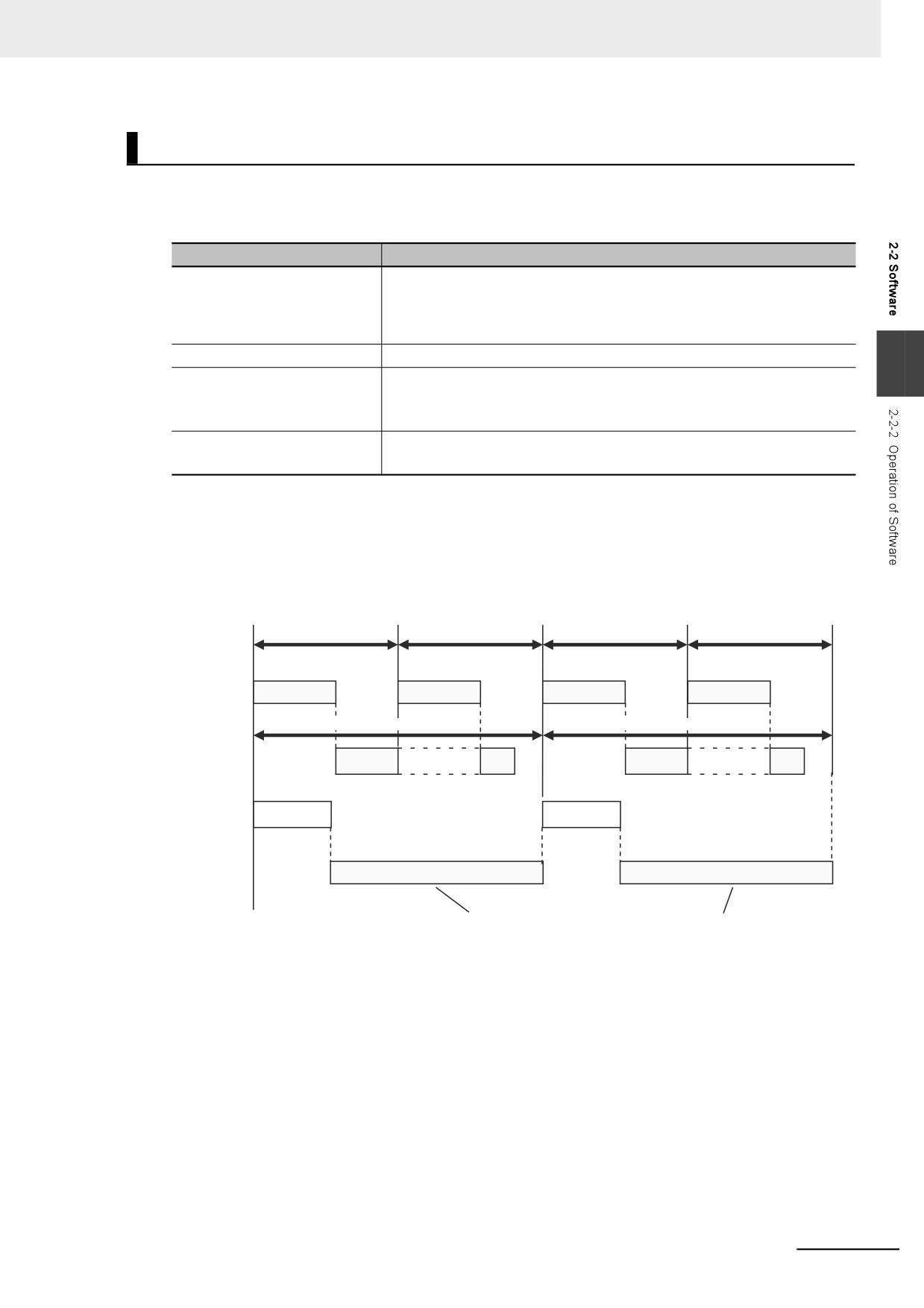
For NY-series Controller, if a request comes from the hardware or from outside of the Controller,
system services are executed in parallel with other processes. System services are executed at the
required time without being affected by the execution of tasks. However, the system services are not
executed while the tag data link service is in progress.
Task period of primary
Task period of primary
Task period of primary
Task period of primary
periodic task
periodic task
periodic task
periodic task
Primary
Task
Task
Task
Task
periodic task
Task period of periodic task
Task period of periodic task
Periodic task
Task
Task
Task
Task
Tag data link
service
System
services
The system services are executed in the unused time of the tag data link service.
Refer to 5-4 Tag Data Link Service and System Services for details on the system services.
2-9
2 NY-series Controller Operation
2-3
Accessing I/O
The NY-series Controller uses variables to access I/O. This section describes how variables are used
to access I/O.
In this manual, I/O on EtherCAT slaves are treated as I/O. Refer to the NY-series Industrial Panel PC /
Industrial Box PC Built-in EtherNet/IP Port User's Manual (Cat. No. W563) for details on how to access
data in other Controllers with tag data links.
2-3-1
Types of Variables
In an NY-series Controller, you use variables in the user program to access I/O and memory in the Con-
troller.
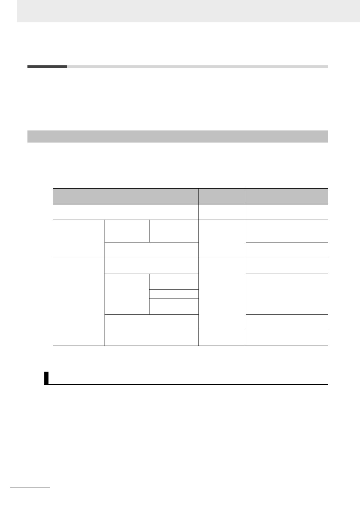
The type of a variable depends on whether it has attributes that are set by the user, and what it can
access.
Attribute set-
Variables
Accessed data
tings
User-defined variables
All attributes can
Controller
be set.
Semi-user-defined
Device variables
Device variables
Some attributes
EtherCAT slaves*2
variables
for EtherCAT
can be set.*1
slaves
Cam data variables
Servo Drives, encoder input
slaves, and Controller
System-defined
System-defined variables for PLC
No attributes can
Controller
variables
Function Module
be set.
System-defined
MC Common
Servo Drives, encoder input
variables for
Variable
slaves, and Controller
motion control
Axis Variables
Axes Group Vari-
ables
System-defined variables for Ether-
Built-in EtherNet/IP port
Net/IP
System-defined variables for Ether-
Built-in EtherCAT master port
CAT master
*1
Refer to Device Variable Attributes on page 3-7 for the attributes that can be set.
*2
“EtherCAT slaves” includes any NX Units on EtherCAT Slave Terminals.
User-defined Variables
The user defines all of the attributes of a user-defined variable. Refer to 6-3 Variables for details on
user-defined variables.
2-10
2 NY-series Controller Operation
Semi-user-defined Variables
Semi-user-defined variables have some attributes that you can set. These variables are used to access
specific data. A semi-user-defined variable can either be a device variable or a cam data variable,
depending on what it can access.
z
Device Variables
Device variables are used to access data in devices. A device is a general term for any Unit or slave
that is refreshed by the I/O refreshing that is performed by the Controller. Specifically, it refers to Eth-
erCAT slaves.
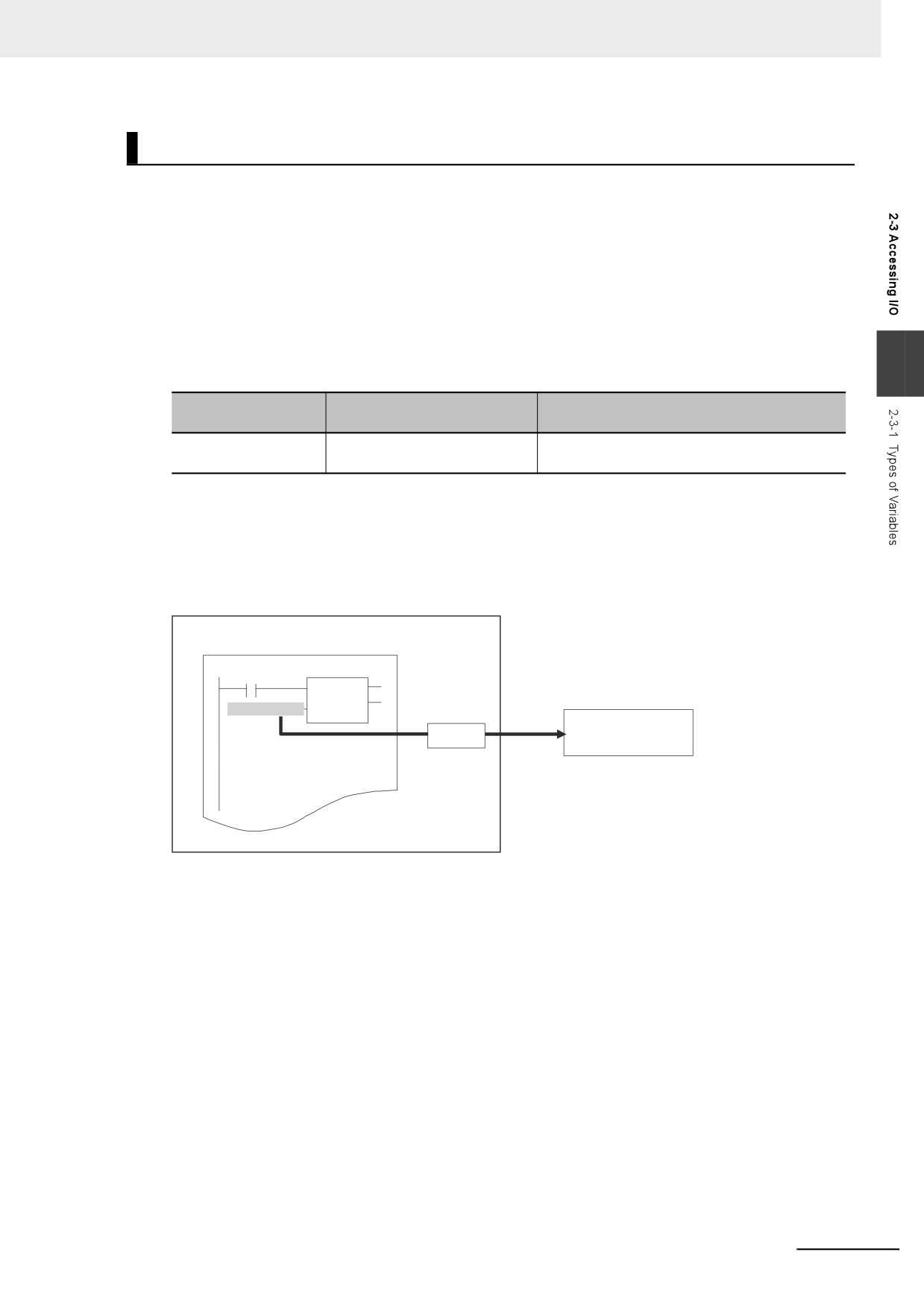
The device and the data to access in that device determine the type of device variable, as shown
below.
2
Type of device vari-
Device
Accessed data
able
Device variables for
EtherCAT slaves
Process data for EtherCAT slaves*1
EtherCAT slaves
*1 This refers to I/O data that is exchanged during the process data communications cycle between the mas-
ter and slaves.
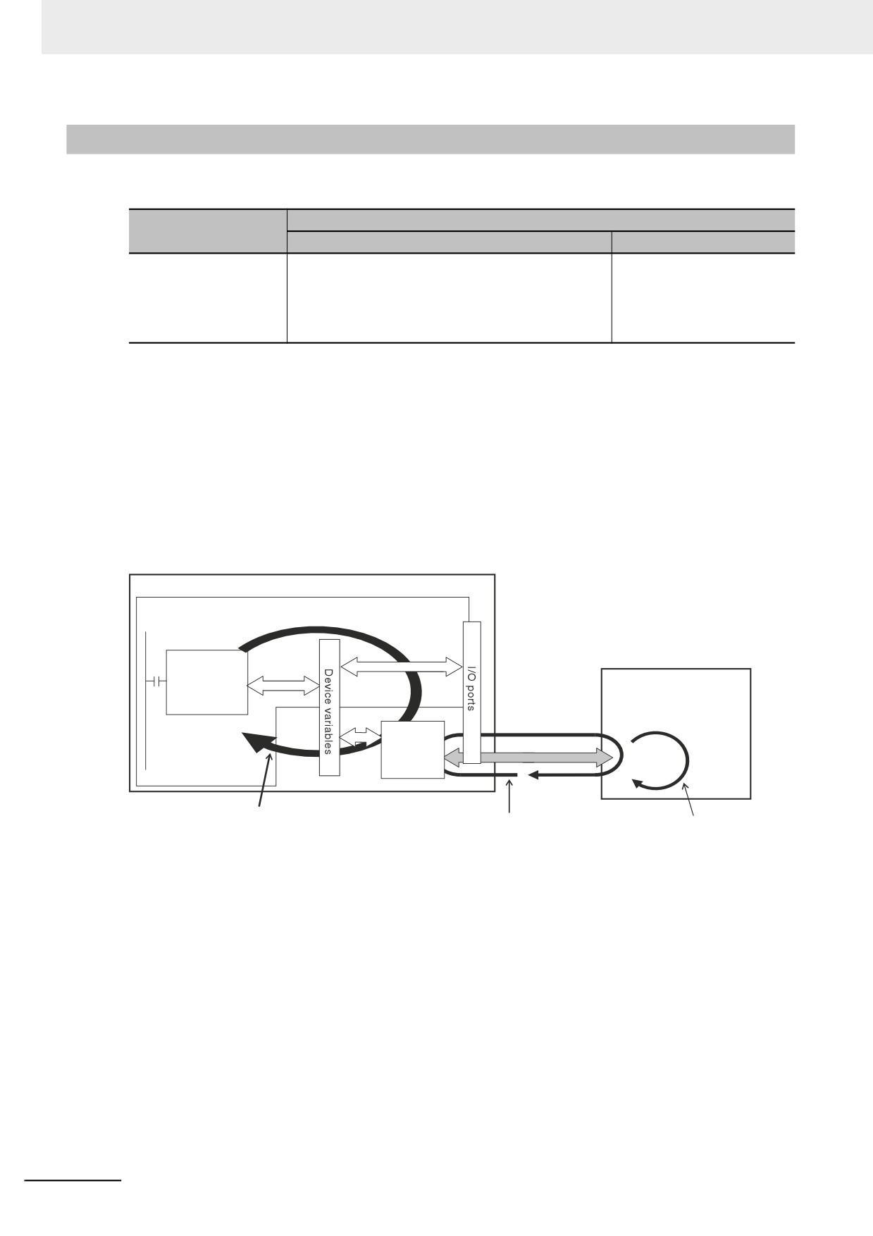
Device variables are used to access data for EtherCAT slaves through the I/O ports. The I/O ports
are logical ports that are used to access devices.
NY-series Controller
User program
Instruction
Device variable
I/O port
EtherCAT slave
Refer to 3-3-1 I/O Ports for details on I/O ports and device variables.
z Cam Data Variables
Cam data variables are used to access data in cam tables, which are used for motion control.
For details, refer to the NY-series Industrial Panel PC / Industrial Box PC Motion Control User's
Manual (Cat. No. W559).
2-11
2 NY-series Controller Operation
System-defined Variables
System-defined variables are defined in advance in an NY-series Controller. The names and all attri-
butes are defined by the system. They have specific functions. You cannot change the variable names
or any other attributes.
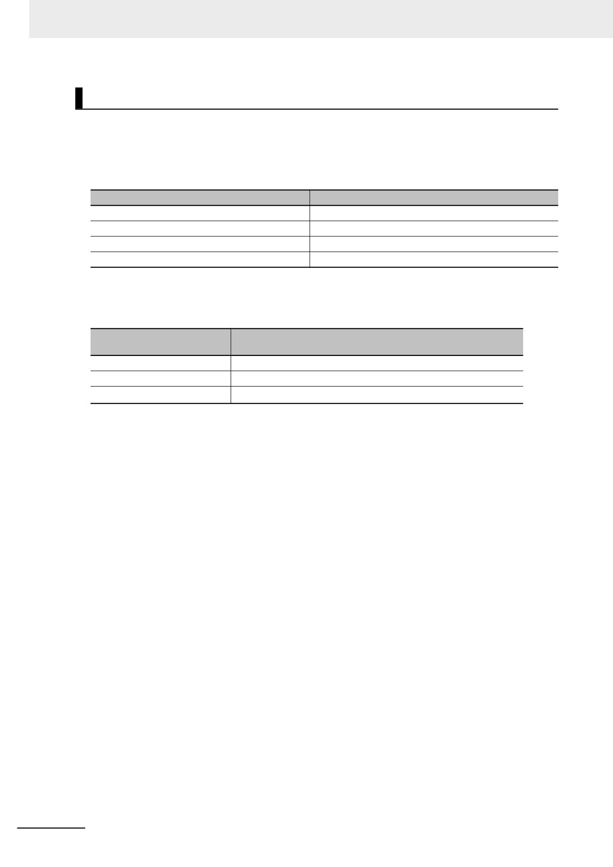
The system-defined variables are specific to a function module. There are system-defined variables for
each function module. The types of system-defined variables are listed in the following table.
Function module
Type of system-defined variable
PLC Function Module
System-defined variables for PLC Function Module
Motion Control Function Module
System-defined variables for motion control
EtherNet/IP Function Module
System-defined variables for EtherNet/IP
EtherCAT Master Function Module
System-defined variables for EtherCAT master
The system-defined variables for motion control are classified according to what the Motion Control
Function Module does, as listed in the following table.
System-defined variables for
Description
motion control
MC Common Variable
Common processing for the entire Motion Control Function Module
Axis variables
Control of individual axes
Axes Group variables
Control of axes groups*1
*1
An axes group consists of multiple axes. An axes group is used for interpolation.
Refer to A-3 System-defined Variables for details on system-defined variables.
2-12
2 NY-series Controller Operation
2-3-2
Accessing I/O with Variables
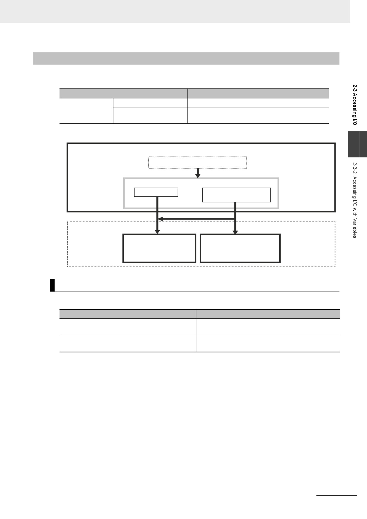
In the NY-series Controller, variables are used in the user program. Variables access the data of the
assigned I/O. The following table shows how I/O and variables are assigned in the NY-series Controller.
I/O
Variables
EtherCAT slaves
EtherCAT slaves
Device variables for EtherCAT slaves
EtherCAT slaves to which
Axis variables or device variables for EtherCAT slaves
axes are assigned
2
NY-series Controller
User program
Variables
Axis variables
Device variables for
EtherCAT slaves
*1
I/O
Servo Drive and
Servo Drive, encoder input,
encoder input slaves
and general-purpose slaves
that are assigned to axes
that are not assigned to axes
Accessing EtherCAT Slaves
The method that is used to access an EtherCAT slave depends on the type of EtherCAT slave.
Type of EtherCAT slave
Access method
• Servo Drive and encoder input slaves
These slaves are accessed through I/O ports by using
• General-purpose slaves
device variables for EtherCAT slaves.
Servo Drive and encoder input slaves that are
These slaves are accessed directly with Axis variables.*1
assigned to axes
*1
For a Servo Drive, one Servomotor is assigned as one axis to one Axis variable. For an encoder input slave,
one counter is assigned as one axis to one Axis variable.
Note EtherCAT slaves that cannot be assigned to axes are called general-purpose slaves. EtherCAT slaves that
can be assigned to axes are called Servo Drive and encoder input slaves. Refer to the NY-series Industrial
Panel PC / Industrial Box PC Motion Control User's Manual (Cat. No. W559) for details on Servo Drive and
encoder input slaves.
2-13
2 NY-series Controller Operation
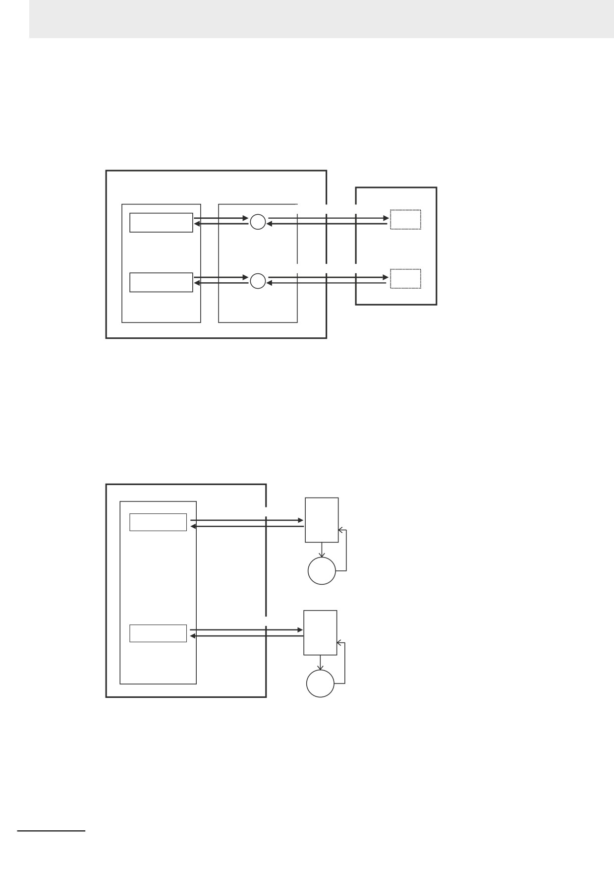
z Accessing Servo Drive, Encoder Input, and General-purpose Slaves That Are
Not Assigned to Axes
These slaves are accessed through I/O ports for device variables for EtherCAT slaves. PDO com-
munications are used to access data from I/O ports.
Controller
Example: General-purpose slave
Device variables
for EtherCAT slaves
I/O ports
PDO communications
00
Variable
InBit00
to
to
PDO communications
15
Variable
InBit15
z Accessing Servo Drive and Encoder Input Slaves That Are Assigned to Axes
Servo Drive and encode input slaves that are assigned to axes are accessed directly through the
Axis variable. PDO communications are used to access data from Axis variables.
For example, if a Servomotor is controlled with a Servo Drive, the control commands for the Servo-
motor that is assigned to an Axis variable are sent to the Servo Drive. The feedback from the Servo-
motor is sent from the Servo Drive to the Controller by using the Axis variable.
Controller
Servo Drive
System-defined variables
PDO communications
Axis variable
Servomotor
Servo Drive
PDO communications
Axis variable
Servomotor
Refer to 3-5-2 Axis Variables and Axes Group Variables for details on Axis variables.
2-14
2 NY-series Controller Operation
Precautions for Correct Use
Device variables can be assigned to the I/O ports of Servo Drive and encoder input slaves to
which axes are assigned.
The I/O port to which a device variable can be assigned must meet either of the following condi-
tions.
• The value of the R/W attribute is R (Read only).
• The value of the R/W attribute is W (Write only), and <Not assigned> is set for the process
data field under Detailed Settings on the Axis Basic Settings Display in the Sysmac Studio.
Additional Information
2
There are two types of EtherCAT communications, PDO communications and SDO communica-
tions. PDO communications are used for commands to refresh I/O data, such as data for Servo-
motor position control, on a fixed control period. SDO communications are used for commands
to read and write data at specified times, such as for parameter transfers.
Refer to the NY-series Industrial Panel PC / Industrial Box PC Built-in EtherCAT Port User's
Manual (Cat. No. W562) for details.
2-15
2 NY-series Controller Operation
2-4
Sequence Control and Motion Control
This section describes the sequence control and motion control systems that are used by the NY-series
Controller.
2-4-1
Overview of Control
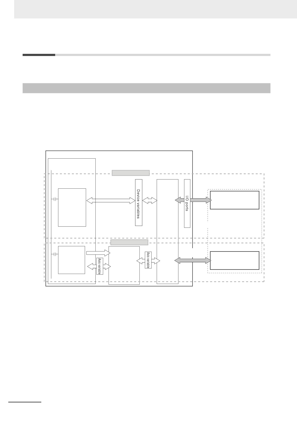
The NY-series Controller can perform both sequence control and motion control.
You execute sequence control with instructions other than motion control instructions in the user pro-
gram. Sequence control is for EtherCAT slaves that are not assigned to axes. Control is performed by
the PLC Function Module and the EtherCAT Master Function Module.
You perform motion control with motion control instructions in the user program for EtherCAT Servo
Drive and encoder input slaves that are assigned to axes. Control is performed by the PLC Function
Module, Motion Control Function Module, and the EtherCAT Master Function Module.
NY-series Controller
PLC Function Module
User program execution
Sequence control
EtherCAT slaves
Executed.
Servo Drive, encoder
Instruction
input, and general-pur-
other than
pose slaves that are not
a motion
assigned to axes
control
instruction
EtherCAT
PDO
Master
communi-
Function
cations
Module
Motion control
Executed.
EtherCAT
Motion Control
Function
communications
Motion
Servo Drive and encoder
control
Command
Module
input slaves that are
instruction
assigned to axes
Motion
control
processing
2-16
2 NY-series Controller Operation
Additional Information
Instruction Types in Terms of Control Systems
In terms of the controls, the instructions can be broadly separated into the following two types of
instructions.
Type of instruction
Definition
All instructions other than
These instructions are executed in the user program in the PLC Function
motion control instructions
Module and processing for them is completed there.
(sequence control)
Motion control instructions
These instructions are executed in the user program in the PLC Function
Module to send commands to the Motion Control Function Module.
2
MC_Home (Homing), MC_Move (Positioning), MC_CamIn (Start Cam Oper-
ation), and other instructions for motion control operations
For details on motion control instructions, refer to the NY-series Motion Control Instructions Ref-
erence Manual (Cat. No. W561). For details on other instructions, refer to the NY-series Instruc-
tions Reference Manual (Cat. No. W560).
Precautions for Correct Use
Device variables can be assigned to the I/O ports of Servo Drive and encoder input slaves to
which axes are assigned.
The I/O port to which a device variable can be assigned must meet either of the following condi-
tions.
• The value of the R/W attribute is R (Read only).
• The value of the R/W attribute is W (Write only), and <Not assigned> is set for the process
data field under Detailed Settings on the Axis Basic Settings Display in the Sysmac Studio.
If you perform the following steps, the system will clear the assignment of the device variable to
the I/O port of a Servo Drive and encoder input slave to which an axis is assigned.
(1) With the Sysmac Studio version 1.09 or higher, assign device variables to the I/O ports of
Servo Drive and encoder input slaves to which axes are assigned.
(2) Save the project data.
(3) Open the saved project data with the Sysmac Studio version 1.08 or lower.
2-17
2 NY-series Controller Operation
2-4-2
Sequence Control System
The way that the sequence control works depends on the device to control. This section describes the
operation of the function modules and the control period as part of the sequence control system.
Sequence Control System
Device
Operation of the function module
Control period
Servo Drive, encoder
• The PLC Function Module executes the user pro-
The task period of the task to
input, and general-pur-
gram and refreshes the device variables.
which the program is
pose slaves
• The EtherCAT Master Function Module exchanges
assigned (i.e., the task period
data with the slaves through the I/O ports for device
of the primary periodic task
variables.
or a periodic task)*1
*1
The data refresh period in the slave depends on settings in the slave.
Servo Drive, encoder input, and general-purpose slaves are refreshed in the process data communica-
tions cycle. This means that I/O refreshing takes place in the task period of the primary periodic task.
However, execution of the programs and refreshing of the device variables take place in the task period
of the task to which the programs are assigned. Therefore, the slave values are not reflected and not
controlled by the device variables until the task period of the task to which the programs are assigned.
If it is necessary to control a slave in the process data communications cycle, assign the program that
controls the slave to the primary periodic task.
For details, refer to 5-9-3 System Input and Output Response Times.
NY-series Controller
PLC Function Module
User program
execution
Executed.
Instruction
Servo Drive, encoder
input, and general-pur-
pose slaves
EtherCAT
Master
PDO communications
Function
Module
Sequence control period (task
I/O refreshing in the process data communi-
Data refresh
period of the primary periodic task
cations cycle (i.e., task period of the primary
period in slave
or the periodic task)
periodic task)
2-18
2 NY-series Controller Operation
2-4-3
Motion Control System
This section describes the operation of the function modules and the control period as part of the
motion control system.
z
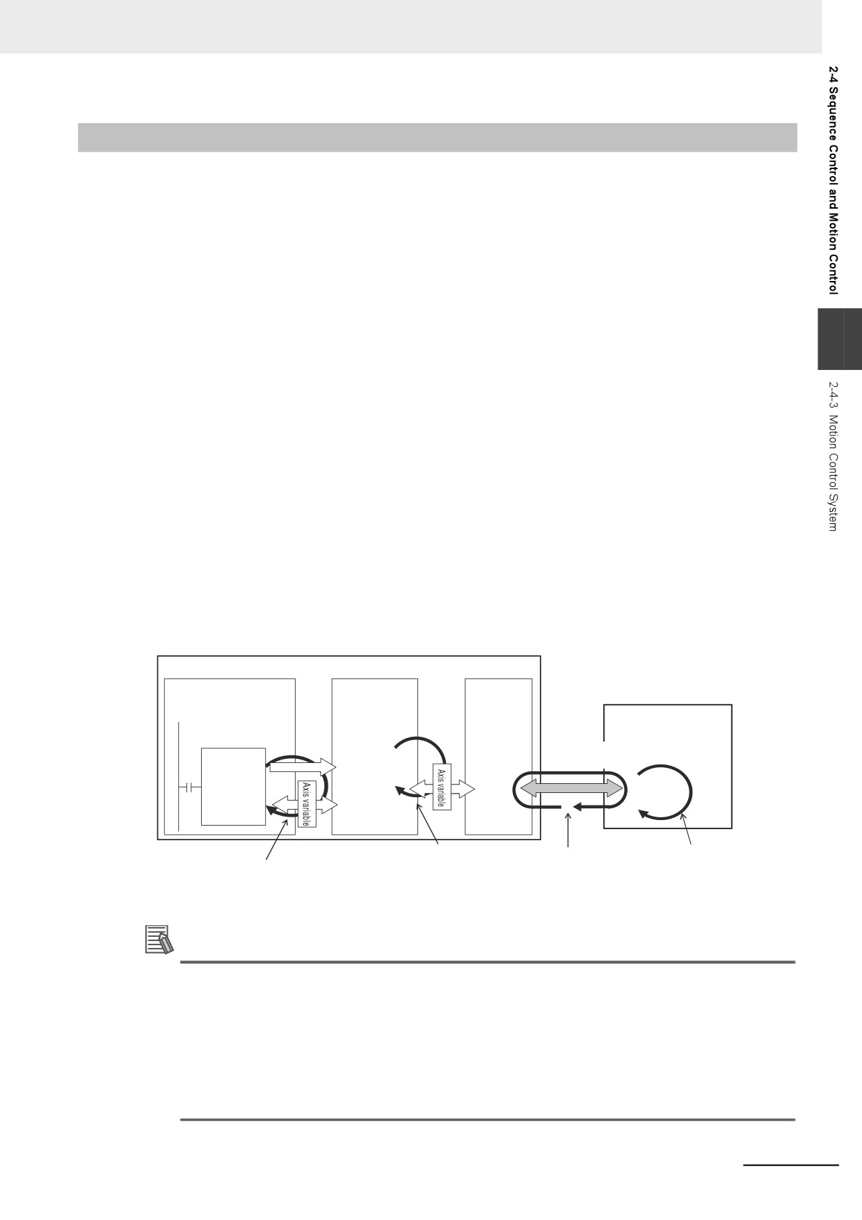
Operation of Function Modules
• The PLC Function Module executes motion control instructions in the user program and sends
commands for motion control to the Motion Control Function Module. Axis variables are used for
these commands.
• The Motion Control Function Module performs motion control processing based on commands
from the PLC Function Module. It then reflects the results of this processing in the Axis variables.
2
• The EtherCAT Master Function Module sends the command values of the Axis variable to the
Servo Drive or other slave by using EtherCAT communications.
z
Control Period
The motion control period is the task period of the primary periodic task.
Motion control processing in the Motion Control Function Module is executed in the task period of
the primary periodic task. The Motion Control Function Module also exchanges data with Servo
Drive and encoder input slaves that are assigned to the axes to control in the process data commu-
nications cycle of the primary periodic task. The process data communications cycle is synchronized
with the primary periodic task.
This makes the motion control period the same as the task period of the primary periodic task, which
allows complete synchronization of multiple axes.
However, the following restrictions apply:
• The motion control instruction is executed and the command for motion control is sent in the
sequence control period.
• The data refresh period in the EtherCAT slave depends on settings in the slave.
NY-series Controller
PLC Function Module
Motion Control
EtherCAT
Function
Master
User program execution
Module
Function
Servo Drive and encoder
Module
input slaves that are
assigned to axes
Executed.
EtherCAT
Motion
Motion
communications
control
control
processing
instruction
Command
Motion control period =
The process data communications
Data refresh
(i.e., task period of the
period in slave
Sequence control period (task period
cycle is the same as the task period
of the primary periodic task or the
primary periodic task)
of the primary periodic task.
priority-16 periodic task)
Additional Information
• You must use the Sysmac Studio to assign an axis to an EtherCAT slave to control it from the
Motion Control Function Module. This allows the PLC Function Module to send commands to
the Motion Control Function Module for motion control instructions that are executed in the
user program. It also allows the PLC Function Module to obtain information from the Motion
Control Function Module through the Axis variables.
• The task to which the program that contains the motion control instructions is assigned deter-
mines the I/O response time of the motion control system. For details, refer to 5-9-3 System
Input and Output Response Times.
2-19
2 NY-series Controller Operation
2-4-4
Synchronizing Sequence Control and Motion Control
The sequence control period is the task period of the task to which the program and I/O refreshing are
assigned. However, motion control is always executed in the task period of the primary periodic task.
The process data communications cycle for the EtherCAT slave to use for motion control is synchro-
nized with the primary periodic task.
The NY-series Controller performs motion control and process data communications for axes and axes
groups in the task period of the primary periodic task.
If you assign the sequence control program to the primary periodic task, you can synchronize the
sequence and motion control periods with the process data communications cycle for EtherCAT.
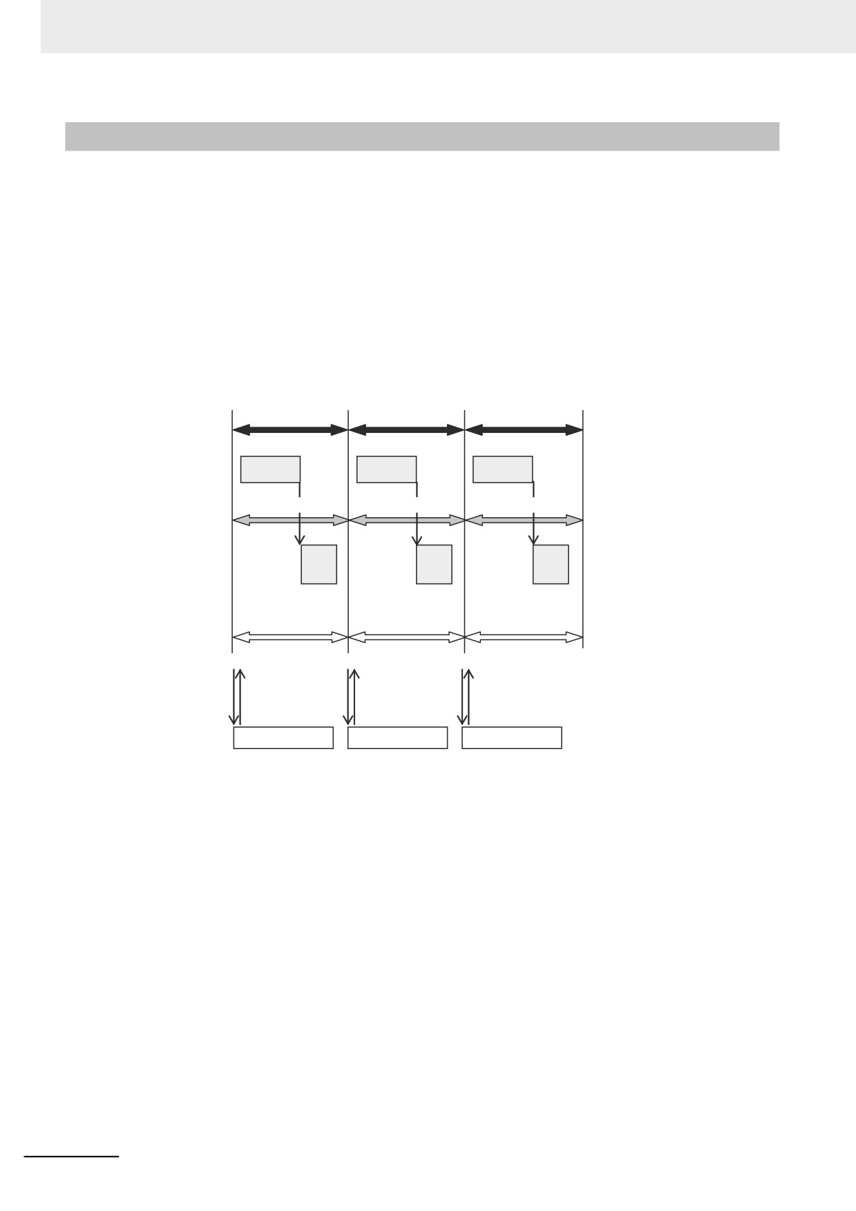
The following diagram shows a program assigned to the primary periodic task. In the following diagram,
the period of sequence control, motion control, and process data communications on EtherCAT are all
synchronized.
Sequence control
period (i.e., period of
primary periodic task)
Sequence control period
Sequence control period
User program
User program
User program
Sequence control
execution
execution
execution
Motion control period
Motion control period
Motion control period
Motion
Motion
Motion
Motion control
control
control
control
Process data
Process data
Process data
PDO communi-
communications cycle
communications cycle
communications cycle
cations on
EtherCAT
I/O refreshing
I/O refreshing
I/O refreshing
Slave/Unit
Slave/Unit
Slave/Unit
2-20
2 NY-series Controller Operation
2-5
Overview of Controller Data
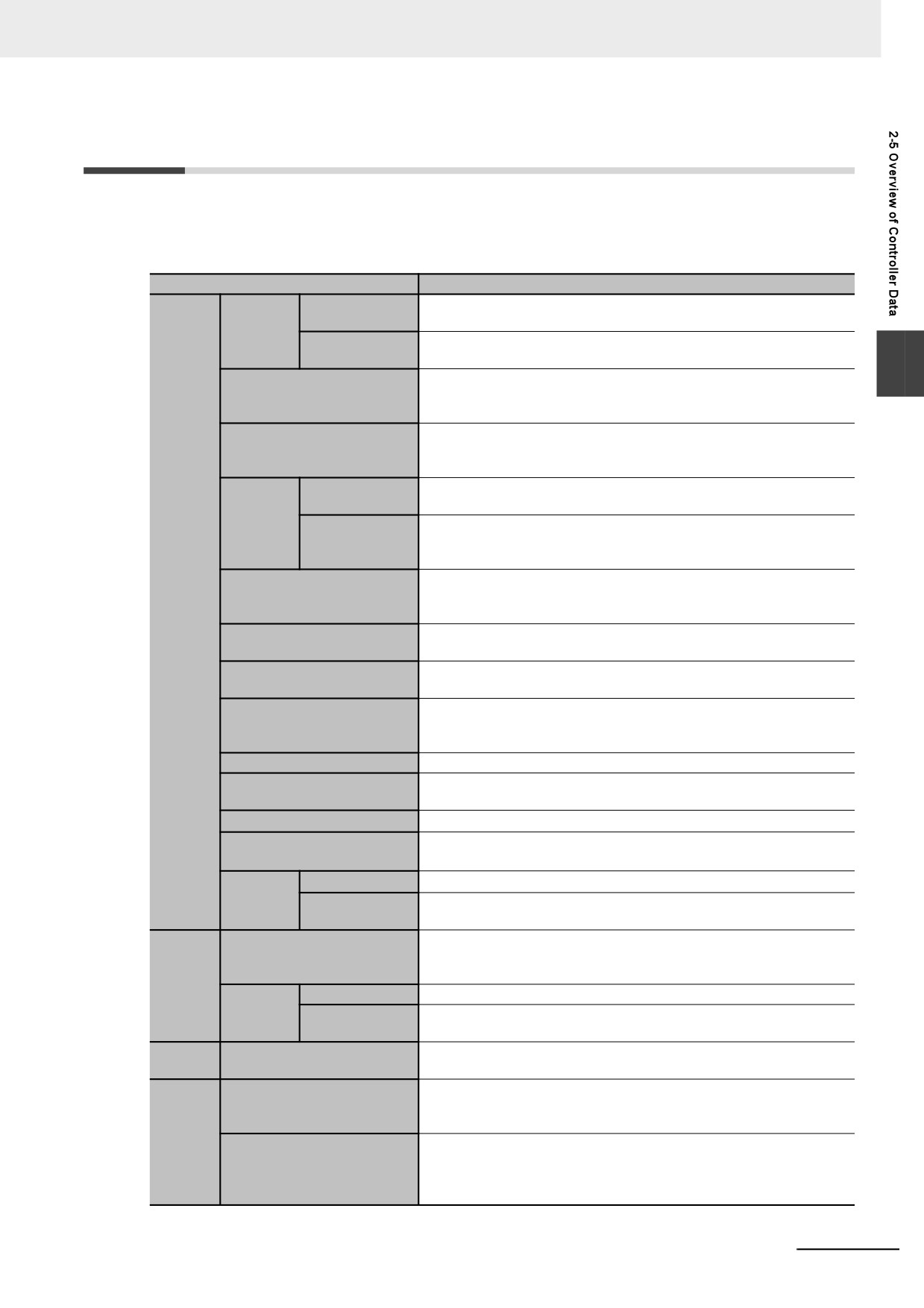
The NY-series Controller also contains settings, the user program, present values, and other data. The
main data is described in the following table.
Refer to A-5 Attributes of Controller Data for information on all of the data in the NY-series Controller.
Type of data
Description
EtherCAT Slave
This is information on the EtherCAT slave configuration.
Ether-
Configuration
CAT Con-
EtherCAT Mas-
The EtherCAT Master Settings contain parameter settings for the Eth-
figuration
ter Settings
erCAT Master Function Module, such as the communications cycle.
2
The Unit Configuration and Unit Setup contain information on the
Unit Configuration and Unit
Unit configuration that enables the Controller to recognize the Units,
Setup
and the initial settings of the Special Units.
The I/O Map contains assignment information between the variables
I/O Map
and the I/O ports that are automatically created based on the Unit
Configuration.
Operation Set-
The Operation Settings include the Startup Mode setting, Security
tings
Settings, and System Service Monitoring Settings.
Control-
Built-in Ether-
The Built-in EtherNet/IP Port Settings contain the following settings:
ler Setup
Net/IP Port Set-
TCP/IP settings, Ethernet settings, DHCP settings, DNS settings,
tings
FTP settings, and SNMP settings
The Motion Control Setup consists of settings for Axis variables and
Motion Control Setup
Axes Group variables for axis and axes groups, and motion control
Settings
parameter settings.
The cam data includes cam tables that consist of phase/displace-
Cam Data Settings
ment data for use in cam operation for motion control instructions.
These settings are for user-defined errors and user-defined informa-
Event Setup
tion.
The Task Setup contain settings for the task types, number of tasks,
Task Setup
task execution conditions, task names, programs executed in the
task, and other task settings.
Data Trace Settings
The Data Trace Settings include settings for trigger conditions.
The Tag Data Link Tables contain the tag data link settings for Ether-
Tag Data Link Tables
Net/IP.
Controller Name
The Controller name is the name of the Controller.
Operation Authority Verifi-
This data contains the operation authority passwords to perform Sys-
cation
mac Studio operations for the Controller.
Set Time
This is the time information that is used inside the Controller.
Built-in
Time Zone Set-
This is the time zone that is set for the clock in the Controller.
Clock
ting
These are the definitions of the programs, functions, and function
POUs (program organiza-
blocks. The local variable tables and the initial values of the variables
tion units)
User
are also included.
Program
Data Types
This data contains the definitions of the data types.
Data
Global Vari-
This data gives the attribute information of the global variables. It
ables
includes the Initial Value and Retain attributes.
Present
This data contains the values of the variables.
Values of Variables
Values
The event logs include the error log for the Controller, and logs of
Event Logs
events other than errors, such as when the power supply was turned
ON and OFF and when operation started.
Other
This data is used to restore the actual position of a Servo Drive with
Data
Absolute Encoder Home
an absolute encoder in motion control. The offset is the difference
Offsets
between the command position after homing and the absolute data
that is read from the absolute encoder.
2 - 21
2 NY-series Controller Operation
2-6
Operation for Controller Status
This section describes the processing that is performed for user program execution, I/O refreshing, and
external communications according to the status of the NY-series Controller. It also describes the oper-
ating modes that change the execution status of the user program when the NY-series Controller is in
the normal operation state.
2-6-1
Controller Status
The NY-series Controller can be in any of three states: startup state, normal operation state, or error
state. These states are defined as follows:
State
Definition
Startup state
The software is initializing the system.
Normal operation
The software is executing processing for instructions that are executed in a task or it is exe-
cuting a system service. A Controller error has not occurred.
Error state
A Controller error occurred when the software was executing processing for instructions
that are executed in a task or it was executing a system service.
The normal operation state has these three states for operation: PROGRAM mode, RUN mode, and
downloading. A Controller in the normal operation state changes to the other states due to user interac-
tion. This status is defined as follows:
State
Definition
PROGRAM mode
The operating mode is PROGRAM mode.
RUN mode
The operating mode is RUN mode.
Downloading
Data is being downloaded from the Sysmac Studio.
Note Refer to 2-6-3 Operating Modes for details on PROGRAM mode and RUN mode.
2-22
2 NY-series Controller Operation
z
Controller status
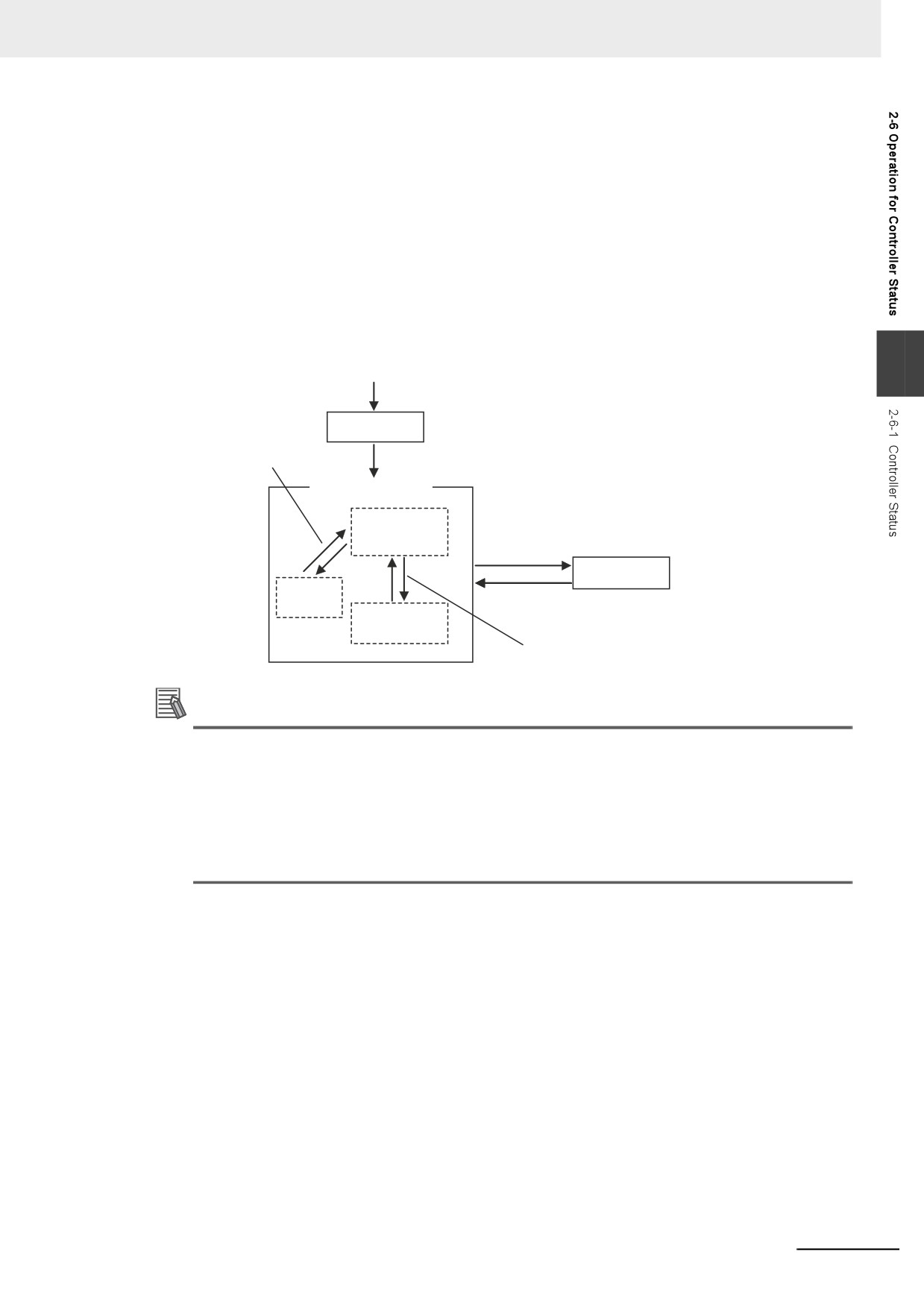
The Controller enters the startup state after the power supply is turned ON. About 10 to 20 seconds
after the Controller enters the startup state, software processing begins and the Controller changes
to normal operation. If a Controller error occurs during normal operation, the Controller changes to
the error state. When you reset the Controller error, the Controller returns to normal operation.
When the Controller changes from startup state to normal operation, it will change to the operating
mode that you specify in the Controller Setup. You can set the operating mode at startup to PRO-
GRAM mode or RUN mode. Thereafter, changing the operating mode causes the Controller to
change between PROGRAM mode and RUN mode. If you download data from the Sysmac Studio
during PROGRAM mode, the Controller will change to the downloading state. The Controller will
return to PROGRAM mode when the download is completed.
2
Power ON
Execution and comple-
Startup state
tion of data download
from the Sysmac Studio.
Software processing started.
Normal operation
PROGRAM
Controller error occurs
mode
Error state
Downloading
Controller error is reset.
RUN mode
Operating mode is changed.
Additional Information
• You can check the operating status of the Controller with the status indicators on the Industrial
Panel PC or on the Industrial Box PC. Refer to the NY-series Troubleshooting Manual (Cat.
No. W564) for troubleshooting procedures using the status indicators.
• Refer to A-5 Attributes of Controller Data for information on data operations when the Control-
ler status changes.
• Refer to 6-3-9 Changes to Variables for Status Changes for the values that variables take
when the status of the Controller changes.
2-23
2 NY-series Controller Operation
2-6-2
Operation for Controller Status
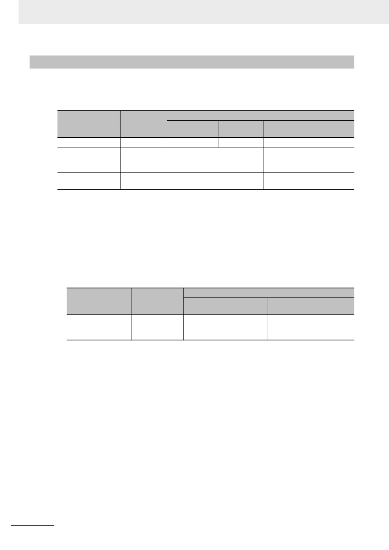
Changes in the status of the NY-series Controller affect user program execution, I/O refreshing, and the
operation of external communications. The following table shows how each process operates in startup
state and during normal operation.
Refer to the NY-series Troubleshooting Manual (Cat. No. W564) for information on the error state.
Operation
Operation during normal operation
Controller process-
during execu-
PROGRAM
ing
RUN mode
Downloading
tion
mode
User program
Stopped.
Stopped.
Executed.
Stopped.
I/O Refreshing for
Stopped.
Executed.
EtherCAT communications
EtherCAT slaves
changes to safe-operational
state. *1*2
External communica-
Stopped.
Executed.
Executed. *3
tions
*1
Only the input values are refreshed.
*2
I/O refreshing is executed when the device output hold configuration is set to enable (16#A5A5) in the _Devi-
ceOutHoldCfg (Device Output Hold Configuration) system-defined variable. Refer to Device Output Hold Con-
figurations on page 6-70 for the device output hold configurations. A Controller with unit version 1.14 or later
and Sysmac Studio version 1.18 or higher are required to use the _DeviceOutHoldCfg (Device Output Hold
Configuration) system-defined variable.
*3
The tag data links remain in effect, but the values of those links are not refreshed. The output tags retain the
values from before the download was started. The values in the input tags are not reflected in the variables.
z
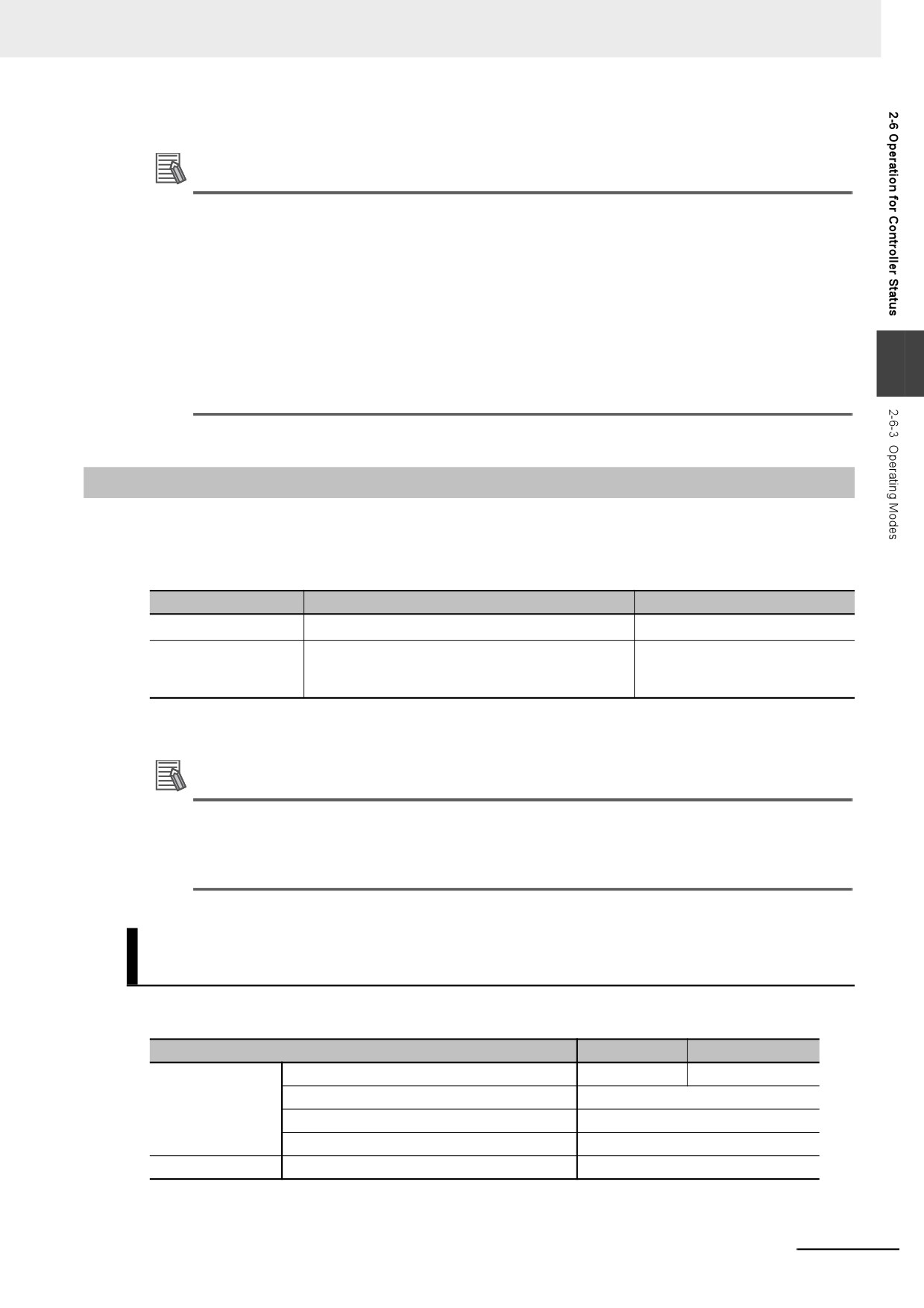
Values of Outputs in I/O Refreshing
The following table shows the values of the outputs in each state after I/O refresh processing.
Operation during normal operation
Operation
Outputs
PROGRAM
during startup
RUN mode
Downloading
mode
Outputs from Ether-
Controlled by the
The outputs have the values
Controlled by the slave set-
CAT slaves
slave settings. *1
of the device variables for
tings. *2 *3
EtherCAT slaves.
*1
Refer to the manual for each slave for information on the slave settings that apply until EtherCAT communi-
cations starts after the power supply is turned ON.
*2
When the download is completed, initialization of the EtherCAT slaves starts. When initialization is in prog-
ress, the outputs reflect the settings for the slave.
*3
Device outputs are retained even when the operating mode changes or when downloading if the device
output hold configuration is set to enable (16#A5A5) in the _DeviceOutHoldCfg (Device Output Hold Con-
figuration) system-defined variables. Refer to 6-3-9 Changes to Variables for Status Changes for details. A
Controller with unit version 1.14 or later and Sysmac Studio version 1.18 or higher are required to use the
_DeviceOutHoldCfg (Device Output Hold Configuration) system-defined variable.
Refer to 6-3-8 Variable Attributes for information on the Initial Value attribute for variables.
Refer to Device Output Hold Configurations on page 6-70 for details on the device output hold con-
figurations.
2-24
2 NY-series Controller Operation
Additional Information
Servo Drive Response to Changes in Operating Mode
If the operating mode changes from RUN to PROGRAM mode during a motion control operation,
the axes will decelerate to a stop at the maximum deceleration rate.
Changing the Operating Mode during Initialization of EtherCAT Slaves
You can change the operating mode of the Controller to RUN mode while EtherCAT slaves ini-
tialization is in progress. If you do, provide programming to confirm that communications are
established before you attempt to use slave data in control operations. Your program can use the
2
_EC_PDSlavTbl (Process Data Communicating Slave Table) system-defined variable to see if
the process data inputs and outputs are valid for all of the slaves.
2-6-3
Operating Modes
You can change the operating mode according to the purpose of operation, such as functional testing or
actual operation. You can set the operating mode to RUN mode or PROGRAM mode, depending on the
purpose. The execution status of the user program is different in each operating mode. The following
table gives the purpose for each operating mode and the execution status of the user program.
Operating mode
Application
User program execution status
RUN mode*1
RUN mode is for trial operation or actual operation.
Executed.
PROGRAM mode
PROGRAM mode is for checking I/O wiring and
Not executed.
other functional testing without executing the user
program.
*1
For the default setting, the Controller will enter RUN mode when the Controller changes from startup state to
normal operation.
Additional Information
The Controller performs various operations when the operating mode is changed, i.e., the axes
are stopped, and motion control instructions are aborted. For details on how the Motion Control
Function Module operates when the operating mode is changed, refer to the NY-series Motion
Control Instructions Reference Manual (Cat. No. W561).
Operations Allowed from the Sysmac Studio or an HMI in Each
Operating Mode
The major operations that you can perform from the Sysmac Studio or an HMI in each operating mode
are listed in the following table.
Operation
RUN mode
PROGRAM mode
Sysmac Studio
Synchronization
Not possible.
Possible.
Online editing
Possible.
Forced refreshing
Possible.
Changing the values of variables
Possible.
HMI
Changing the values of variables
Possible.
2-25
2 NY-series Controller Operation
Retention of Variable Values during Changes in Operating Mode
The following table shows how the Retain attribute affects the variable values when the operating mode
is changed between RUN mode and PROGRAM mode.
Retain attribute of
Values of variables
variable
Non-retain
If initial values are set, the variables change to the initial values.
If no initial values are set, the variables change to the system-defined initial values.*1
Retain
The values before the operating mode changed are retained.
*1
The system-defined initial values of variables depend on the data types of the variables. Refer to When the Ini-
tial Value Specification Is Left Blank on page 6-65.
Refer to 6-3-9 Changes to Variables for Status Changes for the values that variables take when the sta-
tus of the Controller changes.
Setting and Changing the Operating Mode
When operation starts after the power supply is turned ON, the Controller operates in the operating
mode that you specify in the Controller Setup. During normal operation, you change the operating
mode for different purposes. You use the Sysmac Studio to set and change the operating mode.
z Operating Mode Setting after the Power Supply Is Turned ON
When the Controller starts operating after the power supply is turned ON, the Controller operates in
the operating mode that you set as the Startup Mode. Specify RUN mode or PROGRAM mode in the
Startup Mode setting in the Operation Settings in the Controller Setup. Refer to 4-2-2 Controller
Setup for details on the Startup Mode setting.
z Changing the Operating Mode during Operation
You can change the operating mode from the Sysmac Studio. Select the RUN mode or PROGRAM
mode from Controller - Operating Mode on the menu bar.
Precautions for Correct Use
Always confirm the safety of the controlled system before you change the setting of the Startup
Mode or the current operating mode.
2-26
2 NY-series Controller Operation
Checking the Operating Mode
You can check the operating mode with the RUN indicator on the Industrial PC or the Sysmac Studio.
z Checking the RUN Indicator
The RUN indicator on the Industrial PC indicates the operating mode as given below.
RUN indicator
Operating mode
status
Not lit
PROGRAM mode
Lit
RUN mode
2
z Checking the Operating Mode from the Sysmac Studio
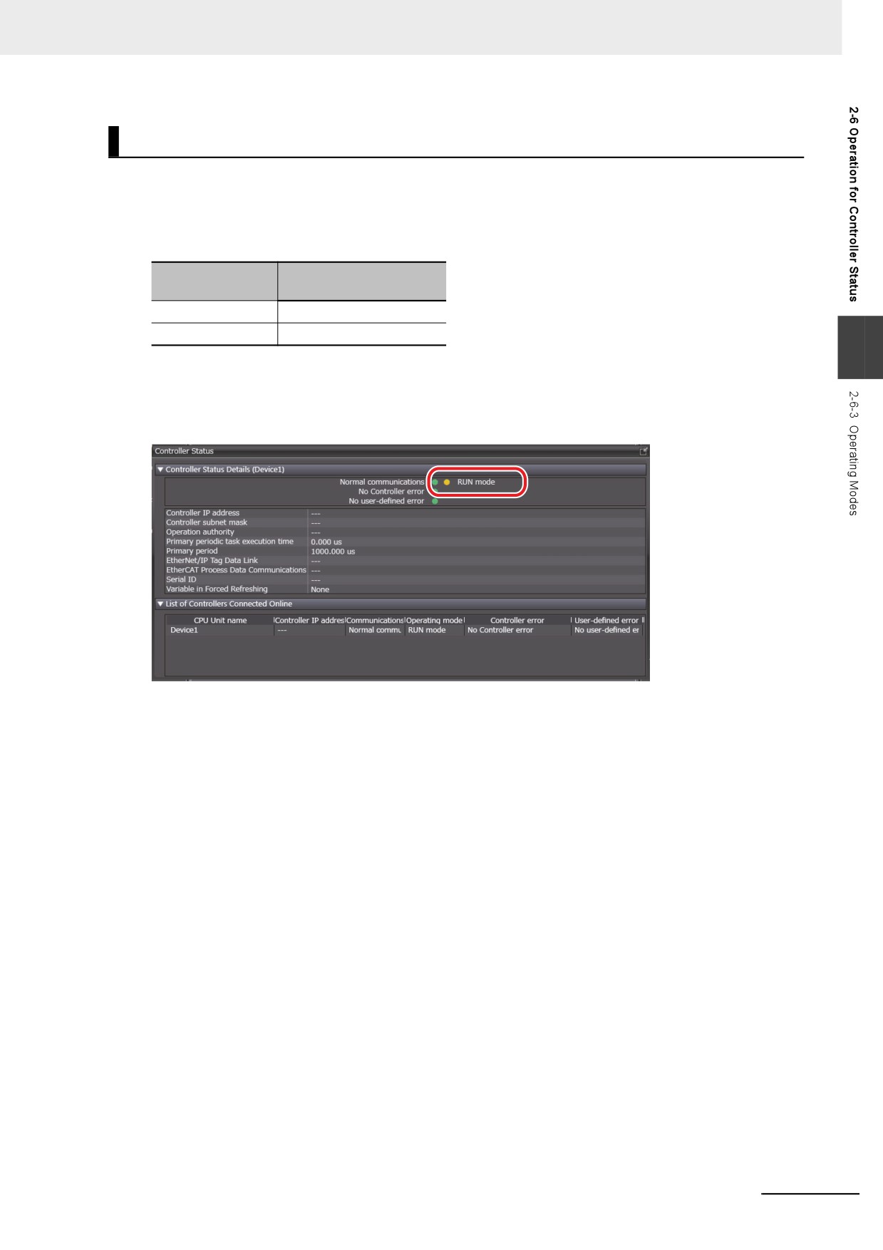
You can check the operating mode from the Controller Status Pane of the Sysmac Studio. The fol-
lowing Controller Status Pane indicates that the Controller is in RUN mode.
2-27
2 NY-series Controller Operation
2-7
Monitoring and Changing Windows
Status
In an NY-series Controller, you can monitor and change the status of Windows from the Controller.
2-7-1
Windows Status
The following table describes five states of Windows installed in an NY-series Controller.
State
Description
Booting
Windows is starting up.
Running
Windows is running.
ShuttingDown
Windows is shutting down.
Halted
Windows is stopped.
(Processing to shut down Windows is completed and Windows is not running.)
Error
An error occurred in Windows.
Additional Information
You can use the system-defined variables or instructions to identify the status of Windows.
Running, Halted, and Error states can be identified. Booting and ShuttingDown states cannot be
identified.
2-7-2
Monitoring Windows Status
You can use the system-defined variables or instructions to monitor Windows status.
System-defined Variables Related to Monitoring of Windows Status
Of the states of Windows, Running, Halted, and Error states are indicated with the system-defined vari-
ables.
Refer to Functional Classification: OS (Windows) on page A-62 for details on system-defined variables.
Variable name
Meaning
Function
Data type
R/W
_OSRunning
OS Running Flag
TRUE when the Controller observes that OS
BOOL
R
(Windows) is running.
_OSHalted
OS Halted Flag
TRUE when the Controller observes that OS
BOOL
R
(Windows) is stopped.
_OSErrorState
OS Error State Flag
TRUE when the Controller determines that an
BOOL
R
error occurred in OS (Windows).
2-28
2 NY-series Controller Operation
Instructions Related to Monitoring of Windows Status
The following instruction is supported to monitor Windows status.
Refer to the NY-series Instructions Reference Manual (Cat. No. W560) for details on the instruction.
Instruction
Instruction name
Introduction
IPC_GetOSStatus
Read OS Status
Reads OS (Windows) status. Of the states of Windows,
Running, Halted, and Error states are read.
2-7-3
Changing Windows Status
2
You can use the instructions to change Windows status.
Instructions Related to Changing of Windows Status
The following instructions are supported to change Windows status.
Refer to the NY-series Instructions Reference Manual (Cat. No. W560) for details on the instructions.
Instruction
Instruction name
Introduction
IPC_RebootOS
Restart OS
Restarts OS (Windows).
IPC_Shutdown
Shut Down
Notifies the shutdown request to OS (Windows).
2-7-4
Changes in Windows Status
Windows status changes to Booting when an Industrial PC is started. Windows status changes to Run-
ning when the startup is ended.
If power is not provided due to the IPC_Shutdown instruction, a UPS power interruption detection, or
other reasons, or the power supply button is pressed while Windows is running, Windows status
changes to ShuttingDown. Windows status changes to Halted when the shutdown is ended.
Or, if the IPC_RebootOS instruction is executed while Windows is running, Windows status changes to
ShuttingDown. Windows status changes to Booting when the shutdown is ended and changes to Run-
ning when the startup is ended.
Also execute the IPC_RebootOS instruction to recover from Error state.
If Windows status changes to Running, Halted, or Error, Controller events that indicate the changes are
recorded.
However, if Windows status does not change to Halted even the time specified in the OS of the Shut-
down Wait Time Setting is elapsed from the Controller notifies the shutdown request to Windows by
executing the IPC_Shutdown instruction, a Controller event is not recorded.
2-29
2 NY-series Controller Operation
2-8
Shutdown
You must connect a UPS (uninterruptible power supply) to an NY-series Industrial PC. By connecting a
UPS, even if an unexpected lose of power (i.e., a power interruption) occurs, the shutdown can be
properly performed to prevent data or file loss.
When the system-defined variable that indicates a power interruption detection in the UPS or a press-
ing of the power supply button changes to TRUE, the processing prepared for a power interruption can
be executed in the user program of the Controller.
Program the following processing as required.
• Copy the variables without a Retain attribute that are used in the user program of the Controller to
variables with a Retain attribute.
• Stop the file operations for the Virtual SD Memory Card in the Controller.
• Safely stop the operation of motion control during execution in the Controller.
After the processing in the user program is completed, the Controller system executes the shutdown
such as a holding of variables with a Retain attribute and other processing. If the shutdown in the Con-
troller is completed, the Controller notifies the shutdown request to Windows.
In Windows, the notification from the Controller is used as a trigger and the shutdown such as an appli-
cation end and other processing can be executed.
Refer to Details on Shutdown on page 2-34 for details on shutdown.
Precautions for Correct Use
• If a UPS is not connected or the battery voltage of a UPS is dropped, the shutdown at the
power interruption is not executed. Therefore, variables with a Retain attribute, absolute
encoder home offsets, and event logs cannot be retained.
• Select a UPS with a battery capacity that the backup time is longer than the shutdown time of
the Controller and Windows. The shutdown is not normally ended if the battery backup time is
short.
Additional Information
Refer to the NY-series Industrial Panel PC Hardware User’s Manual (Cat. No. W557) or the NY-
series Industrial Box PC Hardware User’s Manual (Cat. No. W556) for how to connect a UPS.
2-30
2 NY-series Controller Operation
2-8-1
Processing When Power Is Interrupted or Power Supply Button Is
Pressed
This section describes the processing of the Controller when power is interrupted, the power supply
button is pressed, or the IPC_Shutdown instruction is executed while the Controller is operating. The
processing is different according to the UPS connection or the time to press the power supply button.
Operation
UPS connection
Controller processing
Power is interrupted.
A UPS is connected.
The signal from a UPS is used as a trigger and the
shutdown is executed. *1 *2
A UPS is not connected or
The shutdown is not executed. *3
2
the UPS battery voltage is
dropped.
The power supply button is
---
A pressing of the power supply button is used as a
pressed within 5 seconds.
trigger and the shutdown is executed. *1 *2
The IPC_Shutdown instruc-
---
The Controller system executes the shutdown. *1
tion is executed.
The power supply button is
---
A forced shutdown is started. The shutdown is not
pressed in 5 seconds or
executed. *3
more.
*1
Refer to 2-8-3 Contents of Shutdown for information on shutdown.
*2
The Controller system executes the shutdown by executing the IPC_Shutdown instruction or when the time
that is specified in the User program of the Shutdown Wait Time Setting is elapsed.
*3
If the shutdown is not executed and the power supply is turned ON next time, an Event Log Save Error obser-
vation event or a Present Values of Retained Variables Not Saved major fault event will occur.
Also, the following will happen to data in the Controller.
Values of variables with a Retain attribute and absolute encoder home offsets will be the values that the power
supply is turned ON previously.
Event logs from the previous startup until the shutdown is not executed are disappeared.
Additional Information
If you press the power supply button when the Controller is not operated, the normal mode of an
Industrial PC is started. Press the power supply button in a disconnection status of the power
connector, connect the power connector while pressing the power supply button, and 10 sec-
onds is elapsed, the Controller starts operation in PROGRAM mode no matter the Startup Mode
setting in the Controller Setup.
In this case, a Safe Mode observation event will occur.
Refer to the NY-series Industrial Panel PC / Industrial Box PC Setup User's Manual (Cat. No.
W568) for information on startup and end.
2-31

2 NY-series Controller Operation
2-8-2
Settings of Shutdown
Set the following parameters in the Controller Setup.
Changes
Setting
Update
Parameter
Description
Set value
Default
in RUN
group
timing
mode
Shutdown
User pro-
Sets the time to wait when the
1 to 30 s
5 s
When
Not
Wait Time
gram
signal is ON from a UPS which
down-
allowed.
Setting
indicates a power interruption
loaded to
detection, or when a shutdown
Controller
command is accepted by press-
ing the power supply button until
the Controller starts the shut-
down.
OS
Sets the time to wait when the
30 to 300 s
60 s
When
Not
Controller notifies the shutdown
down-
allowed.
request to Windows until the
loaded to
shutdown completion is detected
Controller
in Windows.
z
User Program
The signal from a UPS which indicates a power interruption detection is monitored in the user pro-
gram of the Controller. The signal from a UPS is used as a trigger and the processing prepared for a
power interruption is executed in the user program.
The Controller system waits the completion of processing in the user program only for the time that
is specified in the User program setting. Therefore, specify a time in the User program setting
which is longer than the processing time in the user program. If the specified time is short, the pro-
cessing in the user program will be interrupted.
z
OS
If the shutdown in the Controller system is completed, the Controller system notifies the shutdown
request to Windows. In Windows, the notification from the Controller is used as a trigger and the
shutdown such as an application end and other processing can be executed.
According to the Controller system monitors the status in Windows, the normal shutdown completion
in Windows can be detected.
When the shutdown in Windows is completed before the time specified in the OS setting, a Control-
ler event that indicates the state is changed to Halted is recorded. Therefore, specify a time in the
OS setting which is longer than the processing time in Windows. If the specified time is short, the
processing in Windows will be interrupted and applications in Windows cannot be normally ended.
If a Controller event that indicates the state is changed to Halted is not recorded, the time specified
in the OS setting may be shorter than the processing time in Windows.
2-32
2 NY-series Controller Operation
2-8-3
Contents of Shutdown
When a UPS power interruption is detected or the power supply button is pressed, the system-defined
variable which corresponds to each status changes to TRUE. By monitoring the status of these system-
defined variables, it is possible to copy the necessary data to variables with a Retain attribute and
safely stop the operation of motion control during execution. A monitoring of the system-defined vari-
ables and processing prepared for a power interruption are created in the user program of Controller.
Execute the IPC_Shutdown instruction after the completion of processing prepared for a power inter-
ruption in the user program.
The Controller system performs the shutdown by executing the IPC_Shutdown instruction.
2
System-defined Variables That Are Used As Triggers of Shutdown
The following table gives the system-defined variables that are used as triggers to start the processing
in the user program.
Variable name
Meaning
Function
Data type
R/W
_SelfTest_UPSSignal
UPS Signal Detection
TRUE when a temporary power interruption signal
BOOL
R
Flag
from UPS is detected.
_RequestShutdown
Request Shutdown
TRUE when the power supply button is pressed
BOOL
R
Flag
while running.
Refer to Functional Classification: Power Supply on page A-60 for details on system-defined variables.
Instructions That Notify Shutdown Requests
The following table gives an instruction that is used to notify the processing completion in the user pro-
gram to the Controller system and notify the shutdown request from the Controller system to Windows.
Instruction
Instruction name
Introduction
IPC_Shutdown
Shut Down
Starts the shutdown in the Controller system and noti-
fies the shutdown request to Windows after the shut-
down is completed.
Refer to the NY-series Instructions Reference Manual (Cat. No. W560) for details on the instruction.
2-33
2 NY-series Controller Operation
Details on Shutdown
The following describes the details on the shutdown in any of three states of the Controller: RUN mode,
PROGRAM mode, or startup state.
z RUN Mode
The user program in the Controller is executed.
In RUN mode, a monitoring of the system-defined variables and processing prepared for a power
interruption created in the user program are executed to prevent loss of operation data in the equip-
ment managed in the Controller. The Controller system performs the shutdown after the processing
in the user program is completed. Then, the shutdown such as an application end and other pro-
cessing is executed in Windows.
The following describes the details of shutdown in RUN mode.
1 Monitor the
_SelfTest_UPSSignal
(UPS Signal Detection Flag) and
_RequestShutdown
(Request Shutdown Flag) system-defined variables in the user program.
2 When the _SelfTest_UPSSignal (UPS Signal Detection Flag) or _RequestShutdown (Request
Shutdown Flag) system-defined variable changes to TRUE, execute the processing prepared
for a power interruption in the user program as required.
3 Execute the IPC_Shutdown instruction in the user program after the completion of processing
prepared for a power interruption.
• The Controller system starts the shutdown when the IPC_Shutdown instruction is executed.
• Values of variables with a Retain attribute, absolute encoder home offsets, and event logs are
retained.
• The Controller notifies the shutdown request to Windows and Windows starts the shutdown.
• Even if the IPC_Shutdown instruction is not executed, the Controller system starts the shut-
down when the time that is specified in the User program of the Shutdown Wait Time Set-
ting is elapsed.
• When the shutdown in Windows is completed, a Controller event that indicates Windows sta-
tus changes to Halted is recorded.
However, if Windows status does not change to Halted even the time specified in the OS of
the Shutdown Wait Time Setting is elapsed from the Controller notifies the shutdown
request to Windows, a Controller event is not recorded.
• If the signal from a UPS is used as a trigger and the shutdown is started, the Power Status
Output of the I/O connector on the Industrial PC turns ON after the shutdown is completed.
• The UPS stops providing power when the Power Status Output turns ON.
2-34
2 NY-series Controller Operation
z
PROGRAM Mode
The user program in the Controller is not executed.
In PROGRAM mode, the processing prepared for a power interruption in the user program is not
necessary because the Controller does not perform control operations in the equipment.
The shutdown such as an application end and other processing is executed in Windows after the
Controller system completes the shutdown.
The following describes the details of shutdown in PROGRAM mode.
• When the _SelfTest_UPSSignal (UPS Signal Detection Flag) or _RequestShutdown (Request Shut-
down Flag) system-defined variable changes to TRUE, the Controller system immediately starts the
shutdown.
2
• Values of variables with a Retain attribute, absolute encoder home offsets, and event logs are
retained.
• The Controller notifies the shutdown request to Windows and Windows starts the shutdown.
• When the shutdown in Windows is completed, a Controller event that indicates Windows status
changes to Halted is recorded.
However, if Windows status does not change to Halted even the time specified in the OS of the
Shutdown Wait Time Setting is elapsed from the Controller notifies the shutdown request to
Windows, a Controller event is not recorded.
• If the signal from a UPS is used as a trigger and the shutdown is started, the Power Status Output
of the I/O connector on the Industrial PC turns ON after the shutdown is completed.
• The UPS stops providing power when the Power Status Output turns ON.
z
Startup State
The Controller is initializing the system.
In startup state, the processing prepared for a power interruption in the user program is not neces-
sary because the Controller does not perform control operations in the equipment.
The shutdown such as an application end and other processing is executed in Windows after the
Controller system completes the shutdown.
The following describes the details of shutdown in startup state.
• When the _SelfTest_UPSSignal (UPS Signal Detection Flag) or _RequestShutdown (Request Shut-
down Flag) system-defined variable changes to TRUE, the Controller system immediately starts the
shutdown.
• Values of variables with a Retain attribute, absolute encoder home offsets, and event logs are
retained.
• The Controller notifies the shutdown request to Windows and Windows starts the shutdown.
• When the shutdown in Windows is completed, a Controller event that indicates Windows status
changes to Halted is recorded.
However, if Windows status does not change to Halted even the time specified in the OS of the
Shutdown Wait Time Setting is elapsed from the Controller notifies the shutdown request to
Windows, a Controller event is not recorded.
• If the signal from a UPS is used as a trigger and the shutdown is started, the Power Status Output
of the I/O connector on the Industrial PC turns ON after the shutdown is completed.
• The UPS stops providing power when the Power Status Output turns ON.
2-35
2 NY-series Controller Operation
2-9
Resetting the Controller
The Controller can be reset only by resetting the Controller from the Sysmac Studio or Industrial PC
Support Utility.
z Resetting the Controller from the Sysmac Studio
The Controller can be reset when the operating mode of the Controller is PROGRAM mode.
Refer to the Sysmac Studio Version 1 Operation Manual (Cat. No. W504) for information on reset-
ting the Controller from the Sysmac Studio.
z Resetting the Controller from the Industrial PC Support Utility
The Controller can be reset when the operating mode of the Controller is PROGRAM mode.
Refer to the NY-series Industrial Panel PC / Industrial Box PC Setup User’s Manual (Cat. No. W568)
for information on resetting the Controller from the Industrial PC Support Utility.
2-36