Haima S5 1.5T. Service Manual - part 8
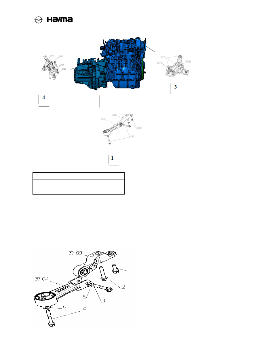
Engine Suspension
1G-3
1 Engine1#
suspension
3 Engine3#
suspension
4 Engine4#
suspension
1.1.1 Engine1# Suspension Bracket Dismantling/ Mounting
1. Dismantle the engine # 1 bracket bolts 1 and 2 (transmission side) ;
2. Remove the engine mounts bolt # 1 flat washer 5 ,3, 4 flat washers and bolts to remove the engine 1# 6;
3. Check rubber mounts broken, hardening or damage.
4. Mount parts according to the sequence reverse to the dismantling process.