Iran Khodro Pars. Service Manual - part 8
-------------------------------------------------------------------------------------------------------------------------------------------------------------
118
5
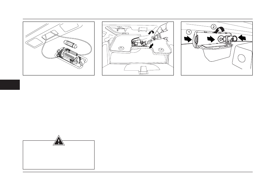
CHANGING LAMPS
LED trunk
Insert carefully a screwdriver into the groove
of the lights. Removing the talc, the lamp can
be seen. Detach the lamps from both ends of
your connection replace the bulb. Re-install the
lights in place.
Dashboard lights
- First, by opening two bolts, open the
frame of lights.
-Then by rotating the base of lamp
anti clockwise open the base of lamp
and replace it.
The third red light
-First, open the holding frame of lights by
pressing two buttons on either side of the
frame. (1)
-Then, by pressing the bulb inward and
rotate it counterclockwise to open and replace
the bulb. (2)
WARNING
The bulbs are under vacuumed and, at
the time of replacing may be broken and
cause injuries.