Yanmar diesel tractor EF494T. OPERATOR'S MANUAL - part 12


  Index      Tractors     Yanmar diesel tractor EF494T. OPERATOR'S MANUAL


Search            


Content   ..  10  11  12  13   ..


Yanmar diesel tractor EF494T. OPERATOR'S MANUAL - part 12


EF494T OM 

44 

17. Hydraulic 

output 


CAUTION


Never fail to stop the engine before trying to detach the 
hydraulic plug or pipes. Otherwise, you may be injured 
by high pressure oil. 
 

Single action cylinder (e.g. dump trailer) 

 
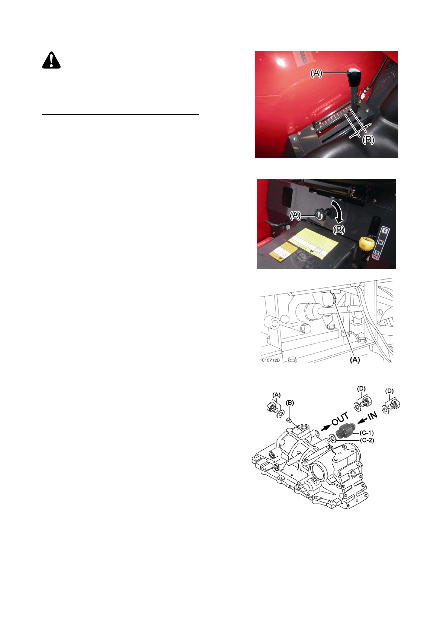
(1) Set the position control lever about 20 mm below the 

top position.  

 
(A) Position control lever  
(B) About 20 mm  


(2) Fasten the hydraulic stop slow-return valve fully 

clockwise. 

  
(A) Hydraulic stop slow-return valve  
(B) Close 


(3) Remove the hydraulic output plug, and connect the 

high pressure hose of an implement. 
* Keep removed copper packing and plugs.  

 
(A) Hydraulic output plug 
 

NOTE: 

3-point rear hitch implement cannot be controlled 

by position control lever while stop slow-return 
valve is closed. 


Double action cylinder  

 
(1) Remove the plug (A).  Insert and tighten the screw 

plug (B) to switch inner hydraulic oil flow. 

(2) Remove plugs (D) on the right side of hydraulic 

housing.  Put the filter adapter (C) to the return port 
(IN).  Connect the hydraulic valve of implement. 


Port at the front side: OUT (to take out) 
Port at the rear side: IN (to return) 
 
(A) Plug, 3/4-16UNF 
(B) Screw plug, PTF 1/4-18 (198245-42160) 
(C-1) Filter adapter, 3/4-16UNF (1A7780-45950) 
(C-2) Gasket, 19x1.0 (23414-190000) 
(D) Plug, 3/4-16UNF 


NOTE: 

Rear hitch implement can be controlled by position 
control lever. 
Keep plug (D) for future reuse. 


EF494T OM 

45 

18. 

Using 3-point link 

(1) Mount the lower link on the lower link hinge and fix it 

with a lock pin.  


Left and right links are commonly usable, but note 
the front and rear position. Mount the link so that the 
link mounting hole comes backward. 

 
(A) Lower link  
(B) Lift link mounting holes 


(2) Fix the check chain on the chain bracket and the 

lower link mounting holes (rearmost). Foremost 
holes are used for coupling the lift link.  

 
(A) Check chain bracket  
(B) Check chain 


(3) Couple the lift link with the lift arm and the lower link.

 
(A) Lift link  
(B) Lower link  


(A) Lift link hole  
(B) Lower link hole: Not possible to use 
(C) Lower link hole: Standard 
(D) Lower link hole  
(E) Check chain  
(F) Lower link separation 


EF494T OM 

46 

*Identify the left and right lift links. Mount the 

adjustable one to the right and the fixed one to the 
left. 

 
(A) Left lift link (Fixed)  
(B) Right lift link (Adjustable) 


(4) Install the top link at the top link hinge hole.  
 

Chose (A) or (B) or (C) depending on the implement.


19. 

Adjusting top link 

Loosen the lock nut for the top link and turn the 
turnbuckle to adjust the length of the top link. When an 
implement is not used, hang the top link on the hook. 
 

(A) Hook  
(B) Lock nut  
(C) Top link 


IMPORTANT 


Install the top link lock nut (B) on the implement side. If 
the lock nut were to be mistakenly installed on the 
opposite side, it will cause the top link to be damaged.


EF494T OM 

47 

20. 

Mounting general farm implements 

(1) Adjust the length of the right lift link to make the left 

and right lower links equal in height.  

 
(A) Lower link  
(B) Lift link 


(2) Align the center of the tractor with the center of the 

implement on the flat ground.  

(3) Fix the left lower link on the implement, then fix the 

right lower link. If the right lower link pinhole is out of 
position, turn the lift link to bring the hole in the 
position.  

(4) Fix the standard top link on the top link hinge using 

the ball socket lock pin. Next, loosen the top link lock 
nut and turn the turnbuckle. Lock the implement with 
the lock pin.  


(5) Loosen the lock nut of the top link and turn the 

turnbuckle for adjustment. Fix the implement in the 
top link mounting position with a pin. 


(A) Top link  
(B) Top link hinge 
(C) Right lift link 


(6) Lower the implement on the ground. Adjust its 

posture with the top link turnbuckle.  

(7) To install an implement requiring the drive force, 

follow the instruction on the nameplate mounted on 
the safety cover for the drive shaft. 

(8) Lift the implement slightly and make sure it is level. If 

not, adjust the right lift link.  

(9) Lift the implement to a maximum height and rotate it 

with a hand. If it is hard to rotate with a hand or if the 
rotation is not smooth, adjust the length of the top 
link.  


Content   ..  10  11  12  13   ..