Yanmar diesel tractor EF494T. OPERATOR'S MANUAL - part 13
EF494T OM
48
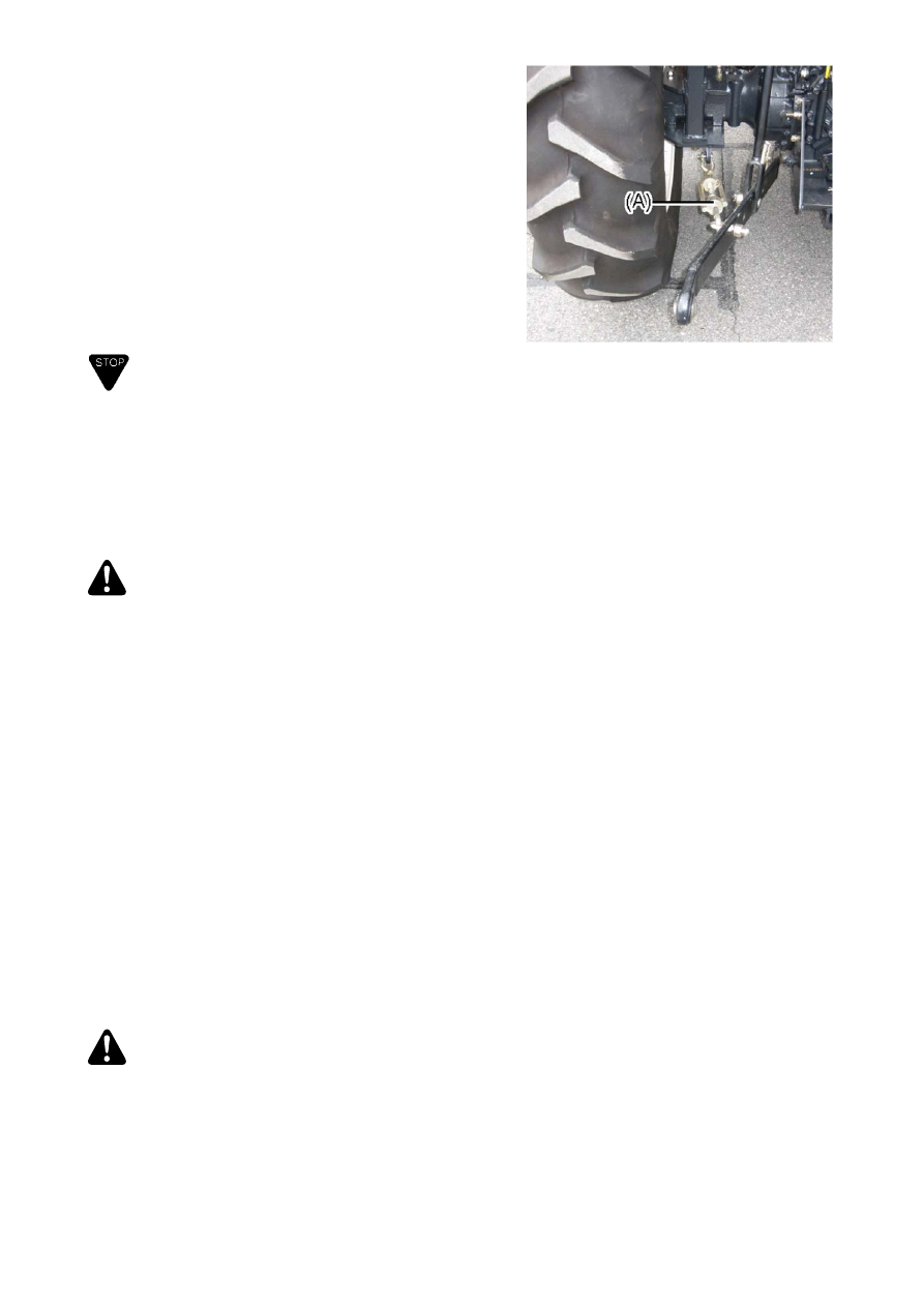
(10) Check chains
Adjust check chains (A).
1) For use of implements such as a plough, harrow and
subsoil, adjust check chains (A) so that an
implement can move 5 - 6 cm to right and left.
Prevent an implement from swinging to hit against
the wheels and tires.
2) For use of implements such as a rotary tiller and
mower, adjust check chains (A) so that an
implement can move 1cm to right and left.
(11) Dismantling is done in the reverse order as the
fixing process.
IMPORTANT
Remove the drawbar if the drawbar interferes with an
implement.
Fasten lower links to prevent from swinging to hit
against wheels and tires when driving the tractor
without an implement.
21.
Notes on using service implement
WARNING
When moving the tractor to mount an implement, never allow a
person or persons between the tractor and the implement.
Mount or dismantle an implement on a flat ground using a safe
method. Use the lighting during nighttime works.
When a heavy implement is mounted on the tractor, apply a
counterbalance to maintain a balanced condition.
Before leaving the tractor for mounting an implement, never fail
to engage the parking brake and stop the engine. Make sure the
PTO shift lever is in N.
For traction work, always use the draw bar. Do not attach to
other parts of the tractor.
Use a wider wheel span for a traction work or works on the
slope.
Do not operate the low speed machines at a higher speed than
the rated. Maintain the rated PTO speed.
When drawing a trailer, interlock the trailer brake with the tractor
brake. Do not change the shift on the slope.
Mounting an implement machine results in a considerable overall
length; be careful not to hit farmers or constructions in the
vicinity.
Negligence of safety precautions may cause serious injury
or death.
WARNING
Running the PTO speed below or above the rated operating speed of
the implement may cause damage to the tractor or the implement.