Yamaha XV1700P, XV1700PC. Service Manual - part 13
4 - 17
CHAS
REAR WHEEL, BRAKE DISC, AND REAR WHEEL
PULLEY
EAS00561
REMOVING THE REAR WHEEL
1. Stand the motorcycle on a level surface.
WARNING
_
Securely support the motorcycle so that
there is no danger of it falling over.
NOTE:
_
Place the motorcycle on a suitable stand so
that the rear wheel is elevated.
2. Remove:
• brake caliper
NOTE:
_
Do not depress the brake pedal when remov-
ing the brake caliper.
3. Loosen:
• locknuts
• adjusting nuts
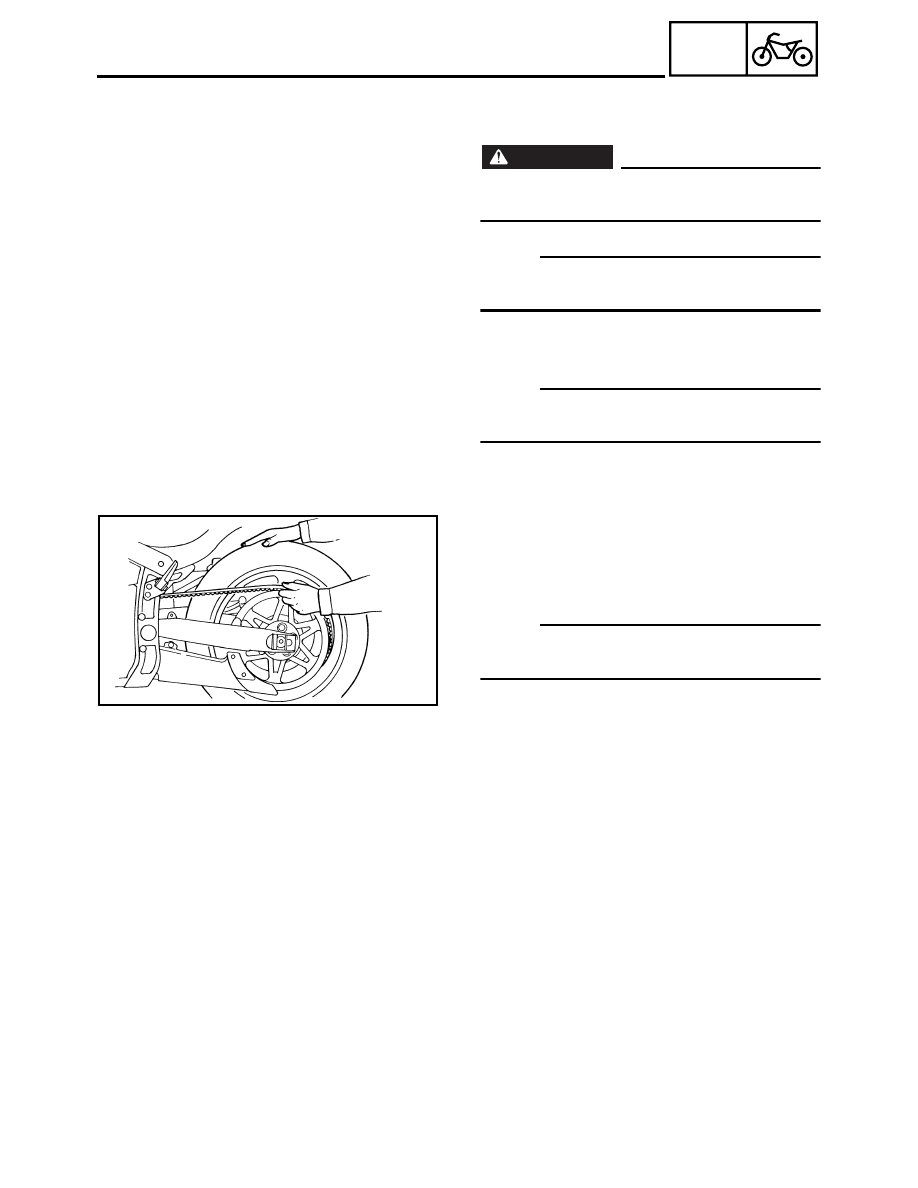
4. Remove:
• wheel axle nut
• wheel axle
• rear wheel
NOTE:
_
Push the rear wheel forward and remove the
drive belt from the rear wheel pulley.
EAS00565
CHECKING THE REAR WHEEL
1. Check:
• wheel axle
• rear wheel
• wheel bearings
• oil seals
Refer to “CHECKING THE FRONT
WHEEL”.
2. Check:
• tire
• rear wheel
Damage/wear
→
Replace.
Refer to “CHECKING THE TIRES” and
“CHECKING THE WHEELS” in chapter 3.
3. Measure:
• radial wheel runout
• lateral wheel runout
Refer to “FRONT WHEEL AND BRAKE
DISCS”.