Yamaha XV1700P, XV1700PC. Service Manual - part 11
3 - 56
CHK
ADJ
CHECKING THE TIRES
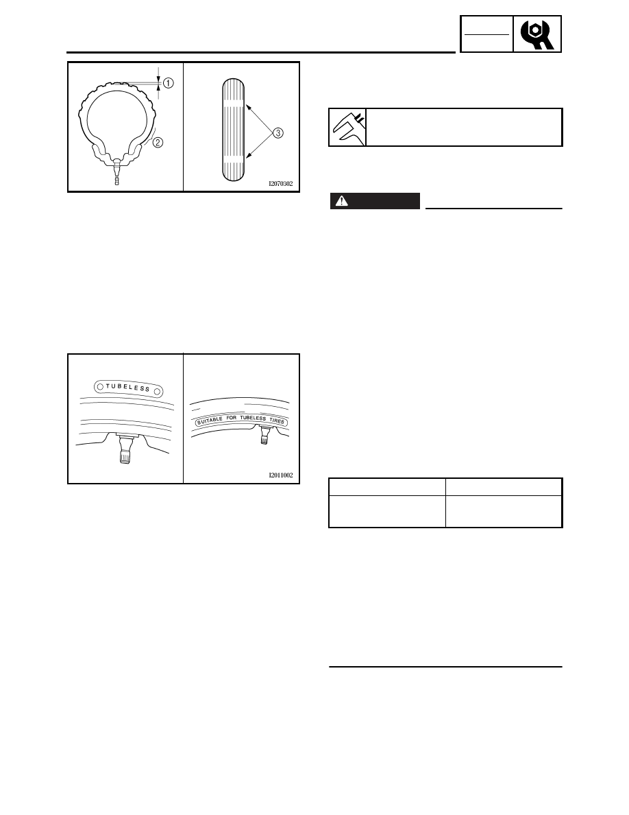
2. Check:
• tire surfaces
Damage/wear
→
Replace the tire.
1
Tire tread depth
2
Sidewall
3
Wear indicator
WARNING
_
• Do not use a tubeless tire on a wheel
designed only for tube tires to avoid tire
failure and personal injury from sudden
deflation.
• When using tube tires, be sure to install
the correct tube.
• Always replace a new tube tire and a new
tube as a set.
• To avoid pinching the tube, make sure the
wheel rim band and tube are centered in
the wheel groove.
• Patching a punctured tube is not recom-
mended. If it is absolutely necessary to
do so, use great care and replace the tube
as soon as possible with a good quality
replacement.
È
Tire
É
Wheel
• After extensive tests, the tires listed
below have been approved by Yamaha
Motor Co., Ltd. for this model. The front
and rear tires should always be by the
same manufacturer and of the same
design. No guarantee concerning han-
dling characteristics can be given if a tire
combination other than one approved by
Yamaha is used on this motorcycle.
Minimum tire tread depth
1.0 mm (0.04 in)
Tube wheel
Tube tire only
Tubeless wheel
Tube or tubeless
tire
È
É