Yamaha XV1700P, XV1700PC. Service Manual - part 12
4 - 1
CHAS
EAS00514
CHASSIS
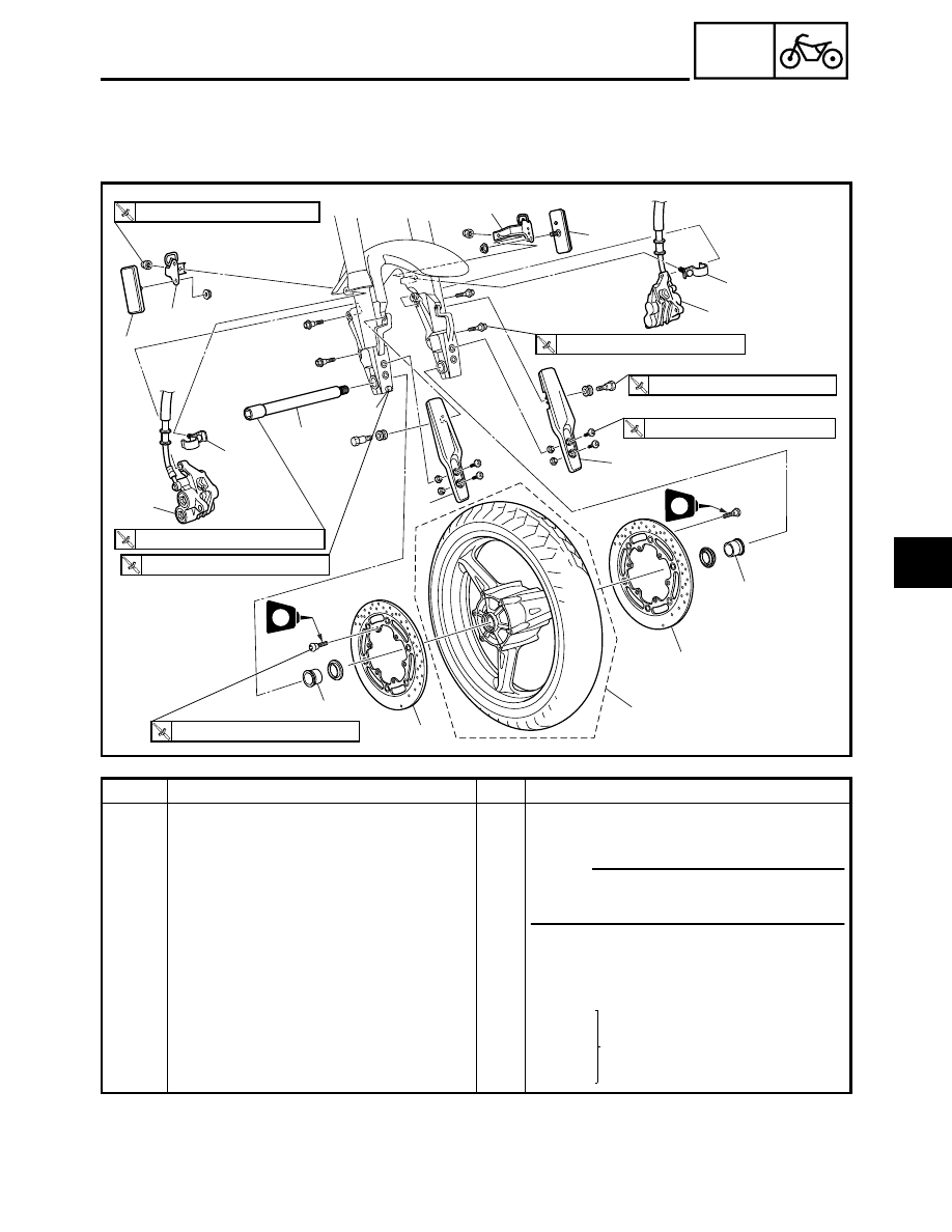
FRONT WHEEL AND BRAKE DISCS
1
3
2
4
5
5
8
10
9
10
8
(6)
7
4
2
1
3
6
(6)
LT
LT
T
R
.
.
18 Nm (1.8 m
•
kg, 13 ft
•
Ib)
T
R
.
.
23 Nm (2.3 m
•
kg, 17 ft
•
Ib)
T
R
.
.
72 Nm (7.2 m
•
kg, 52 ft
•
lb)
T
R
.
.
8 Nm (0.8 m
•
kg, 5.8 ft
•
Ib)
T
R
.
.
16 Nm (1.6 m
•
kg, 11 ft
•
Ib)
T
R
.
.
40 Nm (4.0 m
•
kg, 29 ft
•
Ib)
T
R
.
.
13 Nm (1.3 m
•
kg, 9.4 ft
•
Ib)
Order
Job/Part
Q’ty
Remarks
Removing the front wheel and brake
discs
Remove the parts in the order listed.
NOTE:
_
Place the motorcycle on a suitable stand
so that the front wheel is elevated.
1
Reflector bracket (left and right)
2
2
Brake hose holder
2
3
Reflector (left and right)
2
4
Brake caliper (left and right)
2
Refer to “INSTALLING THE
FRONT WHEEL”.
5
Front fork guard (left and right)
2
6
Wheel axle pinch bolt
1
Loosen.
7
Front wheel axle
1
FRONT WHEEL AND BRAKE DISCS
1
2
3
4