Yamaha XV1700P, XV1700PC. Service Manual - part 14
4 - 33
CHAS
FRONT AND REAR BRAKES
EAS00586
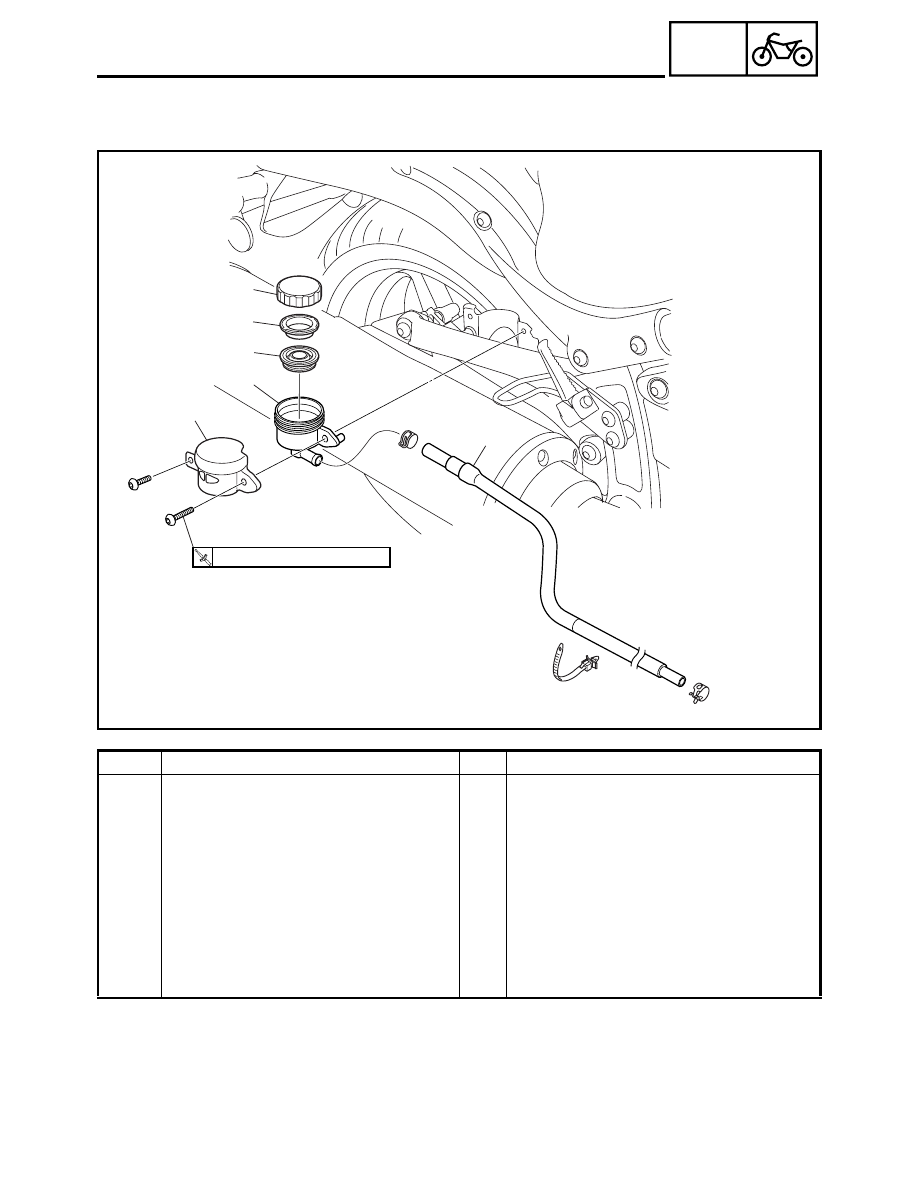
REAR BRAKE MASTER CYLINDER
2
3
4
5
1
6
T
R
.
.
7 Nm (0.7 m
•
kg, 5.1 ft
•
Ib)
Order
Job/Part
Q’ty
Remarks
Removing the brake fluid reservoir
Remove the parts in the order listed.
Brake fluid
Drain.
1
Brake fluid reservoir cover
1
2
Brake fluid reservoir cap
1
3
Brake fluid reservoir diaphragm holder
1
4
Brake fluid reservoir diaphragm
1
5
Brake fluid reservoir
1
6
Brake fluid reservoir hose
1
For installation, reverse the removal
procedure.