ATV Arctic Cat 2001 Line. Service Manual - part 25
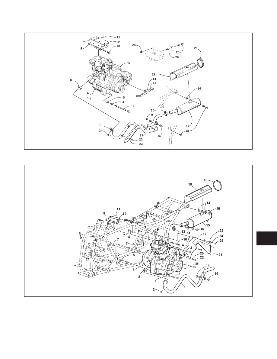
Fig. 8-55
0735-403
Fig. 8-56
0735-527
KEY
1. Exhaust Pipe
2. Cap Screw
3. Cap Screw
4. Washer
5. Spacer
6. Engine
7. Lock Nut
8. Exhaust Seal
9. Nut
10. Cap Screw
11. Cap Screw
12. Engine Bracket
13. Shift Lever
14. Cap Screw
15. Clamp
16. Bushing
17. Muffler
18. Machine Screw
19. Cover
20. Machine Screw
21. Clamp
22. Heat Plate
23. Star Washer
24. Nut
25. Cap Screw
26. Spacer
400/500 cc
(Manual Transmission)
KEY
1. Exhaust Pipe
2. Cap Screw
3. Cap Screw
4. Washer
5. Spacer
6. Engine
7. Lock Nut
8. Exhaust Seal
9. Nut
10. Cap Screw
11. Cap Screw
12. Upper Bracket
13. Clamp
14. Bushing
15. Muffler
16. Machine Screw
17. Cover
18. Clamp
19. Heat Plate
20. Lock Washer
21. Heat Shield
22. Machine Screw
23. Grommet
24. Collar
25. Machine Screw
26. Cap Screw
27. Foam Pad
500 cc
(Automatic Transmission)
8
8-17