ATV Arctic Cat 2001 Line. Service Manual - part 26
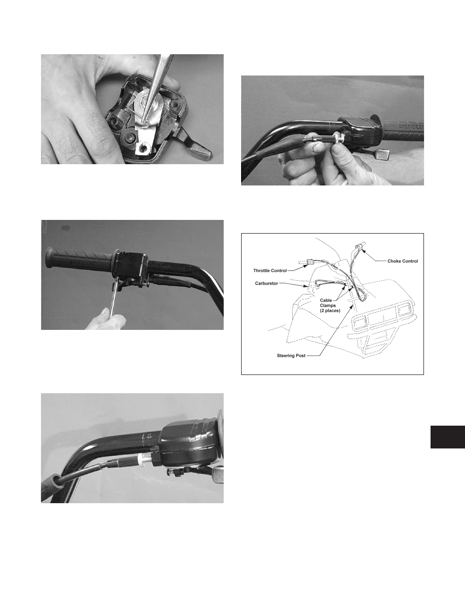
Fig. 9-16
AF680D
3. Place the two halves of the throttle control onto the
handlebars and secure with the two machine
screws.
Fig. 9-17
AL610D
ADJUSTING
1. Slide the boot back to reveal the jam nut; then
loosen the jam nut.
Fig. 9-18
AF682D
2. Rotate the adjuster sleeve until 0.5-1.0 mm
(0.02-0.04 in.) is attained.
Fig. 9-19
AL611D
3. Secure the adjustment by tightening the jam nut;
then slide the boot over the jam nut.
Fig. 9-20
0732-412
9
9-7