ATV Arctic Cat 2001 Line. Service Manual - part 7
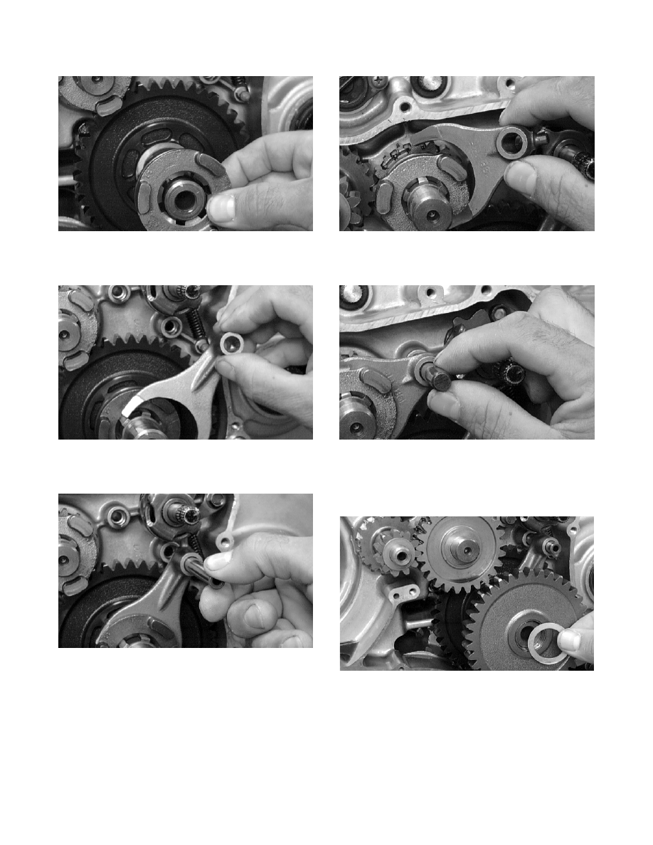
Fig. 3-197
CC466D
8. Install the long shift fork.
Fig. 3-198
CC465D
9. Install the long shift fork shaft.
Fig. 3-199
CC464D
10. Install the short shift fork.
Fig. 3-200
CC463D
11. Install the short shift fork shaft.
Fig. 3-201
CC462D
12. Place the drive gear and washer on the driveshaft.
13. Install the driven gear and washer.
Fig. 3-202
CC460D
14. Install the cam chain; then install the starter clutch
gear assembly.
3-42