ATV Honda TRX350 TM/TE, TRX350 FM/FE. Service Manual - part 58


  Index      Manuals     ATV Honda TRX350 TM/TE, TRX350 FM/FE. Service Manual


Search            copyright infringement  


Content      ..     56      57      58      59     ..


ATV Honda TRX350 TM/TE, TRX350 FM/FE. Service Manual - part 58


±

±

±

±

FLOAT AND JETS

FUEL SYSTEM

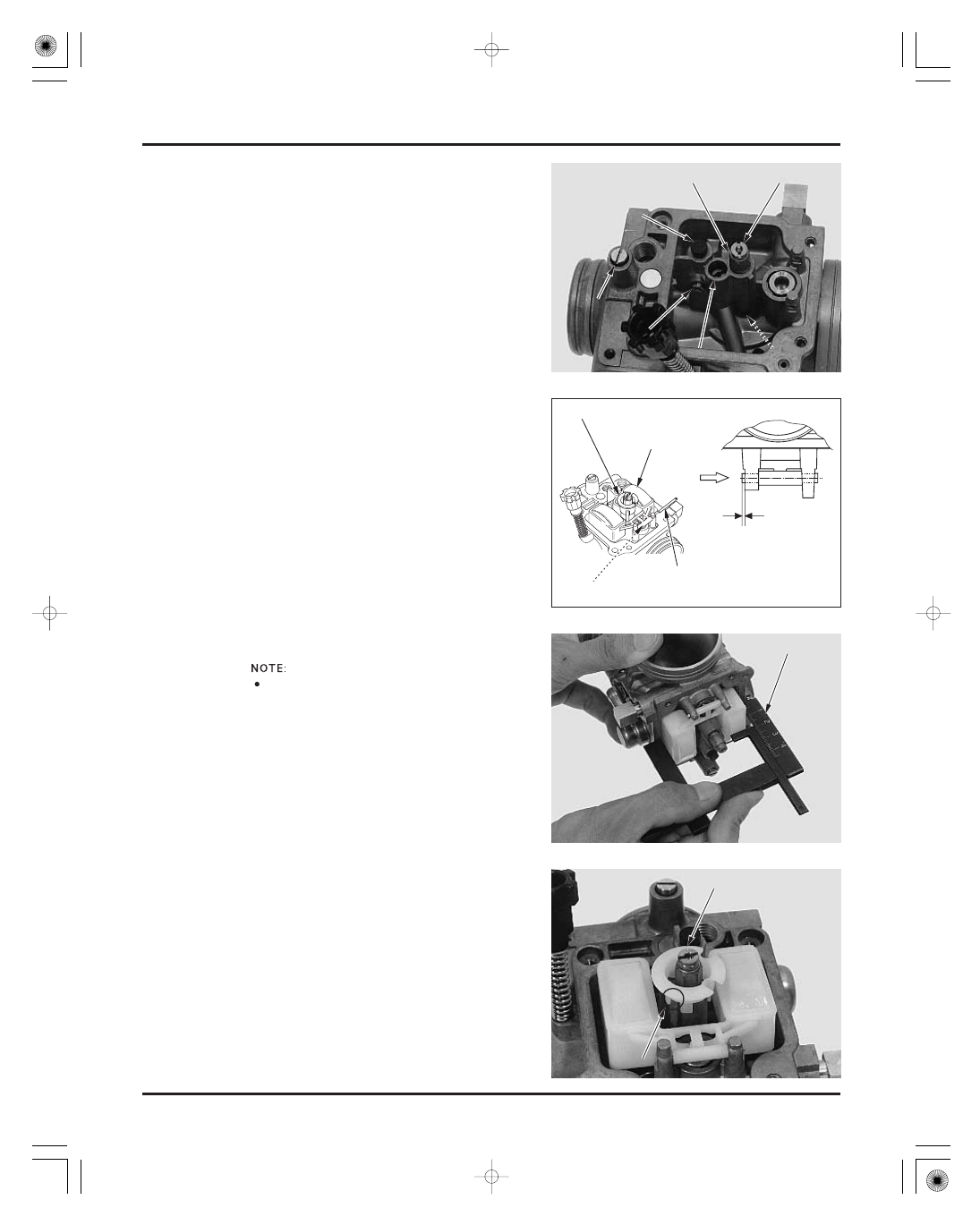
FLOAT LEVEL INSPECTION

TOOL:
Carburetor float level gauge

FLOAT LEVEL:

5-10

needle jet
needle jet holder
main jet
slow jet
starter jet
rubber plug

Check the float level after checking the float valve,
valve seat and float.

With the float valve seated and the float arm just
touching the valve, measure the float level with the
float level gauge.

Install the pilot screw with the spring, washer and a
new O-ring and return it to its original position as
noted during removal.
Perform the pilot screw adjustment if a new pilot
screw is installed.

Install the following:

07401-0010000

18.5 mm (0.73 in)

The float cannot be adjusted.
Replace the float assembly if the float level is out of
specification.

Install the baffle plate by aligning its groove with
the lug on the carburetor body as shown.

Hang the float valve onto the float arm lip.
Install the float valve and float.
Install the float pin as shown.

Install the baffle plate.

R

R

U

U

B

B

B

B

E

E

R

R

P

P

L

L

U

U

G

G

M

M

A

A

I

I

N

N

J

J

E

E

T

T

P

P

I

I

L

L

O

O

T

T

S

S

C

C

R

R

E

E

W

W

S

S

T

T

A

A

R

R

T

T

E

E

R

R

J

J

E

E

T

T

S

S

L

L

O

O

W

W

J

J

E

E

T

T

N

N

E

E

E

E

D

D

L

L

E

E

J

J

E

E

T

T

B

B

A

A

F

F

F

F

L

L

E

E

P

P

L

L

A

A

T

T

E

E

N

N

E

E

E

E

D

D

L

L

E

E

J

J

E

E

T

T

H

H

O

O

L

L

D

D

E

E

R

R

F

F

L

L

O

O

A

A

T

T

L

L

E

E

V

V

E

E

L

L

G

G

A

A

U

U

G

G

E

E

A

A

l

l

i

i

g

g

n

n

B

B

A

A

F

F

F

F

L

L

E

E

P

P

L

L

A

A

T

T

E

E

F

F

L

L

O

O

A

A

T

T

F

F

L

L

O

O

A

A

T

T

V

V

A

A

L

L

V

V

E

E

V

V

I

I

E

E

W

W

F

F

R

R

O

O

M

M

A

A

I

I

R

R

C

C

L

L

E

E

A

A

N

N

E

E

R

R

H

H

O

O

U

U

S

S

I

I

N

N

G

G

S

S

I

I

D

D

E

E

0

0

.

.

5

5

0

0

.

.

3

3

m

m

m

m

(

(

0

0

.

.

0

0

2

2

0

0

.

.

0

0

1

1

i

i

n

n

)

)

P

P

R

R

E

E

S

S

S

S

F

F

I

I

T

T

S

S

I

I

D

D

E

E

F

F

L

L

O

O

A

A

T

T

P

P

I

I

N

N

Damage to the

pilot screw seat

will occur if the

pilot screw is

tightened against

the seat.

Handle the jets

with care. T hey

can easily be

scored or

scratched.

Set the f loat level

gauge so that it is

perpendicular to

the f loat chamber

f ace at the highest

point of the f loat.

T ap the f loat pin

gently with

suitable pin

( O.D. 2 mm)

03/01/08 09:27:13 61HN400C_021

-------------------------------------------------------------------------------------------------------------------------------------------------------------

PRIMER KNOB

VACUUM CHAMBER

FUEL SYSTEM

STANDARD CLIP POSITION:

5-11

Install the primer knob with the spring and tighten
the two screws, being careful not to pinch the
diaphragm.

Install the needle clip onto the jet needle.

Install a new O-ring into the float chamber groove
securely.
Install the float chamber and tighten the four
screws.

Install the washer onto the jet needle and insert the
jet needle into the vacuum piston.

Install the spring into the needle holder and set the
needle holder into the vacuum piston.

Turn the needle holder clockwise while pressing it
until it locks. Holder flange should be fitted the
vacuum piston after turning.

3rd groove from top

O

O

-

-

R

R

I

I

N

N

G

G

S

S

P

P

R

R

I

I

N

N

G

G

P

P

R

R

I

I

M

M

E

E

R

R

K

K

N

N

O

O

B

B

W

W

A

A

S

S

H

H

E

E

R

R

J

J

E

E

T

T

N

N

E

E

E

E

D

D

L

L

E

E

C

C

L

L

I

I

P

P

S

S

P

P

R

R

I

I

N

N

G

G

H

H

O

O

L

L

D

D

E

E

R

R

F

F

L

L

O

O

A

A

T

T

C

C

H

H

A

A

M

M

B

B

E

E

R

R

D

D

I

I

A

A

P

P

H

H

R

R

A

A

G

G

M

M

/

/

P

P

I

I

S

S

T

T

O

O

N

N

03/01/08 09:27:25 61HN400C_022

-------------------------------------------------------------------------------------------------------------------------------------------------------------

AIR CUT-OFF VALVE

FUEL SYSTEM

5-12

Install new O-rings onto the air cut-off valve and
joint pipe.
Install the joint pipe into the air cut-off valve with
the stepped side facing the air cut-off valve.

Install the diaphragm/vacuum piston into the
carburetor body by aligning the tab of the
diaphragm with the air passage, then insert the jet
needle into the needle jet.
Lift the bottom of the piston with your finger to set
the diaphragm rib into the groove in the carburetor
body.

Install the spring and vacuum chamber cover while
the piston remains held in place. Align the concave
of the cover with the air passage in the carburetor
and secure the cover with at least two screws
before releasing the vacuum piston.

Install the screws with the tube clamp and tighten
them.

A

A

l

l

i

i

g

g

n

n

C

C

O

O

V

V

E

E

R

R

S

S

P

P

R

R

I

I

N

N

G

G

C

C

L

L

A

A

M

M

P

P

O

O

-

-

R

R

I

I

N

N

G

G

S

S

J

J

O

O

I

I

N

N

T

T

P

P

I

I

P

P

E

E

A

A

l

l

i

i

g

g

n

n

A

A

I

I

R

R

C

C

U

U

T

T

-

-

O

O

F

F

F

F

V

V

A

A

L

L

V

V

E

E

Be caref ul not to

damage the jet

needle.

Be caref ul not to

pinch the

diaphragm under

the chamber cover,

and to keep the

spring straight

when compressing

the spring.

03/01/08 09:27:34 61HN400C_023

-------------------------------------------------------------------------------------------------------------------------------------------------------------


FUEL SYSTEM

5-13

air cut-off valve vacuum tube
air vent tubes
drain tube

Install the air cut-off valve and secure it with the
screw.

Turn the throttle stop screw to align the butterfly
throttle valve with the edge of the outside by-pass
hole in the carburetor body, If the throttle stop
screw was removed.

Install the collar and carburetor heater with the
stepped side of the collar facing the carburetor and
tighten it.

Install the following tubes to the carburetor and
secure the air vent tube with the clamp as shown:

S

S

C

C

R

R

E

E

W

W

V

V

A

A

C

C

U

U

U

U

M

M

T

T

U

U

B

B

E

E

T

T

H

H

R

R

O

O

T

T

T

T

L

L

E

E

S

S

T

T

O

O

P

P

S

S

C

C

R

R

E

E

W

W

A

A

l

l

i

i

g

g

n

n

C

C

A

A

R

R

B

B

U

U

R

R

E

E

T

T

O

O

R

R

H

H

E

E

A

A

T

T

E

E

R

R

C

C

O

O

L

L

L

L

A

A

R

R

A

A

I

I

R

R

V

V

E

E

N

N

T

T

T

T

U

U

B

B

E

E

S

S

D

D

R

R

A

A

I

I

N

N

T

T

U

U

B

B

E

E

03/01/08 09:27:42 61HN400C_024

-------------------------------------------------------------------------------------------------------------------------------------------------------------


FUEL SYSTEM

5-14

CARBURETOR INSTALLATION

TORQUE:

Perform the following inspections and adjustments.

Connect the throttle cable to the throttle drum and
install the cable adjuster into the carburetor body.

Connect the choke cable by screwing the SE valve
nut, being careful not to damage the SE valve.

Install the carburetor into the insulator by aligning
the lug with the groove, and tighten the band screw.

Tighten the SE valve nut.

Connect the fuel tube.

Install the throttle drum cover by aligning its tab
with the slit in the carburetor and secure it with the
screw.

Route the tubes and wire properly and connect the
carburetor heater connector (page 1-22).

Remove the following:

air cleaner housing (page 5-3)
side covers (page 2-4)

engine idle speed (page 3-12)
throttle operation (page 3-5)

Adjust the pilot screw if it was replaced (page 5-15)

4 N·m (0.4 kgf·m , 2.9 lbf·ft)

S

S

E

E

V

V

A

A

L

L

V

V

E

E

N

N

U

U

T

T

C

C

A

A

R

R

B

B

U

U

R

R

E

E

T

T

O

O

R

R

F

F

U

U

E

E

L

L

T

T

U

U

B

B

E

E

A

A

l

l

i

i

g

g

n

n

S

S

C

C

R

R

E

E

W

W

C

C

O

O

V

V

E

E

R

R

A

A

l

l

i

i

g

g

n

n

S

S

C

C

R

R

E

E

W

W

T

T

H

H

R

R

O

O

T

T

T

T

L

L

E

E

C

C

A

A

B

B

L

L

E

E

A

A

D

D

J

J

U

U

S

S

T

T

E

E

R

R

S

S

E

E

V

V

A

A

L

L

V

V

E

E

N

N

U

U

T

T

03/01/08 09:27:53 61HN400C_025

-------------------------------------------------------------------------------------------------------------------------------------------------------------

±

IDLE DROP PROCEDURE

FUEL SYSTEM

TOOL:
Pilot screw wrench

INTIAL OPENING:

IDLE SPEED:

FINAL OPENING:

5-15

PILOT SCREW ADJUSTMENT

Warm up the engine to operating temperature.
Stop and go riding for 10 minutes is sufficient.
Stop the engine and connect a tachometer
according to the tachometer manufacturer’s
instructions.
Start the engine and adjust the idle speed with
the throttle stop screw.

Turn the pilot screw in or out slowly to obtain the
highest engine speed.
Lightly open the throttle 2

3 times, then adjust

the idle speed with the throttle stop screw.
Turn the pilot screw in gradually until the engine
speed drops by 100 rpm.
Turn the pilot screw out to the final opening.

1-3/4 turns out

1,400

100 rpm

Readjust the idle speed with the throttle stop
screw.

07908-4730002

The pilot screw is factory pre-set and no
adjustment is necessary unless the pilot screw is
replaced.
Use a tachometer with graduations of 50 rpm or
smaller that will accurately indicate a 50 rpm
change.

Turn the pilot screw clockwise until it seats
lightly, then back it out to the specification given.
This is an initial setting prior to the final pilot
screw adjustment.

1-3/4 turns out

P

P

I

I

L

L

O

O

T

T

S

S

C

C

R

R

E

E

W

W

T

T

H

H

R

R

O

O

T

T

T

T

L

L

E

E

S

S

T

T

O

O

P

P

S

S

C

C

R

R

E

E

W

W

P

P

I

I

L

L

O

O

T

T

S

S

C

C

R

R

E

E

W

W

W

W

R

R

E

E

N

N

C

C

H

H

1.

2.

3.

4.

5.

6.

7.

8.

9.

Damage to the

pilot screw seat

will occur if the

pilot screw is

tightened against

the seat.

03/01/08 09:28:04 61HN400C_026

-------------------------------------------------------------------------------------------------------------------------------------------------------------

STANDARD SETTING:
HIGH ALTITUDE SETTING:

STANDARD MAIN JET:
Pilot screw change for low altitude:

HIGH ALTITUDE PILOT SCREW OPENING:

HIGH ALTITUDE MAIN JET:

FUEL SYSTEM

5-16

HIGH ALTITUDE ADJUSTMENT

The carburetor must be adjusted for high altitude
riding (between 3,000

8,000 ft/1,000

2,500 m).

The high altitude carburetor adjustment is
performed as follows:
Remove the carburetor (page 5-4) and the float
chamber.
Replace the standard main jet with the high altitude
type.

Check that the O-ring on the float chamber is in
good condition and replace it with a new one if
necessary.
Install the float chamber and the carburetor.

Turn-in the pilot screw the specified number of
turns from the initial setting.

Below 5,000 ft (1,500 m)

Between 3,000

8,000

ft (1,000

2,500 m)

3/4 turn in from initial opening

Start the engine and adjust the idle speed at high
altitude to ensure proper high altitude operation.

Sustained operation below 5,000 ft (1,500 m) with
the high altitude settings may cause engine
overheating and engine damage. Install the
standard main jet and screw out the pilot screw the
specified number of turns, when riding below 5,000
ft (1,500 m).

130

3/4 turn out

125

Main jet

Below
5,000 ft (1,500 m)

Between
3,000

8,000 ft

(1,000

2,500 m)

130

Factory preset

M

M

A

A

I

I

N

N

J

J

E

E

T

T

P

P

I

I

L

L

O

O

T

T

S

S

C

C

R

R

E

E

W

W

125

Pilot screw
opening

3/4 turns in

from factory preset

03/01/08 09:28:15 61HN400C_027

-------------------------------------------------------------------------------------------------------------------------------------------------------------


REMOVAL/INSTALLATION

FUEL STRAINER SCREEN CLEANING

FUEL SYSTEM

FUEL TANK

HEAT GUARD

5-17

FUEL TANK

Remove the following:

fuel tank cover (page 2-5)
side covers (page 2-4)

Remove the air vent and breather tubes from the
air intake duct.

Loosen the intake duct band screw.
Remove the trim clip and the intake duct from the
air cleaner housing.

Disconnect the fuel tube.
Remove the following:

screw and fuel valve lever
three mounting bolts
fuel tank

Remove the two trim clips and the three cable clips.
Release the four guide tabs off the frame to remove
the fuel tank heat guard.

Installation is in the reverse order of removal.

Route the tubes properly (page 1-22).

Remove the fuel tank.

Drain the gasoline into an approved fuel container.
Turn fuel valve OFF and remove the two mounting
bolts and collars, and the fuel valve.

T

T

R

R

I

I

M

M

C

C

L

L

I

I

P

P

B

B

A

A

N

N

D

D

S

S

C

C

R

R

E

E

W

W

B

B

O

O

L

L

T

T

S

S

F

F

U

U

E

E

L

L

T

T

A

A

N

N

K

K

F

F

U

U

E

E

L

L

T

T

U

U

B

B

E

E

H

H

E

E

A

A

T

T

G

G

U

U

A

A

R

R

D

D

G

G

U

U

I

I

D

D

E

E

T

T

A

A

B

B

S

S

C

C

A

A

B

B

L

L

E

E

C

C

L

L

I

I

P

P

S

S

SCREW

F

F

U

U

E

E

L

L

V

V

A

A

L

L

V

V

E

E

A

A

I

I

R

R

I

I

N

N

T

T

A

A

K

K

E

E

D

D

U

U

C

C

T

T

T

T

R

R

I

I

M

M

C

C

L

L

I

I

P

P

S

S

B

B

R

R

E

E

A

A

T

T

H

H

E

E

R

R

T

T

U

U

B

B

E

E

S

S

B

B

O

O

L

L

T

T

S

S

A

A

N

N

D

D

C

C

O

O

L

L

L

L

A

A

R

R

S

S

AIR GUIDE PLATE

F

F

U

U

E

E

L

L

V

V

A

A

L

L

V

V

E

E

L

L

E

E

V

V

E

E

R

R

Install the heat

guard under the

air guide plate.

03/01/08 09:28:28 61HN400C_028

-------------------------------------------------------------------------------------------------------------------------------------------------------------

FUEL SYSTEM

5-18

Remove the O-ring.
Clean the strainer screen with non-flammable or
high flash point solvent.

Install a new O-ring onto the fuel valve.
Install the fuel valve into the fuel tank and tighten
the bolts with the collars.

Install the fuel tank.

S

S

T

T

R

R

A

A

I

I

N

N

E

E

R

R

O

O

-

-

R

R

I

I

N

N

G

G

03/01/08 09:28:32 61HN400C_029

-------------------------------------------------------------------------------------------------------------------------------------------------------------

MEMO

03/01/08 09:28:34 61HN400C_030

-------------------------------------------------------------------------------------------------------------------------------------------------------------

6-0

ENGINE REMOVAL/INSTALLATION

54 N·m (5.5 kgf·m , 40 lbf·ft)

54 N·m (5.5 kgf·m , 40 lbf·ft)

32 N·m (3.3 kgf·m , 24 lbf·ft)

03/01/08 09:42:58 61HN400D_001

-------------------------------------------------------------------------------------------------------------------------------------------------------------


SERVICE INFORMATION

6-1

ENGINE REMOVAL

6-2

ENGINE INSTALLATION

6-5

SERVICE INFORMATION

6

GENERAL

SPECIFICATIONS

TORQUE VALUES

ITEM

SPECIFICATIONS

6-1

6. ENGINE REMOVAL/INSTALLATION

Other components without above can be serviced with the engine installed in the frame.

alternator and starter clutch (section 10)
transmission (including shift fork and shift drum) (section 11)
crankshaft and balancer (section 11)

When removing and installing the engine, tape the frame around the engine beforehand for frame protection.
The following components require engine removal for service:

32 N·m (3.3 kgf·m , 24 lbf·ft)

54 N·m (5.5 kgf·m , 40 lbf·ft)

54 N·m (5.5 kgf·m , 40 lbf·ft)

Lower engine hanger nut (left and right)
Upper engine hanger nut (frame side)

bolt (engine side)

Engine dry weight

Engine oil capacity

TM model
TE model
FM model
FE model
After draining
After draining/filter change
After disassembly

2.5

(2.6 US qt , 2.2 Imp qt)

2.0

(2.1 US qt , 1.8 Imp qt)

1.95

(2.06 US qt , 1.72 Imp qt)

45.3 kg (99.9 lbs)

44.9 kg (99.0 lbs)

43.4 kg (95.7 lbs)

43.8 kg (96.6 lbs)

03/01/08 09:43:12 61HN400D_002

-------------------------------------------------------------------------------------------------------------------------------------------------------------


ENGINE REMOVAL/INSTALLATION

6-2

ENGINE REMOVAL

Drain the engine oil (page 3-11).

Remove the following:

front fender (page 2-7)
fuel tank and heat guard (page 5-17)
exhaust system (page 2-10)
carburetor assembly (page 5-4)
brake pedal (page 14-19)

Remove the pinch bolt and the gearshift pedal.

Disconnect the spark plug cap.

Remove the four screws and each engine side
cover.

Slide the rubber cap and remove the terminal nut
to disconnect the starter motor cable.

Remove the terminal bolt to disconnect the ground
cable (s).

Disconnect the following connectors:

thermosensor
speed sensor 3P (U.S.A. TM/FM models

option-

al)
gear position switch 2P (All TM/FM models)
alternator 5P
gear position switch 8P (All TE/FE models)

P

P

L

L

U

U

G

G

C

C

A

A

P

P

S

S

I

I

D

D

E

E

C

C

O

O

V

V

E

E

R

R

S

S

M

M

O

O

T

T

O

O

R

R

C

C

A

A

B

B

L

L

E

E

A

A

L

L

T

T

E

E

R

R

N

N

A

A

T

T

O

O

R

R

T

T

E

E

R

R

M

M

O

O

S

S

E

E

N

N

S

S

O

O

R

R

A

A

L

L

T

T

E

E

R

R

N

N

A

A

T

T

O

O

R

R

P

P

E

E

D

D

A

A

L

L

B

B

O

O

L

L

T

T

G

G

E

E

A

A

R

R

P

P

O

O

S

S

I

I

T

T

I

I

O

O

N

N

S

S

W

W

I

I

T

T

C

C

H

H

8

8

P

P

(

(

T

T

E

E

/

/

F

F

E

E

)

)

N

N

U

U

T

T

G

G

R

R

O

O

U

U

N

N

D

D

C

C

A

A

B

B

L

L

E

E

S

S

R

R

U

U

B

B

B

B

E

E

R

R

C

C

A

A

P

P

B

B

O

O

L

L

T

T

G

G

E

E

A

A

R

R

P

P

O

O

S

S

I

I

T

T

I

I

O

O

N

N

S

S

W

W

I

I

T

T

C

C

H

H

2

2

P

P

(

(

T

T

M

M

/

/

F

F

M

M

)

)

T

T

M

M

/

/

F

F

M

M

m

m

o

o

d

d

e

e

l

l

s

s

:

:

T

T

E

E

/

/

F

F

E

E

m

m

o

o

d

d

e

e

l

l

s

s

s

s

h

h

o

o

w

w

n

n

:

:

S

S

P

P

E

E

E

E

D

D

S

S

E

E

N

N

S

S

O

O

R

R

T M/ F M model

only:

03/01/08 09:43:23 61HN400D_003

-------------------------------------------------------------------------------------------------------------------------------------------------------------


ENGINE REMOVAL/INSTALLATION

6-3

angle sensor 3P
shift control motor 2P

Disconnect each oil cooler hose by removing the
bolt.
Remove the O-rings.

Remove the wire band (early TE/FE model
production only) and release the two wire clips.

Remove the bolt and stay and disconnect the re-
verse selector cable from the selector arm.

Remove the three wire bands from the frame down
tube and release the wire clip on the frame cross
member that secured the angle sensor and shift
control motor wires.
Disconnect the following connectors:

BAND

CLIPS

B

B

O

O

L

L

T

T

C

C

A

A

B

B

L

L

E

E

A

A

N

N

G

G

L

L

E

E

S

S

E

E

N

N

S

S

O

O

R

R

3

3

P

P

H

H

O

O

S

S

E

E

S

S

B

B

O

O

L

L

T

T

S

S

T

T

A

A

Y

Y

B

B

A

A

N

N

D

D

S

S

S

S

H

H

I

I

F

F

T

T

C

C

O

O

N

N

T

T

R

R

O

O

L

L

M

M

O

O

T

T

O

O

R

R

2

2

P

P

Early production of the TE/FE models:

CLIPS

T E/ F E model

only:

03/01/08 09:43:34 61HN400D_004

-------------------------------------------------------------------------------------------------------------------------------------------------------------


ENGINE REMOVAL/INSTALLATION

6-4

Remove the propeller shaft from the engine (FM/FE
only; page 15-8).

Loosen the band screw and remove the boot band.
Remove the joint boot from the engine.

Remove the following:

upper hanger bolts and nut
hanger bracket and mounting rubbers

left and right lower hanger nuts

Support the bottom of the engine securely.

Remove the following:

left and right lower hanger bolts
spacers
mounting rubbers

Move the engine forward and disconnect the out-
put shaft from the universal joint.
Remove the engine out of the frame.

Remove the engine hanger bushings and dust seals.

Check the mounting rubbers, hanger bushings and
dust seals for wear or damage.

B

B

O

O

O

O

T

T

S

S

C

C

R

R

E

E

W

W

M

M

O

O

U

U

N

N

T

T

I

I

N

N

G

G

R

R

U

U

B

B

B

B

E

E

R

R

S

S

N

N

U

U

T

T

A

A

N

N

D

D

B

B

O

O

L

L

T

T

B

B

O

O

L

L

T

T

S

S

M

M

O

O

U

U

N

N

T

T

I

I

N

N

G

G

R

R

U

U

B

B

B

B

E

E

R

R

S

S

B

B

R

R

A

A

C

C

K

K

E

E

T

T

B

B

O

O

L

L

T

T

N

N

U

U

T

T

S

S

P

P

A

A

C

C

E

E

R

R

D

D

U

U

S

S

T

T

S

S

E

E

A

A

L

L

H

H

A

A

N

N

G

G

E

E

R

R

B

B

U

U

S

S

H

H

I

I

N

N

G

G

B

B

A

A

N

N

D

D

H

H

A

A

N

N

G

G

E

E

R

R

B

B

U

U

S

S

H

H

I

I

N

N

G

G

M

M

O

O

U

U

N

N

T

T

I

I

N

N

G

G

R

R

U

U

B

B

B

B

E

E

R

R

F

F

r

r

o

o

n

n

t

t

s

s

i

i

d

d

e

e

03/01/08 09:43:47 61HN400D_005

-------------------------------------------------------------------------------------------------------------------------------------------------------------


ENGINE REMOVAL/INSTALLATION

6-5

ENGINE INSTALLATION

TORQUE:

Upper hanger nut (frame side):

Upper hanger bolt (engine side):

Lower hanger nut:

54 N·m (5.5 kgf·m , 40 lbf·ft)

32 N·m (3.3 kgf·m , 24 lbf·ft)

Install the engine into the frame in the reverse
order of removal.

Install the following:

Perform the following inspections and adjustments.

Install the removed parts from engine removal
procedure (page 6-2 to 6-4).

propeller shaft (page 15-23)
exhaust system (page 2-11)
carburetor assembly (page 5-14)
brake pedal (page 14-19)
fuel tank and heat guard (page 5-17)
front fender (page 2-7)

throttle operation (page 3-5)
brake pedal free play (page 3-16)
reverse selector lever free play (page 3-16)

Install the lower hanger bolts and nuts with the
spacers and mounting rubbers while supporting
the engine.

Install the upper hanger bolts, nuts and upper
hanger bracket with the mounting bolt.

Tighten the bolts and nuts to the specified torque.

54 N·m (5.5 kgf·m , 40 lbf·ft)

Apply molybdenum disulfide grease to the out-
put shaft spline.
Note the installation direction of the hanger bolts,
mounting rubbers (large I.D. side facing in) and
dust seals (lips side facing out) and position of
the spacers and mounting rubbers.

Route the wires, cables and tubes properly (page
1-22).
Replace the oil cooler hose O-rings with new
ones and coat them with engine oil.
When installing the gearshift pedal, set the lower
side of the pedal joint horizontally.

D

D

U

U

S

S

T

T

S

S

E

E

A

A

L

L

S

S

3

3

2

2

N

N

·

·

m

m

(

(

3

3

.

.

3

3

k

k

g

g

f

f

·

·

m

m

,

,

2

2

4

4

l

l

b

b

f

f

·

·

f

f

t

t

)

)

5

5

4

4

N

N

·

·

m

m

(

(

5

5

.

.

5

5

k

k

g

g

f

f

·

·

m

m

,

,

4

4

0

0

l

l

b

b

f

f

·

·

f

f

t

t

)

)

H

H

o

o

r

r

i

i

z

z

o

o

n

n

t

t

a

a

l

l

T M/ F M model

only:

03/01/08 09:44:01 61HN400D_006

-------------------------------------------------------------------------------------------------------------------------------------------------------------


Content      ..     56      57      58      59     ..