ATV Honda TRX350 TM/TE, TRX350 FM/FE. Service Manual - part 57


  Index      Manuals     ATV Honda TRX350 TM/TE, TRX350 FM/FE. Service Manual


Search            copyright infringement  


Content      ..     55      56      57      58     ..


ATV Honda TRX350 TM/TE, TRX350 FM/FE. Service Manual - part 57


REMOVAL

RELIEF VALVE CHECK

LUBRICATION SYSTEM

4-4

OIL PUMP

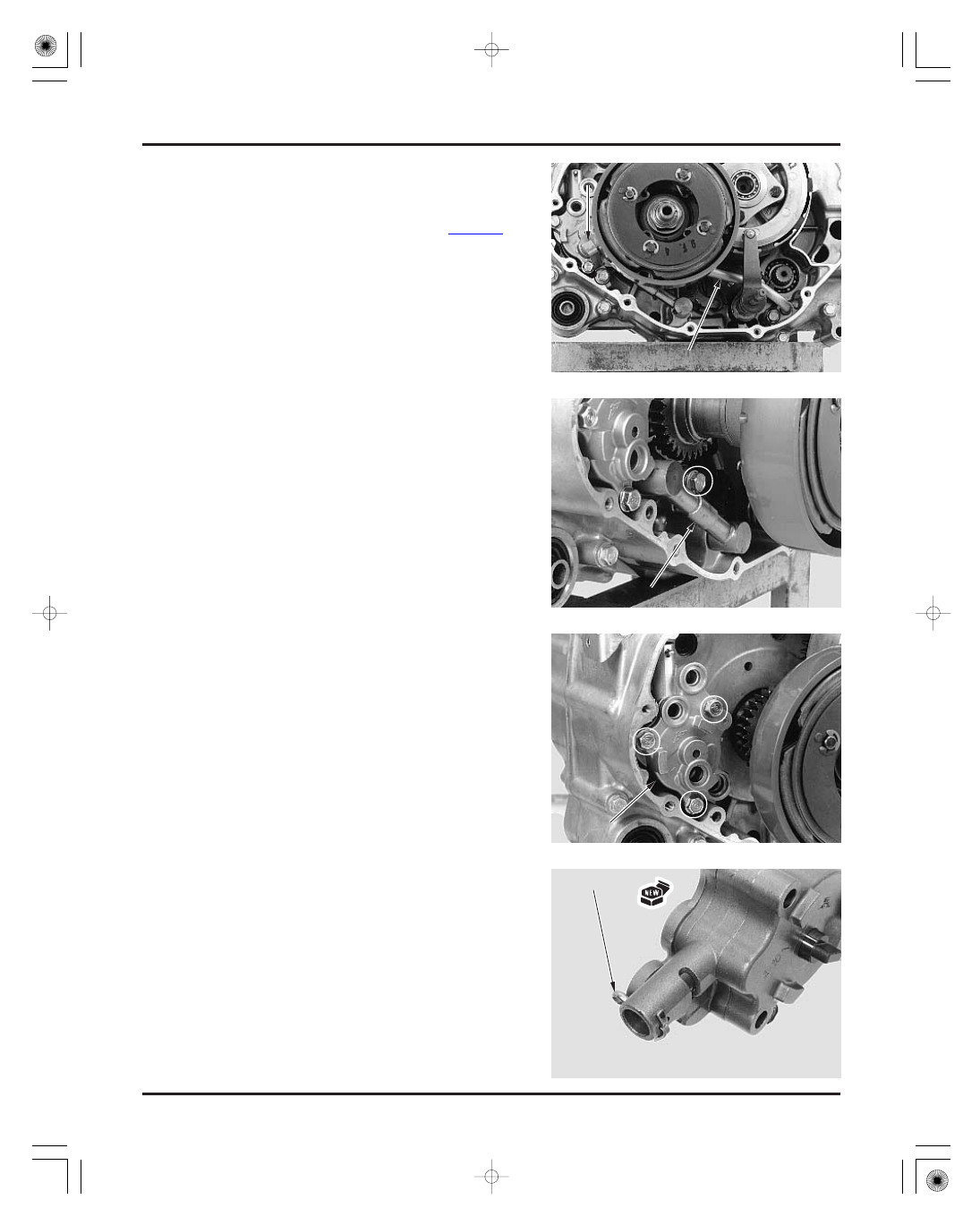
Remove the front crankcase cover (page 9-3).

Remove the following:

Remove the following:

cotter pin
stopper plate
spring
valve

two bolts and retainer
feed oil pipe (long)
O-rings

bolt
scavenge oil pipe (short)
O-rings

three bolts
oil pump

R

R

E

E

T

T

A

A

I

I

N

N

E

E

R

R

O

O

I

I

L

L

P

P

I

I

P

P

E

E

O

O

I

I

L

L

P

P

I

I

P

P

E

E

O

O

I

I

L

L

P

P

U

U

M

M

P

P

C

C

O

O

T

T

T

T

E

E

R

R

P

P

I

I

N

N

03/01/08 09:24:34 61HN400C_005

-------------------------------------------------------------------------------------------------------------------------------------------------------------


DISASSEMBLY

LUBRICATION SYSTEM

4-5

Check the spring and valve for wear or damage.

Install the valve, spring and stopper plate into the
oil pump, then insert a new cotter pin from the
pump body side (outside) and secure it.

Separate the pump body from the pump spacer.
Remove the following:

Remove the bolt and separate the pump base from
the pump spacer.

Remove the following:

inner rotor
outer rotor
drive pin
thrust washer

pump shaft
drive pin
dowel pins
inner rotor
outer rotor

R

R

E

E

L

L

I

I

E

E

F

F

V

V

A

A

L

L

V

V

E

E

S

S

P

P

R

R

I

I

N

N

G

G

S

S

T

T

O

O

P

P

P

P

E

E

R

R

P

P

L

L

A

A

T

T

E

E

P

P

U

U

M

M

P

P

B

B

A

A

S

S

E

E

B

B

O

O

L

L

T

T

P

P

U

U

M

M

P

P

S

S

P

P

A

A

C

C

E

E

R

R

W

W

A

A

S

S

H

H

E

E

R

R

R

R

O

O

T

T

O

O

R

R

S

S

D

D

R

R

I

I

V

V

E

E

P

P

I

I

N

N

R

R

O

O

T

T

O

O

R

R

S

S

D

D

R

R

I

I

V

V

E

E

P

P

I

I

N

N

S

S

H

H

A

A

F

F

T

T

D

D

O

O

W

W

E

E

L

L

P

P

I

I

N

N

S

S

03/01/08 09:24:44 61HN400C_006

-------------------------------------------------------------------------------------------------------------------------------------------------------------

INSPECTION

LUBRICATION SYSTEM

4-6

SERVICE LIMIT:

SERVICE LIMIT:

SERVICE LIMIT:

Measure the pump body clearance.

Measure at several places and use the largest
reading to compare the service limit. If any
portion of the oil pump is worn beyond the
specified service limits, replace the oil pump as
an assembly.

Measure the pump side clearance.

Install the inner and outer rotors into the pump
base and pump body.
Install the pump shaft with the drive pin into the
inner rotor and measure rotor tip clearance.

0.20 mm (0.008 in)

0.25 mm (0.010 in)

0.12 mm (0.005 in)

03/01/08 09:24:54 61HN400C_007

-------------------------------------------------------------------------------------------------------------------------------------------------------------


ASSEMBLY

LUBRICATION SYSTEM

4-7

Install the following into the pump body:

Assemble the pump body and spacer.

Install the following onto the pump shaft and into
the pump base:

thrust washer
drive pin
outer rotor
inner rotor

Assemble the pump body/spacer assembly and
pump base by aligning the drive pin with the
grooves in the inner rotor.

outer rotor
inner rotor
drive pin and shaft with the stepped end facing
pump base (inside)
dowel pins

STOPPER PLATE

P

P

U

U

M

M

P

P

B

B

O

O

D

D

Y

Y

SPRING

RELIEF VALVE

COTTER PIN

DRIVE PIN

PUMP BODY (Feed side)

FEED INNER ROTOR

FEED OUTER ROTOR

PUMP SPACER

THRUST WASHER

SCAVENGE INNER ROTOR

PUMP BASE (Scavenge side)

SCAVENGE OUTER ROTOR

DOWEL PINS

PUMP SHAFT

DRIVE PIN

R

R

O

O

T

T

O

O

R

R

S

S

D

D

O

O

W

W

E

E

L

L

P

P

I

I

N

N

S

S

D

D

R

R

I

I

V

V

E

E

P

P

I

I

N

N

S

S

H

H

A

A

F

F

T

T

P

P

U

U

M

M

P

P

S

S

P

P

A

A

C

C

E

E

R

R

B

B

O

O

D

D

Y

Y

/

/

S

S

P

P

A

A

C

C

E

E

R

R

W

W

A

A

S

S

H

H

E

E

R

R

R

R

O

O

T

T

O

O

R

R

S

S

D

D

R

R

I

I

V

V

E

E

P

P

I

I

N

N

P

P

U

U

M

M

P

P

B

B

A

A

S

S

E

E

03/01/08 09:25:06 61HN400C_008

-------------------------------------------------------------------------------------------------------------------------------------------------------------

INSTALLATION

LUBRICATION SYSTEM

4-8

Be sure that there are no gap between the mating
surfaces and tighten the bolt.

Set the pump assembly onto the crankcase by
aligning the pump shaft end with the balancer
groove and tighten the three bolts securely.

Coat new O-rings with engine oil and install them
onto the scavenge oil pipe.
Install the oil pipe into the crankcase and tighten
the bolt.

Coat new O-rings with engine oil and install them
onto the feed oil pipe.
Install the oil pipe into the crankcase with the two
bolts and retainer.

Install the front crankcase cover (page 9-18).

A

A

l

l

i

i

g

g

n

n

O

O

I

I

L

L

P

P

U

U

M

M

P

P

O

O

I

I

L

L

P

P

I

I

P

P

E

E

O

O

-

-

R

R

I

I

N

N

G

G

S

S

R

R

E

E

T

T

A

A

I

I

N

N

E

E

R

R

O

O

I

I

L

L

P

P

I

I

P

P

E

E

B

B

O

O

L

L

T

T

O

O

-

-

R

R

I

I

N

N

G

G

S

S

03/01/08 09:25:15 61HN400C_009

-------------------------------------------------------------------------------------------------------------------------------------------------------------

MEMO

03/01/08 09:25:18 61HN400C_010

-------------------------------------------------------------------------------------------------------------------------------------------------------------

FUEL SYSTEM

5-0

4 N·m (0.4 kgf·m , 2.9 lbf·ft)

03/01/08 09:25:21 61HN400C_011

-------------------------------------------------------------------------------------------------------------------------------------------------------------

±

SERVICE INFORMATION

5

GENERAL

SPECIFICATIONS

TORQUE VALUES

TOOLS

SERVICE INFORMATION

5-1

TROUBLESHOOTING

5-2

AIR CLEANER HOUSING

5-3

CARBURETOR REMOVAL

5-4

CARBURETOR DISASSEMBLY/
INSPECTION

5-5

CARBURETOR ASSEMBLY

5-9

CARBURETOR INSTALLATION

5-14

PILOT SCREW ADJUSTMENT

5-15

HIGH ALTITUDE ADJUSTMENT

5-16

FUEL TANK

5-17

5-1

5. FUEL SYSTEM

ITEM

SPECIFICATIONS

Carburetor identification number
Main jet
Slow jet
Jet needle clip position
Pilot screw opening
Float level
Idle speed
Throttle lever free play

VE94A

130

42

3rd groove from top

18.5 mm (0.73 in)

1,400

100 rpm

3

8 mm (1/8

5/16 in)

Work in a well ventilated area. Smoking or allowing flames or sparks in the work area or where gasoline is stored can
cause a fire or explosion.
Bending or twisting the control cable will impair smooth operation and could cause the cable to stick or bind, resulting in
loss of vehicle control.
Before removing the carburetor, place an approved fuel container under the drain tube, loosen the drain screw and
drain the carburetor.
After removing the carburetor, cover the intake port of the cylinder head with shop towel to prevent any foreign material
from dropping into the engine.
When disassembling the fuel system parts, note the locations of the O-rings. Replace them with new ones on
reassembly.
If the vehicle is to be stored for more than one month, drain the float chamber. Fuel left in the float chamber may cause
clogged jets, resulting in hard starting or poor driveability.
Refer to section 20 for carburetor heater inspection.

Carburetor insulator band screw

4 N·m (0.4 kgf·m , 2.9 lbf·ft)

Carburetor float level gauge
Pilot screw wrench

07401-0010000
07908-4730002

See page 5-15

03/01/08 09:25:35 61HN400C_012

-------------------------------------------------------------------------------------------------------------------------------------------------------------


TROUBLESHOOTING

Poor performance (driveability) and poor fuel economy

Backfiring or misfiring during acceleration

Afterburn when engine braking is used

Engine stalls, hard to start, rough idling

Engine cranks but won’t start

Lean mixture

Rich mixture

FUEL SYSTEM

5-2

No fuel in tank
No fuel to carburetor

Clogged fuel strainer
Clogged fuel line
Clogged fuel tank breather tube
Misadjusted fuel level

Too much fuel getting to the engine

Clogged air cleaner
Flooded carburetor

Intake air leak
Contaminated/deteriorated fuel

Clogged jets

Clogged starting enrichment valve circuit
Improper starting enrichment valve operation
Improper throttle operation
No spark at plug (faulty ignition system

section 18)

Clogged fuel jets
Faulty float valve
Float level too low
Restricted fuel line
Clogged carburetor air vent tube
Restricted fuel tank breather tube
Intake air leak
Faulty vacuum piston
Faulty throttle valve

Starting enrichment valve open (ON)
Clogged air jets
Faulty float valve
Float level too high
Dirty air cleaner
Worn jet needle or needle jet
Faulty vacuum piston

Restricted fuel line
Fuel mixture too lean/rich
Contaminated/deteriorated fuel

Clogged jets

Intake air leak
Misadjusted idle speed
Misadjusted pilot screw
Misadjusted float level
Restricted fuel tank breather tube
Clogged air cleaner
Clogged slow circuit
Clogged starting enrichment valve circuit
Faulty ignition system (section 18)

Lean mixture
Faulty ignition system (section 18)

Clogged fuel system
Faulty ignition system (section 18)

Lean mixture in slow circuit
Faulty air cut-off valve
Faulty ignition system (section 18)

03/01/08 09:25:52 61HN400C_013

-------------------------------------------------------------------------------------------------------------------------------------------------------------


REMOVAL/INSTALLATION

FUEL SYSTEM

5-3

AIR CLEANER HOUSING

Remove the following:

fuel tank cover (page 2-5)
left side cover (page 2-4)

Remove the air vent and breather tubes from the
air intake duct.

Disconnect the crankcase breather hose.

Loosen the connecting tube band and intake duct
band screws.
Remove the trim clip from the intake duct.

Remove the mounting nut.

Remove the air cleaner housing off the
carburetor and the intake duct from the air
cleaner housing.
Remove the air cleaner housing out of the frame.

Installation is in the reverse order of removal.

Route the tubes properly (page 1-22).

A

A

I

I

R

R

V

V

E

E

N

N

T

T

T

T

U

U

B

B

E

E

INTAKE DUCT

BREATHER TUBES

B

B

R

R

E

E

A

A

T

T

H

H

E

E

R

R

H

H

O

O

S

S

E

E

A

A

I

I

R

R

C

C

L

L

E

E

A

A

N

N

E

E

R

R

H

H

O

O

U

U

S

S

I

I

N

N

G

G

S

S

C

C

R

R

E

E

W

W

S

S

D

D

U

U

C

C

T

T

T

T

R

R

I

I

M

M

C

C

L

L

I

I

P

P

N

N

U

U

T

T

03/01/08 09:26:01 61HN400C_014

-------------------------------------------------------------------------------------------------------------------------------------------------------------


FUEL SYSTEM

5-4

CARBURETOR REMOVAL

Remove the following:

side covers (page 2-4)
air cleaner housing (page 5-3)

Place and approved fuel container under the
drain tube. Loosen the drain screw and drain the
carburetor.

Release the carburetor heater wire from the clip
and disconnect its connector.

Disconnect the fuel tube.
Loosen the starting enrichment (SE) valve nut.

Remove the screw and the throttle drum cover.

Loosen the insulator band screw and remove the
carburetor off the insulator.

Disconnect the choke cable by turning the SE
valve nut, being careful not to damage the SE
valve.

Loosen the throttle cable lock nut and remove the
adjuster from the carburetor body, and
disconnect the cable from the throttle drum.
Remove the carburetor.

T

T

E

E

/

/

F

F

E

E

t

t

y

y

p

p

e

e

s

s

h

h

o

o

w

w

n

n

:

:

H

H

E

E

A

A

T

T

E

E

R

R

W

W

I

I

R

R

E

E

C

C

O

O

N

N

N

N

E

E

C

C

T

T

O

O

R

R

F

F

U

U

E

E

L

L

T

T

U

U

B

B

E

E

S

S

E

E

V

V

A

A

L

L

V

V

E

E

N

N

U

U

T

T

S

S

C

C

R

R

E

E

W

W

C

C

O

O

V

V

E

E

R

R

C

C

A

A

R

R

B

B

U

U

R

R

E

E

T

T

O

O

R

R

S

S

E

E

V

V

A

A

L

L

V

V

E

E

N

N

U

U

T

T

C

C

L

L

I

I

P

P

S

S

C

C

R

R

E

E

W

W

A

A

D

D

J

J

U

U

S

S

T

T

E

E

R

R

T

T

H

H

R

R

O

O

T

T

T

T

L

L

E

E

C

C

A

A

B

B

L

L

E

E

T

T

H

H

R

R

O

O

T

T

T

T

L

L

E

E

D

D

R

R

U

U

M

M

L

L

O

O

C

C

K

K

N

N

U

U

T

T

03/01/08 09:26:10 61HN400C_015

-------------------------------------------------------------------------------------------------------------------------------------------------------------


AIR CUT-OFF VALVE

FUEL SYSTEM

5-5

CARBURETOR DISASSEMBLY/

INSPECTION

air vent tubes
drain tubes
carburetor heater

Remove the attaching screw and the air cut-off
valve.

Remove the O-rings and joint pipe.

Check the SE valve face for scores, scratches or
wear.
Check the SE valve seat at the tip of the valve for
stepped wear.
Check the seal ring for wear or damage.

Remove the following from the carburetor body:

V

V

A

A

L

L

V

V

E

E

S

S

E

E

A

A

T

T

S

S

E

E

A

A

L

L

R

R

I

I

N

N

G

G

T

T

U

U

B

B

E

E

J

J

O

O

I

I

N

N

T

T

P

P

I

I

P

P

E

E

T

T

U

U

B

B

E

E

S

S

A

A

I

I

R

R

C

C

U

U

T

T

-

-

O

O

F

F

F

F

V

V

A

A

L

L

V

V

E

E

S

S

C

C

R

R

E

E

W

W

O

O

-

-

R

R

I

I

N

N

G

G

S

S

C

C

A

A

R

R

B

B

U

U

R

R

E

E

T

T

O

O

R

R

H

H

E

E

A

A

T

T

E

E

R

R

03/01/08 09:26:20 61HN400C_016

-------------------------------------------------------------------------------------------------------------------------------------------------------------

VACUUM CHAMBER

FUEL SYSTEM

5-6

Remove the four screws with the tube clamp and
the vacuum chamber cover while holding it.

Remove the compression spring and diaphragm/
vacuum piston from the carburetor body.

Turn the needle holder counterclockwise by
using a screwdriver while pressing it in and
release the holder flange from the vacuum piston.
Remove the needle holder, spring, jet needle and
washer.

Apply vacuum to the vacuum tube.

The vacuum should be maintained.
Air should not flow through the valve ports when
the vacuum is applied, and should flow when the
vacuum is not applied.

C

C

L

L

A

A

M

M

P

P

S

S

P

P

R

R

I

I

N

N

G

G

N

N

E

E

E

E

D

D

L

L

E

E

H

H

O

O

L

L

D

D

E

E

R

R

V

V

A

A

C

C

U

U

U

U

M

M

T

T

U

U

B

B

E

E

P

P

O

O

R

R

T

T

S

S

V

V

A

A

C

C

U

U

U

U

M

M

C

C

H

H

A

A

M

M

B

B

E

E

R

R

C

C

O

O

V

V

E

E

R

R

D

D

I

I

A

A

P

P

H

H

R

R

A

A

G

G

M

M

/

/

P

P

I

I

S

S

T

T

O

O

N

N

Be caref ul not to

damage the

diaphragm.

03/01/08 09:26:28 61HN400C_017

-------------------------------------------------------------------------------------------------------------------------------------------------------------

PRIMER KNOB

FLOAT CHAMBER

FUEL SYSTEM

5-7

Remove the four screws and the float chamber.

Check the jet needle for stepped wear.
Check the vacuum piston for wear or damage.
Check the diaphragm for pin hole, deterioration
or damage.
Check the vacuum piston for smooth operation
up and down in the carburetor body.

Air will leak out of the vacuum chamber if the
diaphragm is damaged in any way, even with
just a pin hole.

Remove the two screws while holding the primer
knob body.
Remove the primer knob assembly and spring.

Check the diaphragm for pin holes, deterioration
or damage.

J

J

E

E

T

T

N

N

E

E

E

E

D

D

L

L

E

E

D

D

I

I

A

A

P

P

H

H

R

R

A

A

G

G

M

M

/

/

P

P

I

I

S

S

T

T

O

O

N

N

S

S

P

P

R

R

I

I

N

N

G

G

W

W

A

A

S

S

H

H

E

E

R

R

P

P

R

R

I

I

M

M

E

E

R

R

K

K

N

N

O

O

B

B

D

D

I

I

A

A

P

P

H

H

R

R

A

A

G

G

M

M

S

S

P

P

R

R

I

I

N

N

G

G

F

F

L

L

O

O

A

A

T

T

C

C

H

H

A

A

M

M

B

B

E

E

R

R

N

N

E

E

E

E

D

D

L

L

E

E

H

H

O

O

L

L

D

D

E

E

R

R

03/01/08 09:26:37 61HN400C_018

-------------------------------------------------------------------------------------------------------------------------------------------------------------


FUEL SYSTEM

5-8

Remove the following:

baffle plate
float pin
float
float valve

main jet
needle jet holder
needle jet
slow jet
starter jet
rubber plug

Check the float for damage or fuel in the float.

Check the float valve and valve seat for scoring,
scratches, clogging or damage.
Check the tip of the float valve, where it contacts
the valve seat, for stepped wear or contamination.
Check the operation of the float valve.

Remove the following:

Turn the pilot screw in and carefully count the
number of turns until it seats lightly. Make a note of
this to use as a reference when reinstalling the pilot
screw.

Remove the pilot screw, spring, washer and O-ring.

Check each jet for wear or damage.
Check the pilot screw for wear or damage.

Clean the jets with cleaning solvent and blow open
with compressed air.

B

B

A

A

F

F

F

F

L

L

E

E

P

P

L

L

A

A

T

T

E

E

V

V

A

A

L

L

V

V

E

E

S

S

E

E

A

A

T

T

P

P

I

I

L

L

O

O

T

T

S

S

C

C

R

R

E

E

W

W

S

S

L

L

O

O

W

W

J

J

E

E

T

T

O

O

-

-

R

R

I

I

N

N

G

G

W

W

A

A

S

S

H

H

E

E

R

R

S

S

P

P

R

R

I

I

N

N

G

G

N

N

E

E

E

E

D

D

L

L

E

E

J

J

E

E

T

T

P

P

L

L

U

U

G

G

M

M

A

A

I

I

N

N

J

J

E

E

T

T

N

N

E

E

E

E

D

D

L

L

E

E

J

J

E

E

T

T

H

H

O

O

L

L

D

D

E

E

R

R

O

O

-

-

R

R

I

I

N

N

G

G

P

P

I

I

L

L

O

O

T

T

S

S

C

C

R

R

E

E

W

W

F

F

L

L

O

O

A

A

T

T

V

V

A

A

L

L

V

V

E

E

S

S

T

T

A

A

R

R

T

T

E

E

R

R

J

J

E

E

T

T

F

F

L

L

O

O

A

A

T

T

P

P

I

I

N

N

F

F

L

L

O

O

A

A

T

T

V

V

A

A

L

L

V

V

E

E

F

F

L

L

O

O

A

A

T

T

Handle the jets

with care. T hey

can easily be

scored or

scratched.

Damage to the

pilot screw seat

will occur if the

pilot screw is

tightened against

the seat.

T ap the f loat pin

gently with

suitable pin

( O.D. 2 mm)

03/01/08 09:26:48 61HN400C_019

-------------------------------------------------------------------------------------------------------------------------------------------------------------


CARBURETOR CLEANING

FUEL SYSTEM

5-9

CARBURETOR ASSEMBLY

Remove the following:

Blow open all air and fuel passages in the
carburetor body with compressed air.

air cut-off valve
diaphragm/vacuum piston.
main jet, needle jet holder and needle jet
slow jet
starter jet
pilot screw

AIR CUT-OFF VALVE

VACUUM CHAMBER COVER

CLIP

WASHER

CLAMP

JET NEEDLE

PILOT SCREW

BAFFLE PLATE

MAIN JET

SPRING

CARBURETOR HEATER

PRIMER KNOB

JOINT PIPE

PLUG

NEEDLE
JET

COLLAR

NEEDLE
HOLDER

DIAPHRAGM/
VACUUM PISTON

THROTTLE DRUM
COVER

THROTTLE STOP
SCREW

STARTER
JET

NEEDLE JET
HOLDER

COMPRESSION
SPRING

SPRING

DRAIN
SCREW

FLOAT VALVE

FLOAT PIN

FLOAT

FLOAT CHAMBER

SLOW JET

Cleaning the air

and f uel passages

with a piece of

wire will damage

the carburetor

body.

03/01/08 09:26:59 61HN400C_020

-------------------------------------------------------------------------------------------------------------------------------------------------------------


Content      ..     55      56      57      58     ..