ATV Honda TRX350 TM/TE, TRX350 FM/FE. Service Manual - part 55
#
±
LEVEL CHECK
IDLE SPEED:
RECOMMENDED OIL:
TORQUE:
TORQUE:
FINAL GEAR CASE OIL (All models)
MAINTENANCE
3-12
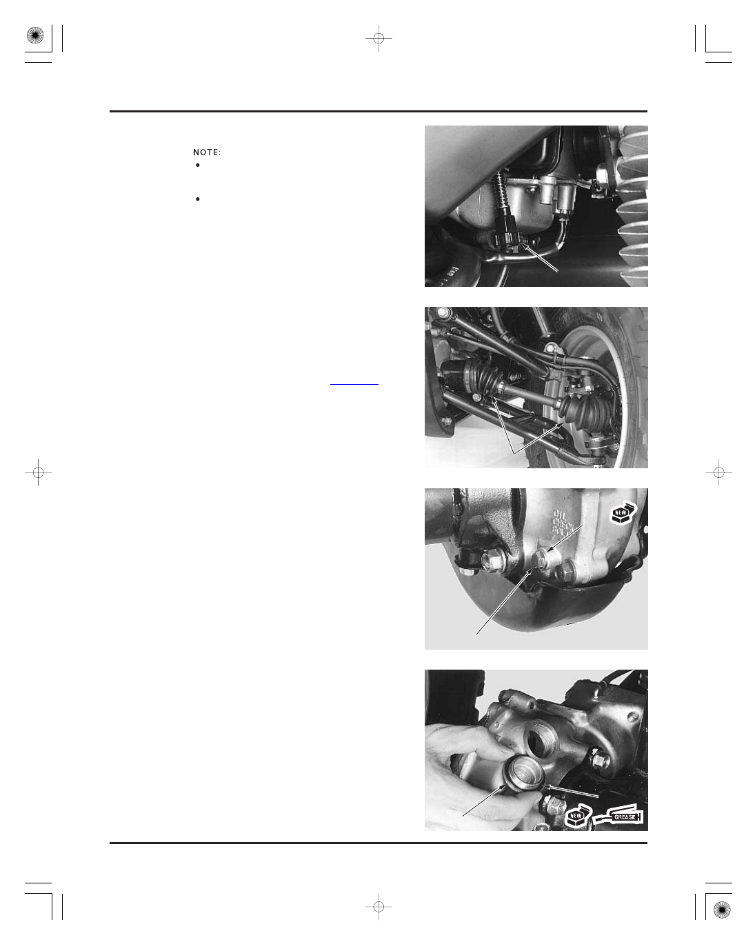
ENGINE IDLE SPEED
REAR FINAL GEAR CASE OIL AND
DIFFERENTIAL OIL
DRIVE SHAFT BOOTS (FM/FE models)
Install the check bolt with a new sealing washer
and tighten it.
12 N·m (1.2 kgf·m , 9 lbf·ft)
12 N·m (1.2 kgf·m , 9 lbf·ft)
Hypoid gear oil SAE
80
Inspect and adjust the idle speed after all other
engine maintenance items have been performed
and are within specifications.
The engine must be warm for accurate
adjustment. Ten minutes of stop-and-go riding is
sufficient.
Warm up the engine, shift the transmission into
neutral and place the vehicle on a level surface.
Check the idle speed and adjust by turning the
throttle stop screw as required.
1,400
100 rpm
Check the drive shaft boots for cuts or other
damage.
If a boot is damaged, replace it (page 15-3).
Place the vehicle on a level surface.
Remove the oil check bolt and check that the oil
flows out of the check bolt hole.
Check for leaks if there is no oil flow.
Remove the oil filler cap and pour the oil slowly
through the filler hole until oil starts to flow out of
the check bolt hole.
Coat a new O-ring with grease and install it into the
filler cap groove.
Install the filler cap and tighten it.
T
T
H
H
R
R
O
O
T
T
T
T
L
L
E
E
S
S
T
T
O
O
P
P
S
S
C
C
R
R
E
E
W
W
C
C
H
H
E
E
C
C
K
K
B
B
O
O
L
L
T
T
F
F
I
I
L
L
L
L
E
E
R
R
C
C
A
A
P
P
O
O
-
-
R
R
I
I
N
N
G
G
B
B
O
O
O
O
T
T
S
S
W
W
A
A
S
S
H
H
E
E
R
R
03/01/08 09:20:11 61HN400B_024