ATV Honda TRX350 TM/TE, TRX350 FM/FE. Service Manual - part 53
GENERAL INFORMATION
1-26
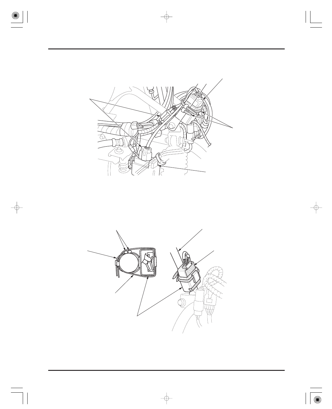
Early production of the TE/FE model only:
SUB-ICM WIRES
CARRY PIPE
Short
Long
SUB-IGNITION CONTROL MODULE
(SUB-ICM)
CONNECTORS
IGNITION CONTROL MODULE (ICM)
PLASTIC BANDS
MOLDING FACE
RUBBER HOUSING
03/01/08 09:12:27 61HN400A_029