ATV Honda TRX350 TM/TE, TRX350 FM/FE. Service Manual - part 56
−
−
−
−
−
−
−
−
−
MAINTENANCE
3-8
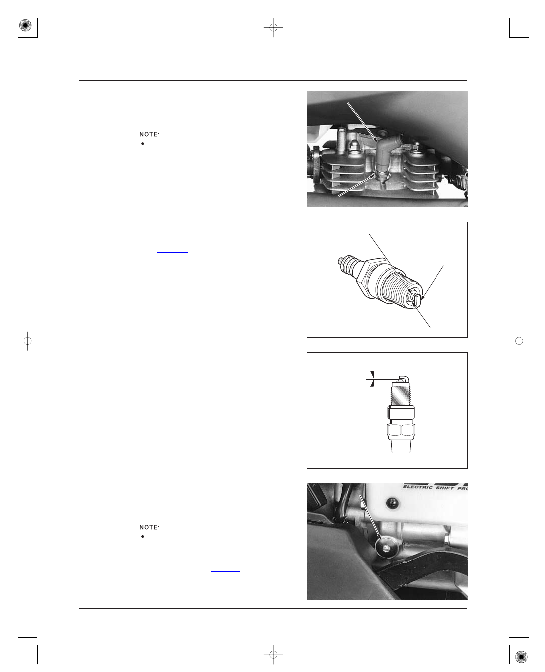
SPARK PLUG
VALVE CLEARANCE
SPARK PLUG GAP:
TORQUE:
Connect the spark plug cap.
Reinstall the spark plug in the cylinder head and
hand-tighten, then torque to specification.
cylinder head cover (page 7-3)
recoil starter cover (page 2-5)
timing hole cap
Remove the following:
18 N·m (1.8 kgf·m , 13 lbf·ft)
0.8
0.9 mm (0.03
0.04 in)
Disconnect the spark plug cap and clean around the
spark plug base.
Clean around the spark plug base with
compressed air before removing the plug, and be
sure that no debris is allowed to enter the
combustion chamber.
Remove the spark plug.
Check the insulator for cracks or damage, and the
electrodes for wear, fouling or discoloration.
Replace the plug if necessary (recommended spark
plug: page 3-1).
Clean the spark plug electrodes with a wire type
brush or special plug cleaner.
Check the gap between the center and side
electrodes with a wire-type feeler gauge. If
necessary, adjust the gap by bending the side
electrode carefully.
Inspect and adjust the valve clearance while the
engine is cold (below 35 °C/95 °F).
P
P
L
L
U
U
G
G
C
C
A
A
P
P
S
S
P
P
A
A
R
R
K
K
P
P
L
L
U
U
G
G
C
C
E
E
N
N
T
T
E
E
R
R
E
E
L
L
E
E
C
C
T
T
R
R
O
O
D
D
E
E
S
S
I
I
D
D
E
E
E
E
L
L
E
E
C
C
T
T
R
R
O
O
D
D
E
E
I
I
N
N
S
S
U
U
L
L
A
A
T
T
O
O
R
R
T
T
I
I
M
M
I
I
N
N
G
G
H
H
O
O
L
L
E
E
C
C
A
A
P
P
0
0
.
.
8
8
0
0
.
.
9
9
m
m
m
m
(
(
0
0
.
.
0
0
3
3
0
0
.
.
0
0
4
4
i
i
n
n
)
)
T o prevent
damage to the
cylinder head,
hand-tighten the
spark plug bef ore
using a wrench to
tighten to the
specif ied torque.
03/01/08 09:19:20 61HN400B_020