ATV Honda TRX350 TM/TE, TRX350 FM/FE. Service Manual - part 23
+
−
−
−
−
−
○
○
−
−
○
○
SYSTEM INSPECTION
ELECTRIC SHIFT PROGRAM (ESP: TE/FE models)
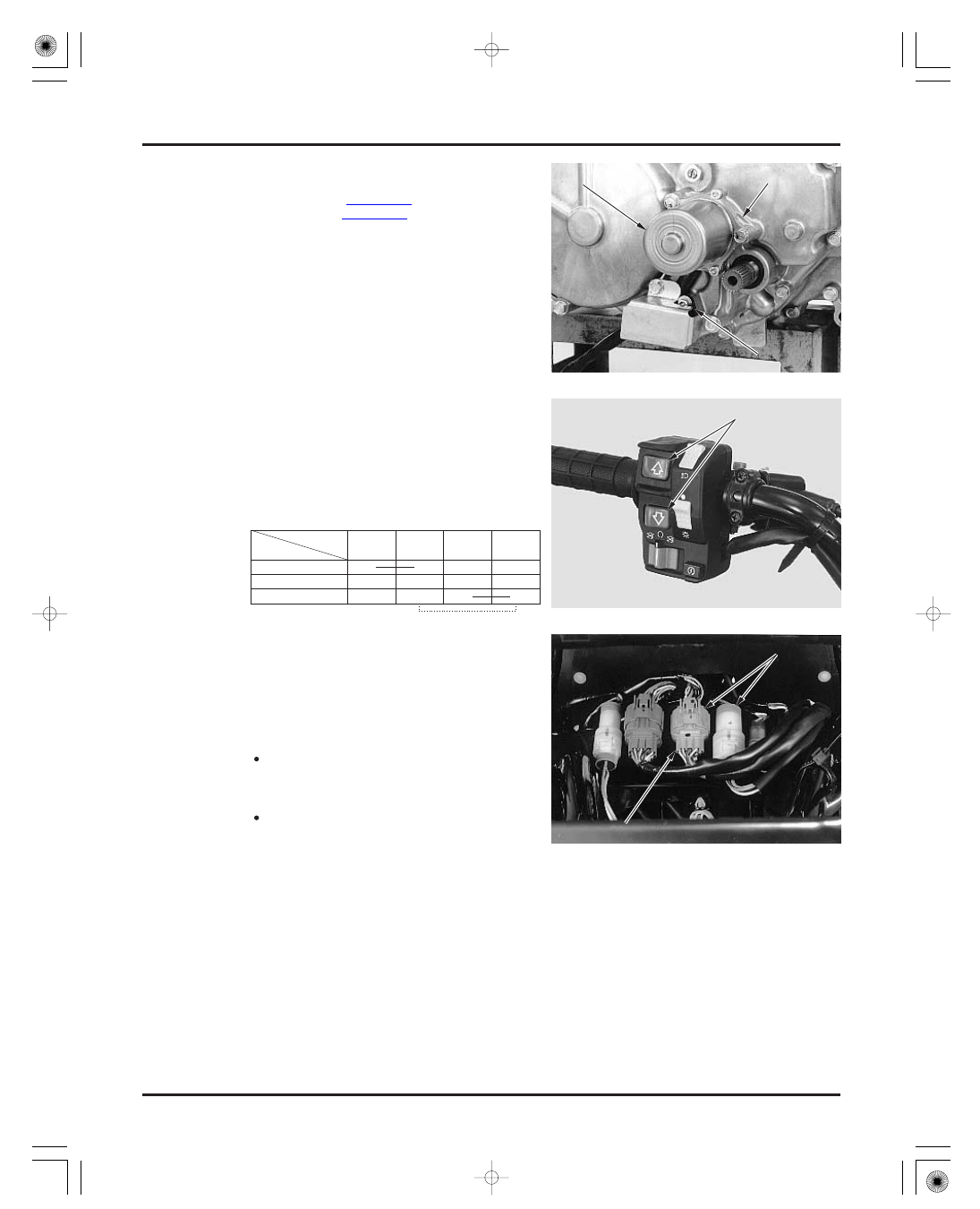
GEARSHIFT SWITCH
STANDARD:
21-24
Install the following:
gear cover
control motor (page 21-23)
angle sensor (page 21-21)
Disconnect the ECU 22P (gray) connector.
Check for continuity between the terminals of the
connector in each switch position.
Continuity should exist between the color coded
wires as follows:
If the continuity is abnormal, perform the same in-
spection at the handlebar switch 10P (green) con-
nector.
Remove the following connectors from the frame
and disconnect the 10P connector:
Connect the control unit 22P connector.
Measure the input voltage between the Black/red
(
) terminal of the harness side 10P (green) connec-
tor and ground (
) with the ignition switch turned
to ‘‘ON’’.
If the continuity at the control unit is abnormal
and the one at the 10P connector is normal, check
for an open or short circuit, or loose or poor con-
nector contact.
If both continuities are abnormal, replace the
gearshift switch.
ignition switch (4P white)
handlebar switch (10P green)
If the input voltage is abnormal, or if there is no
input voltage, check for an open or short circuit in
the wire harness, or loose or poor connections in
the wire harness.
4.7
5.3 V
Color
Position
Up
Free
Down
Black/
red
White/
Yellow
M
M
O
O
T
T
O
O
R
R
G
G
E
E
A
A
R
R
C
C
O
O
V
V
E
E
R
R
G
G
E
E
A
A
R
R
S
S
H
H
I
I
F
F
T
T
S
S
W
W
I
I
T
T
C
C
H
H
R
R
e
e
m
m
o
o
v
v
e
e
f
f
r
r
o
o
m
m
f
f
r
r
a
a
m
m
e
e
1
1
0
0
P
P
C
C
O
O
N
N
N
N
E
E
C
C
T
T
O
O
R
R
A
A
N
N
G
G
L
L
E
E
S
S
E
E
N
N
S
S
O
O
R
R
White/
blue
Black/
red
03/01/08 16:03:26 61HN400N_025