ATV Honda TRX350 TM/TE, TRX350 FM/FE. Service Manual - part 24


  Index      Manuals     ATV Honda TRX350 TM/TE, TRX350 FM/FE. Service Manual


Search            copyright infringement  


Content      ..     22      23      24      25     ..


ATV Honda TRX350 TM/TE, TRX350 FM/FE. Service Manual - part 24


ELECTRIC SHIFT PROGRAM (ESP: TE/FE models)
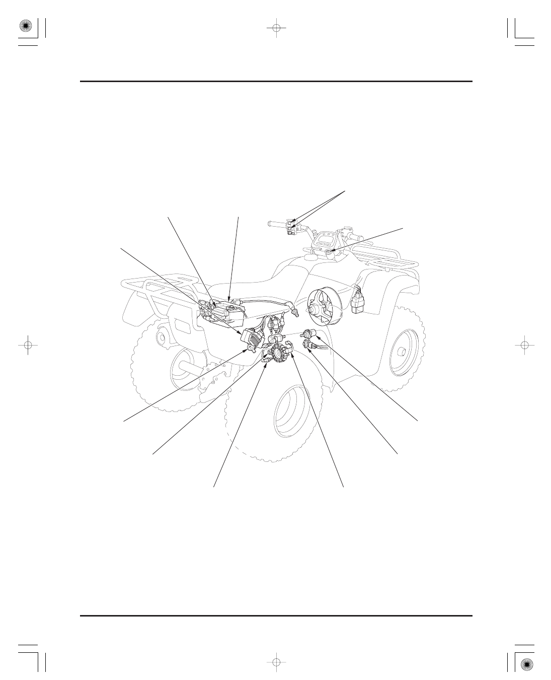
TECHNICAL FEATURES

23-6

Electric Shift Program (ESP) is designed to make gear shift operation easier by replacing conventional foot-operated shift
change with a switch located near the operators hand.

FUSE BOX

SPEED SENSOR

GEAR POSITION SWITCH

REVERSE SHIFT SWITCH

IGNITION PULSE GENERATOR

IGNITION SWITCH

ANGLE SENSOR

BATTERY

ELECTORONIC
CONTOROL UNIT

SHIFT CONTROL
MOTOR

GEARSHIFT SWITCH

03/01/08 16:07:30 61HN400O_014

-------------------------------------------------------------------------------------------------------------------------------------------------------------

COMPONENT DIAGRAM

TECHNICAL FEATURES

Shift Position Indicator

Reverse Shift Switch

Electronic Control Unit

Ignition Pulse Generator

Control Motor

Gearshift Switch

23-7

When the operator presses the gearshift switch installed on the left handlebar, it sends the shift-up or shift-down signal to
Electronic Control Unit.

The reverse shift switch, located on the rear crankcase cover, turns ON when the reverse selector is operated.
The Electronic Control Unit will shift to Reverse and the control motor starts to run.
While the reverse selector is being operated.

The Electronic Control Unit, installed inside the right rear fender, controls the system by processing the signals coming from
each switch and sensor.

The pulse generator, installed inside the rear crankcase cover, controls the ignition system and also sends an engine
revolution signal to the Electronic Control Unit.

The control motor, installed on the front crankcase cover, rotates the sub-gearshift spindle depending on the current from
the Electronic Control Unit.

The shift position indicator incorporated in the combination meter indicates the current shift position, as it receives the signal
from the gear position switch.

COMBINATION
METER

CONTROL MOTOR

IGNITION PULSE GENERATOR

ANGLE SENSOR

TRANSMISSION

SPEED SENSOR

REVERSE
SHIFT
SWITCH

GEAR
POSITION
SWITCH

CLUTCH

IGNITION

SWITCH

E

L

E

C

T

R

ONIC

CONT

ROL

UNIT

(E

CU)

GEARSHIFT
SWITCH

SHIFT DRUM

BATTERY

03/01/08 16:07:43 61HN400O_015

-------------------------------------------------------------------------------------------------------------------------------------------------------------

Angle Sensor

Gear Position Switch

Speed Sensor

Electronic Control Unit

Angle Sensor

DESCRIPTION OF MAJOR COMPONENTS

TECHNICAL FEATURES

23-8

The angle sensor, installed on the front crankcase cover, converts the direction of rotation, rotating angle and rotating speed
of the sub-gearshifts spindle into a voltage change and speed change and outputs them to the Electronic Control Unit.

The gear position switch, installed inside the rear crankcase cover, sends gear position signals to the Electronic Control Unit.

The angle sensor shaft is connected to the end of the sub-gearshift spindle. It converts the direction of rotation, rotating
angle and rotating speed of the sub-gearshift spindle into a voltage change and speed change and then outputs these signals
the Electronic Control Unit.
The rotation of the angle sensor shaft changes a variable resistance value, thereby changing the output voltage to the
Electronic Control Unit from the angle sensor.
The Electronic Control Unit detects whether the gear is shifted down or up during the voltage change.

The speed sensor, installed on the rear crankcase cover, sends a vehicle speed signal both to the combination meter and the
Electronic Control Unit.

Consisting of the CPU and a motor drive circuit, the Electronic Control Unit calculates the signals from each switch and
sensor and controls the ESP system.

The Electronic Control Unit has a self-diagnostic function (though it does not have the capability to display the results) which
checks the system.
If any error is found as the result of self-diagnosis, it shuts off the electric current for operation, bringing ESP to a stop.
If the error is temporary, turn OFF the ignition switch to erase the self-diagnostic results. Then, re-start the engine to
reactivate the system.

REDUCTION GEARS

ANGLE SENSOR

SUB-GEARSHIFT SPINDLE

03/01/08 16:07:53 61HN400O_016

-------------------------------------------------------------------------------------------------------------------------------------------------------------

ENGINE DOES NOT START OR IS
HARD TO START

24-1

ENGINE LACKS POWER

24-2

POOR PERFORMANCE AT LOW AND
IDLE SPEED

24-3

POOR PERFORMANCE AT HIGH SPEED 24-4

POOR HANDLING

24-4

ENGINE DOES NOT START OR IS HARD TO START

24

Possible cause

24-1

24. TROUBLESHOOTING

Not reaching carburetor

Wet plug

Weak or no spark

Engine starts but stops

Low compression

Check fuel flow to carburetor

Reaching carburetor

Remove and inspect spark plug

Good condition

Perform spark test

Good spark

Start by following normal procedure

Engine does not start

Test cylinder compression

Clogged fuel line and strainer
Clogged fuel valve
Clogged fuel tank breather tube

Flooded carburetor
Throttle valve open
Dirty air clearner
Improperly adjusted pilot screw
Starting enrichment (SE) valve stuck
open or damaged

Faulty spark plug
Fouled spark plug
Loose or disconnected ignition
system wires
Broken or shorted spark plug wire
Faulty ignition coil
Faulty ignition pulse generator
Faulty engine stop switch
Faulty ignition switch
Faulty ignition control module (ICM)

Improper choke operation
Incorrectly adjusted carburetor
Leaking carburetor insulator
Improper ignition timing (Faulty ICM
or ignition pulse generator)
Contaminated fuel

Valve clearance too small
Valve stuck open
Worn cylinder and piston rings
Damaged cylinder head gasket
Seized valve
Improper valve timing

1.

2.

3.

4.

5.

03/01/08 16:08:00 61HN400O_017

-------------------------------------------------------------------------------------------------------------------------------------------------------------

ENGINE LACKS POWER

Possible cause

TROUBLESHOOTING

24-2

Raise wheel off the ground and spin
by hand

Wheel spins freely

Check tire pressure

Pressure normal

Check for slipping clutch

Engine speed reduced when clutch
is released

Accelerate lightly

Engine speed increase

Check ignition timing

Correct

Test cylinder compression

Normal compression

Check carburetor for clogging

Not clogged

Remove and inspect spark plugs

Not fouled or discolored

Check oil level and condition

Correct

To following page

Wheel does not spin
freely

Pressure low

Abnormal

Engine speed does not
increase

Incorrect

Low compression

Clogged

Fouled or discolored

Incorrect

Brake dragging
Worn or damaged axle or wheel
bearing

Faulty tire valve
Punctured tire

Clutch slipping
Worn clutch discs/plates
Warped clutch discs/plates
Weak clutch spring
Additive in engine oil

Fuel/air mixture too rich or learn
Clogged air cleaner
Restricted fuel flow
Clogged muffler
Restricted fuel tank breather tube

Faulty ignition control module (ICM)
Faulty ignition pulse generator

Valve clearance too small
Valve stuck open
Worn cylinder and piston rings
Damaged cylinder head gasket
Seized valve
Improper valve timing

Carburetor not serviced frequently
enough

Plug not serviced frequently enough
Incorrect spark plug used

Oil level too high
Oil level too low
Contaminated oil

1.

2.

3.

4.

5.

6.

7.

8.

9.

03/01/08 16:08:06 61HN400O_018

-------------------------------------------------------------------------------------------------------------------------------------------------------------

Possible cause

Possible cause

POOR PERFORMANCE AT LOW AND IDLE SPEED

TROUBLESHOOTING

24-3

See section 5

Loose carburetor insulator bands
Damaged carburetor insulator
Faulty carburetor insulator O-ring

Faulty spark plug
Fouled spark plug
Loose or disconnected ignition system
wires
Broken or shorted spark plug wire
Faulty ignition coil
Faulty ignition pulse generator
Faulty engine stop switch
Faulty ignition switch
Faulty ignition control module (ICM)

Faulty ignition control module (ICM)
Faulty ignition pulse generator

Incorrect

Leaking

Weak or intermittent
spark

Incorrect

Valve train not lubricated
properly

Engine knocks

Clogged oil passage
Clogged oil orifice

Worn piston and cylinder
Use of poor quality fuel
Excessive carbon build-up in
combustion chamber
Ignition timing too advance
(Faulty ICM)
Lean fuel mixture

Check carburetor pilot screw
adjustment

Correct

Check for leaking carburetor
insulator

No leak

Perform spark test

Good spark

Check ignition timing

From previous page

Remove cylinder head cover and
inspect lubrication

Valve train lubricated praperly

Accelerate or run at high speed

Engine does not knock

1.

2.

3.

4.

10.

11.

03/01/08 16:08:14 61HN400O_019

-------------------------------------------------------------------------------------------------------------------------------------------------------------

POOR PERFORMANCE AT HIGH SPEED

POOR HANDLING

Possible cause

Possible cause

TROUBLESHOOTING

24-4

Disconnect fuel tube at carburetor

Fuel flows freely

Check carburetor for clogging

Not clogged

Check valve timing

Correct

Check ignition timing

Correct

Check valve spring

Not weak

Fuel flow restricted

Clogged

Incorrect

Incorrect

Weak

Restricted fuel tube
Restricted fuel tank breather tube
Faulty fuel valve
Clogged fuel strainer

Carburetor not serviced frequently
enough

Camshaft not installed properly

Faulty ignition control module (ICM)
Faulty ignition pulse generator

Faulty valve spring

Steering shaft nut or holder too tight
Damaged steering shaft bushing
Damaged steering shaft bearing

Excessive wheel bearing play
Bent rim
Improperly installed wheel hub
Excessively worn swingarm pivot
bearings
Bent frame

Tire air pressure incorrect
Faulty shock absorber
Bent tie-rod
Incorrect tie-rod adjustment
Bent swingarm
Bent frame
Improper wheel alignment

If steering is heavy

If any wheel is wobbling

If vehicle pulls to one side

1.

2.

3.

4.

5.

1.

2.

3.

03/01/08 16:08:24 61HN400O_020

-------------------------------------------------------------------------------------------------------------------------------------------------------------

25. INDEX

25-1

25

............................................

ACCESSORY SOCKET

. 20-4

..........................................................

AIR CLEANER

. 3-6

........................................

AIR CLEANER HOUSING

. 5-3

.................

AIR CLEANER HOUSING DRAIN HOSE

. 3-7

............................

ALTERNATOR CHARGING COIL

. 17-6

..........................................

ALTERNATOR STATOR

. 10-5

.....................................................

ANGLE SENSOR

. 21-8

A.P. SURETRAC TORQUE BIASING LIMITED SLIP

.....................................................

DIFFERENTIAL

. 23-3

.................................................................

BATTERY

. 17-4

..........................................................

BRAKE FLUID

. 3-14

.....

BRAKE FLUID REPLACEMENT/AIR BLEEDING

. 14-3

...............................................

BRAKE SHOE WEAR

. 3-14

......................................................

BRAKE SYSTEM

. 3-15

.............................................

BULB REPLACEMENT

. 20-2

..............................

CABLE & HARNESS ROUTING

. 1-22

..................................

CAMSHAFT INSTALLATION

. 7-17

...........................................

CAMSHAFT REMOVAL

. 7-15

.....................................

CARBURETOR ASSEMBLY

. 5-9

............................................

CARBURETOR CHOKE

. 3-6

........

CARBURETOR DISASSEMBLY/INSPECTION

. 5-5

..........................................

CARBURETOR HEATER

. 20-8

..............................

CARBURETOR INSTALLATION

. 5-14

.......................................

CARBURETOR REMOVAL

. 5-4

......

CASE BEARING REPLACEMENT (Differential)

. 15-17

.......

CASE BEARING REPLACEMENT (Final drive)

. 16-11

..................

CENTER MUD GUARD (TE/FE models)

. 2-6

.........................................

CENTRIFUGAL CLUTCH

. 9-4

...................................................

CHANGE CLUTCH

. 9-9

........................

CHARGING SYSTEM INSPECTION

. 17-5

...................................................

CLUTCH SYSTEM

. 3-17

COMBINATION METER/SPEED SENSOR (Except

........................................

U.S.A. TM/FM models)

. 20-9

.....

CONTROL MOTOR AND REDUCTION GEARS

. 21-22

.............

COOLING FAN (Except U.S.A. TM model)

. 4-2

.......................................

CRANKCASE ASSEMBLY

. 11-16

...............

CRANKCASE BEARING REPLACEMENT

. 11-12

...................................

CRANKCASE SEPARATION

. 11-3

.....................................

CRANKSHAFT/BALANCER

. 11-10

....................................

CYLINDER COMPRESSION

. 7-3

................................

CYLINDER HEAD ASSEMBLY

. 7-11

...........................

CYLINDER HEAD DISASSEMBLY

. 7-5

..........................

CYLINDER HEAD INSTALLATION

. 7-13

...................................

CYLINDER HEAD REMOVAL

. 7-3

......................

CYLINDER/PISTON INSTALLATION

. 8-5

...............................

CYLINDER/PISTON REMOVAL

. 8-2

....................................

DIFFERENTIAL ASSEMBLY

. 15-19

.......

DIFFERENTIAL DISASSEMBLY/INSPECTION

. 15-9

.............................

DIFFERENTIAL INSTALLATION

. 15-23

......................................

DIFFERENTIAL REMOVAL

. 15-8

......................................................................

DIODE

. 19-10

..................

DRIVE SHAFT BOOTS (FM/FE models)

. 3-12

DRY SUMP MECHANISM OF INTEGRAL OIL

........................................

TANK IN CRANKCASE

. 23-1

ELECTRIC SHIFT PROGRAM

............................................

(ESP: TE/FE models)

. 23-6

EMISSION CONTROL INFORMATION LABEL

.........................................................

(U.S.A. only)

. 1-34

...........................

EMISSION CONTROL SYSTEMS

. 1-33

...............................................

ENGINE IDLE SPEED

. 3-12

.........................................

ENGINE INSTALLATION

. 6-5

.............................................................

ENGINE OIL

. 3-10

................................................

ENGINE OIL FILTER

. 3-11

.................................................

ENGINE REMOVAL

. 6-2

................................................

EXHAUST SYSTEM

. 2-10

.......................................

FINAL DRIVE ASSEMBLY

. 16-13

..........

FINAL DRIVE DISASSEMBLY/INSPECTION

. 16-6

................................

FINAL DRIVE INSTALLATION

. 16-16

.........................................

FINAL DRIVE REMOVAL

. 16-5

..............................

FLYWHEEL/STARTER CLUTCH

. 10-7

..........

FRAME COVER REMOVAL/INSTALLATION

. 2-2

......................

FRONT BRAKE SHOES AND DRUM

. 14-6

................................

FRONT CARRIER/CARRY PIPE

. 2-7

......

FRONT CRANKCASE COVER INSTALLATION

. 9-18

...............

FRONT CRANKCASE COVER REMOVAL

. 9-3

.............................................

FRONT DRIVE SHAFT

. 15-3

......................................................

FRONT FENDER

. 2-7

...................................

FRONT MASTER CYLINDER

. 14-4

..............................................

FRONT MUD GUARD

. 2-6

...................................

FRONT SHOCK ABSORBER

. 12-23

........................................................

FRONT WHEEL

. 12-7

................

FRONT WHEEL CYLINDER AND PANEL

. 14-10

..............................................................

FUEL HOSE

. 3-5

..............................................................

FUEL TANK

. 5-17

.................................................

FUEL TANK COVER

. 2-5

......................................

GEAR POSITION SWITCH

. 20-7

.............................................

GEARSHIFT LINKAGE

. 9-15

.... 9-17

..............................................

GEARSHIFT SWITCH

. 21-24

...........................................................

HANDLEBAR

. 12-3

............................................

HANDLEBAR SWITCH

. 20-5

.............................................................

HEADLIGHT

. 20-3

..................................................

HEADLIGHT GRILL . 2-10

............................

HIGH ALTITUDE ADJUSTMENT

. 5-16

........................................................

IGNITION COIL

. 18-4

..................................................

IGNITION SWITCH

. 20-5

...........................

IGNITION SYSTEM INSPECTION

. 18-3

...................................................

IGNITION TIMING

. 18-5

.......................................................

INNER FENDER

. 2-9

.............................

LUBRICATION & SEAL POINTS

. 1-18

...................................

MAINTENANCE SCHEDULE

. 3-3

.......................................

MODEL IDENTIFICATION

. 1-1

...................................

NUTS, BOLTS, FASTENERS

. 3-18

............................................................

OIL COOLER

. 4-2

..... 20-11

................................................................

OIL PUMP

. 4-4

......................................................

OUTER FENDER

. 2-9

................................

PILOT SCREW ADJUSTMENT

. 5-15

..................................

REAR AXLE INSTALLATION

. 16-17

...........................................

REAR AXLE REMOVAL

. 16-3

...............................................

REAR BRAKE PEDAL

. 14-19

.........................

REAR BRAKE SHOES AND DRUM

. 14-14

........................................................

REAR CARRIER

. 2-8

.........................................................

REAR FENDER

. 2-8

REAR FINAL GEAR CASE OIL AND

..............................................

DIFFERENTIAL OIL

. 3-12

....................

REAR MUD GUARD (TM/FM models)

. 2-5

......................................

REAR SHOCK ABSORBER

. 13-3

...........................................................

REAR WHEEL

. 13-3

....................................................

RECOIL STARTER

. 10-2

.........................................

REGULATOR/RECTIFIER

. 17-6

.......................................

REVERSE LOCK SYSTEM

. 3-16

.......................................

REVERSE SHIFT SWITCH

. 21-25

GEARSHIFT SPINDLE AND REVERSE STOPPER ARM

OIL COOLING SYSTEM/TEMPERATURE INDICATOR

03/01/08 16:08:30 61HN400O_021

-------------------------------------------------------------------------------------------------------------------------------------------------------------

25-2

INDEX

SERVICE INFORMATION

.........................

ALTERNATOR/STARTER CLUTCH

. 10-1

.............................

BATTERY/CHARGING SYSTEM

. 17-1

......................................................

BRAKE SYSTEM

. 14-1

..............................

CLUTCH/GEARSHIFT LINKAGE

. 9-1

CRANKCASE/TRANSMISSION/

......................................................

CRANKSHAFT

. 11-1

.........................................

CYLINDER HEAD/VALVE

. 7-1

.................................................

CYLINDER/PISTON

. 8-1

ELECTRIC SHIFT PROGRAM

............................................

(ESP: TE/FE models)

. 21-1

................................................

ELECTRIC STARTER

. 19-1

......................

ENGINE REMOVAL/INSTALLATION

. 6-1

.........

FRAME/BODY PANELS EXHAUST SYSTEM

. 2-1

...

FRONT DRIVING MECHANISM (FM/FE models)

. 15-1

............

FRONT WHEEL/SUSPENSION/STEERING

. 12-1

.........................................................

FUEL SYSTEM

. 5-1

.................................................

IGNITION SYSTEM

. 18-1

.................................

LIGHTS/METERS/SWITCHES

. 20-1

..........................................

LUBRICATION SYSTEM

. 4-1

.......................................................

MAINTENANCE

. 3-1

.................................

REAR DRIVING MECHANISM

. 16-1

..................................

REAR WHEEL/SUSPENSION

. 13-1

............................................................................

SEAT

. 2-4

..........................................................

SERVICE RULES

. 1-1

................................................................

SIDE COVER

. 2-4

..............................................................

SKID PLATES

. 3-17

......................................................

SPARK ARRESTER

. 3-18

...............................................................

SPARK PLUG

. 3-8

........................................................

SPECIFICATIONS

. 1-3

......................................................

STARTER MOTOR

. 19-4

.........................................

STARTER RELAY SWITCH

. 19-9

..............................

STEERING SHAFT AND TIE-ROD

. 12-19

......................

STEERING SHAFT HOLDER BEARING

. 3-19

...................................................

STEERING SYSTEM

. 3-19

.............................................................

SUSPENSION

. 3-17

....................................................

SUSPENSION ARM

. 12-16

................................................................

SWINGARM

. 13-4

.................................................

THROTTLE HOUSING

. 12-7

.............................................

THROTTLE OPERATION

. 3-5

...........................................................................

TIRES

. 12-8

...................................................................

TOOL BOX

. 2-9

.........................................................................

TOOLS

. 1-16

.......................................................

TORQUE VALUES

. 1-13

.........................................................

TRANSMISSION

. 11-4

TROUBLESHOOTING

.........................

ALTERNATOR/STARTER CLUTCH

. 10-1

.............................

BATTERY/CHARGING SYSTEM

. 17-3

......................................................

BRAKE SYSTEM

. 14-2

..............................

CLUTCH/GEARSHIFT LINKAGE

. 9-2

.....

CRANKCASE/TRANSMISSION/CRANKSHAFT

. 11-2

.........................................

CYLINDER HEAD/VALVE

. 7-2

.................................................

CYLINDER/PISTON

. 8-1

ELECTRIC SHIFT PROGRAM

.............................

(ESP: TE/FE models/’00

’02)

. 21-2

.............................

(ESP: TE/FE models/After ’02)

. 21-8

................................................

ELECTRIC STARTER

. 19-2

ENGINE DOES NOT START OR IS HARD TO

..................................................................

START

. 24-1

.........................................

ENGINE LACKS POWER

. 24-2

.........

FRAME/BODY PANELS EXHAUST SYSTEM

. 2-1

...

FRONT DRIVING MECHANISM (FM/FE models) . 15-2

............

FRONT WHEEL/SUSPENSION/STEERING

. 12-2

.........................................................

FUEL SYSTEM

. 5-2

.................................................

IGNITION SYSTEM

. 18-2

..........................................

LUBRICATION SYSTEM

. 4-1

...................................................

POOR HANDLING

. 24-4

...............

POOR PERFORMANCE AT HIGH SPEED

. 24-4

POOR PERFORMANCE AT LOW AND IDLE

..................................................................

SPEED

. 24-3

.................................

REAR DRIVING MECHANISM . 16-2

...................................

REAR WHEEL/SUSPENSION

. 13-2

...................................................

VALVE CLEARANCE

. 3-8

..................................

VALVE GUIDE REPLACEMENT

. 7-8

......................

VALVE SEAT INSPECTION/REFACING

. 7-8

.....................................

WHEEL HUB AND KNUCKLE

. 12-11

...........................................................

WHEELS/TIRES

. 3-18

.....................................................

WIRING DIAGRAM . 22-0

03/01/08 16:08:35 61HN400O_022

-------------------------------------------------------------------------------------------------------------------------------------------------------------

PARTS CATALOG

TRX350FE’00•’01

FOURTRAX RANCHER 4X4 ES

TRX350FM’00•’01

FOURTRAX RANCHER 4X4

TRX350TE’00•’01

FOURTRAX RANCHER ES

TRX350TM’00•’01

FOURTRAX RANCHER

JANUARY, 2001

AMERICAN HONDA MOTOR CO., INC.

14HN4YE1M (Fiche Version)

2001 AMERICAN HONDA MOTOR CO., INC.,

14HN4YE1P (Paper Version)

(Order through Helm)

-------------------------------------------------------------------------------------------------------------------------------------------------------------

-------------------------------------------------------------------------------------------------------------------------------------------------------------

-------------------------------------------------------------------------------------------------------------------------------------------------------------

HOW TO USE THIS CATALOG

4

2001 American Honda Motor Co., Inc.

JANUARY, 2001

-------------------------------------------------------------------------------------------------------------------------------------------------------------

LOCATION OF SERIAL NUMBER

JANUARY, 2001

2001 American Honda Motor Co., Inc.

5

-------------------------------------------------------------------------------------------------------------------------------------------------------------

SERIAL NUMBERS

6

2001 American Honda Motor Co., Inc.

JANUARY, 2001

Models and applicable serial numbers

Models and applicable serial numbers given in this parts catalog can be identified as follows.

2A = Area Code "A" manufactured at South Carolina factory. Identify by frame serial number.

Engine

Frame

Carburetor

Area

Serial

Serial

Serial

Model

Code

No.

No.

No.

TRX350FE’00

A

TE25E-8000001~

478TE254*YA000001~

VE94A

B

TRX350FM’00

A

TE25E-8000001~

478TE250*YA000001~

VE94A

B

TRX350TE’00

A

TE24E-8000001~

478TE244*YA000001~

VE94A

B

TRX350TM’00

A

TE24E-8000001~

478TE240*YA000001~

VE94A

B

TRX350FE’01

A

TE25E-8000001~

478TE254*1A100001~

VE94A

B

TRX350FE’01

2A TE25E-8000001~

478TE254*14000001~

VE94A

B

TRX350FM’01

A

TE25E-8000001~

478TE250*1A100001~

VE94A

B

TRX350FM’01

2A TE25E-8000001~

478TE250*14000001~

VE94A

B

TRX350TE’01

A

TE24E-8000001~

478TE244*1A100001~

VE94A

B

TRX350TM’01

A

TE24E-8000001~

478TE240*1A100001~

VE94A

B

-------------------------------------------------------------------------------------------------------------------------------------------------------------

CONSTRUCTION OF VEHICLE IDENTIFICATION NUMBER

JANUARY, 2001

2001 American Honda Motor Co., Inc.

7

-------------------------------------------------------------------------------------------------------------------------------------------------------------


Content      ..     22      23      24      25     ..