ATV Honda TRX350 TM/TE, TRX350 FM/FE. Service Manual - part 20


  Index      Manuals     ATV Honda TRX350 TM/TE, TRX350 FM/FE. Service Manual


Search            copyright infringement  


Content      ..     18      19      20      21     ..


ATV Honda TRX350 TM/TE, TRX350 FM/FE. Service Manual - part 20


REMOVAL

DISASSEMBLY/INSPECTION

ELECTRIC STARTER

STARTER MOTOR

19-4

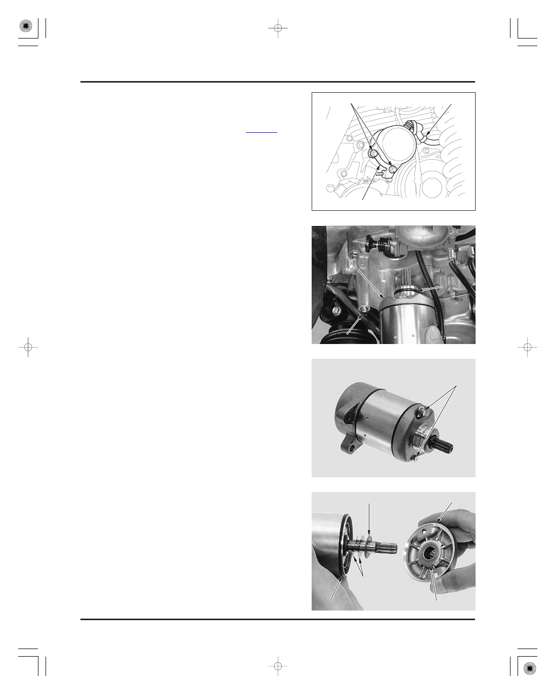
Remove the starter motor case bolts.

Remove the following:

front cover
lock washer
insulated washer
shims
seal ring

Remove the air cleaner housing (page 5-3).

When the ignition switch OFF, remove the negative
cable at the battery before servicing the starter
motor.

Release the rubber cap and remove the terminal
nut to disconnect the starter motor cable.

Remove the two mounting bolts with the air
cleaner housing bracket and the starter motor from
the crankcase cover.

Remove the dowel pin from the crankcase cover.
Remove the O-ring from the starter motor.

O

O

-

-

R

R

I

I

N

N

G

G

S

S

T

T

A

A

R

R

T

T

E

E

R

R

M

M

O

O

T

T

O

O

R

R

B

B

O

O

L

L

T

T

S

S

I

I

N

N

S

S

U

U

L

L

A

A

T

T

E

E

D

D

W

W

A

A

S

S

H

H

E

E

R

R

F

F

R

R

O

O

N

N

T

T

C

C

O

O

V

V

E

E

R

R

L

L

O

O

C

C

K

K

W

W

A

A

S

S

H

H

E

E

R

R

S

S

H

H

I

I

M

M

S

S

S

S

E

E

A

A

L

L

R

R

I

I

N

N

G

G

D

D

O

O

W

W

E

E

L

L

P

P

I

I

N

N

BOLTS

STARTER MOTOR CABLE

BRACKET

Record the

location and

number of shims.

03/01/08 14:13:56 61HN400L_005

-------------------------------------------------------------------------------------------------------------------------------------------------------------


ELECTRIC STARTER

19-5

rear cover
shims
seal ring
armature

Check the bushing in the rear cover for wear or
damage.

Check the dust seal and needle bearing in the front
cover for deterioration, wear or damage.

Check the commutator bars of the armature for
discoloration.

Do not use emery or sand paper on the
commutator.

S

S

H

H

I

I

M

M

S

S

S

S

E

E

A

A

L

L

R

R

I

I

N

N

G

G

R

R

E

E

A

A

R

R

C

C

O

O

V

V

E

E

R

R

A

A

R

R

M

M

A

A

T

T

U

U

R

R

E

E

B

B

U

U

S

S

H

H

I

I

N

N

G

G

D

D

U

U

S

S

T

T

S

S

E

E

A

A

L

L

B

B

E

E

A

A

R

R

I

I

N

N

G

G

C

C

O

O

M

M

M

M

U

U

T

T

A

A

T

T

O

O

R

R

B

B

A

A

R

R

S

S

03/01/08 14:14:04 61HN400L_006

-------------------------------------------------------------------------------------------------------------------------------------------------------------

ELECTRIC STARTER

19-6

Check for continuity between pairs of commutator
bars.
There should be continuity.

Check for continuity between each commutator bar
and the armature shaft.
There should be no continuity.

Check for continuity between the insulated brush
and cable terminal.
There should be continuity.

Check for continuity between the cable terminal
and motor case.
There should be no continuity.

I

I

N

N

S

S

U

U

L

L

A

A

T

T

E

E

D

D

B

B

R

R

U

U

S

S

H

H

03/01/08 14:14:10 61HN400L_007

-------------------------------------------------------------------------------------------------------------------------------------------------------------


ASSEMBLY

ELECTRIC STARTER

19-7

SERVICE LIMIT:

Remove the following:

nut
washer
insulator washers
brush holder assembly
O-ring

9.0 mm (0.35 in)

Remove the brushes from the brush holder.

Measure the brush length.

N

N

U

U

T

T

B

B

R

R

U

U

S

S

H

H

H

H

O

O

L

L

D

D

E

E

R

R

O

O

-

-

R

R

I

I

N

N

G

G

W

W

A

A

S

S

H

H

E

E

R

R

I

I

N

N

S

S

U

U

L

L

A

A

T

T

O

O

R

R

W

W

A

A

S

S

H

H

E

E

R

R

S

S

BRUSH HOLDER

SEAL RING

SEAL RING

REAR COVER

MOTOR CASE

ARMATURE

FRONT COVER

03/01/08 14:14:20 61HN400L_008

-------------------------------------------------------------------------------------------------------------------------------------------------------------


ELECTRIC STARTER

19-8

Install the brushes into the brush holder.

Install the brush holder assembly into the rear
cover by aligning the tab of the holder with the
groove in the rear cover.

Install the following:

new O-ring
insulator washers
washer
nut

Install the armature into the motor case while
holding the armature tightly to keep the magnet of
the case from pulling the armature against it.

Install a new seal ring onto the motor case.
Install the same number of shims in the same
locations as noted during disassembly.

Install the rear cover while pushing in the brushes
into the brush holder by aligning the brush holder
tab with the motor case groove.

Install a new seal ring onto the motor case.
Install the shims and insulated washer onto the
armature shaft.

Apply grease to the dust seal lip and needle
bearing in the front cover.
Install the lock washer onto the front cover and the
front cover over the motor case.

S

S

P

P

R

R

I

I

N

N

G

G

S

S

A

A

l

l

i

i

g

g

n

n

A

A

l

l

i

i

g

g

n

n

S

S

H

H

I

I

M

M

S

S

R

R

E

E

A

A

R

R

C

C

O

O

V

V

E

E

R

R

A

A

R

R

M

M

A

A

T

T

U

U

R

R

E

E

I

I

N

N

S

S

U

U

L

L

A

A

T

T

E

E

D

D

W

W

A

A

S

S

H

H

E

E

R

R

F

F

R

R

O

O

N

N

T

T

C

C

O

O

V

V

E

E

R

R

L

L

O

O

C

C

K

K

W

W

A

A

S

S

H

H

E

E

R

R

S

S

E

E

A

A

L

L

R

R

I

I

N

N

G

G

B

B

R

R

U

U

S

S

H

H

H

H

O

O

L

L

D

D

E

E

R

R

S

S

E

E

A

A

L

L

R

R

I

I

N

N

G

G

S

S

H

H

I

I

M

M

S

S

B

B

R

R

U

U

S

S

H

H

E

E

S

S

T he coil may be

damaged if the

magnet pulls the

armature against

the case.

03/01/08 14:14:30 61HN400L_009

-------------------------------------------------------------------------------------------------------------------------------------------------------------

INSTALLATION

INSPECTION

ELECTRIC STARTER

19-9

STARTER RELAY SWITCH

Remove the maintenance lid (page 17-4).

Shift the transmission into neutral.
Turn the ignition switch ON and push the starter
switch.
The coil is normal if the starter relay switch clicks.

If you don’t hear the switch ‘‘CLICK’’, inspect the
relay switch using the procedure below.

Align the index lines on the front cover and motor
case.
Install the set plates and new O-rings onto the
motor case bolts.
Install the motor case bolts and tighten them.

Coat a new O-ring with engine oil and install it into
the starter motor groove.

Install the dowel pin into the crankcase cover.

Install the starter motor.

Install the mounting bolts with the bracket as
shown and tighten them.

Connect the starter motor cable to the motor
terminal with the terminal nut and tighten it.
Install the rubber cap over the motor terminal
securely.

Install the air cleaner housing (page 5-3).

B

B

O

O

L

L

T

T

A

A

l

l

i

i

g

g

n

n

O

O

-

-

R

R

I

I

N

N

G

G

C

C

A

A

B

B

L

L

E

E

S

S

T

T

A

A

R

R

T

T

E

E

R

R

R

R

E

E

L

L

A

A

Y

Y

S

S

W

W

I

I

T

T

C

C

H

H

S

S

E

E

T

T

P

P

L

L

A

A

T

T

E

E

O

O

-

-

R

R

I

I

N

N

G

G

C

C

A

A

P

P

D

D

O

O

W

W

E

E

L

L

P

P

I

I

N

N

N

N

U

U

T

T

B

B

R

R

A

A

C

C

K

K

E

E

T

T

B

B

O

O

L

L

T

T

S

S

03/01/08 14:14:40 61HN400L_010

-------------------------------------------------------------------------------------------------------------------------------------------------------------

GROUND LINE

STARTER RELAY VOLTAGE

OPERATION CHECK

INSPECTION

ELECTRIC STARTER

DIODE

19-10

Disconnect the starter relay 2P (white) connector.
Check for continuity between the Light green/red
wire terminal of the harness side connector and
ground.

If there is continuity when the transmission is in
neutral, the ground circuit is normal.

Measure the voltage between the Yellow/red wire
terminal (

) of the harness side 2P connector and

ground (

).

If the battery voltage appears only when the starter
switch is pushed with the ignition switch ON, the
circuit is normal.

Remove the maintenance lid (page 17-4).

Remove fuse box cover and the diode.

Disconnect battery (

) cable and starter motor

cable from the starter relay switch.

Connect the fully charged 12 V battery positive
terminal to the Yellow/red wire terminal and
negative terminal to the Green/red wire terminal of
the relay switch side 2P connector.

There should be continuity between the cable
terminals while the battery is connected, and no
continuity when the battery is disconnected.

(

(

)

)

2

2

P

P

C

C

O

O

N

N

N

N

E

E

C

C

T

T

O

O

R

R

D

D

I

I

O

O

D

D

E

E

L

L

i

i

g

g

h

h

t

t

g

g

r

r

e

e

e

e

n

n

/

/

r

r

e

e

d

d

Y

Y

e

e

l

l

l

l

o

o

w

w

/

/

r

r

e

e

d

d

(

(

)

)

2

2

P

P

C

C

O

O

N

N

N

N

E

E

C

C

T

T

O

O

R

R

C

C

A

A

B

B

L

L

E

E

T

T

E

E

R

R

M

M

I

I

N

N

A

A

L

L

S

S

03/01/08 14:14:53 61HN400L_011

-------------------------------------------------------------------------------------------------------------------------------------------------------------

ELECTRIC STARTER

19-11

Check for continuity between the diode terminals.
When there is continuity, a small resistance value
will register.

If there is continuity in one direction, the diode is
normal.

A

C

B

A

C

B

03/01/08 14:14:58 61HN400L_012

-------------------------------------------------------------------------------------------------------------------------------------------------------------

LIGHTS/METERS/SWITCHES

20-0

TE/FE model shown:

HANDLEBAR SWITCH

IGNITION SWITCH

GEAR POSITION SWITCH

OIL THERMOSENSOR

SPEED SENSOR
(U.S.A. TM/FM models-optional)

COOLING FAN MOTOR
(U.S.A. TM model-optional)

COMBINATION METER
(U.S.A. TM/FM models-optional)

03/01/08 15:55:30 61HN400M_001

-------------------------------------------------------------------------------------------------------------------------------------------------------------

×

×

×

×

×

SERVICE INFORMATION

20-1

BULB REPLACEMENT

20-2

HEADLIGHT

20-3

ACCESSORY SOCKET

20-4

IGNITION SWITCH

20-5

HANDLEBAR SWITCH

20-5

GEAR POSITION SWITCH

20-7

CARBURETOR HEATER

20-8

COMBINATION METER/SPEED SENSOR
(Except U.S.A. TM/FM models)

20-9

OIL COOLING SYSTEM/
TEMPERATURE INDICATOR

20-11

SERVICE INFORMATION

20

GENERAL

SPECIFICATIONS

TORQUE VALUES

20. LIGHTS/METERS/SWITCHES

20-1

SPECIFICATIONS

ITEM

All plastic connectors have locking tabs that must be released before disconnecting, and must be aligned when
reconnecting.
A continuity check can usually be made without removing the part from the vehicle. Simply disconnect the connectors
and connect a continuity tester to the terminals or connections.
Check the battery condition before performing any inspection that requires proper battery voltage.
The following color codes used are indicated throughout this section.

Bulbs

Fuse

Sub-fuse

Main fuse

12 V-30/30 W

2

12 V-5 W

30 A

Gear position switch bolt
Oil thermosensor

12 N·m (1.2 kgf·m , 9 lbf·ft)
18 N·m (1.8 kgf·m , 13 lbf·ft)

15 A

2, 10 A

2

12 V-1.7 W

LED

12 V-1.7 W

LED

12 V-1.7 W

LED

LED

12

Headlight (high/low beam)
Taillight
Neutral indicator

Reverse indicator

Oil temperature indicator

Meter light

TM/FM
TE/FE

30 A

Bu: Blue
Bl: Black
Br: Brown

G: Green
Gr: Gray
Lb: Light Blue

R: Red
W: White
Y: Yellow

Lg: Light Green
O: Orange
P: Pink

Apply locking agent to the threads

(Equipped with digital meter)

(Equipped with digital meter)

(No meter)

(No meter)

(Equipped with digital meter)

(Equipped with digital meter)

(No meter)

2

03/01/08 15:55:46 61HN400M_002

-------------------------------------------------------------------------------------------------------------------------------------------------------------

HEADLIGHT

TAILLIGHT

LIGHTS/METERS/SWITCHES

20-2

BULB REPLACEMENT

Open the tool box cover.
Release the taillight wire from the wire guides.

Remove the taillight unit from the box cover by
pushing the mounting studs off the grommets.

Remove the screw and the cover cap by releasing
the tabs from the slits in the headlight cover.

Remove the dust cover from the headlight.

While pushing the bulb socket in, turn it counter-
clockwise to remove it.
Remove the bulb from the headlight and replace it
with a new one.

Install the removed parts in the reverse order of
removal.

Remove the screw and the cover cap by releasing
the tabs from the slits in the headlight cover.

Remove the bulb socket by turning it counterclock-
wise.
Disconnect the bulb connector and replace the bulb
with a new one.

Make sure that the seal rubber on the connector is
installed in position and is in good condition.

Install the bulb in the reverse order of removal.

SCREW

CAP

DUST COVER

SOCKET

BULB

TAB

CAP

BULB

SLIT

CONNECTOR

TAB

WIRE

COVER

STUDS

SCREW

SLIT

Align the socket

tabs with the

headlight grooves

properly.

Align the bulb tab

with the headlight

groove.

Install the dust

cover tightly

against the

headlight with the

‘‘T OP’’ mark

f acing up.

T M/ T E models:

F M/ F E models:

03/01/08 15:55:54 61HN400M_003

-------------------------------------------------------------------------------------------------------------------------------------------------------------


REMOVAL/INSTALLATION

INDICATOR (U.S.A. TM/FM model
only)

LIGHTS/METERS/SWITCHES

20-3

HEADLIGHT

Turn the bulb socket counterclockwise and remove
it.
Pull the bulb out of the socket and replace it with a
new one.

Make sure that the seal rubber is installed in
position and is in good condition.

Install the removed parts in the reverse order of
removal.

Remove the handlebar cover (page 12-3).

Raise the rubber socket toward upper side to
remove it off the cover.
Remove the indicator lens and turn the socket
inside out.
Pull the bulb out of the socket and replace it with a
new one.

Installation is in the reverse order of removal.

aim adjusting bolt and lock washer
mounting bolt
four mounting screws

Remove the headlight assembly from the headlight
grill and the headlight from the cover by releasing
the tabs from the slits.

Installation is in the reverse order of removal.

Adjust the headlight aim (page 20-3).

Remove the headlight bulb (page 20-2).

Remove the following fasteners:

SOCKET

BULB

TAB

HEADLIGHT

WIRE

COVER

WASHER

SCREWS

SLIT

RUBBER SOCKET

ADJUSTING BOLT

MOUNTING BOLT

Route the taillight

wire properly.

Align the socket

lugs with the cover

grooves.

Route the

headlight wire

between the cover

and headlight

properly ( page 1-

22).

03/01/08 15:56:03 61HN400M_004

-------------------------------------------------------------------------------------------------------------------------------------------------------------


HEADLIGHT AIM

INSPECTION

REPLACEMENT

LIGHTS/METERS/SWITCHES

20-4

ACCESSORY SOCKET

Adjust the headlight beam vertically by loosening
the adjusting bolt and moving the headlight back
and forth.
Tighten the mounting bolts.

Disconnect the accessory socket 2P (white)
connector.

Measure the voltage between the White/black (

)

and Green (

) wire terminals of the wire harness

side connector.
There should be battery voltage with the ignition
switch ON.
If there is no voltage, check for open circuit in
related wires.

Remove the accessory socket cap.

Check for continuity between the White/black wire
terminal of the socket side 2P connector and
bottom center terminal of the socket and between
the Green wire terminal and side wall terminal.
There should be continuity.
If there is no continuity, replace the accessory
socket.

Remove the front fender (page 2-7).

Remove the following:

lock nut
inner plate
accessory socket
outer plate

Install a new accessory socket in the reverse order
of removal.

An improperly adjusted headlight may blind
oncoming drivers, or it may fail to light the road
for a safe distance.

C

C

A

A

P

P

LOCK NUT

INNER PLATE

SOCKET CAP

OUTER PLATE

A

A

D

D

J

J

U

U

S

S

T

T

I

I

N

N

G

G

B

B

O

O

L

L

T

T

2

2

P

P

C

C

O

O

N

N

N

N

E

E

C

C

T

T

O

O

R

R

B

B

O

O

T

T

T

T

O

O

M

M

C

C

E

E

N

N

T

T

E

E

R

R

(

(

G

G

r

r

e

e

e

e

n

n

)

)

S

S

I

I

D

D

E

E

W

W

A

A

L

L

L

L

(

(

W

W

h

h

i

i

t

t

e

e

/

/

b

b

l

l

a

a

c

c

k

k

)

)

ACCESSORY SOCKET

Align the socket

lug with the

groove in the f ront

f ender.

03/01/08 15:56:16 61HN400M_005

-------------------------------------------------------------------------------------------------------------------------------------------------------------


INSPECTION

REPLACEMENT

INSPECTION

LIGHTS/METERS/SWITCHES

20-5

IGNITION SWITCH

HANDLEBAR SWITCH

Remove the connectors from the frame in order as
follows:

Disconnect the ignition switch 4P (white) connector.

Check for continuity between the switch side
connector terminals in each switch position.
Continuity should exist between the color coded
wires as follows:

Disconnect the ignition switch connector.
Release the switch wire from the wire clips on the
frame and steering shaft holder.

Remove the handlebar cover or meter cover (page
12-3).
Remove the ignition switch from the cover while
pushing in the two stopper tabs.

Install a new ignition switch by aligning the
locating tab with the groove in the cover.
Connect the ignition switch connector.

Install the handlebar cover or meter cover in the
reverse order of removal.

ignition switch (4P white)
handlebar switch (10P green)

Disconnect the handlebar switch connector (green).

4

4

P

P

C

C

O

O

N

N

N

N

E

E

C

C

T

T

O

O

R

R

I

I

G

G

N

N

I

I

T

T

I

I

O

O

N

N

S

S

W

W

I

I

T

T

C

C

H

H

Align

R

R

e

e

m

m

o

o

v

v

e

e

H

H

A

A

N

N

D

D

L

L

E

E

B

B

A

A

R

R

1

1

0

0

P

P

C

C

O

O

N

N

N

N

E

E

C

C

T

T

O

O

R

R

Red/black

Pink

Red

Black

ON

OFF

Color

Position

TAB

Route the wire

properly ( page 1-

22).

03/01/08 15:56:28 61HN400M_006

-------------------------------------------------------------------------------------------------------------------------------------------------------------

LIGHTS/METERS/SWITCHES

20-6

ENGINE STOP SWITCH

LIGHTING SWITCH

STARTER SWITCH

DIMMER SWITCH

Check for continuity between the switch side
connector terminals in each switch position.
Continuity should exist between the color coded
wires as follows:

BI/G

Color

Position

Position

Position

Color

D

D

I

I

M

M

M

M

E

E

R

R

S

S

T

T

A

A

R

R

T

T

E

E

R

R

E

E

N

N

G

G

I

I

N

N

E

E

S

S

T

T

O

O

P

P

L

L

I

I

G

G

H

H

T

T

I

I

N

N

G

G

D

D

I

I

M

M

M

M

E

E

R

R

S

S

T

T

A

A

R

R

T

T

E

E

R

R

E

E

N

N

G

G

I

I

N

N

E

E

S

S

T

T

O

O

P

P

L

L

I

I

G

G

H

H

T

T

I

I

N

N

G

G

Position

OFF

OFF

OFF

RUN

BI/W

ON

BI/Br

Br

BI/Br

Y/R

FREE

PUSH

Low

(N)

High

W

Bu/Bl

Color

Color

T

T

M

M

/

/

F

F

M

M

m

m

o

o

d

d

e

e

l

l

s

s

:

:

T

T

E

E

/

/

F

F

E

E

m

m

o

o

d

d

e

e

l

l

s

s

:

:

03/01/08 15:56:38 61HN400M_007

-------------------------------------------------------------------------------------------------------------------------------------------------------------

INSPECTION

REPLACEMENT

LIGHTS/METERS/SWITCHES

TM/FM model

TE/FE model

TORQUE:

20-7

GEAR POSITION SWITCH

Remove the right side cover (page 2-4).

Remove the alternator connector, then the gear
position switch connector from the frame.

Disconnect the gear position switch connector.
Check for continuity between each terminal of the
switch side connector and ground.
There should be continuity in each gear position as
follows.

Apply liquid sealant to the grommet outer surface
and install the grommet into the crankcase groove
securely.

Connect the reverse shift switch connector.

Install the rear crankcase cover (page 10-10).

12 N·m (1.2 kgf·m , 9 lbf·ft)

Neutral: Light green/red
Reverse: Gray

Neutral: Light green/red
Reverse: Gray
1st: White/green
2nd: White/red
3rd: Blue
4th: Yellow
5th: Light blue/white

Remove the rear crankcase cover (page 10-7).

Disconnect the reverse shift switch connector.

Remove the wire grommet from the crankcase.
Remove the retaining bolt and the gear position
switch.

Apply locking agent to the retaining bolt threads.
Install a new gear position switch into the
crankcase and tighten the bolt.

G

G

E

E

A

A

R

R

P

P

O

O

S

S

I

I

T

T

I

I

O

O

N

N

S

S

W

W

I

I

T

T

C

C

H

H

B

B

O

O

L

L

T

T

G

G

R

R

O

O

M

M

M

M

E

E

T

T

TM/FM models:

GEAR POSITION SWITCH 2P CONNECTOR

T

T

E

E

/

/

F

F

E

E

m

m

o

o

d

d

e

e

l

l

s

s

:

:

G

G

E

E

A

A

R

R

P

P

O

O

S

S

I

I

T

T

I

I

O

O

N

N

S

S

W

W

I

I

T

T

C

C

H

H

8

8

P

P

C

C

O

O

N

N

N

N

E

E

C

C

T

T

O

O

R

R

A

A

L

L

T

T

E

E

R

R

N

N

A

A

T

T

O

O

R

R

C

C

O

O

N

N

N

N

E

E

C

C

T

T

O

O

R

R

T M/ F M model

only:

T E/ F E model

only:

T E/ F E model

only:

Be caref ul not to

damage the switch
pin and shaf t while

installing.

03/01/08 15:56:52 61HN400M_008

-------------------------------------------------------------------------------------------------------------------------------------------------------------


Content      ..     18      19      20      21     ..