ATV Honda TRX350 TM/TE, TRX350 FM/FE. Service Manual - part 8


  Index      Manuals     ATV Honda TRX350 TM/TE, TRX350 FM/FE. Service Manual


Search            copyright infringement  


Content      ..     6      7      8      9     ..


ATV Honda TRX350 TM/TE, TRX350 FM/FE. Service Manual - part 8


INSPECTION

CYLINDER HEAD/VALVE

TOOL:
Valve guide driver, 5.5 mm

TOOL:
Valve guide reamer, 5.5 mm

7-8

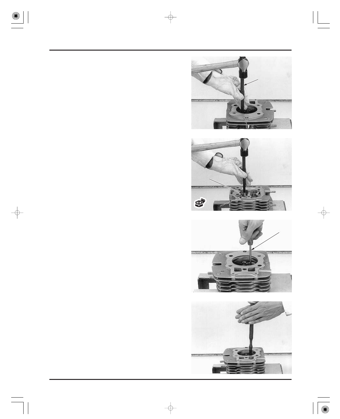
VALVE GUIDE REPLACEMENT

VALVE SEAT INSPECTION/REFACING

Use cutting oil on the reamer during this operation.

Clean the cylinder head thoroughly to remove any
metal particles after reaming and reface the valve
seat (see below).

Clean all intake and exhaust valves thoroughly to
remove carbon deposits.

Apply a light coating of Prussian Blue to each valve
seat.
Tap the valve against the valve seat several times
without rotating the valve, to check for proper valve
seat contact.

Install new O-rings onto the new valve guides.
Drive the new valve guides in the cylinder head
from the rocker arm side using the same tool while
the cylinder head is still heated.

Let the cylinder head cool to room temperature.

Ream the new valve guides.
Insert the reamer from the combustion chamber
side of the head and always rotate the reamer
clockwise.

07984-2000001 or
07984-200000D
(U.S.A. only)

Chill new valve guides in the freezer section of a
refrigerator for about an hour.
Heat the cylinder head to 130

140°C (275

290°F)

with a hot plate or oven. Do not heat the cylinder
head beyond 150°C (300°F). Use temperature
indicator sticks, available from welding supply
stores, to be sure the cylinder head is heated to the
proper temperature.

Support the cylinder head and drive the valve
guides out of the cylinder head from the
combustion chamber side.

07742-0010100

O

O

-

-

R

R

I

I

N

N

G

G

V

V

A

A

L

L

V

V

E

E

G

G

U

U

I

I

D

D

E

E

D

D

R

R

I

I

V

V

E

E

R

R

V

V

A

A

L

L

V

V

E

E

G

G

U

U

I

I

D

D

E

E

R

R

E

E

A

A

M

M

E

E

R

R

T ake care not to

tilt or lean the

reamer in the

guide while

reaming.

Be sure to wear
heavy gloves to

avoid burns when

handling the

heated cylinder

head.

Using a torch to

heat the cylinder

head may cause

warpage.

03/01/08 09:46:00 61HN400D_015

-------------------------------------------------------------------------------------------------------------------------------------------------------------

REFACING

CYLINDER HEAD/VALVE

7-9

STANDARD:
SERVICE LIMIT:

Uneven seat width:

Replace the valve and reface the valve seat.

Damaged face:

Replace the valve and reface the valve seat.

Contact area (too high or too low)

Reface the valve seat.

Follow the refacing manufacturer’s operating
instructions.
Be careful not to grind the seat more than
necessary.

Remove the valve and inspect the valve seat face.
The valve seat contact should be within the speci-
fied width and even all around the circumference.

If the valve seat width is not within specification,
reface the valve seat.

Inspect the valve seat face for:

1.5 mm (0.06 in)

1.2 mm (0.05 in)

SEAT WIDTH

DAMAGED FACE

TOO LOW

45 °

32 °

60 °

TOO HIGH

UNEVEN SEAT
WIDTH

T he valve cannot

be ground. If the

valve f ace is

burned or badly

worn or if it

contacts the seat

unevenly, replace

the valve.

03/01/08 09:46:14 61HN400D_016

-------------------------------------------------------------------------------------------------------------------------------------------------------------

TOOLS:
Flat cutter, 38.5 mm (IN)
Flat cutter, 33 mm (EX)
Cutter holder, 5.5 mm

TOOLS:
Interior cutter, 37.5 mm (IN)
Interior cutter, 30 mm (EX)
Cutter holder, 5.5 mm

TOOLS:
Valve seat cutter, 35 mm (IN)
Valve seat cutter, 29 mm (EX)
Cutter holder, 5.5 mm

or equivalent commercially available in U.S.A.

or equivalent commercially available in U.S.A.

or equivalent commercially available in U.S.A.

CYLINDER HEAD/VALVE

7-10

07780-0012400
07780-0012900
07781-0010101

07780-0014100
07780-0014000
07781-0010101

If the contact area is too high on the valve, the seat
must be lowered using a 32° flat cutter.

If the contact area is too low on the valve, the seat
must be raised using a 60° interior cutter.

Using a 45° seat cutter, remove any roughness or
irregularities from the seat.

Using a 60° interior cutter, remove 1/4 of the
existing valve seat material.

Using a 32° flat cutter, remove 1/4 of the existing
valve seat material.

07780-0010400
07780-0010300
07781-0010101

ROUGHNESS

CONTACT TOO HIGH

CONTACT TOO LOW

OLD SEAT WIDTH

OLD SEAT WIDTH

OLD SEAT
WIDTH

OLD SEAT
WIDTH

32°

60°

32°

60°

03/01/08 09:46:28 61HN400D_017

-------------------------------------------------------------------------------------------------------------------------------------------------------------

CYLINDER HEAD/VALVE

7-11

VALVE SEAT WIDTH:

After ’02:

CYLINDER HEAD ASSEMBLY

Using a 45° seat cutter, cut the seat to the proper
width.

Make sure that all pitting and irregularities are
removed.

After cutting the seat, apply lapping compound to
the valve face, and lap the valve using light pres-
sure.
Change the angle of lapping tool frequently to pre-
vent uneven seat wear.

After lapping, wash any residual compound off the
cylinder head and valve and recheck the seat
contact.

1.2 mm (0.05 in)

SEAT WIDTH

CYLINDER HEAD

EXHAUST VALVE

O-RING

INNER SPRING

STEM SEAL

SPRING SEAT

VALVE GUIDE

SPRING RETAINER

OUTER SPRING

45°

H

H

A

A

N

N

D

D

-

-

L

L

A

A

P

P

P

P

I

I

N

N

G

G

T

T

O

O

O

O

L

L

SPRING COTTER

INTAKE VALVE

Excessive lapping

pressure may

def orm or damage

the seat.

Do not allow

lapping compound

to enter the guides.

03/01/08 09:46:36 61HN400D_018

-------------------------------------------------------------------------------------------------------------------------------------------------------------

CYLINDER HEAD

CYLINDER HEAD/VALVE

TOOL:
Valve spring compressor

7-12

07757-0010000

Blow through the oil passage (stud bolt hole) in the
cylinder head with compressed air.
Install the valve spring seats.
Install new stem seals.
Lubricate the valve stem sliding surface with molyb-
denum oil solution.
Insert the valve into the guide while turning it
slowly to avoid damage to the stem seal.

Install the inner and outer valve springs with the
tightly wound coils facing the combustion chamber.

Install the spring retainer.

Install the valve spring cotters using the valve
spring compressor.

Support the cylinder head so that the valve heads
will not contact anything that cause damage.
Tap the valve stems gently with two plastic
hammers as shown to seat the cotters firmly.

Install the spark plug.

R

R

E

E

T

T

A

A

I

I

N

N

E

E

R

R

S

S

P

P

R

R

I

I

N

N

G

G

S

S

E

E

A

A

T

T

S

S

P

P

R

R

I

I

N

N

G

G

C

C

O

O

M

M

P

P

R

R

E

E

S

S

S

S

O

O

R

R

C

C

O

O

T

T

T

T

E

E

R

R

S

S

V

V

A

A

L

L

V

V

E

E

S

S

T

T

E

E

M

M

S

S

E

E

A

A

L

L

I

I

N

N

N

N

E

E

R

R

:

:

O

O

U

U

T

T

E

E

R

R

:

:

C

C

o

o

m

m

b

b

u

u

s

s

t

t

i

i

o

o

n

n

c

c

h

h

a

a

m

m

b

b

e

e

r

r

s

s

i

i

d

d

e

e

S

S

P

P

R

R

I

I

N

N

G

G

S

S

Grease the cotters

to ease installation.

T o prevent loss of

tension, do not

compress the
valve springs

more than

necessary to

install the cotters.

03/01/08 09:46:47 61HN400D_019

-------------------------------------------------------------------------------------------------------------------------------------------------------------


ROCKER ARM HOLDER

CYLINDER HEAD AND ROCKER ARM
HOLDER

CYLINDER HEAD/VALVE

7-13

CYLINDER HEAD INSTALLATION

Apply molybdenum oil solution to the rocker arm
and shaft sliding surfaces.
Set the rocker arms into the rocker arm holder and
install the rocker arm shaft through the holder and
arms.

Turn the rocker arm shaft and align the bolt holes in
the shaft and holder, and install the retaining bolt.

Clean the mating surface of the cylinder and head.

Install the following:

Rotate the crankshaft clockwise using the recoil
starter knob to align the T mark on the flywheel
with the index mark on the rear crankcase cover.
Make sure the piston is TDC (Top Dead Center) on
the compression stroke. If not, rotate the crankshaft
one full turn and match up the T mark again.

two dowel pins
new gasket

cylinder head
push rods
two dowel pins

B

B

O

O

L

L

T

T

S

S

H

H

A

A

F

F

T

T

A

A

l

l

i

i

g

g

n

n

D

D

O

O

W

W

E

E

L

L

P

P

I

I

N

N

S

S

I

I

N

N

D

D

E

E

X

X

M

M

A

A

R

R

K

K

G

G

A

A

S

S

K

K

E

E

T

T

D

D

O

O

W

W

E

E

L

L

P

P

I

I

N

N

S

S

R

R

O

O

C

C

K

K

E

E

R

R

A

A

R

R

M

M

S

S

C

C

Y

Y

L

L

I

I

N

N

D

D

E

E

R

R

H

H

E

E

A

A

D

D

P

P

U

U

S

S

H

H

R

R

O

O

D

D

S

S

T

T

M

M

A

A

R

R

K

K

03/01/08 09:46:57 61HN400D_020

-------------------------------------------------------------------------------------------------------------------------------------------------------------


CYLINDER HEAD/VALVE

7-14

TORQUE:

TORQUE:

TORQUE:

Upper engine hanger nut (frame side):

Upper engine hanger bolt (engine side):

TORQUE: Cap nuts:

Holder bolt:

four cap nuts with new sealing washers (apply
engine oil)
rocker arm holder bolt (apply engine oil)
two cylinder head bolts

Tighten the rocker arm shaft retaining bolt.

Tighten the spark plug.

Install the spark plug cap.

Install the following and tighten the bolts and nut:

engine hanger bracket
mounting rubbers (large I.D. side toward inside)
10 mm bolt (from front side) and nut
8 mm bolts

Coat a new O-ring with engine oil and install it into
the groove in the carburetor insulator.
Install the insulator onto the cylinder head and
tighten the two bolts.

Install the following:

timing hole cap (page 3-9)
exhaust system (page 2-11)
carburetor assembly (page 5-14)

7 N·m (0.7 kgf·m , 5.1 lbf·ft)

18 N·m (1.8 kgf·m , 13 lbf·ft)

54 N·m (5.5 kgf·m , 40 lbf·ft)

32 N·m (3.3 kgf·m , 24 lbf·ft)

Apply engine oil to rocker arm followers and
adjusting screw tips.
Install the rocker arm holder onto the cylinder head.

Install the following and tighten them in a
crisscross pattern in 2 or 3 steps:

30 N·m (3.1 kgf·m , 22 lbf·ft)

39 N·m (4.0 kgf·m , 29 lbf·ft)

B

B

R

R

A

A

C

C

K

K

E

E

T

T

O

O

-

-

R

R

I

I

N

N

G

G

C

C

A

A

P

P

N

N

U

U

T

T

S

S

A

A

N

N

D

D

W

W

A

A

S

S

H

H

E

E

R

R

S

S

I

I

N

N

S

S

U

U

L

L

A

A

T

T

O

O

R

R

R

R

O

O

C

C

K

K

E

E

R

R

A

A

R

R

M

M

H

H

O

O

L

L

D

D

E

E

R

R

H

H

O

O

L

L

D

D

E

E

R

R

B

B

O

O

L

L

T

T

R

R

E

E

T

T

A

A

I

I

N

N

I

I

N

N

G

G

B

B

O

O

L

L

T

T

H

H

E

E

A

A

D

D

B

B

O

O

L

L

T

T

S

S

M

M

O

O

U

U

N

N

T

T

I

I

N

N

G

G

R

R

U

U

B

B

B

B

E

E

R

R

S

S

03/01/08 09:47:11 61HN400D_021

-------------------------------------------------------------------------------------------------------------------------------------------------------------


HEAD COVER

CYLINDER HEAD/VALVE

7-15

CAMSHAFT REMOVAL

Clean the mating surfaces of the head cover and
cylinder head.
Blow through the oil passage in the head cover
with compressed air.

Install the following:

Install the cylinder head cover and tighten the four
bolts.

Install the heat guard and fuel tank (page 5-17).

cylinder (section 8)
flywheel and starter driven gear (section 10)

Remove the following:

new gasket
new O-ring (coat with engine oil)

Remove the cam followers.

Remove the two bolts and cam chain tensioner
lifter.

After removal, push in the tensioner shaft while
pressing the stopper block to retract the tensioner
and secure it with a pin.

O

O

-

-

R

R

I

I

N

N

G

G

H

H

E

E

A

A

D

D

C

C

O

O

V

V

E

E

R

R

C

C

A

A

M

M

F

F

O

O

L

L

L

L

O

O

W

W

E

E

R

R

S

S

S

S

H

H

A

A

F

F

T

T

P

P

I

I

N

N

G

G

A

A

S

S

K

K

E

E

T

T

S

S

T

T

O

O

P

P

P

P

E

E

R

R

T

T

E

E

N

N

S

S

I

I

O

O

N

N

E

E

R

R

L

L

I

I

F

F

T

T

E

E

R

R

Mark the f ollowers

so they can be

placed back in

their original

locations.

03/01/08 09:47:23 61HN400D_022

-------------------------------------------------------------------------------------------------------------------------------------------------------------


CAMSHAFT

SERVICE LIMITS: IN/EX:

CYLINDER HEAD/VALVE

INSPECTION

7-16

Remove the following:

tensioner pivot bolt
tensioner slider
washer
retainer bolt
bearing retainer
camshaft
cam chain

Check the cam surfaces for scoring, scratches or
evidence of insufficient lubrication.
Check the sprocket teeth for wear or damage.

Turn the outer race of each bearing with your finger.
The bearings should turn smoothly and quietly.
Replace the bearing if the outer race does not turn
smoothly and quietly.

Measure each cam lobe height.

Check the decompressor cam operation.
Press on the decompressor cam as shown.
As you press on one side, the decompressor cam
should lock above the base of the exhaust cam lobe.
As you press on other side, the decompressor lobe
extend below the base of the exhaust cam lobe.

35.13 mm (1.383 in)

W

W

A

A

S

S

H

H

E

E

R

R

S

S

P

P

R

R

O

O

C

C

K

K

E

E

T

T

C

C

H

H

A

A

I

I

N

N

B

B

E

E

A

A

R

R

I

I

N

N

G

G

C

C

A

A

M

M

L

L

O

O

B

B

E

E

S

S

D

D

E

E

C

C

O

O

M

M

P

P

R

R

E

E

S

S

S

S

O

O

R

R

C

C

A

A

M

M

R

R

E

E

T

T

A

A

I

I

N

N

E

E

R

R

T

T

E

E

N

N

S

S

I

I

O

O

N

N

E

E

R

R

S

S

L

L

I

I

D

D

E

E

R

R

C

C

A

A

M

M

S

S

H

H

A

A

F

F

T

T

P

P

u

u

s

s

h

h

P

P

u

u

s

s

h

h

03/01/08 09:47:33 61HN400D_023

-------------------------------------------------------------------------------------------------------------------------------------------------------------

CAM CHAIN TENSIONER

CAM FOLLOWER

SERVICE LIMIT:

SERVICE LIMIT:

SERVICE LIMIT:

CYLINDER HEAD/VALVE

7-17

CAMSHAFT INSTALLATION

Lubricate the camshaft bearing and cam chain with
oil.
Apply molybdenum oil solution to the cam lobes.

Check the slipper surface of the tensioner slider for
wear or damage.

Check the tensioner lifter operation:

the tensioner shaft should not go into the body
when it is pushed.
When stopper block is pressed in, the tensioner
shaft should be pushed into the body. The shaft
springs out of the body when the stopper block is
released.

22.46 mm (0.884 in)

22.54 mm (0.887 in)

S u b t r a c t

e a c h

f o l l o w e r

O . D .

f r o m

t h e

corresponding bore I.D. to obtain the rocker arm-to-
shaft clearance.

Check the cam follower and follower bore for
scoring, scratches or damage.
Measure each follower O.D.

Measure each follower bore I.D.

0.07 mm (0.003 in)

C

C

H

H

A

A

I

I

N

N

03/01/08 09:47:46 61HN400D_024

-------------------------------------------------------------------------------------------------------------------------------------------------------------


CYLINDER HEAD/VALVE

7-18

TORQUE:

starter driven gear and flywheel (section 10)
cylinder (section 8)

12 N·m (1.2 kgf·m , 9 lbf·ft)

Push the tensioner shaft while pressing the stopper
block to retract the tensioner and secure it with a
pin.
Apply locking agent to the lifter bolt threads.
Install the tensioner lifter and tighten the bolts.

Remove a pin from the tensioner lifter.

Make sure that the punch mark on the cam sprocket
is aligned with the index mark on the crankcase
when the key groove in the crankshaft is facing up
and parallel with the cylinder stud bolt.

Apply engine oil to the whole surfaces of the cam
followers and install them into the crankcase, being
careful not to damage the sliding surface of the
followers and bores.

Install the following:

Turn the crankshaft so that the key groove is facing
up and parallel with the cylinder stud bolt (This
position is TDC).
Install the cam chain over the cam sprocket and
insert the camshaft into the crankcase. Align the
punch mark (After 2001:

350

mark) on the cam

sprocket with the index mark

on the crankcase,

then install the cam chain onto the crankshaft.

Apply locking agent to the retainer bolt threads.
Install the bearing retainer and tighten the retainer
bolt.

Apply locking agent to the tensioner slider pivot
bolt threads.
Install the tensioner slider with the washer
(between the arm and crankcase) and tighten the
pivot bolt.

K

K

E

E

Y

Y

G

G

R

R

O

O

O

O

V

V

E

E

R

R

E

E

T

T

A

A

I

I

N

N

E

E

R

R

C

C

A

A

M

M

F

F

O

O

L

L

L

L

O

O

W

W

E

E

R

R

S

S

W

W

A

A

S

S

H

H

E

E

R

R

T

T

E

E

N

N

S

S

I

I

O

O

N

N

E

E

R

R

L

L

I

I

F

F

T

T

E

E

R

R

A

A

l

l

i

i

g

g

n

n

P

P

r

r

e

e

s

s

s

s

P

P

u

u

s

s

h

h

P

P

I

I

N

N

Parallel with stud bolt

T

T

E

E

N

N

S

S

I

I

O

O

N

N

E

E

R

R

S

S

L

L

I

I

D

D

E

E

R

R

STUD BOLT

A

A

f

f

t

t

e

e

r

r

2

2

0

0

0

0

1

1

:

:

A

A

l

l

i

i

g

g

n

n

Do not turn the

crankshaf t while

installing.

03/01/08 09:47:58 61HN400D_025

-------------------------------------------------------------------------------------------------------------------------------------------------------------

MEMO

03/01/08 09:48:01 61HN400D_026

-------------------------------------------------------------------------------------------------------------------------------------------------------------

CYLINDER/PISTON

8-0

12 N·m (1.2 kgf·m , 9 lbf·ft)

03/01/08 09:59:05 61HN400E_001

-------------------------------------------------------------------------------------------------------------------------------------------------------------

SERVICE INFORMATION

8-1

TROUBLESHOOTING

8-1

CYLINDER/PISTON REMOVAL

8-2

CYLINDER/PISTON INSTALLATION

8-5

SERVICE INFORMATION

TROUBLESHOOTING

8

GENERAL

SPECIFICATIONS

TORQUE VALUE

Compression too low, hard starting or poor performance at
low speed

Abnormal noise

Excessive smoke

Compression too high, overheating or knocking

STANDARD

SERVICE LIMIT

ITEM

8. CYLINDER/PISTON

8-1

The cylinder and piston can be serviced with the engine installed in the frame.
Take care not to damage the cylinder wall and piston.
Be careful not to damage the mating surfaces when removing the cylinder. Do not strike the cylinder too hard during
removal.
Rocker arm and valve lubricating oil is fed through the oil passage in the cylinder. Clean the oil passage before installing
the cylinder.

Cylinder

Piston,
piston pin,
piston ring

I.D.
Out of round
Taper
Warpage
Piston O.D. at 15 (0.6) from bottom
Piston pin hole I.D.
Piston pin O.D.
Piston-to-piston pin clearance
Piston ring end gap

Piston ring-to-ring
groove clearance

Top
Second
Oil (side rail)
Top
Second

Cylinder-to-piston clearance
Connecting rod small end I.D.
Connecting rod-to-piston pin clearance

78.500

78.510 (3.0905

3.0909)

78.465

78.485 (3.0892

3.0900)

17.002

17.008 (0.6694

0.6696)

16.994

17.000 (0.6691

0.6693)

0.002

0.014 (0.0001

0.0006)

0.15

0.30 (0.006

0.012)

0.30

0.45 (0.012

0.018)

0.20

0.70 (0.008

0.028)

0.030

0.060 (0.0012

0.0024)

0.015

0.045 (0.0006

0.0018)

0.015

0.045 (0.0006

0.0018)

17.016

17.034 (0.6699

0.6706)

0.016

0.040 (0.0006

0.0016)

0.10 (0.004)
0.10 (0.004)
0.10 (0.004)

17.04 (0.671)
16.96 (0.668)
0.02 (0.001)
0.5 (0.02)
0.6 (0.02)
0.9 (0.04)
0.09 (0.004)
0.09 (0.004)
0.10 (0.004)
17.10 (0.673)
0.06 (0.002)

Cylinder stud bolt

12 N·m (1.2 kgf·m , 9 lbf·ft)

Worn piston pin or piston pin hole
Worn connecting rod small end
Worn cylinder, piston or piston rings

Worn cylinder, piston or piston rings
Improper installation of piston rings
Scored or scratched piston or cylinder wall

Leaking cylinder head gasket
Worn, stuck or broken piston ring
Worn or damaged cylinder and piston
Bent connecting rod

Excessive carbon built-up on piston head or combustion
chamber

78.60 (3.094)

78.43 (3.088)

Unit: mm (in)

see page 8-5

03/01/08 09:59:29 61HN400E_002

-------------------------------------------------------------------------------------------------------------------------------------------------------------


CYLINDER REMOVAL

PISTON REMOVAL

CYLINDER/PISTON

8-2

CYLINDER/PISTON REMOVAL

Remove the cylinder head (section 7).

Remove the following:

Place a clean shop towel over the crankcase to
prevent the clip from falling into the crankcase.

Remove the piston pin clips with the pliers.
Push the piston pin out of the piston and
connecting rod, and remove the piston.

Spread each piston ring and remove it by lifting up
at a point opposite the gap.

cylinder

gasket
dowel pins

C

C

Y

Y

L

L

I

I

N

N

D

D

E

E

R

R

G

G

A

A

S

S

K

K

E

E

T

T

P

P

I

I

S

S

T

T

O

O

N

N

P

P

I

I

S

S

T

T

O

O

N

N

R

R

I

I

N

N

G

G

C

C

L

L

I

I

P

P

D

D

O

O

W

W

E

E

L

L

P

P

I

I

N

N

S

S

Do not strike the

cylinder too hard

and do not

damage the

mating surf ace

with a screwdriver.

Do not damage the

piston ring by

spreading the

ends too f ar.

03/01/08 09:59:39 61HN400E_003

-------------------------------------------------------------------------------------------------------------------------------------------------------------

INSPECTION

CYLINDER/PISTON

CYLINDER

SERVICE LIMIT:

SERVICE LIMIT:

SERVICE LIMIT:

SERVICE LIMITS: Taper:

Out-of-round:

8-3

Clean carbon deposits from the ring grooves with a
ring that will be discarded. Never use a wire brush;
it will scratch the groove.

Inspect the cylinder bore for scratch or wear.
Measure the cylinder I.D. at three levels in an X and
Y axis.
Take the maximum reading to determine the
cylinder wear.

Calculate the cylinder-to-piston clearance.
Refer to page 8-4 for measurement of the piston O.
D.

Calculate the cylinder taper and out-of-round at
three levels in an X and Y axis. Take the maximum
reading to determine the taper and out-of-round.

The cylinder must be rebored and an oversize
piston fitted if the service limits are exceeded.

The four oversize pistons are available from 0.25
mm piston to 1.0 mm piston in intervals of 0.25 mm
(0.010 in).

The cylinder must be rebored so that the clearance
for an oversize piston is 0.015

0.045 mm (0.0006

0.0018 in).

Check the top of the cylinder for warpage with a
straight edge and feeler gauge across the studs and
bolt holes as shown.

0.10 mm (0.004 in)

0.10 mm (0.004 in)

0.10 mm (0.004 in)

0.10 mm (0.004 in)

78.60 mm (3.094 in)

TOP

MIDDLE

BOTTOM

Y

X

03/01/08 09:59:51 61HN400E_004

-------------------------------------------------------------------------------------------------------------------------------------------------------------


Content      ..     6      7      8      9     ..