ATV Honda TRX350 TM/TE, TRX350 FM/FE. Service Manual - part 7
FUEL SYSTEM
5-18
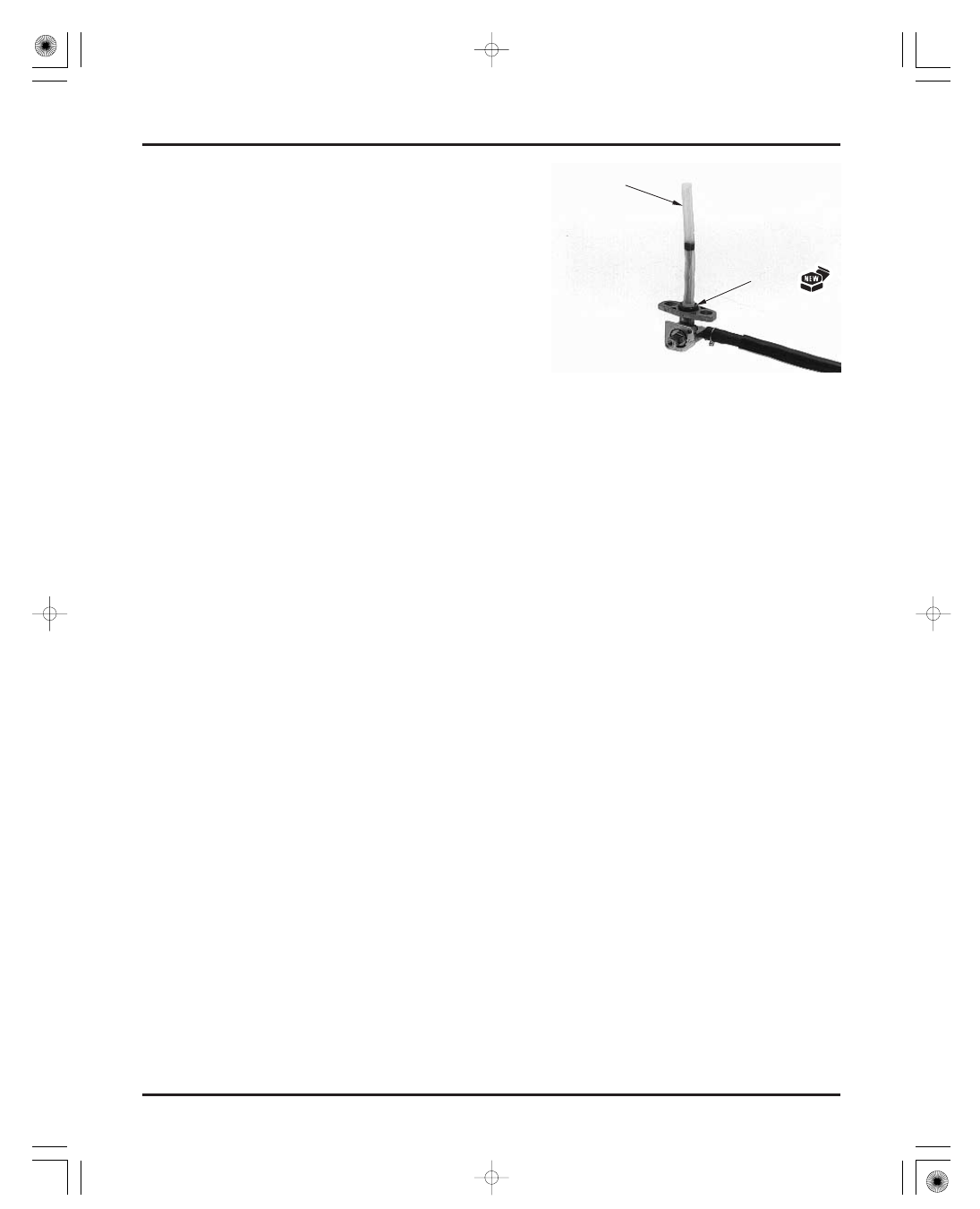
Remove the O-ring.
Clean the strainer screen with non-flammable or
high flash point solvent.
Install a new O-ring onto the fuel valve.
Install the fuel valve into the fuel tank and tighten
the bolts with the collars.
Install the fuel tank.
S
S
T
T
R
R
A
A
I
I
N
N
E
E
R
R
O
O
-
-
R
R
I
I
N
N
G
G
03/01/08 09:28:32 61HN400C_029