ATV Honda TRX350 TM/TE, TRX350 FM/FE. Service Manual - part 5
−
−
−
−
−
−
−
−
−
−
−
−
MAINTENANCE
3-16
FREE PLAY:
FREE PLAY:
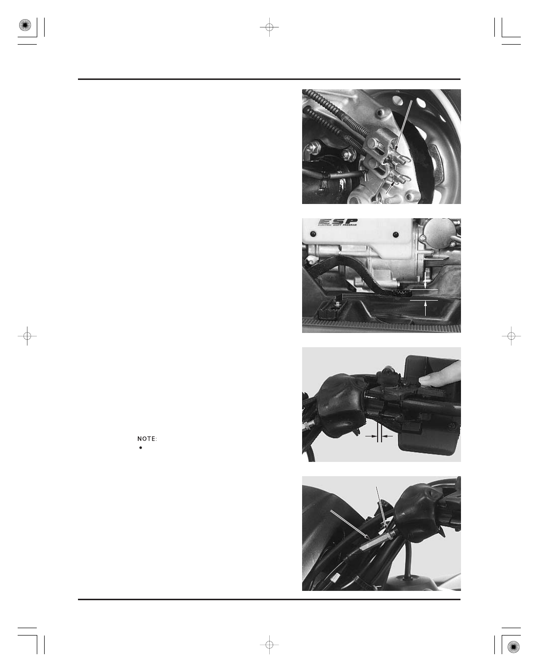
REVERSE LOCK SYSTEM
Adjust the brake lever free play by turning the
upper adjusting nut at the brake arm.
Measure the rear brake pedal free play at the end of
the pedal.
Adjust the brake pedal free play by turning the
lower adjusting nut at the brake arm.
15
20 mm (9/16
13/16 in)
Check the reverse selector cable and lever for loose
connections, excessive play or other damage.
Replace or repair if necessary.
Measure the lever free play at the lever end near
the cable.
If necessary, watch the reverse selector arm on
the crankcase to see when it moves while
determining free play.
2
4 mm (1/16
3/16 in)
Adjust by loosening the lock nut and turning the
adjuster.
Tighten the lock nut.
Install the dust cover securely.
U
U
P
P
P
P
E
E
R
R
A
A
D
D
J
J
U
U
S
S
T
T
I
I
N
N
G
G
N
N
U
U
T
T
L
L
O
O
W
W
E
E
R
R
A
A
D
D
J
J
U
U
S
S
T
T
I
I
N
N
G
G
N
N
U
U
T
T
L
L
O
O
C
C
K
K
N
N
U
U
T
T
A
A
D
D
J
J
U
U
S
S
T
T
E
E
R
R
1
1
5
5
2
2
0
0
m
m
m
m
(
(
9
9
/
/
1
1
6
6
1
1
3
3
/
/
1
1
6
6
i
i
n
n
)
)
2
2
4
4
m
m
m
m
(
(
1
1
/
/
1
1
6
6
3
3
/
/
1
1
6
6
i
i
n
n
)
)
Make sure the
cutout in the
adjusting nut is
seated on the
brake arm joint.
03/01/08 09:21:07 61HN400B_028