Suzuki GSX-R1000. Service Manual - part 15


  Index      Manuals     Suzuki GSX-R1000. Service Manual


Search            copyright infringement  


Content      ..     13      14      15      16     ..


Suzuki GSX-R1000. Service Manual - part 15


1C-6 Engine Electrical Devices: 

TO Sensor Removal and Installation

B947H11306018

Removal

1) Remove the AP sensor. Refer to “AP Sensor 

Removal and Installation” (Page 1C-5).

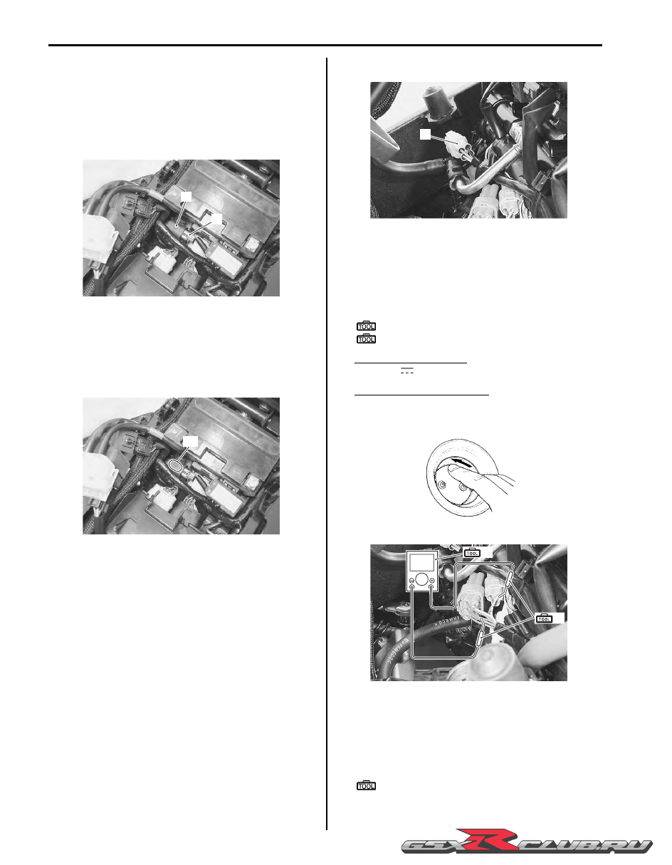
2) Disconnect the coupler (1) and remove the TO 

sensor (2).

Installation

Install the TO sensor in the reverse order of removal. 
Pay attention to the following point:

• When installing the TO sensor, bring the “UP” letters 

“A” upward.

STP Sensor Inspection

B947H11306019

Refer to “DTC “C29” (P1654-H/L): Secondary Throttle 
Position Sensor (STPS) Circuit Malfunction” in Section 
1A (Page 1A-79).

STP Sensor Adjustment

B947H11306020

Adjust the STP sensor in the following procedures:

1) Remove the air cleaner box cover. Refer to “Air 

Cleaner Element Removal and Installation” in 
Section 1D (Page 1D-6).

2) Disconnect the STVA lead wire coupler (1).

3) Insert the needle pointed probes to the STP sensor 

coupler (between Y/W and B/Br wires).

4) Turn the ignition switch ON.

5) Close the secondary throttle valve by finger and 

measure the STP sensor output voltage.

Special tool

(A):  09900–25008 (Multi circuit tester set)
(B):  09900–25009 (Needle-point probe set)

Tester knob indication
Voltage (

)

STP sensor output voltage
ST valve is fully closed: Approx. 0.7 V ((+): Y/W – 
(–): B/Br)

6) Move the throttle body upward by loosing the throttle 

body mounting screws.

7) Loosen the STP sensor mounting screw using the 

special tool and adjust the STP sensor until the 
output voltage comes within the specified value.

Special tool

:  09930–11950 (Torx wrench (5 mm))

1

2

I947H1130016-01

“A”

I947H1130017-01

1

I947H1130018-01

I718H1130017-01

V

(A)

(B)

I947H1130019-01

-------------------------------------------------------------------------------------------------------------------------------------------------------------

Engine Electrical Devices:  1C-7

8) Tighten the STP sensor mounting screw to the 

specified torque.

Tightening torque
STP sensor mounting screw:  3.5 N·m (0.35 kgf-
m, 2.5 lbf-ft)

9) Reinstall the removed parts.

STP Sensor Removal and Installation

B947H11306021

Removal

1) Remove the throttle body. Refer to “Throttle Body 

Removal and Installation” in Section 1D (Page 1D-
10).

2) Remove the STP sensor (1) with the special tool.

Special tool

:  09930–11950 (Torx wrench (5 mm))

NOTE

Prior to disassembly, mark the STP sensor’s 
original position with a paint or scribe for 
accurate reinstallation.


Installation

Install the STP sensor in the reverse order of removal. 
Refer to “Throttle Body Disassembly and Assembly” in 
Section 1D (Page 1D-11).

STV Actuator Inspection

B947H11306022

Refer to “DTC “C28” (P1655): Secondary Throttle Valve 
Actuator (STVA) Malfunction” in Section 1A (Page 1A-
75).

STV Actuator Removal and Installation

B947H11306023

Refer to “Throttle Body Disassembly and Assembly” in 
Section 1D (Page 1D-11).

CAUTION

!


Never remove the STVA from the throttle 
body.


ISC Valve Inspection

B947H11306024

Refer to “DTC “C40” (P0505 / P0506 / P0507): ISC Valve 
Circuit Malfunction” in Section 1A (Page 1A-94).

ISC Valve Removal and Installation

B947H11306025

Refer to “Throttle Body Disassembly and Assembly” in 
Section 1D (Page 1D-11).

CAUTION

!


• Be careful not to disconnect the ISC valve 

coupler at least 5 seconds after ignition 
switch is turned to OFF. If the ECM coupler 
or ISC valve coupler is disconnected 
within 5 seconds after ignition switch is 
turned to OFF, there is a possibility of an 
unusual valve position being written in 
ECM and causing an error of ISC valve 
operation.

• When the throttle body assembly is 

replaced with a new one, the ISC valve 
must be set present position. Refer to “ISC 
Valve Preset and Opening Initialization” 
(Page 1C-8).


I947H1130020-01

1

I947H1130021-01

-------------------------------------------------------------------------------------------------------------------------------------------------------------

1C-8 Engine Electrical Devices: 

ISC Valve Preset and Opening Initialization

B947H11306026

When removing or replacing the ISC valve, set the ISC 
valve to the following procedures:

1) Turn the ignition switch ON.

2) Set up the SDS tool. (Refer to the SDS operation 

manual for further details.)

3) Click the “Active control”.

4) Click the “ISC learned value reset” (1).

5) Click the “Reset” button (2) to clear the ISC leaned 

value.

NOTE

The leaned value of the ISC valve is set at 
Preset position.


6) Close the SDS tool and turn the ignition switch OFF.

NOTE

The ISC valve opening initialization is 
automatically started after the ignition switch 
is turned OFF position.


HO2 Sensor Inspection

B947H11306027

Refer to “DTC “C44” (P0130/P0135): HO2 Sensor 
(HO2S) Circuit Malfunction” in Section 1A (Page 1A-
103).

HO2 Sensor Removal and Installation

B947H11306028

Refer to “Heated Oxygen Sensor (HO2S) Removal and 
Installation” in Section 1B (Page 1B-8).

GP Switch Inspection

B947H11306029

Refer to “Side-stand / Ignition Interlock System Parts 
Inspection” in Section 1I (Page 1I-7)
.

GP Switch Removal and Installation

B947H11306030

Refer to “Gear Position (GP) Switch Removal and 
Installation” in Section 5B (Page 5B-14).

1

I947H1130022-01

2

I947H1130023-01

I947H1130024-01

-------------------------------------------------------------------------------------------------------------------------------------------------------------

Engine Electrical Devices:  1C-9

Specifications

Service Data

B947H11307001

FI Sensors

Tightening Torque Specifications

B947H11307002

Reference:

For the tightening torque of fastener not specified in this section, refer to “Tightening Torque List” in Section 0C 
(Page 0C-9)
.

Item

Standard/Specification

Note

CKP sensor resistance

142 – 194 

CKP sensor peak voltage

0.5 V and more

When cranking

IAP sensor input voltage

4.5 – 5.5 V

IAP sensor output voltage

Approx. 2.7 V at idle speed

TP sensor input voltage

4.5 – 5.5 V

TP sensor output voltage

Closed

Approx. 1.1 V

Opened

Approx. 4.4 V

ECT sensor input voltage

4.5 – 5.5 V

ECT sensor output voltage

0.15 – 4.85 V

ECT sensor resistance

Approx. 2.45 k

 at 20 

°

C (68 

°

F)

IAT sensor input voltage

4.5 – 5.5 V

IAT sensor output voltage

0.15 – 4.85 V

IAT sensor resistance

Approx. 2.58 k

 at 20 

°

C (68 

°

F)

AP sensor input voltage

4.5 – 5.5 V

AP sensor output voltage

Approx. 3.6 V at 100 kPa (760 mmHg)

TO sensor resistance

16.5 – 22.3 k

TO sensor voltage

Normal

0.4 – 1.4 V

Leaning

3.7 – 4.4 V

When leaning 65

°

GP switch voltage

0.6 V and more

From 1st to Top

Injector voltage

Battery voltage

Ignition coil primary peak voltage

80 V and more

When cranking

HO2 sensor output voltage

0.3 V and less at idle speed

0.6 V and more at 5 000 r/min

HO2 sensor heater resistance

6.7 – 9.5 

 at 23 

°

C (73 

°

F)

PAIR control solenoid valve 
resistance

20 – 24 

 at 20 – 30 

°

C (68 – 86 

°

F)

STP sensor input voltage

4.5 – 5.5 V

STP sensor output voltage

Closed

Approx. 0.7 V

Opened

Approx. 4.1 V

STVA resistance

Approx. 6.5 

EVAP system purge control 
solenoid valve resistance

Approx. 32 

 at 20 

°

C (68 

°

F)

E-33 only

ISC valve resistance

Approx. 80 

 at 20 

°

C (68 

°

F)

Fastening part

Tightening torque

Note

N

m

kgf-m

lbf-ft

CMP sensor bolt

10

1.0 

7.0 

)

(Page 1C-2)

TP sensor mounting screw

3.5

0.35 

2.5 

)

(Page 1C-3)

ECT sensor

18

1.8 

13.0 

)

(Page 1C-4)

IAT sensor mounting screw

1.3

0.13 

1.0 

)

(Page 1C-5)

STP sensor mounting screw

3.5

0.35 

2.5 

)

(Page 1C-7)

-------------------------------------------------------------------------------------------------------------------------------------------------------------

1C-10 Engine Electrical Devices: 

Special Tools and Equipment

Special Tool

B947H11308001

09900–25008

09900–25009

Multi circuit tester set

Needle-point probe set

)

(Page 1C-4) / 

)

(Page 1C-

6)

)

(Page 1C-6)

09930–11950

09930–82720

Torx wrench (5 mm)

Mode selection switch

)

(Page 1C-3) / 

)

(Page 1C-

3) / 

)

(Page 1C-6) / 

)

(Page 1C-7)

)

(Page 1C-3)

-------------------------------------------------------------------------------------------------------------------------------------------------------------

Engine Mechanical:  1D-1

Engine

Engine Mechanical

Schematic and Routing Diagram

Camshaft and Sprocket Assembly Diagram

B947H11402001

I947H1140249-02

-------------------------------------------------------------------------------------------------------------------------------------------------------------

1D-2 Engine Mechanical: 

Throttle Cable Routing Diagram

B947H11402002

1

1

1

2

2

2

3

3

3

3

“C”

4

“ a ”

“ a ”

“ a ”

“A”

3

(a)

(a)

“B”

“D”

2

1

I947H1140250-02

1. Throttle cable No. 1

“B”: Pass the clutch cable above the right air intake pipe.

2. Throttle cable No. 2

“C”: Clamp the clutch cable at the white taping point and make sure it 

does not slip out of the clamped position when steering. 
Cut off the excess tip of the clamp.

3. Clutch cable

“D”: Pass the clutch cable outside of the regulator/rectifier harness and 

water bypass hose.

4. Front brake hose

: 4.5 Nm (0.45 kgf-m, 3.0 lbf-ft)

“A”: Pass the throttle cables in front of the front brake hose.

“a”: 0 – 1 mm (0 – 0.04 in)

-------------------------------------------------------------------------------------------------------------------------------------------------------------

Engine Mechanical:  1D-3

Diagnostic Information and Procedures

Engine Mechanical Symptom Diagnosis

B947H11404001

Refer to “Engine Symptom Diagnosis” in Section 1A 
(Page 1A-8)
.

Compression Pressure Check

B947H11404002

The compression pressure reading of a cylinder is a 
good indicator of its internal condition.
The decision to overhaul the cylinder is often based on 
the results of a compression test. Periodic maintenance 
records kept at your dealership should include 
compression readings for each maintenance service.

NOTE

• Before checking the engine for 

compression pressure, make sure that the 
cylinder head nuts are tightened to the 
specified torque values and the valves are 
properly adjusted.

• Make sure that the battery is in fully-

charged condition.


1) Warm up the engine.

2) Lift and support the fuel tank. Refer to “Fuel Tank 

Removal and Installation” in Section 1G (Page 1G-
9)
.

3) Remove the air cleaner box. Refer to “Air Cleaner 

Box Removal and Installation” (Page 1D-7).

4) Remove all the spark plugs. Refer to “Ignition Coil 

and Spark Plug Removal and Installation” in Section 
1H (Page 1H-6).

5) Install the compression gauge and adaptor in the 

spark plug hole. Make sure that the connection is 
tight.

Special tool

(A):  09915–64512 (Compression gauge)
(B):  09915–63311 (Compression gauge 

attachment)

6) Keep the throttle grip in the fully-opened position.

7) Press the starter button and crank the engine for a 

few seconds. Record the maximum gauge reading 
as the cylinder compression.

8) Repeat this procedure with the other cylinders.

Compression pressure specification

Low compression pressure can indicate any of 
the following conditions:

• Excessively worn cylinder walls

• Worn piston or piston rings

• Piston rings stuck in grooves

• Poor valve seating

• Ruptured or otherwise defective cylinder head 

gasket

Overhaul the engine in the following cases:

• Compression pressure in one of the cylinders is 1 

000 kPa (10 kgf/cm

2

, 142 psi) and less.

• The difference in compression pressure between 

any two cylinders is 200 kPa (2 kgf/cm

2

, 28 psi) 

and more.

• All compression pressure readings are below 1 

400 kPa (14 kgf/cm

2

, 199 psi) even when they 

measure 1 000 kPa (10 kgf/cm

2

, 142 psi) and 

more.

9) After checking the compression pressure, reinstall 

the removed parts.

(A)

(B)

I947H1140294-01

Standard

Limit

Difference

1 400 – 1 800 kPa

(14 – 18 kgf/cm

2

199 – 256 psi)

1 000 kPa

(10 kgf/cm

2

142 psi)

200 kPa

(2 kgf/cm

2

28 psi)

I947H1140251-01

-------------------------------------------------------------------------------------------------------------------------------------------------------------

1D-4 Engine Mechanical: 

Repair Instructions

Engine Components Removable with the Engine in Place

B947H11406001

Engine components which can be removed while the engine is installed on the frame are as follows. For the installing 
and removing procedures, refer to respective paragraphs describing each component.

Center of Engine

Item

Removal

Inspection

Installation

Air cleaner element

Refer to “Air Cleaner 
Element Removal and 
Installation” (Page 1D-6).

Refer to “Air Cleaner 
Element Inspection” in 
Section 0B (Page 0B-3).

Refer to “Air Cleaner 
Element Removal and 
Installation” (Page 1D-6).

PAIR control solenoid 
valve

Refer to “PAIR Control 
Solenoid Valve Removal and 
Installation” in Section 1B 
(Page 1B-9)
.

Refer to “PAIR System 
Inspection” in Section 1B 
(Page 1B-9)
.

Refer to “PAIR Control 
Solenoid Valve Removal and 
Installation” in Section 1B 
(Page 1B-9).

Cylinder head cover

Refer to “Engine Top Side 
Disassembly” (Page 1D-26).

Refer to “Engine Top Side 
Assembly” (Page 1D-28).

Camshafts

Refer to “Engine Top Side 
Disassembly” (Page 1D-26).

Refer to “Camshaft 
Inspection” (Page 1D-36).

Refer to “Engine Top Side 
Assembly” (Page 1D-28).

Throttle body

Refer to “Throttle Body 
Removal and Installation” 
(Page 1D-10).

Refer to “Throttle Body 
Inspection and Cleaning” 
(Page 1D-16).

Refer to “Throttle Body 
Removal and Installation” 
(Page 1D-10)
.

Thermostat

Refer to “Thermostat 
Removal and Installation” in 
Section 1F (Page 1F-10).

Refer to “Thermostat 
Inspection” in Section 1F 
(Page 1F-11).

Refer to “Thermostat 
Removal and Installation” in 
Section 1F (Page 1F-10)
.

Crankcase breather cover

Refer to “Crankcase 
Breather (PCV) Hose / Reed 
Valve / Cover Removal and 
Installation” in Section 1B 
(Page 1B-11).

Refer to “Crankcase 
Breather (PCV) Cover 
Inspection” in Section 1B 
(Page 1B-12).

Refer to “Crankcase 
Breather (PCV) Hose / Reed 
Valve / Cover Removal and 
Installation” in Section 1B 
(Page 1B-11)
.

Starter motor

Refer to “Starter Motor 
Removal and Installation” in 
Section 1I (Page 1I-4)
.

Refer to “Starter Motor 
Inspection” in Section 1I 
(Page 1I-5)
.

Refer to “Starter Motor 
Removal and Installation” in 
Section 1I (Page 1I-4).

Oil filter

Refer to “Engine Oil and 
Filter Replacement” in 
Section 0B (Page 0B-10).

Refer to “Engine Oil and 
Filter Replacement” in 
Section 0B (Page 0B-10).

Oil cooler

Refer to “Oil Cooler / Oil 
Cooler Hose Removal and 
Installation” in Section 1E 
(Page 1E-8)
.

Refer to “Oil Cooler / Oil 
Cooler Hose Removal and 
Installation” in Section 1E 
(Page 1E-8).

Exhaust pipe/Muffler

Refer to “Muffler / Muffler 
Chamber / Exhaust Pipe 
Removal and Installation” in 
Section 1K (Page 1K-11).

Refer to “Exhaust System 
Inspection” in Section 1K 
(Page 1K-13).

Refer to “Muffler / Muffler 
Chamber / Exhaust Pipe 
Removal and Installation” in 
Section 1K (Page 1K-11).

-------------------------------------------------------------------------------------------------------------------------------------------------------------

Engine Mechanical:  1D-5

Engine Right Side

Item

Removal

Inspection

Installation

Cam chain tension adjuster

Refer to “Engine Top Side 
Disassembly” (Page 1D-26).

Refer to “Cam Chain Tension 
Adjuster Inspection” 
(Page 1D-38)
.

Refer to “Engine Top Side 
Assembly” (Page 1D-28)
.

Clutch cover

Refer to “Clutch Removal” in 
Section 5C (Page 5C-5)
.

Refer to “Clutch Installation” 
in Section 5C (Page 5C-7).

Clutch plates

Refer to “Clutch Removal” in 
Section 5C (Page 5C-5)
.

Refer to “Clutch Parts 
Inspection” in Section 5C 
(Page 5C-11)
.

Refer to “Clutch Installation” 
in Section 5C (Page 5C-7).

Clutch sleeve hub

Refer to “Clutch Removal” in 
Section 5C (Page 5C-5)
.

Refer to “Clutch Installation” 
in Section 5C (Page 5C-7).

Primary driven gear

Refer to “Clutch Removal” in 
Section 5C (Page 5C-5)
.

Refer to “Clutch Parts 
Inspection” in Section 5C 
(Page 5C-11)
.

Refer to “Clutch Installation” 
in Section 5C (Page 5C-7).

Oil pump drive sprocket

Refer to “Engine Bottom 
Side Disassembly” 
(Page 1D-49)
.

Refer to “Engine Bottom 
Side Assembly” (Page 1D-
56).

Gearshift shaft

Refer to “Gearshift Shaft / 
Gearshift Cam Plate 
Removal and Installation” in 
Section 5B (Page 5B-17).

Refer to “Gearshift Linkage 
Inspection” in Section 5B 
(Page 5B-20).

Refer to “Gearshift Shaft / 
Gearshift Cam Plate 
Removal and Installation” in 
Section 5B (Page 5B-17).

CKP sensor rotor/Cam 
chain drive sprocket

Refer to “Engine Bottom 
Side Disassembly” 
(Page 1D-49)
.

Refer to “Engine Bottom 
Side Assembly” (Page 1D-
56).

Cam chain tensioner

Refer to “Engine Bottom 
Side Disassembly” 
(Page 1D-49)
.

Refer to “Cam Chain 
Tensioner Inspection” 
(Page 1D-40)
.

Refer to “Engine Bottom 
Side Assembly” (Page 1D-
56).

CKP sensor

Refer to “CKP Sensor 
Removal and Installation” in 
Section 1C (Page 1C-2)
.

Refer to “CKP Sensor 
Inspection” in Section 1C 
(Page 1C-2).

Refer to “CKP Sensor 
Removal and Installation” in 
Section 1C (Page 1C-2)
.

Starter idle gear

Refer to “Starter Clutch 
Removal and Installation” in 
Section 1I (Page 1I-10)
.

Refer to “Starter Clutch 
Removal and Installation” in 
Section 1I (Page 1I-10)
.

Starter clutch

Refer to “Starter Clutch 
Removal and Installation” in 
Section 1I (Page 1I-10)
.

Refer to “Starter Clutch 
Inspection” in Section 1I 
(Page 1I-11).

Refer to “Starter Clutch 
Removal and Installation” in 
Section 1I (Page 1I-10)
.

Starter torque limiter

Refer to “Starter Torque 
Limiter Removal and 
Installation” in Section 1I 
(Page 1I-9)
.

Refer to “Starter Torque 
Limiter Inspection” in Section 
1I (Page 1I-10)
.

Refer to “Starter Torque 
Limiter Removal and 
Installation” in Section 1I 
(Page 1I-9).

-------------------------------------------------------------------------------------------------------------------------------------------------------------

1D-6 Engine Mechanical: 

Engine Left Side

Air Cleaner Element Removal and Installation

B947H11406002

Removal

1) Lift and support the fuel tank. Refer to “Fuel Tank 

Removal and Installation” in Section 1G (Page 1G-
9).

2) Remove the air cleaner box cover (1).

3) Remove the air cleaner element (2).

Installation 

Installation is in the reverse order of removal.

Item

Removal

Inspection

Installation

Speed sensor

Refer to “Speed Sensor 
Removal and Installation” in 
Section 9C (Page 9C-5).

Refer to “Speed Sensor 
Inspection” in Section 9C 
(Page 9C-6).

Refer to “Speed Sensor 
Removal and Installation” in 
Section 9C (Page 9C-5).

Engine sprocket

Refer to “Engine Sprocket 
Removal and Installation” in 
Section 3A (Page 3A-2)
.

Refer to “Drive Chain 
Related Parts Inspection” in 
Section 3A (Page 3A-5)
.

Refer to “Engine Sprocket 
Removal and Installation” in 
Section 3A (Page 3A-2)
.

Drive chain

Refer to “Drive Chain 
Replacement” in Section 3A 
(Page 3A-7).

Refer to “Drive Chain 
Inspection and Adjustment” 
in Section 0B (Page 0B-14).

Refer to “Drive Chain 
Replacement” in Section 3A 
(Page 3A-7).

Gear position switch

Refer to “Gear Position (GP) 
Switch Removal and 
Installation” in Section 5B 
(Page 5B-14).

Refer to “Gear Position (GP) 
Switch Inspection” in Section 
5B (Page 5B-13).

Refer to “Gear Position (GP) 
Switch Removal and 
Installation” in Section 5B 
(Page 5B-14).

Generator cover

Refer to “Generator Removal 
and Installation” in Section 
1J (Page 1J-4).

Refer to “Generator Removal 
and Installation” in Section 
1J (Page 1J-4).

Generator rotor

Refer to “Generator Removal 
and Installation” in Section 
1J (Page 1J-4).

Refer to “Generator Removal 
and Installation” in Section 
1J (Page 1J-4).

Water pump

Refer to “Water Pump 
Removal and Installation” in 
Section 1F (Page 1F-13).

Refer to “Water Pump 
Related Parts Inspection” in 
Section 1F (Page 1F-17)
.

Refer to “Water Pump 
Removal and Installation” in 
Section 1F (Page 1F-13)
.

Oil pressure switch

Refer to “Oil Pressure Switch 
Removal and Installation” in 
Section 1E (Page 1E-9)
.

Refer to “Oil Pressure 
Indicator Inspection” in 
Section 9C (Page 9C-6)
.

Refer to “Oil Pressure Switch 
Removal and Installation” in 
Section 1E (Page 1E-9)
.

1

I947H1140001-02

2

I947H1140002-01

-------------------------------------------------------------------------------------------------------------------------------------------------------------

Engine Mechanical:  1D-7

Air Cleaner Box Removal and Installation

B947H11406003

Removal

1) Lift and support the fuel tank. Refer to “Fuel Tank 

Removal and Installation” in Section 1G (Page 1G-
9)
.

2) Remove the air cleaner box cover. Refer to “Air 

Cleaner Element Removal and Installation” 
(Page 1D-6).

3) Remove the air cleaner mounting bolt.

4) Remove the air cleaner box bolt.

5) Disconnect the IAT sensor coupler (1), PCV hose (2) 

and PAIR hose (3).

6) Disconnect ISC hose (4) and IAP sensor (5).

7) Remove the air cleaner box.

Installation

Install the air cleaner box in the reverse order of 
removal. Pay attention to the following point:

• Route the hoses properly. Refer to “Throttle Body 

Construction” (Page 1D-9).

• Tighten air cleaner box bolts in the ascending order. 

Refer to “Throttle Body Construction” (Page 1D-9).

Air Cleaner Element Inspection and Cleaning

B947H11406004

Refer to “Air Cleaner Element Inspection” in Section 0B 
(Page 0B-3)
.

Throttle Cable Removal and Installation

B947H11406005

Removal

1) Remove the air cleaner box. Refer to “Air Cleaner 

Box Removal and Installation” (Page 1D-7).

2) Remove the right handlebar switch box. Refer to 

“Handlebar Removal and Installation” in Section 6B 
(Page 6B-2).

3) Remove the throttle cables as shown in the cable 

routing diagram. Refer to “Throttle Cable Routing 
Diagram” (Page 1D-2)
.

Installation

Install the throttle cables in the reverse order of removal. 
Pay attention to the following points:

• Install the throttle cables as shown in the cable routing 

diagram. Refer to “Throttle Cable Routing Diagram” 
(Page 1D-2).

• Check the throttle cable play and proper operation. 

Refer to “Throttle Cable Play Inspection and 
Adjustment” in Section 0B (Page 0B-12).

Throttle Cable Inspection

B947H11406006

Check that the throttle grip moves smoothly from full 
open to full close. If it does not move smoothly, lubricate 
the throttle cables.

Throttle Cable Play Inspection and Adjustment

B947H11406007

Refer to “Throttle Cable Play Inspection and Adjustment” 
in Section 0B (Page 0B-12).

I947H1140003-01

I947H1140004-01

1

2

3

I947H1140005-01

5

4

I947H1140006-01

-------------------------------------------------------------------------------------------------------------------------------------------------------------

1D-8 Engine Mechanical: 

Throttle Body Components

B947H11406008

[A]

1

1

2

3

3

3

3

3

3

3

5

6

7

8

9

11

10

4

(a)

(a)

(a)

(a)

(b)

8

12

(d)

(c)

FWD

FWD

I947H1140252-03

1. Fuel delivery pipe

6. Secondary fuel injector

11. Vacuum hose

: 6.5 Nm (0.65 kgf-m, 4.5 lbf-ft)

2. Fuel delivery pipe T-joint

7. Primary fuel injector

12. EVAP system purge control solenoid valve

: 10 Nm (1.0 kgf-m, 7.0 lbf-ft)

3. O-ring

8. Cushion seal

[A]: For E-33 only

: Apply engine oil.

4. TP sensor

9. ISC valve

: 3.5 Nm (0.35 kgf-m, 2.5 lbf-ft)

: Do not reuse.

5. STP sensor

10. Air screw

: 2 Nm (0.2 kgf-m, 1.5 lbf-ft)

-------------------------------------------------------------------------------------------------------------------------------------------------------------

Engine Mechanical:  1D-9

Throttle Body Construction

B947H11406009

1

2

3

5

“I”

“C”

“D”

“G”

“E”

“F”

4

“H”

“H”

“A”

“G”

(a)

(b)

(c)

(d)

(d)

(d)

(e)

(f)

FWD

“K”

“B”

“7”
“1”

“1” “6”

“3”

“2”

“2”

“3”

“4”

“4”

“6”

“5”

“5”

“J”

(g)

6

I947H1140253-03

1. Intake pipe

“C”: Face the end of clamps upward and keep clearance 

from the seat rail and fuel tank.

“K”: Face the clamp end right side.

2. EVAP system purge control solenoid valve 

(E-33 only)

“D”: Arrange the hose and wiring harnesses in parallel to 

the frame bridge.

: 8.5  N

m (0.85 kgf-m, 6.5 lbf-ft)

3. EVAP canister (E-33 only)

“E”: Yellow paint should face downward.

: 1.5 N

m (0.15 kgf-m, 1.0 lbf-ft)

4. IAT sensor

“F”: Face the clamp end backward.

: 7 N

m (0.7 kgf-m, 5.0 lbf-ft)

5. ISC valve hose

“G”: Face the clamp end downward.

: 10 N

m (1.0 kgf-m, 7.0 lbf-ft)

6. HO2 sensor

“H”: Tighten the bolts in the ascending of numbers.

: 1.3 N

m (0.13 kgf-m, 1.0 lbf-ft)

“A”: Face the clamp end left side.

“I”: Route the fuel pump lead wire above the fuel nipple.

: 4.3 N

m (0.43 kgf-m, 3.0 lbf-ft)

“B”: Yellow marking should face upward.

“J”: Pass the HO2 sensor lead wire between the frame 

and engine.

: 25 N

m (2.5 kgf-m, 18.0 lbf-ft)

-------------------------------------------------------------------------------------------------------------------------------------------------------------

1D-10 Engine Mechanical: 

Throttle Body Removal and Installation

B947H11406010

Removal

1) Remove the side cowlings. Refer to “Exterior Parts 

Removal and Installation” in Section 9D (Page 9D-
6).

2) Remove the air cleaner box. Refer to “Air Cleaner 

Box Removal and Installation” (Page 1D-7).

3) Remove the clamps (1).

4) Disconnect the IAP sensor (2) from the vacuum 

hose.

5) Disconnect the STVA lead wire coupler (3).

6) Disconnect secondary fuel injector couplers (4) and 

primary fuel injector couplers (5).

7) Disconnect the purge hose (6) from the EVAP 

system purge control solenoid valve. (E-33 only)

8) Remove the clamp (7).

9) Disconnect the ISC valve coupler (8).

10) Place a rag under the fuel feed hose (9) and 

disconnect the fuel feed hose from the fuel pump.

WARNING

!


For E-33 models, drain fuel from the fuel tank 
before disconnecting the fuel feed hose to 
prevent fuel leakage.


11) Loosen the throttle body clamp screws, left and right.

12) Lift up the throttle body from the intake pipes.

13) Disconnect the STP sensor coupler (10) and TP 

sensor coupler (11).

1

1

2

3

5

6

4

4

I947H1140254-01

7

8

I947H1140255-01

9

I947H1140007-02

I947H1140256-01

11

10

I947H1140257-02

-------------------------------------------------------------------------------------------------------------------------------------------------------------

Engine Mechanical:  1D-11

14) Disconnect the throttle cables.

CAUTION

!


After disconnecting the throttle cables, do 
not snap the throttle valve from full open to 
full close. It may cause damage to the throttle 
valve and throttle body.


15) Remove the throttle body.

Installation

Installation is in the reverse order of removal. Pay 
attention to the following points:

• Connect the primary injector couplers (1) and 

secondary injector couplers (2) to the respective fuel 
injectors. Make sure that each coupler is installed in 
the correct position. The color on each lead wire 
refers to the appropriate fuel injector.

• Connect the throttle cable No. 1 (3) and throttle cable 

No. 2 (4) to the throttle cable drum.

• Loosen each throttle cable lock-nut.

• Turn in each throttle cable adjuster fully and locate 

each outer cable so that the clearance “a” is 0 – 1 mm 
(0 – 0.04 in).

• Tighten each lock-nut.

Tightening torque
Throttle cable lock-nut:  4.5 N·m (0.45 kgf-m, 3.0 
lbf-ft)

• Adjust the throttle cable play. Refer to “Throttle Cable 

Play Inspection and Adjustment” in Section 0B 
(Page 0B-12).

• Reset the ISC valve and TP sensor learned values. 

Refer to “ISC Valve Reset” (Page 1D-18) and “TP 
Reset” (Page 1D-19).

Throttle Body Disassembly and Assembly

B947H11406011

Refer to “Throttle Body Removal and Installation” 
(Page 1D-10).

Disassembly

CAUTION

!


Identify the position of each removed part. 
Organize the parts in their respective groups 
so that they can be reinstalled in their 
original positions.


1) Disconnect the fuel feed hose (1), ISC valve hose (2) 

and vacuum hoses (3).

Primary injector

Secondary injector

#1

Y/R and Gr/W

Y/R and Lg

#2

Y/R and Gr/B

Y/R and Lg/W

#3

Y/R and Gr/Y

Y/R and Lg/B

#4

Y/R and Gr/R

Y/R and Lg/Bl

I947H1140258-01

1

2

I947H1140259-01

“a”: 0 – 1 mm (0 – 0.04 in)

3

4

“ a ”

“ a ”

I837H1140016-01

-------------------------------------------------------------------------------------------------------------------------------------------------------------


Content      ..     13      14      15      16     ..