Suzuki GSX-R1000. Service Manual - part 16


  Index      Manuals     Suzuki GSX-R1000. Service Manual


Search            copyright infringement  


Content      ..     14      15      16      17     ..


Suzuki GSX-R1000. Service Manual - part 16


1D-12 Engine Mechanical: 

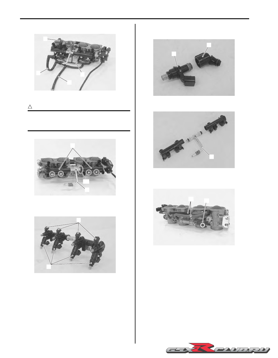
2) Disconnect the purge hose (4). (E-33 only)

3) Remove the fuel delivery pipe assembly (5).

CAUTION

!


Be careful not to twist the fuel delivery pipes 
and T-joint (6) when removing them, or joint 
part “A” of the fuel delivery pipe get damage.


4) Remove the primary fuel injectors (7) and secondary 

fuel injectors (8) from the fuel delivery pipes.

5) Remove the fuel pipe (9) from the primary fuel 

injectors (7).

6) Remove the T-joint (6) from the fuel delivery pipes.

7) Remove the ISC valve hoses (10) and ISC valve 

(11).

1

2

3

4

I947H1140299-01

5

6

“A”

I947H1140008-01

7

8

I947H1140009-01

7

9

I947H1140010-01

6

I947H1140011-01

11

10

I947H1140012-01

-------------------------------------------------------------------------------------------------------------------------------------------------------------

Engine Mechanical:  1D-13

8) Remove the TP sensor (12) and STP sensor (13) 

with the special tool.

Special tool

:  09930–11950 (Torx wrench (5 mm))

NOTE

Prior to disassembly, mark each sensor’s 
original position with a paint or scribe for 
accurate reinstallation.


CAUTION

!


Never remove the STVA (14) from the throttle 
body.


CAUTION

!


Never remove the throttle valves (15) and 
secondary throttle valves (16).


CAUTION

!


• These adjusting screws (17), (18) and (19) 

are factory-adjusted at the time of delivery 
and do not turn or remove them.

• Do not separate the throttle body.


Assembly

Reassemble the throttle body in the reverse order of 
disassembly. Pay attention to the following points:

• With the secondary throttle valves fully opened, install 

the STP sensor (Black) and tighten the STP sensor 
mounting screw to the specified torque.

NOTE

• Apply thin coat of engine oil to the O-ring.

• Align the secondary throttle valve shaft 

end “A” with the groove “B” of the STP 
sensor.

• Apply grease to the secondary throttle 

valve shaft end “A” if necessary.


:  Grease 99000–25010 (SUZUKI SUPER 

GREASE “A” or equivalent)

Special tool

:  09930–11950 (Torx wrench (5 mm))

Tightening torque
STP sensor mounting screw:  3.5 N·m (0.35 kgf-
m, 2.5 lbf-ft)

12

13

I947H1140013-01

14

I947H1140014-01

15

16

I947H1140015-01

17

18

19

I947H1140016-01

“A”

“B”

I947H1140017-01

-------------------------------------------------------------------------------------------------------------------------------------------------------------

1D-14 Engine Mechanical: 

NOTE

• Make sure the secondary throttle valves 

smoothly open and close.

• If necessary, adjust the STP sensor. Refer 

to “STP Sensor Adjustment” in Section 1C 
(Page 1C-6).


• With the throttle valves fully closed, install the TP 

sensor (Gray) and tighten the TP sensor mounting 
screw to the specified torque.

CAUTION

!


• Apply thin coat of engine oil to the O-ring.

• Align the throttle valve shaft end “C” with 

the groove “D” of the TP sensor.

• Apply grease to the throttle valve shaft end 

“C” if necessary.


:  Grease 99000–25010 (SUZUKI SUPER 

GREASE “A” or equivalent)

Special tool

:  09930–11950 (Torx wrench (5 mm))

Tightening torque
TP sensor mounting screw:  3.5 N·m (0.35 kgf-m, 
2.5 lbf-ft)

NOTE

• Make sure the throttle valves smoothly 

open and close.

• If necessary, adjust the TP sensor. Refer to 

“TP Sensor Adjustment” in Section 1C 
(Page 1C-3).


• Apply a thin coat of engine oil to the O-ring, install the 

ISC valve to the throttle body and tighten the ISC 
valve mounting screw to the specified torque.

Special tool

:  09930–11960 (Torx wrench (4 mm))

Tightening torque
ISC valve mounting screw (a):  2 N·m (0.2 kgf-m, 
1.5 lbf-ft)

I947H1140018-01

“C”

“D”

I947H1140019-01

I947H1140020-01

(a)

I947H1140021-01

-------------------------------------------------------------------------------------------------------------------------------------------------------------

Engine Mechanical:  1D-15

• Apply thin coat of engine oil to the new O-rings (1) and 

cushion seals (2).

CAUTION

!


Replace the O-rings and cushion seals with 
new ones.


• Assemble the fuel delivery pipes so the T-joint is set in 

proper angle as shown in the figure.

CAUTION

!


Be careful not to twist the fuel delivery pipes 
and T-joint when installing them, or joint part 
“E” of the fuel delivery pipe may get damage.


• Install each fuel injector by pushing it straight to the 

delivery pipe.

CAUTION

!


Never turn the injector while pushing it.


NOTE

Align the coupler “F” of injector with boss 
“G” of the delivery pipe.


• Install the fuel delivery pipe assembly to the throttle 

body.

• Tighten the fuel delivery pipe mounting screws to the 

specified torque.

Tightening torque
Fuel delivery pipe mounting screw (b):  3.5 N·m (
0.35 kgf-m, 2.5 lbf-ft)

• Connect the hoses properly. Refer to “Throttle Body 

Construction” (Page 1D-9).

1

1

2

2

I947H1140022-01

1

I947H1140023-01

“E”

I947H1140024-01

“F”

“F”

“G”

“G”

I947H1140025-01

(b)

(b)

I947H1140026-01

-------------------------------------------------------------------------------------------------------------------------------------------------------------

1D-16 Engine Mechanical: 

Throttle Body Inspection and Cleaning

B947H11406012

Refer to “Throttle Body Disassembly and Assembly” 
(Page 1D-11).

Cleaning

WARNING

!


Some carburetor cleaning chemicals, 
especially dip-type soaking solutions, are 
very corrosive and must be handled carefully. 
Always follow the chemical manufacturer’s 
instructions on proper use, handling and 
storage.


• Clean passageways with a spray-type carburetor 

cleaner and blow dry with compressed air.

CAUTION

!


Never clean the throttle body main bore. Do 
not use wire to clean passageways. Wire can 
damage passageways. If the components 
cannot be cleaned with a spray cleaner it may 
be necessary to use a dip-type cleaning 
solution and allow them to soak. Always 
follow the chemical manufacturer’s 
instructions for proper use and cleaning of 
the throttle body components. Do not apply 
carburetor cleaning chemicals to the rubber 
and plastic materials.


Inspection

Check following items for any defects or clogging. 
Replace the damaged part if necessary.

• O-rings

• Throttle valves

• Secondary throttle valves

• Vacuum hoses

• ISC valve hoses

• Fuel delivery pipes

• Cushion seals

• Fuel injectors

ISC Valve Visual Inspection

B947H11406013

Visually inspect the ISC valve if necessary.

• Inspect the ISC valve for any carbon deposition 

defects. Clean or replace the ISC valve if necessary.

Throttle Valve Synchronization

B947H11406014

Check and adjust the throttle valve synchronization 
among four cylinders.

1) Start the engine and run it in idling condition for 

warming up.

2) Stop the warmed-up engine.

3) Lift and support the fuel tank. Refer to “Fuel Tank 

Removal and Installation” in Section 1G (Page 1G-
9).

4) Remove the clamps (1).

I947H1140027-01

1

I947H1140308-01

-------------------------------------------------------------------------------------------------------------------------------------------------------------

Engine Mechanical:  1D-17

5) Disconnect the respective vacuum hoses (2) from 

vacuum nipples on the throttle body.

6) Disconnect the IAP sensor coupler (3).

7) Connect the respective vacuum tester hoses (4) to 

the vacuum nipples.

8) Set up the SDS tool. (Refer to the SDS operation 

manual for further details.)

9) Start the engine.

10) Click “Data monitor”.

11) Warm up the engine (Engine coolant temp. more 

than 80 

°

C (176 

°

F)).

12) Click “Active control”.

13) Click “ISC air volume control” (5).

14) Click “ON” button (6) to fix the ISC air volume of four cylinders.

NOTE

When making this synchronization, be sure that the engine coolant temperature is within 80 – 100 

°

(176 – 212 

°

F).


3

2

I947H1140309-01

4

I947H1140310-01

I947H1140311-01

5

I947H1140300-02

6

“A”

“B”

I947H1140312-01

“A”: Engine speed: Approx 1 150 rpm

“B”: ISC valve position: Approx 48 step

-------------------------------------------------------------------------------------------------------------------------------------------------------------

1D-18 Engine Mechanical: 

15) Check for the synchronization of vacuum from #1 to 

#4 cylinders.

16) Equalize the vacuum of the cylinders by turning each 

air screw (7) and keep it running at idling speed.

NOTE

Always set the engine rpm at idle rpm.


17) If the adjustment is not yet correct, remove each air 

screw and clean them with a spray-type carburetor 
cleaner and blow dry with a compressed air. Also, 
clean the air screw passageways.

NOTE

• Slowly turn the air screw clockwise and 

count the number of turns until the screw 
is lightly seated.

• Make a note of how many turns were made 

so the screw can be reset correctly after 
cleaning.


18) Repeat the procedures from 9) to 16).

19) Close the SDS tool and turn the ignition switch OFF.

20) Disconnect the vacuum tester and reinstall the 

removed parts.

21) After completing the throttle valve synchronization, 

clear the DTC and reset the ISC learned value using 
SDS tool. Refer to “ISC Valve Preset and Opening 
Initialization” in Section 1C (Page 1C-8).

ISC Valve Reset

B947H11406015

When removing or replacing the throttle body assembly, 
reset the ISC valve learned value in the following 
procedures:

1) Turn the ignition switch ON position.

2) Set up the SDS tools. (Refer to the SDS operation 

manual for further details.)

3) Click “Active control”.

4) Click “ISC learned value reset” (1).

5) Click “Reset” button (2) to clear the ISC learned 

value.

I947H1140313-01

7

I947H1140314-01

1

I947H1140301-01

2

I947H1140302-01

-------------------------------------------------------------------------------------------------------------------------------------------------------------

Engine Mechanical:  1D-19

NOTE

The learned value of the ISC valve is set at 
RESET position.


6) Close the SDS tool.

7) Turn the ignition switch OFF position.

NOTE

The ISC valve opening initialization is 
automatically started after the ignition switch 
is turned OFF.


TP Reset

B947H11406016

When replacing the throttle body assembly or TP sensor 
with a new one or reinstalling the TP sensor, reset the 
TP learned value in the following procedures:

NOTE

Keep the throttle valves fully closed while 
resetting the TP learned value.


1) Turn the ignition switch ON.

2) Set up the SDS tool. (Refer to the SDS operation 

manual for further details.)

3) Click the “Active control”.

4) Click the “TP learned value reset” (1).

5) Click the “Reset” button (2) to clear the TP learned 

value.

NOTE

The leaned value of the TP sensor is set at 
Preset position.


6) Close the SDS tool and turn the ignition switch OFF.

I947H1140303-01

1

I947H1140304-01

2

I947H1140305-01

I947H1140306-01

-------------------------------------------------------------------------------------------------------------------------------------------------------------

1D-20 Engine Mechanical: 

Engine Assembly Removal

B947H11406017

Before taking the engine out of the frame, wash the 
engine using a steam cleaner. Engine removal is 
sequentially explained in the following steps:

1) Remove the side cowlings. Refer to “Exterior Parts 

Removal and Installation” in Section 9D (Page 9D-
6).

2) Remove the front seat. Refer to “Exterior Parts 

Removal and Installation” in Section 9D (Page 9D-
6).

3) Disconnect the battery (–) lead wire (1).

4) Jack up the motorcycle and fix it for safety.

5) Drain engine oil. Refer to “Engine Oil and Filter 

Replacement” in Section 0B (Page 0B-10).

6) Drain engine coolant. Refer to “Engine Oil and Filter 

Replacement” in Section 0B (Page 0B-10).

7) Lift and support the fuel tank. Refer to “Fuel Tank 

Removal and Installation” in Section 1G (Page 1G-
9).

8) Remove the air cleaner box. Refer to “Air Cleaner 

Box Removal and Installation” (Page 1D-7).

9) Remove the throttle body assembly. Refer to 

“Throttle Body Removal and Installation” (Page 1D-
10).

10) Remove the oil cooler and hoses. Refer to “Oil 

Cooler / Oil Cooler Hose Removal and Installation” in 
Section 1E (Page 1E-8).

11) Remove the radiator assembly. Refer to “Radiator / 

Cooling Fan Motor Removal and Installation” in 
Section 1F (Page 1F-6)
.

12) Disconnect the water/air bleed hose (2) and radiator 

inlet hose (3).

13) Remove the horn (4) and radiator heat guard (5).

14) Remove the radiator/oil cooler mounting bracket (6).

1

I947H1140260-02

2

3

I947H1140261-01

5

4

I947H1140262-01

6

I947H1140263-01

-------------------------------------------------------------------------------------------------------------------------------------------------------------

Engine Mechanical:  1D-21

15) Remove the exhaust system components. Refer to 

“Muffler / Muffler Chamber / Exhaust Pipe Removal 
and Installation” in Section 1K (Page 1K-11).

16) Remove the clamp (7).

17) Disconnect the oil pressure switch lead wire coupler 

(8), generator lead wire coupler (9) and ECT sensor 
coupler (10).

18) Disconnect the GP switch lead wire coupler (11).

19) Disconnect the starter motor lead wire (12) and 

engine ground lead wire (13).

20) Disconnect the CKP sensor lead wire coupler (14).

21) Remove the crankcase breather (PCV) hose (15).

22) Disconnect the PAIR solenoid valve coupler (16).

23) Disconnect the CMP sensor lead wire coupler (17) 

and ignition coil couplers (18).

24) Remove the ignition coils.

CAUTION

!


• Do not remove the ignition coil before 

disconnecting its coupler.

• Do not pry up the ignition coil/plug cap 

with a screwdriver or a bar to avoid its 
damage.

• Be careful not to drop the ignition coil/plug 

cap to prevent its short or open circuit.


7

8

9

10

I947H1140264-01

11

I947H1140265-01

12

13

I947H1140266-02

14

15

I947H1140267-03

16

I947H1140268-01

17

18

I947H1140269-02

-------------------------------------------------------------------------------------------------------------------------------------------------------------

1D-22 Engine Mechanical: 

25) Remove the engine sprocket cover (19). Refer to 

“Engine Sprocket Removal and Installation” in 
Section 3A (Page 3A-2).

26) Remove the dowel pins and clutch push rod (20).

27) Remove the engine sprocket (21). Refer to “Engine 

Sprocket Removal and Installation” in Section 3A 
(Page 3A-2).

28) Support the engine using an engine jack.

29) Loosen the engine mounting pinch bolts (22) (RH).

30) Remove the engine mounting bolts (23) (RH).

31) Remove the engine mounting bolts (24) (LH).

32) Remove the engine mounting nut (25).

33) Remove the engine mounting thrust adjuster lock-

nut (26) with the special tool.

19

I947H1140271-02

20

I947H1140272-03

21

I947H1140273-02

I947H1140274-01

24

23

22

I947H1140275-02

-------------------------------------------------------------------------------------------------------------------------------------------------------------

Engine Mechanical:  1D-23

34) Loosen the engine mounting thrust adjuster (27) 

fully.

Special tool

(A):  09940–14990 (Engine mounting adjust 

wrench)

NOTE

Do not remove the engine mounting bolt at 
this stage.


35) Remove the engine mounting nut (28).

36) Loosen the engine mounting thrust adjuster lock-nut 

(29) with the special tool.

37) Loosen the engine mounting thrust adjuster (30) 

fully.

Special tool

(A):  09940–14990 (Engine mounting adjust 

wrench)

NOTE

Do not remove the engine mounting bolt at 
this stage.


38) Remove the engine mounting bolts and gradually 

lower the front side of the engine. Then, take off the 
drive chain from the driveshaft.

39) Remove the engine assembly.

25

I947H1140276-03

(A)

27

I947H1140277-03

25

26

27

I947H1140278-02

28

I947H1140279-03

(A)

30

I947H1140280-03

28

29

30

I947H1140281-02

-------------------------------------------------------------------------------------------------------------------------------------------------------------

1D-24 Engine Mechanical: 

Engine Assembly Installation

B947H11406018

Install the engine in the reverse order of engine removal. 
Pay attention to the following points:

• Before installing the engine, install the collars (1).

• Before installing the engine, install the engine 

mounting thrust adjusters (2).

• Gradually raise the rear side of the engine assembly, 

and then put the drive chain on the driveshaft.

CAUTION

!


Be careful not to catch the wiring harness 
between the frame and the engine.


• Install all engine mounting bolts and tighten them 

temporarily.

• Tighten the engine mounting thrust adjusters (2) to the 

specified torque.

Tightening torque
Engine mounting thrust adjuster (a):  23 N·m (2.3 
kgf-m, 16.5 lbf-ft)

• Tighten the engine mounting thrust adjuster lock-nuts 

(3) to the specified torque with the special tool.

Tightening torque
Engine mounting thrust adjuster lock-nut (b):  45 
N·m (4.5 kgf-m, 32.5 lbf-ft)

Special tool

(A):  09940–14990 (Engine mounting adjust 

wrench)

1

I947H1140282-01

2

I947H1140283-01

I947H1140284-01

(a)

2

I947H1140285-02

(a)

2

I947H1140286-02

(A)

(b)

3

I947H1140287-02

(A)

(b)

3

I947H1140288-02

-------------------------------------------------------------------------------------------------------------------------------------------------------------

Engine Mechanical:  1D-25

• Tighten all engine mounting bolts and nuts to the 

specified torque, as shown in the following illustration.

NOTE

The engine mounting nuts are self-locking. 
Once the nuts have been removed, they are 
no longer of any use.


• Tighten the engine mounting pinch bolt to the 

specified torque, as shown in the following illustration.

RH

LH

(a)

8

A

A, B

C, D

E, F

G, H

F, H

B

C

D

E

F

G

H

1

2

3

4

4

(d)

5

(d)

5

(d)

6

1

(d)

6

(c)

7

(a)

2

(b)

3

(c)

7

(b)

3

(a)

2

I947H1140289-02

1. Collar

5. Engine mounting bolt (45 mm)

: 23 N

m (2.3 kgf-m, 16.5 lbf-ft)

2. Engine mounting thrust adjuster

6. Engine mounting bolt (55 mm)

: 45 N

m (4.5 kgf-m, 32.5 lbf-ft)

3. Engine mounting thrust adjuster lock-nut

7. Engine mounting nut

: 75 N

m (7.5 kgf-m, 54.0 lbf-ft)

4. Engine mounting bolt (220 mm)

8. Engine mounting pinch bolt

: 55 N

m (5.5 kgf-m, 40.0 lbf-ft)

-------------------------------------------------------------------------------------------------------------------------------------------------------------

1D-26 Engine Mechanical: 

• Install the engine sprocket. Refer to “Engine Sprocket 

Removal and Installation” in Section 3A (Page 3A-2).

• Install the exhaust pipe assembly and muffler. Refer to 

“Muffler / Muffler Chamber / Exhaust Pipe Removal 
and Installation” in Section 1K (Page 1K-11)
.

• Install the radiator. Refer to “Radiator / Cooling Fan 

Motor Removal and Installation” in Section 1F 
(Page 1F-6)
.

• Install the throttle body. Refer to “Throttle Body 

Removal and Installation” (Page 1D-10).

• Install the air cleaner box. Refer to “Air Cleaner Box 

Removal and Installation” (Page 1D-7).

• After remounting the engine, route the wiring harness, 

cable and hoses properly. Refer to “Wiring Harness 
Routing Diagram” in Section 9A (Page 9A-7), “
Throttle 
Cable Routing Diagram” (Page 1D-2) a
nd “Water 
Hose Routing Diagram” in Section 1F (Page 1F-3).

• Pour engine coolant and engine oil. Refer to “Cooling 

System Inspection” in Section 0B (Page 0B-12) an
“Engine Oil and Filter Replacement” in Section 0B 
(Page 0B-10)
.

• After finishing the engine installation, check the 

following items.

– Throttle cable play

Refer to “Throttle Cable Play Inspection and 
Adjustment” in Section 0B (Page 0B-12).

– Throttle valve synchronization

Refer to “Throttle Valve Synchronization” (Page 1D-
16).

– Clutch cable play

Refer to “Clutch Cable Play Inspection and 
Adjustment” in Section 0B (Page 0B-14).

– Drive chain slack

Refer to “Drive Chain Inspection and Adjustment” in 
Section 0B (Page 0B-14).

– Engine oil and coolant leakage

Refer to “Cooling Circuit Inspection” in Section 1F 
(Page 1F-4)
.

Engine Top Side Disassembly

B947H11406019

It is unnecessary to remove the engine assembly from 
the frame when servicing the cylinder head cover and 
camshafts.

NOTE

Before servicing the engine top side 
components (until camshafts removal) with 
the engine in place, remove the following 
parts:

• Air cleaner box

• Throttle body
Other parts except for these “Engine Top 
Side Components” can not be serviced with 
the engine installed in the frame. Refer to 
“Engine Assembly Removal” (Page 1D-20)
 
and “Engine Assembly Installation” 
(Page 1D-24)
.


CAUTION

!


Identify the position of each removed part. 
Organize the parts in their respective groups 
(e.g., intake, exhaust) so that they can be 
reinstalled in their original positions.


Cylinder Head Cover

1) Remove the spark plugs. Refer to “Ignition Coil and 

Spark Plug Removal and Installation” in Section 1H 
(Page 1H-6)
.

2) Remove the cylinder head cover (1) and its gasket.

3) Remove the dowel pins and O-rings.

1

I947H1140028-03

I947H1140029-01

-------------------------------------------------------------------------------------------------------------------------------------------------------------

Engine Mechanical:  1D-27

Camshafts

1) Remove the valve timing inspection cap (1).

2) Turn the crankshaft to bring the line “A” on the CKP 

sensor rotor to the slit “B” of cap hole thread and 
also to bring the camshafts to the position as shown.

3) Remove the cam chain tension adjuster (2).

4) Remove the gasket (3).

5) Remove the cam chain guide No. 2 (4).

6) Remove the camshaft journal holders (5).

CAUTION

!


Be sure to loosen the camshaft journal 
holder bolts evenly by shifting the wrench in 
the descending order of numbers.


7) Remove the dowel pins.

1

I947H1140030-01

I947H1140031-01

“A”

“B”

I947H1140295-01

I947H1140033-02

2

I947H1140034-02

3

I947H1140035-01

5

4

I947H1140036-01

-------------------------------------------------------------------------------------------------------------------------------------------------------------


Content      ..     14      15      16      17     ..