Suzuki GSX-R1000. Service Manual - part 13
1A-130 Engine General Information and Diagnosis:
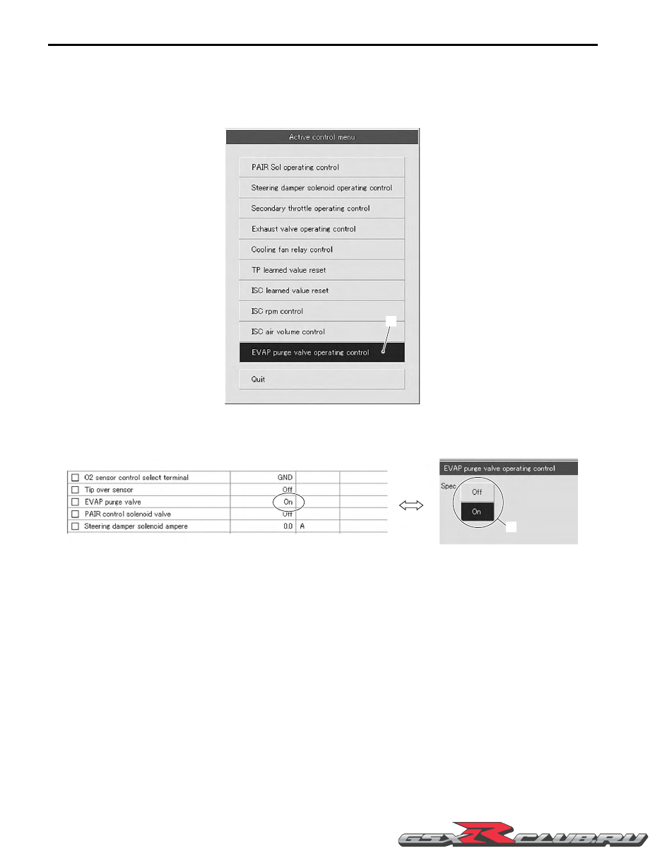
Active Control Inspection
1) Set up the SDS tool. (Refer to SDS operation manual for further details.)
2) Turn the ignition switch ON.
3) Click “EVAP purge valve operating control” (1).
4) Click each button (2). At this time, if an operating sound is heard from the EVAP system purge control valve, the
function is normal.
1
I947H1110139-01
2
I947H1110140-01