SINUMERIK 840D sl/828D. Job Planning. Programming Manual (2010-2018) - page 22
Axis couplings
9.5 Synchronous spindle
Deactivate coupling COUPOF
COUPOF can be used to define the turn-off behavior of the coupling:
● Deactivation of coupling with immediate block change:
- COUPOF(S2,S1) (with specification of leading spindle)
- COUPOF(S2) (without specification of leading spindle)
● Deactivation of coupling after switch-off positions have been crossed. The block change
takes place after the switch-off positions have been crossed.
- COUPOF(S2,S1,150) (switch-off position FS: 150°)
- COUPOF(S2,S1,150,30) (switch-off position FS: 150°, LS: 30°)
Deactivate coupling with following spindle stop COUPOFS
COUPOFS can be used to define the turn-off behavior of the coupling with following spindle
stop:
● Deactivation of coupling with following spindle stop and immediate block change:
- COUPOFS(S2,S1) (with specification of leading spindle)
- COUPOFS(S2) (without specification of leading spindle)
● Deactivation of coupling after switch-off positions have been crossed with following
spindle stop. The block change takes place after the switch-off positions have been
crossed.
- COUPOFS(S2,S1,150) (switch-off position FS: 150°)
Delete couplings COUPDEL
COUPDEL deletes the coupling:
● COUPDEL(S2,S1) (with specification of leading spindle)
● COUPDEL(S2) (without specification of leading spindle)
Reset coupling parameters, COUPRES
COUPRES activates the coupling values parameterized in the machine and setting data:
● COUPRES(S2,S1) (with specification of leading spindle)
● COUPRES(S2) (without specification of leading spindle)
Job Planning
544
Programming Manual, 03/2010, 6FC5398-2BP20-1BA0

Axis couplings
9.5 Synchronous spindle
System variables
Current coupling status of following spindle
The current coupling status of a following spindle can be read using the following system
variable:
$AA_COUP_ACT[<FS>]
Value
Meaning
0
No coupling active
4
Synchronous spindle coupling active
Note
Other system variable values refer to the axis operation.
Reference:
List Manual, System Variables
Current angular offset
The current angular offset of a following spindle in relation to the leading spindle can be read
using the following system variable:
● $AA_COUP_OFFS[<FS>] (angular offset on the setpoint side)
● $VA_COUP_OFFS[<FS>] (angular offset on the actual value side)
Note
When the controller has been disabled and subsequently re-enabled during active
coupling and follow-up mode, the position offset when the controller is re-enabled is
different to the original programmed value. In this case, the new position offset can be
read and, if necessary, corrected in the part program.
Job Planning
Programming Manual, 03/2010, 6FC5398-2BP20-1BA0
545
Axis couplings
9.6 Master/slave group (MASLDEF, MASLDEL, MASLON, MASLOF, MASLOFS)
9.6
Master/slave group (MASLDEF, MASLDEL, MASLON, MASLOF,
MASLOFS)
Function
The master/slave coupling in SW 6.4 and lower permitted coupling of the slave axes to their
master axis only while the axes involved are stopped.
Extension of SW 6.5 permits coupling and uncoupling of rotating, speed-controlled spindles
and dynamic configuration.
Syntax
MASLON(Slv1,Slv2,..., )
MASLOF(Slv1,Slv2,..., )
MASLDEF(Slv1,Slv2,..., master axis)
Extension for dynamic configuration
MASLDEL(Slv1,Slv2,..., )
Extension for dynamic configuring
extension
MASLOFS(Slv1, Slv2, ..., )
Extension for slave spindle
Note
For MASLOF/MASLOFS, the implicit preprocessing stop is not required. Because of the missing
preprocessing stop, the $P system variables for the slave axes do not provide updated
values until next programming.
Significance
General
MASLON
Close (switch-in) a temporary coupling.
MASLOF
Open an active coupling. The extensions for spindles must be
observed.
Dynamic configuration extension
MASLDEF
Coupling user-defined using machine data or also
create/change from the part program.
MASLOFS
Open the coupling analog to MASLOF and automatically brake the
slave spindle.
Job Planning
546
Programming Manual, 03/2010, 6FC5398-2BP20-1BA0
Axis couplings
9.6 Master/slave group (MASLDEF, MASLDEL, MASLON, MASLOF, MASLOFS)
MASLDEL
Uncouple master/slave axis group and delete group definition.
Slv1, Slv2, ...
Slave axes led by a master axis.
Master axis
Axis, that controls defined slave axes in a master/slave group.
Examples
Example 1: Dynamic configuration of a master/slave coupling
Dynamic configuration of a master/slave coupling from the part program:
The axis relevant after axis container rotation must become the master axis.
Program code
Comments
MASLDEF(AUX,S3)
; S3 master for AUX
MASLON(AUX)
; Close coupling for AUX
M3=3 S3=4000
; Clockwise direction of rotation
MASLDEL(AUX)
; Delete configuration and open the coupling
AXCTSWE(CT1)
; Container rotation
Examples
Example 2: Actual-value coupling of a slave axis
Actual value coupling of a slave axis to the same value of the master axis using PRESETON.
For a permanent master/slave coupling, the actual value at the SLAVE axis is to be changed
using PRESETON.
Program code
Comments
N37262 $MA_MS_COUPLING_ALWAYS_ACTIVE[AX2]=0
; Briefly switch-out the
permanent coupling.
N37263 NEWCONF
N37264 STOPRE
MASLOF(Y1)
; Temporary coupling open.
N5 PRESETON(Y1,0,Z1,0,B1,0,C1,0,U1,0)
; Set the actual value of
the non-referenced slave
axes as these are
activated with power on.
N37262 $MA_MS_COUPLING_ALWAYS_ACTIVE[AX2]=1
; Activate permanent
coupling.
N37263 NEWCONF
Job Planning
Programming Manual, 03/2010, 6FC5398-2BP20-1BA0
547
Axis couplings
9.6 Master/slave group (MASLDEF, MASLDEL, MASLON, MASLOF, MASLOFS)
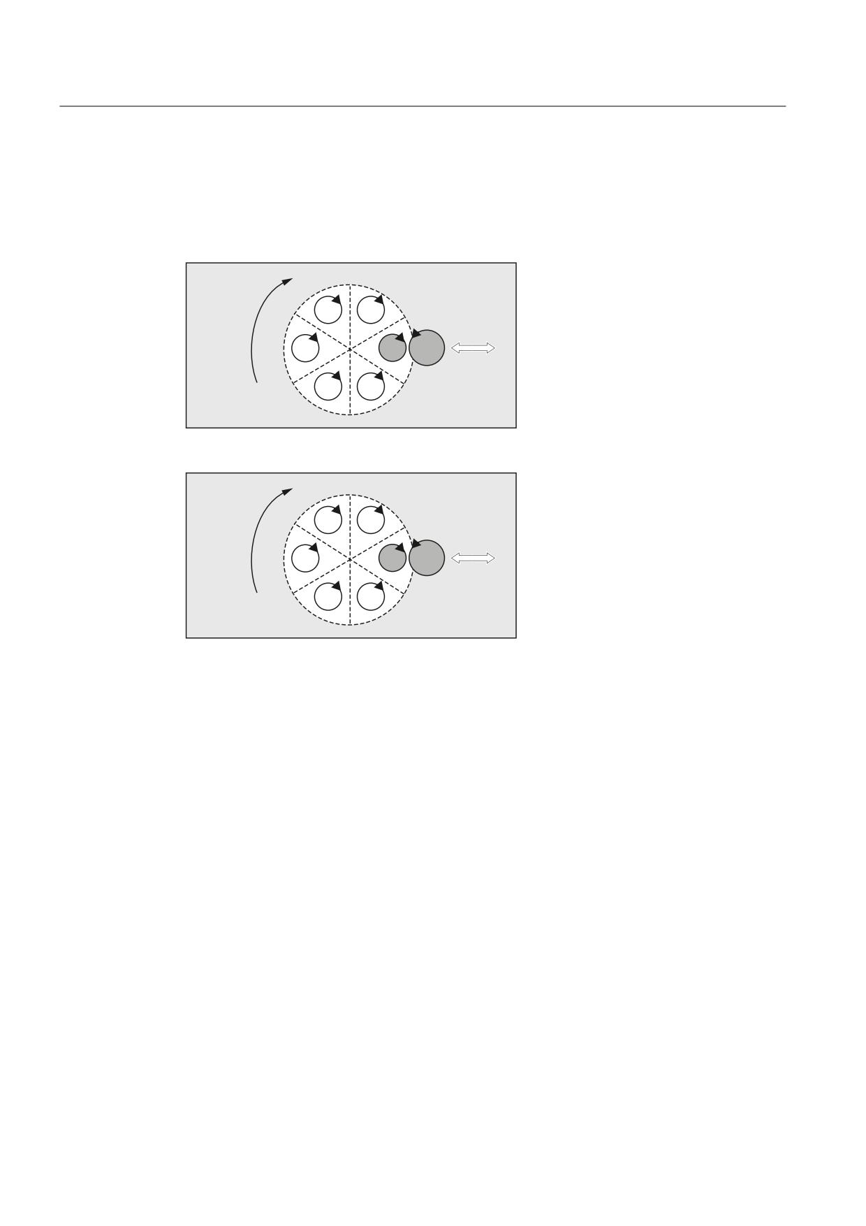
Example 3: Coupling sequence, position 3/container CT1
To enable coupling with another spindle after container rotation, the previous coupling must
be uncoupled, the configuration cleared, and a new coupling configured.
Initial situation:
6
6
'LUHFWLRQ RI
URWDWLRQ
$;
$;
0HFKDQLFDO
FRQWDLQHU
LQIHHG
6
$;
$;
$8;
$;
$;
6
6
After rotation by one slot:
6
6
'LUHFWLRQ RI
URWDWLRQ
$;
$;
0HFKDQLFDO
FRQWDLQHU
LQIHHG
6
$;
$;
$8;
$;
$;
6
6
References:
Function Manual, Extension Functions; Several Operator Panel Fronts and NCUs (B3),
Chapter "Axis container"
Job Planning
548
Programming Manual, 03/2010, 6FC5398-2BP20-1BA0
Axis couplings
9.6 Master/slave group (MASLDEF, MASLDEL, MASLON, MASLOF, MASLOFS)
Further Information
General
MASLOF
This instruction is executed directly for spindles in speed control mode.
The slave spindles rotating at this instant keep their speeds until a new
speed is programmed.
Dynamic configuration extension
MASLDEF
Definition of a master/slave group from the part program. Beforehand, the
definition was made exclusively using machine data.
MASLDEL
The instruction cancels assignment of the slave axes to the master axis
and simultaneously opens the coupling, like MASLOF.
The master/slave definitions specified in the machine data are kept.
MASLOFS
MASLOFS can be used to automatically brake slave spindles when the
coupling is opened.
For axes and spindles in the positioning mode, the coupling is only closed
and opened at standstill (zero speed).
Note
For the slave axis, the actual value can be synchronized to the same value of the master
axis using PRESETON. To do this, the permanent/slave coupling must be briefly switched-out in
order to set the actual value of the non-referenced slave axis to the value of the master/axis
with power on. Then the coupling is permanently re-established.
The permanent master/slave coupling is activated using the MD setting
MD37262 $MA_MS_COUPLING_ALWAYS_ACTIVE = 1 - and this has no effect on the
language commands of the temporary coupling.
Coupling behavior for spindles!
For spindles in the open-loop speed controlled mode, the coupling behavior of MASLON,
MASLOF, MASLOFS and MASLDEL are explicitly defined using machine data
MD37263 $MA_MS_SPIND_COUPLING_MODE.
For the default setting with MD37263 = 0, the slave axes are coupled-in and coupled-out
only when the axes involved are at standstill. MASLOFS corresponds to MASLOF.
For MD37263 = 1, the coupling instruction is immediately executed and therefore also the
motion. For MASLON the coupling is immediately closed and for MASLOFS or MASLOF immediately
opened. The slave spindles rotating at this instant in time are for MASLOFS automatically
braked and for MASLOF keep their speed until a new speed is programmed.
Job Planning
Programming Manual, 03/2010, 6FC5398-2BP20-1BA0
549
Axis couplings
9.6 Master/slave group (MASLDEF, MASLDEL, MASLON, MASLOF, MASLOFS)
Job Planning
550
Programming Manual, 03/2010, 6FC5398-2BP20-1BA0
Motion synchronous actions
10
10.1
Basics
Function
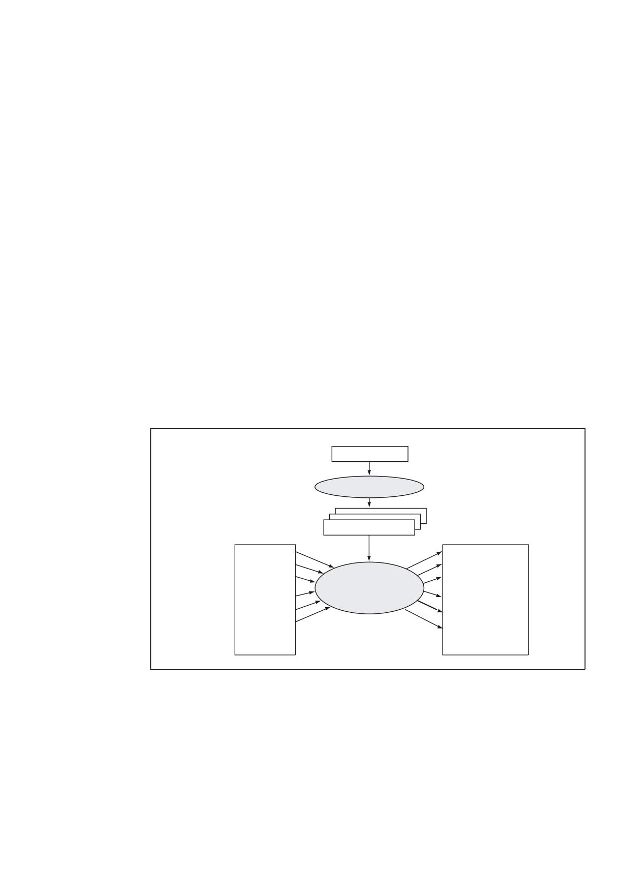
Synchronized actions allow actions to be executed such that they are synchronized to
machining blocks.
The time at which the actions are executed can be defined by conditions. The conditions are
monitored in the interpolation cycle. The actions are therefore responses to real-time events,
their execution is not limited by block boundaries.
A synchronized action also contains information about its service life and about the
frequency with which the programmed main run variables are scanned and therefore about
the frequency with which the actions are started. In this way, an action can be triggered just
once or cyclically in interpolation cycles.
Possible applications
3DUW SURJUDP
%ORFN SUHSDUDWLRQ
3UHSDUHG EORFNV
&RQGLWLRQV
$FWLRQV
1&. LQSXWV
1&. RXWSXWV
6HWSRLQWV
3RVLWLRQV
$FWXDO YDOXHV
6SHHGV
5HDO WLPH SURFHVVLQJ
3RO\QRPLDO
6\QFKURQL]HG DFWLRQV
FRHIILFLHQWV
*DWLQJ ORJLF
1& IXQFWLRQV
3DUDPHWHU
0HDVXULQJ
$FWLYDWH FRXSOLQJ
0DUNHU
6HUYR YDOXHV
0 + IXQFWLRQ LVVXHG
3RO\QRPLDO F FKDQJHG
● Optimizing runtime-critical applications (e.g. a tool change)
● Fast response to an external event
● Programming AC controls
● Setting up safety functions
●
Job Planning
Programming Manual, 03/2010, 6FC5398-2BP20-1BA0
551
Motion synchronous actions
10.1 Basics
Programming
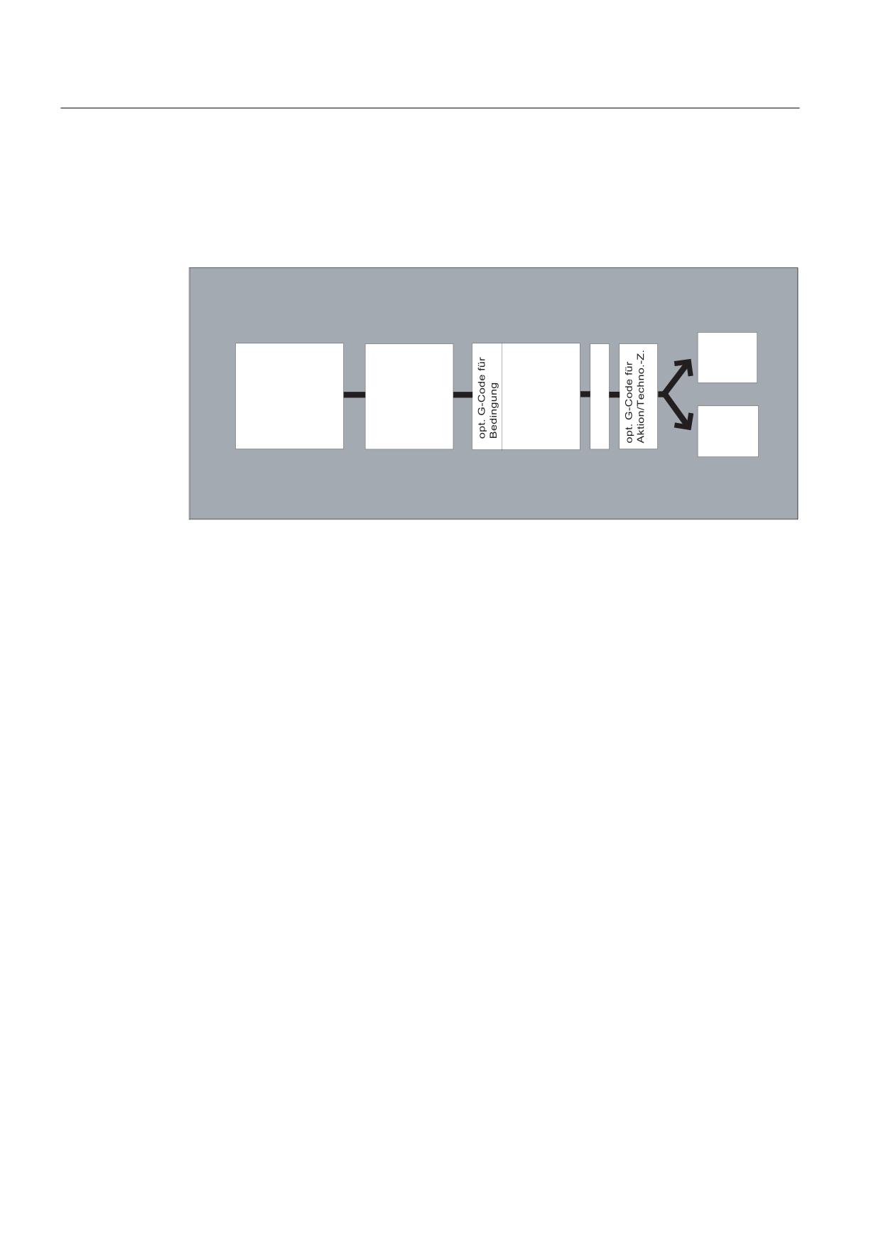
A synchronized action is programmed on its own in a separate block and triggers a machine
function as of the next executable block (e.g. traversing movement with G0, G1, G2, G3).
Synchronized actions comprise up to 5 command elements with different tasks:
$NWLRQ
,' 1XPPHU
6FKO¾VVHOZRUW
%HGLQJXQJ
'2
*¾OWLJNHLWVEHUHLFK
$EIUDJHK¦XILJNHLW
7HFKQRORJLH
]\NOXV
Syntax:
DO <action1> <action2> …
<KEYWORD> <condition> DO <action1> <action2> …
ID=<n> <KEYWORD> <condition> DO <action1> <action2> …
IDS=<n> <KEYWORD> <condition> DO <action1> <action2> …
Significance:
DO
Instruction to initiate the programmed action(s)
Only effective if the <condition> is fulfilled (if programmed).
→ See "Actions"
<action1>
<action2>
Action(s) to be started
…
Examples:
• Assign variable
• Start technology cycle
<KEYWORD>
The cyclic check of the <condition> of a synchronized action is
defined using the keyword (WHEN, WHENEVER, FROM or EVERY).
→ See "Cyclic checking of the condition"
<condition>
Gating logic for main run variables
The condition is checked in the IPO clock cycle
ID=<n>
Identification number
or
IDS=<n>
The area of validity and the position within the machining
sequence is defined using the identification number.
→ See "Area of validity and machining sequence"
Job Planning
552
Programming Manual, 03/2010, 6FC5398-2BP20-1BA0
Motion synchronous actions
10.1 Basics
Coordinating synchronized actions/technology cycles
The following commands are available to coordinate synchronized actions/technology
cycles:
Command
Significance
CANCEL(<n>)
Cancel synchronized actions
→ See "Cancel synchronized actions"
LOCK(<n>)
Disable synchronized actions
UNLOCK(<n>)
Unlock synchronized actions
RESET
Reset technology cycle
Regarding LOCK, UNLOCK and RESET:
→ See "Inhibiting, enabling, resetting"
Example
Program code
Comments
WHEN $AA_IW[Q1]>5 DO M172 H510
; If the actual value of axis Q1 exceeds 5 mm,
auxiliary functions M172 and H510 are output
at the PLC interface.
10.1.1
Area of validity and machining sequence (ID, IDS)
Function
Area of validity
The area of validity of a synchronized action is defined using the identification ID or IDS:
No modal ID:
Non-modal synchronized actions in automatic mode
ID:
ID=n modal synchronized actions in the automatic mode up to the
end of program
IDS:
Static synchronized action, effective modally in every operating
mode, also beyond the end of the program
Job Planning
Programming Manual, 03/2010, 6FC5398-2BP20-1BA0
553
Motion synchronous actions
10.1 Basics
Applications
● AC loops in JOG mode
● Logic operations for Safety Integrated
● Monitoring functions, responses to machine states in all modes
Sequence of execution
Modal synchronized actions that are statically effective are processed in the interpolation
clock cycle in the sequence of their ID or IDS number (ID=<n> or IDS=<n>).
Non-modal synchronized actions (without ID number) are executed in the programmed
sequence after execution of the modal synchronized actions.
Note
Modal synchronized actions can be protected from modifications or deletions by machine
data settings (→ machinery construction OEM!).
Programming
Syntax
Significance
No modal ID
The synchronized action is only effective in the automatic mode.
It applies only to the next executable block (block with motion
statement or other machine action), is non-modal.
Example:
WHEN $A_IN[3]==TRUE DO $A_OUTA[4]=10
ID=<n> ...
The synchronized action applies modally in the following blocks and
can be deactivated by CANCEL(<n>) or can be overwritten by
programming a new synchronized action with the same ID.
The synchronized actions active in the M30 block delay the program
end.
ID synchronized actions are only effective in the automatic mode.
Value range for <n>:
1 ... 255
Example:
ID=2 EVERY $A_IN[1]==1 DO POS[X]=0
IDS=<n>
The static synchronized actions act modally in all modes. They even
remain active beyond the end of the program and can be activated
directly after Power On using an ASUB. This means that it is
possible to activate actions that should run in the NC independent of
the selected operating mode.
Value range for <n>:
1 ... 255
Example:
IDS=1 EVERY $A_IN[1]==1 DO POS[X]=100
Job Planning
554
Programming Manual, 03/2010, 6FC5398-2BP20-1BA0
Motion synchronous actions
10.1 Basics
10.1.2
Cyclically checking the condition (WHEN, WHENEVER, FROM, EVERY)
Function
A keyword is used to define cyclic checking of the condition of a synchronized action. If no
keyword is programmed, the actions of the synchronized action is performed once in every
IPO cycle.
Keywords
No keyword
Execution of the action is not subject to any condition. The
action is executed cyclically in any interpolation cycles.
WHEN
The condition is scanned in each interpolation cycle until it is
fulfilled once, whereupon the associated action is executed
once.
WHENEVER
The condition is checked in cycles in each interpolation cycle.
The associated action is executed in each interpolation cycle
while the condition is fulfilled.
FROM
The condition is checked in each interpolation cycle until it is
fulfilled once. The action is then executed while the synchronous
action is active, i.e. even if the condition is no longer fulfilled.
EVERY
The condition is scanned in each interpolation cycle. The action
is executed once when the condition is fulfilled.
Edge triggering:
the action is executed again when the condition changes from
the FALSE state to the TRUE state.
Main run variables
The variables used are evaluated in the interpolation cycle. Main run variables in
synchronized actions do not trigger a preprocessing stop.
Analysis:
If main run variables occur in a part program (e.g. actual value, position of a digital input or
output etc.), preprocessing is stopped until the previous block has been executed and the
values of the main run variables obtained.
Job Planning
Programming Manual, 03/2010, 6FC5398-2BP20-1BA0
555
Motion synchronous actions
10.1 Basics
Examples
Example 1: No keyword
Program code
Comments
DO $A_OUTA[1]=$AA_IN[X]
; Actual value output to analog output.
Example 2: WHENEVER
Program code
Comments
WHENEVER $AA_IM[X] > 10.5*SIN(45) DO …
; Comparison with an
expression calculated
during preprocessing
WHENEVER $AA_IM[X] > $AA_IM[X1] DO …
; Comparison with other main
run variable.
WHENEVER ($A_IN[1]==1) OR ($A_IN[3]==0) DO ...
; Two comparison operations
that are gated with one
another.
Example 3: EVERY
Program code
Comments
ID=1 EVERY $AA_IM[B]>75 DO POS[U]=IC(10) FA[U]=900
; Always when the actual value of axis B
exceeds the value 75 in machine
coordinates, the U axis should move
forwards by 10 with an axial feed.
Further Information
Conditions
The condition is a logical expression which can be built up in any way using Boolean
operators. Boolean expressions should always be given in brackets.
The condition is checked in the interpolation cycle.
A G code can be given before the condition. This allows defined settings to exist for the
evaluation of the condition and the action/technology cycle to be executed, independent of
the current part program status. It is necessary to separate the synchronized actions from
the program environment, because synchronized actions are required to execute their
actions at any time from a defined initial state as a result of fulfilled trigger conditions.
Applications
Definition of the systems of measurement for condition evaluation and action through G
codes G70, G71, G700, G710.
A G code specified for the condition is valid for the evaluation of the condition and for the
action if no separate G code is specified for the action.
Only one G code of the G code group may be programmed for each part of the condition.
Job Planning
556
Programming Manual, 03/2010, 6FC5398-2BP20-1BA0
Motion synchronous actions
10.1 Basics
Possible conditions
● Comparison of main run variables (analog/digital inputs/outputs, etc.)
● Boolean gating of comparison results
● Computation of real-time expressions
● Time/distance from beginning of block
● Distance from block end
● Measured values, measurement results
● Servo values
● Velocities, axis status
10.1.3
Actions (DO)
Function
In synchronized actions, you can program one or more actions. All actions programmed in a
block are active in the same interpolation cycle.
Syntax
DO <action1> <action2> ...
Significance
DO
Initiates an action or a technology cycle when the condition is satisfied.
<action>
Action started if the condition is fulfilled, e.g., assign variable, activate
axis coupling, set NCK outputs, output M, S and H functions, specify the
programmed G code, ...
The G codes can be programmed in synchronized actions for the actions/technology cycles.
The G code may specify a different G code from the condition for all actions in the block and
technology cycles. If technology cycles are contained in the action part, the G code remains
modally active for all actions until the next G code, even after the technology cycle has been
completed.
Only one G code of the G code group (G70, G71, G700, G710) may be programmed per action
section.
Example: Synchronized action with two actions
Program code
Comments
WHEN $AA_IM[Y]>=35.7 DO M135 $AC_PARAM=50
; If the condition is fulfilled, M135 is
output at the PLC and the overide is set to
50%.
Job Planning
Programming Manual, 03/2010, 6FC5398-2BP20-1BA0
557
Motion synchronous actions
10.2 Operators for conditions and actions
10.2
Operators for conditions and actions
Comparison
Variables or partial expressions can be
(==, <>, <, >, <=, >=)
compared in conditions. The result is
always of data type BOOL. All the usual
comparison operators are permissible.
Boolean operators
Variables, constants or comparisons can
(NOT, AND, OR, XOR)
be linked with each other with the usual
Boolean operators.
Bit-by-bit operators
The bit operators B_NOT, B_AND, B_OR,
(B_NOT, B_AND, B_OR, B_XOR)
B_XOR can be used.
Basic arithmetic operations
Main run variables can be linked to one
(+, -, *, /, DIV, MOD)
another or to constants by forms of basic
computation.
Mathematical functions
Mathematical functions cannot be applied
(SIN, COS, TAN, ASIN, ACOS, ABS, TRUNC,
to variables of data type REAL .
ROUND, LN, EXP, ATAN2, POT, SQRT, CTAB,
CTABINV).
Indexing
Indexing can be undertaken using main run
expressions.
Example
● Basic arithmetic operations used together
Multiplication and division are performed before addition and subtraction and bracketing of
expressions is permissible. The operators DIV and MOD are permissible for the data type
REAL.
Programming
Comments
DO $AC_PARAM[3] = $A_INA[1]-$AA_IM[Z1]
; Subtraction of two
Main run variables
WHENEVER $AA_IM[x2] < $AA_IM[x1]-1.9 DO
; Subtraction of a constant from
$A_OUT[5] = 1
variables
DO $AC_PARAM[3] = $INA[1]-4*SIN(45.7
Constant expression, calculated
$P_EP[Y])*R4
during preprocessing
● Mathematical functions
Programming
Comments
DO $AC_PARAM[3] = COS($AC_PARAM[1])
;
;
Job Planning
558
Programming Manual, 03/2010, 6FC5398-2BP20-1BA0
Motion synchronous actions
10.2 Operators for conditions and actions
● Real-time expressions
Programming
Comments
ID=1 WHENEVER ($AA_IM[Y]>30) AND
; Selecting a position window
($AA_IM[Y]<40)
DO $AA_OVR[S1]=80
ID=67 DO $A_OUT[1]=$A_IN[2] XOR $AN_MARKER[1]
; Evaluate 2 boolean signals
ID=89 DO $A_OUT[4]=$A_IN[1] OR ($AA_IM[Y]>10)
; Output the result of a
comparison
● Main run variable indexed
Programming
Comments
WHEN…DO $AC_PARAM[$AC_MARKER[1]] = 3
;
Illegal
;
$AC_PARAM[1] = $P_EP[$AC_MARKER]
;
Job Planning
Programming Manual, 03/2010, 6FC5398-2BP20-1BA0
559
Motion synchronous actions
10.3 Main run variables for synchronized actions
10.3
Main run variables for synchronized actions
10.3.1
System variables
Function
NC data can be read and written with the help of system variables. A distinction is made
between preprocessing and main run system variables. Preprocessing variables are always
executed at the preprocessing time. Main run variables always calculate their value with
reference to the current main run status.
Name
Generally, the system variable names start with a "$" character:
Preprocessing variables:
$M...
Machine data
$S...
Setting data, protection zones
$T...
Tool management data
$P...
Programmed values, preprocessing data
$C...
Cycle variables of the ISO envelope cycles
$O...
Option data
R ...
R parameters
Main run variables:
$$A...
Actual main run data
$$V...
Servo data
$R...
R parameters
A 2nd letter describes options for accessing the variable:
N...
NCK global value (generally valid value)
C...
Channel-specific value
A...
Axis-specific value
The 2nd letter is usually only used for main run variables. Preprocessing variables, such as
e.g. $P_, are usually executed without the 2nd letter.
An underscore and the subsequent variable name (usually an English designation or
abbreviation) follow the prefix ($ followed by one or two letters).
Job Planning
560
Programming Manual, 03/2010, 6FC5398-2BP20-1BA0
Motion synchronous actions
10.3 Main run variables for synchronized actions
Data types
Main run variables can feature the following data types:
INT
Integer for whole values with prefix signs
REAL
Real for rational counting
BOOL
Boolean TRUE and FALSE
CHAR
ASCII character
STRING
Character string with alpha-numerical characters
AXIS
Axis addresses and spindles
Preprocessing variables can also feature the following data types:
FRAME
Coordinate transformations
Variable arrays
System variables can be set-up as 1 to 3-dimensional arrays.
The following data types are supported: BOOL, CHAR, INT, REAL, STRING, AXIS
The data type of the indices can be either type INT or AXIS, whereby this can be sorted as
required.
STRING variables can only be set-up in 2-dimensions.
Example for array definitions:
DEF BOOL $AA_NEWVAR[x,y,2]
DEF CHAR $AC_NEWVAR[2,2,2]
DEF INT $AC_NEWVAR[2,10,3]
DEF REAL $AA_VECTOR[x,y,z]
DEF STRING $AC_NEWSTRING[3,3]
DEF AXIS $AA_NEWAX[x,3,y]
Note
3-dimensional system variables can be displayed without any restrictions if there is a OPI
variable for the system variables
Job Planning
Programming Manual, 03/2010, 6FC5398-2BP20-1BA0
561

Motion synchronous actions
10.3 Main run variables for synchronized actions
10.3.2
Implicit type conversion
Function
During value assignments and parameter transfers, variables of different data types are
assigned or transferred.
The implicit type conversion triggers an internal type conversion of values.
Possible type conversions
To
REAL
INT
BOOL
CHAR
STRING
AXIS
FRAME
from
REAL
Yes
yes*
Yes1)
-
-
-
-
INT
Yes
Yes
Yes1)
-
-
-
-
BOOL
Yes
Yes
Yes
-
-
-
-
Explanations
*
At type conversion from REAL to INT, fractional values that are >=0.5 are rounded
up, others are rounded down (cf. ROUND function).
An alarm is output if values are exceeded.
1)
Value <> 0 is equivalent to TRUE; value == 0 is equivalent to FALSE
Results
Type conversion from REAL or INTEGER to BOOL
Result BOOL = TRUE
if the REAL or INTEGER value does not equal zero
Result BOOL = FALSE
if the REAL or INTEGER value equals zero
Type conversion from BOOL to REAL or INTEGER
Result REAL TRUE
if the BOOL value = TRUE (1)
Result INTEGER = TRUE
if the BOOL value = TRUE (1)
Type conversion from BOOL to REAL or INTEGER
Result REAL FALSE)
if the BOOL value = FALSE (0)
Result INTEGER = FALSE
if the BOOL value = FALSE (0)
Job Planning
562
Programming Manual, 03/2010, 6FC5398-2BP20-1BA0
Motion synchronous actions
10.3 Main run variables for synchronized actions
Examples of implicit type conversions
Type conversion from INTEGER to BOOL
$AC_MARKER[1]=561
ID=1 WHEN $A_IN[1] == TRUE DO $A_OUT[0]=$AC_MARKER[1]
Type conversion from REAL to BOOL
R401 = 100.542
WHEN $A_IN[0] == TRUE DO $A_OUT[2]=$R401
Type conversion from BOOL to INTEGER
ID=1 WHEN $A_IN[2] == TRUE DO $AC_MARKER[4] = $A_OUT[1]]
Type conversion from BOOL to REAL
R401 = 100.542
WHEN $A_IN[3] == TRUE DO $R10 = $A_OUT[3]
10.3.3
GUD variables
GUD variables capable of synchronized actions
As well as specific system variables, predefined global synchronized-action user variables
(synchronized action GUD) can also be used in synchronized actions. The number of
synchronized action GUD items available to the user is parameterized for each specific data
type and access using the following machine data:
● MD18660 $MM_NUM_SYNACT_GUD_REAL[<x>] = <number>
● MD18661 $MM_NUM_SYNACT_GUD_INT[<x>] = <number>
● MD18662 $MM_NUM_SYNACT_GUD_BOOL[<x>] = <number>
● MD18663 $MM_NUM_SYNACT_GUD_AXIS[<x>] = <number>
● MD18664 $MM_NUM_SYNACT_GUD_CHAR[<x>] = <number>
● MD18665 $MM_NUM_SYNACT_GUD_STRING[<x>] = <number>
The index <x> is used to specify the data block (access rights) and the value <number> to
specify the number of synchronized-action GUDs for each data type (REAL, INT, etc.). A 1-
dimensional array variable with the following naming scheme is then created in the relevant
data block for each data type.: SYG_<data type><access right>[<index>]:
Job Planning
Programming Manual, 03/2010, 6FC5398-2BP20-1BA0
563

Motion synchronous actions
10.3 Main run variables for synchronized actions
Index
Data type
<x>
(MD18660 to MD18665)
Block
REAL
INT
BOOL
AXIS
CHAR
STRING
0
SGUD
SYG_RS[ i ]
SYG_IS[ i ]
SYG_BS[ i ]
SYG_AS[ i ]
SYG_CS[ i ]
SYG_SS[ i ]
1
MGUD
SYG_RM[ i ]
SYG_IM[ i ]
SYG_BM[ i ]
SYG_AM[ i ]
SYG_CM[ i ]
SYG_SM[ i ]
2
UGUD
SYG_RU[ i ]
SYG_IU[ i ]
SYG_BU[ i ]
SYG_AU[ i ]
SYG_CU[ i ]
SYG_SU[ i ]
3
GUD4
SYG_R4[ i ]
SYG_I4[ i ]
SYG_B4[ i ]
SYG_A4[ i ]
SYG_C4[ i ]
SYG_S4[ i ]
4
GUD5
SYG_R5[ i ]
SYG_I5[ i ]
SYG_B5[ i ]
SYG_A5[ i ]
SYG_C5[ i ]
SYG_S5[ i ]
5
GUD6
SYG_R6[ i ]
SYG_I6[ i ]
SYG_B6[ i ]
SYG_A6[ i ]
SYG_C6[ i ]
SYG_S6[ i ]
6
GUD7
SYG_R7[ i ]
SYG_I7[ i ]
SYG_B7[ i ]
SYG_A7[ i ]
SYG_C7[ i ]
SYG_S7[ i ]
7
GUD8
SYG_R8[ i ]
SYG_I8[ i ]
SYG_B8[ i ]
SYG_A8[ i ]
SYG_C8[ i ]
SYG_S8[ i ]
8
GUD9
SYG_R9[ i ]
SYG_I9[ i ]
SYG_B9[ i ]
SYG_A9[ i ]
SYG_C9[ i ]
SYG_S9[ i ]
Where i = 0 to (<number> - 1)
Block: _N_DEF_DIR/_N_ ... _DEF, e.g for SGUD ⇒ _N_DEF_DIR/_N_SGUD_DEF
Properties
Synchronized-action GUD have the following properties:
● Synchronized-action GUD can be read and written in synchronized actions and part
programs/cycles.
● Synchronized-action GUD can be accessed via the OPI.
● Synchronized-action GUD is displayed on the HMI user interface in the "Parameters"
operating area.
● Synchronized-action GUD can be used on the HMI in the Wizard, in the variables view
and in the variables log.
● The array size for STRING type synchronized action GUD is set to a fixed value of 32 (31
characters + \0).
● Even if no definition files have been created manually for global user data (GUD),
synchronized-action GUD defined using machine data can be read in the corresponding
GUD block from the HMI.
NOTICE
User variables (GUD, PUD, LUD) can only be defined with the same name as
synchronized-action GUD (DEF ... SYG_xy) if no synchronized-action GUD has been
parameterized with the same name (MD18660 - MD18665). These user-defined items of
GUD cannot be used in synchronized actions.
Access rights
The access rights defined in a GUD definition file remain valid and refer only to the GUD
variables defined in this GUD definition file.
Job Planning
564
Programming Manual, 03/2010, 6FC5398-2BP20-1BA0
Motion synchronous actions
10.3 Main run variables for synchronized actions
Deletion behavior
If the content of a particular GUD definition file is reactivated, the old GUD data block in the
active file system is deleted first. The configured synchronized-action GUD is also reset at
this point. This process is also possible using the HMI in the operator area "Services" >
"Define and activated user data (GUD)".
10.3.4
Default axis identifier (NO_AXIS)
Function
AXIS type variables or parameters which have not been initialized by a value can be
provided with defined default axis identifiers. Undefined axis variables are initialized with this
default value.
Non-initialized valid axis names are recognized in synchronized actions by querying the
"NO_AXIS" variable. This non-initialized axis identifier is assigned the configured default axis
identifier by machine data.
Machine manufacturer
At least one valid existing axis identifier must be defined and pre-assigned using machine
data. All existing valid axis identifiers can however be pre-assigned. Please refer to the
machine manufacturer's instructions.
Note
During definition, newly created variables are now automatically given the value saved in the
machine data for default axis names.
For additional information on a definition applicable via machine data, see:
References:
/FBSY/ Function Manual Synchronized Actions
Syntax
PROC UP(AXIS PAR1=NO_AXIS, AXIS PAR2=NO_AXIS)
IF PAR1 <>NO_AXIS...
Significance
PROC
Subprogram definition
UP
Subprogram name for recognition
PARn
Parameter n
NO_AXIS
Initialization of formula parameter with default axis identifier
Job Planning
Programming Manual, 03/2010, 6FC5398-2BP20-1BA0
565
Motion synchronous actions
10.3 Main run variables for synchronized actions
Example: Definition of axis variables in the main program
Program code
DEF AXIS AXVAR
UP( , AXVAR)
10.3.5
Synchronized action marker ($AC_MARKER[n])
Function
The array variable $AC_MARKER[n] can be read and written in synchronized actions. These
variables can either be saved in the memory of the active or passive file system.
Synchronized action variable: Data type INT
$AC_MARKER[n]
Channel-specific marker/counter, INTEGER data type
$MC_MM_NUM_AC_MARKER
Machine data for setting the number of channel-
specific markers for movement synchronized actions
n
Array index of variables 0-n
Example of reading and writing marker variables
Program code
WHEN ... DO $AC_MARKER[0] = 2
WHEN ... DO $AC_MARKER[0] = 3
WHENEVER $AC_MARKER[0] == 3 DO $AC_OVR=50
10.3.6
Synchronized action parameters ($AC_PARAM[n])
Function
The synchronized action parameter $AC_PARAM[n] is used for calculations and as
intermediate memory in synchronized actions. These variables can either be saved in the
memory of the active or passive file system.
Job Planning
566
Programming Manual, 03/2010, 6FC5398-2BP20-1BA0
Motion synchronous actions
10.3 Main run variables for synchronized actions
Synchronized action variable: Data type:REAL
These parameters exist once in each channel under the same name.
$AC_PARAM[n]
Arithmetic variable for motion synchronized actions (REAL)
$MC_MM_NUM_AC_PARAM
Machine data for setting the number of parameters for
movement synchronized actions up to a maximum of 20000.
n
Array index of parameter 0n
Example of synchronized action parameter $AC_PARAM[n]
Program code
$AC_PARAM[0]=1.5
$AC_MARKER[0]=1
ID=1 WHEN $AA_IW[X]>100 DO $AC_PARAM[1]=$AA_IW[X]
ID=2 WHEN $AA_IW[X]>100 DO $AC_MARKER[1]=$AC_MARKER[2]
10.3.7
Arithmetic parameter ($R[n])
Function
This static array variable is used for calculations in the part program and synchronized
actions.
Syntax
Programming in part program:
REAL R[n]
REAL Rn
Programming in synchronized actions:
REAL $R[n]
REAL $Rn
Arithmetic parameters
Using arithmetic parameters allows for:
● storage of values that you want to retain beyond the end of program, NC reset, and
Power On
● display of stored value in the R parameter display.
Job Planning
Programming Manual, 03/2010, 6FC5398-2BP20-1BA0
567
Motion synchronous actions
10.3 Main run variables for synchronized actions
Examples
Program code
Comments
WHEN $AA_IM[X]>=40.5 DO $R10=$AA_MM[Y]
; Using R10 in synchronized
actions.
G01 X500 Y70 F1000
STOPRE
; Preprocessing stop
IF R10>20
; Evaluation of the arithmetic
variable.
Program code
SYG_AS[2]=X
SYG_IS[1]=1
WHEN $AA_IM[SGY_AS[2]]>10 DO $R3=$AA_EG_DENOM[SYG_AS[1]], SYG_AS[2]]
WHEN $AA_IM[SGY_AS[2]]>12 DO $AA_SCTRACE[SYG_AS[2]]=1
SYG_AS[1]=X
SYG_IS[0]=1
WHEN $AA_IM[SGY_AS[1]]>10 DO $R3=$$MA_POSCTRL_GAIN[SYG_IS[0]],SYG_AS[1]]
WHEN $AA_IM[SGY_AS[1]]>10 DO $R3=$$MA_POSCTRL_GAIN[SYG_AS[1]]
WHEN $AA_IM[SGY_AS[1]]>15 DO $$MA_POSCTRL_GAIN[SYG_AS[0]], SYG_AS[1]]=$R3
10.3.8
Read and write NC machine and NC setting data
Function
It is also possible to read and write NC machine / setting data of synchronized actions. When
reading and writing machine data array elements, an index can be left out during
programming. If this happens in the part program, all of the array's elements are described
with the value when reading the first array element and when writing.
In synchronized actions, only the first element is read or written in such cases.
Definition
MD, SD with
$: Read the value at the interpretation time of the synchronized actions
$$: Read the value in the main run
Job Planning
568
Programming Manual, 03/2010, 6FC5398-2BP20-1BA0
Motion synchronous actions
10.3 Main run variables for synchronized actions
Read MD and SD values at the preprocessing time
They are addressed from within the synchronized action using the $ characters and
evaluated by the preprocessing time.
ID=2 WHENEVER $AA_IM[z]<$SA_OSCILL_REVERSE_POS2[Z]-6 DO $AA_OVR[X]=0
;Here, reversal range 2, assumed to remain static during operation, is addressed for
oscillation.
Read MD and SD values at the main run time
They are addressed from within the synchronized action using the $ characters and
evaluated by the main run time.
ID=1 WHENEVER $AA_IM[z]<$$SA_OSCILL_REVERSE_POS2[Z]-6 DO $AA_OVR[X]=0
;It is assumed here that the reverse position can be modified by a command during
the machining
Write MD and SD at the main run time
The currently set access authorization level must allow write access. The active states are
listed for all MD and SD in References: /LIS/, Lists (Book 1).
The MD and SD to be written must be addressed preceded by $$.
Example
Program code
Comments
ID=1 WHEN $AA_IW[X]>10 DO
; Changing the switching position
$$SN_SW_CAM_PLUS_POS_TAB_1[0]=20
of software cams. Note: The
switching positions must be
changed two to three
interpolation cycles before they
reach their position.
$$SN_SW_CAM_MINUS_POS_TAB_1[0]=30
Job Planning
Programming Manual, 03/2010, 6FC5398-2BP20-1BA0
569
Motion synchronous actions
10.3 Main run variables for synchronized actions
10.3.9
Timer variable ($AC_Timer[n])
Function
System variable $AC_TIMER[n] permits actions to be started after defined periods of delay.
Timer variable: Data type:REAL
$AC_TIMER[n]
Channel-specific timer of data type REAL
s
Unit in seconds
n
Index of timer variable
Setting timers
Incrementation of a timer variable is started by means of value assignment:
$AC_TIMER[n]=value
n :
Number of time variables
value:
Starting value (generally "0")
Stopping timers
Incrementation of a timer variable can be stopped by assigning a negative value:
$AC_TIMER[n]=-1
Reading timers
The current timer value can be read whether the timer variable is running or has been
stopped. After a timer variable has been stopped through the assignment of -1, the current
time value remains stored and can be read.
Example
Output of an actual value via analog output 500 ms after detection of a digital input:
Program code
Comments
WHEN $A_IN[1] == 1 DO $AC_TIMER[1]=0
; Reset and start timer
WHEN $AC_TIMER[1]>=0.5 DO $A_OUTA[3]=$AA_IM[X] $AC_TIMER[1]=-1
Job Planning
570
Programming Manual, 03/2010, 6FC5398-2BP20-1BA0

Motion synchronous actions
10.3 Main run variables for synchronized actions
10.3.10
FIFO variables ($AC_FIFO1[n] ... $AC_FIFO10[n])
Function
10 FIFO variables (circulating buffer store) are available to store associated data sequences.
Data type: REAL
Application:
● Cyclical measurement
● Pass execution
Each element can be accessed in read or write
FIFO variables
The number of available FIFO variables is defined in machine data
MD28260 $MC_NUM_AC_FIFO.
The number of values that can be written into a FIFO variable is defined using machine data
MD28264 $MC_LEN_AC_FIFO. All FIFO variables are equal in length.
The sum of all FIFO elements is only generated if bit 0 is set in
MD28266 $MC_MODE_AC_FIFO.
Indices 0 to 5 have a special significance:
Index
Significance
0
While writing:
New value is saved in the FIFO.
While reading:
The oldest element is read and removed from the FIFO.
1
Access to oldest stored element
2
Access to latest stored element
3
Sum of all FIFO elements
4
Number of elements available in FIFO.
Read and write access can be assigned to each element of the FIFO. FIFO
variables are reset by resetting the number of elements, e.g. for the first FIFO
variable: $AC_FIFO1[4]=0
5
Current write index relative to beginning of FIFO
6 to nmax
Access to nth FIFO element
Job Planning
Programming Manual, 03/2010, 6FC5398-2BP20-1BA0
571
Motion synchronous actions
10.3 Main run variables for synchronized actions
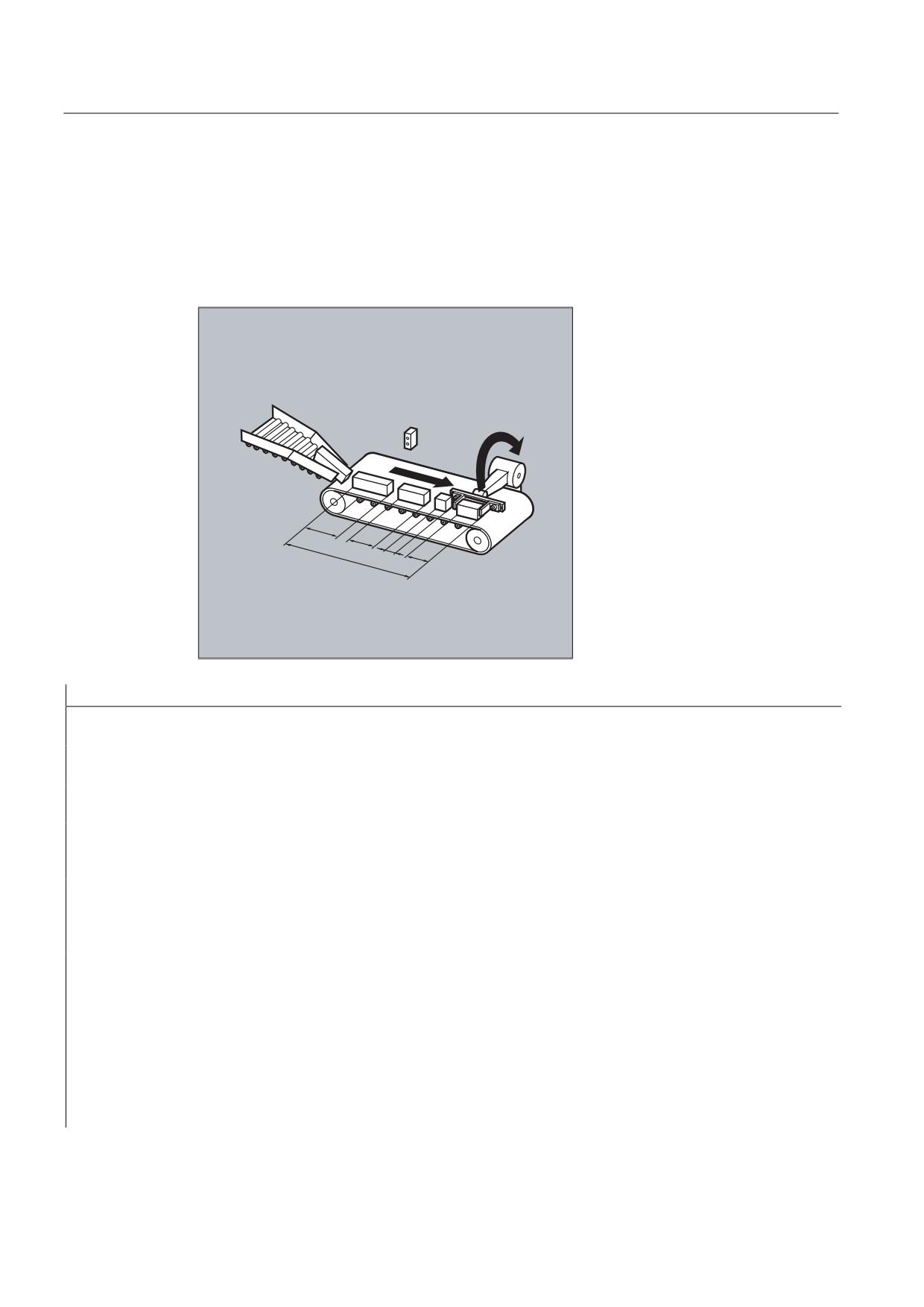
Example: Circulating memory
During a production run, a conveyor belt is used to transport products of different lengths (a,
b, c, d). The conveyor belt of transport length therefore carries a varying number of products
depending on the lengths of individual products involved in the process. With a constant
speed of transport, the function for removing the products from the belt must be adapted to
the variable arrival times of the products.
D
E
F
O
G
Program code
Comments
DEF REAL INTV=2.5
;
Constant distance between products
that are placed down.
DEF REAL TOTAL=270
;
Distance between the length
measurement and removal position.
EVERY $A_IN[1]==1 DO $AC_FIFO1[4]=0
;
At the start of the process,
reset FIFO
EVERY $A_IN[2]==1 DO $AC_TIMER[0]=0
;
If a product interrupts the light
barrier, start the time
measurement.
EVERY $A_IN[2]==0 DO $AC_FIFO1[0]=$AC_TIMER[0]*$AA_VACTM[B]
;
If the product leaves the light
barrier, calculate the product
length from the measured time and
transport speed and save in FIFO.
EVERY $AC_FIFO1[3]+$AC_FIFO1[4]*ZWI>=GESAMT DO POS[Y]=-30
;
As soon as the sum of all product
$R1=$AC_FIFO1[0]
lengths and intermediate distances
are greater than/equal to
the length between the position
where the product is placed down
and where it is removed, remove the
product from the conveyor belt at
the removal position, read-out the
associated product length from
FIFO.
Job Planning
572
Programming Manual, 03/2010, 6FC5398-2BP20-1BA0
Motion synchronous actions
10.3 Main run variables for synchronized actions
10.3.11
Information about block types in the interpolator ($AC_BLOCKTYPE,
$AC_BLOCKTYPEINFO, $AC_SPLITBLOCK)
Function
The following system variables are available for synchronized actions to provide information
about a block current executing in the main run:
● $AC_BLOCKTYPE
● $AC_BLOCKTYPEINFO
● $AC_SPLITBLOCK
Block type and block type info variables
$AC_BLOCKTYPE
$AC_BLOCKTYPEINFO
Value:
Value:
0
Not equal to 0
T
H
Z
E
Meaning:
Origi-
Intermediate block
Trigger for intermediate block:
nal block
1
1
0
0
0
Internally generated block, no further information
2
2
0
0
1
Chamfer/rounding: Straight
2
2
0
0
2
Chamfer/rounding: Circle
3
3
0
0
1
WAB: Approach with straight line
3
3
0
0
2
WAB: Approach with quadrant
3
3
0
0
3
WAB: Approach with semicircle
Tool compensation:
4
4
0
0
1
Approach block after STOPRE
4
4
0
0
2
Connection blocks if intersection point not found
4
4
0
0
3
Point-type circle on inner corners
(on TRACYL only)
4
4
0
0
4
Bypass circle (or conical cut) at outer corners
4
4
0
0
5
Approach blocks for offset suppression
4
4
0
0
6
Approach blocks on repeated TRC activation
4
4
0
0
7
Block split due to excessive curvature
4
4
0
0
8
Compensation blocks on 3D face milling (tool
vector || area vector)
Corner rounding with:
5
5
0
0
1
G641
5
5
0
0
2
G642
Job Planning
Programming Manual, 03/2010, 6FC5398-2BP20-1BA0
573
Motion synchronous actions
10.3 Main run variables for synchronized actions
$AC_BLOCKTYPE
$AC_BLOCKTYPEINFO
Value:
Value:
0
Not equal to 0
T
H
Z
E
Meaning:
Origi-
Intermediate block
Trigger for intermediate block:
nal block
5
5
0
0
3
G643
5
5
0
0
4
G644
TLIFT block with:
6
6
0
0
1
linear movement of tangential axis and without lift
motion
6
6
0
0
2
nonlinear movement of tangential axis
(polynomial) and without lift motion
6
6
0
0
3
lift movement, tangential axis movement and lift
movement start simultaneously
6
6
0
0
4
lift movement, tangential axis does not start until
certain lift position is reached.
Path segmentation:
7
7
0
0
1
programmed path segmentation is active without
punching or nibbling
7
7
0
0
2
programmed path segmentation with active
punching or nibbling
7
7
0
0
3
automatically, internally generated path
segmentation
Compile cycles:
8
ID application
ID of the compile cycle application that generated
the block
T: Thousands digit
H: Hundreds digit
Z: Tens digit
E: Units digit
Note
$AC_BLOCKTYPEINFO also always includes the value for the block type in the thousands
position (T) in the case that there is an intermediate block. The thousands position is not
accepted in $AC_BLOCKTYPE not equal to 0.
Job Planning
574
Programming Manual, 03/2010, 6FC5398-2BP20-1BA0
Motion synchronous actions
10.3 Main run variables for synchronized actions
$AC_SPLITBLOCK
Value:
Significance:
0
Unchanged programmed block (a block generated by the compressor is also dealt with as
a programmed block)
1
There is an internally generated block or a shortened original block
3
The last block in a chain of internally generated blocks or shortened original blocks is
available
Example: Counting blending blocks
Program code
Comments
$AC_MARKER[0]=0
$AC_MARKER[1]=0
$AC_MARKER[2]=0
; Definition of synchronized actions with which
blending blocks are counted.
; All blending blocks are counted in $AC_MARKER[0]:
ID=1 WHENEVER ($AC_TIMEC==0) AND ($AC_BLOCKTYPE==5) DO $AC_MARKER[0]=$AC_MARKER[0]+1
; Blending blocks generated with G641 are counted in $AC_MARKER[1]:
ID=2 WHENEVER ($AC_TIMEC==0) AND ($AC_BLOCKTYPEINFO==5001) DO $AC_MARKER[1]=$AC_MARKER[1]+1
; Blending blocks generated with G642 are counted in $AC_MARKER[2]:
ID=3 WHENEVER ($AC_TIMEC==0) AND ($AC_BLOCKTYPEINFO==5002) DO $AC_MARKER[2]=$AC_MARKER[2]+1
Job Planning
Programming Manual, 03/2010, 6FC5398-2BP20-1BA0
575
Motion synchronous actions
10.4 Actions in synchronized actions
10.4
Actions in synchronized actions
10.4.1
Overview of possible actions in synchronized actions
Actions in synchronized actions consist of value assignments, function or parameter calls,
keywords or technology cycles. Complex executions are possible using operators.
Possible applications include:
● Calculations of complex expressions in the IPO cycle
● Axis movements and spindle controls
● Setting data from synchronized actions can be changed and evaluated online (e.g. output
positions and times of software cams at the PLC or NC I/O)
● Output of auxiliary functions to PLC
● Set-up additional safety functions
● Set superimposed movement, online tool offset and clearance control
● Execute actions in all operating modes
● Influence synchronized actions from PLC
● Run technology cycles
● Output of digital and analog signals
● Record performance recording of the synchronized actions at the interpolation cycle and
the computation time of the position controller for the loading report
● Diagnostic capabilities in the user interface
Job Planning
576
Programming Manual, 03/2010, 6FC5398-2BP20-1BA0
Motion synchronous actions
10.4 Actions in synchronized actions
Synchronized action
Description
DO $V…=
Assign variable (servo-values)
DO $A...=
Assign variable (main-run variable)
DO $AC…[n]=
Special main run variable
DO $AC_MARKER[n]=
Read or write synchronized action markers
DO $AC_PARAM[n]=
Read or write synchronized action parameters
DO $R[n]=
Read or write arithmetic variable
DO $MD...=
Read MD value at the interpolation instant in time
DO $$SD...=
Writing SD value in the main run
DO $AC_TIMER[n]=Start value
Timers
DO $AC_FIFO1[n] …FIFO10[n]=
FIFO variables
DO $AC_BLOCKTYPE=
Interpret the current block (main run variable)
DO $AC_BLOCKTYPEINFO=
DO $AC_SPLITBLOCK=
DO M-, S and H e.g. M07
Output of M, S and H auxiliary functions
DO RDISABLE
Set read-in disable
DO STOPREOF
Cancel preprocessing stop
DO DELDTG
Fast deletion of distance-to-go without preprocessing
stop
FTCDEF(polynomial, LL, UL , coefficient)
Definition of polynomials
DO SYNFCT(Polyn., Output, Input)
Activation of synchronized functions: adaptive control
DO FTOC
Online tool offset
DO G70/G71/G700/G710
Define dimension system for positioning tasks
(dimensions either in inches or metric)
DO POS[axis]= / DO MOV[axis]=
Start/position/stop command axes
DO SPOS[spindle]=
Start/position/stop spindles
DO MOV[Axis]=value
Start/position infinite movements of a command axis
DO POS[Axis]= FA [Axis]=
Axial feed FA
ID=1 ... DO POS[axis]= FA [axis]=
Position from synchronized actions
ID=2 ... DO POS[axis]=
$AA_IM[axis] FA [axis]=
DO PRESETON(axis, value)
Set actual value (preset from synchronized actions)
ID=1 EVERY $A_IN[1]=1 DO M3 S…
Start/position/stop spindles
ID=2 EVERY $A_IN[2]=1 DO SPOS=
DO TRAILON(FA,LA,coupling factor)
Activate coupled-axis motion
DO LEADON(FA,LA,NRCTAB,OVW)
Activate leading value coupling
DO MEAWA(axis)=
Activate axial measurement
DO MEAC(axis)=
Activate continuous measurement
DO [array n, m]=SET(value, value, ...)
Initialization of array variables with value lists
DO [array n, m]=REP(value, value, ...)
Initialization of array variables with the same values
DO SETM(Marker No.)
Set wait markers
DO CLEARM(Marker No.)
Delete wait markers
DO SETAL(alarm no.)
Set cycle alarm (additional safety function)
Job Planning
Programming Manual, 03/2010, 6FC5398-2BP20-1BA0
577

Motion synchronous actions
10.4 Actions in synchronized actions
Synchronized action
Description
DO FXS[axis]=
Select travel to fixed stop
DO FXST[axis]=
Change clamping torque
DO FXSW[axis]=
Change monitoring window
DO FOCON[axis]=
Activate travel with limited torque/force (modal) FOC
DO FOCOF[axis]=
Deactivate travel with limited torque/force
(synchronized actions act on specific blocks)
ID=2 EVERY $AC_BLOCKTYPE==0 DO $R1=$AC_TANEB
The angle between the path tangent at the end of the
current block and the path tangent at the start of the
programmed following block
DO $AA_OVR=
Axial override
DO $AC_OVR=
Path override
DO $AA_PLC_OVR
of the axial override specified from the PLC
DO $AC_PLC_OVR
of the path override specified from the PLC
DO $AA_TOTAL_OVR
resulting axial override
DO $AC_TOTAL_OVR
resulting path override
$AN_IPO_ACT_LOAD=
Actual IPO computation time
$AN_IPO_MAX_LOAD=
longest IPO computation time
$AN_IPO_MIN_LOAD=
shortest IPO computation time
$AN_IPO_LOAD_PERCENT=
actual IPO computation time in the ratio to the IPO clock
cycle
$AN_SYNC_ACT_LOAD=
actual computation time for synchronized actions over
all channels
$AN_SYNC_MAX_LOAD=
longest computation time for synchronized actions over
all channels
$AN_SYNC_TO_IPO=
percentage component of the total synchronized action
DO TECCYCLE
Run technology cycle
DO LOCK(n, n, ...)
Inhibit
DO UNLOCK(n, n, ...)
Enable
DO RESET(n, n, ...)
RESET of a technology cycle
CANCEL(n, n, ...)
Delete modal synchronized actions with the designation
ID(S) in the part program
Job Planning
578
Programming Manual, 03/2010, 6FC5398-2BP20-1BA0
Motion synchronous actions
10.4 Actions in synchronized actions
10.4.2
Output of auxiliary functions
Function
Output timing
Auxiliary functions are output directly in the synchronized action at the output time of the
action. The output timing defined in the machine data for auxiliary functions is not active.
The output timing is given when the condition is fulfilled.
Example:
Switch on coolant at a specific axis position:
WHEN $AA_IM[X]>=15 DO M07 POS[X]=20 FA[X]=250
Permitted keywords in non-modal synchronized actions (no modal ID)
Auxiliary functions in non-modal synchronized actions (no modal ID) can only be
programmed with the WHEN or EVERY keywords.
Note
The following auxiliary functions are not permitted in synchronized actions:
• M0, M1, M2, M17, M30: Program stop/end (M2, M17, M30 possible for technology cycle)
• M functions for tool change set with M6 or via machine data
Example
Program code
Comments
WHEN $AA_IW[Q1]>5 DO M172 H510
; If the actual value of the Q1 axis exceeds
5 mm, output help functions M172 and H510
at the PLC.
Job Planning
Programming Manual, 03/2010, 6FC5398-2BP20-1BA0
579
Motion synchronous actions
10.4 Actions in synchronized actions
10.4.3
Set read-in disable (RDISABLE)
Function
Using RDISABLE, when the condition is fulfilled, the additional block processing is held in
the main program. Programmed synchronized motion actions are still executed, the following
blocks are still prepared.
In path control mode, an exact stop is always triggered at the beginning of the block with
RDISABLE in synchronized actions, regardless of whether RDISABLE is active or not.
Example
Start the program in interpolation cycles dependent on external inputs.
Program code
Comments
WHENEVER $A_INA[2]<7000 DO RDISABLE
; If the voltage 7V is not reached
at input 2,
program execution is stopped
(1000= 1V).
N10 G1 X10
; If the condition is fulfilled,
the read-in inhibit at the end of
N10 is effective
N20 G1 X10 Y20
Job Planning
580
Programming Manual, 03/2010, 6FC5398-2BP20-1BA0
Motion synchronous actions
10.4 Actions in synchronized actions
10.4.4
Cancel preprocessing stop (STOPREOF)
Function
In the case of an explicitly programmed preprocessing stop STOPRE or a preprocessing
stop implicitly activated by an active synchronized action, STOPREOF cancels the
preprocessing stop after the next machining block as soon as the condition is fulfilled.
Note
STOPREOF must be programmed with the keyword WHEN and non-modally (without ID
number).
Example
Fast program branch at end of block.
Program code
Comments
WHEN $AC_DTEB<5 DO STOPREOF
; If the distance to the end of the
block is less than 5 mm, withdraw
preprocessing stop.
G01 X100
; After executing linear
interpolation, the preprocessing
stop is withdrawn.
IF $A_INA[7]>500 GOTOF MARKE1=X100
; If the voltage of 5V at input 7
is exceeded, jump to label 1.
Job Planning
Programming Manual, 03/2010, 6FC5398-2BP20-1BA0
581
Motion synchronous actions
10.4 Actions in synchronized actions
10.4.5
Delete distance-to-go (DELDTG)
Function
Delete distance-to-go can be triggered for a path and for specified axes depending on a
condition.
The possibilities are:
● Fast, prepared delete distance-to-go
● Unprepared delete distance-to-go
Prepared delete distance-to-go with DELDTG permits a fast response to the triggering event
and is therefore used for time-critical applications, e.g. if
● the time between delete distance-to-go and the start of the next block must be very short.
● the condition for delete distance-to-go will very probably be fulfilled.
Note
The axis designation contained in brackets behind DELDTG is only valid for one
positioning axis.
Syntax
Delete distance-to-go for the path
DO DELDTG
Axial delete distance-to-go
DO DELDTG(axis1) DELDTG(axis2) ...
Example of fast deletion of distance-to-go path
Program code
Comments
WHEN $A_IN[1]==1 DO DELDTG
N100 G01 X100 Y100 F1000
; If the input is set, motion is
interrupted
N110 G01 X…
IF $AA_DELT>50…
Job Planning
582
Programming Manual, 03/2010, 6FC5398-2BP20-1BA0
Motion synchronous actions
10.4 Actions in synchronized actions
Example of fast axial deletion of distance-to-go
Program code
Comments
Cancelation of a positioning movement:
ID=1 WHEN $A_IN[1]==1 DO MOV[V]=3 FA[V]=700
; Start axis
WHEN $A_IN[2]==1 DO DELDTG(V)
; Delete distance-to-go, the axis
is stopped using MOV=0
Delete distance-to-go depending on the input
voltage:
WHEN $A_INA[5]>8000 DO DELDTG(X1)
; As soon as the voltage at input 5
exceeds 8V, delete distance-to-go
for axis X1.
Path motion continues.
POS[X1]=100 FA[X1]=10 G1 Z100 F1000
Further Information
At the end of a traversing block in which a prepared delete distance-to-go was triggered,
preprocess stop is activated implicitly.
Continuous path mode or positioning axis movements are therefore interrupted or stopped at
the end of the block with fast delete distance-to-go.
Note
Prepared delete distance-to-go:
• cannot be used with active tool radius correction.
• the action must only be programmed in non modal synchronized actions (without ID
number).
Job Planning
Programming Manual, 03/2010, 6FC5398-2BP20-1BA0
583
Motion synchronous actions
10.4 Actions in synchronized actions
10.4.6
Polynomial definition (FCTDEF)
Function
FCTDEF can be used to define 3rd order polynomials in the form y=a0+a1x+a2x2+a3x3. These
polynomials are used by the online tool offset (FTOC) and the evaluation function
(SYNFCT).
Syntax
FCTDEF(Polynomial No.,LLIMIT,ULIMIT,a0,a1,a2,a3)
Significance
Polynomial_No.
Number of the 3rd order polynomial
LLIMIT
Lower limit for function value
ULIMIT
Upper limit for function value
a0, a1, a2, a3
Polynomial coefficient
These values can also be accessed via system variables
$AC_FCTLL[n]
Lower limit for function value
$AC_FCTUL[n]
Upper limit for function value
$AC_FCT0[n]
a0
$AC_FCT1[n]
a1
$AC_FCT2[n]
a2
$AC_FCT3[n]
a3
Note
Writing system variables
• The system variables can be written from the part program or from a synchronized action.
When writing from part programs, program STOPRE to ensure that writing is block
synchronized.
• The $AC_FCTLL[n], $AC_FCTUL[n], $AC_FCT0[n] to $AC_FCTn[n] system variables can be
changed from synchronized actions
When writing form synchronized actions, the polynomial coefficients and function value limits
are active immediately.
Job Planning
584
Programming Manual, 03/2010, 6FC5398-2BP20-1BA0
Motion synchronous actions
10.4 Actions in synchronized actions
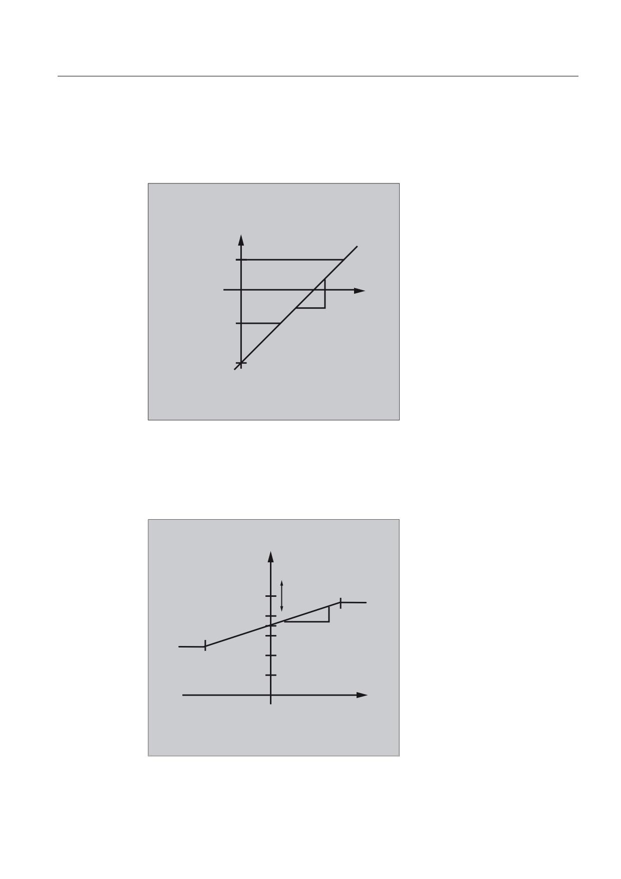
Example of a polynomial for straight section:
With upper limit 1000, lower limit -1000, ordinate section a0=$AA_IM[X] and linear gradient 1
the polynomial is:
FCTDEF(1, -1000,1000,$AA_IM[X],1)
I ;
8SSHU OLPLW
D
;
/RZHU OLPLW
D
Example of laser output control
One of the possible applications of polynomial definition is the laser output control.
Laser output control means:
Influencing the analog output in dependence on, for example, the path velocity.
$&B)&78/
>
@
(QG RI WKH EORFN
$&B)&782
>
@
(;
$&B)&7
>
@
%HJLQQLQJ RI WKH EORFN
$&B)&7//
>
@
Job Planning
Programming Manual, 03/2010, 6FC5398-2BP20-1BA0
585
Motion synchronous actions
10.4 Actions in synchronized actions
Program code
Comments
$AC_FCTLL[1]=0.2
; Definition of a polynomial
coefficients
$AC_FCTUL[1]=0.5
$AC_FCT0[1]=0.35
$AC_FCT1[1]=1.5EX-5
STOPRE
ID=1 DO $AC_FCTUL[1]=$A_INA[2]*0.1 +0.35
; Change upper limit online.
ID=2 DO SYNFCT(1,$A_OUTA[1],$AC_VACTW)
; Depending on the path velocity
(stored in $AC_VACTW) the
laser power control is controlled
via analog output 1
Note
The polynomial defined above is used with SYNFCT.
10.4.7
Synchronized function (SYNFCT)
Function
SYNFCT calculates the output value of a polynomial 3 grade weighted using the input
variables. The result is in the output variables and has maximum and minimum limits.
The evaluation function is used
● in AC control (adaptive control),
● in laser output control,
● with position feed-forward
Syntax
SYNFCT (Polynomial_No., main run variable output, main run variable input)
Job Planning
586
Programming Manual, 03/2010, 6FC5398-2BP20-1BA0
Motion synchronous actions
10.4 Actions in synchronized actions
Significance
For the output variable, it is possible to select variables that
● with additive influencing
● with multiplicative influencing
● as a position offset or
● directly
affect the machining process.
DO SYNFCT
Activation of the evaluation function
Polynomial No.
With polynomial defined with FCTDEF (see Subsection
"Polynomial definition").
Main run variable
output
Write main run variable
Main run variable input Read main run variable
Example of adaptive control (additive)
Additive influence on the programmed feedrate
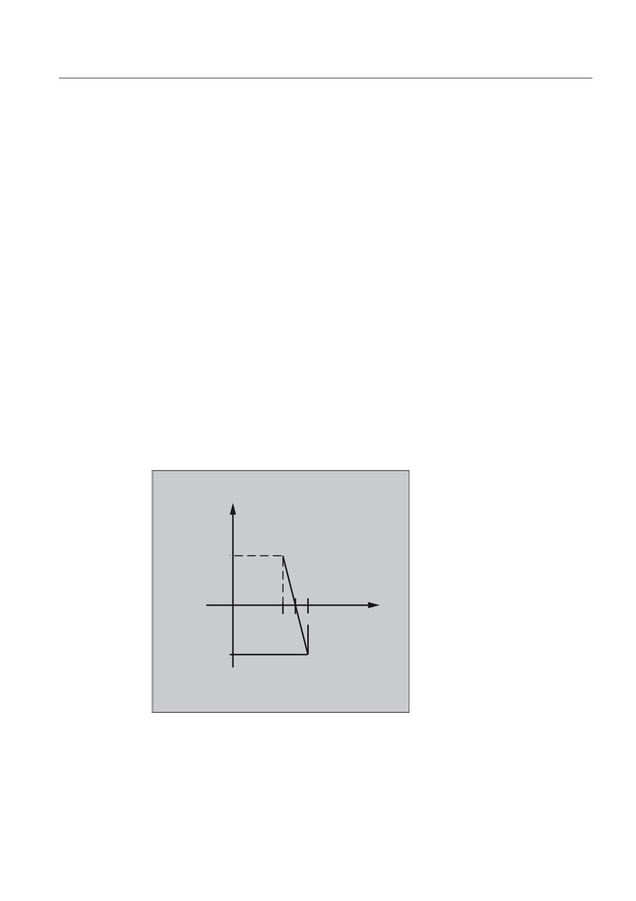
A programmed feedrate is to be controlled additive using the current of the X axis (infeed
axis):
The feedrate should only vary by +/- 100 mm/min and the current fluctuates by +/-1A around
the working point of 5A.
)
> PP PLQ @
8SSHU OLPLW
,
>$
@
/RZHU OLPLW
Job Planning
Programming Manual, 03/2010, 6FC5398-2BP20-1BA0
587
Motion synchronous actions
10.4 Actions in synchronized actions
1. Polynomial definition
Determination of the coefficients
y = f(x) = a0 + a1x + a2x2 + a3x3
a1 = -100mm/1 min A
a0 = -(-100)*5 =500
a2 = a3 = 0 (no square and cubic component)
Upper limit = 100
Lower limit = -100
This means:
FCTDEF(1,-100,100,500,-100,0,0)
2. Activate AC control
ID=1 DO SYNFCT(1,$AC_VC,$AA_LOAD[x])
;Read the current axis load (% of the max. drive current) via $AA_LOAD[x],
calculate the path feedrate override with the polynomial defined above.
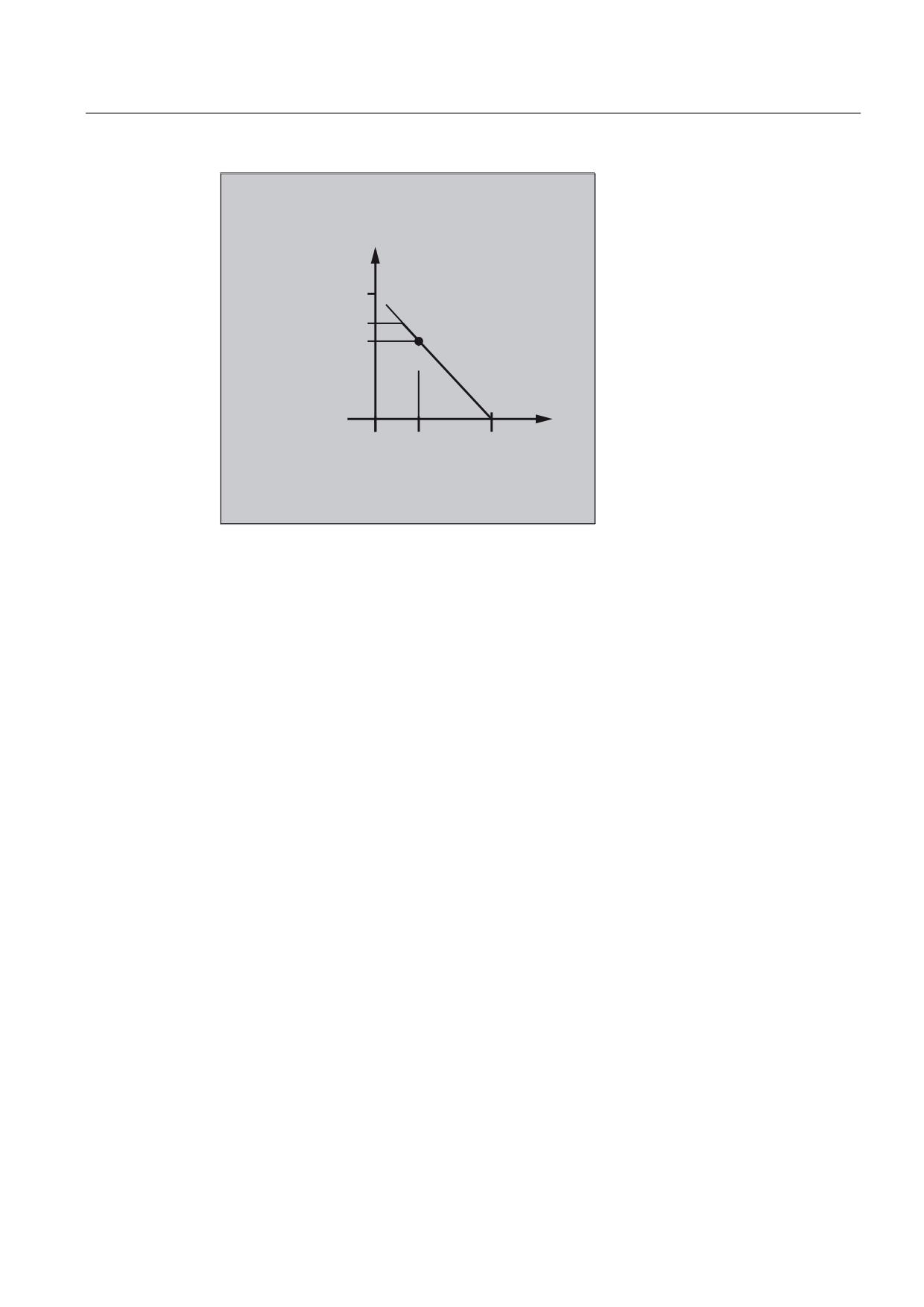
Example of adaptive control (multiplicative)
Influence the programmed feedrate by multiplication
The aim is to influence the programmed feedrate by multiplication. The feedrate must not
exceed certain limits - depending on the load on the drive:
● The feedrate is to be stopped at a drive load of 80%: override = 0
● At a drive load of 30% it is possible to traverse at programmed feedrate:
override = 100%.
The feedrate can be exceeded by 20%:
Max. override = 120%.
Job Planning
588
Programming Manual, 03/2010, 6FC5398-2BP20-1BA0
Motion synchronous actions
10.4 Actions in synchronized actions
295
>
@
8SSHU OLPLW
/RZHU OLPLW
/RDG
>
@
1. Polynomial definition
Determination of coefficients
y = f(x) = a0 + a1x +a2x2 + a3x3
a1 = -100%/(80-30)% = -2
a0 = 100 + (2*30) = 160
a2 = a3 = 0 (neither a square nor cubic element)
Upper limit = 120
Lower limit = 0
This means:
FCTDEF(2,0,120,160,-2,0,0)
2. Switch-in AC control
ID=1 DO SYNFCT(2,$AC_OVR,$AA_LOAD[x])
;Read the current axis load (% of the max. drive current) via $AA_LOAD[x],
calculate the feedrate override with the polynomial defined above.
Job Planning
Programming Manual, 03/2010, 6FC5398-2BP20-1BA0
589
Motion synchronous actions
10.4 Actions in synchronized actions
10.4.8
Closed-loop clearance control with limited correction ($AA_OFF_MODE)
Note
This function is not available for SINUMERIK 828D!
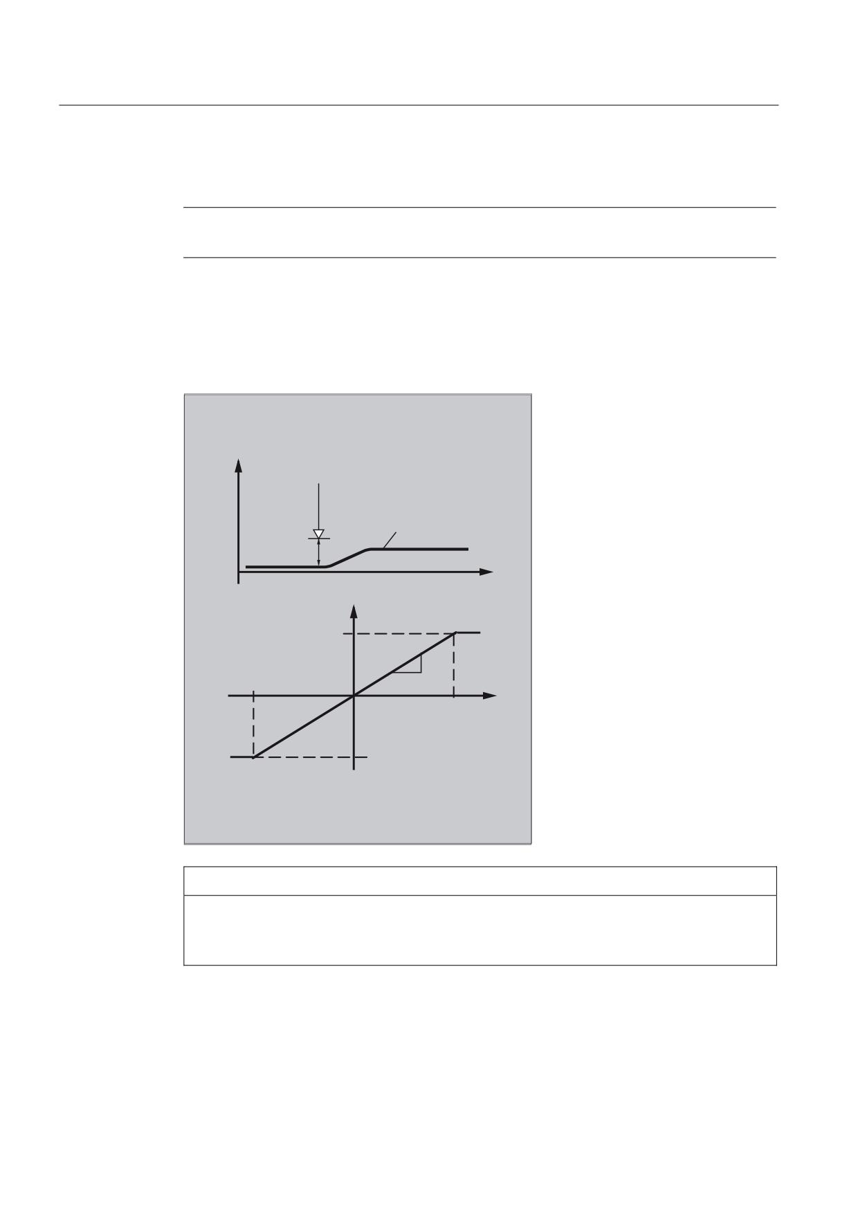
Function
The integrating calculation of the clearance values is realized with a limit range check:
$AA_OFF_MODE = 1
=
2QH GLPHQVLRQDO FOHDUDQFH FRQWURO
&OHDUDQFH
VHQVRU
H J SODWH
PP
;
2YHUODLG VSHHG
8SSHU OLPLW
P
PLQ
9
9
9
/RZHU OLPLW
NOTICE
The loop gain of the higher-level control loop depends on the setting of the interpolation
cycle.
Remedy: Read-in the MD for IPO clock cycle and take this into account.
Job Planning
590
Programming Manual, 03/2010, 6FC5398-2BP20-1BA0
Motion synchronous actions
10.4 Actions in synchronized actions
Note
Limiting of the velocity of the higher-level interpolator using MD32020 JOG_VELO for a 12
ms Ipo cycle.
Formula for the speed:
PP
P
P9
9
PV
PLQ
Example
Subprogram "AON": Clearance control on
Program code
Comment
PROC AON
$AA_OFF_LIMIT[Z]=1
; Specifies limit value.
FCTDEF(1, -10, +10, 0, 0.6, 0.12)
; Polynomial definition
ID=1 DO SYNFCT(1,$AA_OFF[Z],$A_INA[3])
; Clearance control active.
ID=2 WHENEVER $AA_OFF_LIMIT[Z]<>0
; Inhibit axis X when the limit
DO $AA_OVR[X] = 0
range is exceeded.
RET
ENDPROC
Subprogram "AOFF": Clearance control off
Program code
Comment
PROC AOFF
CANCEL(1)
; Delete synchronized action, clearance control
CANCEL(2)
; Cancel limit range check
RET
ENDPROC
Main program "MAIN"
Program code
Comment
AON
; Clearance control on
G1 X100 F1000
AOFF
; Clearance control off
M30
Job Planning
Programming Manual, 03/2010, 6FC5398-2BP20-1BA0
591
Motion synchronous actions
10.4 Actions in synchronized actions
Further Information
Position offset in the basic coordinate system
Using the system variable $AA_OFF[axis] motion can be superimposed on every axis in the
channel. It acts as a position offset in the basic coordinate system.
The position offset programmed in this way is overlaid immediately in the axis concerned,
whether the axis is being moved by the program or not.
Limit main run variable output:
It is possible to limit the absolute value to be corrected (main run variable output) to the
value saved in the setting data SD43350 $SA_AA_OFF_LIMIT.
The type of superimposition of the clearance is defined using machine data MD36750
$MA_AA_OFF_MODE:
Value
Significance
0
Proportional evaluation
1
Integrating evaluation
Using the system variable $AA_OFF_LIMIT[axis] it can be interrogated, dependent on the
direction, whether the correction value is within the limit range. The system variable can be
interrupted from synchronized actions and when a limit value is reached, can be used to e.g.
stop the axis or set an alarm.
0:
Offset value not in range
1
Limit of offset value reached in the positive direction
-1:
Limit of offset value reached in the negative direction
Job Planning
592
Programming Manual, 03/2010, 6FC5398-2BP20-1BA0
Motion synchronous actions
10.4 Actions in synchronized actions
10.4.9
Online tool offset (FTOC)
Function
FTOC permits overlaid movement for a geometry axis after a polynomial programmed with
FCTDEF depending on a reference value that might, for example, be the actual value of an
axis.
The coefficient a0 of the function definition FCTDEF(...) is evaluated for FTOC. Upper and
lower limit are dependent on a0.
FTOC can be used to program modal online tool offsets or clearance controls as synchronized
actions.
The function is used for the machining of a workpiece and dressing of a grinding wheel in the
same channel or in different channels (machining and dressing channel).
The general conditions and specifications for dressing grinding wheels apply for FTOC in the
same way that they apply for online tool offset with PUTFTOCF (see "Online tool offset
(PUTFTOCF, FCTDEF, PUTFTOC, FTOCON, FTOCOF) (Page 404)").
Syntax
FCTDEF(<function>,<LLimit>,<ULimit>,<a0>,<a1>,<a2>,<a3>)
FTOC(<function>,<reference value>,<tool parameter>,<channel>,<spindle>)
Significance
FCTDEF:
FCTDEF is used to define the polynomial function for FTOC.
Parameter:
<function>
:
Number of the polynomial function
Type: INT
Range of values:
1 to 3
<LLimit>:
Lower limit value
Type: REAL
<ULimit>:
Upper limit value
Type: REAL
<a0> to <a3>:
Coefficients of polynomial function
Type: REAL
Job Planning
Programming Manual, 03/2010, 6FC5398-2BP20-1BA0
593
Motion synchronous actions
10.4 Actions in synchronized actions
DO FTOC
:
Execute the "Continuous modal write of online tool offset" function
Parameter:
<function>
:
Number of the polynomial function
Type: INT
Range of values:
1 to 3
Note:
Must match the setting for FCTDEF.
:
Main run variable for which a function value is to be
<reference value>
calculated using the polynomial function defined with
FCTDEF.
Type: VAR REAL
<tool parameter
:
Number of the wear parameter (length 1, 2 or 3) in
which the offset value is to be added.
Type: INT
<channel>
:
Number of the channel in which the online tool offset
is to take effect.
Type: INT
Note:
A channel number only has to be specified if the
offset is not to take effect in the active channel.
<spindle>
:
Number of the spindle for which the online tool offset
is to take effect.
Type: INT
Note:
A spindle number only has to be specified if the
offset is to be applied to a non-active grinding wheel
rather than the active tool which is currently in use.
Note
FTOCON must be activated in the destination channel.
Job Planning
594
Programming Manual, 03/2010, 6FC5398-2BP20-1BA0
Motion synchronous actions
10.4 Actions in synchronized actions
Example
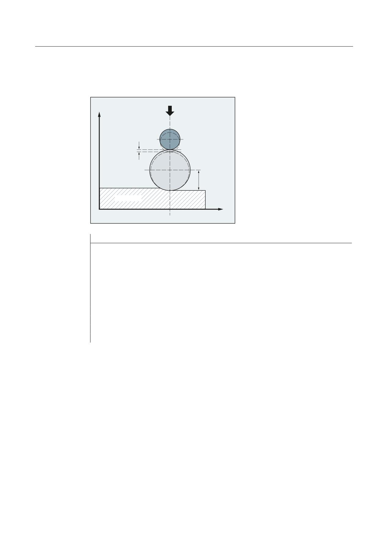
The length of the active grinding wheel is to be compensated.
<
'UHVVLQJ UROO
'UHVVLQJ
DPRXQW
*ULQGLQJ GLVF
OHQJWK
WR EH
FRUUHFWHG
:RUNSLHFH
;
Program code
Comments
FCTDEF(1,-1000,1000,-$AA_IW[V],1)
; Function definition.
ID=1 DO FTOC(1,$AA_IW[V],3,1)
; Select online tool offset: Actual value
of the V axis is the input value for
polynomial 1.Result is added in
channel 1 as compensation value to
length 3 of the active grinding disk.
WAITM(1,1,2)
; Synchronization with machining channel.
G1 V-0.05 F0.01 G91
; Feed motion to dress.
G1 V-0.05 F0.02
CANCEL(1)
; Deselect online offset.
Job Planning
Programming Manual, 03/2010, 6FC5398-2BP20-1BA0
595
Motion synchronous actions
10.4 Actions in synchronized actions
10.4.10
Online tool length compensation ($AA_TOFF)
Function
Use the system variable $AA_TOFF[ ] to overlay the effective tool lengths in accordance with
the three tool directions three-dimensionally in real time.
The three geometry axis identifiers are used as the index. This defines the number of active
directions of compensation by the geometry axes active at the same time.
All compensations can be active at the same time.
Syntax
N... TRAORI
N... TOFFON(X,<offset value>)
N... WHEN TRUE DO $AA_TOFF[X]
N... TOFFON(Y,<offset value>)
N... WHEN TRUE DO $AA_TOFF[Y]
N... TOFFON(Z,<offset value>)
N... WHEN TRUE DO $AA_TOFF[Z]
Meaning
TOFFON
:
Activate online tool length compensation
X, Y, Z:
Tool direction, in which the online tool
length compensation should be active.
<offset value>:
When activating, an offset value can be
specified for the relevant direction of
compensation and this is immediately
recovered.
TOFFOF:
Reset online tool length compensation
The compensation values in the specified compensation
direction are reset and a pre-processing stop is initiated.
$AA_TOFF[X]=<value>:
Overlay in the X direction
$AA_TOFF[Y]=<value>:
Overlay in the Y direction
$AA_TOFF[Z]=<value>:
Overlay in the Z direction
Job Planning
596
Programming Manual, 03/2010, 6FC5398-2BP20-1BA0
Motion synchronous actions
10.4 Actions in synchronized actions
Examples
Example 1: Selecting the tool length compensation
Program code
Comment
N10 TRAORI(1)
; Transformation on.
N20 TOFFON(Z)
; Activation of online tool length compensation
for the Z tool direction.
N30 WHEN TRUE DO $AA_TOFF[Z]=10 G4 F5
; A TLC of 10 is interpolated for the Z tool
direction.
N40 TOFFON(X)
; Activation of online tool length compensation
for the X tool direction.
N50 ID=1 DO $AA_TOFF[X]=$AA_IW[X2] G4 F5
; For the X tool direction compensation is
implemented depending on the position of axis
X2.
; Assigns actual compensation in the X direction.
For the X tool direction, the TLC is reduced
back to 0:
N100 XOFFSET=$AA_TOFF_VAL[X] N120 TOFFON(X,-XOFFSET) G4 F5
Example 2: Deselect the tool length compensation
Program code
Comment
N10 TRAORI(1)
; Transformation on.
N20 TOFFON(X)
; Activation of online tool length compensation
for the X tool direction.
N30 WHEN TRUE DO $AA_TOFF[X]=10 G4 F5
; A TLC of 10 is interpolated for the X tool
direction.
N80 TOFFOF(X)
; Position offset of the X tool direction is
deleted:
...$AA_TOFF[X]=0
No axis is moved.
The position offset is added to the actual
position in the WCS corresponding to the actual
orientation.
Job Planning
Programming Manual, 03/2010, 6FC5398-2BP20-1BA0
597
Motion synchronous actions
10.4 Actions in synchronized actions
10.4.11
Positioning movements
Function
Axes can be positioned completely unsynchonized with respect to the parts program from
synchronized actions. Programming positioning axes from synchronized actions is advisable
for cyclic sequences or operations that are strongly dependent on events. Axes programmed
from synchronized actions are called command axes.
Programming
References:
/PG/ Programming Manual Fundamentals; "Path details" Section
/FBSY/ Function Description, Synchronized Actions; "Starting command axes"
Parameters
The measuring system for positioning tasks in synchronized actions is specified with the G
codes G70/G71/G700/G710.
By programming the G functions in the synchronized action, the INCH/METRIC evaluation
for the synchronized action can be defined independently of the parts program context.
Job Planning
598
Programming Manual, 03/2010, 6FC5398-2BP20-1BA0
Motion synchronous actions
10.4 Actions in synchronized actions
10.4.12
Position axis (POS)
Function
Unlike programming from the part program, the positioning axis movement has no effect on
execution of the part program.
Syntax
POS[axis]=value
Significance
DO POS
Start/position command axis
Axis
Name of the axis to be traversed
Value
The value to traverse by (depending on traverse mode)
Examples
Example 1:
Program code
Comments
ID=1 EVERY $AA_IM[B]>75 DO POS[U]=100
; Axis U traverses, dependent on the traversing mode,
incrementally through 100 (inch/mm) or to position
100 (inch/mm) from the control zero.
; Traverse axis U by the distance calculated from the
main run variables:
ID=1 EVERY $AA_IM[B]>75 DO POS[U]=$AA_MW[V]-$AA_IM[W]+13.5
Example 2:
Program environment influences the positioning travel of the positioning axis
(no G function in the action component of the synchronized action):
Program code
Comments
N100 R1=0
N110 G0 X0 Z0
N120 WAITP(X)
N130 ID=1 WHENEVER $R==1 DO POS[X]=10
N140 R1=1
N150 G71 Z10 F10
; Z=10mm X=10mm
N160 G70 Z10 F10
; Z=254mm X=254mm
N170 G71 Z10 F10
; Z=10mm X=10mm
N180 M30
Job Planning
Programming Manual, 03/2010, 6FC5398-2BP20-1BA0
599
Motion synchronous actions
10.4 Actions in synchronized actions
G71 in the action component of the synchronized action clearly defines the positioning travel
of the positioning axis (metric) independent of the program environment:
Program code
Comments
N100 R1=0
N110 G0 X0 Z0
N120 WAITP(X)
N130 ID=1 WHENEVER $R==1 DO G71 POS[X]=10
N140 R1=1
N150 G71 Z10 F10
; Z=10mm X=10mm
N160 G70 Z10 F10
; Z=254mm X=10mm (X always positions to 10mm)
N170 G71 Z10 F10
; Z=10mm X=10mm
N180 M30
If axis motion is not to be started at the beginning of the block, the override for the axis can
be held at 0 from a synchronized action up to the required starting instant:
Program code
Comments
WHENEVER $A_IN[1]==0 DO $AA_OVR[W]=0 G01 X10 Y25 F750 POS[W]=1500 FA=1000
; The positioning axis is held as long as digital
input 1=0.
Job Planning
600
Programming Manual, 03/2010, 6FC5398-2BP20-1BA0
Motion synchronous actions
10.4 Actions in synchronized actions
10.4.13
Position in specified reference range (POSRANGE)
Function
The POSRANGE( ) function can be used to determine whether the current interpolated
setpoint position of an axis is in a window around a specified reference position. The position
specifications can refer to coordinates systems which can be specified.
The module offset is taken into account when interrogating the actual axis position of a
module axis.
Note
The function can only be called up from the synchronized action. If called up from the part
program, the alarm 14091 %1 block %2 is triggered, function not permitted, index: %3 with
index 5 called up.
Syntax
BOOL POSRANGE(Axis, Refpos, Winlimit,[Coord])
Significance
BOOL POSRANGE
Current position of command axis is in window of specified
reference position.
AXIS <axis>
Axis identifier of machine-, channel- or geometry axis
REAL Refpos
Reference position in Coord coordinate system
REAL Winlimit
Amount resulting in limit for position window
INT Coord
MCS is active (option). The following are possible:
0 for MCS (machine coordinates system)
1 for BCS (basic coordinates system)
2 for SZS (settable zero system)
3 for WCS (workpiece coordinate system)
Function value
Current setpoint depending on position details in specified coordinates system
Function value: TRUE
if Refpos(Coord)
- abs(Winlimit)
Function value: FALSE
≤ Actpos(Coord)
≤ Refpos(Coord) + abs(Winlimit)
otherwise
Job Planning
Programming Manual, 03/2010, 6FC5398-2BP20-1BA0
601
Motion synchronous actions
10.4 Actions in synchronized actions
10.4.14
Start/stop axis (MOV)
Function
With MOV[axis]=value it is possible to start a command axis without specifying an end
position. The axis is moved in the programmed direction until another movement is set by
another motion or positioning command or until the axis is stopped with a stop command.
Syntax
MOV[axis] = value
Significance
DO MOV
Start command axis motion
Axis
Name of the axis to be started
Value
Start command for traverse/stop motion.
The sign determines the direction of motion.
The data type for the value is INTEGER.
Value >0 (usually +1)
Positive direction
Value <0 (usually -1)
Negative direction
Value ==0
Stop axis motion
Note
If an indexing axis is stopped with MOV[Axis]=0, the axis is halted at the next indexing
position.
Example
Program code
Comments
... DO MOV[U]=0
; Axis U is stopped
Job Planning
602
Programming Manual, 03/2010, 6FC5398-2BP20-1BA0
Motion synchronous actions
10.4 Actions in synchronized actions
10.4.15
Axis replacement (RELEASE, GET)
Function
For a tool change, the corresponding command axes can be requested as an action of a
synchronized action using GET(axis). The axis type assigned to this channel and the
interpolation right thus linked to this time can be queried using the $AA_AXCHANGE_TYPE
system variable. Different processes are possible depending on the actual status and on the
channel having the current interpolation right for this axis.
Once the tool change is complete, this command axis can then be released for the channel
as an action of a synchronized action using RELEASE(axis).
Machine manufacturer
The axis concerned must be assigned to the channel via machine data. Please refer to the
machine manufacturer's specifications.
Syntax
GET(axis[,axis{,...}]) Get axis
RELEASE(axis[,axis{,...}]) Release axis
Significance
DO RELEASE
Release axis as neutral axis
DO GET
Get axis for axis replacement
Axis
Name of the axis that is to be started
Example: Program sequence for axis replacement, two channels
The Z axis has been declared in the first and second channels.
Program sequence in the first channel:
Program code
Comments
WHEN TRUE DO RELEASE(Z)
; Z axis becomes the neutral axis
WHENEVER($AA_TYP[Z]==1) DO RDISABLE
; Read-in inhibit as long as Z axis
is program axis
N110 G4 F0.1
WHEN TRUE DO GET(Z)
; Z axis again becomes the NC
program axis
WHENEVER($AA_TYP[Z]<>1) DO RDISABLE
; Read-in inhibit until Z axis is
the program axis
N120 G4 F0.1
WHEN TRUE DO RELEASE(Z)
; Z axis becomes the neutral axis
WHENEVER($AA_TYP[Z]==1) DO RDISABLE
; Read-in inhibit as long as Z axis
is the program axis
N130 G4 F0.1
;
N140 START(2)
; Start the second channel
Job Planning
Programming Manual, 03/2010, 6FC5398-2BP20-1BA0
603
Motion synchronous actions
10.4 Actions in synchronized actions
Program sequence in the second channel:
Program code
Comments
WHEN TRUE DO GET(Z)
; Move Z axis to second channel
WHENEVER($AA_TYP[Z]==0) DO RDISABLE
; Read-in disable as long as Z axis
is in other channel
N210 G4 F0.1
WHEN TRUE DO GET(Z)
; Z axis is NC program axis
WHENEVER($AA_TYP[Z]<>1) DO RDISABLE
; Read-in disable until Z axis is
program axis
N220 G4 F0.1
WHEN TRUE DO RELEASE(Z)
; Z axis in second channel is
neutral axis
WHENEVER($AA_TYP[Z]==1) DO RDISABLE
; Read-in disable as long as Z axis
is program axis
N230 G4 F0.1
N250 WAITM(10, 1, 2)
; Synchronize with channel 1
Program sequence in the first channel continues:
Program code
Comments
N150 WAIM(10, 1, 2)
; Synchronize with channel 2
WHEN TRUE DO GET(Z)
; Move Z axis to this channel
WHENEVER($AA_TYP[Z]==0) DO RDISABLE
; Read-in inhibit as long as Z axis
is in another
channel
N160 G4 F0.1
N199 WAITE(2)
N999 M30
; Wait for end of program in
channel 2
Example: Axis replacement in technology cycle
The U axis U ($MA_AUTO_GET_TYPE=2) has been declared in the first and second
channel and channel 1 currently has the interpolation right. The following technology cycle is
started in channel 2:
Program code
Comments
GET(U)
; Fetch U axis to channel
POS[U]=100
; U axis is to be moved to
position 100
The command-axis-movement line POS[U] is not executed until the U axis has been moved
to channel 2.
Job Planning
604
Programming Manual, 03/2010, 6FC5398-2BP20-1BA0
Motion synchronous actions
10.4 Actions in synchronized actions
Sequence
The axis that is requested at the time the action GET (axis) is activated can be read with
respect to axis type for an axis replacement via the system variable
($AA_AXCHANGE_TYP[<axis>]:
●
0: Axis assigned to NC program
●
1: Axis assigned to PLC or active as command axis or oscillating axis
●
2: Another channel has the interpolation right
●
3: Axis is neutral axis
●
4: Neutral axis is controlled by PLC
●
5: Another channel has the interpolation right, axis is requested for NC program
●
6: Another channel has the interpolation right, axis is requested as neutral axis
●
7: Axis active for PLC or as command or oscillating axis, axis is requested for PLC
program
●
8: Axis active for PLC or as command or oscillating axis, axis is requested as neutral axis
Boundary conditions
The axis concerned must be assigned to the channel via machine data.
An axis controlled exclusively by the PLC cannot be assigned to the NC program.
References:
/FB2/ Function Manual, Extended Functions; Positioning Axes (P2)
Using GET to request an axis from another channel
If, when the GET action is activated, another channel is authorized to write (has the
interpolation right) to the axis ($AA_AXCHANGE_TYP[<axis>] == 2), axis replacement is
used to get the axis from this channel ($AA_AXCHANGE_TYP[<axis>]==6) and assign it to
the requesting channel as soon as possible.
The axis then becomes the neutral axis ($AA_AXCHANGE_TYP[<axis>]==3).
There is no reorganize in the requesting channel.
Assignment as NC program axis with reorganize:
If an attempt to make the axis the neutral axis is already in progress when the GET action is
activated ($AA_AXCHANGE_TYP[<axis>]==6), the axis is requested for the NC program
($AA_AXCHANGE_TYP[<axis>]==5) and assigned to the NC program on the channel as
soon as possible ($AA_AXCHANGE_TYP[<axis>]==0).
Job Planning
Programming Manual, 03/2010, 6FC5398-2BP20-1BA0
605
Motion synchronous actions
10.4 Actions in synchronized actions
Axis already assigned to requested channel
Assignment as NC program axis with reorganize:
If the requested axis has already been assigned to the requesting channel at the point of
activation, and its status is that of a neutral axis (not controlled by the PLC)
($AA_AXCHANGE_TYP[<axis>]==3), it is assigned to the NC program
($AA_AXCHANGE_TYP[<axis>]==0).
Axis in neutral axis status controlled by the PLC
If the axis is in neutral axis status controlled by the PLC
($AA_AXCHANGE_TYP[<axis>]==4), the axis is requested as a neutral axis
($AA_AXCHANGE_TYP[<axis>] == 8). This locks the axis for automatic axis replacement
between channels in accordance with the value of bit 0 in MD 10722: AXCHANGE_MASK
(bit 0 == 0). This corresponds to ($AA_AXCHANGE_STAT[<axis>] == 1).
Axis is active as neutral command axis/oscillating axis or assigned to PLC
If the axis is active as the command axis/oscillating axis or assigned to the PLC for travel,
PLC axis == concurrent positioning axis, ($AA_AXCHANGE_TYP[<axis>]==1), the axis is
requested as a neutral axis ($AA_AXCHANGE_TYP[<axis>] == 8). This locks the axis for
automatic axis replacement between channels in accordance with the value of bit 0 in MD
10722: AXCHANGE_MASK (bit 0 == 0). This corresponds to
($AA_AXCHANGE_STAT[<axis>] == 1).
A new GET action will request the axis for the NC program ($AA_AXCHANGE_TYP[<axis>]
changes to == 7).
Axis already assigned to NC program
If the axis is already assigned to the NC program ($AA_AXCHANGE_TYP[<axis>]==0) or if
this assignment is requested, e.g., axis replacement triggered by NC program
($AA_AXCHANGE_TYP[<axis>]==5 or $AA_AXCHANGE_TYP[<axis>] == 7), there will be
no change in state.
Job Planning
606
Programming Manual, 03/2010, 6FC5398-2BP20-1BA0
Motion synchronous actions
10.4 Actions in synchronized actions
10.4.16
Axial feed (FA)
Function
The axial feed for command axes acts modal.
Syntax
FA[<axis>]=<value>
Example
Program code
Comments
ID=1 EVERY $AA_IM[B]>75 DO POS[U]=100 FA[U]=990
; Enter fixed feedrate value.
; Generate feedrate value from main run
variables:
ID=1 EVERY $AA_IM[B]>75 DO POS[U]=100 FA[U]=$AA_VACTM[W]+100
10.4.17
Software limit switch
Function
The working area limitation programmed with G25/G26 is taken into account for the
command axes depending on the setting data $SA_WORKAREA_PLUS_ENABLE.
Switching the working area limitation on and off with G functions WALIMON/WALIMOF in the
parts program has no effect on the command axes.
Job Planning
Programming Manual, 03/2010, 6FC5398-2BP20-1BA0
607
Motion synchronous actions
10.4 Actions in synchronized actions
10.4.18
Axis coordination
Function
Typically, an axis is either moved from the part program or as a positioning axis from a
synchronized action.
If the same axis is to be traversed alternately from the part program as a path or positioning
axis and from synchronized actions, however, a coordinated transfer takes place between
both axis movements.
If a command axis is subsequently traversed from the part program, preprocessing must be
reorganized. This, in turn, causes an interruption in the part program processing comparable
to a preprocessing stop.
Example for traversing X axis alternately from part program and from synchronized actions
Program code
Comments
N10 G01 X100 Y200 F1000
;
X axis programmed in part program
…
N20 ID=1 WHEN $A_IN[1]==1 DO
;
Start positioning from synchronized action, if ;digital input
is present
POS[X]=150 FA[X]=200
…
CANCEL(1)
;
Select synchronized action
…
N100 G01 X240 Y200 F1000
;
X becomes path axis; before motion there is a delay time due
to axis transfer, if the digital input was 1 and X was
positioned from synchronized action.
Example of changing traverse command for the same axis:
Program code
Comments
ID=1 EVERY $A_IN[1]>=1 DO POS[V]=100 FA[V]=560
; Start positioning from synchronized
action, if digital >= 1
ID=2 EVERY $A_IN[2]>=1 DO POS[V]=$AA_IM[V] FA[V]=790
; Axis tracks, the 2nd input is set, i.e.
end position and feedrate for axis V,
for two synchronized actions
simultaneously active, is tracked on-
the-fly while moving.
Job Planning
608
Programming Manual, 03/2010, 6FC5398-2BP20-1BA0
Motion synchronous actions
10.4 Actions in synchronized actions
10.4.19
Set actual values (PRESETON)
Function
When PRESETON (axis, value) is executed, the current axis position is not changed but a
new value is assigned to it.
PRESETON from synchronized actions can be programmed for
● modulo rotary axes that have been started from the part program and
● all command axes that have been started from a synchronized action
Syntax
DO PRESETON(axis, value)
Significance
DO PRESETON
Setting actual values in synchronized actions
Axis
Axis of which the control zero is to be changed
Value
The value by which the control zero is to be changed
Restrictions for axes
PRESETON cannot be programmed for axes, which are involved in a transformation.
One and the same axis can by moved from the part program and from a synchronized
action, only at different times. For this reason, delays can occur in the programming of an
axis from the part program if the same axis has been program in a synchronized action first.
If the same axis is used alternately, transfer between the two axis movements is
coordinated. Part program execution must be interrupted for that.
Example
Moving the control zero of an axis
Program code
Comments
WHEN $AA_IM[a] >= 89.5 DO PRESETON(a4,10.5)
; Shift the control zero of the
axis a through 10.5 length units
(inch or mm) in the positive
axis direction
Job Planning
Programming Manual, 03/2010, 6FC5398-2BP20-1BA0
609
Motion synchronous actions
10.4 Actions in synchronized actions
10.4.20
Spindle motions
Function
Spindles can be positioned completely unsynchronized with respect to the part program from
synchronized actions. This type of programming is advisable for cyclic sequences or
operations that are strongly dependent on events.
If conflicting commands are issued for a spindle via simultaneously active synchronized
actions, the most recent spindle command takes priority.
Example of starting/stopping/positioning spindles
Program code
Comments
ID=1 EVERY $A_IN[1]==1 DO M3 S1000
; Set the direction of rotation and
speed
ID=2 EVERY $A_IN[2]==1 DO SPOS=270
; Position spindle
Example of setting the direction and speed of rotation/ positioning the spindle
Program code
Comments
ID=1 EVERY $A_IN[1]==1 DO M3 S300
; Set the direction of rotation and
speed
ID=2 EVERY $A_IN[2]==1 DO M4 S500
; Specify a new direction of
rotation and a new speed
ID=3 EVERY $A_IN[3]==1 DO S1000
; Specify a new speed
ID=4 EVERY ($A_IN[4]==1) AND ($A_IN[1]==0) DO
; Position spindle
SPOS=0
Job Planning
610
Programming Manual, 03/2010, 6FC5398-2BP20-1BA0
Motion synchronous actions
10.4 Actions in synchronized actions
10.4.21
Coupled motion (TRAILON, TRAILOF)
Function
When the coupling is activated from the synchronized action, the leading axis can be in
motion. In this case the following axis is accelerated up to the set velocity. The position of
the leading axis at the time of synchronization of the velocity is the starting position for
coupled-axis motion. The functionality of coupled-axis motion is described in the Section
"Path traversing behavior".
Syntax
Switch-in coupled motion
DO TRAILON(following axis, leading axis, coupling factor)
Deactivate coupled-axis motion
DO TRAILOF (following axis, leading axis, leading axis 2)
Significance
Activate unsynchronized coupled motion:
... DO TRAILON(FA, LA, Kf) with:
FA: Following axis
LA: Leading axis
Kf: Coupling factor
Deactivate unsynchronized coupled motion:
... DO TRAILOF(FA, LA, LA2)
with:
FA: Following axis
LA: Leading axis, optional
... DO TRAILOF(FA)
LA2: Leading axis 2, option
All couplings to the following axis are disengaged.
Job Planning
Programming Manual, 03/2010, 6FC5398-2BP20-1BA0
611
Motion synchronous actions
10.4 Actions in synchronized actions
Example
Program code
Comments
$A_IN[1]==0 DO TRAILON(Y,V,1)
;
Activation of the 1st coupled motion group
if the digital input is 1
$A_IN[2]==0 DO TRAILON(Z,W,-1)
;
Activation of the 2nd coupled axis group
G0 Z10
;
Infeed Z and W axes in the opposite ;axis
direction
G0 Y20
;
Infeed of Y and V axes in same axis
direction
G1 Y22 V25
;
Superimpose dependent and independent
movement of coupled motion axis "V"
TRAILOF (Y,V)
;
Deactivate 1st coupled axis group
TRAILOF (Z,W)
;
Deactivate 2nd coupled axis group
Example of conflict avoidance with TRAILOF
The coupled axis is released again for access as a channel axis by invoking the TRAILOF
function for the axis. It must ensure that TRAILOF is executed before the channel requests
the axis involved. However, this is not the case in this example
…
N50 WHEN TRUE DO TRAILOF(Y,X)
N60 Y100
…
In this case, the axis is not released early enough because the non-modal synchronized
action becomes active synchronously with N60 with TRAILOF, see section, Motion-
synchronous action, "Structure, basic information".
To avoid conflict situations the following procedure should be followed:
…
N50 WHEN TRUE DO TRAILOF(Y,X)
N55 WAITP(Y)
N60 Y100
Job Planning
612
Programming Manual, 03/2010, 6FC5398-2BP20-1BA0