SINUMERIK 840D sl/828D. Job Planning. Programming Manual (2010-2018) - page 20
Tool offsets
7.4 Online tool offset (PUTFTOCF, FCTDEF, PUTFTOC, FTOCON, FTOCOF)
:
Call the "Continuous non-modal write of online tool offset" function
PUTFTOCF
Parameter:
<function>
:
Number of the polynomial function
Type: INT
Note:
Must match the setting for FCTDEF.
:
Variable reference value from which the offset is
<reference value>
to be derived (e.g. changing actual value).
Type: VAR REAL
<tool parameter:
Number of the wear parameter (length 1, 2 or 3)
in which the offset value is to be added.
Type: INT
<channel>
:
Number of the channel in which the online tool
offset is to take effect.
Type: INT
Note:
A channel number only has to be specified if the
offset is not to take effect in the active channel.
<spindle>
:
Number of the spindle for which the online tool
offset is to take effect.
Type: INT
Note:
A spindle number only has to be specified if the
offset is to be applied to a non-active grinding
wheel rather than the active tool which is
currently in use.
PUTFTOC
:
Call the "Discrete write of online tool offset" function.
Parameter:
<offset value>:
Offset value to be added in the wear parameter.
Type: REAL
<tool parameter>:
See PUTFTOCF
<channel>
:
Number of the channel in which the online tool
offset is to take effect.
Type: INT
<spindle>:
See PUTFTOCF
Job Planning
406
Programming Manual, 03/2010, 6FC5398-2BP20-1BA0
Tool offsets
7.4 Online tool offset (PUTFTOCF, FCTDEF, PUTFTOC, FTOCON, FTOCOF)
Example
Surface grinding machine with:
● Y: Infeed axis for grinding wheel
● V: Infeed axis for dressing roller
● Machining channel: Channel 1 with axes X, Z, Y
● Dressing channel: Channel 2 with axis V
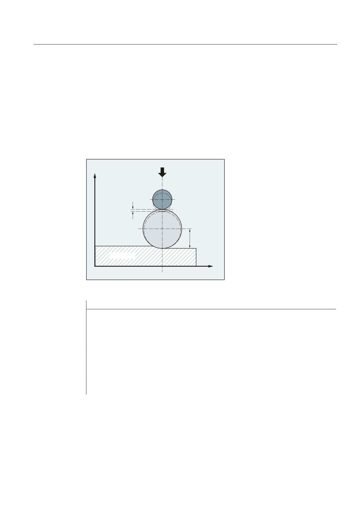
After the start of grinding motion, the grinding wheel is to be dressed by an amount of 0.05 at
X100. The dressing amount is to be applied to the grinding tool with "Write online offset
continuously".
<
'UHVVLQJ UROO
'UHVVLQJ
DPRXQW
*ULQGLQJ GLVF
OHQJWK
WR EH
FRUUHFWHG
:RUNSLHFH
;
Machining program in channel 1:
Program code
Comments
…
N110 G1 G18 F10 G90
; Basic position.
N120 T1 D1
; Select current tool.
N130 S100 M3 X100
; Spindle on, traverse to starting position.
N140 INIT(2,"DRESS","S")
; Select the dressing program in channel 2.
N150 START(2)
; Start the dressing program in channel 2.
N160 X200
; Traverse to the target point.
N170 FTOCON
; Activate online offset.
N… G1 X100
; Additional machining.
N… M30
Job Planning
Programming Manual, 03/2010, 6FC5398-2BP20-1BA0
407
Tool offsets
7.4 Online tool offset (PUTFTOCF, FCTDEF, PUTFTOC, FTOCON, FTOCOF)
Dressing program in channel 2:
Program code
Comments
…
N40 FCTDEF(1,-1000,1000,-$AA_IW[V],1)
; Define function: Straight line with
gradient = 1
N50 PUTFTOCF(1,$AA_IW[V],3,1)
; Continuously write online tool
offset: Derived from the motion of
the V axis, the length 3 of the
active grinding wheel is compensated
in channel 1.
N60 V-0.05 G1 F0.01 G91
; Infeed motion for dressing, PUTFTOCF
is only effective in this block.
…
N… M30
Further information
General information about online TO
In the case of a continuous write (for each interpolation cycle), following activation of the
evaluation function, each change is calculated additively in the wear memory (to prevent
setpoint jumps).
In both cases: The online tool offset can act on each spindle and lengths 1, 2 or 3 of the
wear parameters.
The lengths are assigned to the geometry axes with reference to the current working plane.
The spindle is assigned to the tool using tool data with GWPSON and TMON, unless this is the
active grinding wheel.
An offset is always applied for the wear parameters for the current tool side or for the left-
hand tool side on inactive tools.
Note
Where the offset is identical for several tool sides, the values should be transferred
automatically to the second tool side by means of a chaining rule.
If online offsets are defined for a machining channel, the wear values for the current tool in
this channel cannot be changed from the machining program or by means of an operator
action.
The online tool offset is also applied with respect to the constant grinding wheel peripheral
speed (GWPS) in addition to tool monitoring (TMON).
Job Planning
408
Programming Manual, 03/2010, 6FC5398-2BP20-1BA0
Tool offsets
7.5 Activate 3D tool offsets (CUT3DC..., CUT3DF...)
7.5
Activate 3D tool offsets (CUT3DC..., CUT3DF...)
7.5.1
Activating 3D tool offsets (CUT3DC, CUT3DF, CUT3DFS, CUT3DFF, ISD)
Function
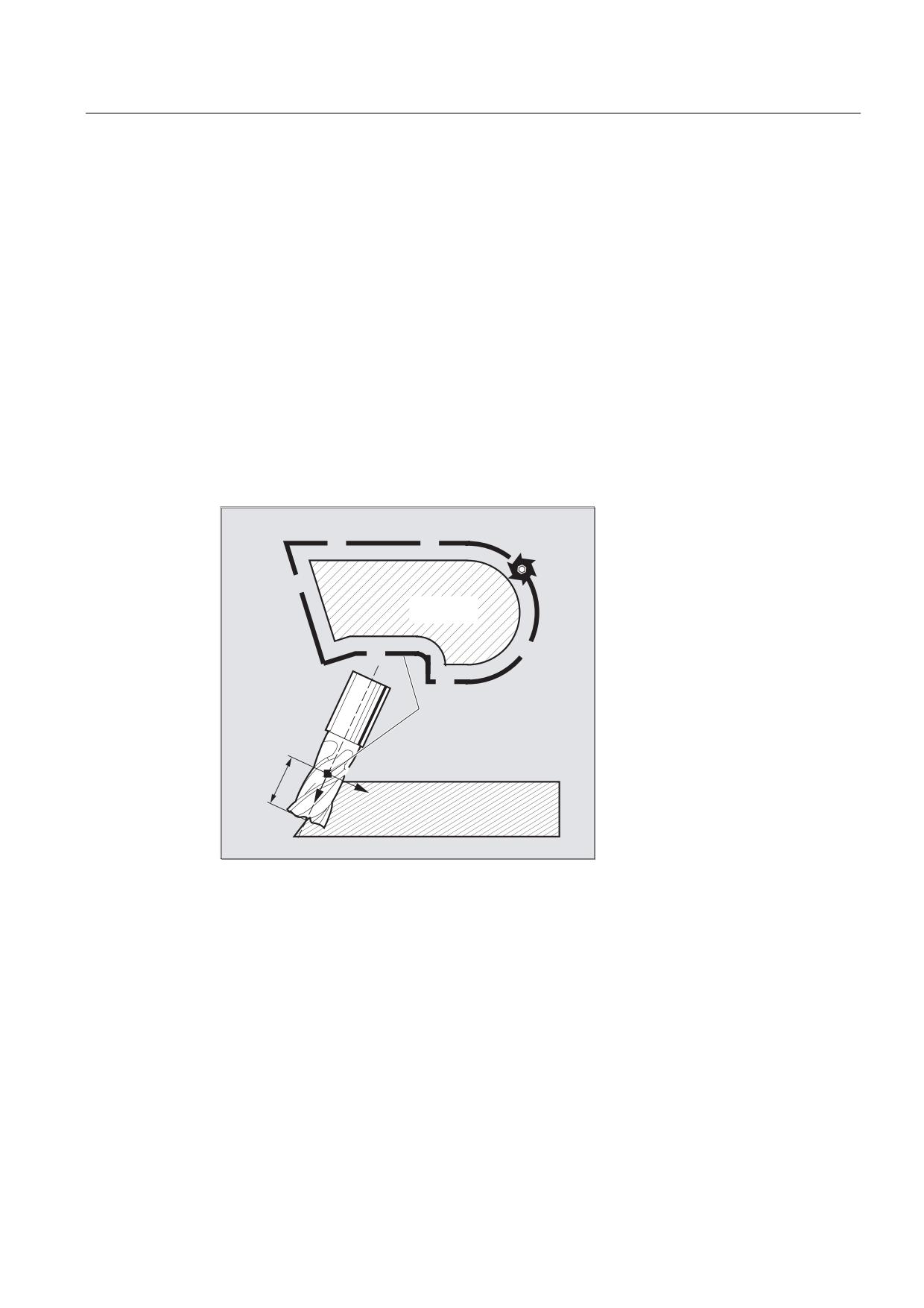
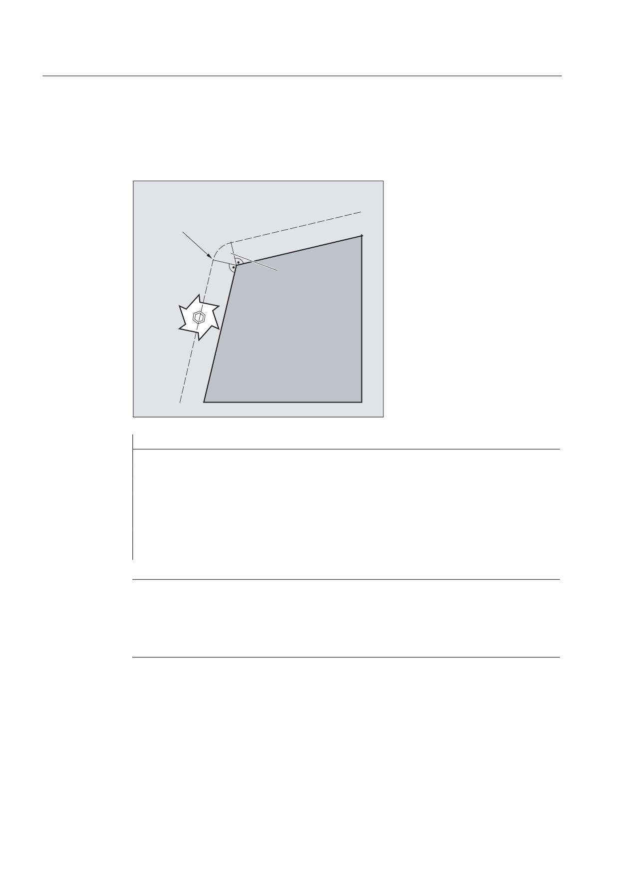
Tool orientation change is taken into account in tool radius compensation for cylindrical tools.
The same programming commands apply to 3D tool radius compensation as to 2D tool
radius compensation. The left/right offset is specified in the direction of motion using G41/G42.
The approach response is always controlled with NORM. The 3D radius compensation is only
effective when 5-axis transformation is selected.
3D tool radius compensation is also called 5D tool radius compensation, because in this
case 5 degrees of freedom are available for the orientation of the tool in space.
:RUNSLHFH
FRQWRXU
3DWK RI WKH WRRO FHQWHU LQ
WKH VDPH GLVWDQFH WR WKH
FRQWRXU HTXLGLVWDQW
,6'
/
5
Difference between 2 1/2 D and 3D tool radius compensation
In 3D tool radius compensation tool orientation can be changed. With the 2 1/2D tool radius
compensation, it is assumed that only a tool with constant orientation is being used.
Job Planning
Programming Manual, 03/2010, 6FC5398-2BP20-1BA0
409
Tool offsets
7.5 Activate 3D tool offsets (CUT3DC..., CUT3DF...)
Syntax
CUT3DC
CUT3DFS
CUT3DFF
CUT3DF
ISD=<value>
Significance
CUT3DC
Activation of 3D radius offset for circumferential milling
CUT3DFS
3D tool offset for face milling with constant orientation.
The tool orientation is determined by G17 - G19 and is not
influenced by frames.
CUT3DFF
D tool offset for face milling with constant orientation. The
tool orientation is the direction defined by G17 - G19 and, in
some case, rotated by a frame.
CUT3DF
3D tool offset for face milling with orientation change (only
with active 5-axes transformation).
G40 X... Y... Z...
To deactivate: Linear blockG0/G1 with geometry axes
ISD
Insertion depth
Note
The commands are modally effective and written in the same group asCUT2D and CUT2DF. The
command is not deselected until the next movement in the current plane is performed. This
always applies for G40 and is independent of the CUT command.
Intermediate blocks are permitted with 3D tool radius compensation. The definitions for
2 1/2D tool radius compensation apply.
Supplementary conditions
● G450/G451 and DISC
A circular block is always inserted at out corners. G450/G451 have no significance.
The DISC command is not evaluated.
Job Planning
410
Programming Manual, 03/2010, 6FC5398-2BP20-1BA0
Tool offsets
7.5 Activate 3D tool offsets (CUT3DC..., CUT3DF...)
Example
Program code
Comments
N10 A0 B0 X0 Y0 Z0 F5000
N20 T1 D1
; Tool call, call tool offset values.
N30 TRAORI(1)
; Transformation selection
N40 CUT3DC
; 3D tool radius compensation selection
N50 G42 X10 Y10
; Tool radius compensation selection
N60 X60
N70 …
7.5.2
3D tool offset peripheral milling, face milling
Circumferential milling
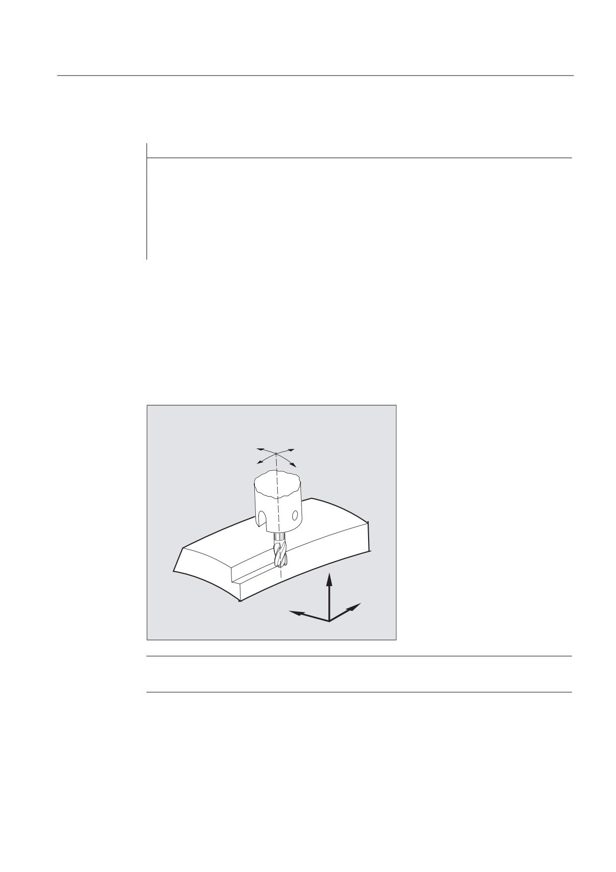
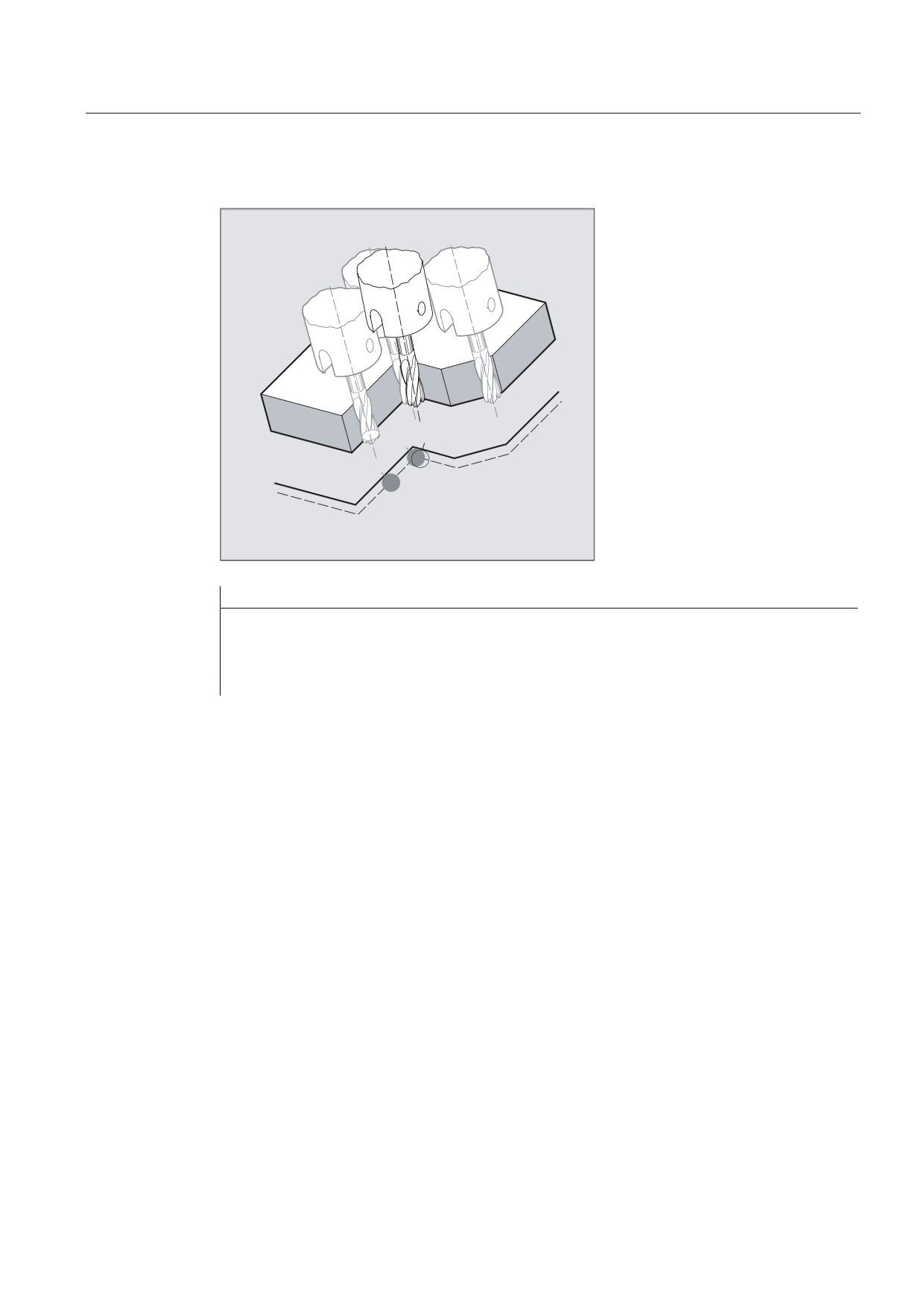
The type of milling used here is implemented by defining a path (guide line) and the
corresponding orientation. In this type of machining, the shape of the tool on the path is not
relevant. Especially the radius at the tool intervention point is decisive.
3HULSKHUDO PLOOLQJ
$
%
=
;
<
Note
The function 3D TRC is restricted to cylindrical tools.
Job Planning
Programming Manual, 03/2010, 6FC5398-2BP20-1BA0
411

Tool offsets
7.5 Activate 3D tool offsets (CUT3DC..., CUT3DF...)
Face milling
For this type of 3D milling, you will require the line-by-line description of the 3D paths on the
workpiece surface. The tool shape and dimensions are taken into account in the calculations
- which are normally performed in CAM. The post processor writes to the part program - in
addition to NC blocks - to orientations (for active 5 axis transformation) and the G code for
the required 3D tool offset. This means that the machine operator has the possibility of using
tools that are slightly smaller - deviating from the tool used to calculate the NC paths.
Example:
NC blocks were computed using a 10 mm milling tool. In this case, a milling tool diameter of
9.9 mm can be used for machining - whereby a modified roughness profile can be
expended.
Job Planning
412
Programming Manual, 03/2010, 6FC5398-2BP20-1BA0
Tool offsets
7.5 Activate 3D tool offsets (CUT3DC..., CUT3DF...)
7.5.3
3D tool offset Tool shapes and tool data for face milling
Mill shapes, tool data
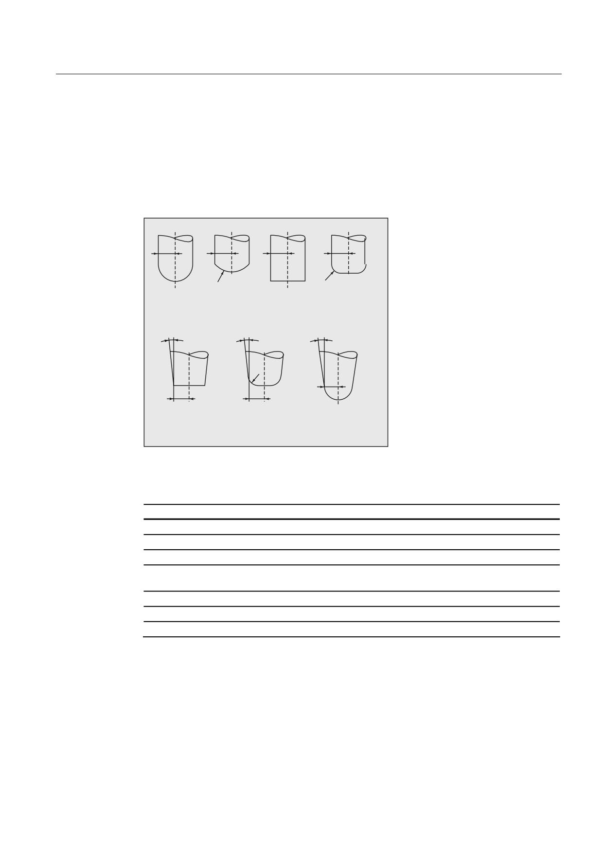
An overview of the tool shapes, which may be used for face milling operations and tool data
limit values are listed in the following. The shape of the tool shaft is not taken into account.
The effect of tool types 120 and 156 is identical.
5
5
5
5
U
U
&\OLQGULFDO
%DOO HQG
(QG PLOO
(QG PLOO ZLWK
GLH VLQNLQJ
PLOO
W\SH
FRUQHU URXQGLQJ
PLOOLQJ FXWWHU
W\SH
W\SH
W\SH
D
D
D
U
5
5
5
%HYHO FXWWHU
%HYHO FXWWHU ZLWK
7DSHUHG
W\SH
FRUQHU URXQGLQJ
GLH VLQNLQJ FXWWHU
W\SH
W\SH
If, in the NC program, a type number is specified that differs from that in the diagram, then
the system automatically uses tool type 110 (cylindrical die-sinking milling tool). An alarm is
output if the tool data limit values are violated.
Cutter type
Type No.
R
r
a
Cylindrical die-sinking milling cutter
110
> 0
-
-
Ball end mill
111
> 0
> R
-
End mill, angle head cutter
120, 130
> 0
-
-
End mill, angle head cutter with corner
121, 131
> r
> 0
-
rounding
Bevel cutter
155
> 0
-
> 0
Bevel cutter with corner rounding
156
> 0
> 0
> 0
Tapered die-sinking cutter
157
> 0
-
> 0
R
= shaft radius (tool radius)
r
= corner radius
a
= angle between the tool longitudinal axis and upper end of the torus surface
-
= is not evaluated
Job Planning
Programming Manual, 03/2010, 6FC5398-2BP20-1BA0
413

Tool offsets
7.5 Activate 3D tool offsets (CUT3DC..., CUT3DF...)
Tool data
Tool parameters
Tool dimensions
Geometry
Wear
R
$TC_DP6
$TC_DP15
r
$TC_DP7
$TC_DP16
a
$TC_DP11
$TC_DP20
Tool length offset
The tool tip is the reference point for length offset (intersection longitudinal axis/surface).
3D tool offset, tool change
A new tool with modified dimensions (R, r, a) or a different shaft may only be specified with
the programming of G41 or G42 (transition G40 to G41 or G42, reprogramming of G41 or G42).
This rule does not apply to any other tool data, e.g., tool lengths, so that tools can be loaded
without reprogramming G41 or G42.
Job Planning
414
Programming Manual, 03/2010, 6FC5398-2BP20-1BA0
Tool offsets
7.5 Activate 3D tool offsets (CUT3DC..., CUT3DF...)
7.5.4
3D tool offset Compensation on the path, path curvature, insertion depth
(CUT3DC, ISD)
Function
Compensation on path
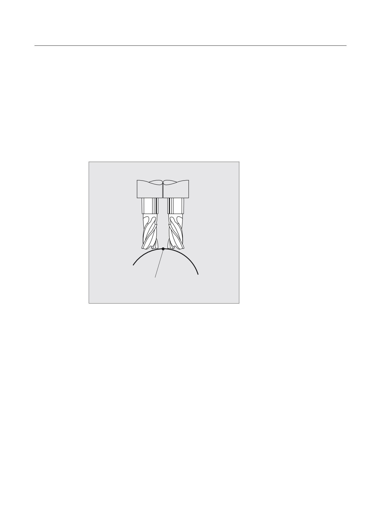
With respect to face milling, it is advisable to examine what happens when the contact point
"jumps" on the tool surface as shown in the example on the right where a convex surface is
being machined with a vertically positioned tool. The application shown in the example
should be regarded as a borderline case.
6LQJXODU SRLQW
This borderline case is monitored by the control that detects abrupt changes in the
machining point on the basis of angular approach motions between the tool and normal
surface vectors. The control inserts linear blocks at these positions so that the motion can be
executed.
These linear blocks are calculated on the basis of permissible angular ranges for the side
angle stored in the machine data. The system outputs an alarm if the limit values stored in
the machine data are violated.
Path curvature
Path curvature is not monitored. In such cases, it is also advisable to use only tools of a type
that do not violate the contour.
Insertion depth (ISD)
Insertion depth ISD is only evaluated when 3D tool radius compensation is active.
Program command ISD (insertion depth) is used to program the tool insertion depth for
circumferential milling operations. This makes it possible to change the position of the
machining point on the outer surface of the tool.
Job Planning
Programming Manual, 03/2010, 6FC5398-2BP20-1BA0
415
Tool offsets
7.5 Activate 3D tool offsets (CUT3DC..., CUT3DF...)
Syntax
3D tool compensation circumference milling
CUT3DC
ISD=<value>
Significance
CUT3DC
Activate 3D tool offset for circumferential milling, e.g., for pocket milling with
oblique side walls.
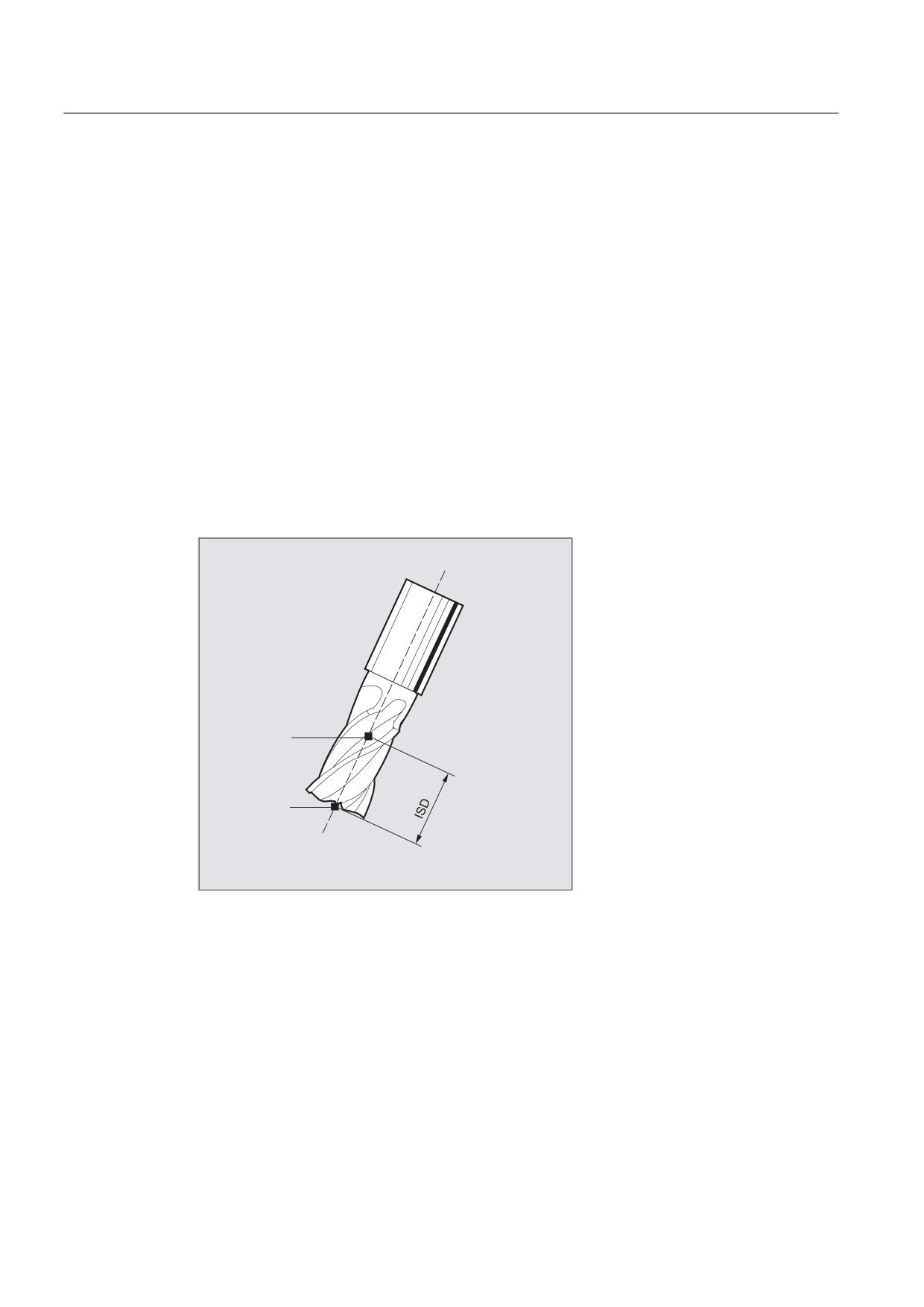
ISD
The clearance (<value>) between the milling tool tip (FS) and the milling tool
construction point (FH) are specified using the command ISD.
Milling tool reference point
The milling tool reference point (FH) is obtained by projecting the programmed machining
point onto the tool axis.
)+
)6
Job Planning
416
Programming Manual, 03/2010, 6FC5398-2BP20-1BA0
Tool offsets
7.5 Activate 3D tool offsets (CUT3DC..., CUT3DF...)
Further Information
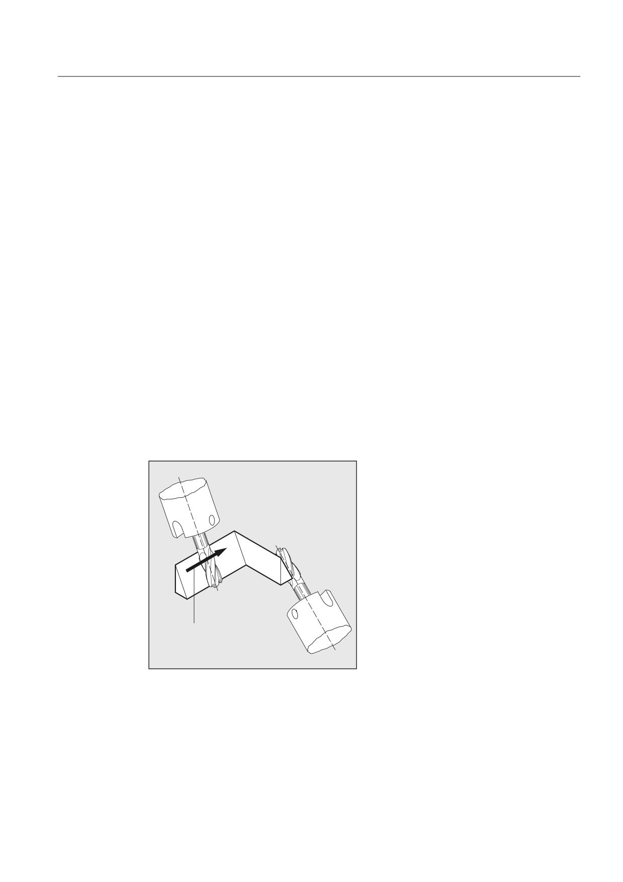
Pocket milling with inclined side walls for circumferential milling with CUT3DC
In this 3D tool radius compensation, a deviation of the mill radius is compensated by infeed
toward the normals of the surface to be machined. The plane, in which the milling tool face is
located, remains unchanged if the insertion depth ISD has remained the same. For example,
a milling tool with a smaller radius than a standard tool would not reach the pocket base,
which is also the limitation surface. For automatic tool infeed, this limitation surface must be
known to the control, see section "3D circumferential milling with limitation surfaces".
For additional information on collision monitoring, refer to:
References:
Programming Manual Basics; Chapter "Tool offsets".
7.5.5
3D tool offset Inside/outside corners and intersection procedure (G450/G451)
Function
Inside corners/outside corners
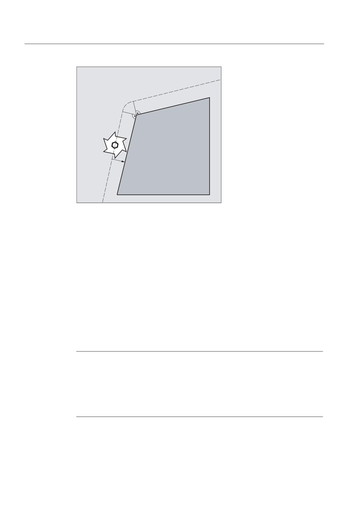
Inside and outside corners are handled separately. The terms inner corner and outer corner
are dependent on the tool orientation.
When the orientation changes at a corner, for example, the corner type may change while
machining is in progress. Whenever this occurs, the machining operation is aborted with an
error message.
0DFKLQLQJ GLUHFWLRQ
Job Planning
Programming Manual, 03/2010, 6FC5398-2BP20-1BA0
417
Tool offsets
7.5 Activate 3D tool offsets (CUT3DC..., CUT3DF...)
Syntax
G450
G451
Significance
G450
Transition circle (tool travels round workpiece corners on a circular path)
G451
Intersection of equidistant paths (tool backs off from the workpiece corner)
Further Information
Intersection procedure for 3D compensation
With 3D circumferential milling, G code G450/G451 is now evaluated i.e. the point of
intersection of the offset curves can be approached. Up to SW 4 a circle was always inserted
at the outside corners. The intersection procedure is especially advantageous for 3D
programs typically generated by CAD. These often consist of short straight blocks (to
approximate smooth curves), where the transitions between adjacent blocks are almost
tangential.
Up to now, with tool radius compensation on the outside of the contour, circles were
generally inserted to circumnavigate the outside corners. These blocks can be very short
with almost tangential transitions, resulting in undesired drops in velocity.
In these cases, analog to the 2 ½ D radius compensation, the two curves involved are
extended; the intersection of both extended curves is approached.
The intersection is determined by extending the offset curves of the two participating blocks
and defining the intersection of the two blocks at the corner in the plane perpendicular to the
tool orientation. If there is not such intersection, the corner is handled as before - i.e. a circle
is inserted.
For more information on the intersection procedure, see:
References:
Function Manual, Special Functions; 3D Tool Radius Compensation (W5)
Job Planning
418
Programming Manual, 03/2010, 6FC5398-2BP20-1BA0
Tool offsets
7.5 Activate 3D tool offsets (CUT3DC..., CUT3DF...)
7.5.6
3D tool offset 3D circumferential milling with limitation surfaces
Adaptation of 3D circumferential milling to the conditions for CAD programs
NC programs generated by CAD systems usually approximate the center path of a standard
tool with a large number of short linear blocks. To ensure that the blocks of many part
contours generated in this way map the original contour as precisely as possible, it is
necessary to make certain changes to the part program.
Important information, which would be required to achieve optimum compensation, that is no
longer available in the part program must be replaced using suitable measures. Here are
some typical methods to compensate critical transitions, either directly in the part program or
when determining the real contour (e.g. using tool infeed).
Applications
In addition to the typical applications for which instead of the standard tool, a real tool
describes the center-point path, cylindrical tools with 3D tool compensation are also
described. In this case, the programmed path refers to the contour on the machining surface.
The associated limitation surface is independent of the tool. Just the same as for
conventional tool radius compensation, the entire radius is used to calculate the
perpendicular offset to the limitation surface.
7.5.7
3D tool offset Taking into consideration a limitation surface (CUT3DCC,
CUT3DCCD)
Function
3D circumferential milling with real tools
In 3D circumferential milling with a continuous or constant change in tool orientation, the tool
center point path is frequently programmed for a defined standard tool. Because in practice
suitable standard tools are often not available, a tool that does not deviate too much from a
standard tool can be used.
CUT3DCCD takes account of a limitation surface for a real differential tool that the programmed
standard tool would define. The NC program defines the center-point path of a standard tool.
CUT3DCC with the use of cylindrical tools takes account of a limitation surface that the
programmed standard tool would have reached. The NC program defines the contour on the
machining surface.
Syntax
CUT3DCCD
CUT3DCC
Job Planning
Programming Manual, 03/2010, 6FC5398-2BP20-1BA0
419

Tool offsets
7.5 Activate 3D tool offsets (CUT3DC..., CUT3DF...)
Significance
CUT3DCCD
Activation of the 3D tool offset for the circumferential milling with
limitation surfaces with a differential tool on the tool center point path:
Infeed to the limitation surface.
CUT3DCC
Activation of the 3D tool offset for circumferential milling with limitation
surfaces with 3D radius compensation: Contour on the machining
surface
Note
Tool radius compensation with G41, G42
If tool radius compensation with G41, G42 is programmed when CUT3DCCD or CUT3DCC is active,
the option "orientation transformation" must also be active.
Standard tools with corner rounding
Corner rounding with a standard tool is defined by the tool parameter $TC_DP7. Tool
parameter $TC_DP16 describes the deviation of the corner rounding of the real tool compared
with the standard tool.
Example
Tool dimensions of a toroidal miller with reduced radius as compared with the standard tool.
Tool type
R = shank radius
r = corner radius
Standard tool with corner rounding
R = $TC_DP6
r = $TC_DP7
Real tool with corner rounding:
R' = $TC_DP6 + $TC_DP15 + OFFN
r' = $TC_DP7 + $TC_DP16
Tool types 121 and 131 torus milling tool
(shaft milling tool)
In this example, both $TC_DP15 + OFFN and $TC_DP16 are negative.
The tool type ($TC_DP1) is evaluated.
Only cutter types with cylindrical shank
For these approved cutter types, the corner radius r is identical to the shank
(cylinder or end mill), toroidal millers (types
radius R. All other permitted tool types are interpreted as cylindrical cutters
121 and 131) and, in the limit case,
and the dimensions specified for the corner rounding are not evaluated.
cylindrical die mills (type 110) are permitted.
All tool types of the numbers 1 - 399, with the
exception of the numbers 111 and 155 to
157, are permitted.
Job Planning
420
Programming Manual, 03/2010, 6FC5398-2BP20-1BA0
Tool offsets
7.5 Activate 3D tool offsets (CUT3DC..., CUT3DF...)
Further Information
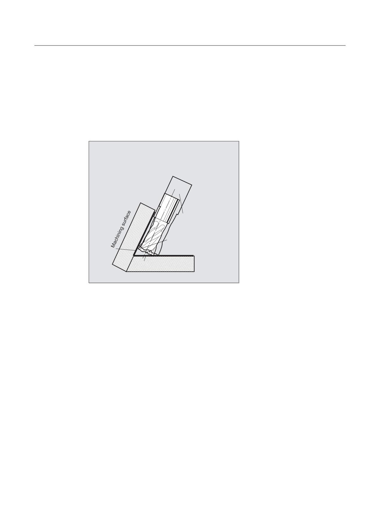
Tool center point path with infeed up to the limitation surface CUT3DCCD
If a tool with a smaller radius than the appropriate standard tool is used, machining is
continued using a milling tool, which is infed in the longitudinal direction until it reaches the
bottom (base) of the pocket. The tool removes as much material from the corner formed by
the machining surface and limitation surface. This involves a machining type combining
circumferential and face milling. Analog to a tool with lower radius, for a tool with increased
radius, the infeed is in the opposite direction.
6WDQGDUG WRRO
7RRO ZLWK VPDOOHU UDGLXV
IHHG WR WKH OLPLWLQJ VXUIDFH
/LPLWLQJ VXUIDFH
Contrary to all other tool offsets of G code group 22, tool parameter $TC_DP6 specified for
CUT3DCCD does not influence the tool radius and the resulting compensation.
The compensation offset is the sum of:
● The wear value of the tool radius (tool parameter $TC_DP15)
● and a tool offset OFFN programmed to calculate the perpendicular offset to the limitation
surface.
The generated part program does not specify whether the surface to be machined is to the
right or left of the path. It is therefore assumed that the radius is a positive value and the
wear value of the original tool is a negative value. A negative wear value always describes a
tool with a lower diameter.
Using cylindrical tools
When cylindrical tools are used, infeed is only necessary if the machining surface and the
surface of limitation form an acute angle (less than 90 degrees). If a torus milling tool
(cylinder with rounded corners) is used, tool infeed in the longitudinal direction is required for
both acute and obtuse angles.
Job Planning
Programming Manual, 03/2010, 6FC5398-2BP20-1BA0
421
Tool offsets
7.5 Activate 3D tool offsets (CUT3DC..., CUT3DF...)
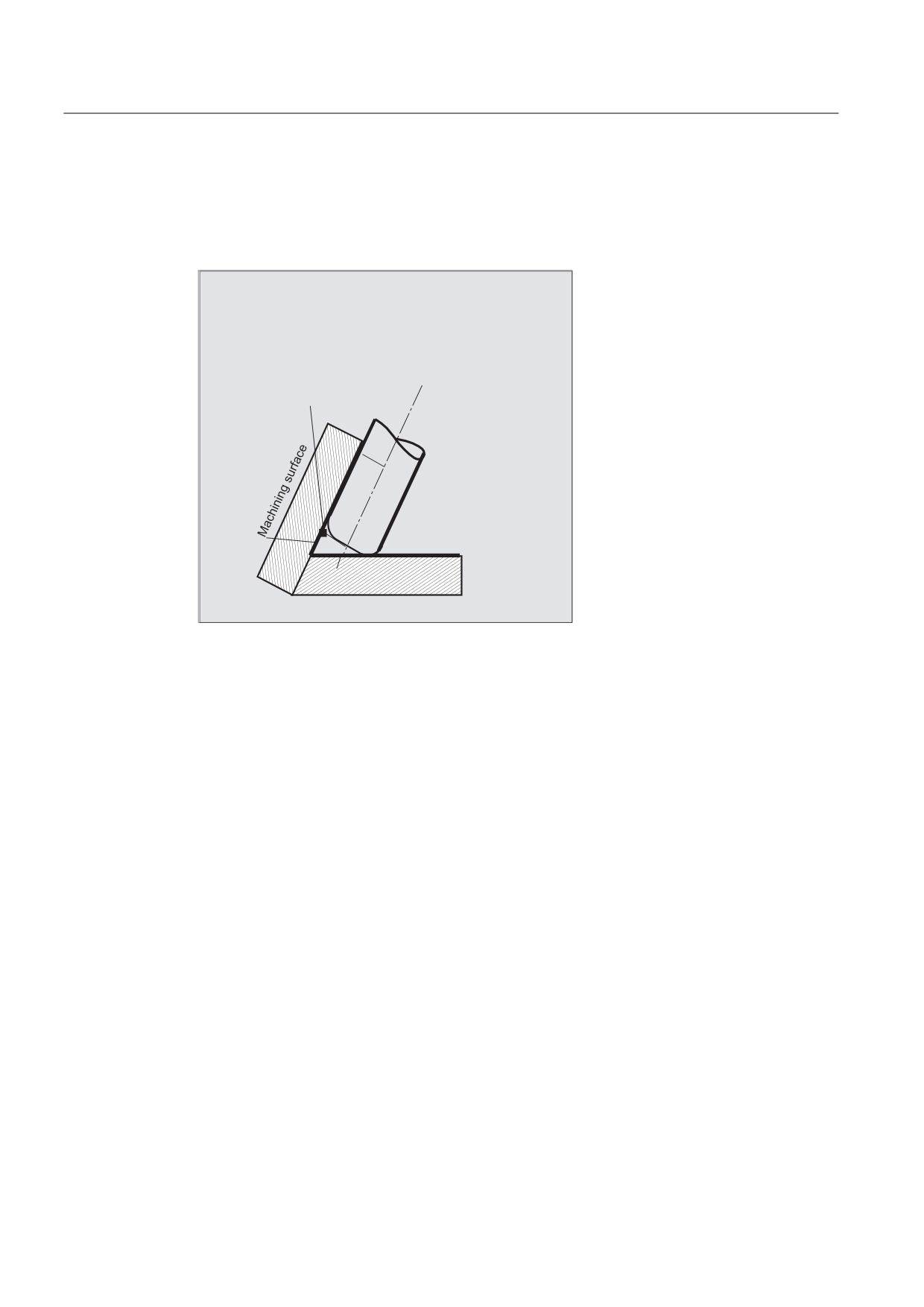
3D radius compensation with CUT3DCC, contour on the machining surface
If CUT3DCC is active with a torus milling tool, the programmed path refers to a fictitious
cylindrical milling tool having the same diameter. The resulting path reference point is shown
in the following diagram for a torus milling tool.
3DWK UHIHUHQFH SRLQW
5
/LPLWLQJ VXUIDFH
The angle between the machining and limitation surfaces may change from an acute to an
obtuse angle and vice versa even within the same block.
The tool actually being used may either be larger or smaller than the standard tool. However,
the resulting corner radius must not be negative and the sign of the resulting tool radius must
be kept.
For CUT3DCC, the NC part program refers to contour on the machining surface. As for
conventional tool radius compensation, the total tool radius is used that comprises the sum
of:
● Tool radius (tool parameter $TC_DP6)
● Wear value (tool parameter $TC_DP15)
● and a tool offset OFFN programmed to calculate the perpendicular offset to the limitation
surface.
The position of the limitation surface is determined from the difference between these two
values:
● Dimensions of the standard tool
● Tool radius (tool parameter $TC_DP6)
Job Planning
422
Programming Manual, 03/2010, 6FC5398-2BP20-1BA0
Tool offsets
7.6 Tool orientation (ORIC, ORID, OSOF, OSC, OSS, OSSE, ORIS, OSD, OST)
7.6
Tool orientation (ORIC, ORID, OSOF, OSC, OSS, OSSE, ORIS,
OSD, OST)
Function
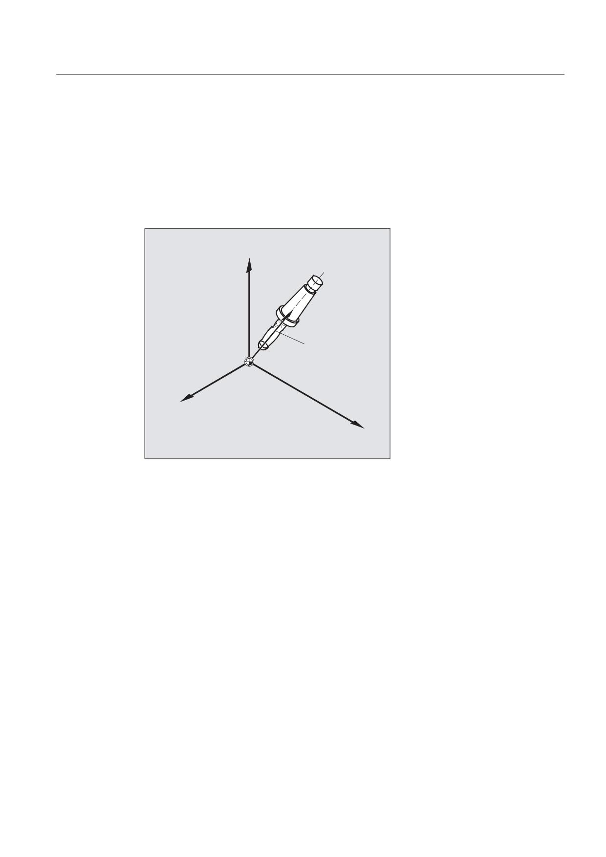
The term tool orientation describes the geometric alignment of the tool in space. The tool
orientation on a 5-axis machine tool can be set by means of program commands.
=
'LUHFWLRQ YHFWRU
;
<
Orientation rounding movements activated with OSD and OST are formed differently depending
on the type of interpolation for tool orientation.
If vector interpolation is active, the smoothed orientation characteristic is also interpolated
using vector interpolation. On the other hand, if rotary axis interpolation is active, the
orientation is smoothed directly using rotary axis movements.
Programming
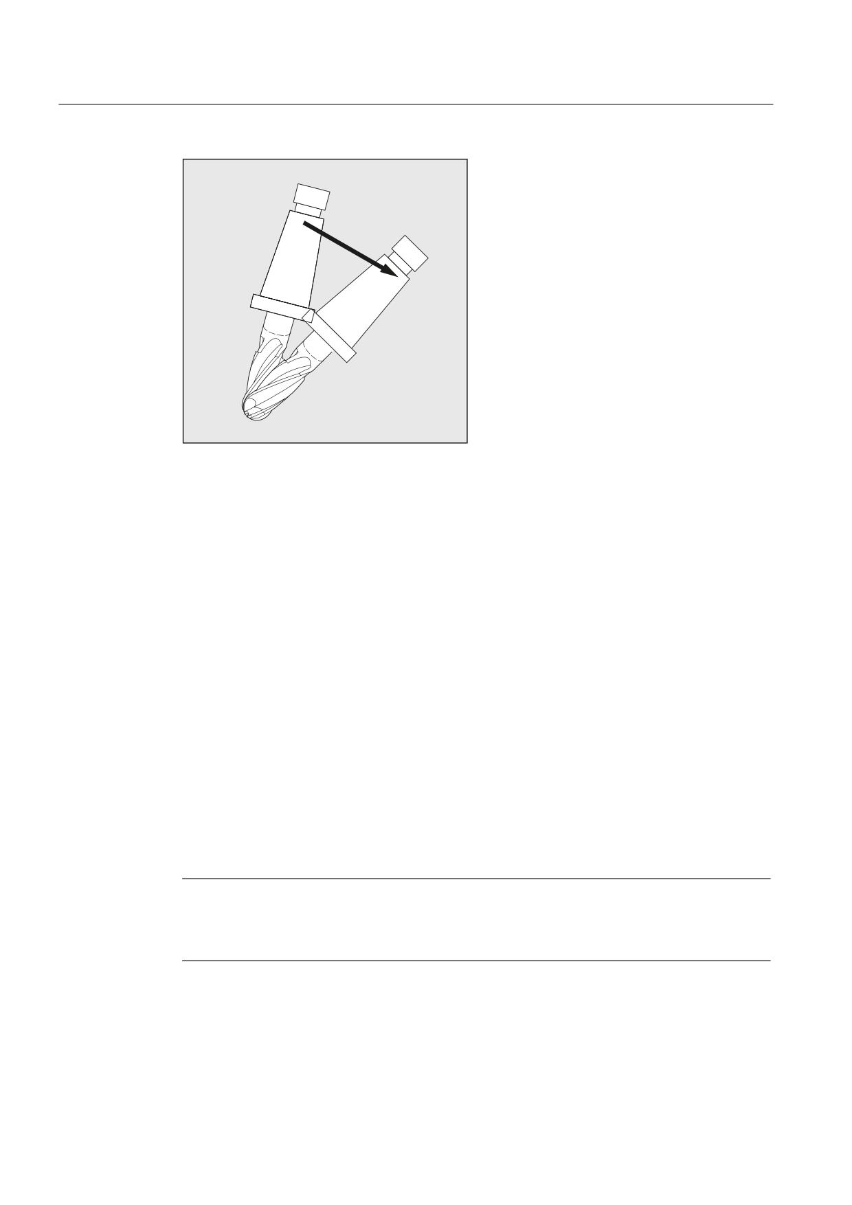
Programming a orientation change:
A change in tool orientation can be programmed by:
● Direct programming of rotary axes A, B, C (rotary axis interpolation)
● Euler or RPY angle
● Direction vector (vector interpolation by specifying A3 or B3 or C3)
● LEAD/TILT (face milling)
The reference coordinate system is either the machine coordinate system (ORIMKS) or the
current workpiece coordinate system (ORIWKS).
Job Planning
Programming Manual, 03/2010, 6FC5398-2BP20-1BA0
423
Tool offsets
7.6 Tool orientation (ORIC, ORID, OSOF, OSC, OSS, OSSE, ORIS, OSD, OST)
2ULHQWDWLRQ
FKDQJH
Programming tool orientation:
Command Significance
ORIC:
Orientation and path movement in parallel
ORID:
Orientation and path movement consecutively
OSOF:
No orientation smoothing
OSC:
Orientation constantly
OSS:
Orientation smoothing only at beginning of block
OSSE:
Orientation smoothing at beginning and end of block
ORIS:
Velocity of the orientation change with orientation smoothing activated in
degrees per mm (valid for OSS and OSSE)
OSD:
Smoothing of orientation by specifying smoothing distance with setting data:
SD42674 $SC_ORI_SMOOTH_DIST
OST:
Smoothing of orientation by specifying angular tolerance in degrees for
vector interpolation with setting data:
SD42676 $SC_ORI_SMOOTH_TOL
With rotary axis interpolation, the specified tolerance is assumed to be the
maximum variance of the orientation axes.
Note
All commands for smoothing the tool orientation (OSOF, OSC, OSS, OSSE, OSD, and OST) are
summarized in G function group 34. They are modal; in other words, only one of these
commands can ever be effective at the same time.
Job Planning
424
Programming Manual, 03/2010, 6FC5398-2BP20-1BA0
Tool offsets
7.6 Tool orientation (ORIC, ORID, OSOF, OSC, OSS, OSSE, ORIS, OSD, OST)
Examples
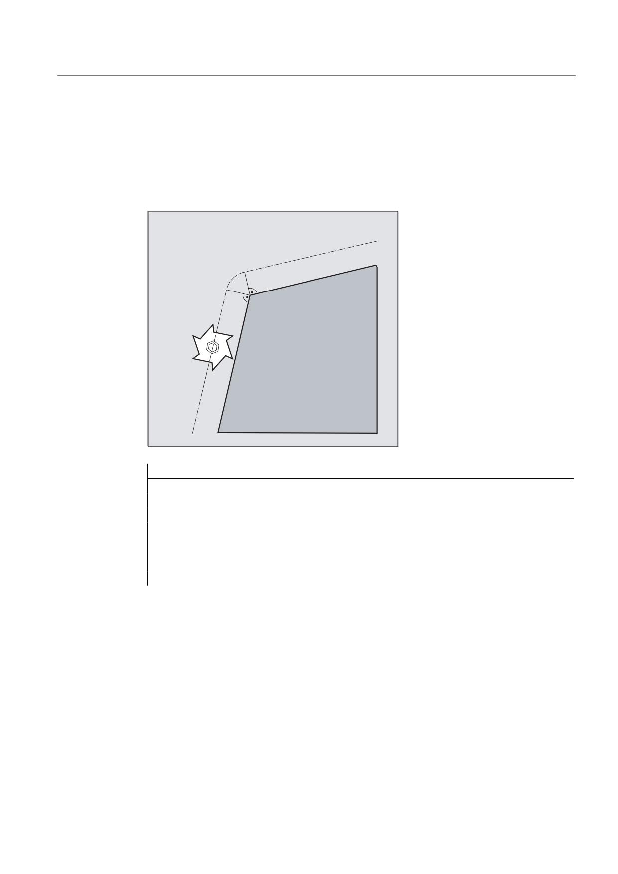
Example 1: ORIC
If ORIC is active and there are two or more blocks with changes in orientation (e.g.A2=...
B2=... C2=...) programmed between traversing blocks N10 andN20, then the inserted circle
block is distributed among these intermediate blocks according to the absolute changes in
angle.
1
1
1
1
Program code
Comments
ORIC
N8 A2=… B2=… C2=…
N10 X… Y… Z…
N12 C2=… B2=…
; The circle block inserted at the external corner is
distributed between N12 and N14, corresponding to
N14 C2=… B2=…
the change in orientation. The circular motion and
the orientation change are executed in parallel.
N20 X =…Y=… Z=… G1 F200
Job Planning
Programming Manual, 03/2010, 6FC5398-2BP20-1BA0
425
Tool offsets
7.6 Tool orientation (ORIC, ORID, OSOF, OSC, OSS, OSSE, ORIS, OSD, OST)
Example 2: ORID
If ORID is active, then all blocks between the two traversing blocks are executed at the end of
the first traversing block. The circle block with constant orientation is executed immediately
before the second traversing block.
3HUIRUP 1
DQG 1
1
1
Program code
Comments
ORID
N8 A2=… B2=… C2=…
N10 X… Y… Z…
N12 A2=… B2=… C2=…
; The N12 and N14 blocks are executed at the end of N10.
The circle block is then executed with the actual
orientation.
N14 M20
; Help functions, etc.
N20 X… Y… Z…
Note
The method which is used to change orientation at an outer contour is determined using the
program command that is active in the first traversing block of an outer corner.
Without change in orientation:If the orientation is not changed at the block boundary, the
cross-section of the tool is a circle, which touches both of the contours.
Job Planning
426
Programming Manual, 03/2010, 6FC5398-2BP20-1BA0
Tool offsets
7.6 Tool orientation (ORIC, ORID, OSOF, OSC, OSS, OSSE, ORIS, OSD, OST)
Example 3: Changing the orientation at an inner corner
1
1
1
:5.
Program code
ORIC
N10 X …Y… Z… G1 F500
N12 X …Y… Z… A2=… B2=… C2=…
N15 X …Y… Z… A2=… B2=… C2=…
Further Information
Behavior at outer corners
A circle block with the radius of the cutter is always inserted at an outside corner.
The ORIC and ORID program commands are used to determine whether changes in
orientation programmed between block N1 and N2 are executed before the inserted circle
block is processed or at the same time.
Job Planning
Programming Manual, 03/2010, 6FC5398-2BP20-1BA0
427
Tool offsets
7.6 Tool orientation (ORIC, ORID, OSOF, OSC, OSS, OSSE, ORIS, OSD, OST)
$ FLUFXODU EORFN ZLOO EH DGGHG
EHWZHHQ EORFN 1 DQG 1
1
1
5
If an orientation change is required at outside corners, this can be performed either at the
same time as interpolation or separately together with the path movement.
When ORID is programmed, the inserted blocks are executed first without path motion. The
circle block generating the corner is inserted immediately before the second of the two
traversing blocks.
If several orientation blocks are inserted at an external corner and ORIC is selected, the
circular motion is distributed among the individual inserted blocks according to the absolute
values of the orientation changes.
Smoothing orientation with OSD or OST
When blending with G642, the maximum variance for the contour axes and orientation axes
cannot vary greatly. The smaller tolerance of the two determines the type of smoothing
motion and/or angular tolerance to smooth the orientation characteristic relatively strongly
without having to accept higher contour deviations.
OSD and OST can be activated to "generously" smooth very slight deviations from the
orientation characteristics with a specified smoothing distance and angular tolerance without
serious contour deviations.
Note
Unlike the process of rounding the contour (and orientation characteristics) with G642, when
rounding the orientation with OSD and/or OST, a separate block is not formed, instead the
rounding movement is added directly to the programmed original blocks.
With OSD and/or OST, block transitions cannot be rounded if there is a change in the type of
interpolation for tool orientation (vector → rotary axis, rotary axis → vector). These block
transitions can if necessary be rounded with the standard rounding functions G641, G642 and
G643.
Job Planning
428
Programming Manual, 03/2010, 6FC5398-2BP20-1BA0
Tool offsets
7.7 Free assignment of D numbers, cutting edge numbers
7.7
Free assignment of D numbers, cutting edge numbers
7.7.1
Free assignment of D numbers, cutting edge numbers (CE address)
D number
The D numbers can be used as contour numbers. You can also address the number of the
cutting edge via the address CE. You can use the system variable $TC_DPCE to describe
the cutting edge number.
Default: compensation no. == tool edge no.
Machine data are used to define the maximum number of D numbers (cutting edge numbers)
and the maximum number of cutting edges per tool (→ machinery construction OEM). The
following commands are only practical if the maximum cutting edge number (MD18105) was
specified to be greater than the number of cutting edges per tool (MD18106). See machine
manufacturer's specifications.
Note
In addition to relative D number allocation, the D numbers can also be assigned as "flat" or
"absolute" D numbers (1-32000) without a reference to a T number (within the "Flat D
number structure" function).
References
Function Manual Basic Functions; Tool Offset (W1)
Job Planning
Programming Manual, 03/2010, 6FC5398-2BP20-1BA0
429
Tool offsets
7.7 Free assignment of D numbers, cutting edge numbers
7.7.2
Free assignment of D numbers: Checking D numbers (CHKDNO)
Function
Using the CKKDNO command, you can check whether the existing D numbers were uniquely
assigned. The D numbers of all tools defined within a TO unit may not occur more than once.
No allowance is made for replacement tools.
Syntax
state=CHKDNO(Tno1,Tno2,Dno)
Significance
state
= TRUE:
The D numbers are assigned uniquely to the
checked areas.
= FALSE:
There was a D number collision or the
parameters are invalid. Tno1, Tno2 and Dno
return the parameters that caused the collision.
These data can now be evaluated in the part
program.
CHKDNO(Tno1,Tno2)
All D numbers of the part specified are checked.
CHKDNO(Tno1)
All D numbers of Tno1 are checked against all other tools.
CHKDNO
All D numbers of all tools are checked against all other tools.
Job Planning
430
Programming Manual, 03/2010, 6FC5398-2BP20-1BA0
Tool offsets
7.7 Free assignment of D numbers, cutting edge numbers
7.7.3
Free assignment of D numbers: Rename D numbers (GETDNO, SETDNO)
Function
You must assign unique D numbers. Two different cutting edges of a tool must not have the
same D number.
GETDNO
This command returns the D number of a particular cutting edge (ce) of a tool with tool
number t. If no D number exists for the entered parameters, d=0 will be set. If the D number
is invalid, a value greater than 32000 is returned.
SETDNO
This command assigns the value d of the D number to a cutting edge ce of tool t. The result
of this statement is returned via state (TRUE or FALSE). If there is no data block for the
specified parameter, the value FALSE is returned. Syntax errors generate an alarm. The D
number cannot be set explicitly to 0.
Syntax
d = GETDNO (t,ce)
state = SETDNO (t,ce,d)
Significance
d
D number of the tool edge
t
T number of the tool
ce
Cutting edge number (CE number) of the tool
state Indicates whether the command could be executed (TRUE or FALSE).
Example for renaming a D number
Programming
Comments
$TC_DP2[1.2]=120
;
$TC_DP3[1,2] = 5.5
;
$TC_DPCE[1,2] = 3
; Cutting edge number CE
;
N10 def int DNoOld, DNoNew = 17
;
N20 DNoOld = GETDNO(1,3)
;
N30 SETDNO(1,3,DNoNew)
;
The new D value 17 is then assigned to cutting edge CE=3. Now the data for the cutting
edge are addressed via D number 17; both via the system variables and in the programming
with the NC address.
Job Planning
Programming Manual, 03/2010, 6FC5398-2BP20-1BA0
431
Tool offsets
7.7 Free assignment of D numbers, cutting edge numbers
7.7.4
Free assignment of D numbers: Determine T number to the specified D number
(GETACTTD)
Function
You determine the T number associated with an absolute D number using the GETACTTD
command. There is not check for uniqueness. If several D numbers within a TO unit are the
same, the T number of the first tool found in the search is returned. This command is not
suitable for use with "flat" D numbers, because the value "1" is always returned in this case
(no T numbers in database).
Syntax
status=GETACTTD(Tnr,Dnr)
Significance
Dno
D number for which the T number shall be searched.
Tno
T number found
status
Value:
Significance:
0
The T number has been found. Tno contains the value of the T
number.
-1
No T number exists for the specified D number; Tno=0.
-2
The D number is not absolute. Tno receives the value of the first
found tool, that contains the D number with the value Dno.
-5
The function was not able to be executed for another reason.
Job Planning
432
Programming Manual, 03/2010, 6FC5398-2BP20-1BA0
Tool offsets
7.7 Free assignment of D numbers, cutting edge numbers
7.7.5
Free assignment of D numbers: Invalidate D numbers (DZERO)
Function
The DZERO command is used for support during retooling. Compensation data sets tagged
with this command are no longer verified by the CHKDNO command. These data sets can be
accessed again by setting the D number once more with SETDNO.
Syntax
DZERO
Significance
DZERO
Marks all D numbers of the TO unit as invalid.
Job Planning
Programming Manual, 03/2010, 6FC5398-2BP20-1BA0
433
Tool offsets
7.8 Tool holder kinematics
7.8
Tool holder kinematics
Prerequisites
A toolholder can only orientate a tool in all possible directions in space if
● two rotary axes V1 and V2 are present.
● the rotary axes are mutually orthogonal.
● the tool longitudinal axis is perpendicular to the second rotary axis V2.
In addition, the following requirement is applicable to machines for which all possible
orientations have to be settable:
● the tool longitudinal axis must be perpendicular to the first rotary axis V1.
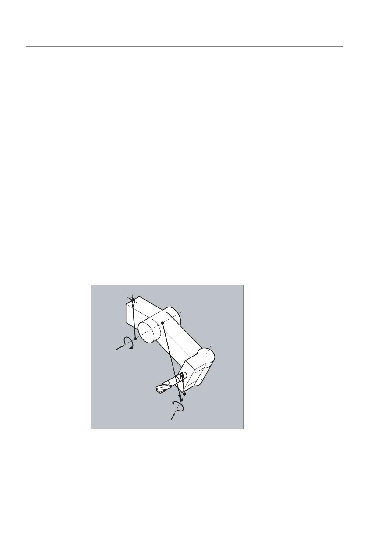
Function
The toolholder kinematics with a maximum of two rotary axes v1 or v2 are defined using the
17 system variables $TC_CARR1[m] to $TC_CARR17[m]. The description of the toolholder
consists of:
● the vectoral distance from the first rotary axis of the toolholder I1, the vectoral distance
from the first rotary axis to the second rotary axis I2, the vectoral distance from the
second rotary axis to the reference point of the tool I3.
● the direction vectors of both rotary axes V1, V2.
● the rotational angles α1, α2 at the two axes. The rotation angles are counted in viewing
direction of the rotary axis vectors, positive, in clockwise direction of rotation.
O
9
˞
O
O
˞
9
For machines with resolved kinematics (both the tool and the part can rotate), the system
variables have been extended with the entries
● $TC_CARR18[m] to $TC_CARR23[m].
Job Planning
434
Programming Manual, 03/2010, 6FC5398-2BP20-1BA0

Tool offsets
7.8 Tool holder kinematics
Parameters
Function of the system variables for orientable toolholders
Designation
x component
y component
y component
l1 offset vector
$TC_CARR1[m]
$TC_CARR2[m]
$TC_CARR3[m]
l2 offset vector
$TC_CARR4[m]
$TC_CARR5[m]
$TC_CARR6[m]
v1 rotary axis
$TC_CARR7[m]
$TC_CARR8[m]
$TC_CARR9[m]
v2 rotary axis
$TC_CARR10[m]
$TC_CARR11[m]
$TC_CARR12[m]
α1 angle of
$TC_CARR13[m]
rotation
$TC_CARR14[m]
α2 angle of
rotation
l3 offset vector
$TC_CARR15[m]
$TC_CARR16[m]
$TC_CARR17[m]
Extensions of the system variables for orientable toolholders
Name
x component
y component
z component
l4 offset vector
$TC_CARR18[m]
$TC_CARR19[m]
$TC_CARR20[m]
Axis identifier
Axis identifier of the rotary axes v1 and v2 (initialized with zero)
rotary axis v1
$TC_CARR21[m]
rotary axis v2
$TC_CARR22[m]
Kinematic type
$TC_CARR23[m]
Tool
Kinematics type T ->
Kinematics type P ->
Kinematics type M
Part
Only the tool can rotate
Only the part can rotate
Part and tool can rotate
Mixed mode
(default).
Offset of the
Angle in degrees of the rotary axes v1 and v2 on assuming the initial setting
rotary axis v1
$TC_CARR24[m]
rotary axis v2
$TC_CARR25[m]
Angle offset of
Offset of the Hirth tooth system in degrees for rotary axes v1 and v2
the rotary axis v1
$TC_CARR26[m]
rotary axis v2
$TC_CARR27[m]
Angle increment
Offset of the Hirth tooth system in degrees for rotary axes v1 and v2
v1 rotary axis
$TC_CARR28[m]
v2 rotary axis
$TC_CARR29[m]
Min. position
Software limit for the minimum position of the rotary axes v1 and v2
rotary axis v1
$TC_CARR30[m]
rotary axis v2
$TC_CARR31[m]
Max. position
Software limits for the maximum position of the rotary axes v1 and v2
rotary axis v1
$TC_CARR32[m]
rotary axis v2
$TC_CARR33[m]
Toolholder name
A toolholder can be given a name instead of a number. $TC_CARR34[m]
User:
Intended use in user measuring cycles $TC_CARR35[m]
Axis name 1
$TC_CARR36[m]
Axis name 2
$TC_CARR37[m]
Identifier
$TC_CARR38[m]
$TC_CARR39[m]
$TC_CARR40[m]
Position
Job Planning
Programming Manual, 03/2010, 6FC5398-2BP20-1BA0
435

Tool offsets
7.8 Tool holder kinematics
Extensions of the system variables for orientable toolholders
Fine
Parameters that can be added to the values
offset
in the basic parameters.
l1 Offset vector
$TC_CARR41[m]
$TC_CARR42[m]
$TC_CARR43[m]
l2 Offset vector
$TC_CARR44[m]
$TC_CARR45[m]
$TC_CARR46[m]
l3 Offset vector
$TC_CARR55[m]
$TC_CARR56[m]
$TC_CARR57[m]
l4 Offset vector
$TC_CARR58[m]
$TC_CARR59[m]
$TC_CARR60[m]
v1 rotary axis
$TC_CARR64[m]
v2 rotary axis
$TC_CARR65[m]
Note
Explanations of parameters
"m" specifies the number of the toolholder to be programmed.
$TC_CARR47 to $TC_CARR54 and $TC_CARR61 to $TC_CARR63 are not defined and produce an
alarm if read or write access is attempted.
The start/endpoints of the distance vectors on the axes can be freely selected. The rotation
angles α1, α2 about the two axes are defined in the initial state of the toolholder by 0°. In this
way, the kinematics of a toolholder can be programmed for any number of possibilities.
Toolholders with only one or no rotary axis at all can be described by setting the direction
vectors of one or both rotary axes to zero.
With a toolholder without rotary axis the distance vectors act as additional tool
compensations whose components cannot be affected by a change of machining plane (G17
to G19).
Parameter extensions
Parameters of the rotary axes
The system variables have been extended by the entries $TC_CARR24[m] to
$TC_CARR33[m] and described as follows:
Offset of rotary axes
Changing the position of the rotary axis v1 or v2 for the initial setting of the
v1, v2
oriented toolholder.
The angle
The offset or the angle increment of the Hirth tooth system of the rotary axes
offset/angle
v1 and v2. Programmed or calculated angle is rounded up to the next value
increment of the
that results from phi = s + n * d when n is an integer.
rotary axes v1, v2
The minimum and
The minimum and maximum position of the rotary axis limit angle (software
maximum position of
limit) of the rotary axes v1 and v2.
the rotary axes v1, v2
Parameters for the user
$TC_CARR34 to $TC_CARR40 contain parameters that are freely available to users and up
to SW 6.4 were as standard, not further evaluated within the NCK or had no significance.
Job Planning
436
Programming Manual, 03/2010, 6FC5398-2BP20-1BA0
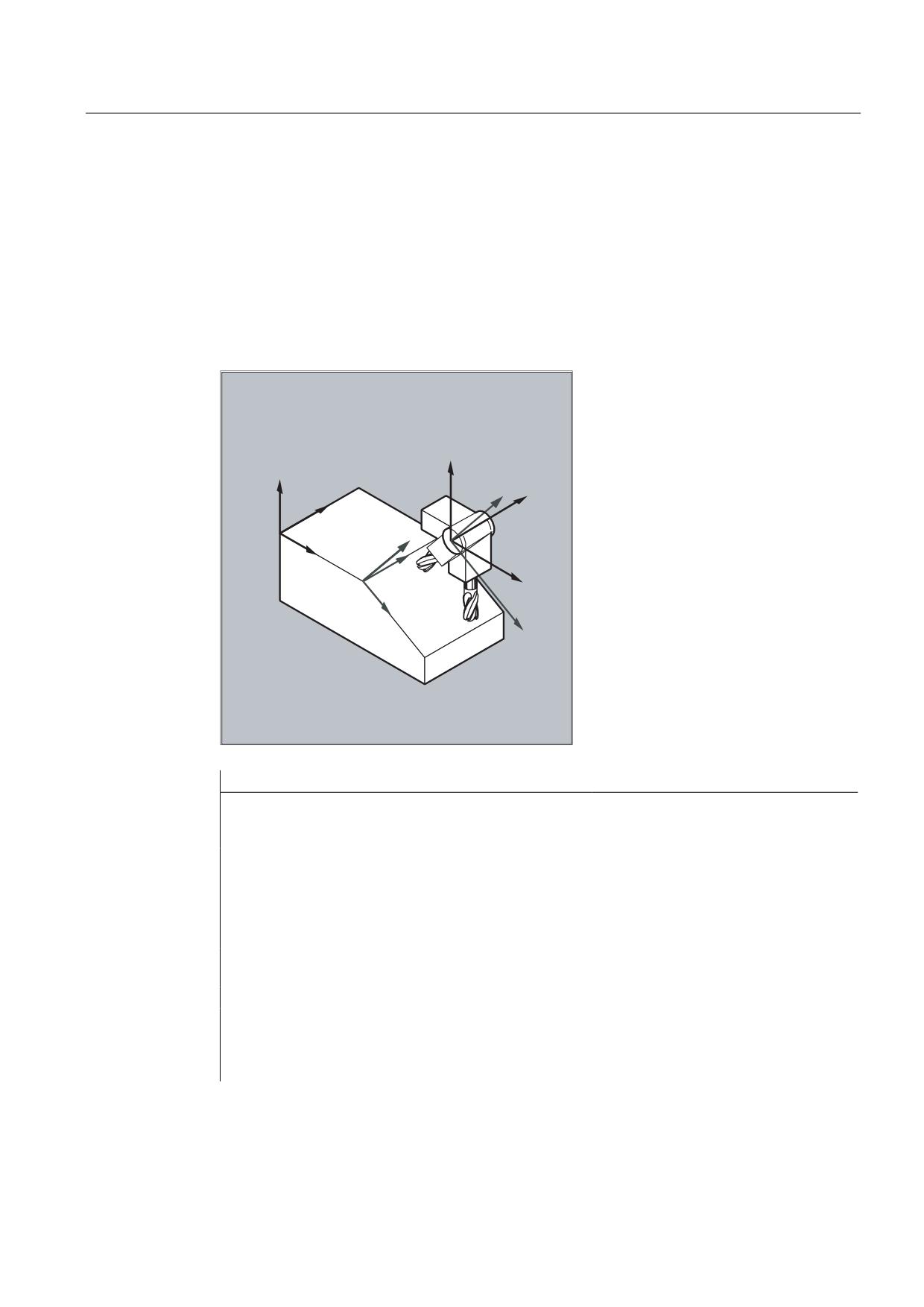
Tool offsets
7.8 Tool holder kinematics
Fine offset parameters
$TC_CARR41 to $TC_CARR65 include fine offset parameters that can be added to the
values in the basis parameters. The fine offset value assigned to a basic parameter is
obtained when the value 40 is added to the parameter number.
Example
The toolholder used in the following example can be fully described by a rotation around the
Y axis.
]
]
=
<
<
=
;
<
;
;
;
Program code
Comments
N10 $TC_CARR8[1]=1
; Definition of the Y component of
the first rotary axis of
toolholder 1.
N20 $TC_DP1[1,1] = 120
; Definition of a shaft miller.
N30 $TC_DP3[1,1]=20
; Definition of a shaft miller, 20
mm long.
N40 $TC_DP6[1,1]=5
; Definition of a shaft miller with
5 mm radius.
N50 ROT Y37
; Frame definition with 37° rotation
around the Y axis.
N60 X0 Y0 Z0 F10000
; Approach starting position.
N70 G42 CUT2DF TCOFR TCARR=1 T1 D1 X10
; Set radius compensation, tool
length compensation in rotated
frame, select toolholder 1, tool
1.
Job Planning
Programming Manual, 03/2010, 6FC5398-2BP20-1BA0
437
Tool offsets
7.8 Tool holder kinematics
Program code
Comments
N80 X40
; Perform machining under a rotation
of 37°.
N90 Y40
N100 X0
N110 Y0
N120 M30
Further Information
Resolved kinematics
For machines with resolved kinematics (both the tool as well as the workpiece can be
rotated), the system variables have been expanded by the entries $TC_CARR18[m] up to
$TC_CARR23[m] and are described as follows:
The rotatable tool table consisting of:
● The vectorial clearance of the second rotary axis V2 to the reference point of a tool table
that can be rotated I4 of the third rotary axis.
The rotary axes consisting of:
● The two channel identifiers for the reference of the rotary axes V1and V2, whose position
is, when required, accessed to determine the orientation of the toolholder that can be
orientated.
The type of kinematics with one of the values T, P or M:
● Kinematics type T: Only tool can rotate.
● Kinematics type P: Only part can rotate.
● Kinematics type M: Tool and part can rotate.
Clearing the toolholder data
Data of all toolholder data sets can be deleted using $TC_CARR1[0]=0.
The kinematic type $TC_CARR23[T]=T must be assigned with one of the three permissible
upper or lower case letters (T,P,M) and for this reason, should not be deleted.
Changing the toolholder data
Each of the described values can be modified by assigning a new value in the part program.
Any character other than T, P or M results in an alarm when an attempt is made to activate
the toolholder that can be orientated.
Reading the toolholder data
Each of the described values can be read by assigning it to a variable in the part program.
Fine offsets
An illegal fine offset value is only detected if a toolholder that can be orientated is activated,
which contains such a value and at the same time setting data
SD42974 $SC_TOCARR_FINE_CORRECTION = TRUE.
The maximum permissible fine offset is limited to a permissible value in the machine data.
Job Planning
438
Programming Manual, 03/2010, 6FC5398-2BP20-1BA0
Tool offsets
7.9 Tool length compensation for orientable toolholders (TCARR, TCOABS, TCOFR, TCOFRX, TCOFRY, TCOFRZ)
7.9
Tool length compensation for orientable toolholders (TCARR,
TCOABS, TCOFR, TCOFRX, TCOFRY, TCOFRZ)
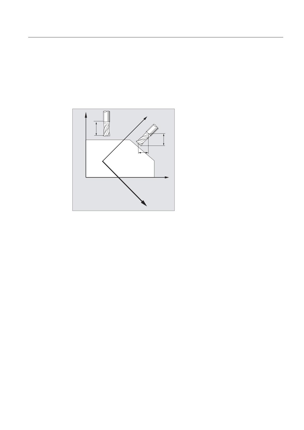
Function
When the spatial orientation of the tool changes, its tool length components also change.
=
=
,
,
,
;
;
After a reset, e.g., through manual setting or change of the toolholder with a fixed spatial
orientation, the tool length components also have to be determined again. This is performed
using the TCOABS and TCOFR path commands.
For a toolholder of an active frame that can be orientated, when selecting the tool with
TCOFRZ, TCOFRY and TCOFRX, it is possible to define the direction in which the tool should point.
Syntax
TCARR=[<m>]
TCOABS
TCOFR
TCOFRZ
TCOFRY
TCOFRX
Job Planning
Programming Manual, 03/2010, 6FC5398-2BP20-1BA0
439
Tool offsets
7.9 Tool length compensation for orientable toolholders (TCARR, TCOABS, TCOFR, TCOFRX, TCOFRY,
TCOFRZ)
Significance
TCARR=[<m>]:
Request toolholder with the number "m"
TCOABS:
Determine tool length components from the orientation of the current
toolholder
TCOFR:
Determine tool length components from the orientation of the active
frame
TCOFRZ:
Orientable toolholder from active frame with a tool pointing in the Z
direction
TCOFRY:
Orientable toolholder from active frame with a tool pointing in the Y
direction
TCOFRX:
Orientable toolholder from active frame with a tool pointing in the X
direction
Further Information
Determine tool length compensation from the orientation of the toolholder (TCOABS)
TCOABS calculates the tool length compensation from the current orientation angles of the
toolholder; saved in the system variables $TC_CARR13 and $TC_CARR14.
For a definition of toolholder kinematics with system variables, see "Toolholder kinematics
(Page 434)".
In order to make a new calculation of the tool length compensation when frames are
changed, the tool has to be selected again.
Tool direction from active frame
The toolholder with orientation capability is set so that the tool points in the following
directions.
● with TCOFR or TCOFRZ in the Z direction
● with TCOFRY in the Y direction
● with TCOFRX in the X direction
The tool length compensation is re-calculated when changing over between TCOFR and
TCOABS.
Request toolholder (TCARR)
With TCARR, the toolholder number m is requested with its geometry data (compensation
memory).
With m=0, the active toolholder is deselected.
The geometry data of the toolholder only become active after a tool is called. The selected
tool remains active after a toolholder change has taken place.
The current geometry data for the toolholder can also be defined in the part program via the
corresponding system variables.
Job Planning
440
Programming Manual, 03/2010, 6FC5398-2BP20-1BA0
Tool offsets
7.9 Tool length compensation for orientable toolholders (TCARR, TCOABS, TCOFR, TCOFRX, TCOFRY, TCOFRZ)
Recalculation of tool length compensation (TCOABS) for a frame change
In order to make a new calculation of the tool length compensation when frames are
changed, the tool has to be selected again.
Note
The tool orientation must be manually adapted to the active frame.
When the tool length compensation is calculated, the angle of rotation of the toolholder is
calculated in an intermediate step. With toolholders with two rotary axes, there are generally
two sets of rotation angles, which can be used to adapt the tool orientation to the active
frame; therefore, the rotation angle values stored in the system variables must at least
correspond approximately to the mechanically set rotation angles.
Note
Tool orientation
It is not possible for the control to check whether the rotation angles calculated by means of
the frame orientation are settable on the machine.
If the rotary axes of the toolholder are arranged such that the tool orientation calculated by
means of the frame orientation cannot be reached, then an alarm is output.
The combination of tool precision compensation and the functions for tool length
compensation on movable toolholders is not permissible. If both functions are called
simultaneously, an error message is issued.
The TOFRAME function allows a frame to be defined on the basis of the direction of orientation
of the selected toolholder. For more information please refer to chapter "Frames".
When orientation transformation is active (3, 4 or 5-axis transformation), it is possible to
select a toolholder with an orientation deviating from the zero position without causing output
of an alarm.
Job Planning
Programming Manual, 03/2010, 6FC5398-2BP20-1BA0
441
Tool offsets
7.9 Tool length compensation for orientable toolholders (TCARR, TCOABS, TCOFR, TCOFRX, TCOFRY,
TCOFRZ)
Transfer parameter from standard and measuring cycles
For the transfer parameter of standard and measuring cycles, the following defined value
ranges apply.
For angular value, the value range is defined as follows:
● Rotation around 1st geometry axis: -180 degrees to +180 degrees
● Rotation around 2nd geometry axis: -90 degrees to +90 degrees
● Rotation around 3rd geometry axis: -180 degrees to +180 degrees
Refer to Chapter Frames, "Programmable rotation (ROT, AROT, RPL)".
Note
When transferring angular values to a standard or measuring cycle, the following should be
carefully observed:
Values less than the calculation resolution of the NC should be rounded-off to zero!
The calculation resolution of the NC for angular positions is defined in the machine data:
MD10210 $MN_INT_INCR_PER_DEG
Job Planning
442
Programming Manual, 03/2010, 6FC5398-2BP20-1BA0
Tool offsets
7.10 Online tool length compensation (TOFFON, TOFFOF)
7.10
Online tool length compensation (TOFFON, TOFFOF)
Function
Use the system variable $AA_TOFF[<n> ] to overlay the effective tool lengths in accordance
with the three tool directions three-dimensionally in real time.
The three geometry axis identifiers are used as index <n>. This defines the number of active
directions of compensation by the geometry axes active at the same time.
All compensations can be active at the same time.
The online tool length compensation function can be used for:
● orientation transformation TRAORI
● orientable toolholder TCARR
Note
Online tool length compensation is an option, which must be enabled in advance. This
function is only practical in conjunction with an active orientation transformation or an
active orientable toolholder.
Syntax
TRAORI
TOFFON(<compensation direction>[,<offset value>])
WHEN TRUE DO $AA_TOFF[<compensation direction>]
; In synchronized actions.
TOFFOF(<compensation direction>)
For more information about programming online tool length compensation in motion-
synchronous actions, see "Online tool length compensation ($AA_TOFF) (Page 596)".
Meaning
TOFFON
:
Activate online tool length compensation
<compensation direction>: Tool direction (X, Y, Z), in which the online tool
length compensation should be active.
<offset value>:
When activating, an offset value can be
specified for the relevant direction of
compensation and this is immediately
recovered.
TOFFOF:
Reset online tool length compensation
The compensation values in the specified compensation direction are reset
and a pre-processing stop is initiated.
Job Planning
Programming Manual, 03/2010, 6FC5398-2BP20-1BA0
443
Tool offsets
7.10 Online tool length compensation (TOFFON, TOFFOF)
Examples
Example 1: Selecting the tool length compensation
Program code
Comment
MD21190 $MC_TOFF_MODE = 1
; Absolute values are approached.
MD21194 $MC_TOFF_VELO[0] =1000
MD21196 $MC_TOFF_VELO[1] =1000
MD21194 $MC_TOFF_VELO[2] =1000
MD21196 $MC_TOFF_ACCEL[0] =1
MD21196 $MC_TOFF_ACCEL[1] =1
MD21196 $MC_TOFF_ACCEL[2] =1
N5 DEF REAL XOFFSET
N10 TRAORI(1)
; Transformation on.
N20 TOFFON(Z)
; Activation of online tool length
compensation for the Z tool
direction.
N30 WHEN TRUE DO $AA_TOFF[Z]=10 G4 F5
; A TLC of 10 is interpolated for the
Z tool direction.
N100 XOFFSET=$AA_TOFF_VAL[X]
; Assigns actual compensation in the X
direction.
N120 TOFFON(X,-XOFFSET) G4 F5
; For the X tool direction, the TLC is
reduced back to 0.
Example 2: Deselect the tool length compensation
Program code
Comment
N10 TRAORI(1)
; Transformation on.
N20 TOFFON(X)
; Activation of online tool length
compensation for the X tool
direction.
N30 WHEN TRUE DO $AA_TOFF[X]=10 G4 F5
; A TLC of 10 is interpolated for the
X tool direction.
N80 TOFFOF(X)
; Position offset of the X tool
direction is deleted:
...$AA_TOFF[X]=0
No axis is moved.
The position offset is added to the
actual position in the WCS
corresponding to the
actual orientation.
Job Planning
444
Programming Manual, 03/2010, 6FC5398-2BP20-1BA0
Tool offsets
7.10 Online tool length compensation (TOFFON, TOFFOF)
Further information
Block preparation
During block preparation in preprocessing, the current tool length offset active in the main
run is also taken into consideration. To allow extensive use to be made of the maximum
permissible axis velocity, it is necessary to stop block preparation with a STOPRE
preprocessing stop while a tool offset is established.
The tool offset is always known at the time of run-in when the tool length offsets are not
changed after program start or if more blocks have been processed after changing the tool
length offsets than the IPO buffer can accommodate between run-in and main run.
Variable $AA_TOFF_PREP_DIFF
The dimension for the difference between the currently active compensation in the
interpolator and the compensation that was active at the time of block preparation can be
polled in the variable $AA_TOFF_PREP_DIFF[<n>].
Adjusting machine data and setting data
The following system data is available for online tool length offset:
● MD20610 $MC_ADD_MOVE_ACCEL_RESERVE (acceleration margin for overlaid
motion)
● MD21190 $MC_TOFF_MODE
Content of system variable$AA_TOFF[<n>] is moved through as absolute value or is
integrated up.
● MD21194 $MC_TOFF_VELO (velocity of the online tool length compensation)
● MD21196 $MC_TOFF_ACCEL (acceleration of the online tool length compensation)
● Setting data for presetting limit values:
SD42970 $SC_TOFF_LIMIT (upper limit of the tool length compensation value)
Reference:
Function Manual, Special Functions; F2: Multi-axis transformations
Job Planning
Programming Manual, 03/2010, 6FC5398-2BP20-1BA0
445
Tool offsets
7.11 Cutting data modification for tools that can be rotated (CUTMOD)
7.11
Cutting data modification for tools that can be rotated (CUTMOD)
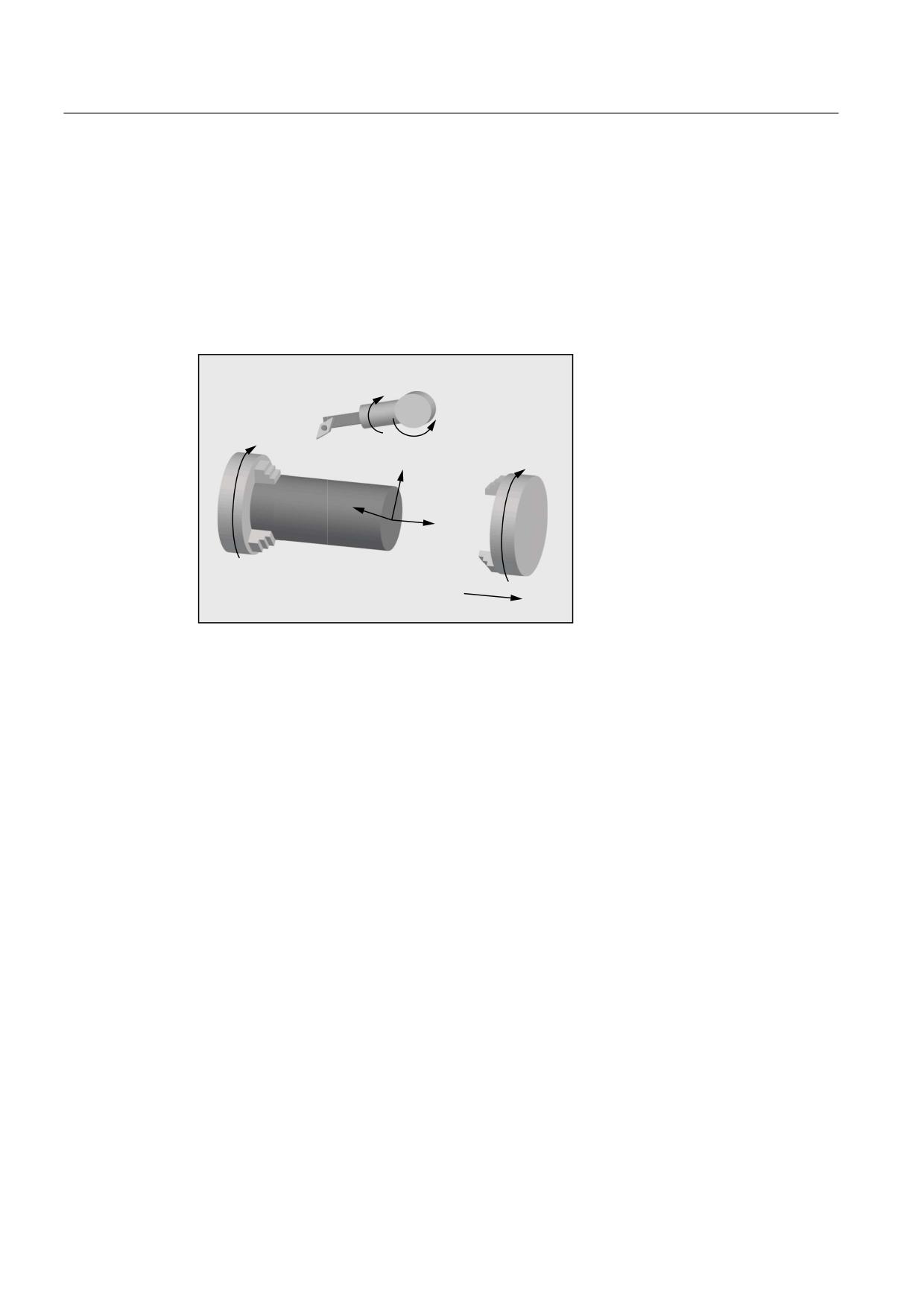
Function
Using the function "cutting data modification for rotatable tools", the changed geometrical
relationships, that are obtained relative to the workpiece being machined when rotating tools
(predominantly turning tools, but also drilling and milling tools) can be taken into account with
the tool compensation.
7RRO VSLQGOH
% D[LV
0DLQ VSLQGOH
&
&
%
&RXQWHUVSLQGOH
&
;
<
=
=
Figure 7-1
Rotatable tool for a lathe
The actual tool rotation is always determined from a currently active toolholder that can be
orientated (refer to " Tool length compensation for toolholders that can be orientated
(Page 439)").
The function is activated using the command CUTMOD.
Syntax
CUTMOD=<value>
Job Planning
446
Programming Manual, 03/2010, 6FC5398-2BP20-1BA0
Tool offsets
7.11 Cutting data modification for tools that can be rotated (CUTMOD)
Meaning
CUTMOD
Command to switch-in the function "cutting data modification for tools that can
be rotated"
<value>
The following values can be assigned to the CUTMOD command:
0
The function is deactivated.
The values supplied from system variables $P_AD... are the same as
the corresponding tool parameters.
> 0
The function is activated if a toolholder that can be orientated with the
specified number is active, i.e. the activation is linked to a specific
toolholder that can be orientated.
The values supplied from system variables $P_AD... may be modified
with respect to the corresponding tool parameters depending on the
active rotation.
The deactivation of the designated toolholder that can be orientated
temporarily deactivates the function; the activation of another
toolholder that can be orientated permanently deactivates it. This is
the reason that in the first case, the function is re-activated when
again selecting the same toolholder that can be orientated; in the
second case, a new selection is required - even if at a subsequent
time, the toolholder that can be orientated is re-activated with the
specified number.
The function is not influenced by a reset.
-1
The function is always activated if a toolholder that can be orientated
is active.
When changing the toolholder or when de-selecting it and a
subsequent new selection, CUTMOD does not have to be set again.
-2
The function is always activated if a toolholder that can be orientated
is active whose number is the same as the currently active toolholder
that can be orientated.
If a toolholder that can be orientated is not active, then this has the
same significance as CUTMOD=0. If a toolholder that can be orientated is
active, then this has the same significance as when directly specifying
the actual toolholder number.
< -2
Values less than -2 are ignored, i.e. this case is treated as if CUTMOD
was not programmed.
Note:
This value range should not be used as it is reserved for possible
subsequent expansions.
Note
SD42984 $SC_CUTDIRMOD
The function can be activated using the CUTMOD command replaces the function that can be
activated using the setting data SD42984 $SC_CUTDIRMOD. However, this function
remains available unchanged. However, as it doesn't make sense to use both functions in
parallel, it can only be activated if CUTMOD is equal to zero.
Job Planning
Programming Manual, 03/2010, 6FC5398-2BP20-1BA0
447
Tool offsets
7.11 Cutting data modification for tools that can be rotated (CUTMOD)
Example
The following example refers to a tool with tool nose position 3 and a toolholder that can be
orientated, which can rotate the tool around the B axis.
The numerical values in the comments specify the end of block positions in the machine
coordinates (MCS) in the sequence X, Y, Z.
Program code
Comment
N10 $TC_DP1[1,1]=500
N20 $TC_DP2[1,1]=3
;
Tool nose position
N30 $TC_DP3[1,1]=12
N40 $TC_DP4[1,1]=1
N50 $TC_DP6[1,1]=6
N60 $TC_DP10[1,1]=110
;
Holder angle
N70 $TC_DP11[1,1]=3
;
Cut direction
N80 $TC_DP24[1,1]=25
;
Clearance angle
N90 $TC_CARR7[2]=0 $TC_CARR8[2]=1 $TC_CARR9[2]=0
;
B axis
N100 $TC_CARR10[2]=0 $TC_CARR11[2]=0 $TC_CARR12[2]=1
;
C axis
N110 $TC_CARR13[2]=0
N120 $TC_CARR14[2]=0
N130 $TC_CARR21[2]=X
N140 $TC_CARR22[2]=X
N150 $TC_CARR23[2]="M"
N160 TCOABS CUTMOD=0
N170 G18 T1 D1 TCARR=2
X
Y
Z
N180 X0 Y0 Z0 F10000
;
12.000
0.000
1.000
N190 $TC_CARR13[2]=30
N200 TCARR=2
N210 X0 Y0 Z0
;
10.892
0.000
-5.134
N220 G42 Z-10
;
8.696
0.000
-17.330
N230 Z-20
;
8.696
0.000
-21.330
N240 X10
;
12.696
0.000
-21.330
N250 G40 X20 Z0
;
30.892
0.000
-5.134
N260 CUTMOD=2 X0 Y0 Z0
;
8.696
0.000
-7.330
N270 G42 Z-10
;
8.696
0.000
-17.330
N280 Z-20
;
8.696
0.000
-21.330
N290 X10
;
12.696
0.000
-21.330
N300 G40 X20 Z0
;
28.696
0.000
-7.330
N310 M30
Job Planning
448
Programming Manual, 03/2010, 6FC5398-2BP20-1BA0
Tool offsets
7.11 Cutting data modification for tools that can be rotated (CUTMOD)
Explanations:
In blockN180, initially the tool is selected for CUTMOD=0 and non-rotated toolholders that can be
orientated. As all offset vectors of the toolholder that can be orientated are 0, the position
that corresponds to the tool lengths specified in $TC_DP3[1,1] and $TC_DP4[1,1] is
approached.
The toolholder that can be orientated with a rotation of 30° around the B axis is activated in
block N200. As the tool nose position is not modified due to CUTMOD=0, the old tool nose
reference point is decisive just as before. This is the reason that in block N210 the position is
approached, which keeps the old tool nose reference point at the zero (i.e. the vector (1, 12)
is rotated through 30° in the Z/X plane).
In block N260, contrary to block N200 CUTMOD=2 is effective. As a result of the rotation of the
toolholder that can be orientated, the modified tool nose position becomes 8. The
consequence of this is also the different axis positions.
The tool radius compensation (TRC) is activated in blocks N220 and/or N270. The different
tool nose positions in both program sections has no effect on the end positions of the blocks
in which the TRC is active; the corresponding positions are therefore identical. The different
tool nose positions only become effective again in the deselect blocks N260 and/or N300.
Further Information
Effectiveness of the modified cutting data
The modified tool nose position and the modified tool nose reference point are immediately
effective when programming, even for a tool that is already active. A tool does not have to be
re-selected for this purpose.
Influence of the active machining plane
To determine modified tool nose position, cutting direction and holder or clearance angle, the
evaluation of the cutting edge in the active plane (G17 - G19) is decisive.
However, if setting data SD42940 $SC_TOOL_LENGTH_CONST (change of the tool length
component when selecting the plane), a valid value not equal to zero (plus or minus 17, 18
or 19), then its contents define the plane in which the relevant quantities are evaluated.
Job Planning
Programming Manual, 03/2010, 6FC5398-2BP20-1BA0
449

Tool offsets
7.11 Cutting data modification for tools that can be rotated (CUTMOD)
System variables
The following system variables are available:
System variables
Significance
$P_CUTMOD_ANG /
Supplies the (non-rounded) angle in the active machining plane, that was
$AC_CUTMOD_ANG
used as basis for the modification of the cutting data (tool nose position,
cut direction, clearance angle and holder angle) for the functions
activated using CUTMOD and/or $SC_CUTDIRMOD.
$P_CUTMOD_ANG refers to the actual state in the preprocessing,
$AC_CUTMOD_ANG to the actual main run block.
$P_CUTMOD /
Reads the currently valid value that was last programmed using the
$AC_CUTMOD
command CUTMOD (number of the toolholder that should be activated for
the cutting data modification).
If the last programmed CUTMOD value = -2 (activation with the currently
active toolholder that can be orientated), then the value -2 is not returned
in $P_CUTMOD, but the number of the active toolholder that can be
orientated at the time of programming.
$P_CUTMOD refers to the actual state in the preprocessing,
$AC_CUTMOD to the actual main run block.
$P_CUT_INV /
Supplies the value TRUE if the tool is rotated so that the spindle direction
$AC_CUT_INV
of rotation must be inverted. To do this, the following four conditions must
be fulfilled in the block to which the read operations refer:
1. If a turning or grinding tool is active
(tool types 400 to 599 and / or
SD42950 $SC_TOOL_LENGTH_TYPE = 2).
2. The cutting influence was activated using the language command
CUTMOD.
3. A toolholder that can be orientated is active, which was designated
using the numerical value of CUTMOD.
4. The toolholder that can be orientated rotates the tool around an axis
in the machining plane (this is typically the C axis) so that the
resulting perpendicular of the tool cutting edge is rotated with respect
to the initial position by more than 90° (typically 180°).
The contents of the variable is FALSE if at least one of the specified four
conditions is not fulfilled. For tools whose tool nose position is not
defined, the value of the variable is always FALSE.
$P_CUT_INV refers to the actual state in the preprocessing and
$AC_CUT_INV to the actual main run block.
All main run variables ($AC_CUTMOD_ANG, $AC_CUTMOD and $AC_CUT_INV) can be
read in synchronized actions. A read access operation from the preprocessing generates a
preprocessing stop.
Job Planning
450
Programming Manual, 03/2010, 6FC5398-2BP20-1BA0

Tool offsets
7.11 Cutting data modification for tools that can be rotated (CUTMOD)
Modified cutting data:
If a tool rotation is active, the modified data are made available in the following system
variables:
System variable
Significance
$P_AD[2]
Tool nose position
$P_AD[10]
Holder angle
$P_AD[11]
Cut direction
$P_AD[24]
Clearance angle
Note
The data are always modified with respect to the corresponding tool parameters
($TC_DP2[..., ...] etc.) if the function "cutting data modification for rotatable tools" was
activated using the command CUTMOD and a toolholder that can be orientated, which causes a
rotation, is activated.
References
For additional information on the function "cutting data modification for rotatable tools", refer
to:
Function Manual Basic Functions; Tool Offset (W1)
Job Planning
Programming Manual, 03/2010, 6FC5398-2BP20-1BA0
451
Tool offsets
7.11 Cutting data modification for tools that can be rotated (CUTMOD)
Job Planning
452
Programming Manual, 03/2010, 6FC5398-2BP20-1BA0
Path traversing behavior
8
8.1
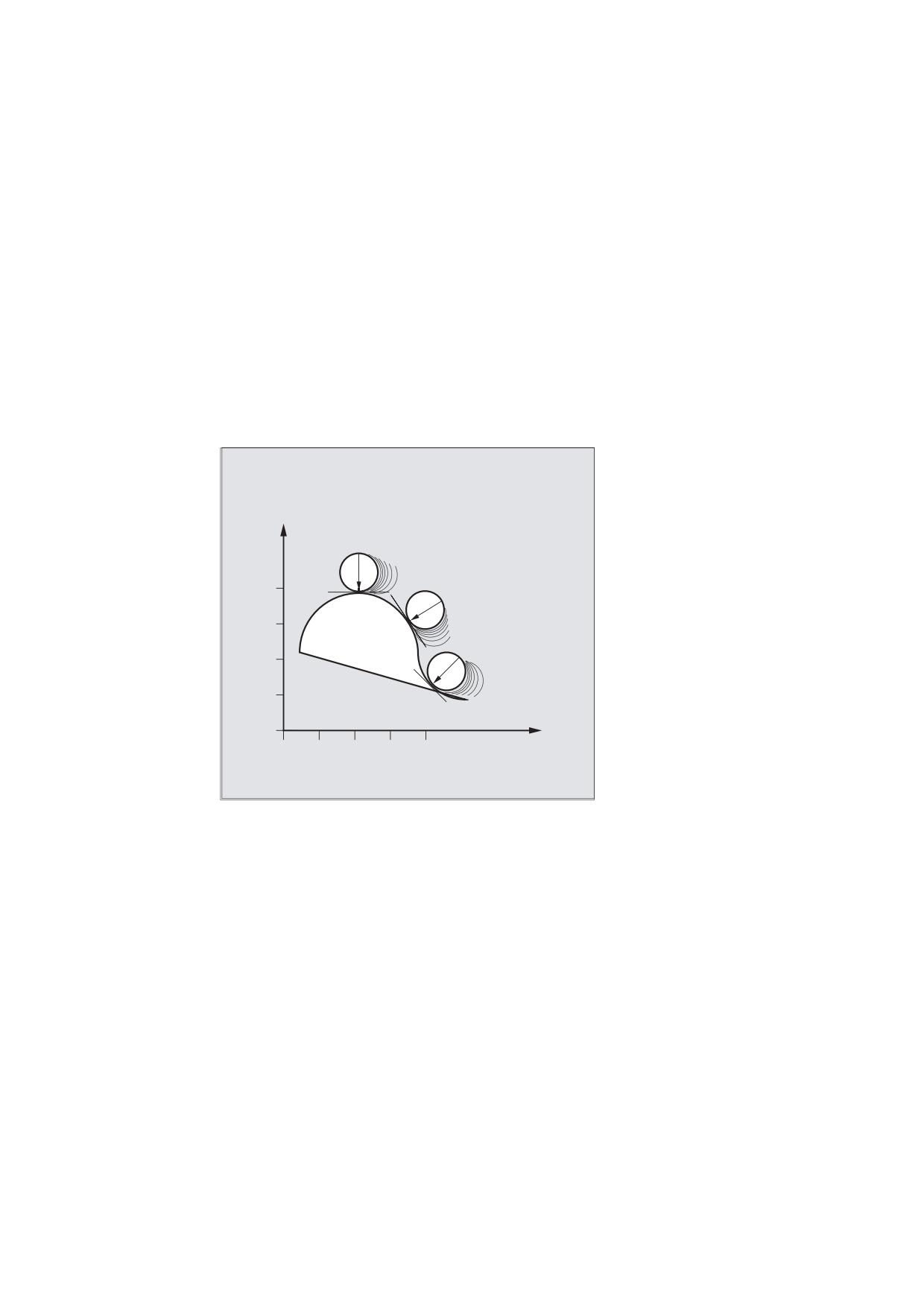
Tangential control (TANG, TANGON, TANGOF, TLIFT, TANGDEL)
Function
The following axis follows the path of the leading axis along the tangent. This allows
alignment of the tool parallel to the contour. Using the angle programmed in the
TANGONinstruction, the tool can be positioned relative to the tangent.
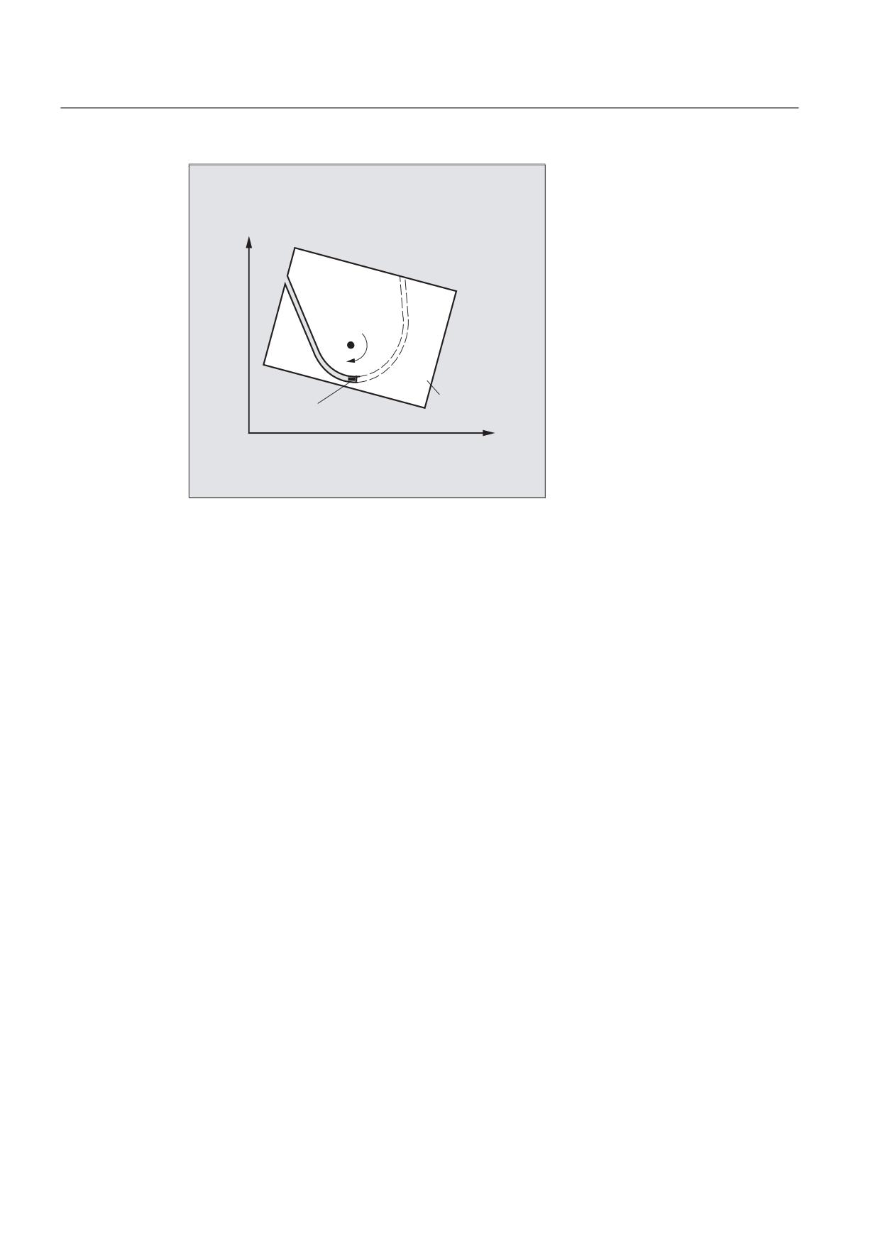
<
;
Application
Tangential control can e.g. be used in the applications:
● Tangential positioning of a rotatable tool during nibbling
● Tracking the workpiece alignment for a bandsaw (see the following diagram).
● Positioning of a dressing tool on a grinding wheel
● Positioning of a cutting wheel for glass or paper working
● Tangential feed of a wire for 5-axis welding.
Job Planning
Programming Manual, 03/2010, 6FC5398-2BP20-1BA0
453
Path traversing behavior
8.1 Tangential control (TANG, TANGON, TANGOF, TLIFT, TANGDEL)
<
:RUNSLHFH
6DZ EDQG
;
Syntax
Defining tangential tracking:
TANG(<Faxis>,<Laxis1>,<Laxis2>,<coupling factor>,<KS>,<Opt>)
Activating tangential control:
TANGON(<Faxis>,<angle>,<Dist>,<angular tolerance>)
Deactivating tangential control:
TANGOF (<Faxis>)
Activating the "Insert intermediate block at contour corners" function:
TLIFT(<Faxis>)
The TLIFT operation is specified after the axis assignment with TANG(...).
Deactivating the "Inserting intermediate block at contour corners" function:
Repeat the TANG(...) operation without a following TLIFT(<Faxis>).
Deleting definition of tangential tracking:
TANGDEL(<Faxis>)
An existing user-defined tangential tracking must be deleted if a new tangential tracking with
the same following axis is defined in the preparation call TANG. Deletion is only possible if the
coupling with TANGOF(<Faxis>) is deactivated.
Meaning
TANG:
Preparatory operation for the definition of tangential tracking
TANGON:
Activate tangential control for the specified following axis
Job Planning
454
Programming Manual, 03/2010, 6FC5398-2BP20-1BA0
Path traversing behavior
8.1 Tangential control (TANG, TANGON, TANGOF, TLIFT, TANGDEL)
TANGOF:
Deactivate tangential control for the specified following axis
TLIFT:
Activate the "Insert intermediate block at contour corners"
function
TANGDEL:
Delete definition of tangential tracking
<Faxis>:
Following axis: additional tangential following rotary axis.
<Laxis1>,<Laxis2>:
Leading axes: path axes, which determine the tangent for
the following axis.
<coupling factor>
:
Coupling factor: Relationship between the angular change
of the tangent and the tracked axis
Default:
1
Note:
A coupling factor of 1 does not have to be programmed
explicitly.
<CS>
:
Identification letter for coordinate system
"B":
Basis coordinate system (Default)
Note:
<CS> = "B" does not have to be explicitly
programmed.
"W":
Workpiece coordinate system (not available)
<Opt>
:
Optimization
"S":
Standard (default)
Note:
<Opt> = "S" does not have to be explicitly
programmed.
"P":
Automatic adaptation of the characteristic over time
of the tangential axis and the contour
Note:
With <Opt> = "P", the dynamic properties of the
following axis are taken into account in the velocity
limitation of the leading axes. This setting is
especially recommended when using kinematic
transformations.
<angle>:
Offset angle of following axis
<Dist>:
Smoothing path of following axis (required for <Opt> = "P")
<angular tolerance>:
Angular tolerance of the following axis (optional; only
evaluated for <Opt> = "P")
Note:
Parameters <Dist> and <Angular tolerance> specifically
limit the error between the tracked axis and the tangent of
the leading axes.
Job Planning
Programming Manual, 03/2010, 6FC5398-2BP20-1BA0
455
Path traversing behavior
8.1 Tangential control (TANG, TANGON, TANGOF, TLIFT, TANGDEL)
Examples
Example 1: Defining and activating tangential tracking
Program code
Comment
N10 TANG(C,X,Y,1,"B","P")
; Definition of a tangential tracking: Rotary
axis C should follow geometry axes X and Y.
N20 TANGON(C,90)
; The C axis is a following axis. On every
movement of the path axes, it is rotated into a
position at 90° to the path tangent.
Note
Simplified programming
TANG(C,X,Y,1,"B","P") can be more simply programmed as TANG(C,X,Y,,,"P").
Example 2: Plane change
Program code
Comment
N10 TANG(A,X,Y,1)
; 1st definition of tangential tracking.
N20 TANGON(A)
; Activating the coupling.
N30 X10 Y20
; Radius
N80 TANGOF(A)
; Deactivate the 1st coupling.
N90 TANGDEL(A)
; Delete the 1st definition.
TANG(A,X,Z)
; 2nd definition of tangential tracking.
TANGON(A)
; Activate the new coupling.
N200 M30
Job Planning
456
Programming Manual, 03/2010, 6FC5398-2BP20-1BA0
Path traversing behavior
8.1 Tangential control (TANG, TANGON, TANGOF, TLIFT, TANGDEL)
Example 3: Geometry axis changeover and TANGDEL
No alarm is produced.
Program code
Comment
N10 GEOAX(2,Y1)
; Y1 is geometry axis 2.
N20 TANG(A,X,Y)
; 1st definition of tangential tracking.
N30 TANGON(A,90)
; Activate tracking with Y1.
N40 G2 F8000 X0 Y0 I0 J50
N50 TANGOF(A)
; Deactivate tracking with Y1.
N60 TANGDEL(A)
; Delete the 1st definition.
N70 GEOAX(2, Y2)
; Y2 is the new geometry axis 2
N80 TANG(A,X,Y)
; 2nd definition of tangential tracking.
N90 TANGON(A,90)
; Activate tracking with Y2.
Example 4: Tangential tracking with automatic optimization
Y1 is geometry axis 2.
Program code
Comment
N80 G0 C0
N100 F=50000
N110 G1 X1000 Y500
N120 TRAORI
N130 G642
; Smoothing and maintaining the
maximum permitted path
deviation:
N171 TRANS X50 Y50
N180 TANG(C,X,Y,1,,"P")
; Definition, tangential
tracking with automatic
optimization of the path
velocity.
N190 TANGON(C,0,5.0,2.0)
; Activating tangential tracking
with automatic optimization:
Smoothing distance, 5 mm
angular tolerance, 2 degrees.
N210 G1 X1310 Y500
N215 G1 X1420 Y500
N220 G3 X1500 Y580 I=AC(1420) J=AC(580)
N230 G1 X1500 Y760
N240 G3 X1360 Y900 I=AC(1360) J=AC(760)
N250 G1 X1000 Y900
N280 TANGOF(C)
N290 TRAFOOF
N300 M02
Job Planning
Programming Manual, 03/2010, 6FC5398-2BP20-1BA0
457
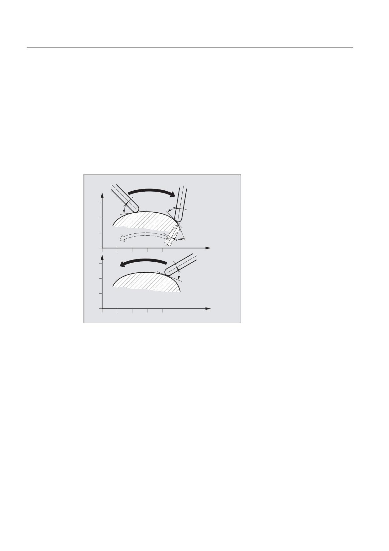
Path traversing behavior
8.1 Tangential control (TANG, TANGON, TANGOF, TLIFT, TANGDEL)
Further information
Defining following axis and leading axis
TANG is used to define the following and leading axes.
A coupling factor specifies the relationship between an angle change on the tangent and the
following axis. Its value is generally 1 (default).
Limit angle using the working area limitation
For path movements, which oscillate back and forth, the tangent jumps through 180° at the
turning point on the path and the orientation of the following axis changes accordingly. This
behavior is generally inappropriate: The return movement should be traversed at the same
negative offset angle as the approach movement:
<
˞
˞
˞
8QZDQWHG UHYHUVH
PRWLRQ
;
<
˞
'HVLUDEOH UHYHUVH
PRWLRQ
;
To do this, limit the working area of the following axis (G25, G26). The working area limit must
be active at the instant of path reversal (WALIMON). If the offset angle lies outside the working
area limit, an attempt is made to return to the permissible working area with the negative
offset angle.
Insert intermediate block at contour corners (TLIFT)
At one corner of the contour the tangent changes and thus the setpoint position of the
following axis. The axis normally tries to compensate this step change at its maximum
possible velocity. However, this causes a deviation from the desired tangential position over
a certain distance on the contour after the corner. If such a deviation is unacceptable for
technological reasons, the instruction TLIFT can be used to force the control to stop at the
corner and to rotate the following axis to the new tangent direction in an automatically
generated intermediate block.
The path axis is used for turning if the following axis has been used once as the path axis. A
maximum axis velocity of the following axis can be achieved with function
TFGREF[<axis>]=0.001.
If the follow-up axis was not previously traversed as a path axis it is now traversed as a
positioning axis. The velocity is then dependent on the positioning velocity in the machine
data.
Job Planning
458
Programming Manual, 03/2010, 6FC5398-2BP20-1BA0
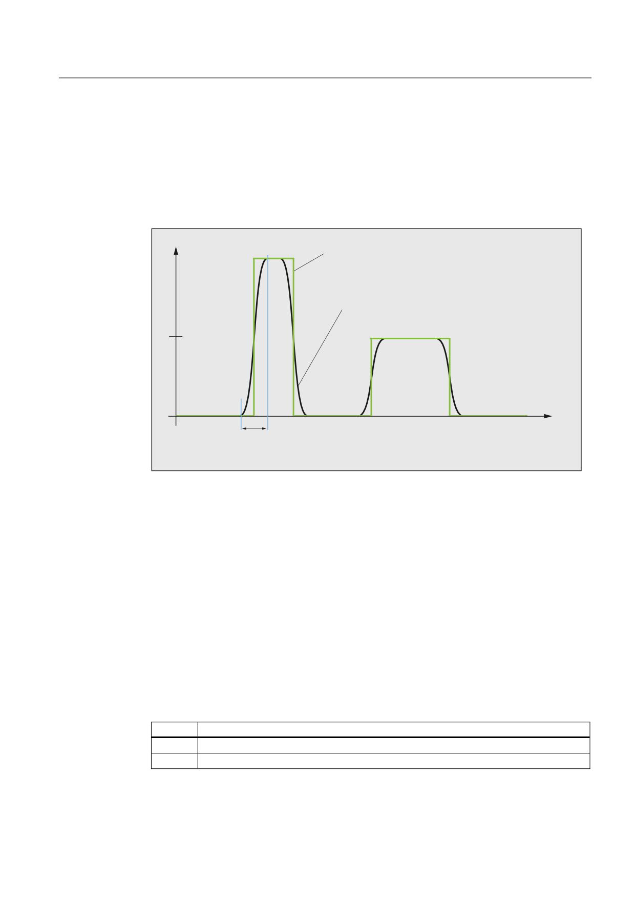
Path traversing behavior
8.1 Tangential control (TANG, TANGON, TANGOF, TLIFT, TANGDEL)
The axis is rotated at its maximum possible velocity.
Optimization possibility
If the automatic optimization is selected (<Opt>="P") and if the parameter smoothing distance
(<Dist>) and angular tolerance (<angular tolerance>) are specified for the following axis,
then for tangential tracking, velocity steps of the slave axis as a result of steps in the leading
axis contour are smoothed. In this case, the following axis is controlled with look ahead (refer
to the diagram) in order to keep the deviation as small as possible.
YF
6HWSRLQW YHORFLW\ SURILOH RI
WUDFNHG D[LV &
6PRRWKHG YHORFLW\ SURILOH
W V
'LVW
1
1
1
1
1
Defining the angle change
The angular change limit at which an intermediate block is automatically inserted is defined
using the following machine data:
MD37400 $MA_EPS_TLIFT_TANG_STEP (Tangent angle for corner recognition)
Effect on transformations
The position of the rotary axis to which follow-up control is applied can act as the input value
for a transformation.
Explicit positioning of the following axis
If an axis, which is following your lead axes, is positioned explicitly the position is added to
the programmed offset angle.
All distance data are permissible (path and positioning axis motion).
Status of coupling
The status of the coupling can be interrogated in the NC part program using the system
variable $AA_COUP_ACT[<axis>]:
Value
Meaning
0
No coupling active
1,2,3
Tangential follow-up active
Job Planning
Programming Manual, 03/2010, 6FC5398-2BP20-1BA0
459
Path traversing behavior
8.2 Feedrate response (FNORM, FLIN, FCUB, FPO)
8.2
Feedrate response (FNORM, FLIN, FCUB, FPO)
Function
To permit flexible definition of the feed characteristic, the feed programming according to
DIN 66205 has been extended by linear and cubic characteristics.
The cubic characteristics can be programmed either directly or as interpolating splines.
These additional characteristics make it possible to program continuously smooth velocity
characteristics depending on the curvature of the workpiece to be machined.
These additional characteristics make it possible to program continuously smooth velocity
characteristics depending on the curvature of the workpiece to be machined.
Syntax
F… FNORM
F… FLIN
F… FCUB
F=FPO(…,…,…)
Significance
FNORM
Basic setting. The feed value is specified as a function of the traverse path
of the block and is then valid as a modal value.
FLIN
Path velocity profile linear:
The feed value is approached linearly via the traverse path from the
current value at the block beginning to the block end and is then valid as a
modal value. The response can be combined with G93 and G94.
FCUB
Path velocity profile cubic:
The blockwise programmed F values (relative to the end of the block) are
connected by a spline. The spline begins and ends tangentially with the
previous and following defined feedrate and takes effect with G93 and
G94.
If the F address is missing from a block, the last F value to be programmed
is used.
F=FPO…
Polynomial path velocity profile:
The F address defines the feed characteristic via a polynomial from the
current value to the block end. The end value is valid thereafter as a modal
value.
Feed optimization on curved path sections
Feed polynomial F=FPO and feed spline FCUB should always be traversed at constant
cutting rate CFC, thereby allowing a jerk-free setpoint feed profile to be generated. This
enables creation of a continuous acceleration setpoint feed profile.
Job Planning
460
Programming Manual, 03/2010, 6FC5398-2BP20-1BA0
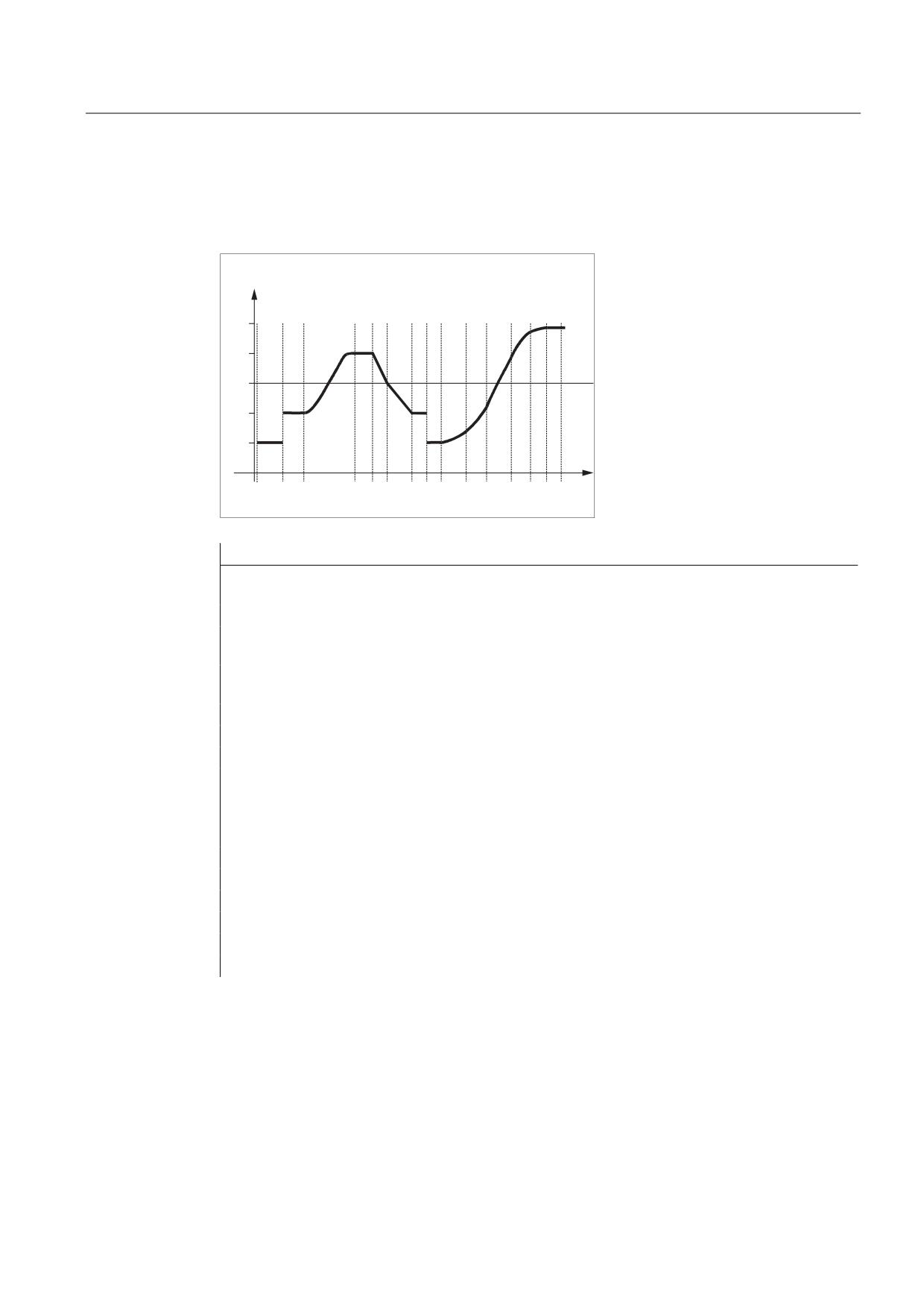
Path traversing behavior
8.2 Feedrate response (FNORM, FLIN, FCUB, FPO)
Example: Various feed profiles
This example shows you the programming and graphic representation of various feed
profiles.
)HHG
3DWK
1
1
1
1 1
1
1 1
1
1
1
1
1 1 1
Program code
Comments
N1 F1000 FNORM G1 X8 G91 G64
; Constant feedrate profile, incremental
dimension data
N2 F2000 X7
; Setpoint velocity step change
N3 F=FPO(4000, 6000, -4000)
; Feed profile via polynomial with feed 4000
at the end of the block
N4 X6
; Polynomial feedrate 4000 is valid as modal
value
N5 F3000 FLIN X5
; Linear feedrate profile
N6 F2000 X8
; Linear feedrate profile
N7 X5
Linear feedrate is valid as modal value
N8 F1000 FNORM X5
; Constant feedrate profile with acceleration
step change
N9 F1400 FCUB X8
; All of the following F values programmed in
blocks are connected with splines
N10 F2200 X6
N11 F3900 X7
N12 F4600 X7
N13 F4900 X5
; Switch-out spline profile
N14 FNORM X5
N15 X20
Job Planning
Programming Manual, 03/2010, 6FC5398-2BP20-1BA0
461
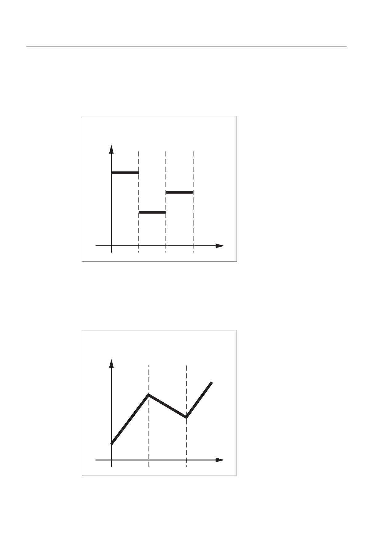
Path traversing behavior
8.2 Feedrate response (FNORM, FLIN, FCUB, FPO)
FNORM
The feed address F defines the path feed as a constant value according to DIN 66025.
Please refer to Programming Manual "Fundamentals" for more detailed information on this
subject.
)HHG
3DWK
FLIN
The feed characteristic is approached linearly from the current feed value to the programmed
F value until the end of the block.
Example:
N30 F1400 FLIN X50
)HHG
3DWK
Job Planning
462
Programming Manual, 03/2010, 6FC5398-2BP20-1BA0
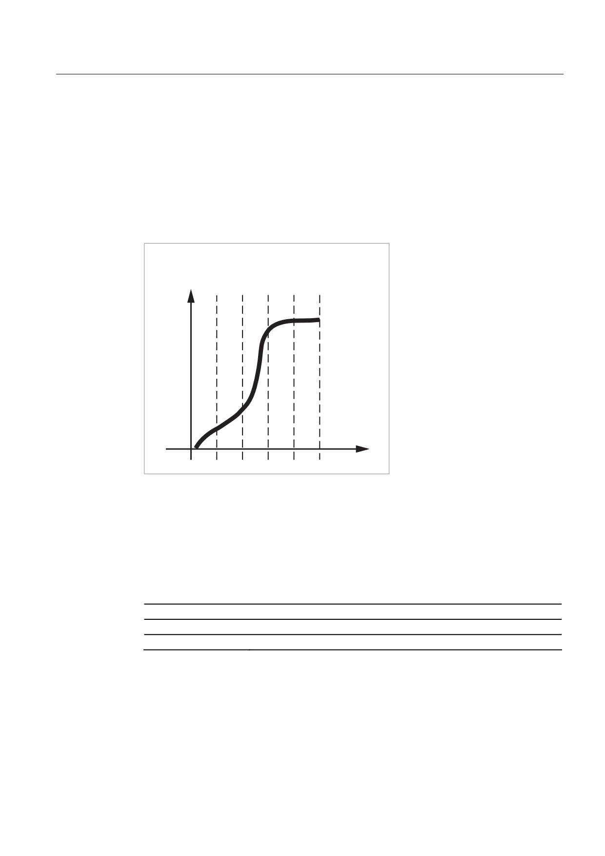
Path traversing behavior
8.2 Feedrate response (FNORM, FLIN, FCUB, FPO)
FCUB
The feed is approached according to a cubic characteristic from the current feed value to the
programmed F value until the end of the block. The control uses splines to connect all the
feed values programmed non-modally that have an active FCUB. The feed values act here
as interpolation points for calculation of the spline interpolation.
Example:
N50 F1400 FCUB X50
N60 F2000 X47
N70 F3800 X52
)HHG
3DWK
F=FPO(…,…,…)
The feed characteristic is programmed directly via a polynomial. The polynomial coefficients
are specified according to the same method used for polynomial interpolation.
Example:
F=FPO(endfeed, quadf, cubf)
endfeed, quadf and cubf are previously defined variables.
endfeed:
Feed at block end
quadf:
Quadratic polynomial coefficient
cubf:
Cubic polynomial coefficient
With an active FCUB, the spline is linked tangentially to the characteristic defined via FPO at the
block beginning and block end.
Job Planning
Programming Manual, 03/2010, 6FC5398-2BP20-1BA0
463
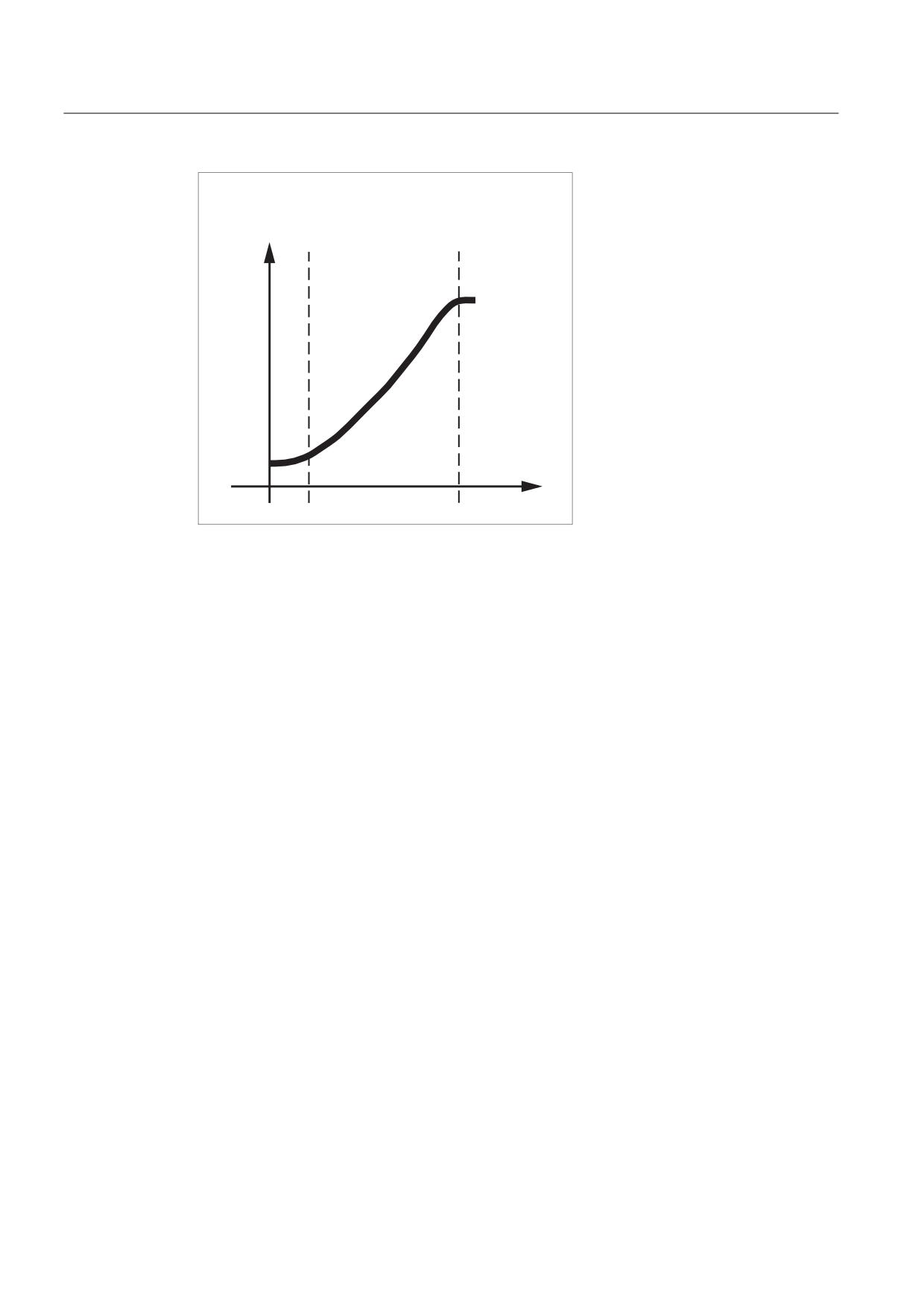
Path traversing behavior
8.2 Feedrate response (FNORM, FLIN, FCUB, FPO)
)HHG
3DWK
Restrictions
The functions for programming the path traversing characteristics apply regardless of the
programmed feed characteristic.
The programmed feed characteristic is always absolute regardless of G90 or G91.
Feed response FLIN and FCUB are active with
G93 and G94.
FLIN and FCUB is not active with
G95, G96/G961 and G97/G971.
Active compressor COMPON
With an active compressor COMPON the following applies when several blocks are joined to
form a spline segment:
FNORM:
The F word of the last block in the group applies to the spline segment.
FLIN:
The F word of the last block in the group applies to the spline segment.
The programmed F value applies until the end of the segment and is then approached
linearly.
FCUB:
The generated feed spline deviates from the programmed end points by an amount not
exceeding the value set in machine data $MC_COMPESS_VELO_TOL.
F=FPO(…,…,…)
These blocks are not compressed.
Job Planning
464
Programming Manual, 03/2010, 6FC5398-2BP20-1BA0
Path traversing behavior
8.3 Program sequence with preprocessing memory (STOPFIFO, STARTFIFO, FIFOCTRL, STOPRE)
8.3
Program sequence with preprocessing memory (STOPFIFO,
STARTFIFO, FIFOCTRL, STOPRE)
Function
Depending on its expansion level, the control system has a certain quantity of so-called
preprocessing memory in which prepared blocks are stored prior to program execution and
then output as high-speed block sequences while machining is in progress. These
sequences allow short paths to be traversed at a high velocity. Provided that there is
sufficient residual control time available, the preprocessing memory is always filled.
3UHSUR
1& SURJUDP
FHVVLQJ
PHPRU\
3URGXFWLRQ SURFHGXUH IDVW EORFN VHTXHQFH
Designate machining step
The beginning and end of the machining step to be buffered in the preprocessing memory
are identified in the part program with STOPFIFO and STARTFIFO respectively. The processing
of the preprocessed and buffered blocks starts only after the STARTFIFO command or if the
preprocessing memory is full.
Automatic preprocessing memory control
Automatic preprocessing memory control is called with the FIFOCTRL command. FIFOCTRL
initially works just like STOPFIFO. Whatever the programming, processing will not start until the
preprocessing memory is full. However, the response to the emptying of the preprocessing
memory does differ: With FIFOCTRL, the path velocity is reduced increasingly once the fill
level reaches 2/3 in order to prevent complete emptying and deceleration to standstill.
Preprocessing stop
Programming the STOPRE command in a block will stop block preprocessing and buffering.
The following block is not executed until all preprocessed and saved blocks have been
executed in full. The preceding block is halted in exact stop (as with G9).
Job Planning
Programming Manual, 03/2010, 6FC5398-2BP20-1BA0
465
Path traversing behavior
8.3 Program sequence with preprocessing memory (STOPFIFO, STARTFIFO, FIFOCTRL, STOPRE)
Syntax
Table 8- 1
Identify machining step:
STOPFIFO
STARTFIFO
Table 8- 2
Automatic preprocessing memory control:
FIFOCTRL
Table 8- 3
Preprocessing stop:
STOPRE
Note
The STOPFIFO, STARTFIFO, FIFOCTRL, and STOPRE commands have to be programmed in a
separate block.
Significance
STOPFIFO:
STOPFIFO identifies the start of a machining step to be buffered in the
preprocessing memory. STOPFIFO stops processing and fills the
preprocessing memory until:
• STARTFIFO or STOPRE is detected
or
• The preprocessing memory is full
or
• The end of the program is reached
STARTFIFO:
STARTFIFO starts rapid processing of the machining step; the
preprocessing memory is filled in parallel to this.
FIFOCTRL:
Activation of automatic preprocessing memory control
STOPRE:
Stop preprocessing
Job Planning
466
Programming Manual, 03/2010, 6FC5398-2BP20-1BA0

Path traversing behavior
8.3 Program sequence with preprocessing memory (STOPFIFO, STARTFIFO, FIFOCTRL, STOPRE)
Note
The preprocessing memory is not filled or filling is interrupted if the machining step contains
commands that require unbuffered operation (search for reference, measuring functions,
etc.).
Note
The control generates an internal preprocessing stop in the event of access to status data
($SA...).
CAUTION
If tool offset or spline interpolations are active, a STOPRE command should not be
programmed, as this will lead to contiguous block sequences being interrupted.
Example: Stop preprocessing
Program code
Comment
N30 MEAW=1 G1 F1000 X100 Y100 Z50
; Measurement block with probe at first
measuring input and linear
interpolation.
N40 STOPRE
; Preprocessing stop.
Job Planning
Programming Manual, 03/2010, 6FC5398-2BP20-1BA0
467
Path traversing behavior
8.4 Conditionally interruptible program sections (DELAYFSTON, DELAYFSTOF)
8.4
Conditionally interruptible program sections (DELAYFSTON,
DELAYFSTOF)
Function
Conditionally interruptible part program sections are called stop delay sections. No stopping
should occur and the feed should not be changed within certain program sections.
Essentially, short program sections - e.g. for machining a thread - should be protected from
almost all stop events. Stops do not take effect until the program section has been
completed.
Syntax
DELAYFSTON
DELAYFSTOF
The commands are programmed separately in a part program line.
Both commands are only permitted in part programs but not in synchronous actions.
Significance
DELAYFSTON
Define a start of a range in which "soft" stops are delayed up to the
end of the stop delay section.
DELAYFSTOF
Define the end of the stop delay section
Note
For machine data MD11550 $MN_STOP_MODE_MASK Bit 0 = 0 (default), a stop delay
section is implicitly defined if G331/G332 is active and a path motion or G4 is programmed.
Example: Stop events
In the stop delay section, a change in the feedrate and feedrate inhibit are ignored. They
only become effective after the stop delay section.
Stop events are divided into:
"Soft" stop events
Response: delayed
"Hard" stop events
Response: immediate
Job Planning
468
Programming Manual, 03/2010, 6FC5398-2BP20-1BA0

Path traversing behavior
8.4 Conditionally interruptible program sections (DELAYFSTON, DELAYFSTOF)
Selection of a number of stop events, which induce at least short stopping:
Event name
Response
interruption parameters
RESET
immediate
IS: DB21,… DBX7.7 and DB11, … DBX20.7
PROG_END
Alarm 16954
NC prog.: M30
INTERRUPT
delayed
IS: FC-9 and ASUP DB10, ... DBB1
SINGLEBLOCKSTOP
delayed
Single block mode in the stop delay section is activated:
NC stops at the end of the first block outside the stop delay
section.
Single block already selected before the stop delay
section:
NST: "NC Stop at block limit" DB21, ... DBX7.2
STOPPROG
delayed
IS: DB21,… DBX7.3 and DB11, … DBX20.5
PROG_STOP
Alarm 16954
NC prog.: M0 and M1
WAITM
Alarm 16954
NC prog.: WAITM
WAITE
Alarm 16954
NC prog.: WAITE
STOP_ALARM
immediate
Alarm: Alarm configuration STOPBYALARM
RETREAT_MOVE_THREAD
Alarm 16954
NC prog.: Alarm 16954 with LFON
(stop and fastlift in G33 not possible)
WAITMC
Alarm 16954
NC prog.: WAITMC
NEWCONF_PREP_STOP
Alarm 16954
NC prog.: NEWCONF
SYSTEM_SHUTDOWN
immediate
System shutdown with 840Di
ESR
delayed
Extended stop and retract
EXT_ZERO_POINT
delayed
External zero offset
STOPRUN
Alarm 16955
OPI: PI "_N_FINDST" STOPRUN
Explanation of the responses
immediate ("hard" stop event)
Stops immediately even in stop delay
section.
delayed ("soft" stop event)
Does not stop (even short-term) until after
stop delay section.
Alarm 16954
Program is aborted because illegal program
commands have been used in stop delay
section.
Alarm 16955
Program is continued, an illegal action has
taken place in the stop delay section.
Alarm 16957
The program section (stop delay section)
enclosed by DELAYFSTON and
DELAYFSTOF could not be activated.
Every stop will take effect immediately in
the section and is not subject to a delay.
For a list of other responses to stop events, see:
References:
Function Manual Basic Functions; Mode Group, Channel, Program Operation, (K1),
"Influencing and Impact on Stop Events"
Job Planning
Programming Manual, 03/2010, 6FC5398-2BP20-1BA0
469
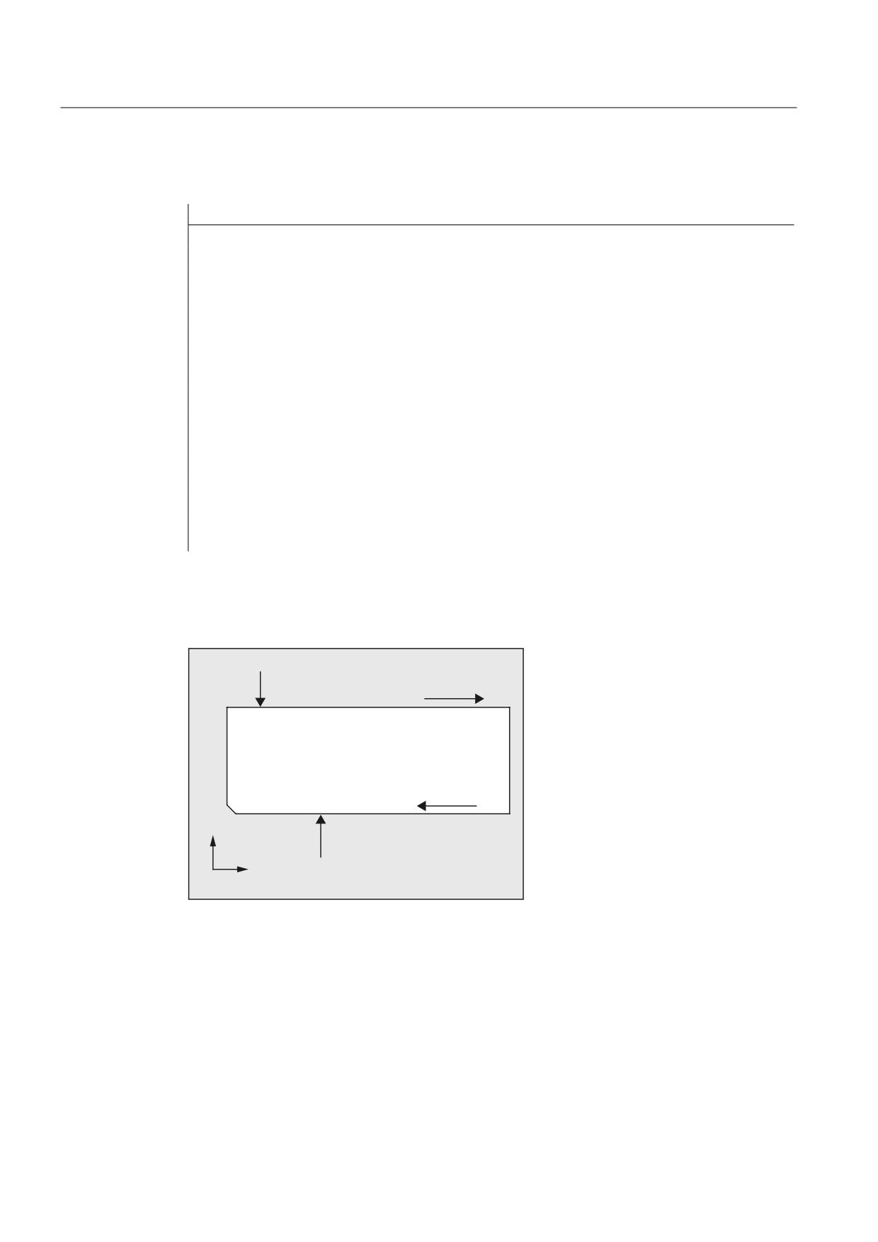
Path traversing behavior
8.4 Conditionally interruptible program sections (DELAYFSTON, DELAYFSTOF)
Example: Nesting stop delay sections in two program levels
Program code
Comments
N10010 DELAYFSTON()
; Blocks with N10xxx program level 1.
N10020 R1 = R1 + 1
N10030 G4 F1
; Stop delay section starts.
N10040 subprogram2
; Interpretation of subprogram 2
N20010 DELAYFSTON()
; Ineffective, repeated start, 2nd level.
N20020 DELAYFSTOF()
; Ineffective, end at another level.
N20030 RET
N10050 DELAYFSTOF()
; Stop delay section end at the same level.
N10060 R2 = R2 + 2
N10070 G4 F1
; Stop delay section ends. From now, stops act
immediately.
Example: Program excerpt
The following program block is repeated in a loop:
1& VWRSV
1
* =
1
* ;
1
* ; =
1
*
=
;
1
*
=
;
6WRS NH\
6WRS NH\ GXULQJ *
PDFKLQLQJ
=
As shown in the diagram, the user presses "Stop" in the stop delay section and the NC starts
deceleration outside the stop delay section, i.e., in block N100. That causes the NC to stop at
the beginning of N100.
Job Planning
470
Programming Manual, 03/2010, 6FC5398-2BP20-1BA0
Path traversing behavior
8.4 Conditionally interruptible program sections (DELAYFSTON, DELAYFSTOF)
Program code
Comments
N99 MY_LOOP:
N100 G0 Z200
N200 G0 X0 Z200
N300 DELAYFSTON()
N400 G33 Z5 K2 M3 S1000
N500 G33 Z0 X5 K3
N600 G0 X100
N700 DELAYFSTOF()
N800 GOTOB MY_LOOP
Details on SERUPRO type block searches and feeds in conjunction with G331/G332 Feed for
tapping without compensating chuck, see:
References:
Function Manual Basic Functions; Mode Group, Channel, Program Operation (K1)
Function Manual Basic Functions; Feedrates (V1)
Advantages of the stop delay section
A program section is processed without a drop in velocity.
If the user aborts the program after a stop with RESET, the aborted program block is after
the protected section. This program block is a suitable search target for a subsequent block
search.
The following main run axes are not stopped as long as a stop delay section is in progress:
● Command axes and
● Positioning axes that travel with POSA
Parts program command G4 is permitted in a stop delay section whereas other parts program
commands that cause a temporary stop (e.g., WAITM) are not permitted.
Like a path movement, G4 activates the stop delay section and/or keeps it active.
Example: Feedrate intervention
If the override is reduced to 6% before a stop delay section, the override becomes active in
the stop delay section.
If the override is reduced from 100% to 6% in the stop delay section, the stop delay section
is completed with 100% and beyond that the program continues with 6%.
The feed disable has no effect in the stop delay section; the program does not stop until after
the stop delay section.
Job Planning
Programming Manual, 03/2010, 6FC5398-2BP20-1BA0
471
Path traversing behavior
8.4 Conditionally interruptible program sections (DELAYFSTON, DELAYFSTOF)
Overlapping/nesting
If two stop delay sections overlap, one from the NC commands and the other from machine
data MD 11550: STOP_MODE_MASK, the largest possible stop delay section will be generated.
The following features regulate the interaction between NC commands DELAYFSTON and
DELAYFSTOF with nesting and end of subroutine:
1. DELAYFSTOF is activated implicitly at the end of the subroutine in which DELAYFSTON is
called.
2. DELAYFSTON stop delay section has no effect.
3. If subroutine 1 calls subroutine 2 in a stop delay section, the whole of subroutine 2 is a
stop delay section. DELAYFSTOF in particular has no effect in subroutine 2.
Note
REPOSA is an end of subroutine command and DELAYFSTON is always deselected.
If a "hard" stop event coincides with the "stop delay section", the entire "stop delay
section" is deselected! Thus, if any other stop occurs in this program section, it will be
stopped immediately. A new program setting (new DELAYFSTON) must be made in order to
start a new stop delay section.
If the Stop key is pressed before the stop delay section and the NCK must travel into the
stop delay section for braking, the NCK will stop in the stop delay section and the stop
delay section will remain deselected!
A stop delay section entered with an override of 0% will not be accepted!
This applies to all "soft" stop events.
STOPALL can be used to decelerate in the stop delay section. A STOPALL, however,
immediately activates all other stop events that were previously delayed.
System variables
A stop delay section can be detected in the parts program with $P_DELAYFST. If bit 0 of the
system variables is set to 1, parts program processing is now in a stop delay section.
A stop delay section can be detected in synchronized actions with $AC_DELAYFST. If bit 0 of
the system variables is set to 1, parts program processing is now in a stop delay section.
Compatibility
Default of machine data MD 11550: STOP_MODE_MASK Bit 0 = 0 triggers implicit stop delay
section during a G code group G331/G332 and when a path movement or G4 is programmed.
Bit 0 = 1 permits a stop during a G code group G331/G332 and when a path movement or G4
has been programmed (behavior until SW 6). The DELAYFSTON/DELAYFSTOF commands must
be used to define a stop delay section.
Job Planning
472
Programming Manual, 03/2010, 6FC5398-2BP20-1BA0
Path traversing behavior
8.5 Preventing program position for SERUPRO (IPTRLOCK, IPTRUNLOCK)
8.5
Preventing program position for SERUPRO (IPTRLOCK,
IPTRUNLOCK)
Function
For some complicated mechanical situations on the machine it is necessary to the stop block
search SERUPRO.
By using a programmable interruption pointer it is possible to intervene before an
untraceable point with "Search at point of interruption".
It is also possible to define untraceable sections in part program sections that the NCK
cannot yet re-enter. When the program is interrupted, the NCK notes the last block that was
processed that can then be searched for via the HMI operator interface.
Syntax
IPTRLOCK
IPTRUNLOCK
The commands are located in a part program line and allow a programmable interruption
pointer
Significance
IPTRLOCK
Start of untraceable program section
IPTRUNLOCK
End of untraceable program section
Both commands are only permitted in part programs, but not in synchronous actions.
Job Planning
Programming Manual, 03/2010, 6FC5398-2BP20-1BA0
473
Path traversing behavior
8.5 Preventing program position for SERUPRO (IPTRLOCK, IPTRUNLOCK)
Example
Nesting of untraceable program sections in two program levels with implicit IPTRUNLOCK.
Implicit IPTRUNLOCK in subprogram 1 ends the untraceable section.
Program code
Comment
N10010 IPTRLOCK()
N10020 R1 = R1 + 1
N10030 G4 F1
; Hold block of the search-suppressed program
section starts.
N10040 subprogram2
; Interpretation of subprogram 2
N20010 IPTRLOCK ()
; Ineffective, repeated start.
N20020 IPTRUNLOCK ()
; Ineffective, end at another level.
N20030 RET
N10060 R2 = R2 + 2
N10070 RET
; End of search-suppressed program section.
N100 G4 F2
; Main program is continued.
The interruption pointer then produces an interruption at 100 again.
Acquiring and finding untraceable sections
Non-searchable program sections are identified with language commands IPTRLOCK and
IPTRUNLOCK .
Command IPTRLOCK freezes the interruption pointer at a single block executable in the main
run (SBL1). This block will be referred to as the hold block below. If the program is aborted
after IPTRLOCK, this hold block can be searched for from the HMI user interface.
Continuing from the current block
The interruption pointer is placed on the current block with IPTRUNLOCK as the interruption
point for the following program section.
Once the search target is found a new search target can be repeated with the hold block.
An interrupt pointer edited by the user must be removed again via the HMI.
Job Planning
474
Programming Manual, 03/2010, 6FC5398-2BP20-1BA0