SINUMERIK 840D sl/828D. Job Planning. Programming Manual (2010-2018) - page 19
Transformations
6.2 Three, four and five axis transformation (TRAORI)
Parameter
ORIPLANE
Interpolation in the plane (large-radius circular interpolation)
ORICONCW
Interpolation on the peripheral surface of a taper in the
clockwise direction
ORICONCCW
Interpolation on the peripheral surface of a taper in the
counterclockwise direction
ORICONTO
Interpolation on the peripheral surface of a taper with
tangential transition
A6= B6= C6=
Programming of a rotary axis of the taper (normalized vector)
NUT=angle
Opening angle of taper in degrees
NUT=+179
Traverse angle smaller than or equal to 180 degrees
NUT=-181
Traverse angle greater than or equal to 180 degrees
ORICONIO
Interpolation on the peripheral surface of a taper
A7= B7= C7=
Intermediate orientation (programming as normalized vector)
PHI
Angle of rotation of the orientation about the direction axis of
the taper
PSI
Opening angle of the taper
Possible polynomials
Apart from the different angles, polynomials can also be
PO[PHI]=(a2, a3, a4, a5)
programmed up to the 5th degree
PO[PSI]=(b2, b3, b4, b5)
Example of different changes to orientation
…
N10 G1 X0 Y0 F5000
N20 TRAORI(1)
; Orientation transformation on.
N30 ORIVECT
; Interpolate tool orientation as a vector.
…
; Tool orientation in the plane.
N40 ORIPLANE
; Select large-radius circular interpolation.
N50 A3=0 B3=0 C3=1
N60 A3=0 B3=1 C3=1
; Orientation in the Y/Z plane is rotated
through 45 degrees, orientation (0,1, 2,1/√2,
1/√2) is reached at the end of the block.
…
N70 ORICONCW
; Orientation programming on the outside of the
taper:
N80 A6=0 B6=0 C6=1 A3=0 B3=0 C3=1
; The orientation vector is interpolated on the
outside of a taper with the direction (0,0,1)
up to the orientation (1/√2,0,1/√2) in the
clockwise sense, the angle of rotation is
270 degrees.
N90 A6=0 B6=0 C6=1
; The tool orientation goes through a full
revolution on the outside of the same taper.
Job Planning
Programming Manual, 03/2010, 6FC5398-2BP20-1BA0
337
Transformations
6.2 Three, four and five axis transformation (TRAORI)
Description
If changes of orientation along the peripheral surface of a taper anywhere in space are to be
described, the vector about which the tool orientation is to be rotated must be known. The
start and end orientation must also be specified. The start orientation results from the
previous block and the end orientation has to be programmed or defined via other
conditions.
Programming in the ORIPLANE plane corresponds to ORIVECT
The programming of large-radius circular interpolation together with angle polynomials
corresponds to the linear and polynomial interpolation of contours. The tool orientation is
interpolated in a plane that is defined by the start and end orientation. If additional
polynomials are programmed, the orientation vector can also be tilted out of the plane.
Programming of circles in a plane G2/G3, CIP and CT
The extended orientation corresponds to the interpolation of circles in a plane. For the
corresponding programming options for circles with centers or radii such as G2/G3, circle via
intermediate point CIP and tangential circles CT, see
References: Programming Manual Fundamentals, "Programming motion commands".
Orientation programming
Interpolation of the orientation vector on the peripheral surface of a taper ORICONxx
Four different types of interpolation from G-code group 51 can be selected for interpolating
orientations on the peripheral surface of a taper:
1. Interpolation on the outside of a taper in the clockwise direction ORICONCW with
specification of end orientation and taper direction, or opening angle. The direction vector
is programmed with identifiers A6, B6, C6 and the opening angle of the taper with
identifier NUT= value range in interval 0 degrees to 180 degrees.
2. Interpolation on the outside of a taper in the counterclockwise direction ORICONCCW with
specification of end orientation and taper direction, or opening angle. The direction vector
is programmed with identifiers A6, B6, C6 and the opening angle of the taper with
identifier NUT= value range in interval 0 degrees to 180 degrees.
3. Interpolation on the outside of a taper ORICONIO with specification of end orientation and
an intermediate orientation, which is programmed with identifiers A7, B7, C7.
4. Interpolation on the outside of a taper ORICONTO with tangential transition and specification
of end orientation. The direction vector is programmed with identifiers A6, B6, C6.
Job Planning
338
Programming Manual, 03/2010, 6FC5398-2BP20-1BA0
Transformations
6.2 Three, four and five axis transformation (TRAORI)
6.2.9
Specification of orientation for two contact points (ORICURVE, PO[XH]=,
PO[YH]=, PO[ZH]=)
Function
Programming the change in orientation using the second curve in space ORICURVE
Another way to program changes in orientation, besides using the tool tip along a curve in
space, is to program the motion of a second contact point of the tool using ORICURVE. In this
way, changes in tool orientation can be defined uniquely, as when programming the tool
vector itself.
Machine manufacturer
Please refer to the machine manufacturer's notes on axis identifiers that can be set via
machine data for programming the second orientation path of the tool.
Programming
This type of interpolation can be used to program points (using G1) or polynomials (using
POLY) for the two curves in space. Circles and involutes are not permitted. A BSPLINE spline
interpolation and the "Combine short spline blocks" function can also be activated.
References:
/FB1/ Function Manual, Basic Functions; Continuous-Path Mode, Exact Stop, Look Ahead
(B1), chapter: Combine short spline blocks
The other spline types, ASPLINE and CSPLINE, and compressor activation using COMPON,
COMPCURV or COMPCAD are not permitted.
The motion of the two contact points of the tool can be predefined up to the 5th degree when
programming the orientation polynomials for coordinates.
Extended orientation interpolation with additional curve in space and polynomials for
coordinates
N... ORICURVE
Specification of the motion of the second
N... PO[XH]=(xe, x2, x3, x4, x5)
contact point of the tool and additional
N... PO[YH]=(ye, y2, y3, y4, y5)
N... PO[ZH]=(ze, z2, z3, z4, z5)
polynomials of the coordinates in
question
Job Planning
Programming Manual, 03/2010, 6FC5398-2BP20-1BA0
339
Transformations
6.2 Three, four and five axis transformation (TRAORI)
Parameters
ORICURVE
Interpolation of the orientation specifying a movement
between two contact points of the tool
XH YH ZH
Identifiers of the coordinates of the second contact
point of the tool of the additional contour as a curve
in space
Possible polynomials
Apart from using the appropriate end points, the curves
PO[XH]=(xe, x2, x3, x4,
in space can also be programmed using polynomials.
x5) PO[YH]=(ye, y2, y3,
y4, y5) PO[ZH]=(ze, z2,
z3, z4, z5)
xe, ye, ze
End points of the curve in space
xi, yi, zi
Coefficients of the polynomials up to the 5th degree
Note
Identifiers XH YH ZH for programming a second orientation path
The identifiers must be selected such that no conflict arises with the other identifiers or linear
axes
X Y Z axes
and rotary axes such as
A2 B2 C2 Euler angle or RPY angle
A3 B3 C3 direction vectors
A4 B4 C4 or A5 B5 C5 surface normal vectors
A6 B6 C6 rotation vectors or A7 B7 C7 intermediate point coordinates
or other interpolation parameters.
Job Planning
340
Programming Manual, 03/2010, 6FC5398-2BP20-1BA0
Transformations
6.3 Orientation polynomials (PO[angle], PO[coordinate])
6.3
Orientation polynomials (PO[angle], PO[coordinate])
Function
Irrespective of the polynomial interpolation from G-code group 1 that is currently active, two
different types of orientation polynomial can be programmed up to the 5th degree for a 3-axis
to 5-axis transformation.
1. Polynomials for angles: lead angle LEAD, tilt angle TILT
in relation to the plane that is defined by the start and end orientation.
2. Polynomials for coordinates: XH, YH, ZH of the second curve in space for the tool
orientation of a reference point on the tool.
With a 6-axis transformation, the rotation of rotation vector THT can be programmed with
polynomials up to the 5th degree for rotations of the tool itself, in addition to the tool
orientation.
Syntax
Type 1 orientation polynomials for angles
N… PO[PHI]=(a2, a3, a4, a5)
3-axis to 5-axis transformation
N… PO[PSI]=(b2, b3, b4, b5)
3-axis to 5-axis transformation
Type 2 orientation polynomials for coordinates
N… PO[XH]=(xe, x2, x3, x4, x5)
Identifiers for the coordinates of the second
N… PO[YH]=(ye, y2, y3, y4, y5)
orientation path for tool orientation
N… PO[ZH]=(ze, z2, z3, z4, z5)
In both cases, with 6-axis transformations, a polynomial can also be programmed for the
rotation using
N… PO[THT]=(c2, c3, c4, c5)
Interpolation of the rotation relative to the
or
path
N… PO[THT]=(d2, d3, d4, d5)
Interpolation absolute, relative and
tangential to the change of orientation
of the orientation vector. This is possible if the transformation supports a rotation vector with
an offset that can be programmed and interpolated using the THETA angle of rotation.
Job Planning
Programming Manual, 03/2010, 6FC5398-2BP20-1BA0
341
Transformations
6.3 Orientation polynomials (PO[angle], PO[coordinate])
Meaning
PO[PHI]
Angle in the plane between start and end orientation
PO[PSI]
Angle describing the tilt of the orientation from the plane between start and end
orientation
PO[THT]
Angle of rotation created by rotating the rotation vector of one of the G codes
of group 54 that is programmed using THETA
PHI
Lead angle LEAD
PSI
Tilt angle TILT
THETA
Rotation about the tool direction in Z
PO[XH]
X coordinate of the reference point on the tool
PO[YH]
Y coordinate of the reference point on the tool
PO[ZH]
Z coordinate of the reference point on the tool
Description
Orientation polynomials cannot be programmed:
● If ASPLINE, BSPLINE, CSPLINE spline interpolations are active.
Type 1 polynomials for orientation angles are possible for every type of interpolation
except spline interpolation, that is, linear interpolation with rapid traverse G00 or with
feedrate G01
with polynomial interpolation using POLY and
circular/involute interpolation G02, G03, CIP, CT, INVCW and INCCCW.
However, type 2 polynomials for orientation coordinates are only possible if
linear interpolation with rapid traverse G00 or with feedrate G01 or
polynomial interpolation with POLY is active.
● If the orientation is interpolated using ORIAXES axis interpolation. In this case, polynomials
can be programmed directly with PO[A] and PO[B] for orientation axes A and B.
Type 1 orientation polynomials with ORIVECT, ORIPLANE and ORICONxx
Only type 1 orientation polynomials are possible for large-radius circular interpolation and
interpolation outside of the taper with ORIVECT, ORIPLANE and ORICONxx.
Type 2 orientation polynomials with ORICURVE
If interpolation with the additional curve in space ORICURVE is active, the Cartesian
components of the orientation vector are interpolated and only type 2 orientation polynomials
are possible.
Job Planning
342
Programming Manual, 03/2010, 6FC5398-2BP20-1BA0
Transformations
6.4 Rotations of the tool orientation (ORIROTA, ORIROTR, ORIROTT, ORIROTC, THETA)
6.4
Rotations of the tool orientation (ORIROTA, ORIROTR, ORIROTT,
ORIROTC, THETA)
Function
If you also want to be able to change the orientation of the tools on machine types with
movable tools, program each block with end orientation. Depending on the machine
kinematics you can either program the orientation direction of the orientation axes or the
direction of rotation of orientation vector THETA. Different interpolation types can be
programmed for these rotation vectors:
● ORIROTA: Angle of rotation to an absolute direction of rotation.
● ORIROTR: Angle of rotation relative to the plane between the start and end orientation.
● ORIROTT: Angle of rotation relative to the change in the orientation vector.
● ORIROTC: Tangential angle of rotation to the path tangent.
Syntax
Only if interpolation type ORIROTA is active can the angle of rotation or rotation vector be
programmed in all four modes as follows:
1. Directly as rotary axis positions A, B, C
2. Euler angles (in degrees) with A2, B2, C2
3. RPY angles (in degrees) with A2, B2, C2
4. Direction vector via A3, B3, C3 (angle of rotation using THETA=value)
If ORIROTR or ORIROTT is active, the angle of rotation can only be programmed directly with
THETA.
A rotation can also be programmed in a separate block without an orientation change taking
place. In this case, ORIROTR and ORIROTT are irrelevant. In this case, the angle of rotation is
always interpreted with reference to the absolute direction (ORIROTA).
N... ORIROTA
Define the interpolation of the rotation vector
N... ORIROTR
N... ORIROTT
N... ORIROTC
N... A3= B3= C3= THETA=value
Define the rotation of the orientation vector
N... PO[THT]=(d2, d3, d4, d5)
Interpolate angle of rotation with a 5th order
polynomial
Job Planning
Programming Manual, 03/2010, 6FC5398-2BP20-1BA0
343
Transformations
6.4 Rotations of the tool orientation (ORIROTA, ORIROTR, ORIROTT, ORIROTC, THETA)
Significance
ORIROTA
Angle of rotation to an absolute direction of rotation.
ORIROTR
Angle of rotation relative to the plane between the start and end
orientation.
ORIROTT
Angle of rotation as a tangential rotation vector to the change of orientation
ORIROTC
Angle of rotation as a tangential rotation vector to the path tangent
THETA
Rotation of the orientation vector
THETA=value
Angle of rotation in degrees reached by the end of the block
THETA=Θe
Angle of rotation with end angle Θe of rotation vector
THETA=AC(...)
Non-modal switchover to absolute dimensions
THETA=AC(…)
Non-modal switchover to incremental dimensions
Θe
End angle of rotational vector both absolute with G90 and relative with
G91 (incremental dimensioning) is active
PO[THT]=(
) Polynomial for angle of rotation
Example of rotations of orientations
Program code
Comments
N10 TRAORI
; Activate orientation transformation
N20 G1 X0 Y0 Z0 F5000
; Tool orientation
N30 A3=0 B3=0 C3=1 THETA=0
; In Z direction with angle of rotation 0
N40 A3=1 B3=0 C3=0 THETA=90
; In X direction and rotation about 90 degrees
N50 A3=0 B3=1 C3=0 PO[THT]=(180,90)
; Orientation
N60 A3=0 B3=1 C3=0 THETA=IC(-90)
; In Y direction and rotation about 180
degrees
N70 ORIROTT
; Remains constant and rotation to 90 degrees
N80 A3=1 B3=0 C3=0 THETA=30
; Angle of rotation relative to change of
orientation
; Rotation vector in angle 30 degrees to X/Y
plane
When interpolating block
N40, the angle of rotation from initial value of 0 degrees to final value of 90 degrees is
interpolated linearly. In block N50, the angle of rotation changes from 90 degrees to 180
degrees, according to
parabola θ(u) = +90u2. In N60, a rotation can also be executed without a change in
orientation taking place.
With N80, the tool orientation is rotated from the Y direction toward the X direction. The
change in orientation takes place in the X/Y plane and the rotation vector describes an angle
of 30 degrees to this plane.
Job Planning
344
Programming Manual, 03/2010, 6FC5398-2BP20-1BA0
Transformations
6.4 Rotations of the tool orientation (ORIROTA, ORIROTR, ORIROTT, ORIROTC, THETA)
Description
ORIROTA
The angle of rotation THETA is interpolated with reference to an absolute direction in space.
The basic direction of rotation is defined in the machine data.
ORIROTR
The angle of rotation THETA is interpreted relative to the plane defined by the start and end
orientation.
ORIROTT
The angle of rotation THETA is interpreted relative to the change in orientation. For THETA=0
the rotation vector is interpolated tangentially to the change in orientation and only differs
from ORIROTR if at least one polynomial has been programmed for "tilt angle PSI" for the
orientation. The result is a change in orientation that is not executed in the plane. An
additional angle of rotation THETA can then be used to interpolate the rotation vector such that
it always produces a specific value referred to the change in orientation.
ORIROTC
The rotation vector is interpolated relative to the path tangent with an offset that can be
programmed using the THETA angle. A polynomial PO[THT]=(c2, c3, c4, c5) up to the 5th
degree can also be programmed for the offset angle.
Job Planning
Programming Manual, 03/2010, 6FC5398-2BP20-1BA0
345
Transformations
6.5 Orientations relative to the path
6.5
Orientations relative to the path
6.5.1
Orientation types relative to the path
Function
By using this expanded function, relative orientation is not only achieved at the end of the
block, but across the entire trajectory. The orientation achieved in the previous block is
transferred to the programmed end orientation using large-radius circular interpolation. There
are basically two ways of programming the desired orientation relative to the path:
1. Like the tool rotation, the tool orientation is interpolated relative to the path using
ORIPATH, ORPATHTS.
2. The orientation vector is programmed and interpolated in the usual manner. The rotation
of the orientation vector is initiated relative to the path tangent using ORIROTC.
Syntax
The type of interpolation of the orientation and the rotation of the tool is programmed using:
N... ORIPATH
Orientation relative to the path
N... ORIPATHS
Orientation relative to the path with smoothing of
orientation characteristic
N... ORIROTC
Interpolation of the rotation vector relative to the
path
An orientation blip caused by a corner on the trajectory can be smoothed using ORIPATHS.
The direction and path length of the retracting movement is programmed via the vector using
the components A8=X, B8=Y C8=Z.
Job Planning
346
Programming Manual, 03/2010, 6FC5398-2BP20-1BA0
Transformations
6.5 Orientations relative to the path
ORIPATH/ORIPATHS can be used to program various references to the path tangent via the
three angles
● LEAD= Specification of lead angle relative to the path and surface
● TILT= Specification of tilt angle relative to the path and surface
● THETA= Angle of rotation
for the entire trajectory. Polynomials up to the 5th degree can be programmed in addition to
the THETA angle of rotation using PO[THT]=(...).
Note
Machine manufacturer
Please refer to the machine manufacturer's instructions. Other settings can be made for
orientations relative to the path via configurable machine and setting data. For more detailed
information, please refer to
References:
/FB3/ Function Manual, Special Functions; 3 to 5-Axis Transformation (F2),
Chapter "Orientation"
Significance
Various settings can be made for the interpolation of angles LEAD and TILT via machine data:
● The tool-orientation reference programmed using LEAD and TILT is retained for the entire
block.
● Lead angle LEAD: rotation about the direction vertical to the tangent and normal vector
TILT: rotation of the orientation about the normal vector.
● Lead angle LEAD: rotation about the direction vertical to the tangent and normal vector Tilt
angle TILT: rotation of the orientation in the direction of the path tangent.
● Angle of rotation THETA: rotation of the tool about itself with an additional third rotary axis
acting as an orientation axis in 6-axis transformation.
Note
Orientation relative to the path not permitted in conjunction with OSC, OSS, OSSE, OSD
and OST
Orientation interpolation relative to the path, that is ORIPATH or ORIPATHS and ORIOTC,
cannot be programmed in conjunction with orientation characteristic smoothing with a G
code from group 34. OSOF has to be active for this.
Job Planning
Programming Manual, 03/2010, 6FC5398-2BP20-1BA0
347
Transformations
6.5 Orientations relative to the path
6.5.2
Rotation of the tool orientation relative to the path (ORIPATH, ORIPATHS,
angle of rotation)
Function
With a 6-axis transformation, the tool can be rotated about itself with a third rotary axis to
orientate the tool as desired in space. With a rotation of the tool orientation relative to the
path using ORIPATH or ORIPATHS, the additional rotation can be programmed via the
THETA angle of rotation. Alternatively, the LEAD and TILT angles can be programmed using
a vector, which is located in the plane vertical to the tool direction.
Machine manufacturer
Please refer to the machine manufacturer's instructions. The interpolation of the LEAD and
TILT angles can be set differently using machine data.
Syntax
Rotation of tool orientation and tool
The type of tool orientation relative to the path is activated using ORIPATH or ORIPATHS.
N... ORIPATH
Activate type of orientation relative to the path
N... ORIPATHS
Activate type of orientation relative to the path
with smoothing of the orientation characteristic
Activating the three angles that can be rotated:
N... LEAD=
Angle for the programmed orientation relative to
the surface normal vector
N... TILT=
Angle for the programmed orientation in the
plane, vertical to the path tangent relative to the
surface normal vector
N... THETA=
Angle of rotation relative to the change of
orientation in the tool direction of the third rotary
axis
The values of the angles at the end of block are programmed using LEAD=value, TILT=value
or THETA=value. In addition to the constant angles, polynomials can be programmed for all
three angles up to the 5th degree.
N... PO[PHI]=(a2, a3, a4, a5)
Polynomial for the leading angle LEAD
N... PO[PSI]=(b2, b3, b4, b5)
Polynomial for the tilt angle TILT
N... PO[THT]=(d2, d3, d4, d5)
Polynomial for the angle of rotation
THETA
The higher polynomial coefficients, which are zero, can be omitted when programming.
Example: PO[PHI]=a2 results in a parabola for the LEAD angle.
Job Planning
348
Programming Manual, 03/2010, 6FC5398-2BP20-1BA0
Transformations
6.5 Orientations relative to the path
Significance
Tool orientation relative to the path
ORIPATH Tool orientation in relation to path
ORIPATHS Tool orientation relative to the path; blip in orientation characteristic is
smoothed
LEAD
Angle relative to the surface normal vector in the plane that is defined by the
path tangent and the surface normal vector
TILT
Rotation of orientation in the Z direction or rotation about the path tangent
THETA
Rotation about the tool direction toward Z
PO[PHI] Orientation polynomial for the LEAD angle
PO[PSI] Orientation polynomial for the TILT angle
PO[THT] Orientation polynomial for the THETA angle of rotation
Note
Angle of rotation THETA
A 6-axis transformation is required to rotate a tool with a third rotary axis that acts as an
orientation axis about itself.
6.5.3
Interpolation of the tool rotation relative to the path (ORIROTC, THETA)
Function
Interpolation with rotation vectors
The rotation vector of the tool rotation, programmed with ORIROTC, relative to the path
tangent can also be interpolated with an offset that can be programmed using the THETA
angle of rotation. A polynomial can, therefore, be programmed up to the 5th degree for the
offset angle using PO[THT].
Syntax
N... ORIROTC
Initiate the rotation of the tool relative
to the path tangent
N... A3= B3= C3= THETA=value
Define the rotation of the orientation
vector
N... A3= B3= C3= PO[THT]=(c2, c3, c4, c5)
Interpolate offset angle with
polynomial up to 5th degree
A rotation can also be programmed in a separate block without an orientation change taking
place.
Job Planning
Programming Manual, 03/2010, 6FC5398-2BP20-1BA0
349
Transformations
6.5 Orientations relative to the path
Significance
Interpolation of the rotation of tool relative to the path in 6-axis transformation
ORIROTC
Initiate tangential rotation vector relative to path tangent
THETA=value
Angle of rotation in degrees reached by the end of the block
THETA=θe
Angle of rotation with end angle Θe of rotation vector
THETA=AC(…)
Switch over to absolute dimensions per block
THETA=IC(…)
Switch over to incremental dimensions per block
PO[THT]=(c2, c3, c4, c5) Interpolate offset angle with polynomial of 5th degree
Note
Interpolation of the rotation vector ORIROTC
Initiating rotation of the tool relative to the path tangent in the opposite direction to the tool
orientation, is only possible with a 6-axis transformation.
With active ORIROTC
Rotation vector ORIROTA cannot be programmed. If programming is undertaken, ALARM
14128 "Absolute programming of tool rotation with active ORIROTC" is output.
Orientation direction of the tool for 3-axis to 5-axis transformation
The orientation direction of the tool can be programmed via Euler angles, RPY angles or
direction vectors as with 3-axis to 5-axis transformations. Orientation changes of the tool in
space can also be achieved by programming the large-radius circular interpolation
ORIVECT, linear interpolation of the orientation axes ORIAXES, all interpolations on the
peripheral surface of a taper ORICONxx, and interpolation in addition to the curve in space
with two contact points of the tool ORICURVE.
G
Details of the rotary axis motion
X Y Z
Details of the linear axes
ORIAXES
Linear interpolation of machine or orientation axes
ORIVECT
Large-radius circular interpolation (identical to ORIPLANE)
ORIMKS
Rotation in the machine coordinate system
ORIWKS
Rotation in the workpiece coordinate system
Description, see the Rotations of the tool orientation section
A= B= C=
Programming the machine axis position
ORIEULER
Orientation programming via Euler angle
ORIRPY
Orientation programming via RPY angle
A2= B2= C2=
Angle programming of virtual axes
Job Planning
350
Programming Manual, 03/2010, 6FC5398-2BP20-1BA0
Transformations
6.5 Orientations relative to the path
ORIVIRT1
Orientation programming using virtual orientation axes
ORIVIRT2
(definition 1), definition according to MD
$MC_ORIAX_TURN_TAB_1
(definition 2), definition according to MD
$MC_ORIAX_TURN_TAB_2
A3= B3= C3=
Direction vector programming of direction axis
ORIPLANE
Interpolation in the plane (large-radius circular interpolation)
ORICONCW
Interpolation on the peripheral surface of a taper in the
clockwise direction
ORICONCCW
Interpolation on the peripheral surface of a taper in the
counterclockwise direction
ORICONTO
Interpolation on the peripheral surface of a taper with tangential
transition
A6= B6= C6=
Programming of a rotary axis of the taper (normalized vector)
NUT=angle
Opening angle of taper in degrees
NUT=+179
Traverse angle smaller than or equal to 180 degrees
NUT=-181
Traverse angle greater than or equal to 180 degrees
ORICONIO
Interpolation on the peripheral surface of a taper
A7= B7= C7=
Intermediate orientation (programming as normalized vector)
ORICURVE
Interpolation of the orientation specifying a movement between
XH YH ZH, e.g., with
two contact points of the tool. In addition to the end points,
polynomials
additional curve polynomials can also be programmed.
PO[XH]=(xe, x2, x3,
x4, x5)
Note
If the tool orientation with active ORIAXES is interpolated via the orientation axes, the angle
of rotation is only initiated relative to the path at the end of block.
6.5.4
Smoothing of orientation characteristic (ORIPATHS A8=, B8=, C8=)
Function
Changes of orientation that take place with constant acceleration on the contour can cause
unwanted interruptions to the path motions, particularly at the corner of a contour. The
resulting blip in the orientation characteristic can be smoothed by inserting a separate
intermediate block. If ORIPATHS is active during reorientation, the change in orientation
occurs at a constant acceleration. The tool can be retracted in this phase.
Job Planning
Programming Manual, 03/2010, 6FC5398-2BP20-1BA0
351
Transformations
6.5 Orientations relative to the path
Machine manufacturer
Please refer to the machine manufacturer's notes on any predefined machine and setting
data used to activate this function.
Machine data can be used to set how the retracting vector is interpreted:
1. In the TCS, the Z coordinate is defined by the tool direction.
2. In the WCS, the Z coordinate is defined by the active plane.
For more detailed information about the "Orientation relative to the path" function, please
refer to
References: /FB3/ Function Manual, Special Functions; 3- to 5-Axis Transformation (F2)
Syntax
Further programming details are needed at the corner of the contour for constant tool
orientations relative to the path as a whole. The direction and path length of this motion is
programmed via the vector using the components A8=X, B8=Y C8=Z.
N... ORIPATHS A8=X B8=Y C8=Z
Significance
ORIPATHS
Tool orientation relative to the path; blip in orientation characteristic is
smoothed
A8= B8= C8= Vector components for direction and path length
X, Y, Z
Retracting movement in tool direction
Note
Programming direction vectors A8, B8, C8
If the length of this vector is exactly zero, no retracting movement is executed.
ORIPATHS
Tool orientation relative to the path is activated using ORIPATHS. The orientation is
otherwise transferred from the start orientation to the end orientation by means of linear
large-radius circular interpolation.
Job Planning
352
Programming Manual, 03/2010, 6FC5398-2BP20-1BA0
Transformations
6.6 Compression of the orientation (COMPON, COMPCURV, COMPCAD)
6.6
Compression of the orientation (COMPON, COMPCURV,
COMPCAD)
Function
NC programs, in which orientation transformation (TRAORI) is active, and the orientation is
programmed using direction vectors, can be compressed if kept within specified limits.
Note
The orientation movement is only compressed if large-radius circular interpolation is active
and depends, therefore, on the G code for orientation interpolation. This can be set via
machine data, as can the maximum path length and a permissible tolerance for each axis or
for the path feedrate for the compressor function. Please refer to the machine manufacturer's
instructions.
Programming
Tool orientation
If orientation transformation (TRAORI) is active, for 5-axis machines, tool orientation can be
programmed in the following way (independent of the kinematics):
● Programming of the direction vectors via:
A3=<...> B3=<...> C3=<...>
● Programming of the Euler angles or RPY angles via:
A2=<...> B2=<...> C2=<...>
Rotation of the tool
For six-axis machines you can program the tool rotation in addition to the tool orientation.
The angle of rotation is programmed with:
THETA=<...>
See "Rotation of tool orientation (Page 343)".
Note
NC blocks in which additional rotation is programmed, can only be compressed if the angle
of rotation changes linearly, meaning that a polynomial with PO[THT]=(...) for the angle of
rotation should not be programmed.
Job Planning
Programming Manual, 03/2010, 6FC5398-2BP20-1BA0
353
Transformations
6.6 Compression of the orientation (COMPON, COMPCURV, COMPCAD)
General structure of an NC block that be compressed
The general structure of an NC block that can be compressed can therefore look like this:
N... X=<...> Y=<...> Z=<...> A3=<...> B3=<...> C3=<...> THETA=<...> F=<...>
or
N... X=<...> Y=<...> Z=<...> A2=<...> B2=<...> C2=<...> THETA=<...> F=<...>
Note
The position values can be entered directly (e.g. X90) or indirectly via parameter settings
(e.g. X=R1*(R2+R3)).
Programming tool orientation using rotary axis positions
Tool orientation can be also specified using rotary axis positions, e.g. with the following
structure:
N... X=<...> Y=<...> Z=<...> A=<...> B=<...> C=<...> THETA=<...> F=<...>
In this case, compression is executed in two different ways, dependent on whether large
radius circular interpolation is executed. If no large radius circular interpolation takes place,
then the compressed change in orientation is represented in the usual way by axial
polynomials for the rotary axes.
Contour accuracy
Depending on the selected compression mode (MD20482 $MC_COMPRESSOR_MODE)
either the configured axis-specific tolerances (MD33100 $MA_COMPRESS_POS_TOL) or
the following channel-specific tolerances - set using setting data - are effective for the
geometry axes and orientation axes for compression:
SD42475 $SC_COMPRESS_CONTUR_TOL (maximum contour deviation)
SD42476 $SC_COMPRESS_ORI_TOL (maximum angular deviation for tool orientation)
SD42477 $SC_COMPRESS_ORI_ROT_TOL (maximum angular deviation for the angle of
rotation of the tool) (only available on 6-axis machines)
References:
Function Manual Basic Functions; 3 to 5-Axis Transformation (F2),
Chapter: "Compression of the orientation"
Job Planning
354
Programming Manual, 03/2010, 6FC5398-2BP20-1BA0
Transformations
6.6 Compression of the orientation (COMPON, COMPCURV, COMPCAD)
Activation/deactivation
Compressor functions are activated using the modal G codes COMPON, COMPCURV or COMPCAD.
COMPOF terminates the compressor function.
See "NC block compression (COMPON, COMPCURV, COMPCAD) (Page 247)".
Note
Orientation motion is only compressed when large radius circular interpolation is active (i.e.
tool orientation is changed in the plane which is determined by start and end orientation).
Large radius circular interpolation is executed under the following conditions:
• MD21104 $MC_ORI_IPO_WITH_G_CODE = 0,
ORIWKS is active and
the orientation is programmed as a vector (with A3, B3, C3 or A2, B2, C2).
• MD21104 $MC_ORI_IPO_WITH_G_CODE = 1 and
ORIVECT or ORIPLANE is active.
The tool orientation can be programmed either as a direction vector or with rotary axis
positions. If one of the G-codes ORICONxx or ORICURVE is active, or if polynomials for the
orientation angles (PO[PHI] and PO[PSI]) are programmed, no large circle interpolation will
be executed.
Example
In the example program below, a circle approached by a polygon definition is compressed.
The tool orientation moves on the outside of the taper at the same time. Although the
programmed orientation changes are executed one after the other, but in an unsteady way,
the compressor function generates a smooth motion of the orientation.
Job Planning
Programming Manual, 03/2010, 6FC5398-2BP20-1BA0
355
Transformations
6.6 Compression of the orientation (COMPON, COMPCURV, COMPCAD)
Programming
Comments
DEF INT NUMBER=60
DEF REAL RADIUS=20
DEF INT COUNTER
DEF REAL ANGLE
N10 G1 X0 Y0 F5000 G64
$SC_COMPRESS_CONTUR_TOL=0.05
; Maximum deviation of the contour = 0.05 mm
$SC_COMPRESS_ORI_TOL=5
; Maximum deviation of the orientation
= 5 degrees
TRAORI
COMPCURV
; The movement describes a circle generated
from polygons. The orientation moves on a
taper around the Z axis with an opening
angle of 45 degrees.
N100 X0 Y0 A3=0 B3=-1 C3=1
N110 FOR COUNTER=0 TO NUMBER
N120 ANGLE=360*COUNTER/NUMBER
N130 X=RADIUS*cos(angle) Y=RADIUS*sin(angle)
A3=sin(angle) B3=-cos(angle) C3=1
N140 ENDFOR
Job Planning
356
Programming Manual, 03/2010, 6FC5398-2BP20-1BA0
Transformations
6.7 Smoothing the orientation characteristic (ORISON, ORISOF)
6.7
Smoothing the orientation characteristic (ORISON, ORISOF)
Function
The "Smoothing the orientation characteristic (ORISON)" function can be used to smooth
oscillations affecting orientation over several blocks. The aim is to achieve a smooth
characteristic for both the orientation and the contour.
Condition
The "Smoothing the orientation characteristic (ORISON)" function is only available in
systems with 5-/6-axis transformation.
Syntax
ORISON
ORISOF
Significance
ORISON:
Smoothing of the orientation characteristic ON
Effective:
modal
ORISOF:
Smoothing of the orientation characteristic OFF
Effective:
modal
Setting data
The orientation characteristic is smoothed conforming to:
● A predefined maximum tolerance (maximum angular deviation of the tool orientation in
degrees)
and
● A predefined maximum path distance
These specifications are defined in setting data:
● SD42678 $SC_ORISON_TOL (tolerance for smoothing the orientation characteristic)
● SD42680 O$SC_ORISON_DIST (path distance for smoothing the orientation
characteristic)
Job Planning
Programming Manual, 03/2010, 6FC5398-2BP20-1BA0
357
Transformations
6.7 Smoothing the orientation characteristic (ORISON, ORISOF)
Example
Program code
Comments
TRAORI()
; Activation of orientation transformation.
ORISON
; Activation of orientation smoothing.
$SC_ORISON_TOL=1.0
; Orientation tolerance smoothing = 1.0 degrees.
G91
X10 A3=1 B3=0 C3=1
X10 A3=-1 B3=0 C3=1
X10 A3=1 B3=0 C3=1
X10 A3=-1 B3=0 C3=1
X10 A3=1 B3=0 C3=1
X10 A3=-1 B3=0 C3=1
X10 A3=1 B3=0 C3=1
X10 A3=-1 B3=0 C3=1
X10 A3=1 B3=0 C3=1
X10 A3=-1 B3=0 C3=1
ORISOF
; Deactivation of orientation smoothing.
The orientation is pivoted through 90 degrees on the XZ plane from -45 to +45 degrees. Due
to the smoothing of the orientation characteristic the orientation is no longer able to reach the
maximum angle values of -45 or +45 degrees.
Further information
Number of blocks
The orientation characteristic is smoothed over a configured number of blocks set in
machine data MD28590 $MC_MM_ORISON_BLOCKS.
Note
If smoothing of the orientation characteristic is activated with ORISON without sufficient block
memory having been configured for it (MD28590 < 4), an alarm signal will be output and the
function cannot be executed.
Maximum block path length
The orientation characteristic is only smoothed in blocks whose traversing distance is shorter
than the configured maximum block path length
(MD20178 $MC_ORISON_BLOCK_PATH_LIMIT). Blocks with longer traversing distances
interrupt smoothing and are traversed as programmed.
Job Planning
358
Programming Manual, 03/2010, 6FC5398-2BP20-1BA0
Transformations
6.8 Kinematic transformation
6.8
Kinematic transformation
6.8.1
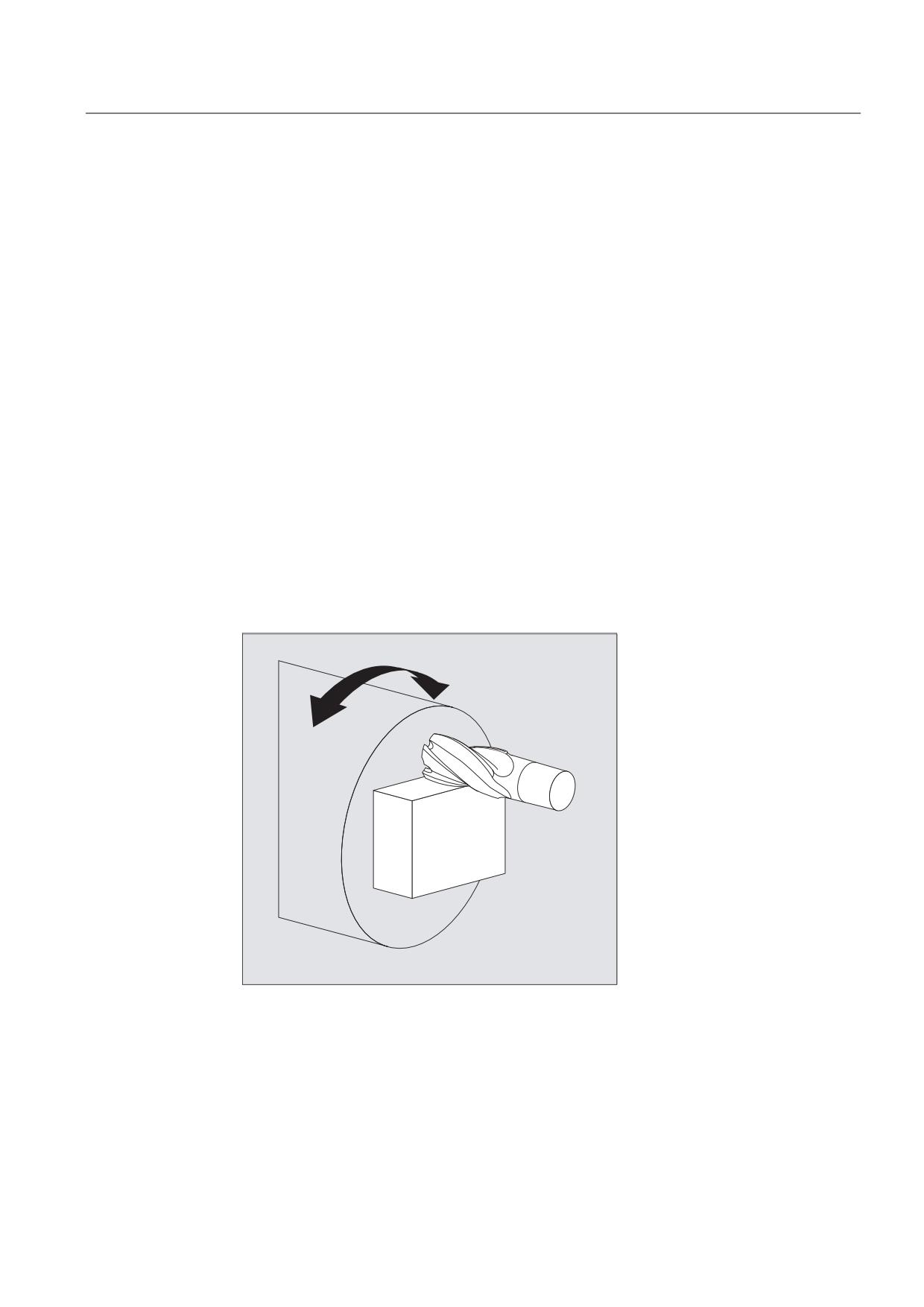
Milling on turned parts (TRANSMIT)
Function
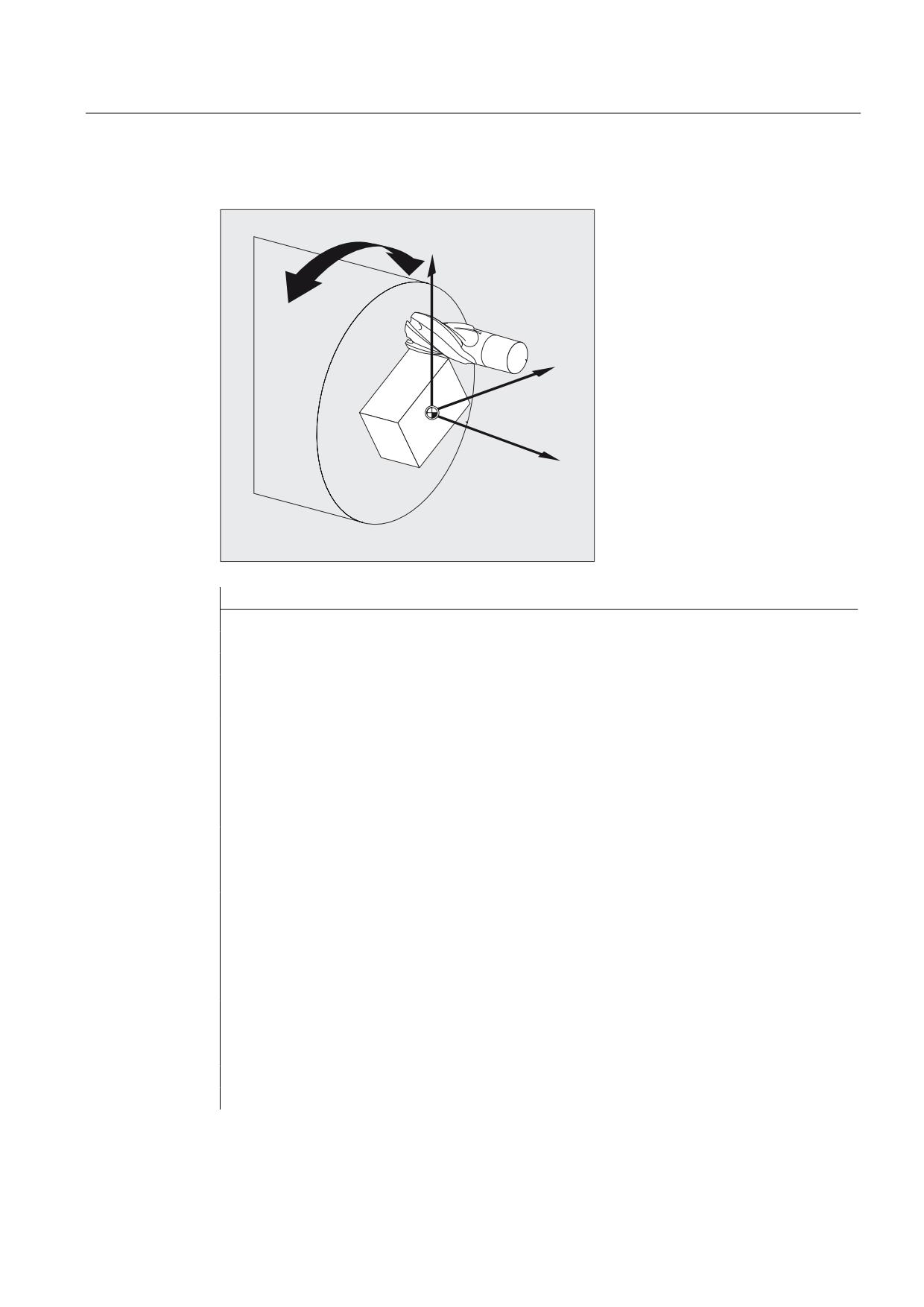
The TRANSMIT function enables the following:
● Face machining on turned parts in the turning clamp (drill-holes, contours).
● A cartesian coordinate system can be used to program these machining operations.
● The control maps the programmed traversing movements of the Cartesian coordinate
system onto the traversing movements of the real machine axes (standard situation):
- Rotary axis
- Infeed axis perpendicular to rotary axis
- Longitudinal axis parallel to rotary axis
- The linear axes are positioned perpendicular to one another.
● A tool center offset relative to the turning center is permitted.
● The velocity control makes allowance for the limits defined for the rotations.
Job Planning
Programming Manual, 03/2010, 6FC5398-2BP20-1BA0
359
Transformations
6.8 Kinematic transformation
TRANSMIT transformation types
The TRANSMIT machining operations have two parameterizable forms:
● TRANSMIT in the standard case with (TRAFO_TYPE_n = 256)
● TRANSMIT with additional Y linear axis (TRAFO_TYPE_n = 257)
The extended transformation type 257 can be used, for example, to compensate clamping
compensations of a tool with real Y axis.
Syntax
TRANSMIT or TRANSMIT(n)
TRAFOOF
Rotary axis
The rotary axis cannot be programmed because it is occupied by a geometry axis and
cannot thus be programmed directly as a channel axis.
Significance
TRANSMIT:
Activates the first declared TRANSMIT function. This function is also
designated as polar transformation.
TRANSMIT(n):
Activates the nth declared TRANSMIT function; n can be up to 2
(TRANSMIT(1) is the same as TRANSMIT).
TRAFOOF:
Deactivates an active transformation.
OFFN:
Offset contour normal: Distance of the face machining from the
programmed reference contour.
Note
An active TRANSMIT transformation is likewise deactivated if one of the other transformations
is activated in the relevant channel (e.g., TRACYL, TRAANG, TRAORI).
Job Planning
360
Programming Manual, 03/2010, 6FC5398-2BP20-1BA0
Transformations
6.8 Kinematic transformation
Example
<
;
=
Program code
Comments
N10 T1 D1 G54 G17 G90 F5000 G94
; Tool selection
N20 G0 X20 Z10 SPOS=45
; Approach the starting position
N30 TRANSMIT
; Activate TRANSMIT function
N40 ROT RPL=-45
; Set frame
N50 ATRANS X-2 Y10
N60 G1 X10 Y-10 G41 OFFN=1OFFN
; Square roughing; 1 mm tolerance
N70 X-10
N80 Y10
N90 X10
N100 Y-10
N110 G0 Z20 G40 OFFN=0
; Tool change
N120 T2 D1 X15 Y-15
N130 Z10 G41
N140 G1 X10 Y-10
; Square finishing
N150 X-10
N160 Y10
N170 X10
N180 Y-10
N190 Z20 G40
; Deselect frame
N200 TRANS
N210 TRAFOOF
N220 G0 X20 Z10 SPOS=45
; Approach the starting position
N230 M30
Job Planning
Programming Manual, 03/2010, 6FC5398-2BP20-1BA0
361
Transformations
6.8 Kinematic transformation
Description
Pole
There are two ways of passing through the pole:
● Traversal along linear axis
● Traverse to the pole, rotate the rotary axis at the pole and traveling away from the pole
Make the selection using MD 24911 and 24951.
TRANSMIT with additional Y linear axis (transformation type 257):
This transformation variant of the polar transformation makes use of the redundancy for a
machine with another linear axis in order to perform an improved tool compensation. The
following conditions then apply to the second linear axis:
● A smaller working area and
● The second linear axis should not be used for the retraction of the parts program.
Certain machine data settings are assumed for the parts program and the assignment of the
corresponding axes in the BCS or MCS, see
References
/FB2/ Function Manual Extended Functions; Kinematic Transformations (M1)
6.8.2
Cylinder surface transformation (TRACYL)
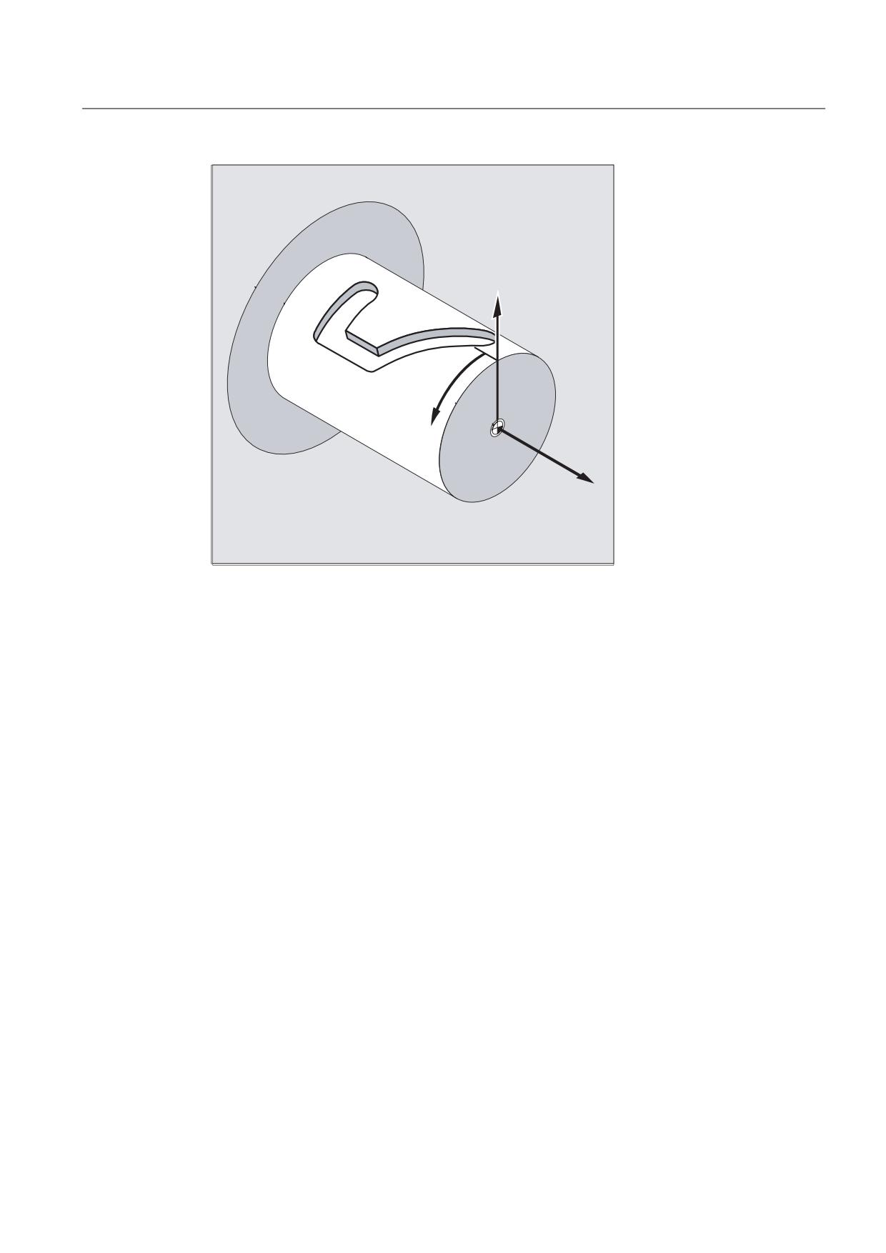
Function
The TRACYL cylinder surface transformation function can be used to:
Machine
● longitudinal grooves on cylindrical bodies,
● Transverse grooves on cylindrical objects,
● grooves with any path on cylindrical bodies.
The path of the grooves is programmed with reference to the unwrapped, level surface of the
cylinder.
Job Planning
362
Programming Manual, 03/2010, 6FC5398-2BP20-1BA0
Transformations
6.8 Kinematic transformation
;
<
=
TRACYL transformation types
There are three forms of cylinder surface coordinate transformation:
● TRACYL without groove wall offset (TRAFO_TYPE_n=512)
● TRACYL with groove wall offset: (TRAFO_TYPE_n=513)
● TRACYL with additional linear axis and groove wall offset: (TRAFO_TYPE_n=514)
The groove wall offset is parameterized with TRACYL using the third parameter.
For cylinder peripheral curve transformation with groove side compensation, the axis used
for compensation should be positioned at zero (y=0), so that the groove centric to the
programmed groove center line is finished.
Axis utilization
The following axes cannot be used as a positioning axis or a reciprocating axis:
● The geometry axis in the peripheral direction of the cylinder peripheral surface (Y axis)
● The additional linear axis for groove side compensation (Z axis).
Syntax
TRACYL(d) or TRACYL(d, n) or
for transformation type 514
TRACYL(d, n, groove side offset)
TRAFOOF
Rotary axis
The rotary axis cannot be programmed as it is occupied by a geometry axis and thus cannot
be programmed directly as channel axis.
Job Planning
Programming Manual, 03/2010, 6FC5398-2BP20-1BA0
363
Transformations
6.8 Kinematic transformation
Significance
TRACYL(d)
Activates the first TRACYL function specified in the channel
machine data. d is the parameter for the working diameter.
TRACYL (d, n)
Activates the n-th TRACYL function specified in the channel
machine data. The maximum for n is 2, TRACYL(d,1)
corresponds to TRACYL(d).
D
Value for the working diameter. The working diameter is
double the distance between the tool tip and the turning
center. This diameter must always be specified and be larger
than 1.
n
Optional 2nd parameter for the TRACYL data block 1
(preselected) or 2.
Slot side compensation Optional 3rd parameter whose value for TRACYL is
preselected using the mode for machine data.
Value range:
0: Transformation type 514 without groove wall offset as
previous
1: Transformation type 514 with groove wall offset
TRAFOOF
Transformation OFF (BCS and MCS are once again identical).
OFFN
Offset contour normal: Distance of the groove side from the
programmed reference contour.
Note
An active TRACYL transformation is likewise deactivated if one of the other transformations is
activated in the relevant channel (e.g., TRANSMIT, TRAANG, TRAORI).
Example: Tool definition
The following example is suitable for testing the parameterization of the TRACYL cylinder
transformation:
Program code
Comments
Tool parameters
Significance
Comment
Number (DP)
$TC_DP1[1,1]=120
Tool type
Milling tool
$TC_DP2[1,1]=0
Tool nose position
only for turning tools
Program code
Comments
Geometry
Length compensation
$TC_DP3[1,1]=8.
Length offset vector
Calculation acc. to type
$TC_DP4[1,1]=9.
and plane
$TC_DP5[1,1]=7.
Job Planning
364
Programming Manual, 03/2010, 6FC5398-2BP20-1BA0
Transformations
6.8 Kinematic transformation
Program code
Comments
Geometry
Radius
$TC_DP6[1,1]=6.
Radius
Tool radius
$TC_DP7[1,1]=0
Slot width b for slotting
saw, rounding radius for
milling tools
$TC_DP8[1,1]=0
Projection k
For slotting saw only
$TC_DP9[1,1]=0
$TC_DP10[1,1]=0
$TC_DP11[1,1]=0
Angle for taper milling
tools
Program code
Comments
Wear
Tool length and radius
compensation
$TC_DP12[1,1]=0
Remaining parameters to
Tool base dimension/adapter
$TC_DP24=0
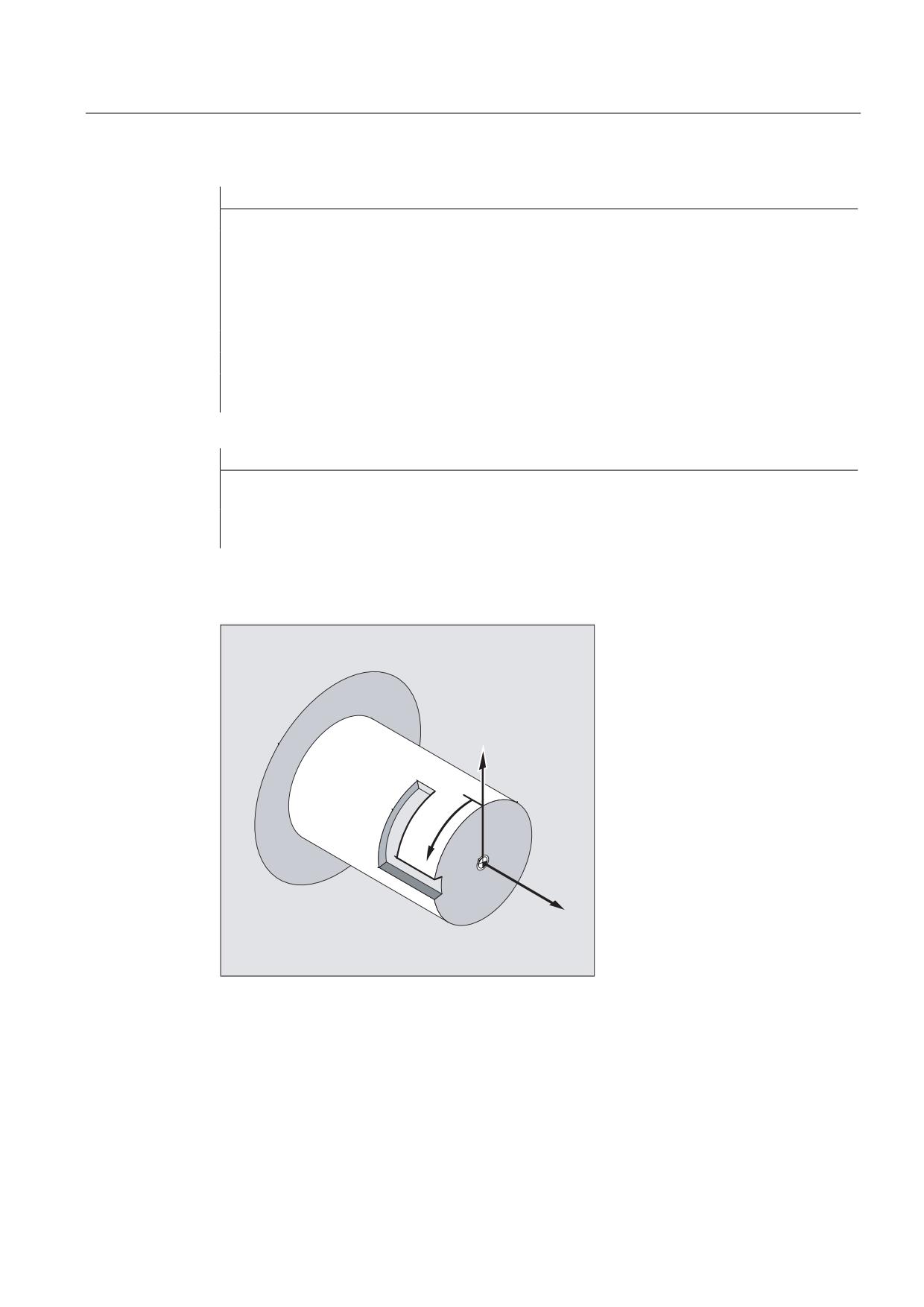
Example: Making a hook-shaped groove
;
<
=
Job Planning
Programming Manual, 03/2010, 6FC5398-2BP20-1BA0
365
Transformations
6.8 Kinematic transformation
Activate cylinder surface transformation:
Program code
Comments
N10 T1 D1 G54 G90 F5000 G94
; Tool selection, clamping compensation
N20 SPOS=0
; Approach the starting position
N30 G0 X25 Y0 Z105 CC=200
N40 TRACYL (40)
; Activate cylinder surface ;transformation
N50 G19
; Plane selection
Machining a hook-shaped groove:
Program code
Comments
N60 G1 X20
; Infeed tool to groove base
N70 OFFN=12
; Define 12 mm groove side spacing relative to
groove center line
N80 G1 Z100 G42
; Approach right side of groove
N90 G1 Z50
; Groove cut parallel to cylinder axis
N100 G1 Y10
; Groove cut parallel to circumference
N110 OFFN=4 G42
; Approach left side of the groove; define 4 mm
groove side spacing relative to the groove
center line
N120 G1 Y70
; Groove cut parallel to circumference
N130 G1 Z100
; Groove cut parallel to cylinder axis
N140 G1 Z105 G40
; Retract from groove wall
N150 G1 X25
; Retract
N160 TRAFOOF
N170 G0 X25 Y0 Z105 CC=200
; Approach the starting position
N180 M30
Job Planning
366
Programming Manual, 03/2010, 6FC5398-2BP20-1BA0
Transformations
6.8 Kinematic transformation
Description
Without groove wall offset (transformation type 512):
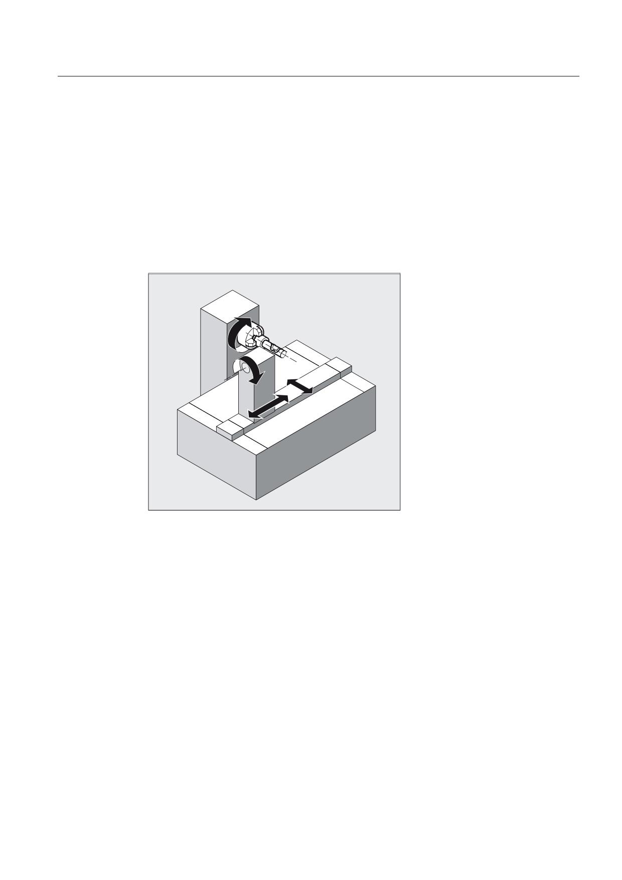
The control transforms the programmed traversing movements of the cylinder coordinate
system to the traversing movements of the real machine axes:
● Rotary axis
● Infeed axis perpendicular to rotary axis
● Longitudinal axis parallel to rotary axis
The linear axes are positioned perpendicular to one another. The infeed axis cuts the rotary
axis.
<
RU &0
$60
= RU =0
;0
With groove wall offset (transformation type 513):
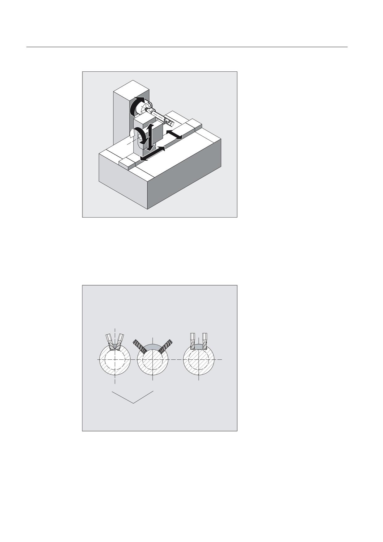
Kinematics as above, but an additional longitudinal axis parallel to the peripheral direction
The linear axes are positioned perpendicular to one another.
The velocity control makes allowance for the limits defined for the rotations.
Job Planning
Programming Manual, 03/2010, 6FC5398-2BP20-1BA0
367
Transformations
6.8 Kinematic transformation
<
RU &0
= RU =0
<0
$60
;0
Groove traversing-section
In the case of axis configuration 1, longitudinal grooves along the rotary axis are subject to
parallel limits only if the groove width corresponds exactly to the tool radius.
Grooves in parallel to the periphery (transverse grooves) are not parallel at the beginning
and end.
/RQJLWXGLQDO VORW 7UDQVYHUVH JURRYH
SDUDOOHO OLPLWHG ORQJLWXGL
QDO VORW ZLWK VORW ZDOO
ZLWKRXW JURRYH ZDOO RIIVHW FRPSHQVDWLRQ
75$)2B7<3(BQ
75$)2B7<3(BQ
Job Planning
368
Programming Manual, 03/2010, 6FC5398-2BP20-1BA0
Transformations
6.8 Kinematic transformation
With additional linear axis and groove wall offset (transformation type 514):
On a machine with a second linear axis, this transformation variant makes use of
redundancy in order to perform improved tool compensation. The following conditions then
apply to the second linear axis:
● a smaller working area and
● the second linear axis should not be used for the travel through the parts program.
Certain machine data settings are assumed for the parts program and the assignment of the
corresponding axes in the BCS or MCS, see
References
/FB2/ Function Manual Extended Functions; Kinematic Transformations (M1)
Offset contour normal OFFN (transformation type 513)
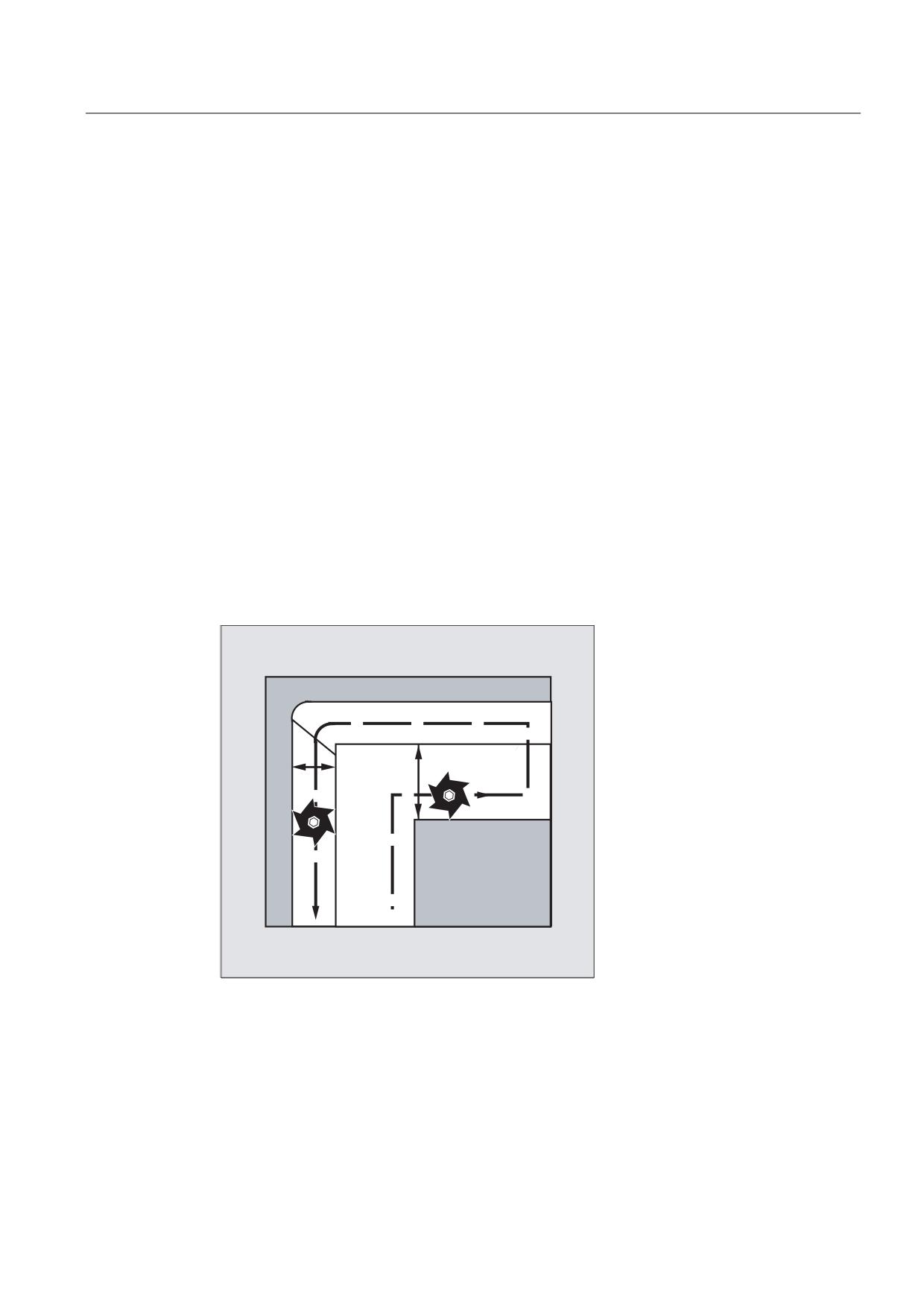
To mill grooves with TRACYL, the following is programmed:
● groove center line in the part program,
● half the groove width programmed using OFFN.
To avoid damage to the groove side OFFN acts only when the tool radius compensation is
active. Furthermore, OFFN should also be >= the tool radius to avoid damage occurring to
the opposite side of the groove.
SURJUDPPHG
2))1
FRQWRXU
Job Planning
Programming Manual, 03/2010, 6FC5398-2BP20-1BA0
369
Transformations
6.8 Kinematic transformation
A parts program for milling a groove generally comprises the following steps:
1. Selecting a tool
2. Select TRACYL
3. Select suitable coordinate offset (frame)
4. Position
5. Program OFFN
6. Select TRC
7. Approach block (position TRC and approach groove side)
8. Groove center line contour
9. Deselect TRC
10.Retraction block (retract TRC and move away from groove side)
11.Position
12.TRAFOOF
13.Re-select original coordinate shift (frame)
Special features
● TRC selection:
TRC is not programmed in relation to the groove side, but relative to the programmed
groove center line. To prevent the tool traveling to the left of the groove side, G42 is
entered (instead of G41). You avoid this if in OFFN, the groove width is entered with a
negative sign.
● OFFN acts differently with TRACYL than it does without TRACYL. As, even without TRACYL, OFFN
is included when TRC is active, OFFN should be reset to zero after TRAFOOF.
● It is possible to change OFFN within a parts program. This could be used to shift the
groove center line from the center (see diagram).
● Guiding grooves:
TRACYL does not create the same groove for guiding grooves as it would be with a tool
with the diameter producing the width of the groove. It is basically not possible to create
the same groove side geometry with a smaller cylindrical tool as it is with a larger one.
TRACYL minimizes the error. To avoid problems of accuracy, the tool radius should only be
slightly smaller than half the groove width.
Note
OFFN and TRC
With TRAFO_TYPE_n = 512, the value is effective under OFFN as an allowance for TRC.
With TRAFO_TYPE_n = 513, half the groove width is programmed in OFFN. The contour is
retracted with OFFN-TRC.
Job Planning
370
Programming Manual, 03/2010, 6FC5398-2BP20-1BA0
Transformations
6.8 Kinematic transformation
6.8.3
Inclined axis (TRAANG)
Function
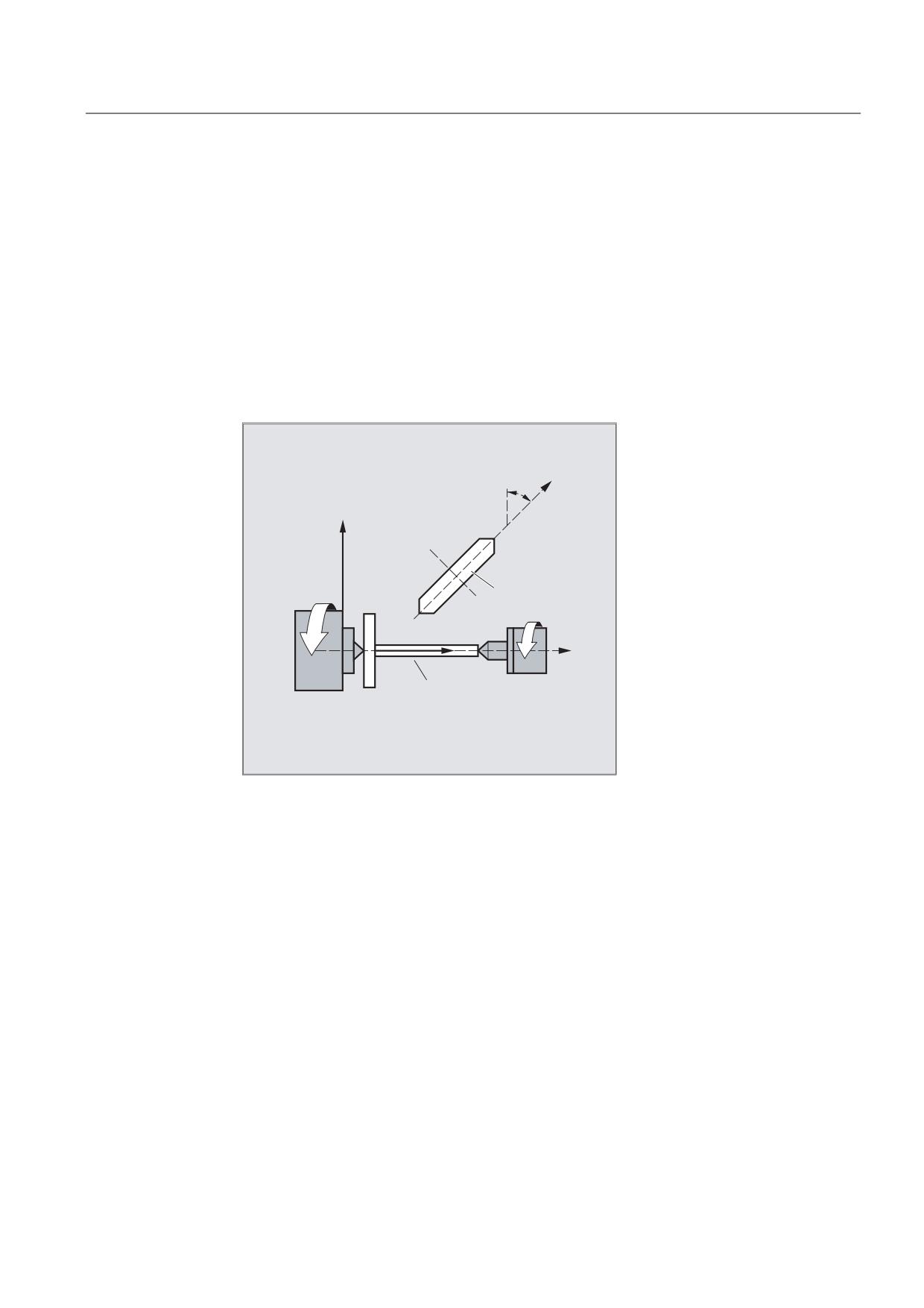
The inclined axis function is intended for grinding technology and facilitates the following
performance:
● Machining with an oblique infeed axis
● A Cartesian coordinate system can be used for programming purposes.
● The control maps the programmed traversing movements of the Cartesian coordinate
system onto the traversing movements of the real machine axes (standard situation):
Inclined infeed axis.
08
༾
;
*ULQGLQJ GLVF
&
=
$6
0=
:RUNSLHFH
Syntax
TRAANG(α) or TRAANG(α, n)
TRAFOOF
Significance
TRAANG( ) or
Activate transformation with the parameterization of the previous
TRAANG( ,n)
selection.
TRAANG(α)
Activates the first specified inclined axis transformation
TRAANG(α,n)
Activates the nth agreed inclined axis transformation. The maximum
value of n is 2. TRAANG(α,1) corresponds to TRAANG(α).
Job Planning
Programming Manual, 03/2010, 6FC5398-2BP20-1BA0
371
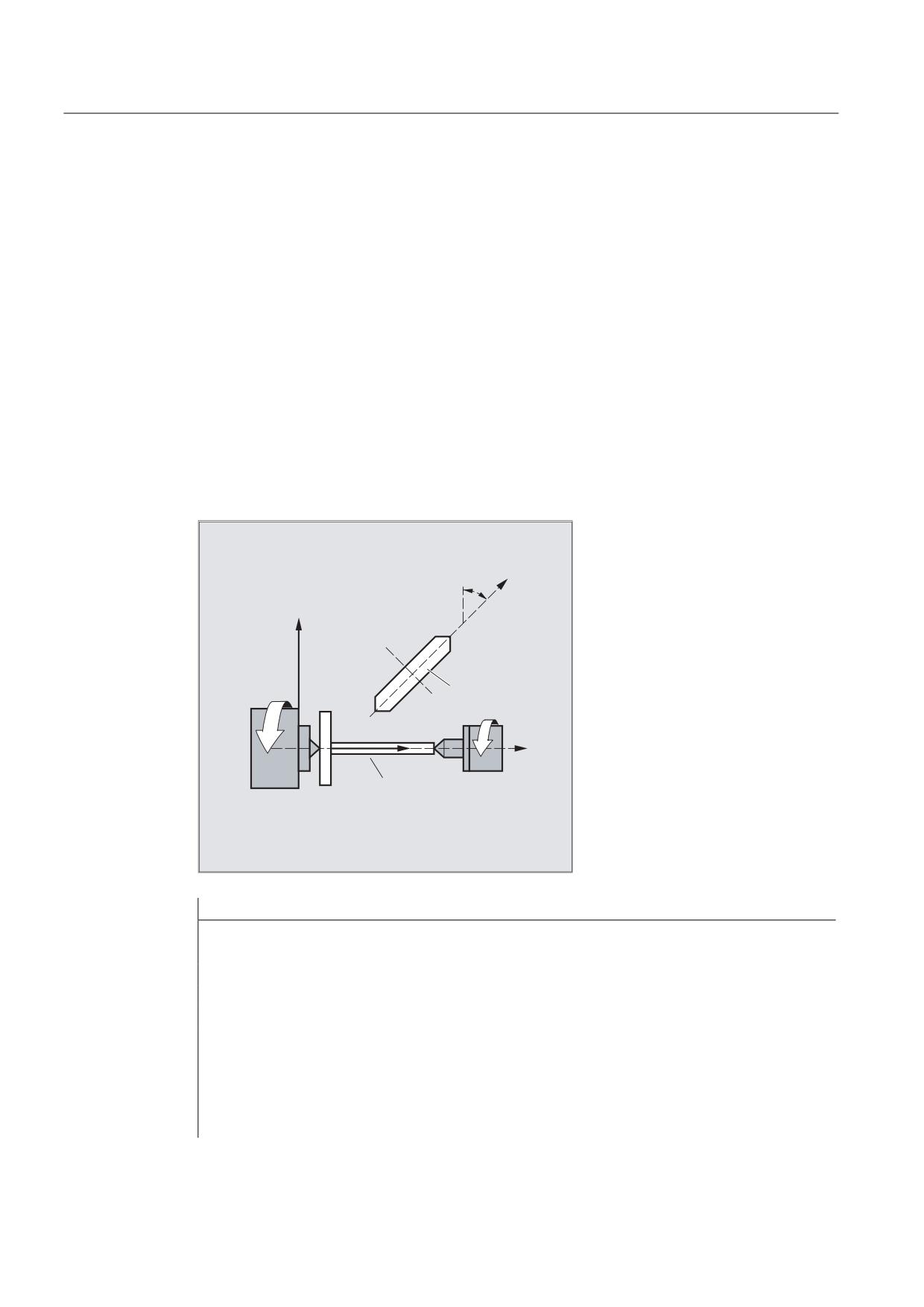
Transformations
6.8 Kinematic transformation
αA
Angle of the inclined axis
Permissible values for α are:
-90 degrees < α < + 90 degrees
TRAFOOF
Transformation off
n
Number of agreed transformations
Angle α omitted or zero
If α (angle) is omitted (e.g., TRAANG(), TRAANG(, n) ), the transformation is activated with the
parameterization of the previous selection. On the first selection, the default settings
according to the machine data apply.
An angle α = 0 (e.g., TRAANG(0), TRAANG(0,n)) is a valid parameter setting and is no longer
equivalent to the omission of the parameter, as in the case of older versions.
Example
08
༾
;
*ULQGLQJ GLVF
&
=
$6
0=
:RUNSLHFH
Program code
Comments
N10 G0 G90 Z0 MU=10 G54 F5000 ->
; Tool selection, clamping compensation,
-> G18 G64 T1 D1
Plane selection
N20 TRAANG(45)
; Activate inclined axis transformation
N30 G0 Z10 X5
; Approach the starting position
N40 WAITP(Z)
; Release axis for oscillation
N50 OSP[Z]=10 OSP2[Z]=5 OST1[Z]=-2 ->
; Oscillation until the dimension is reached
-> OST2[Z]=-2 FA[Z]=5000
(Oscillation, see Chapter "Oscillation")
N60 OS[Z]=1
N70 POS[X]=4.5 FA[X]=50
N80 OS[Z]=0
Job Planning
372
Programming Manual, 03/2010, 6FC5398-2BP20-1BA0
Transformations
6.8 Kinematic transformation
Program code
Comments
N90 WAITP(Z)
; Release oscillating axes as positioning
axes
N100 TRAFOOF
; Deactivate transformation
N110 G0 Z10 MU=10
; Retract
N120 M30
;
-> program in a single block
Description
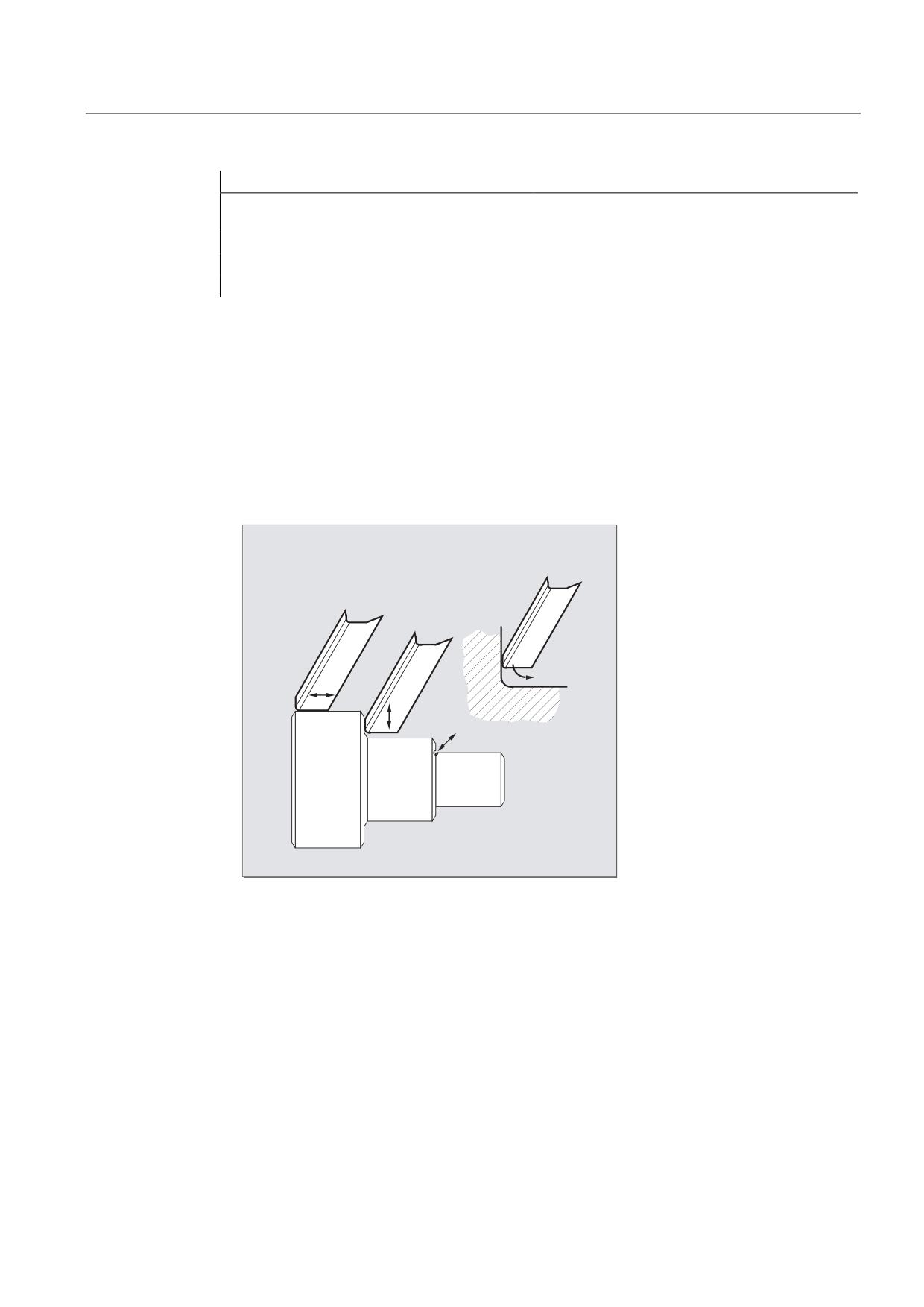
The following machining operations are possible:
1. Longitudinal grinding
2. Face grinding
3. Grinding of a specific contour
4. Oblique plunge-cut grinding.
Machine manufacturer
The following settings are defined in machine data:
● The angle between a machine axis and the oblique axis,
● The position of the zero point of the tool relative to the origin of the coordinate system
specified by the "inclined axis" function,
● The speed reserve held ready on the parallel axis for the compensating movement,
● The axis acceleration reserve held ready on the parallel axis for the compensating
movement.
Job Planning
Programming Manual, 03/2010, 6FC5398-2BP20-1BA0
373
Transformations
6.8 Kinematic transformation
Axis configuration
To program in the Cartesian coordinate system, it is necessary to inform the control of the
correlation between this coordinate system and the actually existing machine axes (MU,MZ):
● Assignment of names to geometry axes
● Assignment of geometry axes to channel axes
- general situation (inclined axis not active)
- inclined axis active
● Assignment of channel axes to machine axis numbers
● Identification of spindles
● Allocation of machine axis names.
Apart from "inclined axis active", the procedure corresponds to the procedure for normal axis
configuration.
6.8.4
Inclined axis programming (G05, G07)
Function
In Jog mode, the movement of the grinding wheel can either be cartesian or in the direction
of the inclined axis (the display stays cartesian). All that moves is the real U axis, the Z axis
display is updated.
In jog-mode, REPOS-offsets must be traversed using Cartesian coordinates.
In jog-mode with active
"PTP-travel", the Cartesian operating range limit is monitored for overtravel and the relevant
axis is braked beforehand. If "PTP travel" is not active, the axis can be traversed right up to
the operating range limit.
References
/FB2/ Description of Functions Extended Functions; Kinematic Transformation (M1)
Syntax
G07
G05
The commands G07/G05 are used to make it easier to program the inclined axes. Positions
can be programmed and displayed in the Cartesian coordinate system. Tool compensation
and zero offset are included in Cartesian coordinates. After the angle for the inclined axis is
programmed in the NC program, the starting position can be approached (G07) and then the
oblique plunge-cutting (G05) performed.
Job Planning
374
Programming Manual, 03/2010, 6FC5398-2BP20-1BA0
Transformations
6.8 Kinematic transformation
Significance
G07
Approach starting position
G05
Activates oblique plunge-cutting
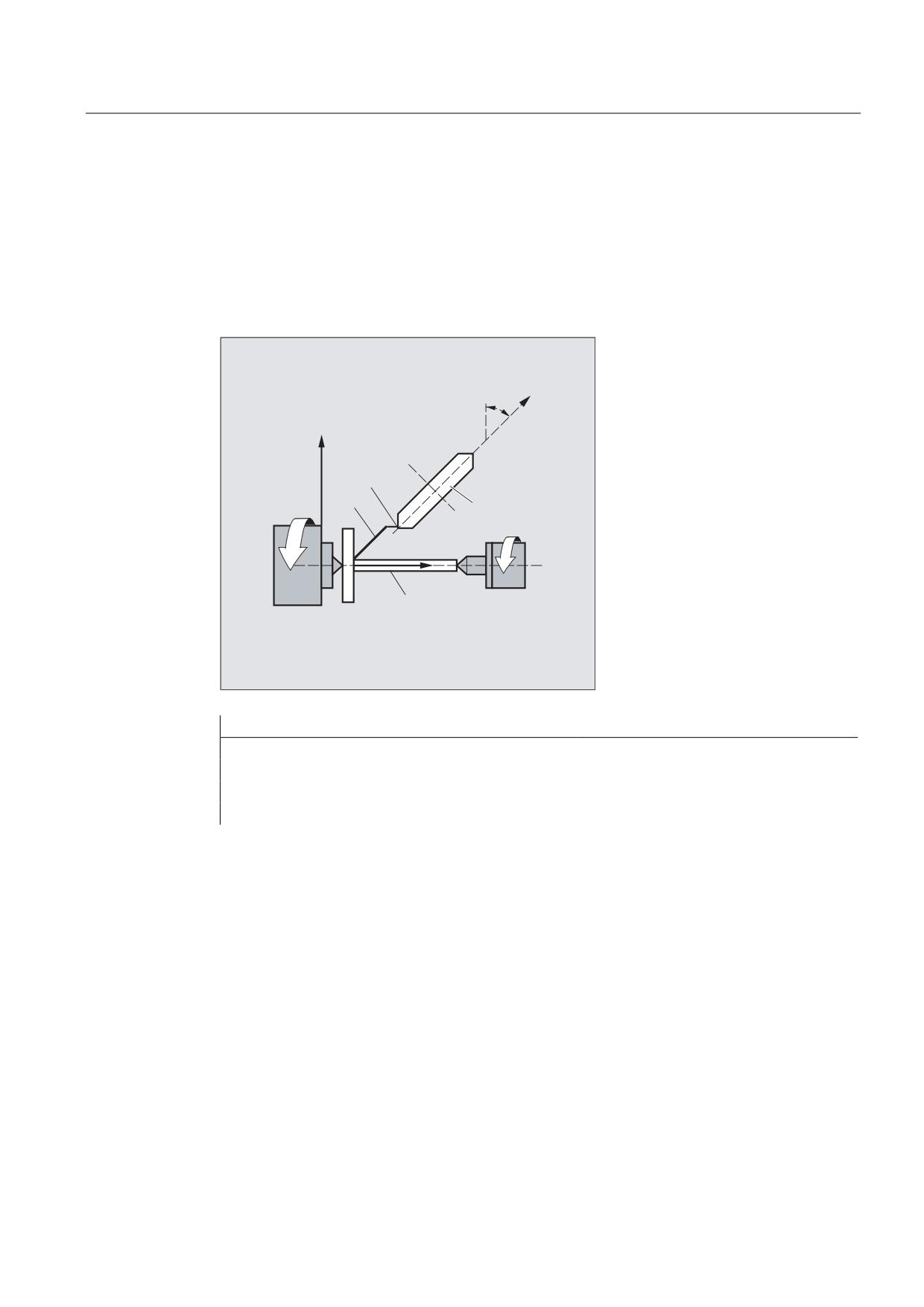
Example
9
˞
;
1
1
*ULQGLQJ GLVF
&
=
$6
:RUNSLHFH
Programming
Comments
N.. G18
; Program angle for inclined axis
N50 G07 X70 Z40 F4000
; Approach starting position
N60 G05 X70 F100
; Oblique plunge-cutting
N70 ...
;
Job Planning
Programming Manual, 03/2010, 6FC5398-2BP20-1BA0
375
Transformations
6.9 Cartesian PTP travel
6.9
Cartesian PTP travel
Function
This function can be used to program a position in a cartesian coordinate system, however,
the movement of the machine occurs in the machine coordinates. The function can be used,
for example, when changing the position of the articulated joint, if the movement runs
through a singularity.
Note
The function can only be used meaningfully in conjunction with an active transformation.
Furthermore, "PTP travel" is only permissible in conjunction with G0 and G1.
Syntax
N... TRAORI
N... STAT='B10' TU='B100' PTP
N... CP
PTP transversal with generic 5/6-axis transformation
If point-to-point transversal is activated in the machine coordinate system (ORIMKS) during an
active generic 5/6-axis transformation with PTP, tool orientation can be programmed both
with rotary axis positions
N... G1 X Y Z A B C
as well as with Euler and/or RPY angle vectors irrespective of the kinematics
N... ORIEULER or ORIRPY
N... G1 X Y Z A2 B2 C2
or the direction vectors
N... G1 X Y Z A3 B3 C3
Both rotary axis interpolation, vector interpolation with large circle interpolation ORIVECT or
interpolation of the orientation vector on a peripheral surface of a taper ORICONxx may be
active.
Non-uniqueness of orientation with vectors
When programming the orientation with vectors, there is non-uniqueness in the rotary axis
positions available. The rotary axis positions to be approached can be selected by
programming STAT = <...>. If
If STAT = 0 is programmed (this is equivalent to the default setting),
the positions which are at the shortest distance from the start positions are approached. If
STAT = 1 is programmed,
the positions which are at a greater distance from the start positions are approached.
Job Planning
376
Programming Manual, 03/2010, 6FC5398-2BP20-1BA0
Transformations
6.9 Cartesian PTP travel
Significance
The PTP and CP commands act in a modal manner. CP is the default setting.
If modal applies when programming the STAT value, TU programming is = <...> non-modal.
Another difference is that programming a STAT value only has an effect during vector
interpolation, while programming TU is also evaluated during active rotary axis interpolation.
PTP
point to point (point to point motion)
The movement is executed as a synchronized axis movement; the slowest axis
involved in the movement is the dominating axis for the velocity.
CP
continuous path (path motion)
The movement is executed as Cartesian path motion.
STAT= Position of the articulated joints; this value is dependent on the transformation.
TU=
TURN information acts blockwise. This makes it possible to clearly approach axis
angles between -360 degrees and +360 degrees.
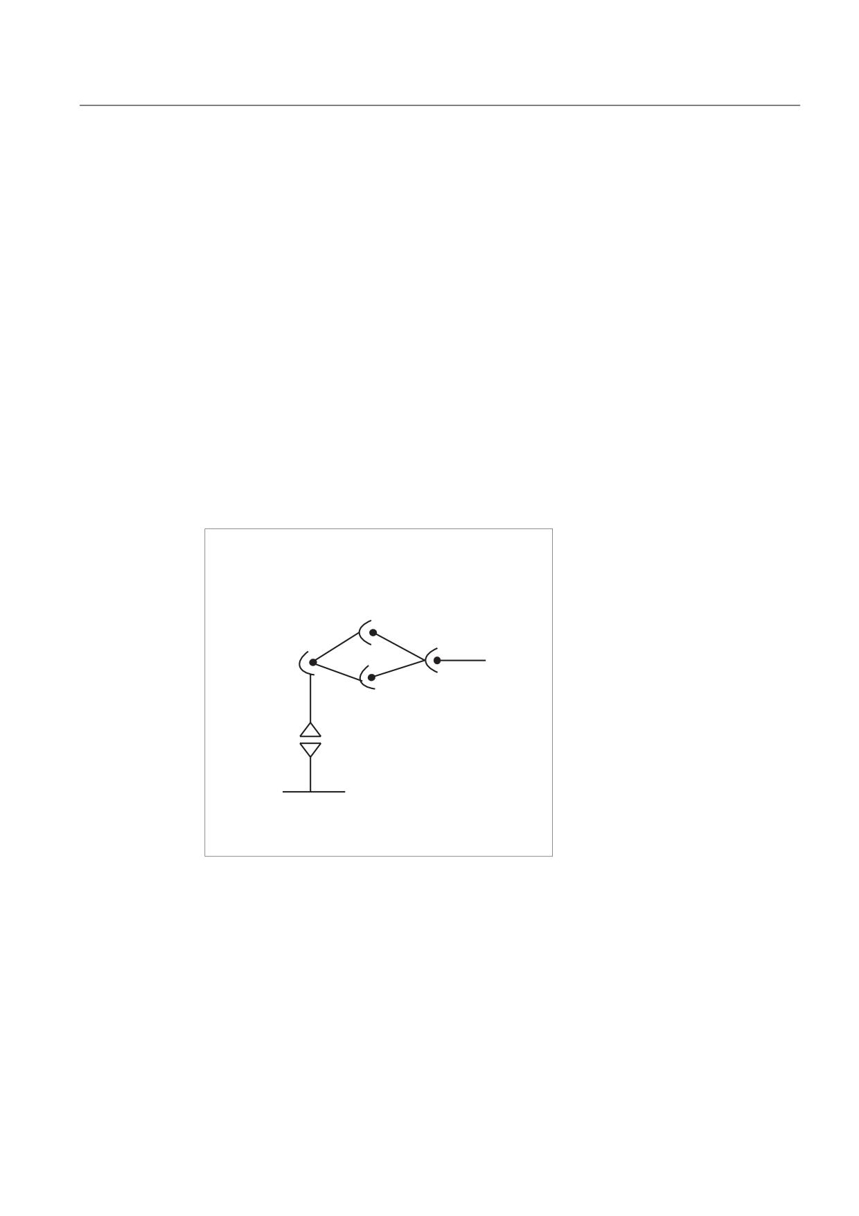
Example
(OERZ XS
$
=
<
(OERZ GRZQ
;
N10 G0 X0 Y-30 Z60 A-30 F10000
Initial setting
→ Elbow up
N20 TRAORI(1)
Transformation on
N30 X1000 Y0 Z400 A0
N40 X1000 Z500 A0 STAT='B10'
Re-orientation without transformation
TU='B100' PTP
→ Elbow down
Job Planning
Programming Manual, 03/2010, 6FC5398-2BP20-1BA0
377
Transformations
6.9 Cartesian PTP travel
N50 X1200 Z400 CP
Transformation active again
N60 X1000 Z500 A20
N70 M30
PTP transversal with generic 5-axis transformation
Assumption: This is based on a right-angled CA kinematics.
Program code
Comments
TRAORI
; Transformation CA kinematics on
PTP
; Activate PTP traversing
N10 A3 = 0 B3 = 0 C3 = 1
; Rotary axis positions C = 0 A = 0
N20 A3 = 1 B3 = 0 C3 = 1
; Rotary axis positions C = 90 A = 45
N30 A3 = 1 B3 = 0 C3 = 0
; Rotary axis positions C = 90 A = 90
N40 A3 = 1 B3 = 0 C3 = 1 STAT =
; Rotary axis positions C = 270 A = -45
1
Select clear approach position of rotary axis position:
In block N40, by programming STAT = 1, the rotary axes then travel the long route from their
starting point (C=90, A=90) to the end point (C=270, A=-45), rather than the case would be if
STAT = 0 where they would travel the shortest route to the end point (C=90, A=45).
Description
The commands PTP and CP effect the changeover between Cartesian traversal and traversing
the machine axes.
PTP transversal with generic 5/6-axis transformation
During PTP transversal, unlike 5/6-axis transformation, the TCP generally does not remain
stationary if only the orientation changes. The transformed end positions of all transformation
axes (3 linear axes and up to 3 round axes) are approached in linear fashion without the
transformation still actually being active.
The PTP transversal is deactivated by programming the modal G code CP.
The various transformations are included in the document:
/FB3/ Function Manual Special Functions; Handling Transformation Package (TE4).
Programming the position (STAT=)
A machine position is not uniquely determined just by positional data with Cartesian
coordinates and the orientation of the tool. Depending on the kinematics involved, there can
be as many as eight different and crucial articulated joint positions. These are specific to the
transformation. To be able to uniquely convert a Cartesian position into the axis angle, the
position of the articulated joints must be specified with the command STAT=. The "STAT"
command contains a bit for each of the possible positions as a binary value.
For information about the setting bits to be programmed for "STAT", see:
/FB2/ Description of Functions Extended Functions; Kinematic Transformation (M1),
"Cartesian PTP travel" section.
Job Planning
378
Programming Manual, 03/2010, 6FC5398-2BP20-1BA0

Transformations
6.9 Cartesian PTP travel
Programming the axis angle (TU=)
To be able to clearly approach axis angles < ± 360 degrees, this information must be
programmed using the command "TU=".
The axes traverse by the shortest path:
● when no TU is programmed for a position,
● with axes that have a traversing range > ±360 degrees.
Example:
The target position shown in the diagram can be approached in the negative or positive
direction. The direction is programmed under address A1.
A1=225°, TU=Bit 0, → positive direction
A1=-135°, TU=Bit 1, → negative direction
6WDUWLQJ SRVLWLRQ
1HJDWLYH
3RVLWLYH
GLUHFWLRQ
GLUHFWLRQ
7DUJHW SRVLWLRQ
Example of evaluation of TU for generic 5/6-axis transformation and target positions
Variable TU contains a bit, which indicates the traversing direction for every axis involved in
the transformation. The assignment of TU bits matches the channel axis view of the round
axes. The TU information is only evaluated for the up to 3 possible round axes which are
included in the transformation:
Bit0: Axis 1, TU bit = 0 : 0 degrees <= round axis angle < 360 degrees
Bit1: Axis 2, TU bit = 1 : -360 degrees < round axis angle < 0 degrees
The start position of a round axis is C = 0. By programming C = 270, the round axis travels to
the following target positions:
C = 270: TU bit 0, positive direction of rotation
C = -90: TU bit 1, negative direction of rotation
Job Planning
Programming Manual, 03/2010, 6FC5398-2BP20-1BA0
379
Transformations
6.9 Cartesian PTP travel
Further behavior
Mode change
The "Cartesian PTP travel" function is only useful in the AUTO and MDA modes of
operation. When changing the mode to JOG, the current setting is retained.
When the G code PTP is set, the axes will traverse in MCS. When the G code CP is set, the
axes will traverse in WCS.
Power On/RESET
After a power ON or after a RESET, the setting is dependent on the machine data
$MC_GCODE_REST_VALUES[48]. The default traversal mode setting is "CP".
REPOS
If the function "Cartesian PTP travel" was set during the interruption block, PTP can also be
used for repositioning.
Overlaid movements
DRF offset or external zero offset are only possible to a limited extent in Cartesian PTP
travel. When changing from PTP to CP movement, there must be no overrides in the BCS.
Smoothing between CP and PTP motion
A programmable transition rounding between the blocks is possible with G641.
The size of the rounding area is the path in mm or inch, from which or to which the block
transition is to be rounded. The size must be specified as follows:
● for G0 blocks with ADISPOS
● for all the other motion commands with ADIS.
The path calculation corresponds to considering of the F addresses for non-G0 blocks. The
feed is kept to the axes specified in FGROUP(..).
Feed calculation
For CP blocks, the Cartesian axes of the basic coordinate system are used for the
calculation.
For PTP blocks, the corresponding axes of the machine coordinate system are used for the
calculation.
Job Planning
380
Programming Manual, 03/2010, 6FC5398-2BP20-1BA0
Transformations
6.9 Cartesian PTP travel
6.9.1
PTP for TRANSMIT
Function
PTP for TRANSMIT can be used to approach G0 and G1 blocks time-optimized. Rather than
traversing the axes of the Basic Coordinate System linearly (CP), the machine axes are
traversed linearly (PTP). The effect is that the machine axis motion near the pole causes the
block end point to be reached much faster.
The part program is still written in the Cartesian workpiece coordinate system and all
coordinate offsets, rotations and frame programming settings remain valid. The simulation on
HMI, is also displayed in the Cartesian Workpiece coordinate system.
Syntax
N... TRANSMIT
N... PTPG0
N... G0
N... G1 ...
Significance
TRANSMIT Activates the first declared TRANSMIT function
(see section "Milling on turned parts: TRANSMIT")
PTPG0
Point to Point G0 (point-to-point motion automatic at each G0 block and then
set CP again)
Because STAT and TU are modal, the most recently programmed value
always acts.
PTP
point to point; (point to point motion)
For TRANSMIT, PTP means that in the Cartesian spirals will be retracted to
Archimedean spirals either about the pole or from the pole. The resulting tool
motions run significantly different as for CP and are represented in the
associated programming examples.
STAT=
Resolving the non-uniqueness with regard to the pole.
TU=
TU is not relevant for PTP with TRANSMIT
Job Planning
Programming Manual, 03/2010, 6FC5398-2BP20-1BA0
381
Transformations
6.9 Cartesian PTP travel
Example of circumnavigation of the pole with PTP and TRANSMIT
<
373
&3
1
* ;
<
1
;
<
;
Program code
Comments
N001 G0 X30 Z0 F10000 T1 D1 G90
; Initial setting, absolute
dimension
N002 SPOS=0
N003 TRANSMIT
; Transformation TRANSMIT
N010 PTPG0
; For each G0 block, automatically
PTP followed by CP
N020 G0 X30 Y20
N030 X-30 Y-20
N120 G1 X30 Y20
N110 X30 Y0
M30
Job Planning
382
Programming Manual, 03/2010, 6FC5398-2BP20-1BA0
Transformations
6.9 Cartesian PTP travel
Example of the retraction from the pole with PTP and TRANSMIT
PTP
30
CP
N070 X20 Y2
20
10
N060 X0 Y0
-30
-20
-10
10
20
30
-10
-20
-30
N050 X10 Y0
Programming
Comments
N001 G0 X90 Z0 F10000 T1 D1 G90
; Initial setting
N002 SPOS=0
N003 TRANSMIT
; Transformation TRANSMIT
N010 PTPG0
; For each G0 block, automatically
PTP followed by CP
N020 G0 X90 Y60
N030 X-90 Y-60
N040 X-30 Y-20
N050 X10 Y0
N060 X0 Y0
N070 X-20 Y2
N170 G1 X0 Y0
N160 X10 Y0
N150 X-30 Y-20
M30
Job Planning
Programming Manual, 03/2010, 6FC5398-2BP20-1BA0
383
Transformations
6.9 Cartesian PTP travel
Description
PTP and PTPG0
PTPG0 is considered for all transformations that can process PTP. PTPG0 is not relevant is all
other cases.
G0 blocks are processed in CP mode.
The selection of PTP or PTPG0 is performed in the parts program or by the deselection of CP
in the machine data $MC_GCODE_RESET_VALUES[48].
CAUTION
Restrictions
With regard to tool motions and collision, a number of restrictions and certain function
exclusions apply, such as:
no tool radius compensation (TRC) may be active with PTP.
With PTPG0 , for active tool radius compensation (TRC), is traversed by CP.
PTP does not permit smooth approach and retraction (SAR).
With PTPG0, CP traversal is used for smooth approach and retraction (SAR).
PTP does not permit cutting cycles (CONTPRON, CONTDCON).
With PTPG0 cutting cycles (CONTPRON, CONTDCON) are traversed by CP.
Chamfer (CHF, CHR) and rounding (RND, RNDM) are ignored.
Compressor is not compatible with PTP and will automatically be deselected in PTP
blocks.
An axis superimposing in the interpolation may not change during the PTP section.
If G643 is specified, an automatic switch to G642 is made after smoothing with axial
accuracy.
For active PTP, the transformation axes cannot be simultaneously positioning axes.
References:
/FB2/ Function Manual Extended Functions; Kinematic Transformation (M1),
"Cartesian PTP travel" section
PTP for TRACON:
PTP can also be used with TRACON, provided the first chained transformation supports PTP.
Meaning of STAT= and TU= for TRANSMIT
If a rotary axis is to turn by 180 degrees or the contour for CP passes through the pole,
rotary axes depending on the machine data $MC_TRANSMIT_POLE_SIDE_FIX_1/2 [48] can be
turned by -/+ 180 degrees and traversed in clockwise or counter-clockwise direction. It can
also be set whether traversal is to go through the pole or whether rotation around the pole is
to be performed.
Job Planning
384
Programming Manual, 03/2010, 6FC5398-2BP20-1BA0
Transformations
6.10 Constraints when selecting a transformation
6.10
Constraints when selecting a transformation
Function
Transformations can be selected via a parts program or MDA. Please note:
● No intermediate movement block is inserted (chamfer/radii).
● Spline block sequences must be excluded; if not, a message is displayed.
● Fine tool compensation must be deselected (FTOCOF); if not a message is displayed.
● Tool radius compensation must be deselected (G40); if not a message is displayed.
● An activated tool length offset is included in the transformation by the control.
● The control deselects the current frame active before the transformation.
● The control deselects an active operating range limit for axes affected by the
transformation (corresponds to WALIMOF).
● Protection zone monitoring is deselected.
● Continuous path control and rounding are interrupted.
● All the axes specified in the machine data must be synchronized relative to a block.
● Axes that are exchanged are exchanged back; if not, a message is displayed.
● A message is output for dependent axes.
Tool change
Tools may only be changed when the tool radius compensation function is deselected.
A change in tool length offset and tool radius compensation selection/deselection must not
be programmed in the same block.
Frame change
All statements, which refer exclusively to the base coordinate system, are permissible
(FRAME, tool radius compensation). However, a frame change with G91 (incremental
dimension) - unlike with an inactive transformation - is not handled separately. The
increment to be traveled is evaluated in the workpiece coordinate system of the new frame -
regardless of which frame was effective in the previous block.
Exceptions
Axes affected by the transformation cannot be used
● as a preset axis (alarm),
● for approaching a checkpoint (alarm),
● for referencing (alarm).
Job Planning
Programming Manual, 03/2010, 6FC5398-2BP20-1BA0
385
Transformations
6.11 Deselect transformation (TRAFOOF)
6.11
Deselect transformation (TRAFOOF)
Function
The TRAFOOF command deactivates all active transformations and frames.
Note
Frames required after this must be activated by renewed programming.
Please note:
The same restrictions as for selection are applicable to deselecting the transformation (see
section "Constraints when selecting a transformation").
Syntax
TRAFOOF
Significance
TRAFOOF
Command for deactivating all active transformations/frames
Job Planning
386
Programming Manual, 03/2010, 6FC5398-2BP20-1BA0
Transformations
6.12 Chained transformations (TRACON, TRAFOOF)
6.12
Chained transformations (TRACON, TRAFOOF)
Function
Two transformations can be chained so that the motion components for the axes from the
first transformation are used as input data for the chained second transformation. The motion
parts from the second transformation act on the machine axes.
The chain may include two transformations.
Note
A tool is always assigned to the first transformation in a chain. The subsequent
transformation then behaves as if the active tool length were zero. Only the basic tool
lengths set in the machine data (_BASE_TOOL_) are valid for the first transformation in the
chain.
Machine manufacturer
Take note of information provided by the machine manufacturer on any transformations
predefined by the machine data.
Transformations and chained transformations are options. The current catalog always
provides information about the availability of specific transformations in the chain in specific
controls.
Applications
● Grinding contours that are programmed as a side line of a cylinder (TRACYL) using an
inclined grinding wheel, e.g., tool grinding.
● Finish cutting of a contour that is not round and was generated with TRANSMIT using
inclined grinding wheel.
Syntax
TRACON(trf,par)
This activates a chained transformation.
TRAFOOF
Job Planning
Programming Manual, 03/2010, 6FC5398-2BP20-1BA0
387
Transformations
6.12 Chained transformations (TRACON, TRAFOOF)
Significance
TRACON
This activates the chained transformation. If another transformation was
previously activated, it is implicitly disabled by means of TRACON().
TRAFOOF
The most recently activated (chained) transformation will be disabled.
trf
Number of the chained transformation:
0 or 1 for first/single chained transformation.
If nothing is programmed here, then this has the same meaning as
specifying value 0 or 1, i.e., the first/single transformation is activated.
2 for the second chained transformation. (Values not equal to 0 - 2
generate an error alarm).
par
One or more parameters separated by a comma for the transformations in
the chain expecting parameters, for example, the angle of the inclined axis.
If parameters are not set, the defaults or the parameters last used take
effect. Commas must be used to ensure that the specified parameters are
evaluated in the sequence in which they are expected, if default settings
are to be effective for previous parameters. In particular, a comma is
required before at least one parameter, even though it is not necessary to
specify trf. For example: TRACON( , 3.7).
Requirements
The second transformation must be "Inclined axis" (TRAANG). The first transformation can be:
● Orientation transformations (TRAORI), including universal milling head
● TRANSMIT
● TRACYL
● TRAANG
It is a condition of using the activate command for a chained transformation that the
individual transformations to be chained and the chained transformation to be activated are
defined by the machine data.
The supplementary conditions and special cases indicated in the individual transformation
descriptions are also applicable for use in chained transformations.
Information on configuring the machine data of the transformations can be found in:
/FB2/ Function Manual Extended Functions; Kinematic Transformations (M1) and
/FB3/ Function Manual, Special Functions; 3- to 5-Axis Transformations (F2).
Job Planning
388
Programming Manual, 03/2010, 6FC5398-2BP20-1BA0
Tool offsets
7
7.1
Offset memory
Function
Structure of the offset memory
Every data field can be invoked with a T and D number (except "Flat D No."); in addition to
the geometrical data for the tool, it contains other information such as the tool type.
Flat D number structure
The "Flat D No. structure" is used if tool management takes place outside the NCK. In this
case, the D numbers are created with the corresponding tool compensation blocks without
assignment to tools.
T can continue to be programmed in the part program. However, this T has no reference to
the programmed D number.
User cutting edge data
User cutting edge data can be configured via machine data. Please refer to the machine
manufacturer's instructions.
Tool parameters
Note
Individual values in the offset memory
The individual values of the offset memory P1 to P25 can be read and written by the
program via system variables. All other parameters are reserved.
The tool parameters $TC_DP6 to $TC_DP8, $TC_DP10 and $TC_DP11 as well as
$TC_DP15 to $TC_DP17, $TC_DP19 and $TC_DP20 have another meaning depending on
tool type.
1Also applies to milling tools for 3D face milling
2Tool type for slotting saw
3Reserved: Is not used by SINUMERIK 840D
Job Planning
Programming Manual, 03/2010, 6FC5398-2BP20-1BA0
389
Tool offsets
7.1 Offset memory
Tool parameter
Meaning of system variables
Remarks
number (DP)
$TC_DP1
Tool type
For overview see list
$TC_DP2
Tool nose position
only for turning tools
Geometry
Length compensation
$TC_DP3
Length 1
Allocation to
$TC_DP4
Length 2
Type and level
$TC_DP5
Length 3
Geometry
Radius
$TC_DP61
Radius 1 / length 1
Milling/turning/grinding tool
$TC_DP62
diameter d
Slotting saw
$TC_DP71
Length 2 / corner radius, tapered milling tool
Milling tools
$TC_DP72
Slot width b corner radius
slotting saw
$TC_DP81
Rounding radius 1 for milling tools
Milling tools
$TC_DP82
projecting length k
slotting saw
$TC_DP91.3
Rounding radius 2
Reserved
$TC_DP101
Angle 1 face end of tool
Tapered milling tools
$TC_DP111
Angle 2 tool longitudinal axis
Tapered milling tools
Wear
Length and radius compensation
$TC_DP12
Length 1
$TC_DP13
Length 2
$TC_DP14
Length 3
$TC_DP151
Radius 1 / length 1
Milling/turning/grinding tool
$TC_DP152
diameter d
slotting saw
$TC_DP161
Length 2 / corner radius, tapered milling tool,
Milling tools
$TC_DP163
slot width b corner radius
slotting saw
$TC_DP171
Rounding radius 1 for milling tools
Milling / 3D face milling
$TC_DP172
projecting length k
slotting saw
$TC_DP181.3
Rounding radius 2
Reserved
$TC_DP191
Angle 1 face end of tool
Tapered milling tools
$TC_DP201
Angle 2 tool longitudinal axis
Tapered milling tools
Tool base dimension/
Tool length offsets
adapter
$TC_DP21
Length 1
$TC_DP22
Length 2
$TC_DP23
Length 3
Technology
$TC_DP24
Clearance angle
only for turning tools
$TC_DP25
Reserved
Comments
Several entry components are available for geometric variables (e.g. length 1 or radius).
These are added together to produce a value (e.g., total length 1, total radius), which is then
used for the calculations.
Offset values not required must be assigned the value zero.
Job Planning
390
Programming Manual, 03/2010, 6FC5398-2BP20-1BA0

Tool offsets
7.1 Offset memory
Tool parameters $TC-DP1 to $TC-DP23 with contour tools
Note
The tool parameters not listed in the table, such as $TC_DP7, are not evaluated, i.e. their
content is meaningless.
Tool parameter number
Significance
Cutting Dn
Remarks
(DP)
$TC_DP1
Tool type
400 ... 599
$TC_DP2
Tool nose position
Geometry
Length compensation
$TC_DP3
Length 1
$TC_DP4
Length 2
$TC_DP5
Length 3
Geometry
Radius
$TC_DP6
Radius
Geometry
Limit angle
$TC_DP10
minimum limit angle
$TC_DP11
maximum limit angle
Wear
Length and radius compensation
$TC_DP12
Wear length 1
$TC_DP13
Wear length 2
$TC_DP14
Wear length 3
$TC_DP15
Wear radius
Wear
Limit angle
$TC_DP19
Wear min. limit angle
$TC_DP20
Wear max. limit angle
Tool base dimension/
Length compensations
adapter
$TC_DP21
Length 1
$TC_DP22
Length 2
$TC_DP23
Length 3
Basic value and wear value
The resultant values are each a total of the basic value and wear value (e.g. $TC_DP6 +
$TC_DP15 for the radius). The basic measurement ($TC_DP21 - $TC_DP23) is also added
to the tool length of the first cutting edge. All the other parameters, which may also impact on
effective tool length for a standard tool, also affect this tool length (adapter, orientational
toolholder, setting data).
Limit angles 1 and 2
Limit angles 1 and 2 each relate to the vector of the cutting edge center point to the cutting
edge reference point and are counted clockwise.
Job Planning
Programming Manual, 03/2010, 6FC5398-2BP20-1BA0
391
Tool offsets
7.2 Additive offsets
7.2
Additive offsets
7.2.1
Selecting additive offsets (DL)
Function
Additive offsets can be considered as process offsets that can be programmed in the
machining. They refer to the geometrical data of a cutting edge and are therefore a
component of tool cutting data.
Data of an additive offset are addressed using a DL number (DL: Locationdependent; offsets
regarding the location of use) and entered via the operator interface.
Application
Dimension errors caused be the location of use can be compensated using additive offsets.
Syntax
DL=<number>
Significance
DL
Command to activate an additive offset
<number>
The additive tool offset data to be activated is specified using the <number>
parameter.
Note
The machine data is used to define the number of additive offsets and also activate them
(→ carefully observe the machine OEM's data!).
Job Planning
392
Programming Manual, 03/2010, 6FC5398-2BP20-1BA0
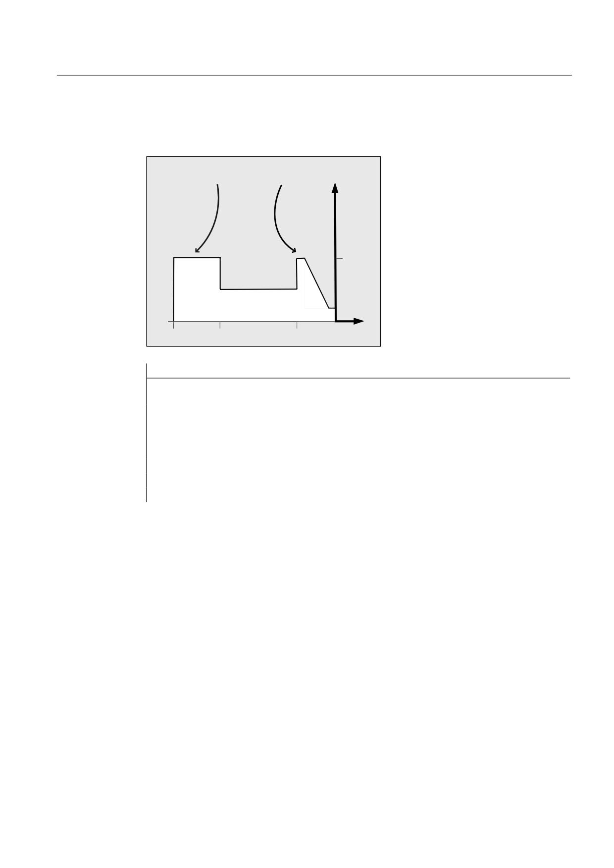
Tool offsets
7.2 Additive offsets
Example
The same cutting edge is used for 2 bearing seats:
/RFDWLRQ RI XVH
/RFDWLRQ RI XVH
;
' '/
'
=
Program code
Comments
N110 T7 D7
; The revolver is positioned to location 7. D7 and DL=1
are activated and moved through in the next block.
N120 G0 X10 Z1
N130 G1 Z-6
N140 G0 DL=2 Z-14
; DL=2 is activated in addition to D7 and is moved
through in the next block.
N150 G1 Z-21
N160 G0 X200 Z200
; Approach tool change position.
Job Planning
Programming Manual, 03/2010, 6FC5398-2BP20-1BA0
393

Tool offsets
7.2 Additive offsets
7.2.2
Specify wear and setup values ($TC_SCPxy[t,d], $TC_ECPxy[t,d])
Function
Wear and setting-up values can be read and written to using system variables. The logic is
based on the logic of the corresponding system variables for tools and tool noses.
System variables
System variable
Significance
$TC_SCPxy[<t>,<d>]
Wear values that are assigned to the particular geometry parameters
via xy, whereby x corresponds to the number of the wear value and
y establishes the reference to the geometry parameter.
$TC_ECPxy[<t>,<d>]
Setting-up values that are assigned to the particular geometry
parameter via xy, whereby x corresponds to the number of the
setting-up value and y establishes the reference to the geometry
parameter.
<t>: T number of the tool
<d>: D number of the tool cutting edge
Note
The defined wear and setup values are added to the geometry parameters and the other
offset parameters (D numbers).
Example
The wear value of length 1 is set to the value of 1.0 for the cutting edge <d> of tool <t>.
Parameter: $TC_DP3 (length 1, with turning tools)
Wear values: $TC_SCP13 to $TC_SCP63
Setup values: $TC_ECP13 to $TC_ECP63
$TC_SCP43 [<t>,<d>] = 1.0
Job Planning
394
Programming Manual, 03/2010, 6FC5398-2BP20-1BA0
Tool offsets
7.2 Additive offsets
7.2.3
Delete additive offsets (DELDL)
Function
The DELDL command deletes the additive offsets for the cutting edge of a tool (to release
memory space). Both the defined wear values and the setup values are deleted.
Syntax
DELDL[<t>,<d>]
DELDL[<t>]
DELDL
<Status>=DELDL[<t>,<d>]
Significance
DELDL
Command to delete additive offsets
<t>
T number of the tool
<d>
D number of the tool cutting edge
DELDL[<t>,<d>]
All additive offsets of the cutting edges <d> of the tool <t> are
deleted.
DELDL[<t>]
All additive offsets of all cutting edges of tool <t> are deleted.
DELDL
All additive offsets of all cutting edges of all tools of the TO unit are
deleted (for the channel in which the command is programmed).
<status>
Delete status
Value: Significance:
0
Deletion was successfully completed.
-
Offsets have not been deleted (if the parameter settings
specify exactly one tool edge), or not deleted completely (if
the parameter settings specify several cutting edges).
Note
Wear and setting-up values of active tools cannot be deleted (essentially the same as the
delete behavior of D or tool data).
Job Planning
Programming Manual, 03/2010, 6FC5398-2BP20-1BA0
395

Tool offsets
7.3 Special handling of tool offsets
7.3
Special handling of tool offsets
Function
The evaluation of the sign for tool length and wear can be controlled using setting data
SD42900 to SD42960.
The same applies to the behavior of the wear components when mirroring geometry axes or
changing the machining plane, and also to temperature compensation in tool direction.
Wear values:
If reference is made to wear values in the following, then this should be understood as the
sum of the actual wear values ($TC_DP12 to $TC_DP20) and the sum offsets with the wear
values ($SCPX3 to $SCPX11) and setting-up values ($ECPX3 to $ECPX11).
More information on summed offsets, refer to:
References:
Function Manual, Tool Management
Setting data
Setting Data
Significance
SD42900 $SC_MIRROR_TOOL_LENGTH
Mirroring of tool-length components and
components of the tool base dimension.
SD42910 $SC_MIRROR_TOOL_WEAR
Mirroring of wear values of the tool-length
components.
SD42920 $SC_WEAR_SIGN_CUTPOS
Evaluating the sign of the wear components as
a function of the tool nose position.
SD42930 $SC_WEAR_SIGN
Inverts the sign of wear dimensions.
SD42935 $SC_WEAR_TRANSFORM
Transformation of wear values.
SD42940 $SC_TOOL_LENGTH_CONST
Assignment of tool length components to
geometry axes.
SD42950 $SC_TOOL_LENGTH_TYPE
Assignment of the tool length components
independent of tool type.
SD42960 $SC_TOOL_TEMP_COMP
Temperature compensation value in tool
direction. Also operative when tool orientation is
programmed.
References
Function Manual Basic Functions; Tool Offset (W1)
Job Planning
396
Programming Manual, 03/2010, 6FC5398-2BP20-1BA0
Tool offsets
7.3 Special handling of tool offsets
Further Information
Activation of modified setting data
When the setting data described above are modified, the tool components are not
reevaluated until the next time a tool edge is selected. If a tool is already active and the data
of this tool are to be reevaluated, the tool must be selected again.
The same applies in the event that the resulting tool length is modified due to a change in
the mirroring status of an axis. The tool must be selected again after the mirror command, in
order to activate the modified tool-length components.
Orientable toolholders and new setting data
Setting data SD42900 to SD42940 have no effect on the components of an active toolholder
with orientation capability. However, the calculation with an orientable toolholder always
allows for a tool with its total resulting length (tool length + wear + tool base dimension). All
modifications initiated by the setting data are included in the calculation of the resulting total
length; i.e., vectors of the orientable toolholder are independent of the machining plane.
Note
When orientable toolholders are used, it is frequently practical to define all tools for a non-
mirrored basic system, even those which are only used for mirrored machining. When
machining with mirrored axes, the toolholder is then rotated such that the actual position of
the tool is described correctly. All tool-length components then automatically act in the
correct direction, dispensing with the need for control of individual component evaluation via
setting data, depending on the mirroring status of individual axes.
Further application options
The use of orientable toolholder functionality can also be useful if there is no physical option
of turning tools on the machine, even though tools with different orientations are permanently
installed. Tool dimensioning can then be performed uniformly in a basic orientation, where
the dimensions relevant for machining are calculated according to the rotations of a virtual
toolholder.
Job Planning
Programming Manual, 03/2010, 6FC5398-2BP20-1BA0
397
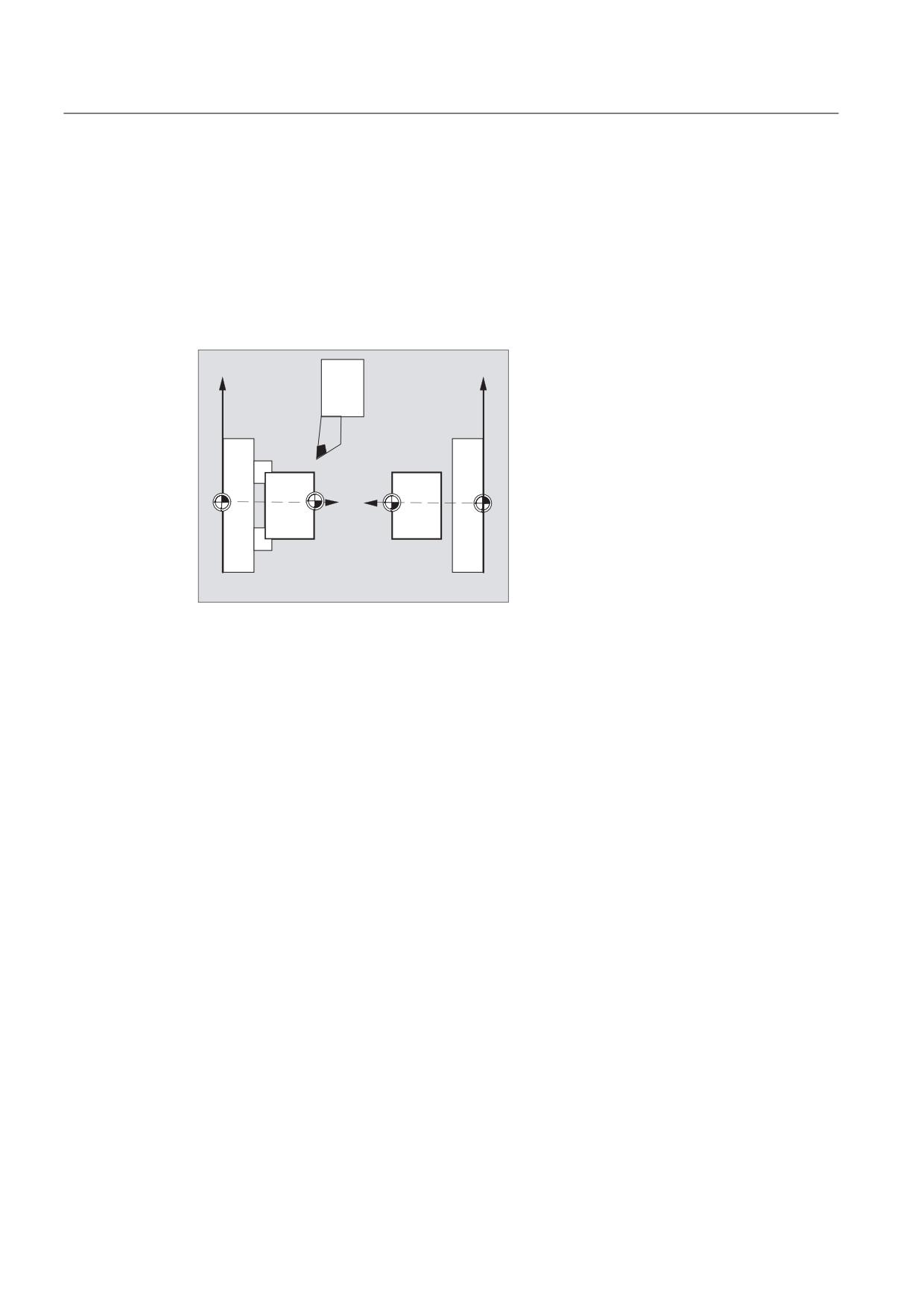
Tool offsets
7.3 Special handling of tool offsets
7.3.1
Mirroring of tool lengths
Function
When setting data SD42900 $SC_MIRROR_TOOL_LENGTH and
SD42910 $SC_MIRROR_TOOL_WEAR are not set to zero, then you can mirror the tool
length components and components of the basis dimensions with wear values and their
associated axes.
;
'
;
=
=
0
:
:
0
:&6
:&6
' ZLWK 6/
' ZLWK 6/
SD42900 $SC_MIRROR_TOOL_LENGTH
Setting data not equal to zero:
The tool length components ($TC_DP3, $TC_DP4 and $TC_DP5) and the components of
the basis dimensions ($TC_DP21, $TC_DP22 and $TC_DP23) are mirrored against their
associated axes, also mirrored - by inverting the sign.
The wear values are not mirrored. If these are also be be mirrored, then setting data
SD42910 $SC_MIRROR_TOOL_WEAR must be set.
SD42910 $SC_MIRROR_TOOL_WEAR
Setting data not equal to zero:
The wear values of the tool length components - whose associated axes are mirrored - are
also mirrored by inverting the sign.
Job Planning
398
Programming Manual, 03/2010, 6FC5398-2BP20-1BA0

Tool offsets
7.3 Special handling of tool offsets
7.3.2
Wear sign evaluation
Function
When setting data SD42920 $SC_WEAR_SIGN_CUTPOS and SD42930 $SC_WEAR_SIGN
are set not equal to zero, then you can invert the sign evaluation of the wear components.
SD42920 $SC_WEAR_SIGN_CUTPOS
Setting data not equal to zero:
For tools with the relevant tool nose position (turning and grinding tools, tool types 400), then
the sign evaluation of the wear components in the machining plane depends on the tool nose
position. This setting data is of no significance for tool types without relevant tool nose
position.
In the following table, the dimensions, whose sign is inverted using SD42920 (not equal to
zero), are designed using an X:
Tool nose position
Length 1
Length 2
1
2
X
3
X
X
4
X
5
6
7
X
8
X
9
Note
The sign evaluation using SD42920 and SD42910 are independent of one another. If e.g.
the the sign of a dimension is changed using both setting data, then the resulting sign
remains unchanged.
SD42930 $SC_WEAR_SIGN
Setting data not equal to zero:
Inverts the sign of all wear dimensions. This affects both the tool length and other variables
such as tool radius, rounding radius, etc.
If a positive wear dimension is entered, the tool becomes "shorter" and "thinner", refer to
Chapter "tool offset, special handling", activating changed setting data".
Job Planning
Programming Manual, 03/2010, 6FC5398-2BP20-1BA0
399
Tool offsets
7.3 Special handling of tool offsets
7.3.3
Coordinate system of the active machining operation (TOWSTD, TOWMCS,
TOWWCS, TOWBCS, TOWTCS, TOWKCS)
Function
Depending on the kinematics of the machine or the availability of an orientable toolholder,
the wear values measured in one of these coordinate systems are converted or transformed
to a suitable coordinate system.
Coordinate systems of active machining operation
The following coordinate systems can produce tool length offsets that can be used to
incorporate the tool length component "wear" into an active tool via the corresponding G
code of Group 56.
● Machine coordinate system (MCS)
● Basic coordinate system (BCS)
● Workpiece coordinate system (WCS)
● Tool coordinate system (TCS)
● Tool coordinate system of kinematic transformation (KCS)
Syntax
TOWSTD
TOWMCS
TOWWCS
TOWBCS
TOWTCS
TOWKCS
Significance
TOWSTD
Initial setting value for offsets in tool length wear value
TOWMCS
Offsets in tool length in MCS
TOWWCS
Offsets in tool length in WCS
TOWBCS
Offsets in tool length in BCS
TOWTCS
Offsets of tool length at toolholder reference point (orientable toolholder)
TOWKCS
Offsets of tool length at tool head (kinematic transformation)
Job Planning
400
Programming Manual, 03/2010, 6FC5398-2BP20-1BA0

Tool offsets
7.3 Special handling of tool offsets
Further Information
Distinguishing features
The most important distinguishing features are shown in the following table:
G code
Wear value
Active orientable toolholder
TOWSTD
Initial value, tool length
Wear values are subject to rotation.
TOWMCS
Wear value in MCS. TOWMCS is
It only rotates the vector of the
identical to TOWSTD if a tool holder
resultant tool length without taking
that can be orientated is not active.
into account the wear.
TOWWCS
The wear value is converted to the
The tool vector is calculated as for
MCS in the WCS.
TOWMCS without taking into account
the wear.
TOWBCS
The wear value is converted to the
The tool vector is calculated as for
MCS in the BCS.
TOWMCS without taking into account
the wear.
TOWTCS
The wear value is converted to the
The tool vector is calculated as for
MCS in the workpiece coordinate
TOWMCS without taking into account
system.
the wear.
TOWWCS , TOWBCS, TOWTCS: The wear vector is added to the tool vector.
Linear transformation
The tool length can be defined meaningfully in the MCS only if the MCS is generated by
linear transformation from the BCS.
Non-linear transformation
For example, if with TRANSMIT a non-linear transformation is active, then when specifying
the MCS as requested coordinate system, BCS is automatically used.
No kinematic transformation and no orientable toolholder
If neither a kinematic transformation nor an orientable toolholder is active, then all the other
four coordinate systems (except for the WCS) are combined. It is then only the WCS, which
is different to the other systems. Since only tool lengths need to be evaluated, translations
between the coordinate systems are irrelevant.
References:
For more information on tool compensation, see:
Function Manual Basic Functions; Tool Offset (W1)
Job Planning
Programming Manual, 03/2010, 6FC5398-2BP20-1BA0
401
Tool offsets
7.3 Special handling of tool offsets
Inclusion of wear values in calculation
The setting data SD42935 $SC_WEAR_TRANSFORM defines which of the three wear
components:
● Wear
● Total offsets fine
● Total offsets coarse
should be subject to a rotation using adapter transformation or a tool holder that can be
orientated if one of the following G codes is active:
● TOWSTD Default setting
For offsets in the tool length
● TOWMCS wear values
In the machine coordinate system (MCS)
● TOWWCS wear values
In the workpiece coordinate system (WCS)
● TOWBCS wear values (BCS)
In the basic coordinate system
● TOWTCS wear values in the tool coordinate system at the tool holder reference (T tool
holder reference)
● TOWKCS Wear values in the coordinate system of the tool head for kinematic transformation
Note
Evaluation of individual wear components (assignment to geometry axes, sign evaluation)
is influenced by:
• The active plane
• The adapter transformation
• Following setting data:
- SD42910 $SC_MIRROW_TOOL_WEAR
- SD42920 $SC_WEAR_SIGN_CUTPOS
- SD42930 $SC_WEAR_SIGN
- SD42940 $SC_TOOL_LENGTH_CONST
- SD42950 $SC_TOOL_LENGTH_TYPE
Job Planning
402
Programming Manual, 03/2010, 6FC5398-2BP20-1BA0

Tool offsets
7.3 Special handling of tool offsets
7.3.4
Tool length and plane change
Function
When setting data SD42940 $SC_TOOL_LENGTH_CONST is set not equal to zero, then
you can assign the tool length components - such as lengths, wear and basic dimension - to
the geometry axes for turning and grinding tools when changing the plane.
SD42940 $SC_TOOL_LENGTH_CONST
Setting data not equal to zero:
The assignment of tool length components (length, wear and tool base dimension) to
geometry axes does not change when the machining plane is changed (G17 - G19).
The following table shows the assignment of tool length components to geometry axes for
turning and grinding tools (tool types 400 to 599):
Content
Length 1
Length 2
Length 3
17
Y
X
Z
*)
X
Z
Y
19
Z
Y
X
-17
X
Y
Z
-18
Z
X
Y
-19
Y
Z
X
*)
Each value not equal to 0, which is not equal to one of the six listed values, is evaluated as value
18.
The following table shows the assignment of tool length components to geometry axes for all
other tools (tool types < 400 or > 599):
Operating plane
Length 1
Length 2
Length 3
*)
Z
Y
X
18
Y
X
Z
19
X
Z
Y
-17
Z
X
Y
-18
Y
Z
X
-19
X
Y
Z
*)
Each value not equal to 0, which is not equal to one of the six listed values, is evaluated as value
17.
Note
For representation in tables, it is assumed that geometry axes up to 3 are designated with X,
Y, Z. The axis order and not the axis identifier determines the assignment between a
compensation and an axis.
Job Planning
Programming Manual, 03/2010, 6FC5398-2BP20-1BA0
403
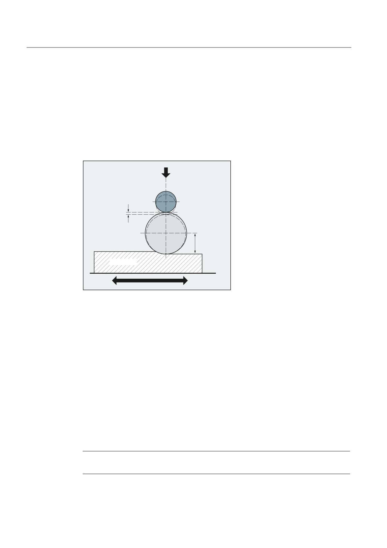
Tool offsets
7.4 Online tool offset (PUTFTOCF, FCTDEF, PUTFTOC, FTOCON, FTOCOF)
7.4
Online tool offset (PUTFTOCF, FCTDEF, PUTFTOC, FTOCON,
FTOCOF)
Function
When the "Online tool offset" function is active, a tool length offset resulting from the
machining is applied immediately on grinding tools.
An application example is CD dressing, where the grinding wheel is dressed in parallel to
machining.
'UHVVLQJ UROO
'UHVVLQJ DPRXQW
*ULQGLQJ GLVF
OHQJWK
WR EH
FRUUHFWHG
:RUNSLHFH
The tool length offset can be changed from the machining channel or a parallel channel
(dresser channel).
The online tool offset is written using various functions dependent on the timing of the
dressing process:
● Continuous write, non-modal (PUTFTOCF)
With PUTFTOCF, dressing is carried out at the same time as machining.
The tool offset is changed continuously in the machining channel according to a
polynomial function of the first, second or third order, which must have been defined
previously with FCTDEF.
PUTFTOCF is always non-modal; in other words, it takes effect in the subsequent traversing
block.
● Continuous write, modal: ID=1 DO FTOC (see "Online tool offset (FTOC) (Page 593)")
● Discrete write (PUTFTOC)
With PUTFTOC, dressing is not carried out at the same time as machining from a parallel
channel. The offset value specified with PUTFTOC takes effect immediately in the
destination channel.
Note
Online tool offset can be applied only to grinding tools.
Job Planning
404
Programming Manual, 03/2010, 6FC5398-2BP20-1BA0
Tool offsets
7.4 Online tool offset (PUTFTOCF, FCTDEF, PUTFTOC, FTOCON, FTOCOF)
Syntax
Activate/deactivate online tool offset in the destination channel:
FTOCON
FTOCOF
Write online tool offset:
● Continuous, non-modal:
FCTDEF(<function>,<LLimit>,<ULimit>,<a0>,<a1>,<a2>,<a3>)
PUTFTOCF(<function>,<reference value>,<tool parameter>,<channel>,<spindle>)
● Discrete:
PUTFTOC(<offset value>,<tool parameter>,<channel>,<spindle>)
Significance
FTOCON:
Activate online tool offset
FTOCON must be written in the channel in which the online tool offset is to
take effect.
FTOCOF:
Cancel online tool offset
With FTOCOF, the offset is no longer applied; however, the complete value
written with PUTFTOC is corrected in the cutting-edge-specific offset data.
Note:
In order to definitively deactivate the online tool offset, the tool (T...) still
needs to be selected/deselected after FTOCOF.
FCTDEF:
FCTDEF is used to define the polynomial function for PUTFTOCF.
Parameter:
<function>:
Number of the polynomial function
Type: INT
<LLimit>:
Lower limit value
Type: REAL
<ULimit>:
Upper limit value
Type: REAL
<a0> ... <a3>:
Coefficients of polynomial function
Type: REAL
Job Planning
Programming Manual, 03/2010, 6FC5398-2BP20-1BA0
405