SINUMERIK 840D sl/828D. Job Planning. Programming Manual (2010-2018) - page 17
Flexible NC programming
1.25 Subprogram technique
Example: both cycles
Display screen for cycle MY_CYCLE_1
3DUDPHWHU RI WKH F\FOH
,QWHJHU YDOXH
&KDUDFWHU SDUDPHWHU
6XEURXWLQHV
Display screen for cycle SPECIAL CYCLE
7RWDO OHQJWK
0DFKLQLQJ W\SH
Syntax description for the uc.com file - user cycle description
Header line for each cycle:
as in the cov.com file preceded by "//"
//C <number> (<cycle_name>) comment_text
Example:
//C25(MY_CYCLE_1) usercycle_
Line for description for each parameter:
(<data_type_id> / <minimum_value> <maximum_value>
/ <preset_value> /
Job Planning
Programming Manual, 03/2010, 6FC5398-2BP20-1BA0
199
Flexible NC programming
1.25 Subprogram technique
Data type identifier:
R
for real
I
for integer
C
for character (1 character)
S
for string
Minimum value, maximum value (can be omitted)
Limitations of the entered values which are checked at input; values outside this range
cannot be entered. It is possible to specify an enumeration of values which can be operated
via the toggle key; they are listed preceded by "*", other values are then not permissible.
Example:
(I/*123456/1/Machining type)
There are no limits for string and character types.
Default value (can be omitted)
Value which is the default value in the corresponding screen when the cycle is called; it can
be changed via operator input.
Comment
Text of up to 50 characters which is displayed in front of the parameter input field in the call
screen for the cycle.
Job Planning
200
Programming Manual, 03/2010, 6FC5398-2BP20-1BA0
Flexible NC programming
1.26 Macro technique (DEFINE ... AS)
1.26
Macro technique (DEFINE ... AS)
CAUTION
Use of macros can significantly alter the control's programming language! Therefore,
exercise caution when using macros.
Function
A macro is a sequence of individual statements, which have together been assigned a name
of their own. G, M and H functions or L subprogram names can also be used as macros.
When a macro is called during a program run, the statements programmed under the
program name are executed one after the other.
Application
Instruction sequences that are repeated are only programmed once as macro in a dedicated
macro block (macro file) or once at the beginning of the program. The macro can then be
called in any main program or subprogram and executed.
Activating
In order to use the macros of a macro file in the NC program, the macro file must be
downloaded into the NC.
Syntax
Macro definition:
DEFINE <Macro name> AS <instruction 1> <instruction 2> ...
Call in the NC program:
<macro name>
Significance
DEFINE ... AS :
Keyword combination to define a macro
<macro name>:
Macro name
Only identifiers are permissible as macro names.
The macro is called from the NC program using the macro name.
<operation>:
Programming instruction that should be included in the macro.
Job Planning
Programming Manual, 03/2010, 6FC5398-2BP20-1BA0
201

Flexible NC programming
1.26 Macro technique (DEFINE ... AS)
Rules when defining a macro
● Any identifier, G, M, H functions and L program names can be defined in a macro.
● Macros can also be defined in the NC program.
● G function macros can only be defined in the macro module globally for the entire control
(modal).
● H and L functions can be programmed with 2 digits.
● M and G functions can be programmed using 3 digits.
CAUTION
Keywords and reserved names may not be re-defined using macros.
General conditions
Nesting of macros is not possible.
Examples
Example 1: Macro definition at the beginning of the program
Program code
Comments
DEFINE LINE AS G1 G94 F300
; Macro definition
N70 LINE X10 Y20
; Macro call
Example 2: Macro definitions in a macro file
Program code
Comments
DEFINE M6 AS L6
; A subprogram is called at tool change to handle
the necessary data transfer. The actual M
function is output in the subprogram (e.g.,
M106).
DEFINE G81 AS DRILL(81)
; Emulation of the DIN-G function.
DEFINE G33 AS M333 G333
; During thread cutting synchronization is
requested with the PLC. The original G function
G33 was renamed to G333 by machine data so that
the programming is identical for the user.
Job Planning
202
Programming Manual, 03/2010, 6FC5398-2BP20-1BA0
Flexible NC programming
1.26 Macro technique (DEFINE ... AS)
Example 3: External macro file
The macro file must be downloaded into the NC after reading-in the external macro file into
the control. Only then can macros be used in the NC program.
Program code
Comments
%_N_UMAC_DEF
;$PATH=/_N_DEF_DIR
; Customer-specific macros
DEFINE PI AS 3.14
DEFINE TC1 AS M3 S1000
DEFINE M13 AS M3 M7
; Spindle clockwise, coolant on
DEFINE M14 AS M4 M7
; Spindle counterclockwise, coolant on
DEFINE M15 AS M5 M9
; Spindle stop, coolant off
DEFINE M6 AS L6
; Call tool change program
DEFINE G80 AS MCALL
; Deselect drilling cycle
M30
Job Planning
Programming Manual, 03/2010, 6FC5398-2BP20-1BA0
203
Flexible NC programming
1.26 Macro technique (DEFINE ... AS)
Job Planning
204
Programming Manual, 03/2010, 6FC5398-2BP20-1BA0
File and Program Management
2
2.1
Program memory
Function
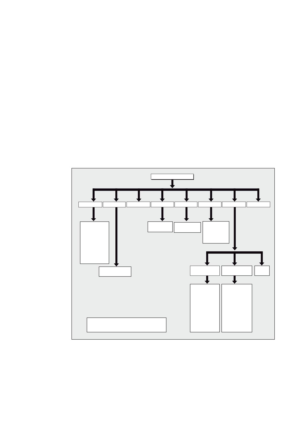
Files and programs (e.g. main programs and subprograms, macro definitions) are saved in
the non-volatile program memory (→ passive file system).
References:
Function Manual, Extended Functions; Memory Configuration (S7)
A number of file types are also stored here temporarily; these can be transferred to the work
memory as required (e.g. for initialization purposes when machining a specific workpiece).
3URJUDP PHPRU\
B1B'()B',5
B1B&67B',5
B1B&0$B',5
B1B&86B',5
B1B63)B',5
B1B03)B',5
B1B:.6B',5
B1B&20B',5
B1B60$&B'()
B1B/
B63)
B1B*/2%B63)
B1B03) B03)
B1B00$&B'()
B1B B63)
B1B B63)
B1B029B03)
B1B80$&B'()
B1B B03)
B1B6*8'B'()
B1B
B1B0*8'B'()
B1B8*8'B'()
B1B*8' B'()
B1B*8' B'()
B1B32&.(7 B63)
B1B:(//(B:3'
B1B03)
B:3'
B1B B63)
B1B:(//(B03)
B1B03)
B03)
B1B3$57 B03)
B1B/ B63)
B1B3$57 B63)
B1B B
B1B3$57 B63)
B1B:(//(B,1,
B1B:(//(B6($
B1B3$57 B,1,
B1B3$57 B8)5
%ODFN QDPHV 3HUPDQHQWO\ DVVLJQHG
B1B3$57 B&20
*UD\ QDPHV $VVLJQHG E\ WKH XVHU
B1B:(//(
Job Planning
Programming Manual, 03/2010, 6FC5398-2BP20-1BA0
205

File and Program Management
2.1 Program memory
Standard directories
Its standard complement of directories is as follows:
Folder
Contents
_N_DEF_DIR
Data modules and macro modules
_N_CST_DIR
Standard cycles
_N_CMA_DIR
Manufacturer cycles
_N_CUS_DIR
User cycles
_N_WKS_DIR
Workpieces
_N_SPF_DIR
Global subprograms
_N_MPF_DIR
Main programs
_N_COM_DIR
Comments
File types
The following file types can be stored in the main memory:
File type
Description
name_MPF
Main program
name_SPF
Subprogram
name_TEA
Machine data
name_SEA
Setting data
name_TOA
Tool offsets
name_UFR
Zero offsets/frames
name_INI
Initialization files
name_GUD
Global user data
name_RPA
R parameters
name_COM
Comment
name_DEF
Definitions for global user data and macros
Workpiece main directory (_N_WKS_DIR)
The workpiece main directory exists in the standard setup of the program memory under the
name _N_WKS_DIR. The workpiece main directory contains all the workpiece directories for the
workpieces that you have programmed.
Job Planning
206
Programming Manual, 03/2010, 6FC5398-2BP20-1BA0

File and Program Management
2.1 Program memory
Workpiece directories (..._WPD)
To make data and program handling more flexible certain data and programs can be
grouped together or stored in individual workpiece directories.
A workpiece directory contains all files required for machining a workpiece. These can be
main programs, subprograms, any initialization programs and comment files.
The first time a part program is started, initialization programs are executed once, depending
on the selected program (in accordance with machine data MD11280
$MN_WPD_INI_MODE).
Example:
The workpiece directory _N_WELLE_WPD, created for SHAFT workpiece contains the
following files:
File
Significance
_N_SHAFT_MPF
Main program
_N_PART2_MPF
Main program
_N_PART1_SPF
Subprogram
_N_PART2_SPF
Subprogram
_N_SHAFT_INI
General initialization program for the data of the workpiece
_N_SHAFT_SEA
Setting data initialization program
_N_PART2_INI
General initialization program for the data for the Part 2 program
_N_PART2_UFR
Initialization program for the frame data for the Part 2 program
_N_SHAFT_COM
Comment file
Creating workpiece directories on an external PC
The steps described below are performed on an external data station. Please refer to your
Operator's Guide for file and program management (from PC to control system) directly on
the control.
Creating a workpiece directory with a path name ($PATH=…)
The destination path $PATH=… is specified within the second line of the file. The file is then
stored at the specified path.
Example:
Program code
%_N_SHAFT_MPF
;$PATH=/_N_WKS_DIR/_N_SHAFT_WPD
N40 G0 X… Z…
M2
File _N_WELLE_MPF is stored in directory /_N_WKS_DIR/_N_WELLE_WPD.
Job Planning
Programming Manual, 03/2010, 6FC5398-2BP20-1BA0
207
File and Program Management
2.1 Program memory
Creating a workpiece directory without a path name
If the path name is missing, files with the _SPF extension are stored in directory
/_N_SPF_DIR, files with the _INI extension are stored in the RAM and all other files are
stored in directory/_N_MPF_DIR.
Example:
Program code
%_N_SHAFT_SPF
M17
File _N_WELLE_SPF is stored in directory /_N_SPF_DIR.
Select workpiece for machining
A workpiece directory can be selected for execution in a channel. If a main program with the
same name or only a single main program (_MPF) is stored in this directory, this is
automatically selected for execution.
References:
/BAD/ Operating Manual HMI Advanced; "Job list" and "Selecting a program for execution"
Search paths for subprogram call
If the search path is not specified explicitly in the part program when a subprogram (or
initialization file) is called, the calling program searches in a fixed search path.
Subprogram call with absolute path
Example
Program code
CALL"/_N_CST_DIR/_N_CYCLE1_SPF"
Subprogram call without absolute path
Programs are usually called without specifying a path.
Example
Program code
CYCLE1
Job Planning
208
Programming Manual, 03/2010, 6FC5398-2BP20-1BA0
File and Program Management
2.1 Program memory
The directories are searched for the called program in the following sequence:
No.
Folder
Significance
1
Current directory / name
Workpiece main directory or standard
directory _N_MPF_DIR
2
Current directory / name_SPF
3
Current directory / name_MPF
4
/_N_SPF_DIR / name_SPF
Global subprograms
5
/_N_CUS_DIR / name_SPF
User cycles
6
/_N_CMA_DIR / name_SPF
Manufacturer cycles
7
/_N_CST_DIR / name_SPF
Standard cycles
Programming search paths for subprogram call (CALLPATH)
The CALLPATH part program command is used to extend the search path of a subprogram
call.
Example:
Program code
CALLPATH ("/_N_WKS_DIR/_N_MYWPD_WPD")
The search path is stored in front of position 5 (user cycle) in accordance with the specified
programming.
For further information about the programmable search path for subprogram calls with
CALLPATH, see chapter "Extending the search path for subprogram calls with CALLPATH".
Job Planning
Programming Manual, 03/2010, 6FC5398-2BP20-1BA0
209

File and Program Management
2.2 Working memory (CHANDATA, COMPLETE, INITIAL)
2.2
Working memory (CHANDATA, COMPLETE, INITIAL)
Function
The working memory contains the current system and user data with which the control is
operated (active file system), e.g.:
● Active machine data
● Tool offset data
● Work offsets
● ...
Initialization programs
These are programs with which the working memory data are initialized. The following file
types can be used for this:
File type
Significance
name_TEA
Machine data
name_SEA
Setting data
name_TOA
Tool offsets
name_UFR
Zero offsets/frames
name_INI
Initialization files
name_GUD
Global user data
name_RPA
R parameters
You will fine information on all of the file types in the Operator Manual for the operator
interface.
Data areas
The data can be organized in different areas in which they are to apply. For example, a
control can have several channels or, as is commonly the case, several axes at its disposal.
The following exist:
Identifier
Data areas
NCK
NCK-specific data
CH<n>
Channel-specific data (<n> specifies the channel name)
AX<n>
Axis-specific data (<n> specifies the number of the machine axis)
TO
Tool data
COMPLETE
All data
Job Planning
210
Programming Manual, 03/2010, 6FC5398-2BP20-1BA0

File and Program Management
2.2 Working memory (CHANDATA, COMPLETE, INITIAL)
Create initialization program at an external PC
The data area identifier and the data type identifier can be used to determine the areas,
which are to be treated as a unit when the data are saved:
_N_AX5_TEA_INI
Machine data for axis 5
_N_CH2_UFR_INI
Frames of channel 2
_N_COMPLETE_TEA_INI
All machine data
When the control is started up initially, a set of data is automatically loaded to ensure proper
operation of the control.
Procedure for multi-channel controls (CHANDATA)
CHANDATA(<channel number>) for several channels is only permissible in the file
_N_INITIAL_INI. This is the commissioning file with which all data of the control is initialized.
Program code
Comments
%_N_INITIAL_INI
CHANDATA(1)
; Machine axis assignment, channel 1:
$MC_AXCONF_MACHAX_USED[0]=1
$MC_AXCONF_MACHAX_USED[1]=2
$MC_AXCONF_MACHAX_USED[2]=3
CHANDATA(2)
; Machine axis assignment, channel 2:
$MC_AXCONF_MACHAX_USED[0]=4
$MC_AXCONF_MACHAX_USED[1]=5
CHANDATA(1)
; Axial machine data:
; Exact stop window coarse:
$MA_STOP_LIMIT_COARSE[AX1]=0.2
; Axis 1
$MA_STOP_LIMIT_COARSE[AX2]=0.2
; Axis 2
; ;Exact stop window fine:
$MA_STOP_LIMIT_FINE[AX1]=0.01
; Axis 1
$MA_STOP_LIMIT_FINE[AX1]=0.01
; Axis 2
CAUTION
CHANDATA statement
In the part program, the CHANDATA instruction may only be set for that channel in which the
NC program is executed; i.e. the instruction can be used to protect NC programs so that
they are not executed in the wrong channel.
Program processing is aborted if an error occurs.
Job Planning
Programming Manual, 03/2010, 6FC5398-2BP20-1BA0
211

File and Program Management
2.2 Working memory (CHANDATA, COMPLETE, INITIAL)
Note
INI files in job lists do not contain any CHANDATA instructions.
Save initialization program (COMPLETE, INITIAL)
The files of the working memory can be saved on an external PC and then read in again
from there.
● The files are saved with COMPLETE.
● INITIAL is used to create an INI file (_N_INITIAL_INI) over all areas.
Read-in initialization program
NOTICE
If the file is read-in with the name "INITIAL_INI", then all data that are not supplied in the file
are initialized using standard data. Only machine data are an exception. This means that
setting data, tool data, ZO, GUD values, ... are supplied with standard data (normally
"ZERO").
For example, the file COMPLETE_TEA_INI is suitable for reading-in individual machine data.
The control only expects machine data in this file. This is the reason that the other data
areas remain unaffected in this case.
Loading initialization programs
The INI programs can also be selected and called as part programs if they only use data of
one channel. This means that it is also possible to initialize program controlled data.
Job Planning
212
Programming Manual, 03/2010, 6FC5398-2BP20-1BA0
File and Program Management
2.3 Structuring instruction in step editor (SEFORM)
2.3
Structuring instruction in step editor (SEFORM)
Function
The structuring instruction SEFORM is evaluated in the step editor (editor-based program
support) to generate the step view for HMI Advanced. The step view is used to improve the
readability of the NC subprogram.
Syntax
SEFORM(<section name>,<level>,<icon>)
Significance
SEFORM()
Function call of the structuring instruction with parameters
<section name>, <level> and <icon>
<section name>
Identifier of the working step
Type:
STRING
<level>
Index for the main or sub-level
Type:
INT
Value:
0
Main level
1, ..., <n>
Lower level 1, ... , lower level <n>
<icon>
Name of the icon displayed for this section.
Type:
STRING
Note
SEFORM instructions are generated in the Step editor.
The string transferred with the <section name> parameter is stored main-run-synchronously
in the OPI variable in a similar way to the MSG instruction. The information remains until
overwritten by the next SEFORM instruction. Reset and end of part program clear the content.
The NCK checks during the part program execution the parameters <level> and <icon> but
does not process them any further.
References
For additional information on editor-based program support, see:
Operating Manual HMI Advanced.
Job Planning
Programming Manual, 03/2010, 6FC5398-2BP20-1BA0
213
File and Program Management
2.3 Structuring instruction in step editor (SEFORM)
Job Planning
214
Programming Manual, 03/2010, 6FC5398-2BP20-1BA0
Protection zones
3
3.1
Definition of the protection zones (CPROTDEF, NPROTDEF)
Function
You can use protection zones to protect various elements on the machine, their components
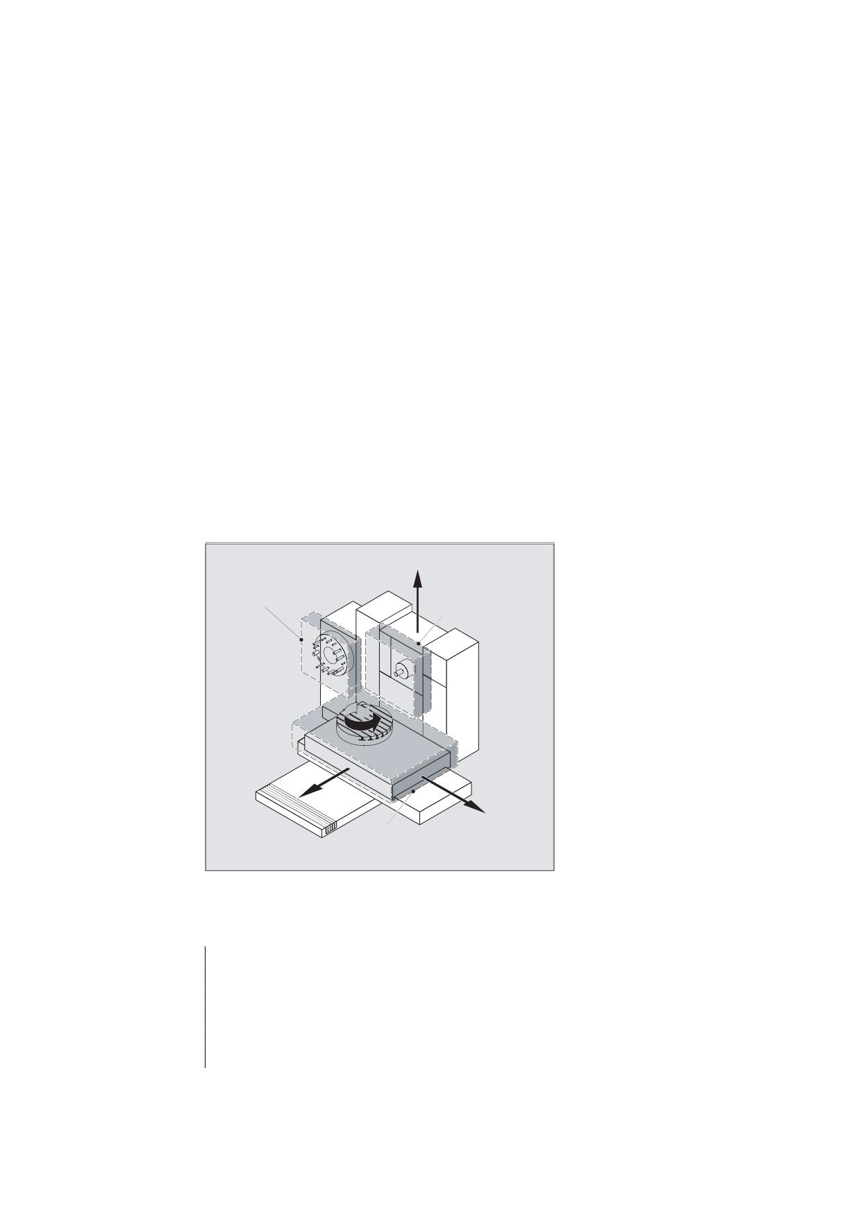
and the workpiece against incorrect movements.
Tool-oriented protection zones:
For parts that belong to the tool (e.g. tool, toolholder)
Workpiece-oriented protection zones:
For parts that belong to the workpiece (e.g. parts of the workpiece, clamping table, clamping
shoe, spindle chuck, tailstock).
7RRO UHODWHG
<
7RRO UHODWHG
SURWHFWLRQ ]RQH
SURWHFWLRQ ]RQH
%
=
;
:RUNSLHFH UHODWHG
SURWHFWLRQ ]RQH
Syntax
DEF INT NOT_USED
G17/G18/G19
CPROTDEF/NPROTDEF(<n>,<t>,<applim>,<applus>,<appminus>)
G0/G1/... X/Y/Z
EXECUTE(NOT_USED)
Job Planning
Programming Manual, 03/2010, 6FC5398-2BP20-1BA0
215
Protection zones
3.1 Definition of the protection zones (CPROTDEF, NPROTDEF)
Meaning
DEF INT NOT_USED:
Define local variable, data type INTEGER
(see Chapter "Motion synchronous actions (Page 551)")
G17/G18/G19:
The required plane is selected before CPROTDEF or NPROTDEF
with G17/G18/G19 and must not be altered before EXECUTE. The
applicate must not be programmed between CPROTDEF or
NPROTDEF and EXECUTE.
CPROTDEF:
Define channel-specific protection zones (for NCU 572/573
only)
NPROTDEF:
Defining machine-specific protection zones
G0/G1/... X/Y/Z
The contour of the protection zones is specified with up to 11
... :
traversing movements in the selected plane. The first
traversing movement is the movement to the contour. The
valid protection zone is the zone left of the contour.
Note:
The travel motion programmed between CPROTDEF or NPROTDEF
and EXECUTE are not executed, but merely define the protection
area.
EXECUTE:
End definition
<n>:
Number of defined protection zone
<t>
:
Type of protection zone
TRUE:
Tool-related protection zone
FALSE:
Workpiece-related protection zone
<applim>
:
Type of limitation in the third dimension
0:
No limitation
1:
Limit in plus direction
2:
Limit in minus direction
3:
Limit in positive and negative direction
<applus>:
Value of the limit in the positive direction in the 3rd dimension
<appminus>:
Value of the limit in the negative direction in the 3rd dimension
NOT_USED:
Error variable has no effect for protection zones with EXECUTE
General conditions
During definition of the protection zones:
● no cutter or tool nose radius compensation must be active.
● no transformation must be active.
● no frame must be active.
Neither must reference point approach (G74), fixed point approach (G75), block
preprocessing stop nor program end be programmed.
Job Planning
216
Programming Manual, 03/2010, 6FC5398-2BP20-1BA0
Protection zones
3.1 Definition of the protection zones (CPROTDEF, NPROTDEF)
Further information
Definition of protection zones
Definition of the protection zones includes the following:
● CPROTDEF for channel-specific protection zones
● NPROTDEF for machine-specific protection zones
● Contour description for protection zone
● Termination of the definition with EXECUTE
You can specify a relative offset for the reference point of the protection zone when the
protection zone is activated in the NC part program.
Reference point for contour description
The workpiece-oriented protection zones are defined in the basic coordinate system.
The tool-oriented protection zones are defined with reference to the tool carrier reference
point F.
Permissible contour elements
The following are permissible to define the contour of the protection zone:
● G0, G1 for straight contour elements
● G2 for clockwise circle segments (only for workpiece-oriented protection zones)
● G3 for circular segments in the counterclockwise direction
Note
If a full circle describes the protection zone, it must be divided into two half circles. The
sequence G2, G3 or G3, G2 is not permitted. A short G1 block must be inserted, if
necessary.
The last point in the contour description must coincide with the first.
External protection zones
External protection zones (only possible for workpiece-related protection zones) must be
defined in the clockwise direction.
Protection zones symmetrical around the center of rotation
For protection zones symmetrical around the axis or rotation (e.g. spindle chuck), you must
describe the complete contour and not only up to the center of rotation!
Job Planning
Programming Manual, 03/2010, 6FC5398-2BP20-1BA0
217
Protection zones
3.1 Definition of the protection zones (CPROTDEF, NPROTDEF)
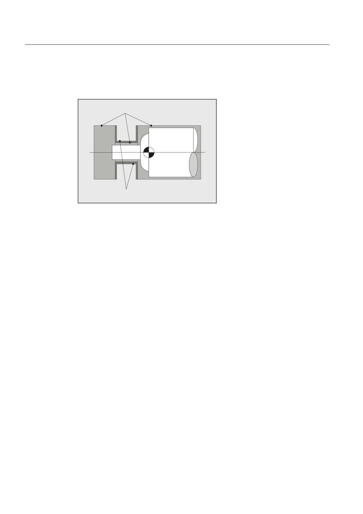
Tool-related protection zones
Tool-related protection zones must always be convex. If a concave protected zone is
desired, this should be subdivided into several convex protection zones.
&RQYH[ SURWHFWLRQ ]RQHV
)
&RQFDYH SURWHFWLRQ ]RQHV QRW SHUPLWWHG
Job Planning
218
Programming Manual, 03/2010, 6FC5398-2BP20-1BA0
Protection zones
3.2 Activating/deactivating protection zones (CPROT, NPROT)
3.2
Activating/deactivating protection zones (CPROT, NPROT)
Function
Activating and preactivating previously defined protection zones for collision monitoring and
deactivating protection zones.
The maximum number of protection zones, which can be active simultaneously on the same
channel, is defined in machine data.
If no tool-related protection zone is active, the tool path is checked against the workpiece-
related protection zones.
Note
If no workpiece-related protection zone is active, protection zone monitoring does not take
place.
Syntax
CPROT(<n>,<state>,<xMov>,<yMov>,<zMov>)
NPROT(<n>,<state>,<xMov>,<yMov>,<zMov>)
Meaning
CPROT:
Call channel-specific protection zone (for NCU 572/573 only)
NPROT:
Call machine-specific protection zone
<n>:
Number of the protection zone
<state>
:
Status parameter
0:
Deactivate protection zone
1:
Preactivate protection zone
2:
Activate protection zone
3:
Preactivate protection zone with conditional stop
<xMov>,<yMov>,<zMov>: Move defined protection zone on the geometry axes
General conditions
Protection zone monitoring for active tool radius compensation
For active tool radius compensation, a functioning protection zone monitoring is only
possible if the plane of the tool radius compensation is identical to the plane of the protection
zone definitions.
Job Planning
Programming Manual, 03/2010, 6FC5398-2BP20-1BA0
219
Protection zones
3.2 Activating/deactivating protection zones (CPROT, NPROT)
Example
Possible collision of a milling cutter with the measuring probe is to be monitored on a milling
machine. The position of the measuring probe is to be defined by an offset when the function
is activated. The following protection zones are defined for this:
● A machine-specific and a workpiece-related protection zone for both the measuring probe
holder (n-SB1) and the measuring probe itself (n-SB2).
● A channel-specific and a tool-oriented protection zone for the milling cutter holder (c-
SB1), the cutter shank (c-SB2) and the milling cutter itself (c-SB3).
The orientation of all protection zones is in the Z direction.
The position of the reference point of the measuring probe on activation of the function must
be X = -120, Y = 60 and Z = 80.
5HIHUHQFH SRLQW IRU
WKH SURWHFWLRQ ]RQH
RI WKH PHDVXULQJ SUREH
Q 6%
Q 6%
& 6%
& 6%
=
& 6%
<
;
Program code
Comment
DEF INT PROTECTB
; Definition of a Help variable
Definition of protection zone G17
; Set orientation
NPROTDEF(1,FALSE,3,10,-10)G01 X0 Y-10
; Protection zone n-SB1
X40
Y10
X0
Y-10
EXECUTE(PROTECTB)
Job Planning
220
Programming Manual, 03/2010, 6FC5398-2BP20-1BA0
Protection zones
3.2 Activating/deactivating protection zones (CPROT, NPROT)
Program code
Comment
NPROTDEF(2,FALSE,3,5,-5)
; Protection zone n-SB2
G01 X40 Y-5
X70
Y5
X40
Y-5
EXECUTE(PROTECTB)
CPROTDEF(1,TRUE,3,0,-100)
; Protection zone c-SB1
G01 X-20 Y-20
X20
Y20
X-20
Y-20
EXECUTE(PROTECTB)
CPROTDEF(2,TRUE,3,-100,-150)
; Protection zone c-SB2
G01 X0 Y-10
G03 X0 Y10 J10
X0 Y-10 J-10
EXECUTE(PROTECTB)
CPROTDEF(3,TRUE,3,-150,-170)
; Protection zone c-SB3
G01 X0 Y-27,5
G03 X0 Y27,5 J27,5
X0 Y27,5 J-27,5
EXECUTE(PROTECTB)
Activation of protection zones:
NPROT(1,2,-120,60,80)
; Activate protection zone n-SB1 with
offset
NPROT(2.2,-120,60,80)
; Activate protection zone n-SB2 with
offset
CPROT(1,2,0,0,0)
; Activate protection zone c-SB1 with
offset
CPROT(2,2,0,0,0)
; Activate protection zone c-SB2 with
offset
CPROT(3,2,0,0,0)
; Activate protection zone c-SB3 with
offset
Job Planning
Programming Manual, 03/2010, 6FC5398-2BP20-1BA0
221
Protection zones
3.2 Activating/deactivating protection zones (CPROT, NPROT)
Further information
Activation status (<state>)
● <state>=2
A protection zone is generally activated in the part program with status = 2.
The status is always channel-specific even for machine-oriented protection zones.
● <state>=1
If a PLC user program provides for a protection zone to be effectively set by a PLC user
program, the required preactivation is implemented with status = 1.
● <state>=3
In the case of preactivation with conditional stop, the system never stops in front of a
preactivated protection zone which has been violated. The stop only occurs if the
protection zone has been activated. This facilitates uninterrupted processing if the
protection zones have only been activated in special cases. N.B. The system may move
into the protection zone as a result of the braking ramp if the protection zone is only
activated immediately prior to motion.
Preactivation with conditional stop is realized using status = 3.
● <state>=0
The protection zones are deactivated and therefore disabled with Status = 0. No shift is
required.
Movement of protection zones for (pre)activating
The offset can take place in 1, 2, or 3 dimensions. The offset refers to:
● the machine zero in workpiece-specific protection zones.
● the tool carrier reference point F in tool-specific protection zones.
Status after booting
Protection zones can be activated straight after booting and subsequent reference point
approach. The system variable $SN_PA_ACTIV_IMMED[<n>] or
$SC_PA_ACTIV_IMMED[<n>] must be set to TRUE for this purpose. They are always
activated with Status = 2 and have no offset.
Multiple activation of protection zones
A protection zone can be active simultaneously in several channels (e.g. tailstock where
there are two opposite sides). The protection zones are only monitored if all geometry axes
have been referenced.
The following applies:
● The protection zone cannot be activated simultaneously with different offsets in a single
channel.
● Machine-oriented protection zones must have the same orientation on both channels.
Job Planning
222
Programming Manual, 03/2010, 6FC5398-2BP20-1BA0
Protection zones
3.3 Checking for protection zone violation, working area limitation and software limits (CALCPOSI)
3.3
Checking for protection zone violation, working area limitation and
software limits (CALCPOSI)
Function
The CALCPOSI function is for checking whether, starting from a defined starting point, the
geometry axes can traverse a defined path without violating the axis limits (software limits),
working area limitations, or protection zones.
If the defined path cannot be traversed, the maximum permissible path is returned.
The CALCPOSI function is a predefined subprogram. It must be alone in a block.
Syntax
Status=CALCPOSI(_STARTPOS, _MOVDIST, _DLIMIT, _MAXDIST, _BASE_SYS, _TESTLIM)
Significance
Status
0: Function OK,
the specified path can be completely traversed.
-: At least one component is negative in _DLIMIT
-: An error has occurred in a transformation calculation
If the specified path cannot be completely traversed, then a
positive, decimal-coded value is returned:
Units digit (type of violated limit):
1: Software limits are limiting the traversing path.
2: Working area limits are limiting the traversing path.
3: Software limits are limiting the traversing path.
If several limits are violated simultaneously (e.g. software
limits and protection zones), the limit that results in the most
significant restriction in the specified traversing path is
indicated in the units digit.
Job Planning
Programming Manual, 03/2010, 6FC5398-2BP20-1BA0
223
Protection zones
3.3 Checking for protection zone violation, working area limitation and software limits (CALCPOSI)
Tens digit
10:
The initial value violates the limit
20:
The specified straight line violates the limit. This value is also
returned if the end point does not violate any limit itself but
the path from the starting point to the end point would cause
a limit value to be violated (e.g. by passing through a
protection zone, curved software limits in the WCS for non-
linear transformations, e.g. transmit).
Hundreds digit
100:
The positive limit value is violated (only if the units digit is 1 or
2, i.e. for software limits and working area limits)
100:
An NCK protection zone is violated (only if the units digit is 3).
200:
The negative limit value is violated (only if the units digit is 1
or 2, i.e. for software limits and working area limits)
200:
A channel-specific protection zone is violated (only if the units
digit is 3).
Thousands digit
1000:
Factor, by which the number of the axis that violates the limit
is multiplied (only if the units digit is either 1 or 2, i.e. for
software limits and working area limits).
The axis count starts at 1 and refers in the case of violated
software limits (units digit = 1) to the machine axes and for
violated working area limits (units digit = 2) to the geometry
axes.
1000:
Factor by which the number of the violated protection zone is
multiplied (only if the units digit is 3).
If several protection zones are violated, the limit resulting in
the greatest limitation of the traversing path is indicated in the
hundreds and thousands digit of the protection zone.
Job Planning
224
Programming Manual, 03/2010, 6FC5398-2BP20-1BA0
Protection zones
3.3 Checking for protection zone violation, working area limitation and software limits (CALCPOSI)
_STARTPOS
Starting value for abscissa [0], ordinate [1] and applicate [2] in
the (WCS)
_MOVEDIST
Incremental path definition for abscissa [0], ordinate [1] and
applicate [2]
_DLIMIT
[0] - [2]: Minimum clearances assigned to the geometry axes.
[3]: Minimum clearance assigned to a linear machine axis for
non-linear transformation, if no geometry axis can be uniquely
assigned.
[4]: Minimum clearance assigned to a rotary machine axis for
non-linear transformation, if no geometry axis can be uniquely
assigned. Only for special transformations, if SW limits are to
be monitored.
_MAXDIST
Array [0] - [2] for the return value. Incremental path in all three
geometry axes without violating the defined minimum
clearance of an axis limit in the machine axes involved.
If the traversing path is not restricted, the contents of this
return parameter are the same as the contents of _MOVDIST.
_BASE_SYS
FALSE or parameters not specified:
When evaluating the position and length data, the G code of
group 13 (G70, G71, G700, G710; inch/metric) is evaluated. If
G70 is active and the basic system is metric (or G71 is active
and inch), the WCS system variables $AA_IW[X] and
$AA_MW[X]) are provided in the basic system and must, if
necessary, be reconverted using the CALCPOSI function.
TRUE:
When evaluating the position and length data, the basic
system of the control is always used independent of the value
of the active G of group 13.
_TESTLIM
Limits to be checked (binary-coded):
1: Monitor software limits
2: Monitor working area limits
3: Monitor activated protection zones
4: Monitor pre-activated protection zones
Combinations by adding the values. Default: 15; check all.
Job Planning
Programming Manual, 03/2010, 6FC5398-2BP20-1BA0
225
Protection zones
3.3 Checking for protection zone violation, working area limitation and software limits (CALCPOSI)
Example
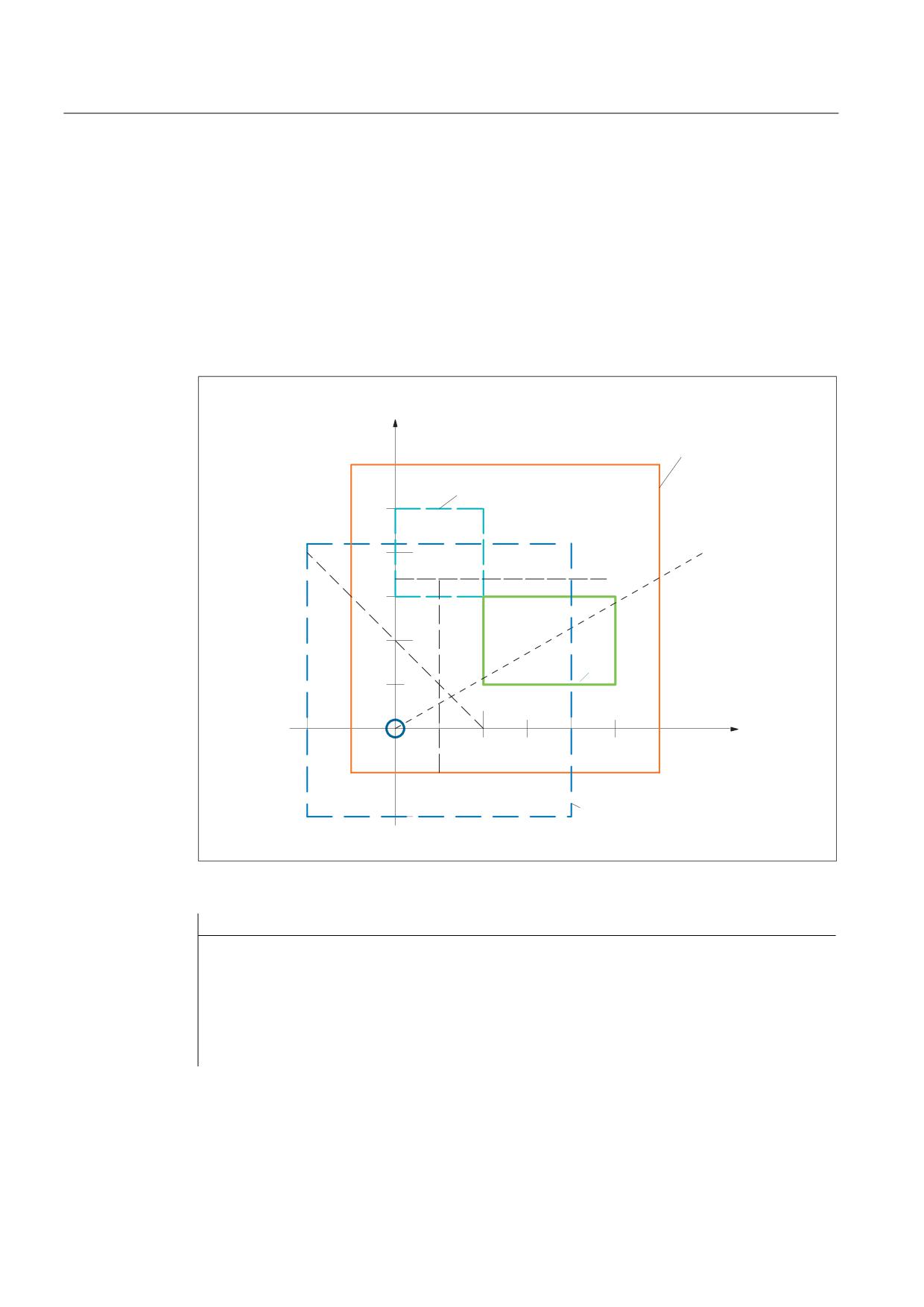
In the example (refer to the diagram), X software limits and working area limits are shown. In
addition, three protection zones are defined, the two channel-specific protection zones C2
and C4 and well as the NCK protection zone N3. C2 is a circular, active, tool-related
protection zone with a radius of 2 mm. C4 is a square, pre-activated and workpiece-related
protection zone with 10 mm side length and N3 is a rectangular, active protection zone with
10 mm and 15 mm side lengths. In the following NC, initially, the protection zones and the
working field limits are defined as sketched, and the CALCPOSI function is called with
various parameter assignments. The results of each individual CALCPOSI call are
summarized in the table at the end of the example.
<
6RIWZDUH OLPLWV
&
SURDFWLYH
1
1
1
1
1
;
&
:RUNLQJ DUHD OLPLWDWLRQ
Program code
Comments
N10 def real _STARTPOS[3]
N20 def real _MOVDIST[3]
N30 def real _DLIMIT[5]
N40 def real _MAXDIST[3]
N50 def int _SB
N60 def int _STATUS
Job Planning
226
Programming Manual, 03/2010, 6FC5398-2BP20-1BA0
Protection zones
3.3 Checking for protection zone violation, working area limitation and software limits (CALCPOSI)
Program code
Comments
N70 cprotdef(2, true, 0)
;
Tool-related protection zone
N80 g17 g1 x-y0
N90 g3 i2 x2
N100
i-x-
N110
execute(_SB)
N120
cprotdef(4, false,
0)
;
Workpiece-related protection zone
N130
g17 g1 x0 y15
N140
x10
N150
y25
N160
x0
N170
y15
N180
execute(_SB)
N190
nprotdef(3, false,
0)
;
Machine-related protection zone
N200
g17 g1 x10 y5
N210
x25
N220
y15
N230
x10
N240
y5
N250
execute(_SB)
N260
cprot(2,2,0, 0, 0)
;
Activate or pre-activate
protection zones
N270
cprot(4,1,0, 0, 0)
N280
nprot(3,2,0, 0, 0)
N290
g25 XX=-YY=-
;
Define working area limit groups
N300
g26 xx= 20 yy= 21
N310
_STARTPOS[0] = 0.
N320
_STARTPOS[1] = 0.
N330
_STARTPOS[2] = 0.
N340
_MOVDIST[0] = 35.
N350
_MOVDIST[1] = 20.
N360
_MOVDIST[2] = 0.
N370
_DLIMIT[0] = 0.
N380
_DLIMIT[1] = 0.
N390
_DLIMIT[2] = 0.
N400
_DLIMIT[3] = 0.
N410
_DLIMIT[4] = 0.
;Various function calls
;
Other starting point
N420 _STATUS = calcposi(_STARTPOS,_MOVDIST,
_DLIMIT, _MAXDIST)
N430 _STATUS = calcposi(_STARTPOS,_MOVDIST,
_DLIMIT, _MAXDIST,,3)
N440 _STATUS = calcposi(_STARTPOS,_MOVDIST,
_DLIMIT, _MAXDIST,,1)
Job Planning
Programming Manual, 03/2010, 6FC5398-2BP20-1BA0
227
Protection zones
3.3 Checking for protection zone violation, working area limitation and software limits (CALCPOSI)
Program code
Comments
N450 _STARTPOS[0] = 5.
; Other destination
N460 _STARTPOS[1] = 17.
N470 _STARTPOS[2] = 0.
N480 _MOVDIST[0] = 0.
N490 _MOVDIST[1] =-.
N500 _MOVDIST[2] = 0.
;Various function calls
N510 _STATUS = calcposi(_STARTPOS,_MOVDIST,
_DLIMIT, _MAXDIST,,14)
N520 _STATUS = calcposi(_STARTPOS,_MOVDIST,
_DLIMIT, _MAXDIST,, 6)
N530 _DLIMIT[1] = 2.
N540 _STATUS = calcposi(_STARTPOS,_MOVDIST,
_DLIMIT, _MAXDIST,, 6)
N550 _STARTPOS[0] = 27.
N560 _STARTPOS[1] = 17.1
N570 _STARTPOS[2] = 0.
N580 _MOVDIST[0] =-.
N590 _MOVDIST[1] = 0.
N600 _MOVDIST[2] = 0.
N610 _DLIMIT[3] = 2.
N620 _STATUS = calcposi(_STARTPOS,_MOVDIST,
_DLIMIT, _MAXDIST,, 12)
N630 _STARTPOS[0] = 0.
N640 _STARTPOS[1] = 0.
N650 _STARTPOS[2] = 0.
N660 _MOVDIST[0] = 0.
N670 _MOVDIST[1] = 30.
N680 _MOVDIST[2] = 0.
N690 trans x10
N700 arot z45
N710 _STATUS = calcposi(_STARTPOS,_MOVDIST,
_DLIMIT, _MAXDIST)
N720 M30
Job Planning
228
Programming Manual, 03/2010, 6FC5398-2BP20-1BA0

Protection zones
3.3 Checking for protection zone violation, working area limitation and software limits (CALCPOSI)
Results of the tests in the example:
Block No.
_STATUS
_MAXDIST
_MAXDIST
Remarks
N...
[0] (= X)
[1] (= Y)
420
3123
8.040
4.594
Protection zone SB N3 violated.
430
1122
20.000
11.429
No protection zone monitoring, working
area limits violated.
440
1121
30.000
17.143
Now only monitoring of the software
limits active.
510
4213
0.000
0.000
Starting point violates protection C4
520
0000
0.000
-.000
Pre-activated protection zone C4 is not
monitored. Defined path can be
traversed completely.
540
2222
0.000
-.000
Because _DLIMIT[1]=2, the traversing
path is restricted by the working area
limits.
620
4223
-.000
0.000
Clearance to C4 is a total of 4 mm due
to C2 and _DLIMIT[3]. Clearance C2 -
N3 of 0.1 mm does not lead to limiting
the traversing path.
710
1221
0.000
21.213
Frame with translation and rotation
active The permissible traversing path in
_MOVDIST applies in the shifted and
rotated coordinate system (WCS).
Special cases and further details
All path data are always entered as radii even if for a facing axis with active G code
"DIAMON". If the part of one of the involved axes cannot be traversed completely, the paths
of the other axes will also be reduced accordingly in the _MAXDIST return value so that the
resulting end point lies on the specified path.
It is permissible that no software limits, operating range limits or protection zones are defined
for one or more of the axes involved. All limits are only monitored if the axes involved are
referenced. Any involved rotary axes are monitored only if they are not modulo axes.
As in the normal traversing operation, the monitoring of the software limits and the operating
range limits depends on the active settings (interface signals for selecting the software limits
1 or software limits 2, GWALIMON/WALIMOF, setting data for the specific activation of the
operating range limits and for the specification whether or not the radius of the active tool is
to be considered for the monitoring of the operating range limits).
Job Planning
Programming Manual, 03/2010, 6FC5398-2BP20-1BA0
229
Protection zones
3.3 Checking for protection zone violation, working area limitation and software limits (CALCPOSI)
For certain kinematic transformations (e.g. TRANSMIT), the position of the machine axes
cannot be determined uniquely from the positions in the workpiece coordinate system (WCS)
(non-uniqueness). In the normal traversing operation, the uniqueness normally results from
the previous history and the condition that a continuous movement in the WCS must
correspond to a continuous movement in the machine axes. When monitoring the software
limits using the CALCPOSI function, the current machine position is therefore used to
resolve non-unique determinability in such cases. If necessary, a STOPRE must be
programmed in front of CALCPOSI to input valid machine axis positions to the function.
It is not guaranteed that the separation to the protection zones specified in _DLIMIT[3] can
always be maintained for a movement on the specified traversal path. Therefore if the end
point returned in _MOVDIST is lengthened by this distance, no protection zone is violated,
even though the straight line may pass extremely close to a protection zone.
Note
You will find details on working area limitations in the
/PG/ Fundamentals Programming Manual,
on the software limits in
/FB1/ Function Manual, Basic Functions; Axis Monitoring, Protection Zones (A3).
Job Planning
230
Programming Manual, 03/2010, 6FC5398-2BP20-1BA0
Special Motion Commands
4
4.1
Approaching coded positions (CAC, CIC, CDC, CACP, CACN)
Function
You can traverse linear and rotary axes via position numbers to fixed axis positions saved in
machine data tables using the following commands. This type of programming is called
"approach coded positions".
Syntax
CAC(<n>)
CIC(<n>)
CACP(<n>)
CACN(<n>)
Significance
CAC(<n>)
Approach coded position from position number n
CIC(<n>)
Starting from the actual position number, approach the coded position n
position locations before (+n) or back (-n)
CDC(<n>)
Approach the position from position number n along the shortest path
(only for rotary axes)
CACP(<n>)
Approach coded position from position number n in the positive
direction (only for rotary axes)
CACN(<n>)
Approach coded position from position number n in the negative
direction (only for rotary axes)
<n>
Position number within the machine data table
Value range: 0, 1, … (max. number of table locations - 1)
Job Planning
Programming Manual, 03/2010, 6FC5398-2BP20-1BA0
231
Special Motion Commands
4.1 Approaching coded positions (CAC, CIC, CDC, CACP, CACN)
Example: Approach coded positions of a positioning axis
Programming code
Comments
N10 FA[B]=300
; Feedrate for positioning axis B
N20 POS[B]=CAC(10)
; Approach coded position from position number 10
N30 POS[B]=CIC(-4)
; Approach coded position from "current position
number" - 4
References
● Function Manual Expanded Functions; Indexing Axes (T1)
● Function Manual, Synchronized Actions
Job Planning
232
Programming Manual, 03/2010, 6FC5398-2BP20-1BA0
Special Motion Commands
4.2 Spline interpolation (ASPLINE, BSPLINE, CSPLINE, BAUTO, BNAT, BTAN, EAUTO, ENAT, ETAN, PW, SD, PL)
4.2
Spline interpolation (ASPLINE, BSPLINE, CSPLINE, BAUTO,
BNAT, BTAN, EAUTO, ENAT, ETAN, PW, SD, PL)
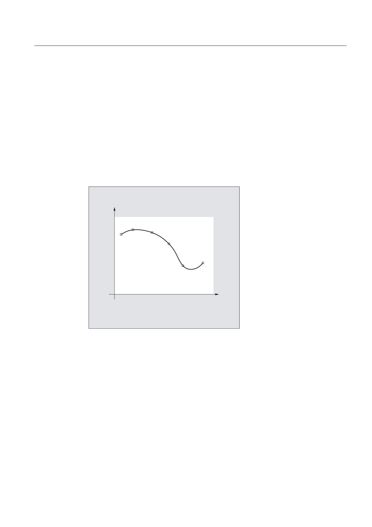
Function
Random curved workpiece contours cannot be precisely defined in an analytic form. This is
the reason that these type of contours are approximated using a limit number of points along
curves, e.g. when digitizing surfaces. The points along the curve must be connected to
define a contour in order to generate the digitized surface of a workpiece. Spline
interpolation permits this.
A spline defines a curve, which is formed from polynomials of 2nd or 3rd degree. The
characteristics of the points along the curve of a spline can be defined depending on the
spline type being used.
3
3
3
3
3
3
3
WR 3
VSHFLILHG FRRUGLQDWHV
For SINUMERIK solution line, the following spline types are available:
● A spline
● B spline
● C spline
Job Planning
Programming Manual, 03/2010, 6FC5398-2BP20-1BA0
233
Special Motion Commands
4.2 Spline interpolation (ASPLINE, BSPLINE, CSPLINE, BAUTO, BNAT, BTAN, EAUTO, ENAT, ETAN, PW,
SD, PL)
Syntax
General:
ASPLINE X... Y... Z... A... B... C...
BSPLINE X... Y... Z... A... B... C...
CSPLINE X... Y... Z... A... B... C...
For a B spline, the following can be additionally programmed:
PW=<n>
SD=2
PL=<value>
For A and C splines, the following can be additionally programmed:
BAUTO / BNAT / BTAN
EAUTO / ENAT / ETAN
Significance
Spline interpolation type:
ASPLINE
Command to activate A spline interpolation
BSPLINE
Command to activate B spline interpolation
CSPLINE
Command to activate C spline interpolation
The ASPLINE, BSPLINE and CSPLINE commands are modally effective
and belong to the group of motion commands.
Points along a curve and check points:
X... Y... Z...
A... B... C...
Positions in Cartesian coordinates
Point weight (only B spline):
PW
Using the PW command, a so-called "point weight" can be
programmed for every point along the curve.
<n>
"Point weight"
Range of values:
0 ≤ n ≤ 3
Increment:
0.0001
Effect:
n > 1
The checkpoint attracts the curve
more significantly.
n < 1
The checkpoint attracts the curve
less significantly.
Spline degree (only B spline):
SD
A third degree polygon is used as standard, However, a second
degree polygon can also be used by programming SD=2.
Job Planning
234
Programming Manual, 03/2010, 6FC5398-2BP20-1BA0
Special Motion Commands
4.2 Spline interpolation (ASPLINE, BSPLINE, CSPLINE, BAUTO, BNAT, BTAN, EAUTO, ENAT, ETAN, PW, SD, PL)
Distance between nodes (only B spline):
PL
The distances between nodes are suitably calculated internally.
The control can also machine pre-defined node clearances that
are specified in the so-called parameter-interval-length using the
PL command.
<value>
Parameter interval length
Range of values: As for path dimension
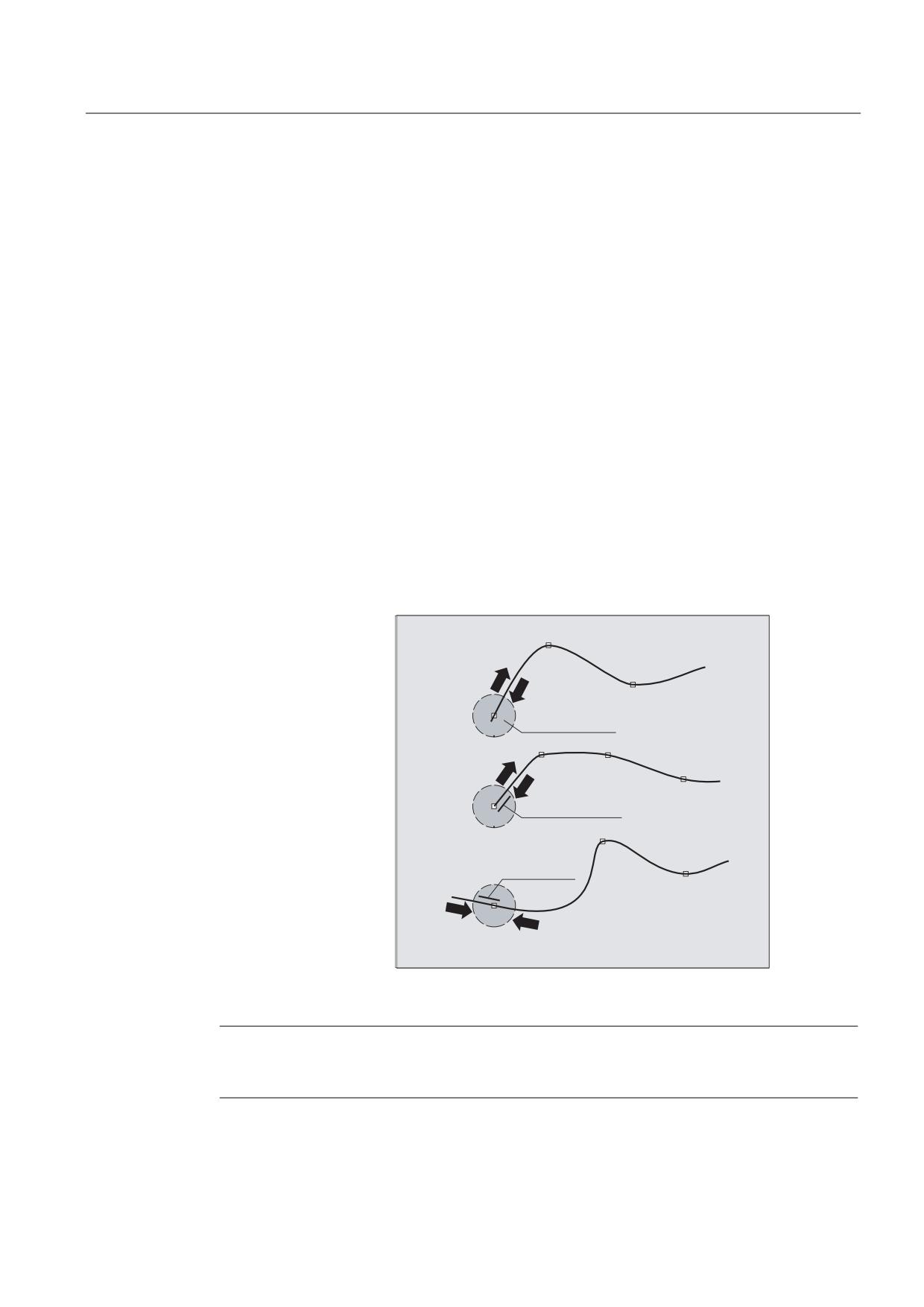
Transitional behavior at the start of the spline curve (only A or C spline):
BAUTO
No specifications for the transitional behavior. The start is
determined by the position of the first point.
BNAT
Zero curvature
BTAN
Tangential transition to the previous block (delete position)
Transitional behavior at the end of the spline curve (only A or C spline):
EAUTO
No specifications for the transitional behavior. The end is
determined by the position of the last point.
ENAT
Zero curvature
ETAN
Tangential transition to the previous block (delete position)
%$872
($872
1R LQSXW
%1$7
(1$7
=HUR FXUYDWXUH
7DQJHQWLDO
WUDQVLWLRQ
%7$1
(7$1
Note
The programmable transitional behavior has no influence on the B spline. The B spline is
always tangential to the check polygon at its start and end points.
Job Planning
Programming Manual, 03/2010, 6FC5398-2BP20-1BA0
235
Special Motion Commands
4.2 Spline interpolation (ASPLINE, BSPLINE, CSPLINE, BAUTO, BNAT, BTAN, EAUTO, ENAT, ETAN, PW,
SD, PL)
Supplementary conditions
● Tool radius compensation may be used.
● Collision monitoring is carried out in the projection in the plane.
Examples
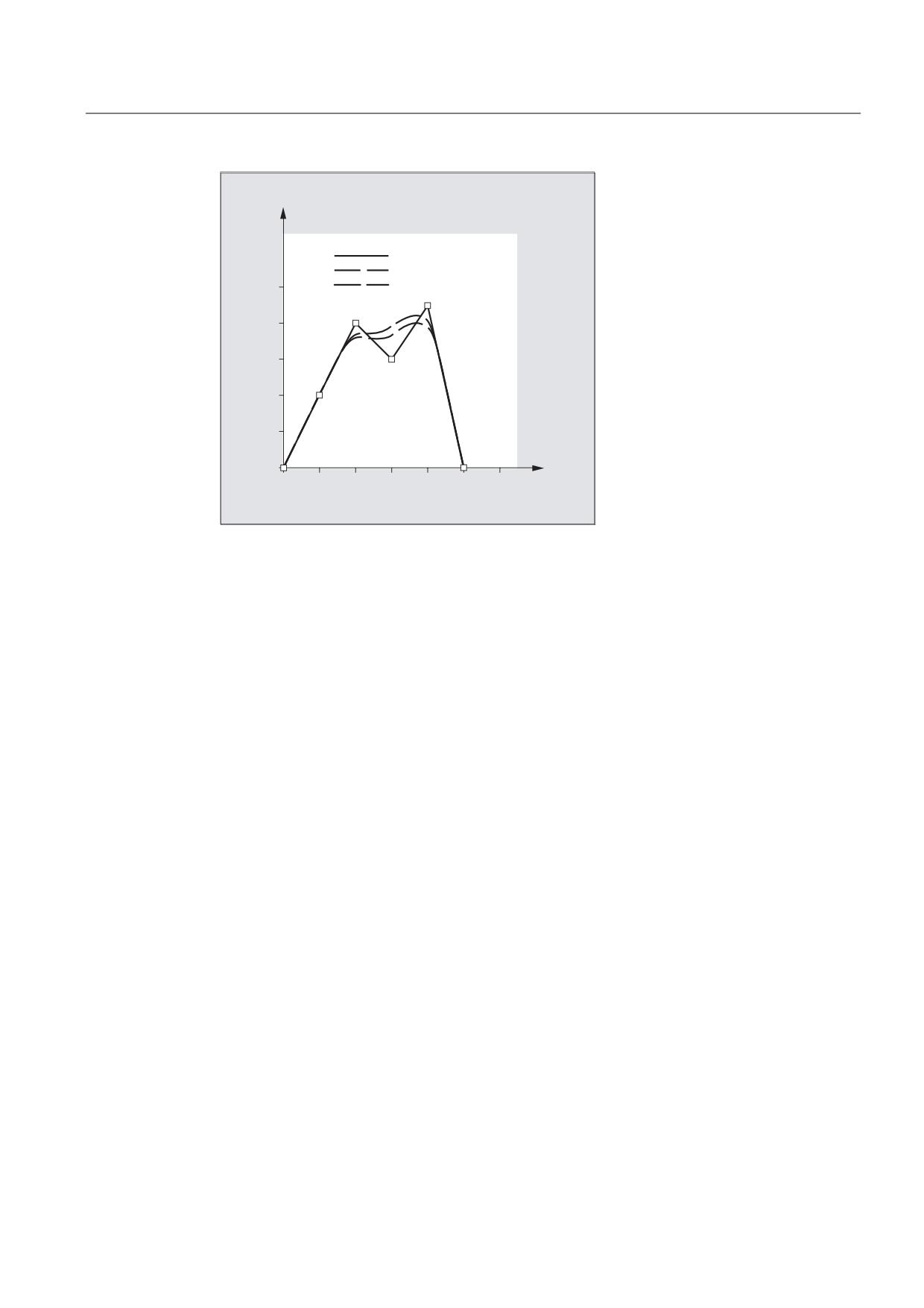
Example 1: B spline
Program code 1 (all weights 1)
N10 G1 X0 Y0 F300 G64
N20 BSPLINE
N30 X10 Y20
N40 X20 Y40
N50 X30 Y30
N60 X40 Y45
N70 X50 Y0
Program code 2 (different weights)
N10 G1 X0 Y0 F300 G64
N20 BSPLINE
N30 X10 Y20 PW=2
N40 X20 Y40
N50 X30 Y30 PW=0.5
N60 X40 Y45
N70 X50 Y0
Program code 3 (check polygon)
Comments
N10 G1 X0 Y0 F300 G64
N20
; N/A
N30 X10 Y20
N40 X20 Y40
N50 X30 Y30
N60 X40 Y45
N70 X50 Y0
Job Planning
236
Programming Manual, 03/2010, 6FC5398-2BP20-1BA0
Special Motion Commands
4.2 Spline interpolation (ASPLINE, BSPLINE, CSPLINE, BAUTO, BNAT, BTAN, EAUTO, ENAT, ETAN, PW, SD, PL)
<
&KHFN SRO\JRQ
$OO ZHLJKWV
'LIIHUHQW ZHLJKWV
;
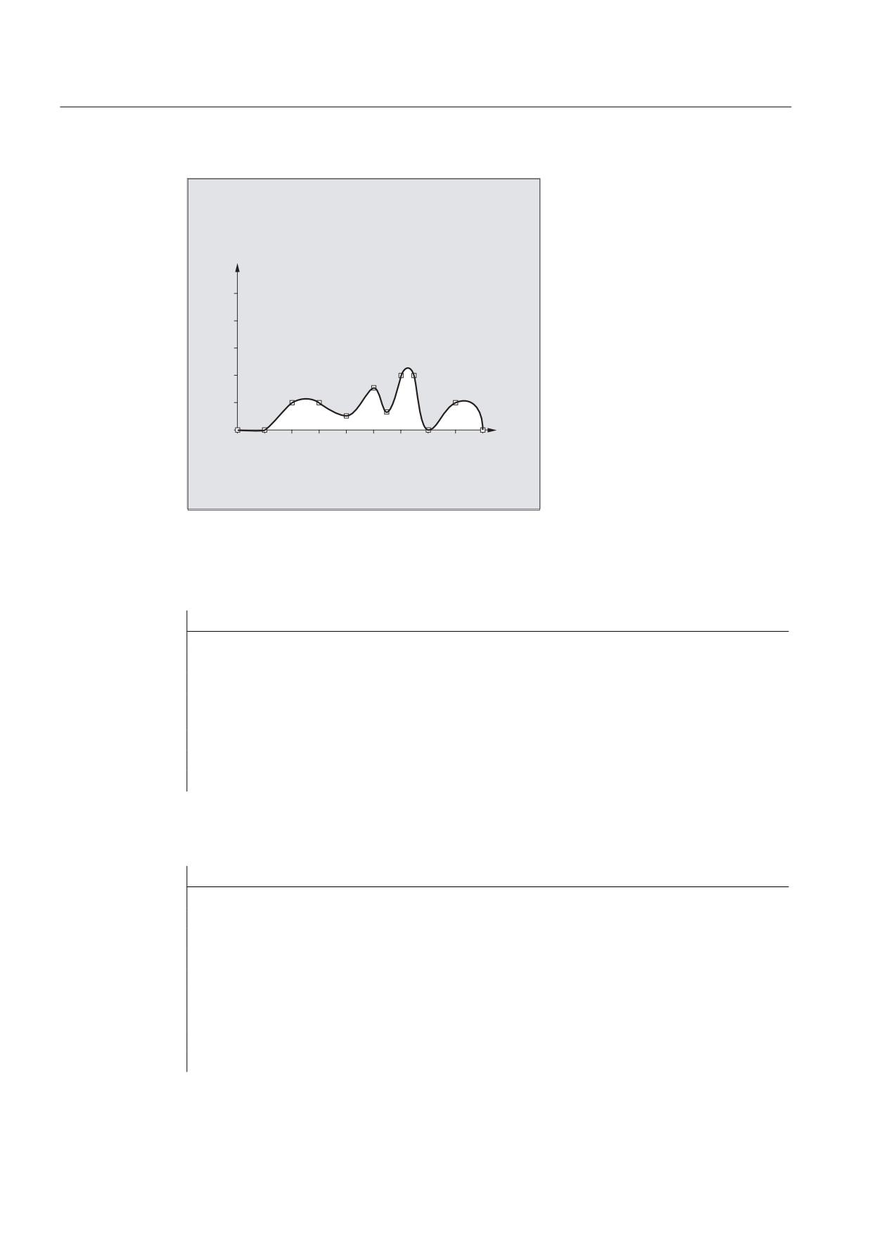
Example 2: C spline, zero curvature at the start and at the end
Program code
N10 G1 X0 Y0 F300
N15 X10
N20 BNAT ENAT
N30 CSPLINE X20 Y10
N40 X30
N50 X40 Y5
N60 X50 Y15
N70 X55 Y7
N80 X60 Y20
N90 X65 Y20
N100 X70 Y0
N110 X80 Y10
N120 X90 Y0
N130 M30
Job Planning
Programming Manual, 03/2010, 6FC5398-2BP20-1BA0
237
Special Motion Commands
4.2 Spline interpolation (ASPLINE, BSPLINE, CSPLINE, BAUTO, BNAT, BTAN, EAUTO, ENAT, ETAN, PW,
SD, PL)
<
;
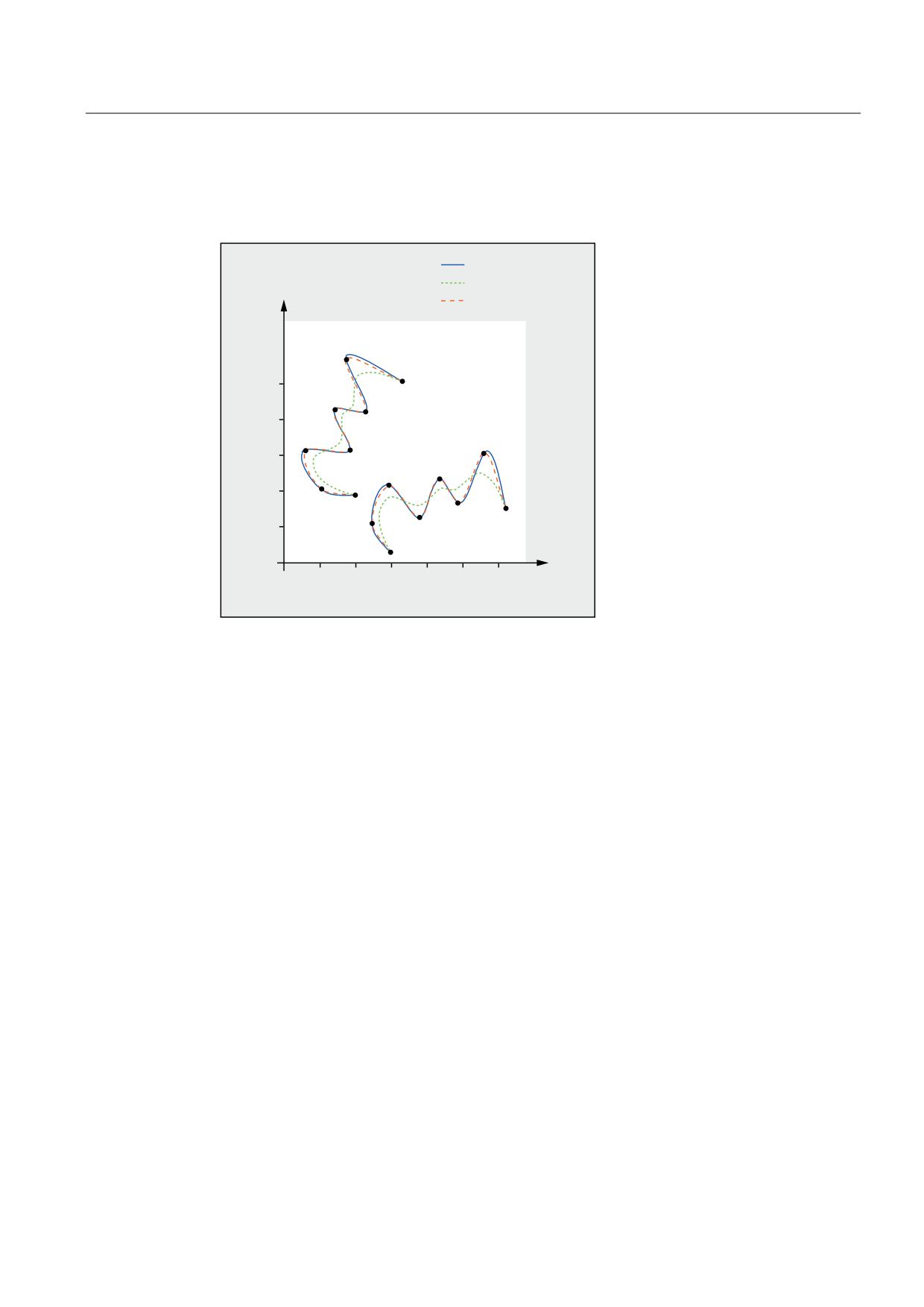
Example 3: Spline interpolation (A spline) and coordinate transformation (ROT)
Main program:
Program code
Comments
N10 G00 X20 Y18 F300 G64
; Approach starting point
N20 ASPLINE
; Activate interpolation type A spline.
N30 CONTOUR
; First subprogram call.
N40 ROT Z-45
; Coordinate transformation: Rotation of the
WCS through -45° around the Z axis.
N50 G00 X20 Y18
; Approach contour starting point.
N60 CONTOUR
; Second subprogram call.
N70 M30
; End of program
Subprogram "contour" (includes the coordinates of the points along the curve):
Program code
N10 X20 Y18
N20 X10 Y21
N30 X6 Y31
N40 X18 Y31
N50 X13 Y43
N60 X22 Y42
N70 X16 Y58
N80 X33 Y51
N90 M1
Job Planning
238
Programming Manual, 03/2010, 6FC5398-2BP20-1BA0
Special Motion Commands
4.2 Spline interpolation (ASPLINE, BSPLINE, CSPLINE, BAUTO, BNAT, BTAN, EAUTO, ENAT, ETAN, PW, SD, PL)
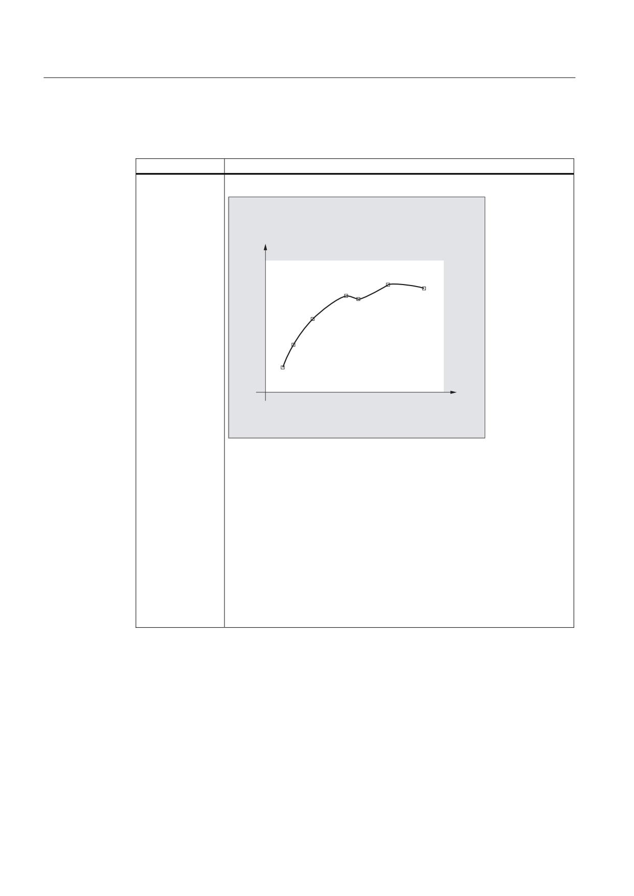
In addition to the spline curve, resulting from the example program (ASPLINE), the following
diagram also contains the spline curves that would have been obtained when activating
either B or C spline interpolation (BSPLINE, CSPLINE):
$63/,1(
%63/,1(
<
&63/,1(
1
)LUVW VXESURJUDP FDOO
1
6HFRQG VXE
SURJUDP FDOO
;
Further Information
Advantages of spline interpolation
By using spline interpolation, the following advantages can be obtained contrary to using
straight line blocks G01:
● The number of part program blocks required to describe the contour are reduced
● Soft, curve characteristics that reduce the stress on the mechanical system at transitions
between part program blocks.
Job Planning
Programming Manual, 03/2010, 6FC5398-2BP20-1BA0
239
Special Motion Commands
4.2 Spline interpolation (ASPLINE, BSPLINE, CSPLINE, BAUTO, BNAT, BTAN, EAUTO, ENAT, ETAN, PW,
SD, PL)
Properties and use of the various spline types
Spline type
Properties and use
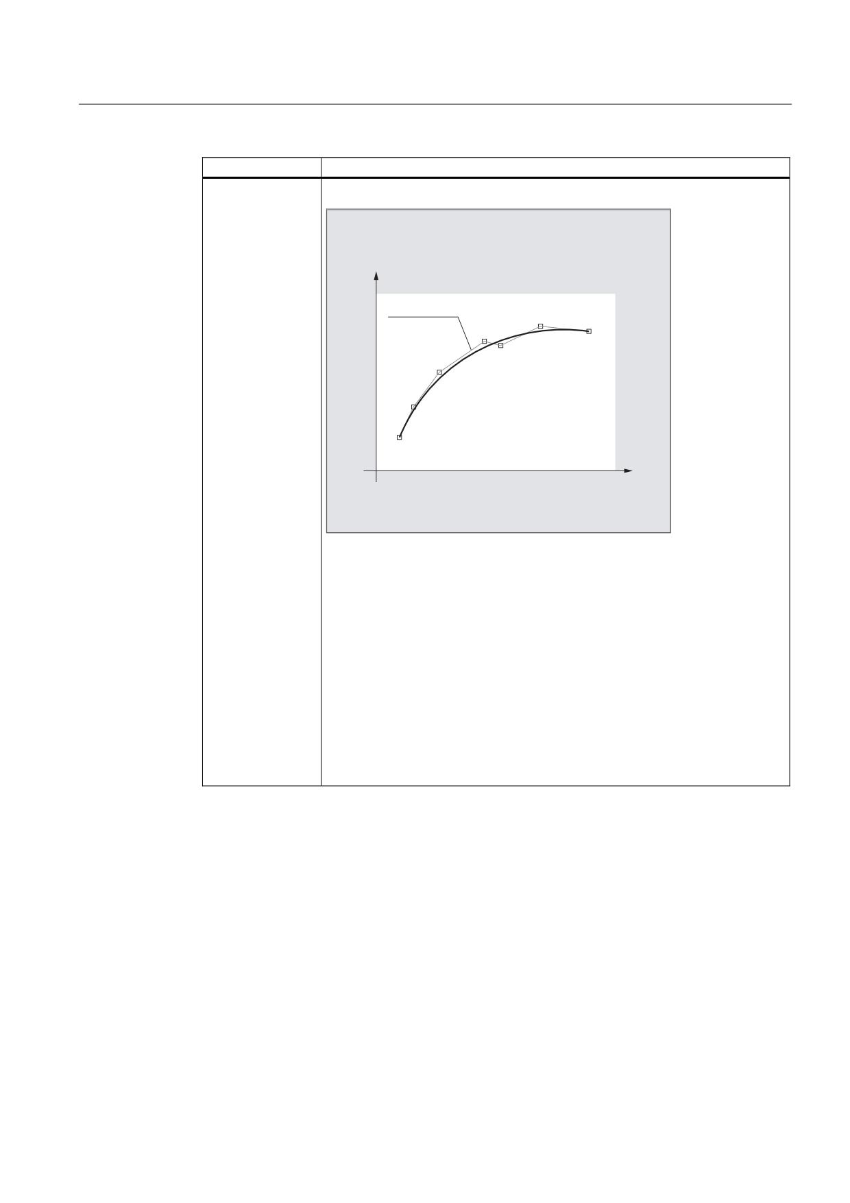
A spline
$ VSOLQH DNLPD VSOLQH
3
3
3
3
3
3
3
3
WR 3
VSHFLILHG FRRUGLQDWHV
Properties:
• The passes precisely through the specified intermediate points along the
curve.
• The curve characteristic is tangential, but does not have continuous
curvature.
• Produces hardly any undesirable oscillations.
• The area of influence of changes to intermediate points along the curve is
local. This means that a change to an intermediate point along the curve only
affects up to max. 6 adjacent intermediate points.
Application:
The A spline is especially suitable for interpolating curves with large changes in
the gradient (e.g. staircase-type curves and characteristics).
Job Planning
240
Programming Manual, 03/2010, 6FC5398-2BP20-1BA0
Special Motion Commands
4.2 Spline interpolation (ASPLINE, BSPLINE, CSPLINE, BAUTO, BNAT, BTAN, EAUTO, ENAT, ETAN, PW, SD, PL)
Spline type
Properties and use
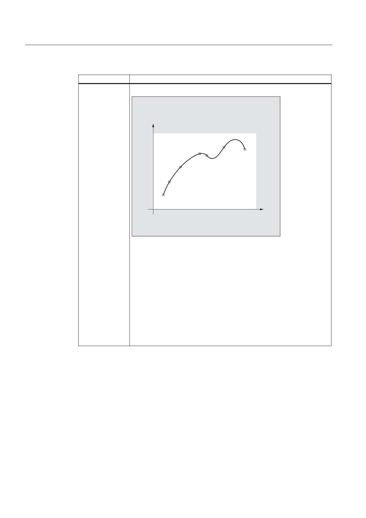
B spline
% VSOLQH
&KHFN SRO\JRQ
3
3
3
3
3
3
3
3
WR 3
VSHFLILHG FRRUGLQDWHV
Features:
• Does not run through the specified intermediate points along the curve, but
only close to them. The intermediate points to not attract the curve. The
curve characteristic can be additionally influenced by weighting the
intermediate points using a factor.
• The curve characteristic is tangential with continuous curvature.
• Does not generate any undesirable oscillations.
• The area of influence of changes to intermediate points along the curve is
local. This means that a change to an intermediate point along the curve only
affects up to max. 6 adjacent intermediate points.
Application:
Their B spline is primarily intended as interface to CAD systems.
Job Planning
Programming Manual, 03/2010, 6FC5398-2BP20-1BA0
241
Special Motion Commands
4.2 Spline interpolation (ASPLINE, BSPLINE, CSPLINE, BAUTO, BNAT, BTAN, EAUTO, ENAT, ETAN, PW,
SD, PL)
Spline type
Properties and use
C spline
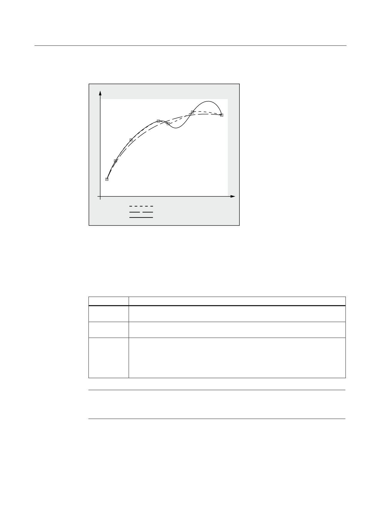
& VSOLQH FXELF VSOLQH
3
3
3
3
3
3
3
3
WR 3
VSHFLILHG FRRUGLQDWHV
Features:
• The passes precisely through the specified intermediate points along the
curve.
• The curve characteristic is tangential with continuous curvature.
• Frequently generates undesirable oscillations, especially at positions where
the gradient changes significantly.
• The area of influence of changes to the intermediate points is global. This
means that if an intermediate point is changed then this influences the
complete curved characteristic.
Application:
The C spline can be well used if the intermediate points lie on a curve that can
be analytically calculated defined (circle, parabola, hyperbola).
Job Planning
242
Programming Manual, 03/2010, 6FC5398-2BP20-1BA0
Special Motion Commands
4.2 Spline interpolation (ASPLINE, BSPLINE, CSPLINE, BAUTO, BNAT, BTAN, EAUTO, ENAT, ETAN, PW, SD, PL)
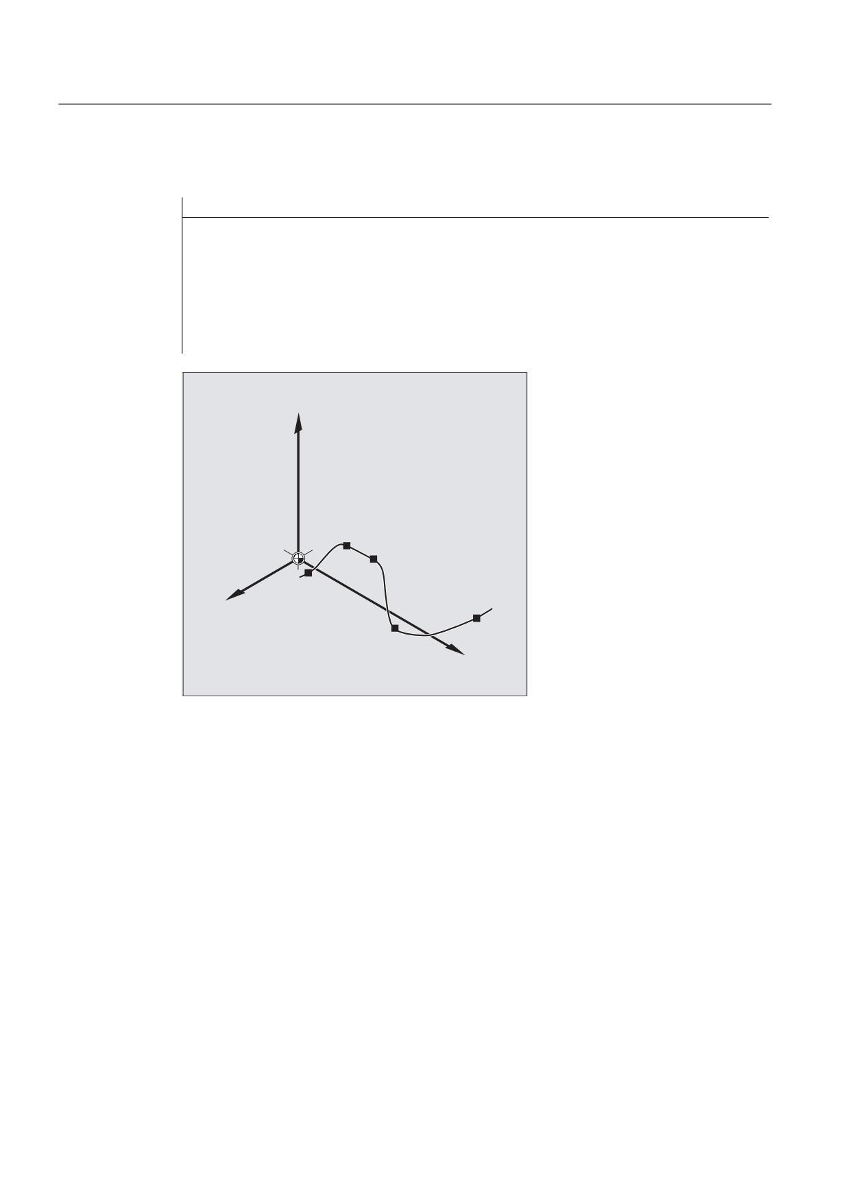
Comparison of three spline types with identical interpolation points
3
3
3
3
3
3
3
$ VSOLQH
% VSOLQH
& VSOLQH
Minimum number of spline blocks
The G codes ASPLINE, BSPLINE and CSPLINE link block end points with splines. For this
purpose, a series of blocks (end points) must be simultaneously calculated. The buffer size
for calculations is ten blocks as standard. Not every piece of block information is a spline end
point. However, the controller needs a certain number of spline end-point blocks for every 10
blocks:
Spline type
Minimum number of spline blocks
A spline:
At least 4 blocks out of every 10 must be spline blocks.
These do not include comment blocks or parameter calculations.
B spline:
At least 6 blocks out of every 10 must be spline blocks.
These do not include comment blocks or parameter calculations.
C spline:
The required minimum number of spline blocks is the result of the following sum:
Value of MD20160 $MC_CUBIC_SPLINE_BLOCKS + 1
The number of points used to calculate the spline segment is entered in MD20160.
The default setting is 8. As standard, at least 9 blocks out of every 10 must be spline
blocks.
Note
An alarm is output if the tolerated value is undershot and likewise when one of the axes
involved in the spline is programmed as a positioning axis.
Job Planning
Programming Manual, 03/2010, 6FC5398-2BP20-1BA0
243
Special Motion Commands
4.2 Spline interpolation (ASPLINE, BSPLINE, CSPLINE, BAUTO, BNAT, BTAN, EAUTO, ENAT, ETAN, PW,
SD, PL)
Combine short spline blocks
Spline interpolation can result in short spline blocks, which reduce the path velocity
unnecessarily. The "Combine short spline blocks" function allows you to combine these
blocks such that the resulting block length is sufficient and does not reduce the path velocity.
The function is activated via the channel-specific machine data:
MD20488 $MC_SPLINE_MODE (setting for spline interpolation).
References:
Function Manual, Basic Functions; Continuous-Path Mode, Exact Stop, Look Ahead (B1),
Chapter: Combine short spline blocks
Job Planning
244
Programming Manual, 03/2010, 6FC5398-2BP20-1BA0
Special Motion Commands
4.3 Spline grouping (SPLINEPATH)
4.3
Spline grouping (SPLINEPATH)
Function
The axes to be interpolated in the spline group are selected using the SPLINEPATH command.
Up to eight path axes can be involved in a spline interpolation grouping.
Note
If SPLINEPATH is not explicitly programmed, then the first three axes of the channel are
traversed as spline group.
Syntax
The spline group is defined in a separate block:
SPLINEPATH(n,X,Y,Z,…)
Significance
SPLINEPATH
Command to define a spline group
n
=1 (fixed value)
X,Y,Z,…
Identifier of the path axes to be interpolated in the spline group
Job Planning
Programming Manual, 03/2010, 6FC5398-2BP20-1BA0
245
Special Motion Commands
4.3 Spline grouping (SPLINEPATH)
Example: Spline group with three path axes
Program code
Comments
N10 G1 X10 Y20 Z30 A40 B50 F350
N11 SPLINEPATH(1,X,Y,Z)
; Spline group
N13 CSPLINE BAUTO EAUTO X20 Y30 Z40 A50 B60
; C spline
N14 X30 Y40 Z50 A60 B70
; Intermediate points
…
N100 G1 X… Y…
; Deselect spline
interpolation
=
63/,1(3$7+
;<=
;
<
Job Planning
246
Programming Manual, 03/2010, 6FC5398-2BP20-1BA0
Special Motion Commands
4.4 NC block compression (COMPON, COMPCURV, COMPCAD, COMPOF)
4.4
NC block compression (COMPON, COMPCURV, COMPCAD,
COMPOF)
Function
CAD/CAM systems normally produce linear blocks, which meet the configured accuracy
specifications. In the case of complex contours, a large volume of data and short path
sections can result. The short path sections restrict the processing rate.
By using a compressor function, the contour, specified by using linear blocks, is approached
using polynomial blocks. This has the following advantages:
● Reduction of the number of required part program blocks for describing the workpiece
contour
● Continuous block transitions
● Higher maximum path velocities
The following compressor functions are available:
● COMPON
The block transitions are only constant in the velocity , while acceleration of the
participating axes can be in jumps at block transitions.
● COMPCURV
Block transitions have continuous acceleration. This ensures both smooth velocity and
acceleration of all axes at block transitions.
● COMPCAD
The compression that uses a lot of computation time and memory space is optimized
regarding surface quality and speed. COMPCAD should only be used if measures to
improve the surface cannot be taken by the CAD/CAM program in advance.
COMPOF terminates the compressor function.
Syntax
COMPON
COMPCURV
COMPCAD
COMPOF
Job Planning
Programming Manual, 03/2010, 6FC5398-2BP20-1BA0
247
Special Motion Commands
4.4 NC block compression (COMPON, COMPCURV, COMPCAD, COMPOF)
Meaning
COMPON:
Command to activate the compressor function COMPON.
Effective:
modal
COMPCURV:
Command to activate the compressor function COMPCURV.
Effective:
modal
COMPCAD:
Command to activate the compressor function COMPCAD.
Effective:
modal
COMPOF :
Command to deactivate the currently active compressor function.
Note
The rounding function G642 and jerk limitation SOFT can be used to achieve further
improvements in surface quality. These commands must be written at the beginning of the
program.
General conditions
● The NC block compression is generally executed for linear blocks (G1).
● Only blocks that comply with a simple syntax are compressed:
N... G1X... Y... Z... F... ;comment
All other blocks are executed unchanged (no compression).
● Motion blocks with extended addresses such as C=100 or A=AC(100) are also condensed.
● The position values do not have to be programmed directly, but can also be indirectly
specified using parameter assignments, e.g. X=R1*(R2+R3).
● If the option "orientation transformation" is available, then NC blocks in which the tool
orientation (and where relevant, also the tool rotation) is programmed using direction
vectors can also be compressed (see "Compressing the orientation (Page 353)").
● It is interrupted by any other type of NC instruction, e.g., an auxiliary function output.
Job Planning
248
Programming Manual, 03/2010, 6FC5398-2BP20-1BA0
Special Motion Commands
4.4 NC block compression (COMPON, COMPCURV, COMPCAD, COMPOF)
Examples
Example 1: COMPON
Program code
Comment
N10 COMPON
; Compressor function COMPON on.
N11 G1 X0.37 Y2.9 F600
; G1 before end point and feed.
N12 X16.87 Y-.698
N13 X16.865 Y-.72
N14 X16.91 Y-.799
…
N1037 COMPOF
; Compressor function off.
…
Example 2: COMPCAD
Program code
Comment
G00 X30 Y6 Z40
G1 F10000 G642
; Blending function G642 on.
SOFT
; Jerk limiting SOFT on.
COMPCAD
; Compressor function COMPCAD on.
STOPFIFO
N24050 Z32.499
N24051 X41.365 Z32.500
N24052 X43.115 Z32.497
N24053 X43.365 Z32.477
N24054 X43.556 Z32.449
N24055 X43.818 Z32.387
N24056 X44.076 Z32.300
…
COMPOF
; Compressor function off.
G00 Z50
M30
References
Function Manual, Basic Functions; Continuous-Path Mode, Exact Stop, Look Ahead (B1),
Chapter: "NC block compression"
Job Planning
Programming Manual, 03/2010, 6FC5398-2BP20-1BA0
249
Special Motion Commands
4.5 Polynomial interpolation (POLY, POLYPATH, PO, PL)
4.5
Polynomial interpolation (POLY, POLYPATH, PO, PL)
Function
It actually involves a polynomial interpolation (POLY) and not a spline interpolation type. Its
main purpose is to act as an interface for programming externally generated spline curves
where the spline sections can be programmed directly.
This mode of interpolation relieves the NC of the task of calculating polynomial coefficients. It
can be optimally applied in cases where the coefficients are supplied directly by a CAD
system or post processor.
Syntax
3rd degree polynomial:
POLY PO[X]=(xe,a2,a3) PO[Y]=(ye,b2,b3) PO[Z]=(ze,c2,c3) PL=n
5th degree polynomial and new polynomial syntax:
POLY X=PO(xe,a2,a3,a4,a5) Y=PO(ye,b2,b3,b4,b5) Z=PO(ze,c2,c3,c4,c5)
PL=n
POLYPATH("AXES","VECT")
Note
The sum of the polynomial coefficients and axes programmed in an NC block must not
exceed the maximum permitted number of axes per block.
Meaning
POLY :
Activation of polynomial interpolation with a
block containing POLY.
POLYPATH :
Polynomial interpolation can be selected for
both AXIS or VECT axis groups
PO[axis identifier/variable] :
End points and polynomial coefficients
X, Y, Z :
Axis identifier
xe, ye, ze :
Specification of end position for the particular
axis; value range as for path dimension
Job Planning
250
Programming Manual, 03/2010, 6FC5398-2BP20-1BA0
Special Motion Commands
4.5 Polynomial interpolation (POLY, POLYPATH, PO, PL)
a2, a3, a4, a5 :
The coefficients a2, a3, a4, and a5 are written
with their value; value range as for path
dimension. The last coefficient in each case
can be omitted if it equals zero.
PL :
Length of the parameter interval where
polynomials are defined (definition range of
the function f(p)).
The interval always starts at 0, p can assume
values from 0 to PL.
Theoretical value range for PL:
0.0001 … 99 999.9999
Note:
The PL value applies to the block in which it
is located. If no PL is programmed, then
PL=1 is applied.
Activating/deactivating polynomial interpolation
The polynomial interpolation is activated in the part program using the POLX G command.
The POLY G command together with G0, G1, G2, G3, ASPLINE, BSPLINE and CSPLINE belong to
the 1st group.
Axes, which are only programmed with name and end point (e.g. X10), are linearly moved. If
all axes of an NC block are programmed in this way, the control behaves the same as for
G1.
The polynomial interpolation is implicitly deactivated again by programming another
command of the 1st G group G0, G1).
Polynomial coefficient
The PO value (PO[]=) or ...=PO(...) specifies all polynomial coefficients for an axis.
Several values are specified, separated by commas corresponding the degree of the
polynomial. Different degrees of polynomials are possible for various axes within one block.
POLYPATH subprogram
Using POLYPATH(...), the polynomial interpolation can be selectively released for certain axis
groups:
POLYPATH("AXES")
Only path axes and supplementary axes:
POLYPATH("VECT")
Only orientation axes:
(when moving with orientation transformation)
The axes that are not released are linearly moved.
Polynomial interpolation is enabled as standard for both axis groups.
Polynomial interpolation is deactivated for all axes by programming without the POLYPATH( )
parameter.
Job Planning
Programming Manual, 03/2010, 6FC5398-2BP20-1BA0
251
Special Motion Commands
4.5 Polynomial interpolation (POLY, POLYPATH, PO, PL)
Example
Program code
Comment
N10 G1 X… Y… Z… F600
N11 POLY PO[X]=(1,2.5,0.7) PO[Y]=(0.3,1,3.2) PL=1.5
; Polynomial interpolation on
N12 PO[X]=(0,2.5,1.7) PO[Y]=(2.3,1.7) PL=3
N20 M8 H126 …
N25 X70 PO[Y]=(9.3,1,7.67) PL=5
; Mixed data for the axes
N27 PO[X]=(10,2.5) PO[Y]=(2.3)
; No PL programmed; PL=1 applies
N30 G1 X… Y… Z.
; Polynomial interpolation off
…
Example: New polynomial syntax
Polynomial syntax that is still valid
New polynomial syntax
PO[axis identifier]=(.. , ..)
Axis identifier=PO(.. , ..)
PO[PHI]=(.. , ..)
PHI=PO(.. , ..)
PO[PSI]=(.. , ..)
PSI=PO(.. , ..)
PO[THT]=(.. , ..)
THT=PO(.. , ..)
PO[]=(.. , ..)
PO(.. , ..)
PO[variable]=IC(.. , ..)
variable=PO IC(.. , ..)
Example: Curve in the X/Y plane
Programming
Program code
N9 X0 Y0 G90 F100
N10 POLY PO[Y]=(2) PO[X]=(4,0.25) PL=4
Job Planning
252
Programming Manual, 03/2010, 6FC5398-2BP20-1BA0
Special Motion Commands
4.5 Polynomial interpolation (POLY, POLYPATH, PO, PL)
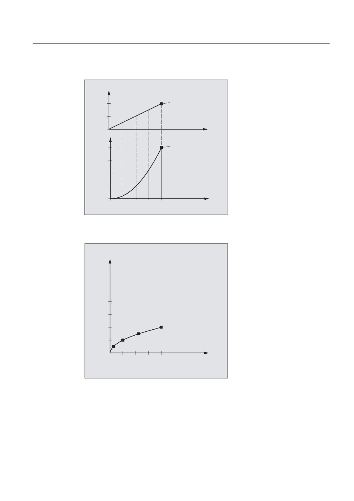
Shape of the curves X(p) and Y(p)
<
(QG SRLQW
S
;
(QG SRLQW
([DPSOH
1 ; < *
1
32/< 32><@
32>;@
3/
S
3/
Shape of the curve in the XY plane
<
5HVXOW LQ ;< SODQH
3/
;
Job Planning
Programming Manual, 03/2010, 6FC5398-2BP20-1BA0
253
Special Motion Commands
4.5 Polynomial interpolation (POLY, POLYPATH, PO, PL)
Description
The equation used to express the polynomial function is generally as follows:
f(p)= a0 + a1p + a2p2 +. . . + anpn
with: an: Constant coefficients
p: Parameter
In the control, polynomials up to a maximum of the 5th degree can be programmed:
f(p)= a0 + a1p + a2p2 + a3p3 + a4p4 + a5p5
By assigning concrete values to these coefficients, it is possible to generate various curve
shapes such as line, parabola and power functions.
A straight line is generated using a2 = a3 = a4 = a5 = 0:
f(p) = a0 + a1p
The following still applies:
a0: Axis position at the end of the preceding block
p = PL
a1 = (xE - a0 - a2*p2 - a3*p3)/p
It is possible to program polynomials without the polynomial interpolation having been
activated using the G command POLY. In this case, the programmed polynomials are not
interpolated, but instead, all of the programmed end points of the axis are linearly
approached (G1). The programmed polynomials are only moved as such as after explicitly
activating polynomial interpolation in the part program (POLY).
Special feature: Denominator polynomial
Command PO[]=(…) can be used to program a common denominator polynomial for the
geometry axes (without specifying an axis name), i.e., the motion of the geometry axes is
then interpolated as the quotient of two polynomials.
With this programming option, it is possible to represent forms such as conics (circle, ellipse,
parabola, hyperbola) exactly.
Example:
Program code
Comment
POLY G90 X10 Y0 F100
;
Geometry axes traverse linearly to
position X10 Y0.
PO[X]=(0,-10) PO[Y]=(10) PO[]=(2,1)
;
Geometry axes traverse along the
quadrant to X0 Y10.
The constant coefficient (a0) of the denominator polynomial is always assumed to be 1. The
programmed end point is independent of G90 / G91.
Job Planning
254
Programming Manual, 03/2010, 6FC5398-2BP20-1BA0
Special Motion Commands
4.5 Polynomial interpolation (POLY, POLYPATH, PO, PL)
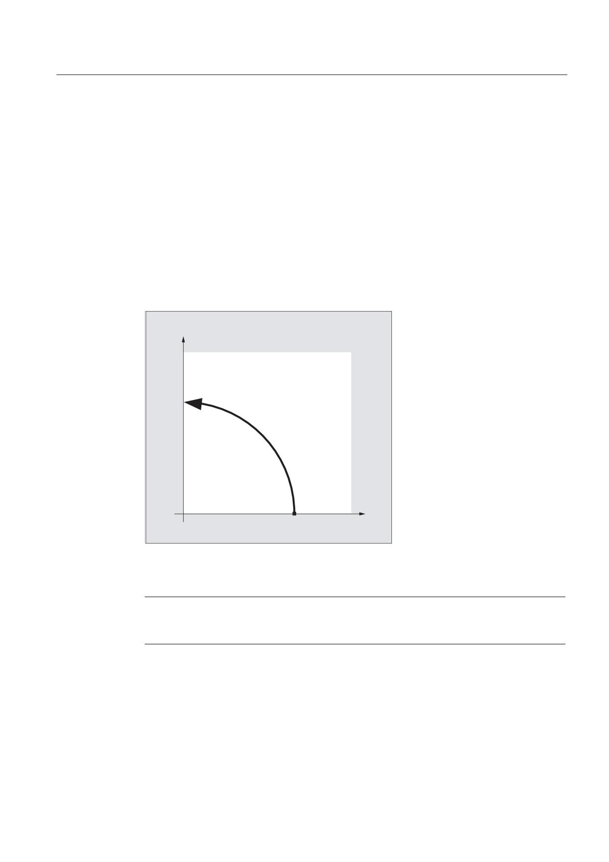
X(p) and Y(p) are calculated as follows from the programmed values:
X(p) = (10 - 10 * p2) / (1 + p2)
Y(p) = 20 * p / (1 + p2)
with 0 ≤ p ≤ 1
As a result of the programmed start points, end points, coefficient a2 and PL=1, the
intermediate results are as follows:
Numerator (X) =
10 + 0 * p - 10 * p2
Numerator (Y) =
0 + 20 * p + 0 * p2
Denominator =
1 + p2
<
;
If polynomial interpolation is active and a denominator polynomial is programmed with zeros
within the interval [0,PL], this is rejected and an alarm is output. Denominator polynomials
have no effect on the motion of special axes.
Note
Tool radius compensation can be activated with G41, G42 in conjunction with polynomial
interpolation and can be applied in the same way as in linear or circular interpolation modes.
Job Planning
Programming Manual, 03/2010, 6FC5398-2BP20-1BA0
255
Special Motion Commands
4.6 Settable path reference (SPATH, UPATH)
4.6
Settable path reference (SPATH, UPATH)
Function
During polynomial interpolation, the user may require two different relationships between the
velocity determining FGROUP axes and the other path axes: The latter should either be
controlled, synchronized to the path S or synchronized to the curve parameter U of the
FGROUP axes.
Both types of path interpolation are used in different applications and can be set/switched
over using the two modal language commands SPATH and UPATH contained in the 45th G code
group.
Syntax
SPATH
UPATH
Meaning
SPATH:
Path reference for FGROUP axes is arc length
UPATH:
Path reference for FGROUP axes is curve parameter
Note
UPATH and SPATH also define the interrelationship of the F word polynomial (FPOLY, FCUB, FLIN)
with path motion.
General conditions
The path reference set is of no importance:
● for linear and circular interpolation
● in thread blocks
● if all path axes are contained in FGROUP.
Job Planning
256
Programming Manual, 03/2010, 6FC5398-2BP20-1BA0
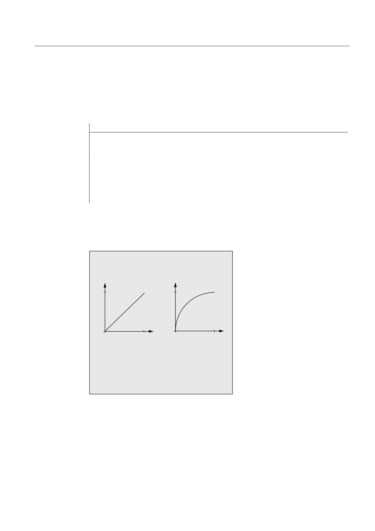
Special Motion Commands
4.6 Settable path reference (SPATH, UPATH)
Examples
Example 1:
The following example shows a square with 20 mm side lengths and corners rounded-off
with G643. The maximum deviations from the precise contour are defined for each axis
using the axis-specific machine data MD33100 $MA_COMPRESS_POS_TOL[<n>].
Program code
Comment
N10 G1 X… Y… Z… F500
N20 G643
; Block-internal corner rounding with G643
N30 XO Y0
N40 X20 Y0
; Edge length (mm) for the axes
N50 X20 Y20
N60 X0 Y20
N70 X0 Y0
N100 M30
Example 2:
The following example shows the difference between both types of motion control. Both
times the default setting FGROUP(X,Y,Z) is active.
63$7+
83$7+
$
$;
;
$
$;
6457 ;
;
;
'LIIHUHQW JHRPHWULFDO UHODWLRQVKLSV EHWZHHQ
D[HV IRU 63$7+ DQG 83$7+
Job Planning
Programming Manual, 03/2010, 6FC5398-2BP20-1BA0
257
Special Motion Commands
4.6 Settable path reference (SPATH, UPATH)
Program code
N10 G1 X0 A0 F1000 SPATH
N20 POLY PO[X]=(10,10) A10
or:
Program code
N10 G1 X0 F1000 UPATH
N20 POLY PO[X]=(10,10) A10
In block N20, path S of the FGROUP axes is dependent on the square of curve parameter U.
Therefore, different positions are obtained for the synchronous axis A along path X,
according to whether SPATH or UPATH is active.
Further information
During polynomial interpolation - and therefore this always involves polynomial interpolation
in a strict sense (POLY), all spline interpolation types (ASPLINE, BSPLINE, CSPLINE) and
linear interpolation with compressor function (COMPON, COMPCURV) - the positions of all
path axes i are specified by the polynomial pi(U). Curve parameter U moves from 0 to 1
within an NC block, therefore it is standardized.
The axes to which the programmed path feed is to relate can be selected from the path axes
by means of language command FGROUP. However, during polynomial interpolation, an
interpolation with constant velocity on path S of these axes usually means a non constant
change of curve parameter U.
Control behavior for reset and machine/option data
The G code, defined by MD20150 $MC_GCODE_RESET_VALUES[44] (45th G code group)
is effective after a reset. In order to maintain compatibility with existing installations, SPATH
is set as default value.
The initial state for the type of smoothing is defined with
MD20150 $MC_GCODE_RESET_VALUES[9] (10th G code group).
The axis-specific machine data MD33100 $MA_COMPRESS_POS_TOL[<n>] has an
extended significance: It contains the tolerances for the compressor function and for
smoothing with G642.
Job Planning
258
Programming Manual, 03/2010, 6FC5398-2BP20-1BA0
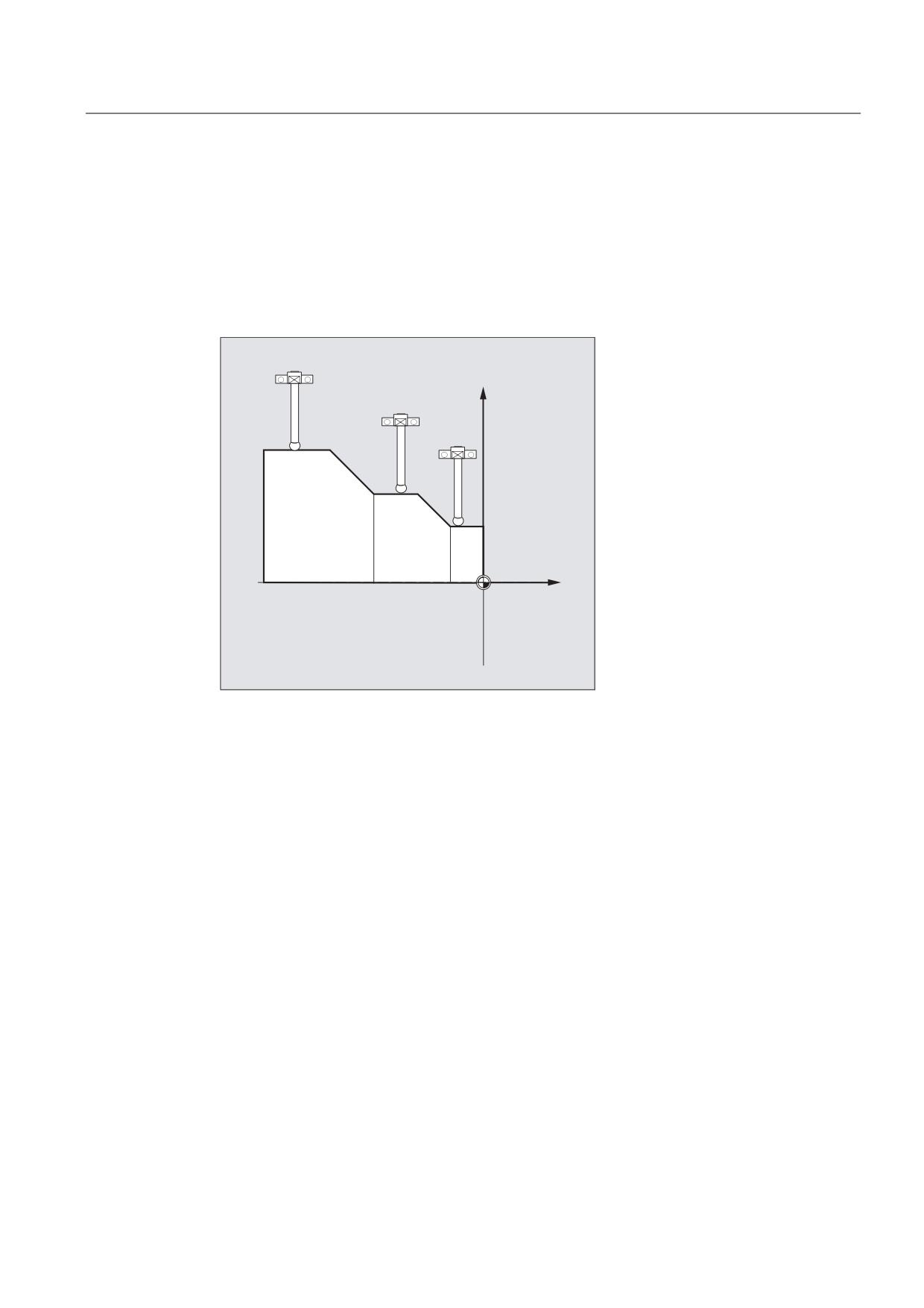
Special Motion Commands
4.7 Measurements with touch trigger probe (MEAS, MEAW)
4.7
Measurements with touch trigger probe (MEAS, MEAW)
Function
The "Measure with touch-trigger probe" is used to approach actual positions on the
workpiece. On the probe's switching edge, the positions for all axes programmed in the
measurement block are measured and written to the appropriate memory cell for each axis.
;
=
Programming measurement blocks
The following two commands are available for programming measurement blocks:
● MEAS
The MEAS command is used to delete the distance-to-go between the actual and setpoint
positions.
● MEAW
The MEAW command is used in the case of measuring tasks where the programmed
position always needs to be approached.
MEAS and MEAW are non-modal; they are programmed together with motion operations. The
feedrates and interpolation types (G0, G1, etc.), as well as the number of axes, must be
selected as appropriate for the measuring task at hand.
Job Planning
Programming Manual, 03/2010, 6FC5398-2BP20-1BA0
259
Special Motion Commands
4.7 Measurements with touch trigger probe (MEAS, MEAW)
Reading measurement results
The measurement results for the axes acquired with probes are available in the following
variables:
● $AA_MM[<axis>]
Measurement results in the machine coordinate system
● $AA_MW[<axis>]
Measurement results in the workpiece coordinate system
No internal preprocessing stop is generated when these variables are read.
Note
A preprocessing stop must be programmed with STOPRE at the appropriate position in the
program. The system will otherwise read false values.
Syntax
MEAS=<TE> G... X... Y... Z...
MEAW=<TE> G... X... Y... Z...
Significance
MEAS
Command: Measuring with deletion of distance-to-go
Effective:
non-modal
MEAW
Command: Measuring without deletion of distance-to-go
Effective:
non-modal
<TE>
Trigger event to initiate measurement
Type: INT
Range of
-2, -1, 1, 2
values:
Note:
There are up to a maximum of 2 probes (dependent
on configuration level).
Significance:
(+)1
Rising edge of probe 1 (measuring input 1)
-1
Falling edge of probe 1 (measuring input 1)
(+)2
Rising edge of probe 2 (measuring input 2)
-2
Falling edge of probe 2 (measuring input 2)
Note:
There are up to a maximum of 2 probes (dependent on configuration
level).
G...
Type of interpolation, e.g. G0, G1, G2 or G3
X... Y... Z...
End point in Cartesian coordinates
Job Planning
260
Programming Manual, 03/2010, 6FC5398-2BP20-1BA0

Special Motion Commands
4.7 Measurements with touch trigger probe (MEAS, MEAW)
Example
Program code
Comment
N10 MEAS=1 G1 F1000 X100 Y730 Z40
; Measurement block with probe at first
measuring input and linear
interpolation. A preprocessing stop is
automatically generated.
Further Information
Measuring job status
If an evaluation of whether or not the probe has been triggered is required in the program,
status variable $AC_MEA[n] (n= number of the measuring probe) can be checked:
Value
Significance
0
Measuring task not completed.
1
Measuring task completed successfully (the probe has been triggered).
Note
If the program is deflected in the program, the variable is set to 1. At the start of a
measurement block, the variable is automatically set to the initial state of the probe.
Reading measured values
The positions of all traversing path and positioning axes of the block are acquired (maximum
number of axes depending on the control configuration). In the case of MEAS, the motion is
decelerated in a defined fashion following the triggering of the probe.
Note
If a GEO axis is programmed in a measurement block, the measured values are stored for
all current GEO axes.
If an axis participating in a transformation is programmed in a measurement block, the
measured values for all axes participating in this transformation are recorded.
Job Planning
Programming Manual, 03/2010, 6FC5398-2BP20-1BA0
261
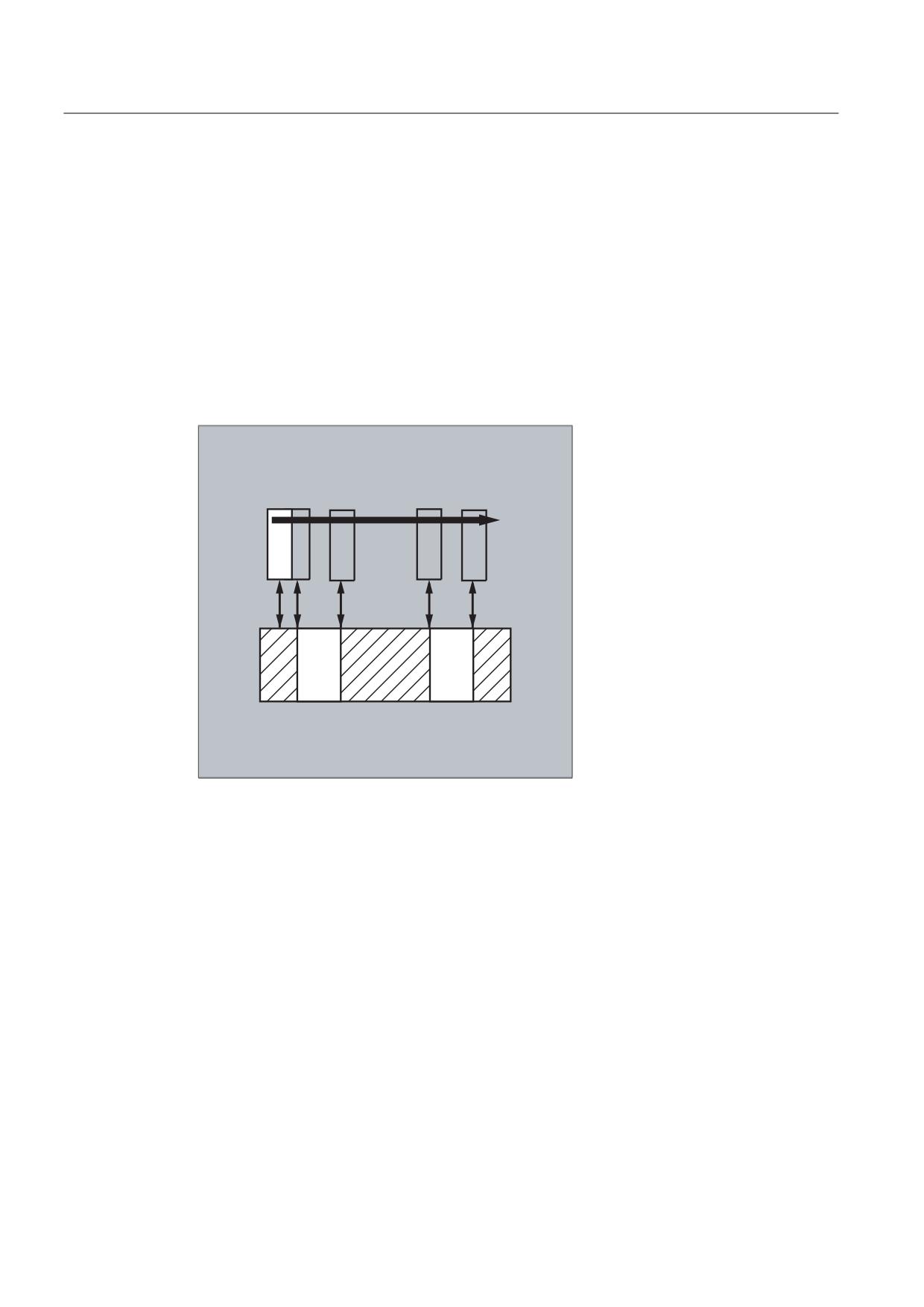
Special Motion Commands
4.8 Extended measuring function (MEASA, MEAWA, MEAC) (option)
4.8
Extended measuring function (MEASA, MEAWA, MEAC) (option)
Function
Several probes and several measuring systems can be used for the axial measuring.
The MEASA or MEAWA command can be used to acquire up to four measures values for the
respective programmed axis; these are then saved in system variables in accordance with
the trigger event.
Continuous measuring tasks can be executed with the MEAC command. In this case, the
measurement results are stored in FIFO variables. The maximum number of measured
values per measurement is also four with MEAC.
Reading measurement results
Measurement results are available in the following variables:
● $AA_MM1...4[<axis>]
Measurement results in the machine coordinate system
● $AA_MW1...4[<axis>]
Measurement results in the workpiece coordinate system
Syntax
MEASA[<axis>]=(<mode>,<TE1>,...,<TE4>)
MEAWA[<axis>]=(<mode>,<TE1>,...,<TE4>)
MEAC[<axis>]=(<mode>,<measurement memory>,<TE1>,...,<TE4>)
Job Planning
262
Programming Manual, 03/2010, 6FC5398-2BP20-1BA0
Special Motion Commands
4.8 Extended measuring function (MEASA, MEAWA, MEAC) (option)
Note
MEASA and MEAWA are non-modal; they can be programmed together in one block. However, if
MEASA/MEAWA is programmed together with MEAS/MEAW in the same block, an error message is
output.
Significance
MEASA
Command: Axial measurement with deletion of distance-to-go
Effective:
non-modal
MEAWA
Command: Axial measurement without deletion of distance-to-go
Effective:
non-modal
MEAC
Command: Continuous axial measurement without deletion of
distance-to-go
Effective:
non-modal
<axis>
Name of channel axis used for measurement
<mode>
Two-digit number indicating the operating mode (measuring mode
and measuring system)
Measuring mode (units decade):
0
Cancel measuring task.
1
Up to 4 different trigger events can be activated
simultaneously.
2
Up to 4 trigger events can be activated consecutively.
3
Up to 4 trigger events can be activated consecutively, but
with no monitoring of trigger event 1 on START (alarms
21700/21703 are suppressed).
Note:
This mode is not supported by MEAC.
Measuring system (tens decade):
0 (or no data)
active measuring system
1
Measuring system 1
2
Measuring system 2
3
Both measuring systems
<TE>
Trigger event to initiate measurement
Type: INT
Range of values:
-2, -1, 1, 2
Significance:
(+)1 Rising edge of probe 1
-1
Falling edge of probe 1
(+)2 Rising edge of probe 2
-2
Falling edge of probe 2
<measurement memory>
Number of FIFO (circulating storage)
Job Planning
Programming Manual, 03/2010, 6FC5398-2BP20-1BA0
263
Special Motion Commands
4.8 Extended measuring function (MEASA, MEAWA, MEAC) (option)
Examples
Example 1: Axial measurement with deletion of distance-to-go in mode 1 (evaluation in
chronological sequence)
a) with 1 measuring system
Program code
Comments
N100 MEASA[X]=(1,1,-1) G01 X100 F100
; Measuring in mode 1 with active
measuring system. Wait for
measuring signal with
rising/falling edge from probe 1
for travel path to X=100.
N110 STOPRE
; Preprocessing stop
N120 IF $AC_MEA[1]==FALSE GOTOF END
; Check that the measurement was
successful.
N130 R10=$AA_MM1[X]
; Save measured value acquired at
the first programmed trigger event
(rising edge).
N140 R11=$AA_MM2[X]
; Save measured value acquired at
the second programmed trigger
event (falling edge).
N150 END:
b) with 2 measuring systems
Program code
Comments
N200 MEASA[X]=(31,1,-1) G01 X100 F100
; Measuring in mode 1 with both
measuring systems. Wait for
measuring signal with
rising/falling edge from probe 1
for travel path to X=100.
N210 STOPRE
; Preprocessing stop
N220 IF $AC_MEA[1]==FALSE GOTOF END
; Check that the measurement was
successful.
N230 R10=$AA_MM1[X]
; Save measured value of measuring
system 1 at rising edge.
N240 R11=$AA_MM2[X]
; Save measured value of measuring
system 2 at rising edge.
N250 R12=$AA_MM3[X]
; Save measured value of measuring
system 1 at falling edge.
N260 R13=$AA_MM4[X]
; Save measured value of measuring
system 2 at falling edge.
N270 END:
Job Planning
264
Programming Manual, 03/2010, 6FC5398-2BP20-1BA0
Special Motion Commands
4.8 Extended measuring function (MEASA, MEAWA, MEAC) (option)
Example 2: Axial measurement with deletion of distance-to-go in mode 2 (evaluation in
programmed sequence)
Program code
Comments
N100 MEASA[X]=(2,1,-1,2,-2) G01 X100 F100
; Measuring in mode 2 with active measuring
system. Wait for measuring signal in the
sequence rising edge probe 1, falling edge
probe 1, rising edge probe 2, falling edge
probe 2 while traversing path to X=100.
N110 STOPRE
; Preprocessing stop
N120 IF $AC_MEA[1]==FALSE GOTOF PROBE2
; Check that the measurement with probe 1 is
successful.
N130 R10=$AA_MM1[X]
; Save measured value acquired on first
programmed trigger event (rising edge probe 1).
N140 R11=$AA_MM2[X]
; Save measured value acquired on second
programmed trigger event (rising edge probe 1).
N150 PROBE2:
N160 IF $AC_MEA[2]==FALSE GOTOF END
; Check that the measurement with probe 2 is
successful.
N170 R12=$AA_MM3[X]
; Save measured value acquired on third
programmed trigger event (rising edge probe 2).
N180 R13=$AA_MM4[X]
; Save measured value acquired on fourth
programmed trigger event (rising edge probe 2).
N190 END:
Job Planning
Programming Manual, 03/2010, 6FC5398-2BP20-1BA0
265
Special Motion Commands
4.8 Extended measuring function (MEASA, MEAWA, MEAC) (option)
Example 3: Continuous axial measurement in mode 1 (evaluation in chronological sequence)
a) Measurement of up to 100 measured values
Program code
Comments
N110 DEF REAL MEASVALUE[100]
N120 DEF INT loop=0
N130 MEAC[X]=(1,1,-1) G01 X1000 F100
; Measurement in mode with active measuring system,
save measured values under $AC_FIFO1, wait for
measuring signal with falling edge of probe 1 while
traversing path to X=1000.
N135 STOPRE
N140 MEAC[X]=(0)
; Terminate measurement when axis position is reached.
N150 R1=$AC_FIFO1[4]
; Save number of accumulated measured values in
parameter R1.
N160 FOR loop=0 TO R1-1
N170 MEASURED VALUE[loop]=$AC_FIFO1[0]
; Read-out measured values from $AC_FIFO1 and save.
N180 ENDFOR
b) Measuring with deletion of distance-to-go after 10 measured values
Program code
Comments
N10 WHEN $AC_FIFO1[4]>=10 DO MEAC[x]=(0) DELDTG(x)
;
Delete distance-to-go.
N20 MEAC[x]=(1,1,1,-1) G01 X100 F500
N30 MEAC [X]=(0)
N40 R1 = $AC_FIFO1[4]
;
Number of measured
values.
Job Planning
266
Programming Manual, 03/2010, 6FC5398-2BP20-1BA0
Special Motion Commands
4.8 Extended measuring function (MEASA, MEAWA, MEAC) (option)
Further information
Measurement job
A measuring task can be programmed in the part program or from a synchronized action
(see the chapter titled "Motion-synchronous actions"). Please note that only one measuring
job can be active at any given time for each axis.
Note
The feed must be adjusted to suit the measuring task in hand.
In the case of MEASA and MEAWA, the correctness of results can be only guaranteed for
feedrates at which no more than 1 trigger event of the same type and no more than 4 trigger
events of different types occur in each position controller cycle.
In the case of continuous measurement with MEAC, the ratio between interpolation cycle and
position control cycle must not exceed 8:1.
Trigger event
A trigger event comprises the number of the probe and the trigger criterion (rising or falling
edge) of the measuring signal.
Up to 4 trigger events of the addressed probe can be processed for each measurement; in
other words, up to 2 probes with 2 measuring signal edges each. The processing sequence
and the maximum number of trigger events depend on the selected mode.
Note
The following applies for measuring mode 1: The same trigger event may only be
programmed once in one measuring task.
Operating mode
The first digit (tens decade) of the operating mode selects the required measuring system. If
only one measuring system is installed, but a second programmed, the installed system is
automatically selected.
Job Planning
Programming Manual, 03/2010, 6FC5398-2BP20-1BA0
267