SINUMERIK 840D sl/828D. Job Planning. Programming Manual (2010-2018) - page 21
Path traversing behavior
8.5 Preventing program position for SERUPRO (IPTRLOCK, IPTRUNLOCK)
Rules for nesting
The following features regulate the interaction between NC commands IPTRLOCK and
IPTRUNLOCK with nesting and end of subroutine:
1. IPTRLOCK is activated implicitly at the end of the subroutine in which IPTRUNLOCK is called.
2. IPTRLOCK in an untraceable section has no effect.
3. If subroutine 1 calls subroutine 2 in an untraceable section, the whole of subroutine 2
remains untraceable. IPTRUNLOCK in particular has no effect in subroutine 2.
For more information, see
/FB1/ Function Manual, Basic Functions; Mode Group, Channel, Program Operation Mode (K1).
System variables
An untraceable section can be detected in the parts program with $P_IPTRLOCK.
Automatic interrupt pointer
The automatic interrupt pointer automatically defines a previously defined coupling type as
untraceable. The machine data for
● electronic gearbox with EGON
● axial leading value coupling with LEADON
are used to activate the automatic interrupt pointer. If the programmed interrupt pointer and
interrupt pointer activated with automatic interrupt pointers overlap, the largest possible
untraceable section will be generated.
Job Planning
Programming Manual, 03/2010, 6FC5398-2BP20-1BA0
475
Path traversing behavior
8.6 Repositioning to a contour (REPOSA, REPOSL, REPOSQ, REPOSQA, REPOSH, REPOSHA, DISR,
DISPR, RMI, RMB, RME, RMN)
8.6
Repositioning to a contour (REPOSA, REPOSL, REPOSQ,
REPOSQA, REPOSH, REPOSHA, DISR, DISPR, RMI, RMB, RME,
RMN)
Function
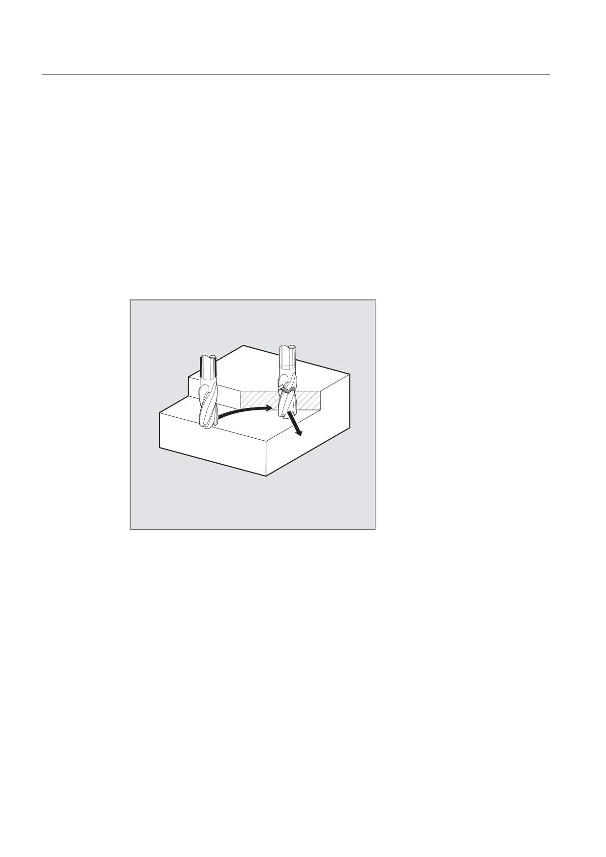
If you interrupt the program run and retract the tool during the machining operation because,
for example, the tool has broken or you wish to check a measurement, you can reposition at
any selected point on the contour under control by the program.
The REPOS command acts in the same way as a subprogram return jump (e.g., via M17).
Blocks programmed after the command in the interrupt routine are not executed.
5(326
For information about interrupting program runs, see also Section "Flexible NC
programming", Chapter "Interrupt routine" in this Programming Manual.
Job Planning
476
Programming Manual, 03/2010, 6FC5398-2BP20-1BA0
Path traversing behavior
8.6 Repositioning to a contour (REPOSA, REPOSL, REPOSQ, REPOSQA, REPOSH, REPOSHA, DISR, DISPR, RMI, RM
Syntax
REPOSA RMI DISPR=…
REPOSA RMB
REPOSA RME
REPOSA RMN
REPOSL RMI DISPR=…
REPOSL RMB
REPOSL RME
REPOSL RMN
REPOSQ RMI DISPR=… DISR=…
REPOSQ RMB DISR=…
REPOSQ RME DISR=…
REPOSQA DISR=…
REPOSH RMI DISPR=… DISR=…
REPOSH RMB DISR=…
REPOSH RME DISR=…
REPOSHA DISR=…
Significance
Approach path
REPOSA
Approach along line on all axes
REPOSL
Approach along line
REPOSQ DISR=…
Approach along quadrant with radius DISR
REPOSQA DISR=…
Approach on all axes along quadrant with radius DISR
REPOSH DISR=…
Approach along semi-circle with diameter DISR
REPOSHA DISR=…
Approach on all axes along semi-circle with diameter DISR
Reapproach point
RMI
Approach interruption point
RMI DISPR=…
Entry point at distance DISPR in mm/inch in front of interruption
point
RMB
Approach block start point
RME
Approach end of block
RME DISPR=…
Approach block end point at distance DISPR in front of end
point
RMN
Approach at nearest path point
A0 B0 C0
Axes in which approach is to be made
Job Planning
Programming Manual, 03/2010, 6FC5398-2BP20-1BA0
477
Path traversing behavior
8.6 Repositioning to a contour (REPOSA, REPOSL, REPOSQ, REPOSQA, REPOSH, REPOSHA, DISR,
DISPR, RMI, RMB, RME, RMN)
Example: Approach along a straight line, REPOSA, REPOSL
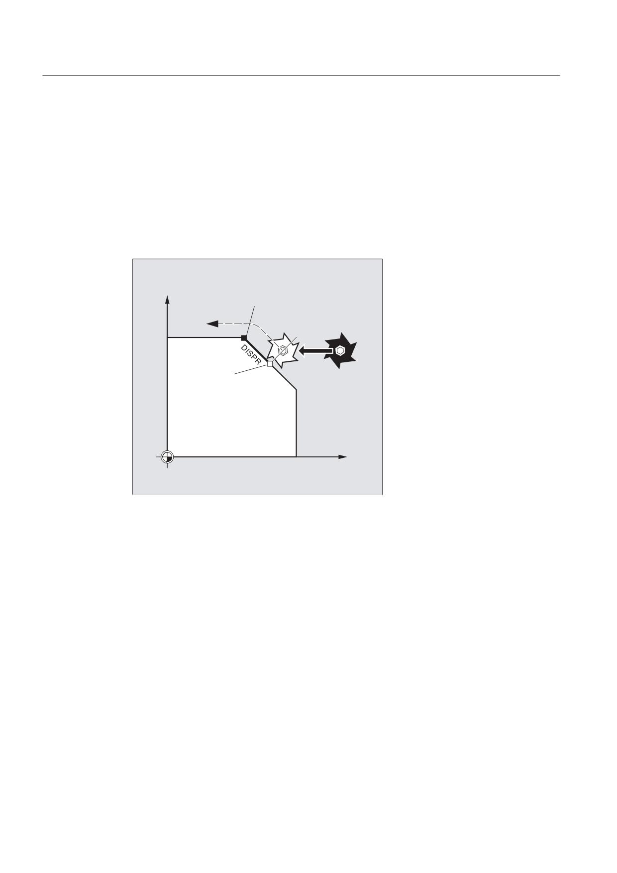
The tool approaches the repositioning point along a straight line.
All axes are automatically traversed with command REPOSA. With REPOSL you can specify
which axes are to be moved.
Example:
REPOSL RMI DISPR=6 F400
or
REPOSA RMI DISPR=6 F400
<
,QWHUUXSWLRQ SRLQW
5(326/
%ORFN VWDUW SRLQW
;
Job Planning
478
Programming Manual, 03/2010, 6FC5398-2BP20-1BA0
Path traversing behavior
8.6 Repositioning to a contour (REPOSA, REPOSL, REPOSQ, REPOSQA, REPOSH, REPOSHA, DISR, DISPR, RMI, RM
Example: Approach in circle quadrant, REPOSQ, REPOSQA
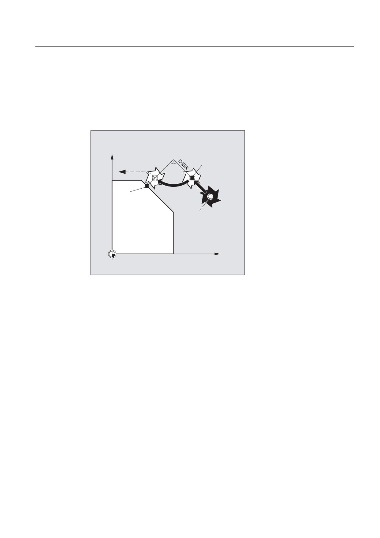
The tool approaches the repositioning point along a quadrant with a radius of DISR=…. The
control system automatically calculates the intermediate point between the start and
repositioning points.
Example:
REPOSQ RMI DISR=10 F400
<
,QWHUPHGLDWH
SRLQW
4
(32 6
5
%ORFN VWDUW SRLQW
6WDUW SRLQW
;
Job Planning
Programming Manual, 03/2010, 6FC5398-2BP20-1BA0
479
Path traversing behavior
8.6 Repositioning to a contour (REPOSA, REPOSL, REPOSQ, REPOSQA, REPOSH, REPOSHA, DISR,
DISPR, RMI, RMB, RME, RMN)
Example: Approach tool in a semicircle, REPOSH, REPOSHA
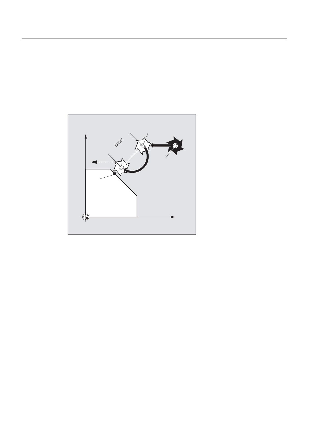
The tool approaches the repositioning point along a semi-circle with a diameter of DISR=….
The control automatically calculates the necessary intermediate point between the start and
repositioning point.
Example:
REPOSH RMI DISR=20 F400
,QWHUPHGLDWH SRLQW
<
6WDUW SRLQW
%ORFN VWDUW SRLQW
;
Job Planning
480
Programming Manual, 03/2010, 6FC5398-2BP20-1BA0
Path traversing behavior
8.6 Repositioning to a contour (REPOSA, REPOSL, REPOSQ, REPOSQA, REPOSH, REPOSHA, DISR, DISPR, RMI, RM
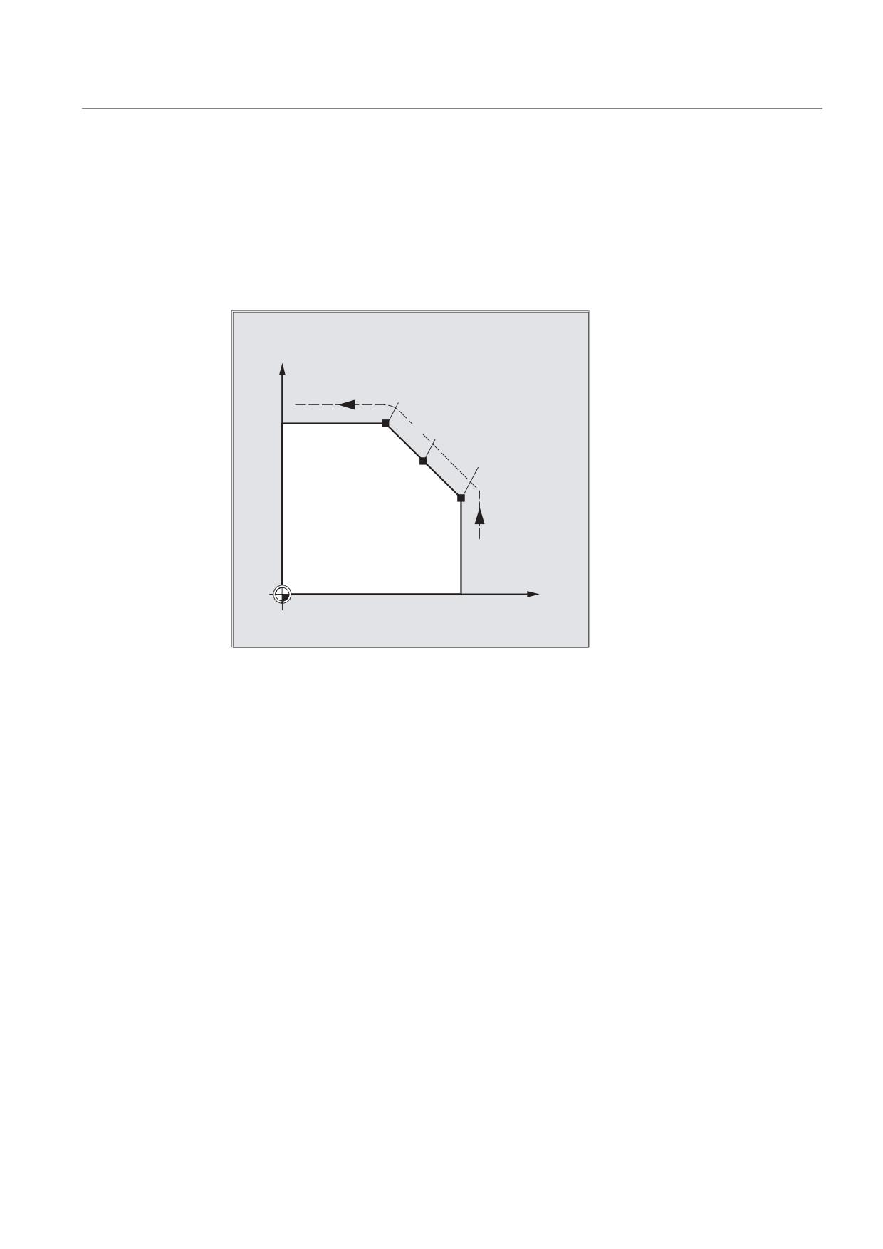
Specifying the repositioning point (not for SERUPRO approaching with RMN)
With reference to the NC block in which the program run has been interrupted, it is possible
to select one of three different repositioning points:
● RMI, interruption point
● RMB, block start point or last end point
● RME, block end point
<
%ORFN HQG SRLQW
,QWHUUXSWLRQ SRLQW
50(
%ORFN VWDUW SRLQW
50,
50%
;
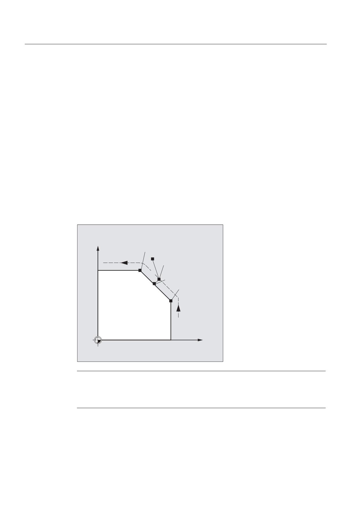
RMI DISPR=… or RME DISPR=… allows you to select a repositioning point which sits before the
interruption point or the block end point.
DISPR=… allows you to describe the contour distance in mm/inch between the repositioning
point and the interruption before the end point. Even for high values, this point cannot be
further away than the block start point.
If no DISPR=… command is programmed, then DISPR=0 applies and with it the interruption point
(with RMI) or the block end point (with RME).
Job Planning
Programming Manual, 03/2010, 6FC5398-2BP20-1BA0
481
Path traversing behavior
8.6 Repositioning to a contour (REPOSA, REPOSL, REPOSQ, REPOSQA, REPOSH, REPOSHA, DISR,
DISPR, RMI, RMB, RME, RMN)
DISPR sign
The sign DISPR is evaluated. In the case of a plus sign, the behavior is as previously.
In the case of a minus sign, approach is behind the interruption point or, with RMB, behind the
block start point.
The distance between interruption point and approach point depends on the value of DISPR.
Even for higher values, this point can lie in the block end point at the maximum.
Sample application:
A sensor will recognize the approach to a clamp. An ASUP is initiated to bypass the clamp.
Afterwards, a negative DISPR is repositioned on one point behind the clamp and the program
is continued.
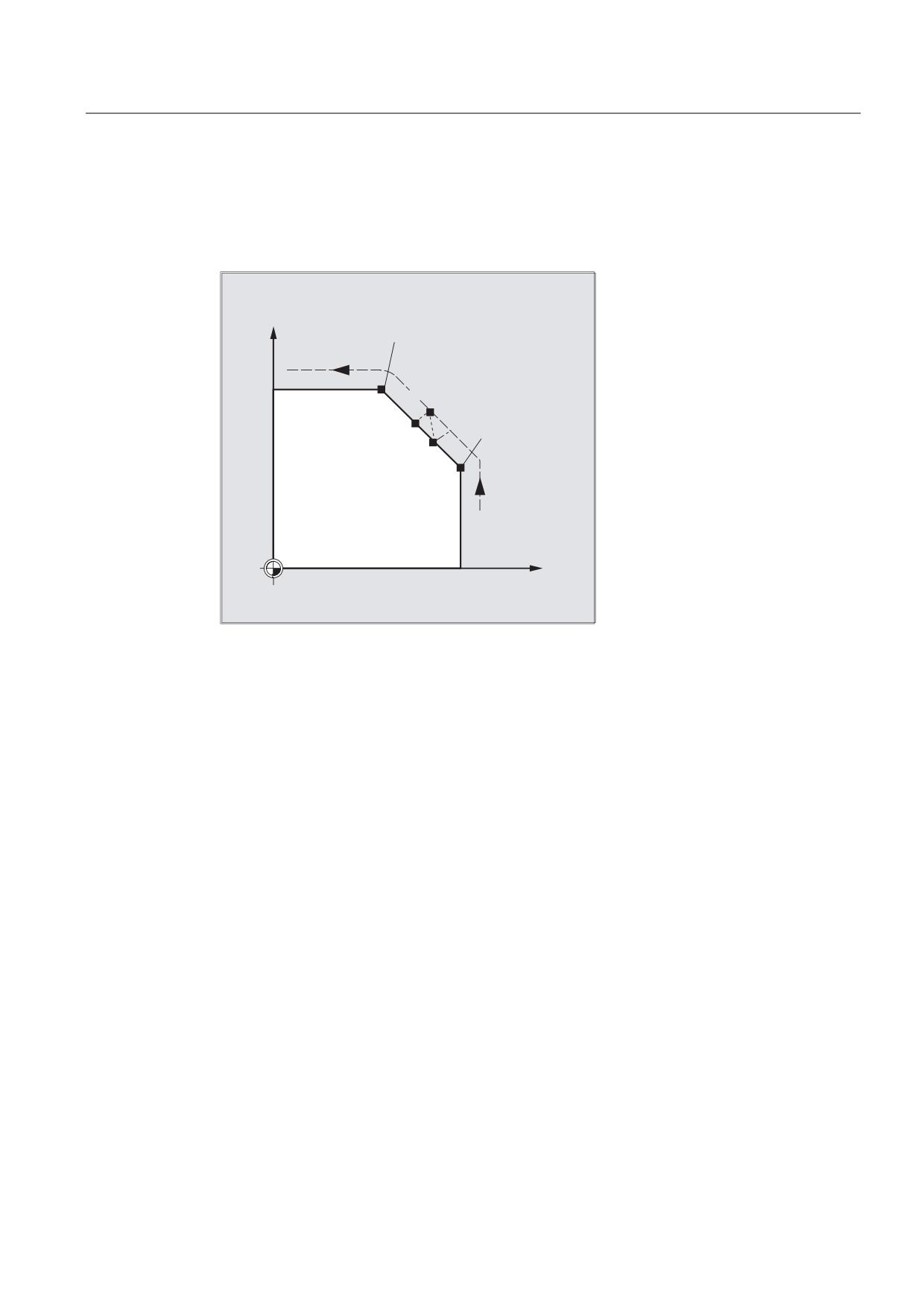
SERUPRO approach with RMN
If abort is forced during machining at any position, the shortest path from the abort point is
approached with SERUPRO approach and RMN so that afterward only the distance-to-go is
processed. The user starts a SERUPRO process at the interruption block and uses the JOG
keys to move in front of the problem component of the target block.
<
%ORFN HQG SRLQW
$FWXDO SRVLWLRQ IRU EORFN VHDUFK
3RVLWLRQ UHDFKHG XVLQJ
-2* NH\
50(
6(58352 DSSURDFK
501
%ORFN VWDUW SRLQW
50,
50%
;
Note
SERUPRO
For SERUPRO, RMI and RMB are identical. RMN is not limited to SERUPRO but is generally
applicable.
Job Planning
482
Programming Manual, 03/2010, 6FC5398-2BP20-1BA0
Path traversing behavior
8.6 Repositioning to a contour (REPOSA, REPOSL, REPOSQ, REPOSQA, REPOSH, REPOSHA, DISR, DISPR, RMI, RM
Approach from the nearest path point RMN
When REPOSA is interpreted, the repositioning block with RMN is not started again in full after
an interruption, but only the distance-to-go processed. The nearest path point of the
interrupted block is approached.
<
%ORFN HQG SRLQW
50(
5HSRVLWLRQLQJ
$68%
501
%ORFN VWDUW SRLQW
50,
50%
;
Status for the valid REPOS mode
The valid REPOS mode of the interrupted block can be read with synchronized actions and
variable $AC_ REPOS_PATH_MODE:
0: Approach not defined
1 RMB: Approach to beginning
2 RMI: Approach to point of interruption
3 RME: Approach to end of block
4 RMN: Approaching to next path point of the interrupted block
Job Planning
Programming Manual, 03/2010, 6FC5398-2BP20-1BA0
483
Path traversing behavior
8.6 Repositioning to a contour (REPOSA, REPOSL, REPOSQ, REPOSQA, REPOSH, REPOSHA, DISR,
DISPR, RMI, RMB, RME, RMN)
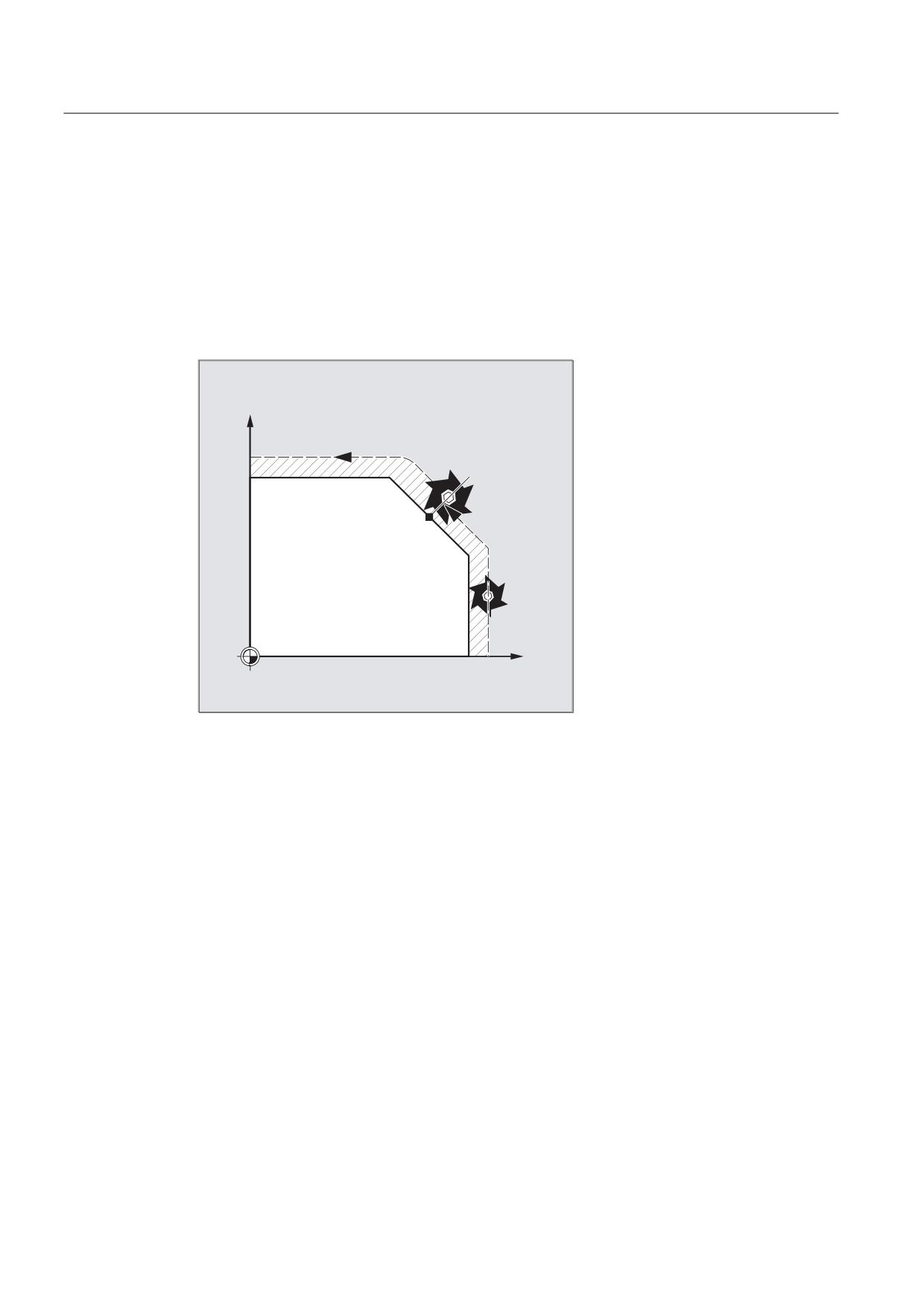
Approaching with a new tool
The following applies if you have stopped the program run due to tool breakage:
When the new D number is programmed, the machining program is continued with modified
tool offset values at the repositioning point.
Where tool offset values have been modified, it may not be possible to reapproach the
interruption point. In such cases, the point closest to the interruption point on the new
contour is approached (possibly modified by DISPR).
<
;
Approach contour
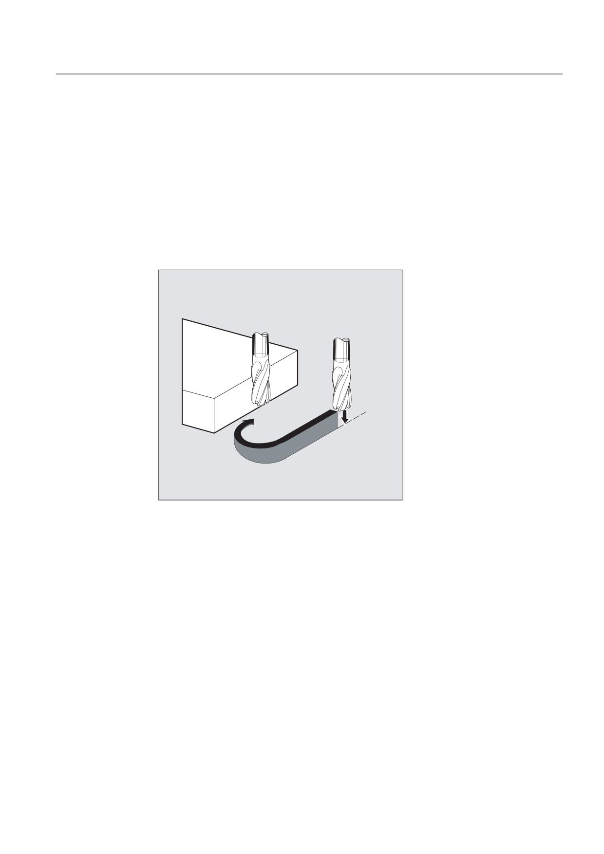
The motion with which the tool is repositioned on the contour can be programmed. Enter
zero for the addresses of the axes to be traversed.
The REPOSA, REPOSQA and REPOSHA commands automatically reposition all axes. Individual
axis names need not be specified.
When the commands REPOSL, REPOSQ and REPOSH are programmed, all geometry axes are
traversed automatically, i.e. they need not be named in the command. All other axes must be
specified in the commands.
Job Planning
484
Programming Manual, 03/2010, 6FC5398-2BP20-1BA0
Path traversing behavior
8.6 Repositioning to a contour (REPOSA, REPOSL, REPOSQ, REPOSQA, REPOSH, REPOSHA, DISR, DISPR, RMI, RM
The following applies to the REPOSH and REPOSQ circular motions:
The circle is traversed in the specified working planes G17 to G19.
If you specify the third geometry axis (infeed direction) in the approach block, the
repositioning point is approached along a helix in case the tool position and programmed
position in the infeed direction do not coincide.
In the following cases, the control automatically switches over to linear approach REPOSL:
● You have not specified a value for DISR.
● No defined approach direction is available (program interruption in a block without travel
information).
● With an approach direction that is perpendicular to the current working plane.
Job Planning
Programming Manual, 03/2010, 6FC5398-2BP20-1BA0
485
Path traversing behavior
8.7 Influencing the motion control
8.7
Influencing the motion control
8.7.1
Percentage jerk correction (JERKLIM)
Function
Using the NC command JERKLIM, the maximum jerk of an axis for path motion - set using
machine data - can be reduced or increased in critical program sections.
Precondition
The acceleration mode SOFT must be active.
Effectiveness
The function is effective:
● In the AUTOMATIC operating modes.
● Only on path axes.
Syntax
JERKLIM[<axis>]=<value>
Meaning
JERKLIM:
Command for jerk correction
<axis>:
Machine axis whose jerk limit value is to be adapted.
<value>
:
Percentage correction value, referred to the configured maximum axis
jerk for path motion (MD32431 $MA_MAX_AX_JERK).
Range of values:
1 ... 200
Value 100 does not influence the jerk.
Note
The behavior of JERKLIM at the end of the part program and channel reset is configured
with bit 0 in machine data MD32320 $MA_DYN_LIMIT_RESET_MASK:
• Bit 0 = 0:
The programmed value for JERKLIM is reset to 100% with channel reset/M30.
• Bit 0 = 1:
The programmed value for JERKLIM is retained beyond the channel reset/M30.
Job Planning
486
Programming Manual, 03/2010, 6FC5398-2BP20-1BA0
Path traversing behavior
8.7 Influencing the motion control
Example
Program code
Comment
N60 JERKLIM[X]=75
; The axis slide in the X direction should only be
accelerated/decelerated with a maximum of 75% of the
jerk permissible for the axis.
8.7.2
Percentage velocity correction (VELOLIM)
Function
Using the NC command VELOLIM, the maximum possible velocity of an axis/spindle in axis
operation or the maximum possible gear unit-stage dependent speed of a spindle in spindle
operation - set using machine data - (speed control mode M3, M4, M5 and positioning mode
SPOS, SPOSA, M19) can be reduced in critical program sections, e.g. to reduce the stress
on the machine or to improve the machining quality.
Effectiveness
The function is effective:
● in the AUTOMATIC operating modes
● on path and positioning axes
● on spindles in spindle/axis operations
Syntax
VELOLIM[<axis/spindle>]=<value>
Job Planning
Programming Manual, 03/2010, 6FC5398-2BP20-1BA0
487
Path traversing behavior
8.7 Influencing the motion control
Meaning
VELOLIM:
Command for velocity correction
<axis/spindle>:
Machine axis or spindle whose velocity or speed limit value should
be adapted.
VELOLIM for spindles
Using machine data (MD30455 $MA_MISC_FUNCTION_MASK,
bit 6), when programming in the part program, it can be set as to
whether VELOLIM is effective independent of whether used as
spindle or axis (bit 6 = 1) - or is able to be programmed separately
for each operating mode (bit 6 = 0). If they are to be separately
effective, then the selection is made using the identifier when
programming:
• Spindle identifier S<n> for spindle operating modes
• Axis identifier, e.g. "C", for axis operation
<value>:
Percentage correction value
The correction value refers to:
• for axes / spindles in axis operation (if MD30455 bit 6 = 0):
to the configured maximum axis velocity
(MD32000 $MA_MAX_AX_VELO).
• for spindles in spindle or axis operation (if MD30455 bit 6 = 1):
to the maximum speed of the active gear unit stage
(MD35130 $MA_GEAR_STEP_MAX_VELO_LIMIT[<n>])
Range of values:
1 ... 100
The value 100 does not influence the velocity or speed.
Note
Behavior at the end of the part program and for a channel reset
The behavior of VELOLIM at the end of the part program and channel reset is configured
with bit 0 in machine data MD32320 $MA_DYN_LIMIT_RESET_MASK:
• Bit 0 = 0:
The programmed value for VELOLIM is reset to 100% with channel reset/M30.
• Bit 0 = 1:
The programmed value for VELOLIM is retained beyond the channel reset/M30.
Job Planning
488
Programming Manual, 03/2010, 6FC5398-2BP20-1BA0
Path traversing behavior
8.7 Influencing the motion control
Note
VELOLIM for spindles in synchronized actions
When programming VELOLIM in synchronized actions, a distinction is not made between
spindle and axis operation. Independent of the identifiers used when programming, the
speed in spindle operation and the velocity in axis operation are limited to the same extent.
Diagnostics
VELOLIM diagnostics in spindle operation
Active speed limiting using VELOLIM (less than 100 %) can be identified in spindle operation
by reading the system variables $AC_SMAXVELO and $AC_SMAXVELO_INFO.
In the case of limiting, $AC_SMAXVELO supplies the speed limit generated by VELOLIM. In
this case, variable $AC_SMAXVELO_INFO returns the value "16" as identifier for the cause
of the limit VELOLIM.
Examples
Example 1: Velocity limiting, machine axis
Program code
Comment
N70 VELOLIM[X]=80
; The axis slide in the X direction should only be
traversed with a maximum of 80% of the velocity
permissible for the axis.
Example 2: Speed limiting, spindle
Program code
Comment
N05 VELOLIM[S1]=90
; Limiting the maximum speed of spindle 1 to 90% of
1000 rpm.
N50 VELOLIM[C]=45
; Limiting the speed to 45% of 1000 rpm, C is the axis
identifier of S1.
Job Planning
Programming Manual, 03/2010, 6FC5398-2BP20-1BA0
489
Path traversing behavior
8.7 Influencing the motion control
Configuring data for spindle 1 (AX5):
MD35130 $MA_GEAR_STEP_MAX_VELO_LIMIT[1,AX5]=1000
; Maximum speed of
gear unit stage 1 =
1000 rpm
MD30455 $MA_MISC_FUNCTION_MASK[AX5] = 64
; Bit 6 = 1:
Programming VELOLIM
acts together for
spindle and axis
operation
independent of the
programmed
identifier.
8.7.3
Program example for JERKLIM and VELOLIM
The following program presents an application example for the percentage jerk and velocity
limit:
Program code
Comments
N1000 G0 X0 Y0 F10000 SOFT G64
N1100 G1 X20 RNDM=5 ACC[X]=20
ACC[Y]=30
N1200 G1 Y20 VELOLIM[X]=5
; The axis slide in the X direction should
only be traversed with max. 5% of the
velocity permissible for the axis.
JERKLIM[Y]=200
; The axis slide in the Y direction can be
accelerated/decelerated with max. 200% of
the jerk permissible for the axis.
N1300 G1 X0 JERKLIM[X]=2
; The axis slide in the X direction should
only be accelerated/decelerated with max.
2% of the jerk permissible for the axis.
N1400 G1 Y0
M30
Job Planning
490
Programming Manual, 03/2010, 6FC5398-2BP20-1BA0
Path traversing behavior
8.8 Programmable contour/orientation tolerance (CTOL, OTOL, ATOL)
8.8
Programmable contour/orientation tolerance (CTOL, OTOL, ATOL)
Function
The CTOL, OTOL, and ATOL commands can be used to adapt the machining tolerances defined
for the compressor functions (COMPON, COMPCURV, COMPCAD), the smoothing types
G642, G643, G645, OST, and the orientation ORISON using machine and setting data in the
NC program.
The programmed values are valid until they are reprogrammed or deleted by means of the
assignment of a negative value. They are also deleted at the end of a program, in the event
of a channel reset, a mode group reset, an NCK reset (warm restart), and POWER ON (cold
restart). On deletion of these values, the values from the machine and setting data are
restored.
Syntax
CTOL=<value>
OTOL=<value>
ATOL[<axis>]=<value>
Significance
CTOL
Command for programming the contour tolerance
CTOL is valid for:
• All compressor functions
• All rounding types except G641 and G644
<value>:
The value for the contour tolerance is specified as a length.
Type:
REAL
Unit:
inch/mm (dependent on the current dimensions setting)
OTOL
Command for programming the orientation tolerance
OTOL is valid for:
• All compressor functions
• ORISON orientation smoothing
• All rounding types except G641, G644, OSD
<value>:
The value for the orientation tolerance is specified as an angle.
Type:
REAL
Unit:
degrees
Job Planning
Programming Manual, 03/2010, 6FC5398-2BP20-1BA0
491
Path traversing behavior
8.8 Programmable contour/orientation tolerance (CTOL, OTOL, ATOL)
ATOL
Command for programming an axis-specific tolerance
ATOL is valid for:
• All compressor functions
• ORISON orientation smoothing
• All rounding types except G641, G644, OSD
<axis>:
Name of the axis for which an axis tolerance is to be programmed
<value>
:
The value for the axis tolerance will be specified as a length or an
angle dependent on the axis type (linear or rotary axis).
Type:
REAL
Unit:
for linear axes:
inch/mm (dependent on the
current dimensions setting)
for rotary axes:
degrees
Note
CTOL and OTOL have priority over ATOL.
General conditions
Scaling frames
Scaling frames affect programmed tolerances in the same way as axis positions; in other
words, the relative tolerance remains the same.
Example
Program code
Comment
COMPCAD G645 G1 F10000
; Activate COMPCAD compressor function.
X... Y... Z...
; The machine and setting data is applied here.
X... Y... Z...
X... Y... Z...
CTOL=0.02
; A contour tolerance of 0.02 mm is applied
starting from here.
X... Y... Z...
X... Y... Z...
X... Y... Z...
ASCALE X0.25 Y0.25 Z0.25
; A contour tolerance of 0.005 mm is applied
starting from here.
X... Y... Z...
X... Y... Z...
X... Y... Z...
Job Planning
492
Programming Manual, 03/2010, 6FC5398-2BP20-1BA0
Path traversing behavior
8.8 Programmable contour/orientation tolerance (CTOL, OTOL, ATOL)
Program code
Comment
CTOL=-1
; The machine and setting data is applied again
starting from here.
X... Y... Z...
X... Y... Z...
X... Y... Z...
Further information
Read tolerance values
For more advanced applications or for diagnostics, the currently valid tolerances for the
compressor functions (COMPON, COMPCURV, COMPCAD), the smoothing types G642,
G643, G645, OST, and the orientation smoothing ORISON can be read via system variables
irrespective of how they might have come about.
● In synchronized actions or with preprocessing stop in the part program via system
variables:
$AC_CTOL
Contour tolerance effective when the current main
run record was preprocessed.
If no contour tolerance is effective, $AC_CTOL will
return the root from the sum of the squares of the
tolerances of the geometry axes.
$AC_OTOL
Orientation tolerance effective when the current main
run record was preprocessed.
If no orientation tolerance is effective, $AC_OTOL will
return the root from the sum of the squares of the
tolerances of the orientation axes during active
orientation transformation. Otherwise, it will return
the value "-1".
$AA_ATOL[<axis>]
Axis tolerance effective when the current main run
record was preprocessed.
If no contour tolerance is active, $AA_ATOL[<geometry
axis>] will return the contour tolerance divided by the
root of the number of geometry axes.
If an orientation tolerance and an orientation
transformation are active $AA_ATOL[<orientation
axis>] will return the orientation tolerance divided by
the root of the number of orientation axes.
Job Planning
Programming Manual, 03/2010, 6FC5398-2BP20-1BA0
493
Path traversing behavior
8.8 Programmable contour/orientation tolerance (CTOL, OTOL, ATOL)
Note
If no tolerance values have been programmed, the $A variables will not be differentiated
sufficiently to distinguish potential differences in the tolerances of the individual functions,
since they can only declare one value.
Circumstances like this can occur if the machine data and the setting data set different
tolerances for compressor functions, smoothing and orientation smoothing. The variables
then return the greatest value prevailing with regard to the currently active functions.
if, for example, a compressor function is active with an orientation tolerance of 0.1° and
ORISON orientation smoothing with 1°, the $AC_OTOL variable will return the value "1". If
orientation smoothing is deactivated, only the value "0.1" will remain to be read.
● Without preprocessing stop in the part program via system variables:
$P_CTOL
Programmed contour tolerance
$P_OTOL
Programmed orientation tolerance
$PA_ATOL
Programmed axis tolerance
Note
If no tolerance values have been programmed, the $P variables will return the value "-1".
Job Planning
494
Programming Manual, 03/2010, 6FC5398-2BP20-1BA0
Path traversing behavior
8.9 Tolerance for G0 motion (STOLF)
8.9
Tolerance for G0 motion (STOLF)
G0 tolerance factor
G0 motion (rapid traverse, infeed motion), contrary to workpiece machining, can be
implemented with a higher tolerance. This has the advantage that the execution times for G0
motion are shortened.
For G0 motion, the tolerances are set by configuring the G0 tolerance factor
(MD20560 $MC_G0_TOLERANCE_FACTOR).
The G0 tolerance factor is only effective, if:
● One of the following functions is active:
- Compressor function: COMPON, COMPCURV and COMPCAD
- Smoothing functions: G642 and G645
- Orientation smoothing: OST
- Orientation smoothing: ORISON
- Smoothing for path-relevant orientation: ORIPATH
● several (≥ 2) consecutive G0 blocks.
For a single G0 block, the G0 tolerance factor is not effective, as at the transition from a
non G0 motion to a G0 motion (and vice versa), the "lower tolerance" always applies
(workpiece machining tolerance)!
Function
The configured G0 tolerance factor (MD20560) can be temporarily overwritten by
programming STOLF in the part program. In this case, the value in MD20560 is not changed.
After a reset or end of part program, the configured tolerance factor is effective again.
Syntax
STOLF=<tolerance factor>
Meaning
STOLF:
Command to program the G0 tolerance factor
<tolerance factor>:
G0 tolerance factor
The factor can either be greater than 1 or less than 1.
However, normally higher tolerances can be set for G0 motion.
For STOLF=1.0 (this corresponds to the configured standard
value), for G0 motion, the same tolerances are effective as for
non-G0 motion.
Job Planning
Programming Manual, 03/2010, 6FC5398-2BP20-1BA0
495
Path traversing behavior
8.9 Tolerance for G0 motion (STOLF)
System variables
The G0 tolerance factor, effective in the part program or in the actual IPO block, can be read
using system variables.
● In synchronized actions or with preprocessing stop in the part program via system
variable:
$AC_STOLF
Active G0 tolerance factor
G0 tolerance factor, which was effective when processing the
actual main run block.
● Without preprocessing stop in the part program via system variable:
$P_STOLF
Programmed G0 tolerance factor
If no value with STOLF is programmed in the active part program, then these two system
variables supply the value set using MD20560 $MC_G0_TOLERANCE_FACTOR.
If no rapid traverse (G0) is active in a block, then these system variables always supply a
value of 1.
Example
Program code
Comment
COMPCAD G645 G1 F10000
; Compressor function COMPCAD
X... Y... Z...
; The machine and setting data apply here.
X... Y... Z...
X... Y... Z...
G0 X... Y... Z...
G0 X... Y... Z...
; Machine data $MC_G0_TOLERANCE_FACTOR (e.g. =3), is
effective here, i.e. a smoothing tolerance of
$MC_G0_TOLERANCE_FACTOR*$MA_COMPRESS_POS_TOL.
CTOL=0.02
STOLF=4
G1 X... Y... Z...
; A contour tolerance of 0.02mm is applied starting
from here.
X... Y... Z...
X... Y... Z...
G0 X... Y... Z...
X... Y... Z...
; From here, a G0 tolerance factor of 4 applies, i.e. a
contour tolerance of 0.08mm.
Job Planning
496
Programming Manual, 03/2010, 6FC5398-2BP20-1BA0
Axis couplings
9
9.1
Coupled motion (TRAILON, TRAILOF)
Function
When a defined leading axis is moved, the coupled motion axes (= following axes) assigned
to it traverse through the distances described by the leading axis, allowing for a coupling
factor.
Together, the leading axis and following axis represent coupled axes.
Applications
● Traversal of an axis by means of a simulated axis. The leading axis is a simulated axis
and the coupled axis a real axis. In this way, the real axis can be traversed as a function
of the coupling factor.
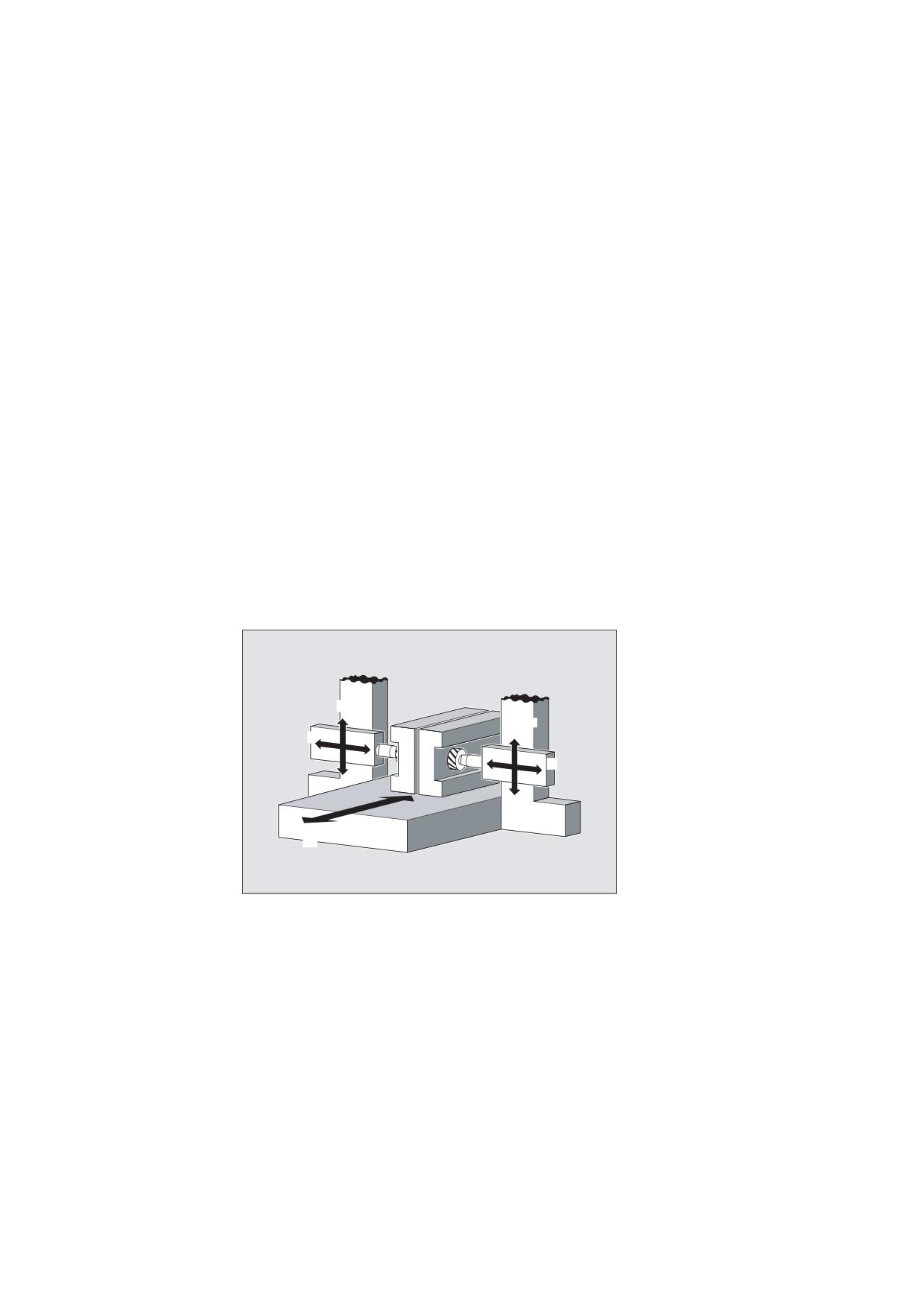
● Two-sided machining with 2 coupled motion groups:
1. Leading axis Y, coupled motion axis V
2. Leading axis Z, coupled motion axis W
$[LV
<
$[LV
9
$[LV
=
$[LV
:
$[LV
;
Syntax
TRAILON(<following axis>,<leading axis>,<coupling factor>)
TRAILOF(<following axis>,<leading axis>,<leading axis 2>)
TRAILOF(<following axis>)
Job Planning
Programming Manual, 03/2010, 6FC5398-2BP20-1BA0
497
Axis couplings
9.1 Coupled motion (TRAILON, TRAILOF)
Significance
TRAILON
Command for activating and defining a coupled axis grouping
Active:
modal
<following axis>
Parameter 1: Axis name of trailing axis
Note:
A coupled-motion axis can also act as the leading axis for other
coupled-motion axes. In this way, it is possible to create a range
of different coupled axis groupings.
<leading axis>
Parameter 2: Axis name of trailing axis
<coupling factor>
Parameter 3: Coupling factor
The coupling factor specifies the desired relationship between the
paths of the coupled-motion axis and the leading axis:
<coupling factor> = path of coupled-motion axis/path of leading
axis
Type: REAL
Default:
1
The input of a negative value causes the master and coupled axes
to traverse in opposition.
If a coupling factor is not programmed, then coupling factor 1
automatically applies.
TRAILOF
Command for deactivating a coupled axis grouping
Effective:
modal
TRAILOF with 2 parameters deactivates only the coupling to the
specified leading axis:
TRAILOF(<following axis>,<leading axis>)
If a coupled-motion axis has 2 leading axes, TRAILOF can be called
with 3 parameters to deactivate both couplings.
TRAILOF(<following axis>,<leading axis>,<leading axis 2>)
Programming TRAILOF without specifying a leading axis produces the
same result:
TRAILOF(<following axis>)
Note
Coupled axis motion is always executed in the base coordinate system (BCS).
The number of coupled axis groupings which may be simultaneously activated is limited only
by the maximum possible number of combinations of axes on the machine.
Job Planning
498
Programming Manual, 03/2010, 6FC5398-2BP20-1BA0
Axis couplings
9.1 Coupled motion (TRAILON, TRAILOF)
Example
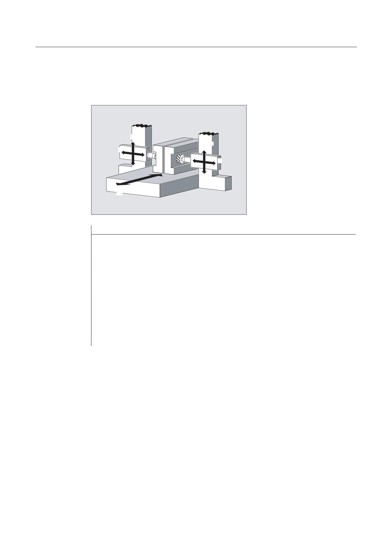
The workpiece is to be machined on two sides with the axis configuration shown in the
diagram. To do this, you create two combinations of coupled axes.
$[LV
<
$[LV
$[LV
9
=
$[LV
:
$[LV
;
Program code
Comments
…
N100 TRAILON(V,Y)
; Activation of 1st coupled axis grouping
N110 TRAILON(W,Z,-1)
; Activation of 2nd coupled axis grouping, Negative
coupling factor: Coupled-motion axis traverses in the
opposite direction from leading axis.
N120 G0 Z10
; Infeed of Z and W axes in opposite axial directions.
N130 G0 Y20
; Infeed of Y and V axes in same axis direction.
…
N200 G1 Y22 V25 F200
; Overlaying of a dependent and independent movement of
coupled motion axis V.
…
TRAILOF(V,Y)
; Deactivation of 1st coupled axis grouping.
TRAILOF(W,Z)
; Deactivation of 2nd coupled axis grouping.
Further Information
Axis types
A coupled axis grouping can consist of any desired combinations of linear and rotary axes. A
simulated axis can also be defined as a leading axis.
Coupled-motion axes
Up to two leading axes can be assigned simultaneously to a trailing axis. The assignment is
made in different combinations of coupled axes.
A coupled-motion axis can be programmed with the full range of available motion commands
(G0, G1, G2, G3, etc.). The coupled axis not only traverses the independently defined paths, but
also those derived from its leading axes on the basis of coupling factors.
Job Planning
Programming Manual, 03/2010, 6FC5398-2BP20-1BA0
499
Axis couplings
9.1 Coupled motion (TRAILON, TRAILOF)
Dynamics limit
The dynamics limit is dependent on the type of activation of the coupled axis grouping:
● Activation in part program
If activation is performed in the part program and all leading axes are active as program
axes in the activated channel, the dynamic response of all coupled-motion axes is taken
into account during traversing of the leading axis to avoid overloading the coupled-motion
axes.
If activation is performed in the part program with leading axes that are not active as
program axes in the activating channel ($AA_TYP ≠ 1), then the dynamic response of the
coupled-motion axes is not taken into account during traversing of the leading axis. This
can cause the overloading of coupled-motion axes with a dynamic response which is less
than that required for the coupling.
● Activation in synchronized action
If activation is performed in a synchronized action, the dynamic response of the coupled-
motion axes is not taken into account during traversing of the leading axis. This can
cause the overloading of coupled-motion axes with a dynamic response which is less
than that required for the coupling.
CAUTION
If a coupled axis grouping is activated:
• in synchronized actions
• in the part program with leading axes that are not program axes in the channel of the
coupled-motion axes
it is the specific responsibility of the user/machine manufacturer to take suitable action
to ensure that the traversing of the leading axis will not cause the overloading of the
coupled-motion axes.
Coupling status
The coupling status of an axis can be checked in the part program with the system variable:
$AA_COUP_ACT[<axis>]
Value
Significance
0
No coupling active
8
Coupled motion active
Job Planning
500
Programming Manual, 03/2010, 6FC5398-2BP20-1BA0
Axis couplings
9.2 Curve tables (CTAB)
9.2
Curve tables (CTAB)
Function
Curve tables can be used to program position and velocity relationships between two axes
(leading and following axis). Curve tables are defined in the part program.
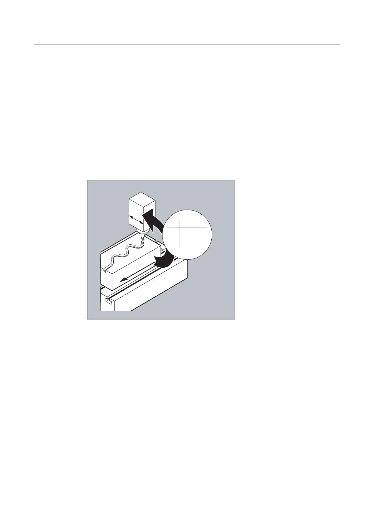
Application
Curve tables replace mechanical cams. The curve table forms the basis for the axial master
value coupling by creating the functional relationship between the leading and the following
value: With appropriate programming, the control calculates a polynomial that corresponds
to the cam from the relative positions of the leading and following axes.
<
[
\
D D D[
D D[
;
Job Planning
Programming Manual, 03/2010, 6FC5398-2BP20-1BA0
501
Axis couplings
9.2 Curve tables (CTAB)
9.2.1
Define curve tables (CTABDEF, CATBEND)
Function
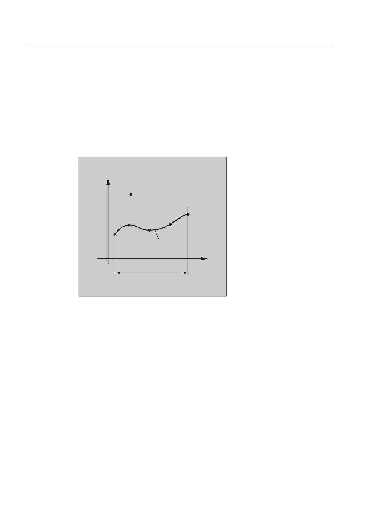
A curve table represents a part program or a section of a part program enclosed by CTABDEF
at the start and CTABEND at the end.
Within this part program section, unique following axis positions are assigned to individual
positions of the leading axis using motion operations; these following axis positions are used
as intermediate points when calculating the curve definition in the form of a polynomial up to
the 5th order.
6ODYH YDOXH
LQWHUPHGLDWH SRLQW
&XUYH WUDFH
0DVWHU YDOXH
'HILQLWLRQ UDQJH
6WDUWLQJ YDOXH
(QG YDOXH
Condition
The MD must be configured accordingly to ensure that sufficient memory space is reserved
for the definition of curve tables (→ machine manufacturer).
Syntax
CTABDEF(<following axis>,<leading axis>,<n>,<periodicity>[,<memory
location>])
CTABEND
Job Planning
502
Programming Manual, 03/2010, 6FC5398-2BP20-1BA0
Axis couplings
9.2 Curve tables (CTAB)
Significance
CTABDEF( )
Start of curve table definition
CTABEND
End of curve table definition
<following axis>
Axis whose motion is to be calculated using the curve table
<leading axis>
Axis providing the master values for the calculation of the following
axis motion
<n>
Number (ID) of curve table
The number of a curve table is unique and independent of the
memory location. It is not possible for there to be tables with the
same number in the static and dynamic NC memory.
<periodicity>
Table periodicity
0
Table is non-periodic (table is processed only once, even for
rotary axes)
1
Table is periodic with regard to the leading axis
2
Table is periodic with regard to leading axis and following axis
<memory location>
Specification of memory location (optional)
"SRAM"
The curve table is created in the static NC memory.
"DRAM"
The curve table is created in the dynamic NC memory.
Note:
If a value is not programmed for this parameter, the default memory
location set with
MD20905 $MC_CTAB_DEFAULT_MEMORY_TYPE is used.
Note
Overwrite
A curve table is overwritten as soon as its number (<n>) is used in another table definition
(exception: the curve table is in active in an axis coupling or locked with CTABLOCK). No
warning is output when curve tables are overwritten.
Job Planning
Programming Manual, 03/2010, 6FC5398-2BP20-1BA0
503
Axis couplings
9.2 Curve tables (CTAB)
Examples
Example 1: Program section as curve table definition
A program section is to be used unchanged for defining a curve table. The STOPRE command
for preprocessing stop can remain and is reactivated immediately as soon as the program
section is no longer being used for table definition and CTABDEF and CTABEND have been
removed.
Program code
Comments
…
CTABDEF(Y,X,1,1)
; Definition of a curve table.
…
IF NOT ($P_CTABDEF)
STOPRE
ENDIF
…
CTABEND
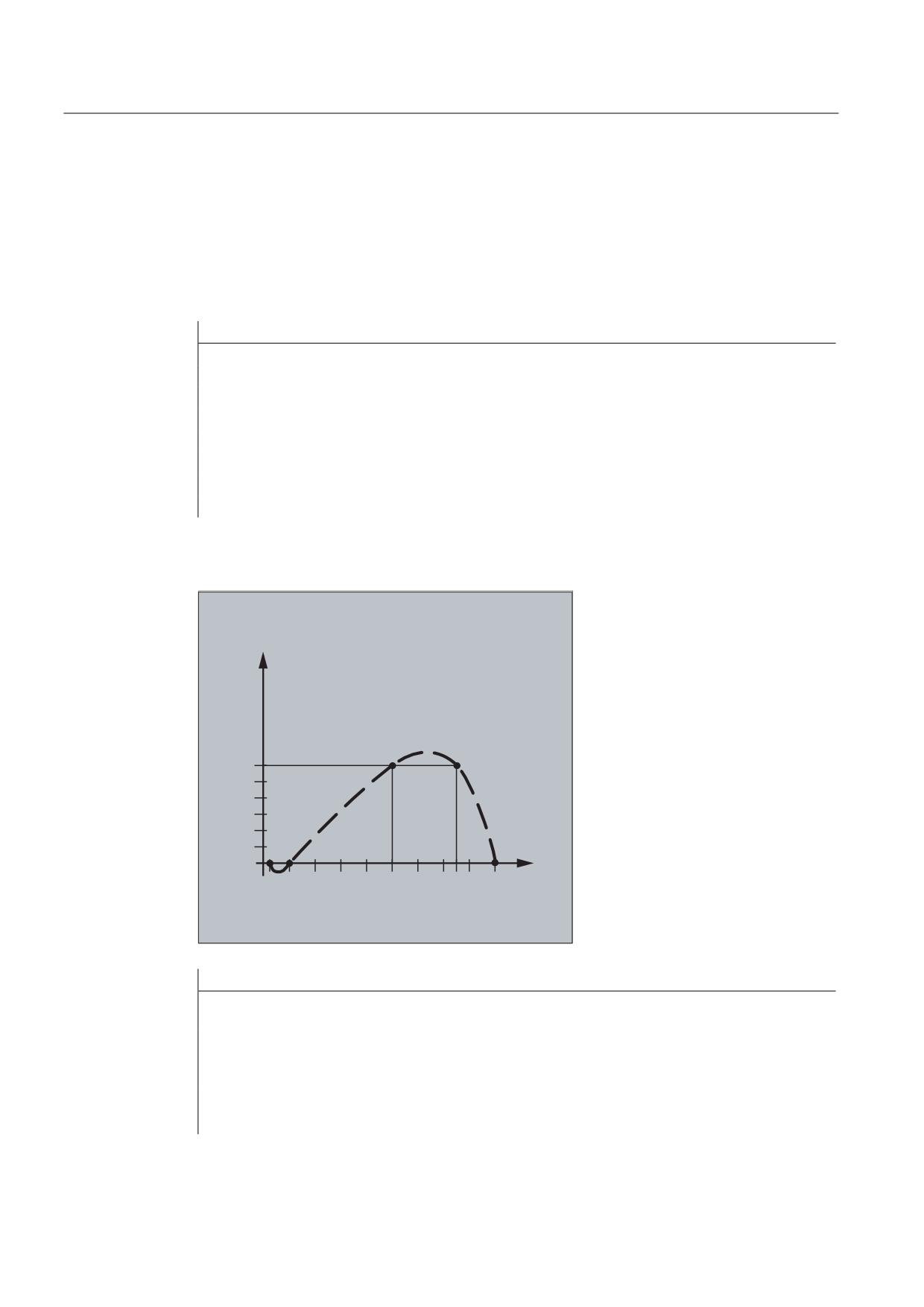
Example 2: Definition of a non-periodic curve table
<
;
Program code
Comments
N100 CTABDEF(Y,X,3,0)
; Beginning of the definition of a ;non-periodic curve
table with number 3.
N110 X0 Y0
; 1st motion operation, defines the starting values and
1st intermediate point:
Master value: 0, Following value: 0
N120 X20 Y0
; 2nd intermediate point
Master value: 0…20, Following value: starting value…0
Job Planning
504
Programming Manual, 03/2010, 6FC5398-2BP20-1BA0
Axis couplings
9.2 Curve tables (CTAB)
Program code
Comments
N130 X100 Y6
;
3rd intermediate point:
Master value: 20…100, Following value: 0 to 6
N140 X150 Y6
;
4th intermediate point:
Master value: 100…150, Following value: 6 to 6
N150 X180 Y0
;
5th intermediate point:
Master value: 150…180, Following value: 6 to 0
N200 CTABEND
; End of definition. The curve table is generated in
its internal representation as a polynomial of up to
the 5th order. The calculation of the curve
definition with the specified intermediate points is
dependent on the modally selected interpolation type
(circular, linear, spline interpolation). The part
program state before starting the definition is
restored.
Example 3: Definition of a periodic curve table
Definition of a periodic curve table with number 2, master value range 0 to 360, following
axis motion from 0 to 45 and back to 0:
Program code
Comments
N10 DEF REAL DEPPOS
N20 DEF REAL GRADIENT
N30 CTABDEF(Y,X,2,1)
; Start of definition
N40 G1 X=0 Y=0
N50 POLY
N60 PO[X]=(45.0)
N70 PO[X]=(90.0) PO[Y]=(45.0,135.0,-90)
N80 PO[X]=(270.0)
N90 PO[X]=(315.0) PO[Y]=(0.0,-135.0,90)
N100 PO[X]=(360.0)
N110 CTABEND
; End of definition
;Test of the curve by coupling Y to X:
N120 G1 F1000 X0
N130 LEADON(Y,X,2)
N140 X360
N150 X0
N160 LEADOF(Y,X)
N170 DEPPOS=CTAB(75.0,2,GRADIENT)
; Read the table function for
master value 75.0.
N180 G0 X75 Y=DEPPOS
; Positioning leading and following
axes.
;After activating the coupling, no synchronization of the following axis is
required.
N190 LEADON(Y,X,2)
N200 G1 X110 F1000
N210 LEADOF(Y,X)
N220 M30
Job Planning
Programming Manual, 03/2010, 6FC5398-2BP20-1BA0
505
Axis couplings
9.2 Curve tables (CTAB)
Further information
Starting and end value of the curve table
The starting value for the beginning of the definition range of the curve table are the first
associated axis positions specified (the first traverse statement) within the curve table
definition. The end value of the definition range of the curve table is determined in
accordance with the last traverse command.
Available language scope
Within the definition of the curve table, you have use of the entire NC language.
Note
The following entries are not permitted in curve table definitions:
• Preprocessing stop
• Jumps in the leading axis movement (e.g. on changing transformations)
• Traverse statement for the following axis only
• Reversal of the leading axis, i.e. position of the leading axis must always be unique
• CTABDEF and CTABEND operation on different program levels.
Effectiveness of modal operations
All modal statements that are made within the curve table definition are invalid when the
table definition is completed. The part program in which the table definition is made is
therefore before and after the table definition in the same state.
Assignments to R-parameters
Assignments to R-parameters in the table definition are reset after CTABEND.
Example:
Program code
Comments
R10=5 R11=20
; R10=5
CTABDEF
G1 X=10 Y=20 F1000
R10=R11+5
; R10=25
X=R10
CTABEND
; R10=5
Job Planning
506
Programming Manual, 03/2010, 6FC5398-2BP20-1BA0
Axis couplings
9.2 Curve tables (CTAB)
Activating ASPLINE, BSPLINE, CSPLINE
If an ASPLINE, BSPLINE or CSPLINE is activated within a curve table definition CTABDEF ...
CTABEND, at least one starting point should be programmed before this spline activation.
Immediate activation after CTABDEF should be avoided, otherwise the spline will depend on
the current axis position before the curve table definition.
Example:
Program code
CTABDEF(Y,X,1,0)
X0 Y0
ASPLINE
X=5 Y=10
X10 Y40
CTABEND
Repeated use of curve tables
The functional relationship between the leading axis and the following axis calculated using
the curve table will be retained under the selected table number after the end of the part
program and POWER OFF if the table has been saved to the static NC memory (SRAM).
A table created in the dynamic memory (DRAM) will be deleted on POWER ON and may
have to be regenerated.
Once created, the curve table can be applied to any axis combinations of leading and
following axis and is independent of the axes used to create the curve table.
Overwriting curve tables
A curve table is overwritten as soon as its number is used in another table definition.
Exception: A curve table is either active in an axis coupling or locked with CTABLOCK.
Note
No warning is output when curve tables are overwritten.
Curve table definition active?
The $P_CTABDEF system variable can be used at any time in the part program to check
whether a curve table definition is active.
Revoking the curve table definition
Once the operations relating to the curve table definition have been excluded, the part
program section can be used as a real part program again.
Job Planning
Programming Manual, 03/2010, 6FC5398-2BP20-1BA0
507
Axis couplings
9.2 Curve tables (CTAB)
Loading curve tables using "Execution from external source"
If curve tables are executed from an external source, the selection of the size of the reload
buffer (DRAM) in MD18360 $MN_MM_EXT_PROG_BUFFER_SIZE has to support the
simultaneous storage of the entire curve table definition in the reload buffer. If it is not, part
program processing will be canceled with an alarm.
Jumps in the following axis
Depending on the setting in machine data
MD20900 $MC_CTAB_ENABLE_NO_LEADMOTION,
jumps in the following axis may be tolerated if a movement is missing in the leading axis.
9.2.2
Check for presence of curve table (CTABEXISTS)
Function
The CTABEXISTS command can be used to check if a specific curve table number is present in
the NC memory.
Syntax
CTABEXISTS(<n>)
Significance
CTABEXISTS
Checks for the presence of curve table number <n> in the static or
dynamic NC memory.
0
Table does not exist
1
Table exists
<n>
Number (ID) of curve table
9.2.3
Delete curve tables (CTABDEL)
Function
CTABDEL can be used to delete curve tables.
Note
Curve tables that are active in an axis coupling cannot be deleted.
Job Planning
508
Programming Manual, 03/2010, 6FC5398-2BP20-1BA0
Axis couplings
9.2 Curve tables (CTAB)
Syntax
CTABDEL(<n>)
CTABDEL(<n>,<m>)
CTABDEL(<n>,<m>,<memory location>)
CTABDEL ()
CTABDEL(,,<memory location>)
Significance
CTABDEL
Command for deleting curve tables
<n>
Number (ID) of the curve table to be deleted
When a curve table range CTABDEL(<n>,<m>) is deleted, <n> is used
to specify the number of the first curve table in the range.
<m>
When a curve table range CTABDEL(<n>,<m>) is deleted, <m> is used
to specify the number of the last curve table in the range.
<m> has to be greater than <n>.
<memory location>
Specification of memory location (optional)
In the case of deletion without a memory location being specified,
the specified curve tables are deleted in the static and the dynamic
NC memory.
In the case of deletion with a memory location being specified, of the
specified curve tables, only those located in the specified memory
location are deleted. The rest are retained.
"SRAM"
Deletion in the static NC memory
"DRAM"
Deletion in the dynamic NC memory
If CTABDEL is programmed without specification of the curve table to be deleted, then all curve
tables or all curve tables in the specified memory will be deleted:
CTABDEL ()
Deletes all curve tables in the static and the dynamic NC
memory
CTABDEL(,,"SRAM")
Deletes all curve tables in the static NC memory
CTABDEL(,,"DRAM")
Deletes all curve tables in the dynamic NC memory
Note
If, in the case of multiple deletion with CTABDEL(<n>,<m>) or CTABDEL(), at least one of the of
the curve tables to be deleted is active in a coupling, the delete command will not be
executed; in other words, none of the addressed curve tables will be deleted.
Job Planning
Programming Manual, 03/2010, 6FC5398-2BP20-1BA0
509
Axis couplings
9.2 Curve tables (CTAB)
9.2.4
Locking curve tables to prevent deletion and overwriting (CTABLOCK,
CTABUNLOCK)
Function
Locks can be set to protect curve tables against unintentional deletion and overwriting. Once
a lock has been set, it can be revoked at any time.
Syntax
Lock:
CTABLOCK(<n>)
CTABLOCK(<n>,<m>)
CTABLOCK(<n>,<m>,<memory location>)
CTABLOCK()
CTABLOCK(,,<memory location>)
Unlock:
CTABUNLOCK(<n>)
CTABUNLOCK(<n>,<m>)
CTABUNLOCK(<n>,<m>,<memory location>)
CTABUNLOCK()
CTABUNLOCK(,,<memory location>)
Significance
CTABLOCK
Command for setting a lock to prevent deletion/overwriting
CTABUNLOCK
Command for revoking a lock to prevent deletion/overwriting
CTABUNLOCK unlocks the curve tables locked with CTABLOCK. Curve
tables which are involved in an active coupling remain locked and
cannot be deleted. The lock with CTABLOCK is unlocked as soon as
the lock applied due to the active coupling is unlocked when the
coupling is deactivated. This table can therefore be deleted. It is not
necessary to call CTABUNLOCK again.
<n>
Number (ID) of the curve table to be locked/unlocked
When a curve table range CTABLOCK(<n>,<m>)/CTABUNLOCK(<n>,<m>) is
locked/unlocked, <n> is used to specify the number of the first curve
table in the range.
Job Planning
510
Programming Manual, 03/2010, 6FC5398-2BP20-1BA0
Axis couplings
9.2 Curve tables (CTAB)
<m>
When a curve table range CTABLOCK(<n>,<m>)/CTABUNLOCK(<n>,<m>) is
locked/unlocked, <m> is used to specify the number of the last curve
table in the range.
<m> has to be greater than <n>.
<memory location>
Specification of memory location (optional)
In the case of locking/unlocking without a memory location being
specified, the specified curve tables are locked/unlocked in the static
and the dynamic NC memory.
In the case of locking/unlocking with a memory location being
specified, of the specified curve tables, only those located in the
specified memory location are locked/unlocked. The rest are not
locked/unlocked.
"SRAM"
Lock/unlock in the static NC memory
"DRAM"
Lock/unlock in the dynamic NC memory
If CTABLOCK/CTABUNLOCK is programmed without specification of the curve table to be
locked/unlocked, then all curve tables or all curve tables in the specified memory will be
locked/unlocked:
CTABLOCK()
Locks all curve tables in the static and the dynamic NC
memory
CTABLOCK(,,"SRAM")
Locks all curve tables in the static NC memory
CTABLOCK(,,"DRAM")
Locks all curve tables in the dynamic NC memory
CTABUNLOCK()
Unlocks all curve tables in the static and dynamic NC
memory
CTABUNLOCK(,,"SRAM")
Unlocks all curve tables in the static NC memory
CTABUNLOCK(,,"DRAM")
Unlocks all curve tables in the dynamic NC memory
9.2.5
Curve tables: Determine table properties (CTABID, CTABISLOCK,
CTABMEMTYP, CTABPERIOD)
Function
These commands can be used to poll important properties of a curve table (table number,
lock state, memory location, periodicity).
Syntax
CTABID(<p>)
CTABID(<p>,<memory location>)
CTABISLOCK(<n>)
CTABMEMTYP(<n>)
TABPERIOD(<n>)
Job Planning
Programming Manual, 03/2010, 6FC5398-2BP20-1BA0
511
Axis couplings
9.2 Curve tables (CTAB)
Significance
CTABID
Returns the table number entered as the <p>th curve table in the
specified memory.
Example:
CTABID(1,"SRAM") returns the number of the first curve table in the
static NC memory. In this context the first curve table is the curve
table with the highest table number.
Note:
If the sequence of curve tables in the memory changes between
consecutive calls of CTABID, e.g. due to the deletion of curve tables
with CTABDEL, CTABID(<p>,...) can return a different curve table with
the same number <p>.
CTABISLOCK
Returns the lock state of curve table number <n>:
0
Table is not locked
1
Table is locked by CTABLOCK
2
Table is locked by active coupling
3
Table is locked by CTABLOCK and active coupling
-1
Table does not exist
CTABMEMTYP
Returns the memory location of curve table number <n>:
0
Table in the static NC memory
1
Table in the dynamic NC memory
-1
Table does not exist
CTABPERIOD
Returns the periodicity of curve table number <n>:
0
Table is not periodic
1
Table is periodic in the leading axis
2
Table is periodic in the leading and following axes
-1
Table does not exist
<p>
Entry number in memory
<n>
Number (ID) of curve table
<memory location>
Specification of memory location (optional)
"SRAM"
Static NC memory
"DRAM"
Dynamic NC memory
Note:
If a value is not programmed for this parameter, the default memory
location set with
MD20905 $MC_CTAB_DEFAULT_MEMORY_TYPE is used.
Job Planning
512
Programming Manual, 03/2010, 6FC5398-2BP20-1BA0
Axis couplings
9.2 Curve tables (CTAB)
9.2.6
Read curve table values (CTABTSV, CTABTEV, CTABTSP, CTABTEP,
CTABSSV, CTABSEV, CTAB, CTABINV, CTABTMIN, CTABTMAX)
Function
The following curve table values can be read in the part program:
● Following axis and leading axis values at the start and end of a curve table
● Following axis values at the start and end of a curve segment
● Following axis value for a leading axis value
● Leading axis value for a following axis value
● Following axis minimum and maximum values
- In the entire definition range of the curve table
or
- In a defined curve table interval
Syntax
CTABTSV(<n>,<gradient>[,<following axis>])
CTABTEV(<n>,<gradient>[,<following axis>])
CTABTSP(<n>,<gradient>[,<leading axis>])
CTABTEP(<n>,<gradient>[,<leading axis>])
CTABSSV(<master value>,<n>,<gradient>[,<following axis>])
CTABSEV(<master value>,<n>,<gradient>[,<following axis>])
CTAB(<master value>,<n>,<gradient>[,<following axis>,<leading axis>]
CTABINV(<following value>,<approximate
value>,<n>,<gradient>[,<following axis>,<leading axis>]
CTABTMIN(<n>[,<following axis>])
CTABTMAX(<n>[,<following axis>])
CTABTMIN(<n>,<a>,<b>[,<following axis>,<leading axis>])
CTABTMAX(<n>,<a>,<b>[,<following axis>,<leading axis>])
Job Planning
Programming Manual, 03/2010, 6FC5398-2BP20-1BA0
513
Axis couplings
9.2 Curve tables (CTAB)
Meaning
CTABTSV:
Read following axis value at the start of curve table no. <n>
CTABTEV:
Read following axis value at the end of curve table no. <n>
CTABTSP:
Read leading axis value at the start of curve table no. <n>
CTABTEP:
Read leading axis value at the end of curve table no. <n>
CTABSSV:
Read following axis value at the start of the curve segment
belonging to the specified leading axis value (<master value>)
CTABSEV:
Read following axis value at the end of the curve segment
belonging to the specified leading axis value (<master value>)
CTAB:
Read following axis value for specified leading axis value (<master
value>)
CTABINV:
Read leading axis value for specified following axis value
(<following value>)
CTABTMIN:
Define following axis minimum value:
• In the entire definition range of the curve table
or
• In a defined interval <a> to <b>
CTABTMAX:
Define following axis maximum value:
• In the entire definition range of the curve table
or
• In a defined interval <a> to <b>
<n>:
Number (ID) of curve table
<gradient>:
The <gradient> parameter returns the incline of the curve table
function at the calculated position.
<following axis>:
Axis whose motion is to be calculated using the curve table
(optional)
<leasing axis>:
Axis providing the master values for the calculation of the following
axis motion (optional)
<following value>:
Following axis value for reading the associated leading axis value
for CTABINV
<leading value>:
Leading axis value:
• for reading the associated following axis value with CTAB
or
• for the selection of the curve segment with CTABSSV/CTABSEV
<approximate value>:
The assignment of a leading axis value to a following axis value
with CTABINV must not always be unique. CTABINV requires,
therefore, an approximate value for the expected leading axis
value as a parameter.
<a>:
Lower limit of the master value interval with CTABTMIN/CTABTMAX
<b>:
Upper limit of the master value interval with CTABTMIN/CTABTMAX
Note:
The master value interval <a> to <b> always has to be within the
curve table's definition range.
Job Planning
514
Programming Manual, 03/2010, 6FC5398-2BP20-1BA0
Axis couplings
9.2 Curve tables (CTAB)
Examples
Example 1:
Define following axis and leading axis values at the start and end of the curve table, along
with the minimum and maximum values of the following axis in the entire definition range of
the curve table.
Program code
Comment
N10 DEF REAL STARTPOS
N20 DEF REAL ENDPOS
N30 DEF REAL STARTPARA
N40 DEF REAL ENDPARA
N50 DEF REAL MINVAL
N60 DEF REAL MAXVAL
N70 DEF REAL GRADIENT
N100 CTABDEF(Y,X,1,0)
; Beginning of table definition
N110 X0 Y10
; Start position 1st table segment
N120 X30 Y40
; End position 1st table segment = start position 2nd
table segment
N130 X60 Y5
; End position 2nd table segment = etc.
N140 X70 Y30
N150 X80 Y20
N160 CTABEND
; End of table definition.
N200 STARTPOS=CTABTSV(1,GRADIENT)
; Following axis value at start of curve table = 10
N210 ENDPOS=CTABTEV(1,GRADIENT)
; Following axis value at end of curve table = 20
N220 STARTPARA=CTABTSP(1,GRADIENT)
; Leading axis value at start of curve table = 0
N230 ENDPARA=CTABTEP(1,GRADIENT)
; Leading axis value at end of curve table = 80
N240 MINVAL=CTABTMIN(1)
; Minimum value of following axis with Y=5
N250 MAXVAL=CTABTMAX(1)
; Maximum value of following axis with Y=40
Example 2:
Determination of following axis values at the start and end of the curve segment associated
with leading axis value X=30.
Program code
Comment
N10 DEF REAL STARTPOS
N20 DEF REAL ENDPOS
N30 DEF REAL GRADIENT
N100 CTABDEF(Y,X,1,0)
; Beginning of table definition
N110 X0 Y0
; Start position 1st table segment
N120 X20 Y10
; End position 1st table segment = start position 2nd
table segment
Job Planning
Programming Manual, 03/2010, 6FC5398-2BP20-1BA0
515
Axis couplings
9.2 Curve tables (CTAB)
Program code
Comment
N130 X40 Y40
End position 2nd table segment = etc.
N140 X60 Y10
N150 X80 Y0
N160 CTABEND
; End of table definition.
N200 STARTPOS=CTABSSV(30.0,1,GRADIENT)
; Start position Y in 2nd segment = 10
N210 ENDPOS=CTABSEV(30.0,1,GRADIENT)
; End position Y in 2nd segment = 40
Further information
Use in synchronized actions
All commands for reading curve table values can also be used in synchronized actions (see
also the chapter titled "Motion-synchronous actions").
When using the CTABINV, CTABTMIN, and CTABTMAX commands, make sure that:
● Sufficient NC power is available at the time of execution
or
● The number of segments in the curve table is queried prior to the call, so that the table
concerned can be subdivided if necessary
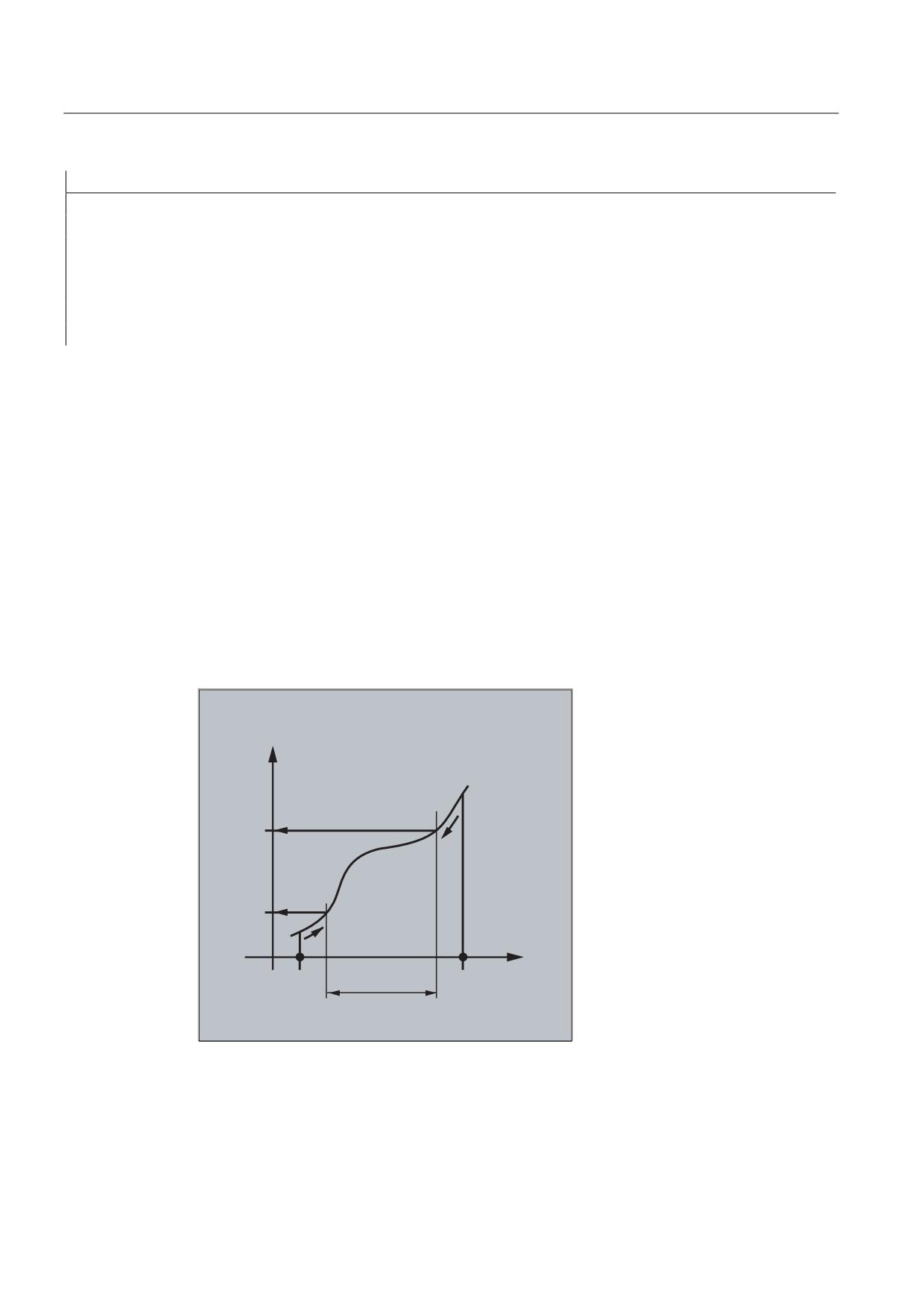
CTAB with non-periodic curve tables
If the specified <master value> is outside the definition range, the upper or lower limit will be
output as the following value:
6ODYH YDOXH
)
)
0DVWHU
/
'HILQLWLRQ UDQJH
/
YDOXH
Job Planning
516
Programming Manual, 03/2010, 6FC5398-2BP20-1BA0
Axis couplings
9.2 Curve tables (CTAB)
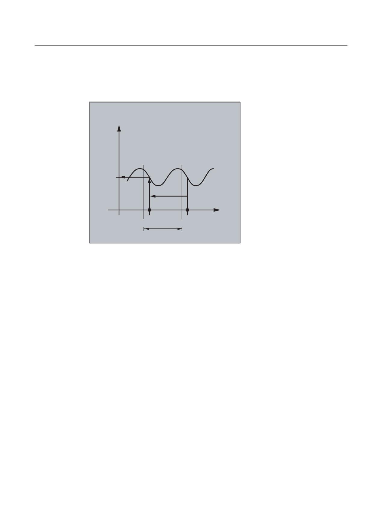
CTAB with periodic curve tables
If the specified <master value> is outside the definition range, the master value is evaluated
modulo of the definition range and the corresponding following value is output:
6ODYH YDOXH
)
0DVWHU
/
'HILQLWLRQ UDQJH
YDOXH
Approximate value for CTABINV
The CTABINV command, therefore, requires an approximate value for the expected master
value. CTABINV returns the master value that is closest to the approximate value. The
approximate value can be, for example, the master value from the previous interpolation
cycle.
Incline of the curve table function
The output of the incline (<gradient>) makes it possible to calculate the velocity of the
leading or following axis at the corresponding position.
Specification of the leading or following axis
The optional specification of the leading and/or following axis is important if the leading and
following axes are configured in different length units.
CTABSSV, CTABSEV
The CTABSSV and CTABSEV commands are not suitable to query programmed segments in the
following cases:
● Circles or involutes are programmed.
● Chamfer or rounding with CHF/ RND is active
● Smoothing with G643 is active
● NC block compression with COMPON/COMPCURV/COMPCAD is active
Job Planning
Programming Manual, 03/2010, 6FC5398-2BP20-1BA0
517
Axis couplings
9.2 Curve tables (CTAB)
9.2.7
Curve tables: Check use of resources (CTABNO, CTABNOMEM, CTABFNO,
CTABSEGID, CTABSEG, CTABFSEG, CTABMSEG, CTABPOLID, CTABPOL,
CTABFPOL, CTABMPOL)
Function
The programmer can use these commands to obtain up-to-date information about the use of
resources for curve tables, table segments, and polynomials.
Syntax
CTABNO
CTABNOMEM(<memory location>)
CTABFNO(<memory location>)
CTABSEGID(<n>,<memory location>)
CTABSEG(<memory location>,<segment type>)
CTABFSEG(<memory location>,<segment type>)
CTABMSEG(<memory location>,<segment type>)
CTABPOLID(<n>)
CTABPOL(<memory location>)
CTABFPOL(<memory location>)
CTABMPOL(<memory location>)
Significance
CTABNO
Determine total number of defined curve tables (in the static and the
dynamic NC memory)
CTABNOMEM
Determine the number of defined curve tables in the specified
<memory location>
CTABFNO
Determine the number of curve tables remaining possible in the
specified <memory location>
CTABSEGID
Determine the number of curve segments of the specified <segment
type> used by curve table number <n>
CTABSEG
Determine the number of curve segments of the specified <segment
type>used in the specified <memory location>
CTABFSEG
Determine the number of curve segments of the specified <segment
type> remaining possible in the specified <memory location>
CTABMSEG
Determine the maximum possible number of curve segments of the
specified <segment type> in the specified <memory location>
CTABPOLID
Determine the number of curve polynomials used by curve table
number <n>
CTABPOL
Determine the number of curve polynomials used in the specified
<memory location>
CTABFPOL
Determine the number of curve polynomials remaining possible in
the specified <memory location>
Job Planning
518
Programming Manual, 03/2010, 6FC5398-2BP20-1BA0
Axis couplings
9.2 Curve tables (CTAB)
CTABMPOL
Determine the maximum possible number of curve polynomials in
the specified <memory location>
<n>
Number (ID) of curve table
<memory location>
Specification of memory location (optional)
"SRAM"
Static NC memory
"DRAM"
Dynamic NC memory
Note:
If a value is not programmed for this parameter, the default memory
location set with
MD20905 $MC_CTAB_DEFAULT_MEMORY_TYPE is used.
<segment type>
Specification of segment type (optional)
"L"
Linear segments
"P"
Polynomial segments
Note:
If no value is programmed for this parameter, the sum of the linear
and polynomial segments is output.
Job Planning
Programming Manual, 03/2010, 6FC5398-2BP20-1BA0
519
Axis couplings
9.3 Axial leading value coupling (LEADON, LEADOF)
9.3
Axial leading value coupling (LEADON, LEADOF)
Note
This function is not available for SINUMERIK 828D!
Function
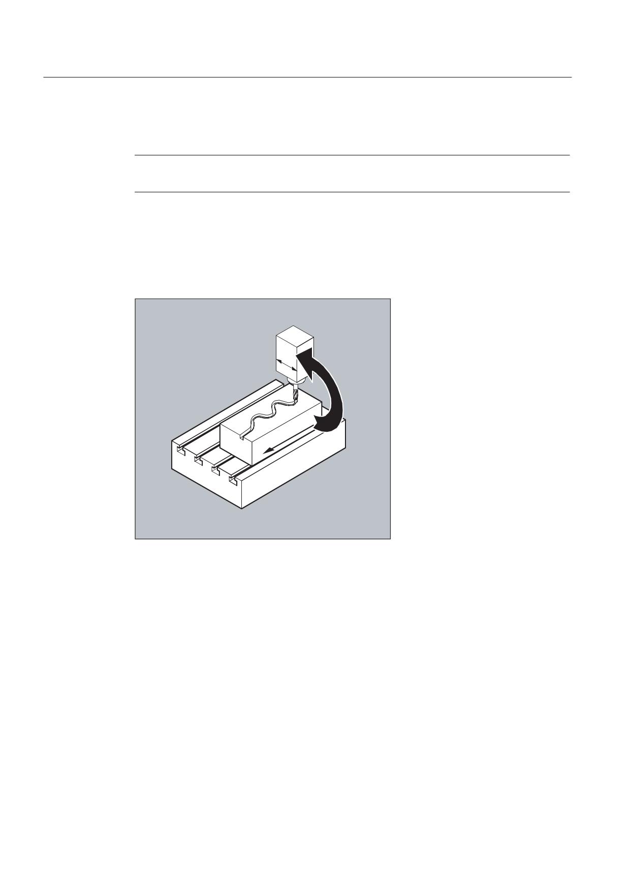
With the axial master value coupling, a leading and a following axis are moved in
synchronism. It is possible to assign the position of the following axis via a curve table or the
resulting polynomial uniquely to a position of the leading axis - simulated if necessary.
<
;
The leading axis is the axis which supplies the input values for the curve table. The following
axis is the axis, which takes the positions calculated by means of the curve table.
Actual value and setpoint coupling
The following can be used as the master value, i.e., as the output values for position
calculation of the following axis:
● Actual values of the leading axis position: Actual value coupling
● Setpoints of the leading axis position: Setpoint value coupling
The master value coupling always applies in the basic coordinate system.
For the creation of curve tables, see section "Curve tables".
For the master value coupling, see /FB/, M3, Coupled-axis motion and master value
coupling.
Job Planning
520
Programming Manual, 03/2010, 6FC5398-2BP20-1BA0
Axis couplings
9.3 Axial leading value coupling (LEADON, LEADOF)
Syntax
LEADON(FAxis,LAxis,n)
LEADOF(FAxis,LAxis)
or deactivation without specifying the leading axis:
LEADOF(FAxis)
The master value coupling can be activated and deactivated both from the part program and
during the movement from synchronized actions, see section "Motion synchronous actions" .
Significance
LEADON
Activate master value coupling
LEADOF
Deactivate master value coupling
Faxis
Following axis
Laxis
Leading axis
n
Curve table number
$SA_LEAD_TYPE
Switching between setpoint and actual value coupling
Deactivate master value coupling, LEADOF
When you deactivate the master value coupling, the following axis becomes a normal
command axis again!
Axial master value coupling and different operating states, RESET
Depending on the setting in the machine data, the master value couplings are deactivated
with RESET.
Example of master value coupling from synchronous action
In a pressing plant, an ordinary mechanical coupling between a leading axis (stanchion
shaft) and axis of a transfer system comprising transfer axes and auxiliary axes is to be
replaced by an electronic coupling system.
It demonstrates how a mechanical transfer system is replaced by an electronic transfer
system. The coupling and decoupling processes are implemented as static synchronized
actions.
From the leading axis LV (stanchion shaft), transfer axes and auxiliary axes are controlled as
following axes that are defined via curve tables.
Following axes
X feed or master value axis
YL closing or transverse axis
ZL lifting axis
U roll feed, auxiliary axis
V guide head, auxiliary axis
W greasing, auxiliary axis
Job Planning
Programming Manual, 03/2010, 6FC5398-2BP20-1BA0
521
Axis couplings
9.3 Axial leading value coupling (LEADON, LEADOF)
Actions
The actions that occur include, for example, the following synchronized actions:
● Activate coupling, LEADON(following axis, leading axis, curve table number)
● Deactivate coupling, LEADOF(following axis, leading axis)
● Set actual value, PRESETON(axis, value)
● Set marker, $AC_MARKER[i]= value
● Coupling type: real/virtual master value
● Approaching axis positions, POS[axis]=value
Conditions
Fast digital inputs, real-time variables $AC_MARKER and position comparisons are linked using
the Boolean operator AND for evaluation as conditions.
Note
In the following example, line change, indentation and bold type are used for the sole
purpose of improving readability of the program. To the control, everything that follows a line
number constitutes a single line.
Comments
Program code
Comments
; Defines all static synchronized actions.
;
****Reset marker
N2 $AC_MARKER[0]=0 $AC_MARKER[1]=0 $AC_MARKER[2]=0 $AC_MARKER[3]=0 $AC_MARKER[4]=0 $AC_MARKER[5]=0
$AC_MARKER[6]=0 $AC_MARKER[7]=0
;
**** E1 0=>1 transfer ON
N10 IDS=1 EVERY ($A_IN[1]==1) AND ($A_IN[16]==1) AND ($AC_MARKER[0]==0)
DO LEADON(X,LW,1) LEADON(YL,LW,2) LEADON(ZL,LW,3) $AC_MARKER[0]=1
;
**** E1 0=>1 coupling roller feed ON
N20 IDS=11 EVERY ($A_IN[1]==1) AND ($A_IN[5]==0) AND ($AC_MARKER[5]==0)
DO LEADON(U,LW,4) PRESETON(U,0) $AC_MARKER[5]=1
;
**** E1 0->1 coupling alignment head ON
N21 IDS=12 EVERY ($A_IN[1]==1) AND ($A_IN[5]==0) AND ($AC_MARKER[6]==0)
DO LEADON(V,LW,4) PRESETON(V,0) $AC_MARKER[6]=1
;
**** E1 0->1 lubrication coupling ON
N22 IDS=13 EVERY ($A_IN[1]==1) AND ($A_IN[5]==0) AND ($AC_MARKER[7]==0)
DO LEADON(W,LW,4) PRESETON(W,0) $AC_MARKER[7]=1
;
**** E2 0=>1 coupling OFF
N30 IDS=3 EVERY ($A_IN[2]==1)
DO LEADOF(X,LW) LEADOF(YL,LW) LEADOF(ZL,LW) LEADOF(U,LW) LEADOF(V,LW) LEADOF(W,LW) $AC_MARKER[0]=0
$AC_MARKER[1]=0 $AC_MARKER[3]=0 $AC_MARKER[4]=0 $AC_MARKER[5]=0 $AC_MARKER[6]=0 $AC_MARKER[7]=0
N110 G04 F01
N120 M30
Job Planning
522
Programming Manual, 03/2010, 6FC5398-2BP20-1BA0
Axis couplings
9.3 Axial leading value coupling (LEADON, LEADOF)
Description
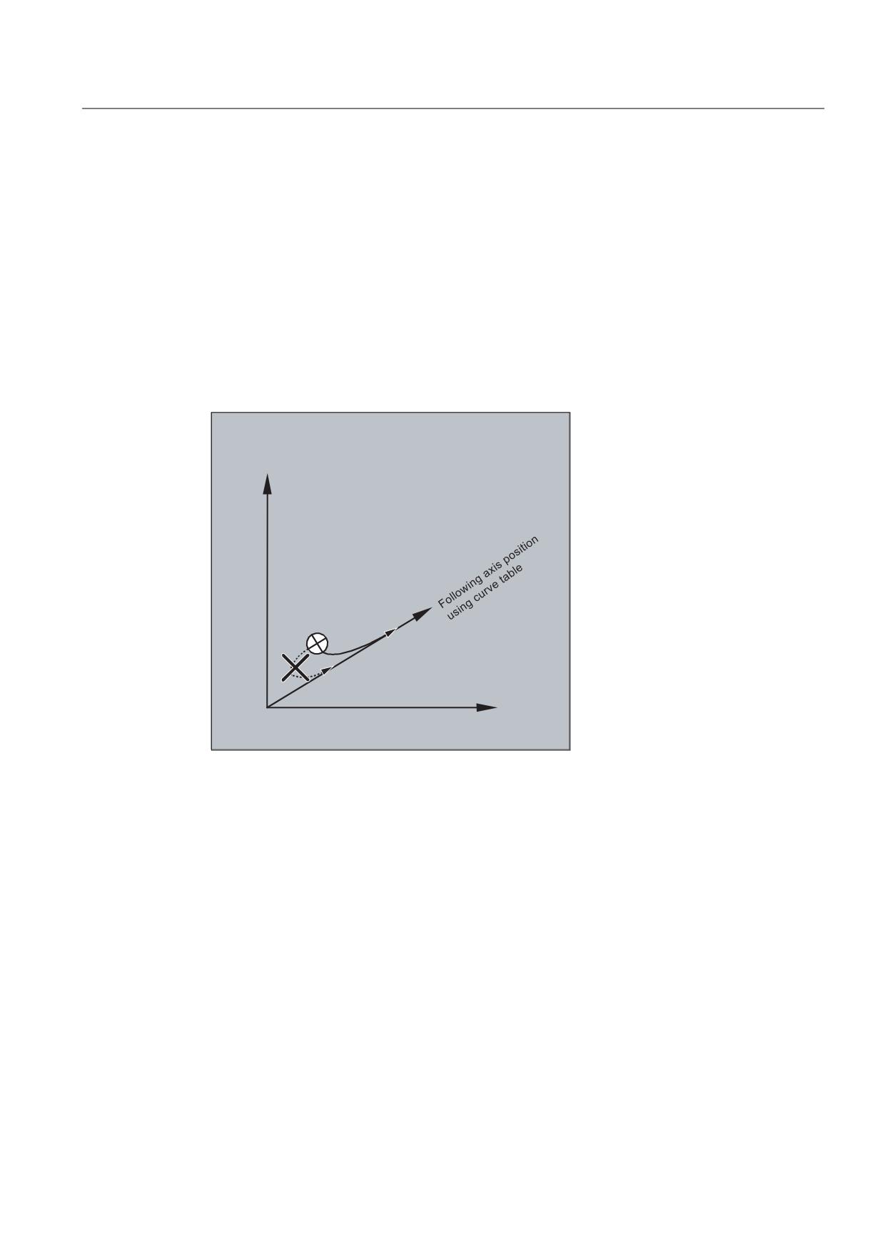
Master value coupling requires synchronization of the leading and the following axes. This
synchronization can only be achieved if the following axis is inside the tolerance range of the
curve definition calculated from the curve table when the master value coupling is activated.
The tolerance range for the position of the following axis is defined via machine data MD
37200: COUPLE_POS_POL_COARSE A_LEAD_TYPE.
If the following axis is not yet at the correct position when the master value coupling is
activated, the synchronization run is automatically initiated as soon as the position setpoint
value calculated for the following axis is approximately the real following axis position. During
the synchronization procedure the following axis is traversed in the direction that is defined
by the setpoint speed of the following axis (calculated from master spindle and using the
CTAB curve table).
<
)ROORZLQJ D[LV SRVLWLRQ
<
No synchronism
If the following axis position calculated moves away from the current following axis position
when the master value coupling is activated, it is not possible to establish synchronization.
Job Planning
Programming Manual, 03/2010, 6FC5398-2BP20-1BA0
523
Axis couplings
9.3 Axial leading value coupling (LEADON, LEADOF)
Actual value and setpoint coupling
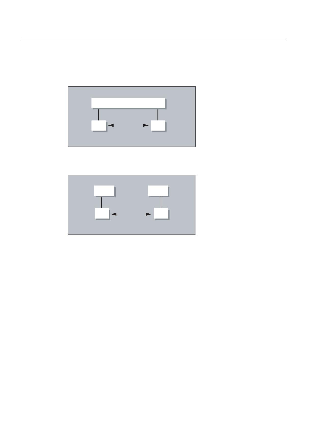
Setpoint coupling provides better synchronization of the leading and following axis than
actual value coupling and is therefore set by default.
1&8
6HWSRLQW YDOXH FRXSOLQJ
$[
$[
$FWXDO YDOXH FRXSOLQJ
Setpoint coupling is only possible if the leading and following axis are interpolated by the
same NCU. With an external leading axis, the following axis can only be coupled to the
leading axis via the actual values.
1&8
1&8
$[
$[
$FWXDO YDOXH FRXSOLQJ
A switchover can be programmed via setting data $SA_LEAD_TYPE
You must always switch between the actual-value and setpoint coupling when the following
axis stops. It is only possible to resynchronize after switchover when the axis is motionless.
Application example
You cannot read the actual values without error during large machine vibrations. If you use
master value coupling in press transfer, it might be necessary to switchover from actual-
value coupling to setpoint coupling in the work steps with the greatest vibrations.
Job Planning
524
Programming Manual, 03/2010, 6FC5398-2BP20-1BA0
Axis couplings
9.3 Axial leading value coupling (LEADON, LEADOF)
Master value simulation with setpoint coupling
Via machine data, you can disconnect the interpolator for the leading axis from the servo. In
this way you can generate setpoints for setpoint coupling without actually moving the leading
axis.
Master values generated from a setpoint link can be read from the following variables so that
they can be used, for example, in synchronized actions:
- $AA_LEAD_P
Master value position
- $AA_LEAD_V
Master value velocity
Create master value
As an option, master values can be generated with other self-programmed methods. The
master values generated in this way are written to and read from variables
- $AA_LEAD_SP
Master value position
- $AA_LEAD_SV
Master value velocity
Before you use these variables, the setting data $SA_LEAD_TYPE = 2 must be set.
Status of coupling
You can query the status of the coupling in the NC program with the following system
variable:
$AA_COUP_ACT[[axis]]
0: No coupling active
16: Master value coupling active
Status management for synchronized actions
Switching and coupling events are managed via real-time variables:
$AC_MARKER[i] = n
managed with:
i flag number
n status value
Job Planning
Programming Manual, 03/2010, 6FC5398-2BP20-1BA0
525
Axis couplings
9.4 Electronic gear (EG)
9.4
Electronic gear (EG)
Function
The "Electronic gear" function allows you to control the movement of a following axis
according to linear traversing block as a function of up to five leading axes. The relationship
between each leading axis and the following axis is defined by the coupling factor.
The following axis motion part is calculated by an addition of the individual leading axis
motion parts multiplied by their respective coupling factors. When an EG axis grouping is
activated, it is possible to synchronize the following axes in relation to a defined position. A
gear group can be:
● defined,
● activated,
● deactivated,
● deleted.
The following axis movement can be optionally derived from
● Setpoints of the leading axes, as well as
● Actual values of leading axes.
Non-linear relationships between each leading axis and the following axis can also be
realized as extension using curve tables (see "Path traversing behavior" section). Electronic
gears can be cascaded, i.e., the following axis of an electronic gear can be the leading axis
for a further electronic gear.
9.4.1
Defining an electronic gear (EGDEF)
Function
An EG axis group is defined by specifying the following axis and at least one, however not
more than five, leading axis, each with the relevant coupling type.
Requirements
Prerequisites for defining an EG axis group:
It is not permissible to define an axis coupling for the following axis (or an existing one must
first be deleted with EGDEL).
Syntax
EGDEF(following axis,leading axis1,coupling type1,leading
axis2,coupling type2,...)
Job Planning
526
Programming Manual, 03/2010, 6FC5398-2BP20-1BA0
Axis couplings
9.4 Electronic gear (EG)
Significance
EGDEF
Definition of an electronic gear
Following axis
Axis that is influenced by the leading axes
Leading axis1
,...,
Axes that influence the following axis
Leading axis5
Coupling type1
,...,
Coupling type
Coupling type5
The coupling type does not need to be the same for all leading
axes and must be programmed separately for each individual
master.
Value:
Significance:
0
The following axis is influenced by the actual value of
the corresponding leading axis.
1
The following axis is influenced by the setpoint of the
corresponding leading axis.
Note
The coupling factors are preset to zero when the EG axis grouping is defined.
Note
EGDEF triggers preprocessing stop. The gearbox definition with EGDEF should also be used
unaltered if, for systems, one or more leading axes affect the following axis via a curve table.
Example
Program code
Comments
EGDEF(C,B,1,Z,1,Y,1)
; Definition of an EG axis group. Leading axes B, Z, Y
influence the following axis C via the setpoint.
Job Planning
Programming Manual, 03/2010, 6FC5398-2BP20-1BA0
527
Axis couplings
9.4 Electronic gear (EG)
9.4.2
Switch-in the electronic gearbox (EGON, EGONSYN, EGONSYNE)
Function
There are 3 ways to switch-in an EG axis group.
Syntax
Variant 1:
The EG axis group is selectively switched-in without synchronization with:
EGON(FA,"block change mode",LA1,Z1,N1,LA2,Z2,N2,...,LA5,Z5,N5)
Variant 2:
The EG axis group is selectively activated with synchronization with:
EGONSYN(FA,"block change mode",SynPosFA,[,LAi,SynPosLAi,Zi,Ni])
Variant 3:
The EG axis group is selectively switched-in with synchronization and the approach mode
specified with:
EGONSYNE(FA,"block change mode",SynPosFA,approach
mode[,LAi,SynPosLAi,Zi,Ni])
Significance
Version 1:
FA
Following axis
Block change mode
The following modes can be used:
"NOC"
Block change takes place immediately
"FINE"
Block change is performed in "Fine
synchronism"
"COARSE"
Block change is performed in "Coarse
synchronism"
"IPOSTOP"
Block change is performed for setpoint-
based synchronism
LA1, ... LA5
Leading axes
Z1, ... Z5
Counter for coupling factor i
N1, ... N5
Denominator for coupling factor i
Coupling factor i = Counter i / Denominator i
Only the leading axes previously specified with the EGDEF command may be programmed in
the activation line. At least one leading axis must be programmed.
Job Planning
528
Programming Manual, 03/2010, 6FC5398-2BP20-1BA0
Axis couplings
9.4 Electronic gear (EG)
Version 2:
FA
Following axis
Block change mode
The following modes can be used:
"NOC"
Block change takes place immediately
"FINE"
Block change is performed in "Fine
synchronism"
"COARSE"
Block change is performed in "Coarse
synchronism"
"IPOSTOP"
Block change is performed for
setpoint-based synchronism
[,LAi,SynPosLAi,Zi,Ni]
(do not write the square brackets)
Min. 1, max. 5 sequences of:
LA1, ... LA5
Leading axes
SynPosLAi
Synchronized position for i-th leading axis
Z1, ... Z5
Numerator for coupling factor i
N1, ... N5
Denominator for coupling factor i
Coupling factor i = numerator i/denominator i
Only leading axes previously specified with the EGDEF command may be programmed in the
activation line. Through the programmed "Synchronized positions" for the following axis
(SynPosFA) and for the leading axes (SynPosLA), positions are defined for which the axis
grouping is interpreted as synchronous. If the electronic gear is not in the synchronized state
when the grouping is switched on, the following axis traverses to its defined synchronized
position.
Version 3:
The parameters correspond to those of version 2 plus:
Approach mode
The following modes can be used:
"NTGT"
Approach next tooth gap time-optimized
"NTGP"
Approach next tooth gap path-optimized
"ACN"
Traverse rotary axis in negative direction absolute
"ACP"
Traverse rotary axis in positive direction absolute
"DCT"
Time-optimized for programmed synchronous position
"DCP"
Distance-optimized to the programmed synchronous
position
Variant 3 only affects modulo following axes that are coupled to modulo leading axes. Time
optimization takes account of velocity limits of the following axis.
Job Planning
Programming Manual, 03/2010, 6FC5398-2BP20-1BA0
529
Axis couplings
9.4 Electronic gear (EG)
Further Information
Description of the switch-in versions
Version 1:
The positions of the leading axes and following axis at the instant the grouping is switched
on are stored as "Synchronized positions". The "Synchronized positions" can be read with
the system variable $AA_EG_SYN.
Version 2:
If modulo axes are contained in the coupling group, their position values are modulus-
reduced. This ensures that the next possible synchronized position is approached (so-called
relative synchronization: e.g. the next tooth gap). The synchronized position is only
approached if "Enable following axis override" interface signal DB(30 + axis number), DBX
26 bit 4 is issued for the following axis. If it is not issued, the program stops at the
EGONSYN block and self-clearing alarm 16771 is output until the above mentioned signal is
set.
Version 3:
The tooth distance (deg.) is calculated like this: 360 * Zi/Ni. If the following axis is stopped at
the time of calling, path optimization returns responds identically to time optimization.
If the following axis is already in motion, NTGP will synchronize at the next tooth gap
irrespective of the current velocity of the following axis. If the following axis is already in
motion, NTGT will synchronize at the next tooth gap depending on the current velocity of the
following axis. The axis is also decelerated, if necessary.
Curve tables
If a curve table is used for one of the leading axes:
Ni
The denominator of the coupling factor for linear coupling must be set to 0.
(Denominator 0 would be illegal for linear couplings.) Denominator zero tells the
control that
Zi
is the number of the curve table to use. The curve table with the specified
number must already be defined at POWER ON.
LAi
The leading axis specified corresponds to the one specified for coupling via
coupling factor (linear coupling).
For more information about using curve tables and cascading and synchronizing electronic
gears, please refer to:
References:
Function Manual Special Functions; Coupled Axes and ESR (M3), "Coupled Motion and
Leading Value Coupling".
Job Planning
530
Programming Manual, 03/2010, 6FC5398-2BP20-1BA0
Axis couplings
9.4 Electronic gear (EG)
Response of the Electronic gear at Power ON, RESET, mode change, block search
● No coupling is active after POWER ON.
● The status of active couplings is not affected by RESET or operating mode switchover.
● During block searches, commands for switching, deleting and defining the electronic gear
are not executed or collected, but skipped.
System variables of the electronic gear
By means of the electronic gear's system variables, the part program can determine the
current states of an EG axis grouping and react to them if required.
The system variables of the electronic gearbox are designated as follows:
$AA_EG_ ...
or
$VA_EG_ ...
References:
System Variables Manual
9.4.3
Switching-in the electronic gearbox (EGOFS, EGOFC)
Function
There are 3 different ways to switch-out an active EG axis group.
Programming
Version 1:
Syntax
Description
EGOFS(following axis)
The electronic gear is deactivated. The following axis is
braked to a standstill. This call triggers a preprocessing
stop.
Version 2:
Syntax
Description
EGOFS(following axis,leading axis1,…,leading axis5) This command parameter
setting made it possible to
selectively remove the influence
of the individual leading axes on
the following axis' motion.
Job Planning
Programming Manual, 03/2010, 6FC5398-2BP20-1BA0
531
Axis couplings
9.4 Electronic gear (EG)
At least one leading axis must be specified. The influence of the specified leading axes on
the slave is selectively inhibited. This call triggers a preprocessing stop. If the call still
includes active leading axes, then the slave continues to operate under their influence. If the
influence of all leading axes is excluded by this method, then the following axis is braked to a
standstill.
Version 3:
Syntax
Description
EGOFC(following spindle1)
The electronic gear is deactivated. The following spindle
continues to traverse at the speed/velocity that applied at
the instant of deactivation. This call triggers a preprocessing
stop.
Note
This version is only permitted for spindles.
9.4.4
Deleting the definition of an electronic gear (EGDEL)
Function
An EG axis group must be switched-out before its definition can be deleted.
Programming
Syntax
Significance
EGDEL(following axis)
The coupling definition of the axis group is deleted. Additional
axis groups can be defined by means of EGDEF until the
maximum number of simultaneously activated axis groups is
reached. This call triggers a preprocessing stop.
Job Planning
532
Programming Manual, 03/2010, 6FC5398-2BP20-1BA0
Axis couplings
9.4 Electronic gear (EG)
9.4.5
Rotational feedrate (G95) / electronic gear (FPR)
Function
The FPR command can be used to specify the following axis of an electronic gear as the axis,
which determines the revolutional feedrate. Please note the following with respect to this
command:
● The feedrate is determined by the setpoint velocity of the following axis of the electronic
gear.
● The setpoint velocity is calculated from the speeds of the leading spindles and modulo
axes (which are not path axes) and from their associated coupling factors.
● Speed parts of linear or non-modulo leading axes and overlaid movement of the following
axis are not taken into account.
Job Planning
Programming Manual, 03/2010, 6FC5398-2BP20-1BA0
533
Axis couplings
9.5 Synchronous spindle
9.5
Synchronous spindle
Function
Synchronous operation involves a following spindle (FS) and a leading spindle (LS), referred
to as the synchronous spindle pair. The following spindle imitates the movements of the
leading spindle when a coupling is active (synchronous operation) in accordance with the
defined functional interrelationship.
The synchronous spindle pairs for each machine can be assigned a fixed configuration by
means of channel-specific machine data or defined for specific applications via the CNC
parts program. Up to two synchronized spindle pairs can be operated simultaneously on
each NC channel.
Refer to the parts program for the following coupling actions
● defined or changed
● activated
● deactivated
● deleted
from the parts program.
In addition, depending on the software status
● it is possible to wait for the synchronism conditions
● the block change method can be changed
● either the setpoint coupling or actual value coupling type is selected or the angular offset
between master and following spindle specified
● when activating the coupling, previous programming of the following axis is transferred
● either a measured or a known synchronism variance is corrected.
Job Planning
534
Programming Manual, 03/2010, 6FC5398-2BP20-1BA0
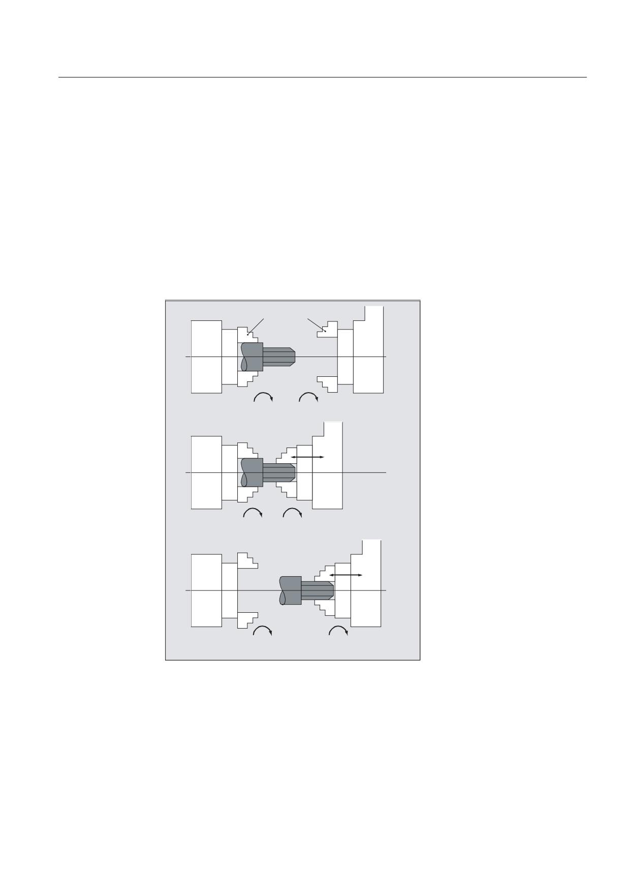
Axis couplings
9.5 Synchronous spindle
9.5.1
Synchronous spindle: Programming (COUPDEF, COUPDEL, COUPON,
COUPONC, COUPOF, COUPOFS, COUPRES, WAITC)
Function
The synchronous spindle function facilitates synchronous traversing of two spindles
(following spindle FS and leading spindle LS), e.g. for workpiece transfer on-the-fly.
The function supports the following modes:
● Speed synchronism (nFS = n LS)
● position synchronism (ϕFS = ϕLS)
● position synchronism with angular offset (ϕFS = ϕLS+ ∆ϕ)
&KXFNV
Q
Q
6SLQGOH
6SLQGOH
Q
Q
6SLQGOH
6SLQGOH
Q
Q
6SLQGOH
6SLQGOH
Job Planning
Programming Manual, 03/2010, 6FC5398-2BP20-1BA0
535

Axis couplings
9.5 Synchronous spindle
Multi-edge machining can even be supported by means of the specification of a
transformation ratio not equal to 1 between the leading and following spindles.
Q
Q
Syntax
COUPDEF(<FS>,<LS>,<TFS>,<TLS>,<block change>,<coupling type>)
COUPON(<FS>,<LS>,<POSFS>)
COUPONC(<FS>,<LS>)
COUPOF(<FS>,<LS>,<POSFS>,<POSLS>)
COUPOFS(<FS>,<LS>)
COUPOFS(<FS>,<LS>,<POSFS>)
COUPRES(<FS>,<LS>)
COUPDEL(<FS>,<LS>)
WAITC(<FS>,<block change>,<LS>,<block change>)
Note
Abbreviated notation
The COUPOF, COUPOFS, COUPRES, and COUPDEL statements support abbreviated notation without
specification of the leading spindle.
Meaning
COUPDEF:
Define/change coupling on user-specific basis
COUPON:
Activate coupling. The following spindle synchronizes to the leading
spindle based on the actual speed
COUPONC:
Coupling when activating with previous programming of M3 S... or
M4 S
A difference in speed for the following spindle is transferred
immediately.
COUPOF:
Deactivate coupling.
• With immediate block change:
COUPOF(<S2>,<S1>)
• Block change only after <POSFS> or <POSLS> deactivation
position(s) has (have) been crossed:
COUPOF(<S2>,<S1>,<POSFS>)
COUPOF(<S2>,<S1>,<POSFS>,<POSLS>)
Job Planning
536
Programming Manual, 03/2010, 6FC5398-2BP20-1BA0
Axis couplings
9.5 Synchronous spindle
COUPOFS:
Deactivating a coupling with stop of following spindle.
Block change as quickly as possible with immediate block change:
COUPOFS(<S2>,<S1>)
Block change only after passing the switch-off position:
COUPOFS(<S2>,<S1>,<POSFS>)
COUPRES:
Reset coupling parameters to configured MD and SD
COUPDEL:
Delete user-defined coupling
WAITC:
Wait for synchronized run condition
(NOC are increased to IPO during block changes)
<FS>:
Designation of following spindle
Optional parameters:
<LS>:
Designation of main spindle
Specification with spindle number: e.g. S2, S1
<TFS>, <TLS>:
Transformation ratio between FS and LS.
<TFS> = numerator, <TLS> = denominator
Default: <TFS> / <TLS> = 1.0 ; specification of denominator optional
<block change>
:
Block change behavior
The block change is:
"NOC"
Immediately
"FINE"
On reaching "Synchronism fine"
"COARSE"
On reaching "Synchronism coarse"
"IPOSTOP"
On reaching IPOSTOP; in other words, after
setpoint-based synchronism (default)
The block change behavior is effective modally.
:
Coupling type: Coupling between FS and LS
<coupling type>
"DV"
Setpoint linkage (default)
"AV"
Actual value coupling
"VV"
Speed coupling
The coupling type is modal.
<POSFS>:
Angle offset between leading and following spindles
Range of values:
0°… 359.999°
<POSFS>,<POSLS>
:
Switch-off positions of the following and leading spindles
"The block change is enabled once POSFS, POSLS has been
passed"
Range of values:
0°… 359.999°
Job Planning
Programming Manual, 03/2010, 6FC5398-2BP20-1BA0
537
Axis couplings
9.5 Synchronous spindle
Examples
Example 1: Machining with leading and following spindles
Programming
Comment
; Leading spindle = master spindle = spindle 1
; Following spindle = spindle 2
N05 M3 S3000 M2=4 S2=500
; Leading spindle rotates at 3000 rpm,
following spindle at 500 rpm.
N10 COUPDEF(S2,S1,1,1,"NOC","Dv")
; Definition of the coupling (can also be configured).
N70 SPCON
; Bring leading spindle into closed-loop position control
(setpoint coupling).
N75 SPCON(2)
; Bring following spindle into closed-loop position control.
N80 COUPON(S2,S1,45)
; On-the-fly coupling to offset position = 45 degrees.
N200 FA[S2]=100
; Positioning speed = 100 degrees/min
N205 SPOS[2]=IC(-90)
; Traverse with 90 degree overlay in negative direction.
N210 WAITC(S2,"Fine")
; Wait for "fine" synchronism.
N212 G1 X... Y... F...
; Machining
N215 SPOS[2]=IC(180)
; Traverse with 180 degree overlay in the positive
direction.
N220 G4 S50
; Dwell time = 50 revolutions of the master spindle
N225 FA[S2]=0
; Activate configured velocity (MD).
N230 SPOS[2]=IC(-7200)
;
20 revolutions. Move with configured velocity in the
negative direction.
N350 COUPOF(S2,S1)
; Couple-out on-the-fly, S=S2=3000
N355 SPOSA[2]=0
; Stop FS at zero degrees.
N360 G0 X0 Y0
N365 WAITS(2)
; Wait for spindle 2.
N370 M5
; Stop FS.
N375 M30
Job Planning
538
Programming Manual, 03/2010, 6FC5398-2BP20-1BA0
Axis couplings
9.5 Synchronous spindle
Example 2: Programming a difference in speed
Programming
Comment
; Leading spindle = master spindle = spindle 1
; Following spindle = spindle 2
N01 M3 S500
; Leading spindle rotates at 500 rpm.
N02 M2=3 S2=300
; Following spindle rotates at 300 rpm.
N10 G4 F1
; Dwell time of master spindle.
N15 COUPDEF (S2,S1,-1)
; Coupling factor with ratio -1:1
N20 COUPON (S2,S1)
; Activate coupling. The speed of the following spindle results from
the speed of the leading spindle and coupling factor.
N26 M2=3 S2=100
; Programming a difference in speed.
Example 3: Examples of transfer of a movement for difference in speed
1. Activate coupling during previous programming of following spindle with COUPON
Programming
Comment
; Leading spindle = master spindle = spindle 1
; Following spindle = spindle 2
N05 M3 S100 M2=3 S2=200
; Leading spindle rotates at 100 rpm, following spindle at 200 rpm.
N10 G4 F5
; Dwell time = 5 seconds of master spindle
N15 COUPDEF(S2,S1,1)
; Transformation ratio of FS to LS is 1.0 (default).
N20 COUPON(S2,S1)
; On-the-fly coupling to the leading spindle.
N10 G4 F5
; Following spindle rotates at 100 rpm.
2. Activate coupling during previous programming of following spindle with COUPONC
Programming
Comment
; Leading spindle = master spindle = spindle 1
; Following spindle = spindle 2
N05 M3 S100 M2=3 S2=200
; Leading spindle rotates at 100 rpm, following spindle at 200 rpm.
N10 G4 F5
; Dwell time = 5 seconds of master spindle
N15 COUPDEF(S2,S1,1)
; Transformation ratio of FS to LS is 1.0 (default).
N20 COUPONC(S2,S1)
; On-the-fly coupling to leading spindle and transfer previous speed
to S2.
N10 G4 F5
; S2 rotates at 100 rpm + 200 rpm = 300 rpm
Job Planning
Programming Manual, 03/2010, 6FC5398-2BP20-1BA0
539

Axis couplings
9.5 Synchronous spindle
3. Activate coupling with following spindle stationary with COUPON
Programming
Comment
; Leading spindle = master spindle = spindle 1
; Following spindle = spindle 2
N05 SPOS=10 SPOS[2]=20
; Following spindle S2 in positioning mode.
N15 COUPDEF(S2,S1,1)
; Transformation ratio of FS to LS is 1.0 (default).
N20 COUPON(S2,S1)
; On-the-fly coupling to the leading spindle.
N10 G4 F1
; Coupling is closed, S2 stops at 20 degrees.
4. Activate coupling with following spindle stationary with COUPONC
Note
Positioning or axis mode
If the following spindle is in positioning or axis mode before coupling, then the following
spindle behaves the same for COUPON(<FS>,<LS>) and COUPONC(<FS>,<LS>).
NOTICE
Leading spindle and axis operation
If, prior to the coupling being defined, the leading spindle is in axis operation, the velocity
limit value from machine data
MD32000 $MA_MAX_AX_VELO (maximum axis velocity) will still apply even after the
coupling is activated.
To avoid this behavior, the axis must be switched to spindle mode (M3 S... or M4 S...) prior
to the coupling being defined.
Further information
Define synchronized spindle pair
Configured coupling:
For the configured coupling, the leading and following spindles are defined in machine data.
The configured spindles cannot be changed in the part program. The coupling can be
parameterized in the part program using COUPDEF (on condition that no write protection is
valid).
User-defined coupling:
COUPDEF can be used to redefine or change a coupling in the part program. If a coupling is
already active, it has to be deleted first with COUPDEL before a new coupling is defined.
Define coupling: COUPDEF
A coupling is defined in its entirety by:
COUPDEF(<FS>,<LS>,<TFS>,<TLS>, block change behavior, coupling type)
Job Planning
540
Programming Manual, 03/2010, 6FC5398-2BP20-1BA0
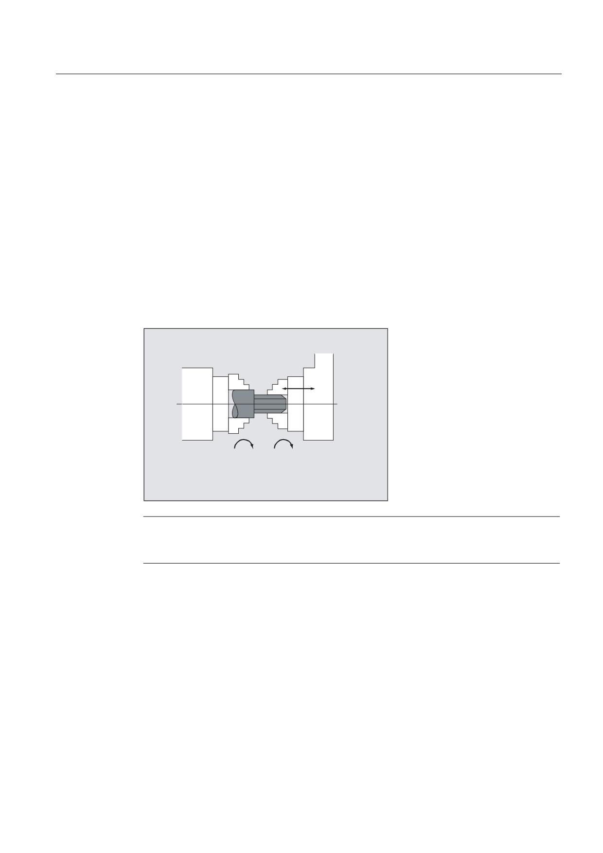
Axis couplings
9.5 Synchronous spindle
Following spindle (FS) and leading spindle (LS)
The coupling is uniquely defined using the axis names for the following spindle (FS) and the
leading spindle (LS). The axis names have to be programmed with every COUPDEF operation.
The other coupling parameters are modal and only have to be programmed if they change.
Example:
COUPDEF(S2,S1)
Transformation ratio, TFS / TLS
The transformation ratio is specified as a speed ratio between the following spindle
(numerator) and the leading spindle (denominator). The numerator must be programmed. In
the absence of a programmed value, the denominator is set to = 1.0.
Example:
Following spindle S2 and leading spindle S1, transformation ratio = 1 / 4 = 0.25.
COUPDEF(S2,S1,1.0, 4.0)
Q
Q
6SLQGOH
6SLQGOH
/HDG
)ROORZLQJ
VSLQGOH
VSLQGOH
Note
The transformation ratio can also be changed on-the-fly (when the coupling is active and the
spindles are rotating).
Block change behavior NOC, FINE, COARSE, IPOSTOP
The following abbreviated notation can be used when programming the block change
behavior:
● "NO": Immediately (default)
● "FI": On reaching "Synchronism fine"
● "CO": On reaching "Synchronism coarse"
● "IP": On reaching IPOSTOP; in other words, after setpoint-based synchronism
Job Planning
Programming Manual, 03/2010, 6FC5398-2BP20-1BA0
541

Axis couplings
9.5 Synchronous spindle
Type of coupling DV, AV
CAUTION
The coupling type may be changed only when the coupling is deactivated!
Activate synchronized mode COUPON, POSFS
● Activation of coupling with any angle reference between LS and FS:
- COUPON(S2,S1)
- COUPON(S2,S1,<POSFS>)
- COUPON(S2)
● Activation of coupling with angular offset <POSFS>
Position-synchronized coupling for profiled workpieces.
<POSFS>refers to the 0° position of the lead spindle in the positive direction of rotation
<POSFS> value range: 0°… 359.999°
- COUPON(S2,S1,30)
You can use this method to change the angle offset even when the coupling is already
active.
Position the following spindle
When the synchronized spindle coupling is active, following spindles can also be positioned
within the ±180° range independently of the motion initiated by the master spindle.
Positioning SPOS
The following spindle can be interpolated with SPOS=….
Example:
SPOS[2]=IC(-90)
Further information about SPOS appears in:
Reference:
Programming Manual, Basics
Difference in speed M3 S... or M4 S...
A difference in speed results from signed superimposition of two sources of speed and is
programmed again for the following spindle e.g. with S<n>=... or M<n>=3, M<n>=4 in the speed
control mode during an active synchronized spindle coupling. During the process, this speed
component is derived from the main spindle using the coupling factor and the following
spindle added to this with the correct prefix.
Note
When the direction of rotation is M3 or M4, the speed S... also has to be reprogrammed
because otherwise an alarm is triggered to report missing programming.
For more information about the speed difference, please refer to:
Reference:
Function Manual, Extended Functions; Synchronous Spindle (S3).
Job Planning
542
Programming Manual, 03/2010, 6FC5398-2BP20-1BA0
Axis couplings
9.5 Synchronous spindle
Difference in speed for COUPONC
Transfer of a movement for difference in speed
When a synchronous spindle coupling is activated with COUPONC a currently active speed is
overlaid on the following spindle (M3 S... or M4 S...).
Note
Enabling overlaying
Overlay of a spindle speed ( M3 S... or M4 S...) using a synchronous spindle coupling
COUPONC only becomes effective if the overlay has been enabled.
Dynamic restriction of the leading spindle
The dynamic responses of the leading spindle have to be restricted to such an extent that
when overlaying is applied to the following spindle, its dynamics limit values are not
exceeded.
Velocity, acceleration: FA, ACC, OVRA, VELOLIMA
Axial velocity and acceleration of a following spindle can be programmed with:
● FA[SPI(S<n>)] or FA[S<n>] (axial velocity)
● ACC[SPI(S<n>)] or ACC[S<n>] (axial acceleration)
● OVRA[SPI(S<n>)] and OVRA[S<n>] (axial override)
● VELOLIMA[SPI(S<n>)] and VELOLIMA[S<n>] (increase and reduction of axial velocity
respectively)
When <n> = 1, 2, 3, ... (spindle numbers of the following spindles)
Reference:
Programming Manual Fundamentals
Note
Acceleration component JERKLIMA[S<n>]
Programming an increase or reduction in axial velocity is currently ineffective for spindles.
Further information about configuring the axial dynamic response is provided in:
Reference:
Function Manual Extended Functions; Rotary Axes (R2)
Programmable block change behavior WAITC
WAITC can be used to define block change behavior, for example after a change to coupling
parameters or positioning actions, with a variety of synchronism conditions (coarse, fine,
IPOSTOP). If no synchronism conditions are specified, the block change behavior specified in
the COUPDEF definition will apply.
Example:
Wait for synchronism condition according to COUPDEF to be fulfilled
WAITC( )
Wait for synchronism condition FINE to be fulfilled for following spindle S2 and COARSE to be
fulfilled for following spindle S4:
WAITC(S2,"FINE",S4,"COARSE")
Job Planning
Programming Manual, 03/2010, 6FC5398-2BP20-1BA0
543