SINUMERIK 840D sl/828D. Job Planning. Programming Manual (2010-2018) - page 11

Programming cycles externally
20.1 Technology cycles
Note
If certain transfer parameters (e.g. <_VARI>, <_GMODE>, <_DMODE>, <_AMODE>) have
been indirectly programmed as parameters, the screen form is opened on recompiling but it
cannot be stored as there is no unambiguous assignment to defined selection fields.
20.1.2
Technology-specific overview
The following overview table lists all available externally programmable technology cycles and
the technology assigned to each of them:
Technology
Technology cycle
Drilling
● CYCLE81 - drilling, centering (Page 736)
● CYCLE82 - drilling, counterboring (Page 737)
● CYCLE85 - reaming (Page 746)
● CYCLE86 - boring (Page 747)
● CYCLE83 - deep-hole drilling 1 (Page 740)
● CYCLE830 - deep-hole drilling 2 (Page 772)
● CYCLE84 - tapping without compensating chuck (Page 743)
● CYCLE840 - tapping with compensating chuck (Page 781)
● CYCLE78 - Drill thread milling (Page 732)
● CYCLE802 - arbitrary positions (Page 770)
● HOLES1 - row position pattern (Page 698)
● CYCLE801 - grid or frame position pattern (Page 768)
● HOLES2 - circle or pitch circle position pattern (Page 698)
Turning
● CYCLE951 - stock removal (Page 792)
● CYCLE930 - groove (Page 787)
● CYCLE940 - undercut form E and F / undercut thread
(Page 789)
● CYCLE99 - thread turning (Page 756)
● CYCLE98 - thread chain (Page 752)
● CYCLE92 - cut-off (Page 748)
Contour turning
● CYCLE62 - contour call (Page 717)
● CYCLE952 - stock removal / residual stock removal / plunge
cutting / residual plunge cutting / plunge turning / residual plunge
turning (Page 795)
Job Planning
696
Programming Manual, 12/2018, A5E40869460B AB
Programming cycles externally
20.1 Technology cycles
Technology
Technology cycle
Milling
●
CYCLE61 - Face milling (Page 715)
●
POCKET3 - rectangular pocket (Page 700)
●
POCKET4 - circular pocket (Page 703)
●
CYCLE76 - rectangular spigot (Page 728)
●
CYCLE77 - circular spigot (Page 730)
●
CYCLE79 - multi-edge (Page 734)
●
SLOT1 - longitudinal slot (Page 705)
●
SLOT2 - circumferential slot (Page 708)
●
CYCLE899 - open slot (Page 784)
●
LONGHOLE - elongated hole (Page 710)
●
CYCLE70 - thread milling (Page 722)
●
CYCLE60 - engraving (Page 712)
Contour milling
●
CYCLE62 - contour call (Page 717)
●
CYCLE72 - Path milling (Page 724)
●
CYCLE63 - contour pocket milling / contour pocket residual
material / contour spigot milling / contour spigot residual
material (Page 718)
●
CYCLE64 - Predrilling contour pocket (Page 720)
Grinding
●
CYCLE495 - form-truing (Page 761)
●
CYCLE435 - Set dresser coordinate system (Page 761)
●
CYCLE4071 - longitudinal grinding with infeed at the reversal
point (Page 801)
●
CYCLE4072 - longitudinal grinding with infeed at the reversal
point and cancel signal (Page 802)
●
CYCLE4073 - longitudinal grinding with continuous infeed
(Page 806)
●
CYCLE4074 - longitudinal grinding with continuous infeed and
cancel signal (Page 807)
●
CYCLE4075 - surface grinding with infeed at the reversal point
(Page 810)
●
CYCLE4077 - surface grinding with infeed at the reversal point
and cancel signal (Page 813)
●
CYCLE4078 - surface grinding with continuous infeed
(Page 816)
●
CYCLE4079 - surface grinding with intermittent infeed
(Page 818)
Other
●
CYCLE782 - adjust to load (Page 763)
●
CYCLE800 - swivel plane / swivel tool / align tool (Page 765)
●
CYCLE832 - High-Speed Settings (Page 778)
All
●
GROUP_BEGIN - beginning of program block (Page 820)
●
GROUP_END - end of program block (Page 821)
●
GROUP_ADDEND - End of trial cut addition (Page 821)
Job Planning
Programming Manual, 12/2018, A5E40869460B AB
697
Programming cycles externally
20.1 Technology cycles
20.1.3
HOLES1 - row position pattern
Syntax
HOLES1(<SPCA>, <SPCO>, <STA1>, <FDIS>, <DBH>, <NUM>, <_VARI>,
<_UMODE>, <_HIDE>, <_NSP>, <_DMODE>)
Parameters
No.
Parameter
Parameter
Data type
Meaning
mask
internal
1
X0
<SPCA>
REAL
Reference point for row of holes along the 1st axis (abs)
2
Y0
<SPCO>
REAL
Reference point for row of holes along the 2nd axis (abs)
3
α0
<STA1>
REAL
Basic angle of rotation (angle to 1st axis)
4
L0
<FDIS>
REAL
Distance from 1st hole to reference point
5
L
<DBH>
REAL
Spacing between the holes
6
N
<NUM>
INT
Number of holes
7
<_VARI>
INT
Reserved
8
<_UMODE>
INT
Reserved
9
<_HIDE>
STRING
Hidden positions
[200]
● Max. 198 characters
● Specification of consecutive position numbers, e.g. "1,3" (positions
1 and 3 are not executed)
10
<_NSP>
INT
Reserved
11
<_DMODE>
INT
Display mode
UNITS:
Machining plane G17/18/19
0 =
Compatibility, the plane effective
before the cycle call remains ac-
tive
1 =
G17 (only active in the cycle)
2 =
G18 (only active in the cycle)
3 =
G19 (only active in the cycle)
20.1.4
HOLES2 - circle or pitch circle position pattern
Syntax
HOLES2(<CPA>, <CPO>, <RAD>, <STA1>, <INDA>, <NUM>, <_VARI>,
<_UMODE>, <_HIDE>, <_NSP>, <_DMODE>)
Job Planning
698
Programming Manual, 12/2018, A5E40869460B AB
Programming cycles externally
20.1 Technology cycles
Parameters
No.
Parameter
Parameter
Data type
Meaning
mask
internal
1
X0
<CPA>
REAL
Center point for circle of holes along the 1st axis
(for XY)
(abs)
(for XA, YB, ZC)
Reference point in the 1st axis
2
Y0
<CPO>
REAL
Center point for circle of holes along the 2nd axis
(for XY)
(abs)
(for XA, YB, ZC)
Reference point in the 2nd axis
3
R
<RAD>
REAL
Radius of the circle of holes
(for XY)
4
α0
<STA1>
REAL
Starting angle
(for XY)
or 1st rotary axis position
(for XA, YB, ZC)
5
α1
<INDA>
REAL
Advance angle (for pitch circle only)
(for XY, XA, YB,
ZC)
< 0 =
Clockwise
> 0 =
Counter-clockwise
6
N
<NUM>
INT
Number of positions
7
<_VARI>
INT
Machining type
UNITS:
Reserved
TENS:
Positioning type
0 =
Approach position - linear
1 =
Approach position - circular path
HUNDREDS:
Reserved
THOUSANDS:
Circular pattern
0 =
Compatibility mode, if INDA = 0 then full
circle, INDA <> 0 then pitch circle
1 =
Full circle
2 =
Pitch circle
TEN THOUSANDS:
Position pattern with rotary axis
0 =
XY (without rotary
(for XY)
axis)
1 =
XA (X axis and ro-
(only for XA)
tary axis around X)
2 =
YB (Y axis and ro-
(only for YB)
tary axis around Y)
3 =
ZC (Z axis and ro-
(only for ZC)
tary axis around C)
ONE MILLION +
Offset (for several rotary axes around the same
HUNDRED THOU-
axis; if index too large, then 1st axis)
SANDS:
00 =
1st A, B or C axis
01 =
2nd A, B or C axis
10 =
20th A, B or C axis
8
<_UMODE>
INT
Reserved
Job Planning
Programming Manual, 12/2018, A5E40869460B AB
699
Programming cycles externally
20.1 Technology cycles
No.
Parameter
Parameter
Data type
Meaning
mask
internal
9
<_HIDE>
STRING
Reserved
[200]
10
<_NSP>
INT
Reserved
11
<_DMODE>
INT
Display mode
UNITS:
Machining plane G17/18/19
0 =
Compatibility, the plane effective before
the cycle call remains active
1 =
G17 (only active in the cycle)
2 =
G18 (only active in the cycle)
3 =
G19 (only active in the cycle)
20.1.5
POCKET3 - rectangular pocket
Syntax
POCKET3(<_RTP>, <_RFP>, <_SDIS>, <_DP>, <_LENG>, <_WID>, <_CRAD>,
<_PA>, <_PO>, <_STA>, <_MID>, <_FAL>, <_FALD>, <_FFP1>, <_FFD>,
<_CDIR>, <_VARI>, <_MIDA>, <_AP1>, <_AP2>, <_AD>, <_RAD1>, <_DP1>,
<_UMODE>, <_FS>, <_ZFS>, <_GMODE>, <_DMODE>, <_AMODE>)
Parameters
No.
Parameter
Parameter
Data type
Meaning
mask
internal
1
RP
<_RTP>
REAL
Retraction plane (abs)
2
Z0
<_RFP>
REAL
Reference point of tool axis (abs)
3
SC
<_SDIS>
REAL
Safety clearance (to be added to reference point, enter without sign)
4
Z1
<_DP>
REAL
Pocket depth (abs/inc), see <_AMODE>
5
L
<_LENG>
REAL
Pocket length (inc, to be entered with sign)
6
W
<_WID>
REAL
Pocket width (inc, to be entered with sign)
7
R
<_CRAD>
REAL
Corner radius of pocket
8
X0
<_PA>
REAL
Reference point 1st axis (abs)
9
YO
<_PO>
REAL
Reference point 2nd axis (abs)
10
α0
<_STA>
REAL
Angle of rotation, angle between longitudinal axis (L) and 1st axis
11
DZ
<_MID>
REAL
Maximum depth infeed
12
UXY
<_FAL>
REAL
Finishing allowance, plane
13
UZ
<_FALD>
REAL
Finishing allowance, depth
14
F
<_FFP1>
REAL
Feedrate in the plane
15
FZ
<_FFD>
REAL
Depth infeed rate
16
<_CDIR>
INT
Milling direction:
0 =
Down-cut
1 =
Up-cut
Job Planning
700
Programming Manual, 12/2018, A5E40869460B AB
Programming cycles externally
20.1 Technology cycles
No.
Parameter
Parameter
Data type
Meaning
mask
internal
17
<_VARI>
INT
Machining type
UNITS:
1 =
Roughing
2 =
Finishing
4 =
Edge finishing
5 =
Chamfering
TENS:
0 =
Predrilled, infeed with G0
1 =
Vertically, infeed with G1
2 =
Helical
3 =
Oscillation on pocket longitudinal
axis
HUNDREDS:
Reserved
18
DXY
<_MIDA>
REAL
Maximum plane infeed, for unit, see <_AMODE>
19
L1
<_AP1>
REAL
Length of premachining (inc)
20
W1
<_AP2>
REAL
Width of premachining (inc)
21
AZ
<_AD>
REAL
Depth of premachining (inc)
22
ER
<_RAD1>
REAL
Radius of helical path on helical insertion
EW
Maximum insertion angle for oscillation
23
EP
<_DP1>
REAL
Helical pitch on helical insertion
24
<_UMODE>
INT
Reserved
25
FS
<_FS>
REAL
Chamfer width (inc)
26
ZFS
<_ZFS>
REAL
Insertion depth (tool tip) on chamfering (abs/inc), see <_AMODE>
Job Planning
Programming Manual, 12/2018, A5E40869460B AB
701
Programming cycles externally
20.1 Technology cycles
No.
Parameter
Parameter
Data type
Meaning
mask
internal
27
<_GMODE>
INT
Geometrical mode (evaluation of programmed geometrical data)
UNITS:
Reserved
TENS:
Reserved
HUNDREDS:
Select machining/only calculation of start
point
0 =
Compatibility mode
1 =
Normal machining
THOUSANDS:
Dimensioning via center/corner
0 =
Compatibility mode
1 =
Dimensioning via center
2 =
Dimensioning of corner point,
pocket position +LENG/+WID
3 =
Dimensioning of corner point,
pocket position -LENG/+WID
4 =
Dimensioning of corner point,
pocket position +LENG/-WID
5 =
Dimensioning of corner point,
pocket position -LENG/-WID
TEN THOUSANDS:
Complete machining/remachining
0 =
Compatibility mode (process
<_AP1>, <_AP2> and <_AD>
as before)
1 =
Complete machining
2 =
Post machining
28
<_DMODE>
INT
Display mode
UNITS:
Machining plane G17/G18/G19
0 =
Compatibility, the plane effective
before the cycle call remains ac-
tive
1 =
G17 (only active in the cycle)
2 =
G18 (only active in the cycle)
3 =
G19 (only active in the cycle)
TENS:
Type of feedrate: G group (G94/G95) for
surface and depth feedrate
0 =
Compatibility mode
1 =
G command as before cycle call.
G94/G95 same for surface and
depth feedrate
HUNDREDS:
---
Reserved
THOUSANDS:
---
Reserved
TEN THOUSANDS:
Technology scaling in cycle screen
forms (Page 821)
0 =
Input: Complete
1 =
Input: Simple
Job Planning
702
Programming Manual, 12/2018, A5E40869460B AB
Programming cycles externally
20.1 Technology cycles
No.
Parameter
Parameter
Data type
Meaning
mask
internal
29
<_AMODE>
INT
Alternative mode
UNITS:
Pocket depth (Z1)
0 =
Absolute (compatibility mode)
1 =
Incremental
TENS:
Unit for plane infeed (DXY)
0 =
mm
1 =
% of tool diameter
HUNDREDS:
Insertion depth for chamfering (ZFS)
0 =
Absolute
1 =
Incremental
20.1.6
POCKET4 - circular pocket
Syntax
POCKET4(<_RTP>, <_RFP>, <_SDIS>, <_DP>, <_CDIAM>, <_PA>, <_PO>,
<_MID>, <_FAL>, <_FALD>, <_FFP1>, <_FFD>, <_CDIR>, <_VARI>, <_MIDA>,
<_AP1>, <_AD>, <_RAD1>, <_DP1>, <_UMODE>, <_FS>, <_ZFS>, <_GMODE>,
<_DMODE>, <_AMODE>)
Parameters
No.
Parameter
Parameter
Data type
Meaning
mask
internal
1
RP
<_RTP>
REAL
Retraction plane (abs)
2
Z0
<_RFP>
REAL
Reference point of tool axis (abs)
3
SC
<_SDIS>
REAL
Safety clearance (to be added to reference point, enter without sign)
4
Z1
<_DP>
REAL
Pocket depth (abs/inc), see <_AMODE>
5
∅
<_CDIAM>
REAL
Pocket diameter or radius, see
<_DMODE>
6
X0
<_PA>
REAL
Reference point 1st axis (abs)
7
Y0
<_PO>
REAL
Reference point 2nd axis (abs)
8
DZ
<_MID>
REAL
Maximum depth setting, see <_VARI> = by planes
Maximum helical setting, see
<_VARI> = helically
9
UXY
<_FAL>
REAL
Finishing allowance, plane
10
UZ
<_FALD>
REAL
Finishing allowance, depth
11
F
<_FFP1>
REAL
Feedrate for surface machining
12
FZ
<_FFD>
REAL
Depth infeed rate
13
<_CDIR>
INT
Milling direction
0 =
Down-cut
1 =
Up-cut
Job Planning
Programming Manual, 12/2018, A5E40869460B AB
703
Programming cycles externally
20.1 Technology cycles
No.
Parameter
Parameter
Data type
Meaning
mask
internal
14
<_VARI>
INT
Machining type
UNITS:
Machining
1 =
Roughing
2 =
Finishing
4 =
Edge finishing
5 =
Chamfering
TENS:
Infeed type (roughing and finishing)
0 =
Predrilled, infeed with G0 (pocket
is premachined)
1 =
Vertically, infeed with G1
2 =
Helical
HUNDREDS:
Reserved
THOUSANDS:
0 =
Plane-by-plane
1 =
Helical
15
DXY
<_MIDA>
REAL
Maximum plane infeed, see <_AMODE>,
0 = 0.8 x tool diameter
16
∅
<_AP1>
REAL
Diameter/radius of premachining (inc)
17
AZ
<_AD>
REAL
Depth of premachining (inc)
18
ER
<_RAD1>
REAL
Radius of helical path on helical insertion
19
EP
<_DP1>
REAL
Helical pitch on insertion on helical path
20
<_UMODE>
INT
Reserved
21
FS
<_FS>
REAL
Chamfer width (inc)
22
ZFS
<_ZFS>
REAL
Insertion depth (tool tip) on chamfering (abs/inc), see
<_AMODE>
23
<_GMODE>
INT
Geometrical mode (evaluation of programmed geometrical data)
UNITS:
Reserved
TENS:
Reserved
HUNDREDS:
Machining/calculation of start point
0 =
Compatibility mode
1 =
Normal machining
THOUSANDS:
Reserved
TEN THOUSANDS:
Complete machining/remachining
0 =
Compatibility mode (process
<_AP1> and <_AD> as before)
1 =
Complete machining
2 =
Post machining
Job Planning
704
Programming Manual, 12/2018, A5E40869460B AB
Programming cycles externally
20.1 Technology cycles
No.
Parameter
Parameter
Data type
Meaning
mask
internal
24
<_DMODE>
INT
Display mode
UNITS:
Machining plane G17/18/19
0 =
Compatibility, the plane effective
before the cycle call remains ac-
tive
1 =
G17 (only active in the cycle)
2 =
G18 (only active in the cycle)
3 =
G19 (only active in the cycle)
TENS:
Type of feedrate: G group (G94/G95) for
surface and depth feedrate
0 =
Compatibility mode
1 =
G command as before cycle call.
G94/G95 same for surface and
depth feedrate
HUNDREDS:
0 =
Compatibility mode (enter
<_CDIAM>/<_AP1> as radius)
1 =
Enter <_CDIAM>/<_AP1> as di-
ameter
THOUSANDS:
---
Reserved
TEN THOUSANDS:
Technology scaling in cycle screen
forms (Page 821)
0 =
Input: Complete
1 =
Input: Simple
25
<_AMODE>
INT
Alternative mode
UNITS:
Pocket depth (Z1)
0 =
Absolute (compatibility mode)
1 =
Incremental
TENS:
Unit for infeed width (DXY)
0 =
mm
1 =
% of tool diameter
HUNDREDS:
Insertion depth for chamfering (ZFS)
0 =
Absolute
1 =
Incremental
20.1.7
SLOT1 - longitudinal slot
Syntax
SLOT1 (<RTP>, <RFP>, <SDIS>, <_DP>, <_DPR>, <NUM>, <LENG>, <WID>,
<_CPA>, <_CPO>, <RAD>, <STA1>, <INDA>, <FFD>, <FFP1>, <_MID>,
<CDIR>, <_FAL>, <VARI>, <_MIDF>, <FFP2>, <SSF>, <_FALD>, <_STA2>,
<_DP1>, <_UMODE>, <_FS>, <_ZFS>, <_GMODE>, <_DMODE>, <_AMODE>)
Job Planning
Programming Manual, 12/2018, A5E40869460B AB
705
Programming cycles externally
20.1 Technology cycles
Parameters
No.
Parameter
Parameter
Data type
Meaning
mask
internal
1
RP
<RTP>
REAL
Retraction plane (abs)
2
Z0
<RFP>
REAL
Reference point of tool axis (abs)
3
SC
<SDIS>
REAL
Safety clearance (to be added to reference point, enter without sign)
4
Z1
<_DP>
REAL
Slot depth (abs)
5
<_DPR>
REAL
Slot depth (inc) with respect to Z0 (enter without sign)
6
<NUM>
INT
Number of slots = 1
7
L
<LENG>
REAL
Slot length
8
W
<WID>
REAL
Slot width
9
X0
<_CPA>
REAL
Reference point in the 1st axis of the plane
10
Y0
<_CPO>
REAL
Reference point in the 2nd axis of the plane
11
<RAD>
REAL
Reserved
12
α
<STA1>
REAL
Angle of rotation
13
<INDA>
REAL
Reserved
14
FZ
<FFD>
REAL
Depth infeed rate
15
F
<FFP1>
REAL
Feedrate
16
DZ
<_MID>
REAL
Maximum depth infeed
17
<CDIR>
INT
Milling direction
0 =
Down-cut
1 =
Up-cut
18
UXY
<_FAL>
REAL
Finishing allowance on plane or slot edge
19
<VARI>
INT
Machining type
UNITS:
0 =
Reserved
1 =
Roughing
2 =
Finishing
4 =
Edge finishing (only machine the
edge)
5 =
Chamfering
TENS:
Approach
0 =
Predrilled, infeed with G0 (slot is
premachined)
1 =
Vertically, infeed with G1
2 =
Helical
3 =
Oscillation
HUNDREDS:
Reserved
20
DZF
<_MIDF>
REAL
Reserved
21
FF
<FFP2>
REAL
Reserved
22
SF
<SSF>
REAL
Reserved
23
UZ
<_FALD>
REAL
Finishing allowance, depth
24
ER
<_STA2>
REAL
Radius of helical path on helical insertion
EW
Maximum insertion angle for oscillation
25
EP
<_DP1>
REAL
Insertion depth per rev for helix
Job Planning
706
Programming Manual, 12/2018, A5E40869460B AB
Programming cycles externally
20.1 Technology cycles
No.
Parameter
Parameter
Data type
Meaning
mask
internal
26
<_UMODE>
INT
Reserved
27
FS
<_FS>
REAL
Chamfer width (inc) for chamfering
28
ZFS
<_ZFS>
REAL
Insertion depth (tool tip) on chamfering (abs/inc), see
<_AMODE>
29
<_GMODE>
INT
Geometrical mode (evaluation of programmed geometrical data)
UNITS:
Reserved
TENS:
Reserved
HUNDREDS:
Select machining or just calculation of
start point
1 =
Normal machining
THOUSANDS:
Dimensioning of reference point, slot
length
0 =
Center
1 =
Inner left-hand +L
2 =
Inner right-hand -L
3 =
Left-hand edge +L
4 =
Right-hand edge -L
30
<_DMODE>
INT
Display mode
UNITS:
Machining plane G17/18/19
0 =
Compatibility, the plane effective
before the cycle call remains ac-
tive
1 =
G17 (only active in the cycle)
2 =
G18 (only active in the cycle)
3 =
G19 (only active in the cycle)
TENS:
Reserved
HUNDREDS:
Reserved
THOUSANDS:
Software version identification
1 =
Function extension SLOT1
TEN THOUSANDS:
Technology scaling in cycle screen
forms (Page 821)
0 =
Input: Complete
1 =
Input: Simple
31
<_AMODE>
INT
Alternative mode
UNITS:
Final depth Z1 (abs/inc)
0 =
Compatibility
1 =
Z1 (inc)
2 =
Z1 (abs)
TENS:
Reserved
HUNDREDS:
Insertion depth for chamfering ZFS
0 =
ZFS (abs)
1 =
ZFS (inc)
Job Planning
Programming Manual, 12/2018, A5E40869460B AB
707
Programming cycles externally
20.1 Technology cycles
Note
The cycle is provided with new functions that are not on earlier software versions.
Consequently certain parameters in the screen form (<NUM>, <RAD>, <INDA>) are no
longer displayed. Multiple slots on one position pattern can be programmed using "MCALL"
and calling the desired position pattern, e.g. HOLES2.
20.1.8
SLOT2 - circumferential slot
Syntax
SLOT2(<RTP>, <RFP>, <SDIS>, <_DP>, <_DPR>, <NUM>, <AFSL>, <WID>,
<_CPA>, <_CPO>, <RAD>, <STA1>, <INDA>, <FFD>, <FFP1>, <_MID>,
<CDIR>, <_FAL>, <VARI>, <_MIDF>, <FFP2>, <SSF>, <_FFCP>, <_UMODE>,
<_FS>, <_ZFS>, <_GMODE>, <_DMODE>, <_AMODE>)
Parameters
No.
Parameter
Parameter
Data type
Meaning
mask
internal
1
RP
<RTP>
REAL
Retraction plane (abs)
2
Z0
<RFP>
REAL
Reference point of tool axis (abs)
3
SC
<SDIS>
REAL
Safety clearance (to be added to reference point, enter without sign)
4
Z1
<_DP>
REAL
Slot depth (abs)
5
<_DPR>
REAL
Slot depth (inc) with respect to Z0 (enter without sign)
6
N
<NUM>
INT
Number of slots
7
α1
<AFSL>
REAL
Opening angle of the slot
8
W
<WID>
REAL
Slot width
9
X0
<_CPA>
REAL
Reference point = Center point of circle, 1st axis of the plane
10
Y0
<_CPO>
REAL
Reference point = Center point of circle, 2nd axis of the plane
11
R
<RAD>
REAL
Radius of the circle
12
α0
<STA1>
REAL
Starting angle
13
α2
<INDA>
REAL
Incrementing angle
14
FZ
<FFD>
REAL
Depth infeed rate
15
F
<FFP1>
REAL
Feedrate
16
DZ
<_MID>
REAL
Maximum depth infeed
17
<CDIR>
INT
Milling direction
0 =
Down-cut
1 =
Up-cut
18
UXY
<_FAL>
REAL
Finishing allowance on plane or slot edge
Job Planning
708
Programming Manual, 12/2018, A5E40869460B AB
Programming cycles externally
20.1 Technology cycles
No.
Parameter
Parameter
Data type
Meaning
mask
internal
19
<VARI>
INT
Machining type
UNITS:
0 =
Complete machining
1 =
Roughing
2 =
Finishing
3 =
Edge finishing
5 =
Chamfering
TENS:
0 =
Intermediate positioning with G0
line
1 =
Intermediate positioning on circu-
lar path
HUNDREDS:
Reserved
THOUSANDS:
0 =
Compatibility mode, if <INDA>
= 0 then full circle, <INDA> <> 0
then pitch circle
1 =
Full circle
2 =
Pitch circle
20
DZF
<_MIDF>
REAL
Reserved
21
<FFP2>
REAL
Reserved
22
<SSF>
REAL
Reserved
23
FF
<_FFCP>
REAL
Reserved
24
<_UMODE>
INT
Reserved
25
FS
<_FS>
REAL
Chamfer width (inc)
26
ZFS
<_ZFS>
REAL
Insertion depth (tool tip) on chamfering (abs/inc), see <_AMODE>
27
<_GMODE>
INT
Geometrical mode (evaluation of programmed geometrical data)
UNITS:
Reserved
TENS:
Reserved
HUNDREDS:
Select machining or just calculation of
start point
0 =
Compatibility mode
1 =
Normal machining
Job Planning
Programming Manual, 12/2018, A5E40869460B AB
709
Programming cycles externally
20.1 Technology cycles
No.
Parameter
Parameter
Data type
Meaning
mask
internal
28
<_DMODE>
INT
Display mode
UNITS:
Machining plane G17/18/19
0 =
Compatibility, the plane effective
before the cycle call remains ac-
tive
1 =
G17 (only active in the cycle)
2 =
G18 (only active in the cycle)
3 =
G19 (only active in the cycle)
TENS:
Reserved
HUNDREDS:
Reserved
THOUSANDS:
Software version identification
1 =
SLOT2 functions as of software
version 2.5
TEN THOUSANDS:
Technology scaling in cycle screen
forms (Page 821)
0 =
Input: Complete
1 =
Input: Simple
29
<_AMODE>
INT
Alternative mode
UNITS:
Final depth Z1 (abs/inc)
0 =
Compatibility
1 =
Z1 (inc)
2 =
Z1 (abs)
TENS:
Reserved
HUNDREDS:
Insertion depth for chamfering ZFS
0 =
ZFS (abs)
1 =
ZFS (inc)
20.1.9
LONGHOLE - elongated hole
Syntax
LONGHOLE(<RTP>, <RFP>, <SDIS>, <_DP>, <_DPR>, <NUM>, <LENG>, <_CPA>,
<_CPO>, <RAD>, <STA1>, <INDA>, <FFD>, <FFP1>, <MID>, <_VARI>,
<_UMODE>, <_GMODE>, <_DMODE>, <_AMODE>)
Parameters
No.
Parameter
Parameter
Data type
Meaning
mask
internal
1
RP
<RTP>
REAL
Retraction plane (abs)
2
Z0
<_RFP>
REAL
Reference point of tool axis (abs)
3
SC
<SDIS>
REAL
Safety clearance (to be added to reference point, enter without sign)
Job Planning
710
Programming Manual, 12/2018, A5E40869460B AB
Programming cycles externally
20.1 Technology cycles
No.
Parameter
Parameter
Data type
Meaning
mask
internal
4
Z1
<_DP>
REAL
Long hole depth (abs)
5
<_DPR>
REAL
Long hole depth (inc) with respect to Z0 (enter without sign)
6
<NUM>
INT
Number of long holes = 1
7
L
<LENG>
REAL
Length of long hole
8
X0
<_CPA>
REAL
Reference point 1st axis of the plane
9
Y0
<_CPO>
REAL
Reference point 2nd axis of the plane
10
<RAD>
REAL
Reserved
11
α0
<STA1>
REAL
Angle of rotation
12
<INDA>
REAL
Reserved
13
FZ
<FFD>
REAL
Depth infeed rate
14
F
<FFP1>
REAL
Feedrate
15
DZ
<MID>
REAL
Maximum depth infeed
16
<_VARI>
INT
Machining type
UNITS:
Infeed type
1 =
Vertically with G1
3 =
Oscillation
HUNDREDS:
Reserved
17
<_UMODE>
INT
Reserved
18
<_GMODE>
INT
Geometrical mode (evaluation of programmed geometrical data)
UNITS:
Reserved
TENS:
Reserved
HUNDREDS:
Select machining or just calculation of
start point
0 =
Compatibility mode
1 =
Normal machining
THOUSANDS:
Dimensioning of reference point, slot
length
0 =
Center
1 =
Inner left-hand +L
2 =
Inner right-hand -L
3 =
Left-hand edge +L
4 =
Right-hand edge -L
Job Planning
Programming Manual, 12/2018, A5E40869460B AB
711
Programming cycles externally
20.1 Technology cycles
No.
Parameter
Parameter
Data type
Meaning
mask
internal
19
<_DMODE>
INT
Display mode
UNITS:
Machining plane G17/18/19
0 =
Compatibility, the plane effective
before the cycle call remains ac-
tive
1 =
G17 (only active in the cycle)
2 =
G18 (only active in the cycle)
3 =
G19 (only active in the cycle)
TENS:
Type of feedrate: G group (G94/G95) for
surface and depth feedrate
0 =
Compatibility mode
1 =
G command as before cycle call.
G94/G95 same for surface and
depth feedrate
HUNDREDS:
Reserved
THOUSANDS:
Software version identification
1 =
Function extension LONGHOLE
(dimensioning of reference point)
20
<_AMODE>
INT
Alternative mode
UNITS:
Final depth Z1 (abs/inc)
0 =
Compatibility
1 =
Z1 (inc)
2 =
Z1 (abs)
Note
The cycle is provided with new functions that are not on earlier software versions.
Consequently certain parameters in the screen form (<NUM>, <RAD>, <INDA>) are no
longer displayed. Multiple slots on one position pattern can be programmed using "MCALL"
and calling the desired position pattern, e.g. HOLES2.
20.1.10
CYCLE60 - engraving
Syntax
CYCLE60(<_TEXT>, <_RTP>, <_RFP>, <_SDIS>, <_DP>, <_DPR>, <_PA>,
<_PO>, <_STA>, <_CP1>, <_CP2>, <_WID>, <_DF>, <_FFD>, <_FFP1>,
<_VARI>, <_CODEP>, <_UMODE>, <_GMODE>, <_DMODE>, <_AMODE>)
Job Planning
712
Programming Manual, 12/2018, A5E40869460B AB
Programming cycles externally
20.1 Technology cycles
Parameters
No.
Parameter
Parameter
Data type
Meaning
mask
internal
1
<_TEXT>
STRING
Text to be engraved (up to 100 characters)
[200]
2
RP
<_RTP>
REAL
Retraction plane (abs)
3
Z0
<_RFP>
REAL
Reference point of tool axis (abs)
4
SC
<_SDIS>
REAL
Safety clearance (to be added to the reference plane, enter without sign)
5
Z1
<_DP>
REAL
Depth (abs), see <_AMODE>
6
Z1
<_DPR>
REAL
Depth (inc), see <_AMODE>
7
X0
<_PA>
REAL
Reference point 1st axis of plane (abs) - right-angled, see <_VARI>
R
Reference point, length (radius) - polar, see <_VARI>
8
Y0
<_PO>
REAL
Reference point 2nd axis of plane (abs) - right-angled, see <_VARI>
α0
Reference point, angle with respect to 1st axis - polar, see <_VARI>
9
α1
<_STA>
REAL
Text direction, angle of line of text with respect to 1st axis), see <_VARI>
10
XM
<_CP1>
REAL
Center of the text circle, 1st axis of plane (abs) - right-angled, see
<_VARI>
LM
Center of circle of text, length (radius) with respect to WNP - polar,
see
<_VARI>
11
YM
<_CP2>
REAL
Center of the text circle, 2nd axis of plane (abs) - right-angled, see
<_VARI>
αM
Center of text circle, angle with respect to 1st axis axis - polar, see
<_VARI>
12
W
<_WID>
REAL
Height of characters (enter without sign)
13
DX1
<_DF>
REAL
Distance between characters / overall width, see <_VARI>
DX2
α2
Opening angle, see
<_VARI>
14
FZ
<_FFD>
REAL
Depth infeed rate, see <_DMODE>
15
F
<_FFP1>
REAL
Feedrate for surface machining
Job Planning
Programming Manual, 12/2018, A5E40869460B AB
713
Programming cycles externally
20.1 Technology cycles
No.
Parameter
Parameter
Data type
Meaning
mask
internal
16
<_VARI>
INT
Machining (alignment and reference point for engraved text)
UNITS:
Reference point
0 =
Right-angled
1 =
Polar
TENS:
Text alignment
0 =
Text on one line
1 =
Text in an upward pointing arc
2 =
Text in a downward curving arc
HUNDREDS:
Reserved
THOUSANDS:
Reference point of the text, horizontal
0 =
Left
1 =
Center
2 =
Right
TEN THOUSANDS:
Reference point of the text, vertical
0 =
Bottom
1 =
Center
2 =
Top
HUNDRED THOUSANDS:
Text length
0 =
Character spacing
1 =
Overall text width (linear text only)
2 =
Opening angle (only for circular
text)
ONE MILLION:
Circle center
0 =
Right-angled (Cartesian)
1 =
Polar
TEN MILLIONS:
Mirror writing
0 =
Compatibility
1 =
Mirror writing ON
2 =
Mirror writing OFF
17
<_CODEP>
INT
Code page number for writing (currently only 1252)
18
<_UMODE>
INT
Reserved
19
_GMODE>
INT
Geometrical mode (evaluation of programmed geometrical data)
UNITS:
Reserved
TENS:
Reserved
HUNDREDS:
Select machining/only calculation of start
point
0 =
Compatibility mode
1 =
Normal machining
Job Planning
714
Programming Manual, 12/2018, A5E40869460B AB
Programming cycles externally
20.1 Technology cycles
No.
Parameter
Parameter
Data type
Meaning
mask
internal
20
<_DMODE>
INT
Display mode
UNITS:
Machining plane G17/18/19
0 =
Compatibility, the plane effective
before the cycle call remains ac-
tive
1 =
G17 (only active in the cycle)
2 =
G18 (only active in the cycle)
3 =
G19 (only active in the cycle)
TENS:
Type of feedrate: G group (G94/G95) for
surface and depth feedrate
0 =
Compatibility mode
1 =
G command as before cycle call.
G94/G95 same for surface and
depth feedrate
21
<_AMODE>
INT
Alternative mode
UNITS:
Final depth (<_DP>, <_DPR>)
0 =
Compatibility
1 =
Incremental (<_DPR>)
2 =
Absolute (<_DP>)
20.1.11
CYCLE61 - Face milling
Syntax
CYCLE61(<_RTP>, <_RFP>, <_SDIS>, <_DP>, <_PA>, <_PO>, <_LENG>,
<_WID>, <_MID>, <_MIDA>, <_FALD>, <_FFP1>, <_VARI>, <_LIM>,
<_DMODE>, <_AMODE>)
Parameters
No.
Parameter
Parameter
Data type
Meaning
mask
internal
1
RP
<_RTP>
REAL
Retraction plane (abs)
2
Z0
<_RFP>
REAL
Reference point of tool axis, height of blank (abs)
3
SC
<_SDIS>
REAL
Safety clearance (to be added to reference point, enter without sign)
4
Z1
<_DP>
REAL
Height of finished part (abs/inc), see <_AMODE>
5
X0
<_PA>
REAL
Corner point 1 in 1st axis (abs)
6
Y0
<_PO>
REAL
Corner point 1 in 2nd axis (abs)
7
X1
<_LENG>
REAL
Corner point 2 in 1st axis (abs/inc), see <_AMODE>
8
Y1
<_WID>
REAL
Corner point 2 in 2nd axis (abs/inc), see <_AMODE>
9
DZ
<_MID>
REAL
Maximum depth infeed
10
DXY
<_MIDA>
REAL
Maximum plane infeed (for unit, see <_AMODE>)
Job Planning
Programming Manual, 12/2018, A5E40869460B AB
715
Programming cycles externally
20.1 Technology cycles
No.
Parameter
Parameter
Data type
Meaning
mask
internal
11
UZ
<_FALD>
REAL
Finishing allowance, depth
12
F
<_FFP1>
REAL
Machining feedrate
13
<_VARI>
INT
Machining type
UNITS:
Machining
1 =
Roughing
2 =
Finishing
TENS:
Machining direction
1 =
Parallel to the 1st axis, in one di-
rection
2 =
Parallel to the 2nd axis, in one di-
rection
3 =
Parallel to the 1st axis, varying
direction
4 =
Parallel to the 2nd axis, varying
direction
14
<_LIM>
INT
Limits
UNITS:
Limit 1st axis negative
0 =
No
1 =
Yes
TENS:
Limit 1st axis positive
0 =
No
1 =
Yes
HUNDREDS:
Limit 2nd axis negative
0 =
No
1 =
Yes
THOUSANDS:
Limit 2nd axis positive
0 =
No
1 =
Yes
15
<_DMODE>
INT
Display mode
UNITS:
Machining plane G17/18/19
0 =
Compatibility, the plane effective
before the cycle call remains ac-
tive
1 =
G17 (only active in the cycle)
2 =
G18 (only active in the cycle)
3 =
G19 (only active in the cycle)
Job Planning
716
Programming Manual, 12/2018, A5E40869460B AB
Programming cycles externally
20.1 Technology cycles
No.
Parameter
Parameter
Data type
Meaning
mask
internal
16
<_AMODE>
INT
Alternative mode
UNITS:
Final depth (<_DP>)
0 =
Absolute
1 =
Incremental
TENS:
Units for plane infeed (<_MIDA>)
0 =
mm
1 =
% of tool diameter
HUNDREDS:
Reserved
THOUSANDS:
Length of surface
0 =
Incremental
1 =
Absolute
TEN THOUSANDS:
Width of surface
0 =
Incremental
1 =
Absolute
20.1.12
CYCLE62 - contour call
Syntax
CYCLE62(<_KNAME>,<_TYPE>, <_LAB1>, <_LAB2>)
Parameters
No.
Parameter
Parameter
Data type
Meaning
mask
internal
1
PRG/CON
<_KNAME>
STRING
Contour name or subprogram name does not have to be programmed
[140]
in _TYPE = 2
2
<_TYPE>
INT
Determination of contour input
0 =
Subprogram
1 =
Contour name
2 =
Labels
3 =
Labels in the subprogram
3
LAB1
<_LAB1>
STRING[32]
Label 1, start of contour
4
LAB2
<_LAB2>
STRING[32]
Label 2, end of contour
Job Planning
Programming Manual, 12/2018, A5E40869460B AB
717
Programming cycles externally
20.1 Technology cycles
20.1.13
CYCLE63 - contour pocket milling / contour pocket residual material / contour
spigot milling / contour spigot residual material
Syntax
CYCLE63(<_PRG>, <_VARI>, <_RP>, <_Z0>, <_SC>, <_Z1>, <_F>, <_FZ>,
<_DXY>, <_DZ>, <_UXY>, <_UZ>, <_CDIR>, <_XS>, <_YS>, <_ER>, <_EP>,
<_EW>, <_FS>, <_ZFS>, <_TR>, <_DR>, <_UMODE>, <_GMODE>, <_DMODE>,
<_AMODE>)
Parameters
No.
Parameter
Parameter
Data type
Meaning
mask
internal
1
PRG
<_PRG>
STRING
Name of removal program
[100]
2
<_VARI>
INT
Machining type
UNITS:
Machining process
1 =
Roughing
3 =
Base finishing
4 =
Edge finishing
5 =
Chamfering
TENS:
Infeed type
0 =
Central insertion
1 =
Helical insertion
2 =
Oscillating insertion
HUNDREDS:
Reserved
THOUSANDS:
Lift mode
0 =
Lift off to retraction plane
1 =
Lift off to reference point + safety
clearance
TEN THOUSANDS:
Start point for roughing and finishing base
0 =
Auto
1 =
Manual
3
RP
<_RP>
REAL
Retraction plane (abs)
4
Z0
<_Z0>
REAL
Reference point of tool axis (abs)
5
SC
<_SC>
REAL
Safety clearance (to be added to reference point, enter without sign)
6
Z1
<_Z1>
REAL
Final depth (see
<_AMODE> UNITS)
7
F
<_F>
REAL
Feedrate in the plane during roughing/finishing
8
FZ
<_FZ>
REAL
Depth infeed rate
9
DXY
<_DXY>
REAL
Infeed plane - unit (see
<_AMODE> TENS)
10
DZ
<_DZ>
REAL
Depth infeed
11
UXY
<_UXY>
REAL
Finishing allowance, plane
12
UZ
<_UZ>
REAL
Finishing allowance, depth
Job Planning
718
Programming Manual, 12/2018, A5E40869460B AB
Programming cycles externally
20.1 Technology cycles
No.
Parameter
Parameter
Data type
Meaning
mask
internal
13
<_CDIR>
INT
Milling direction
0 =
Down-cut
1 =
Up-cut
14
XS
<_XS>
REAL
Starting point X, absolute
15
YS
<_YS>
REAL
Starting point Y, absolute
16
ER
<_ER>
REAL
Helical insertion: Radius
17
EP
<_EP>
REAL
Helical insertion: Pitch
18
EW
<_EW>
REAL
Oscillating insertion: Maximum insertion angle
19
FS
<_FS>
REAL
Chamfer width (inc) for chamfering
20
ZFS
<_ZFS>
REAL
Insertion depth of tool tip when chamfering (see <_AMODE> HUN-
DREDS)
21
TR
<_TR>
STRING[32]
Reference tool name when machining residual material
22
DR
<_DR>
INT
Reference tool D number when machining residual material
23
<_UMODE>
INT
Reserved
24
<_GMODE>
INT
Geometrical mode (evaluation of programmed geometrical data)
UNITS:
Reserved
TENS:
Reserved
HUNDREDS:
Select machining/only calculation of start
point
0 =
Normal machining (no compatibil-
ity mode needed)
1 =
Normal machining
2 =
Reserved
Job Planning
Programming Manual, 12/2018, A5E40869460B AB
719
Programming cycles externally
20.1 Technology cycles
No.
Parameter
Parameter
Data type
Meaning
mask
internal
25
<_DMODE>
INT
Display mode
UNITS:
Machining plane G17/G18/G19
0 =
Compatibility, the plane effective
before the cycle call remains ac-
tive
1 =
G17 (only active in the cycle)
2 =
G18 (only active in the cycle)
3 =
G19 (only active in the cycle)
TENS:
Reserved
HUNDREDS:
Technology mode
1 =
Pocket
2 =
Spigot
THOUSANDS:
Machine residual material
0 =
No
1 =
Yes
TEN THOUSANDS:
Technology scaling in cycle screen
forms (Page 821)
0 =
Input: Complete
1 =
Input: Simple
HUNDRED THOUSANDS:
Automatic program name
0 =
No
1 =
Yes
26
<_AMODE>
INT
Alternative mode
UNITS:
Final depth (Z1)
0 =
Absolute (compatibility mode)
1 =
Incremental
TENS:
Unit for plane infeed (DXY)
0 =
mm
1 =
% of tool diameter
HUNDREDS:
Insertion depth for chamfering (ZFS)
0 =
Absolute
1 =
Incremental
THOUSANDS:
---
Reserved
20.1.14
CYCLE64 - Predrilling contour pocket
Syntax
CYCLE64(<_PRG>, <_VARI>, <_RP>, <_Z0>, <_SC>, <_Z1>, <_F>, <_DXY>,
<_UXY>, <_UZ>, <_CDIR>, <_TR>, <_DR>, <_UMODE>, <_GMODE>, <_DMODE>,
<_AMODE>)
Job Planning
720
Programming Manual, 12/2018, A5E40869460B AB
Programming cycles externally
20.1 Technology cycles
Parameters
No.
Parameter
Parameter
Data type
Meaning
mask
internal
1
PRG
<_PRG>
STRING
Name of drilling/centering program
[100]
2
<_VARI>
INT
Machining type
UNITS:
Reserved
TENS:
Reserved
HUNDREDS:
Reserved
THOUSANDS:
Lift mode
0 =
Lift off to retraction plane
1 =
Lift off to reference point + safety
clearance
3
RP
<_RP>
REAL
Retraction plane (abs)
4
Z0
<_Z0>
REAL
Reference point (abs)
5
SC
<_SC>
REAL
Safety clearance (to be added to reference point, enter without sign)
6
Z1
<_Z1>
REAL
Drilling/centering depth (see <_AMODE> UNITS)
7
F
<_F>
REAL
Drilling/centering feedrate
8
DXY
<_DXY>
REAL
Infeed plane - unit (see <_AMODE> TENS)
9
UXY
<_UXY>
REAL
Finishing allowance, plane
10
UZ
<_UZ>
REAL
Finishing allowance, depth
11
<_CDIR>
INT
Milling direction
0 =
Down-cut
1 =
Up-cut
12
TR
<_TR>
STRING[20]
Reference tool name
13
DR
<_DR>
INT
Reference tool D number
14
<_UMODE>
INT
Reserved
15
<_GMODE>
INT
Geometrical mode (evaluation of programmed geometrical data)
UNITS:
Reserved
TENS:
Reserved
HUNDREDS:
Select machining/only calculation of start
point
0 =
Normal machining (no compatibil-
ity mode needed)
1 =
Normal machining
2 =
Reserved
Job Planning
Programming Manual, 12/2018, A5E40869460B AB
721
Programming cycles externally
20.1 Technology cycles
No.
Parameter
Parameter
Data type
Meaning
mask
internal
25
<_DMODE>
INT
Display mode
UNITS:
Machining plane G17/G18/G19
0 =
Compatibility, the plane effective
before the cycle call remains ac-
tive
1 =
G17 (only active in the cycle)
2 =
G18 (only active in the cycle)
3 =
G19 (only active in the cycle)
TENS:
Technology mode
1 =
Predrilling
2 =
Centering
HUNDREDS:
---
Reserved
THOUSANDS:
---
Reserved
TEN THOUSANDS:
---
Reserved
HUNDRED THOUSANDS:
Automatic program name
0 =
No
1 =
Yes
26
<_AMODE>
INT
Alternative mode
UNITS:
Drilling/centering depth Z1
0 =
Absolute (compatibility mode)
1 =
Incremental
TENS:
Unit for plane infeed (DXY)
0 =
mm
1 =
% of tool diameter
20.1.15
CYCLE70 - thread milling
Syntax
CYCLE70(<_RTP>, <_RFP>, <_SDIS>, <_DP>, <_DIATH>, <_H1>, <_FAL>,
<_PIT>, <_NT>, <_MID>, <_FFR>, <_TYPTH>, <_PA>, <_PO>, <_NSP>,
<_VARI>, <_PITA>, <_PITM>, <_PTAB>, <_PTABA>, <_GMODE>, <_DMODE>,
<_AMODE>)
Parameters
No.
Parameter
Parameter
Data type
Meaning
mask
internal
1
RP
<_RTP>
REAL
Retraction plane (abs)
2
Z0
<_RFP>
REAL
Reference point of tool axis (abs)
3
SC
<_SDIS>
REAL
Safety clearance (to be added to reference point, enter without sign)
Job Planning
722
Programming Manual, 12/2018, A5E40869460B AB
Programming cycles externally
20.1 Technology cycles
No.
Parameter
Parameter
Data type
Meaning
mask
internal
4
Z1
<_DP>
REAL
Thread length (abs, inc), see <_AMODE>
Take account of runout at base of hole (at least half pitch)
5
∅
<_DIATH>
REAL
Nominal diameter of the thread
6
H1
<_H1>
REAL
Thread depth
7
U
<_FAL>
REAL
Finishing allowance
8
P
<_PIT>
REAL
Pitch (select <_PITA>: mm, inch, MODULE, threads/inch)
9
NT
<_NT>
INT
Number of teeth on the tool tip
Tool length is always with respect to bottom tooth.
10
DXY
<_MID>
REAL
Maximum infeed per cut
<_MID> > <_H1>: All in one cut
11
F
<_FFR>
REAL
Milling feed
12
<_TYPTH>
INT
Thread type
0 =
Internal thread
1 =
External thread
13
X0
<_PA>
REAL
Circle center 1st axis (abs)
14
Y0
<_PO>
REAL
Circle center 2nd axis (abs)
15
αS
<_NSP>
REAL
Start angle (multi-start thread)
16
<_VARI>
INT
Machining type
UNITS:
1 =
Roughing
2 =
Finishing
TENS:
1 =
From top to bottom
2 =
From bottom to top
HUNDREDS:
0 =
Right-hand thread
1 =
Left-hand thread
17
<_PITA>
INT
Evaluation of thread pitch
0 =
Compatibility mode
1 =
Pitch in mm
2 =
Pitch in threads per inch (TPI)
3 =
Pitch in inches
4 =
Pitch as MODULE
18
<_PITM>
STRING[15]
String as marker for pitch input (for the interface only)
19
<_PTAB>
STRING[20]
String for thread table ("", "ISO", "BSW", "BSP", "UNC") (for the interface
only)
20
<_PTABA>
STRING[20]
String for selection from thread table (e.g. "M 10", "M 12", ...) (for the
interface only)
Job Planning
Programming Manual, 12/2018, A5E40869460B AB
723
Programming cycles externally
20.1 Technology cycles
No.
Parameter
Parameter
Data type
Meaning
mask
internal
21
<_GMODE>
INT
Geometrical mode (evaluation of programmed geometrical data)
UNITS:
Reserved
TENS:
Reserved
HUNDREDS:
Machining/calculation of start point
0 =
Compatibility mode
1 =
Normal machining
22
<_DMODE>
INT
Display mode
UNITS:
Machining plane G17/G18/G19
0 =
Compatibility, the plane effective
before the cycle call remains ac-
tive
1 =
G17 (only active in the cycle)
2 =
G18 (only active in the cycle)
3 =
G19 (only active in the cycle)
23
<_AMODE>
INT
Alternative mode
UNITS:
Thread length (<_DP>)
0 =
Absolute
1 =
Incremental
20.1.16
CYCLE72 - Path milling
Syntax
CYCLE72(<_KNAME>, <_RTP>, <_RFP>, <_SDIS>, <_DP>, <_MID>, <_FAL>,
<_FALD>, <_FFP1>, <_FFD>, <_VARI>, <_RL>, <_AS1>, <_LP1>, <_FF3>,
<_AS2>, <_LP2>,<_UMODE>, <_FS>, <_ZFS>, <_GMODE>, <_DMODE>, <_AMODE>)
Parameters
No.
Parameter
Parameter
Data type
Meaning
mask
internal
1
<_KNAME>
STRING
Name of the contour subprogram
[141]
2
RP
<_RTP>
REAL
Retraction plane (abs)
3
Z0
<_RFP>
REAL
Reference point of tool axis (abs)
4
SC
<_SDIS>
REAL
Safety clearance (to be added to reference point, enter without sign)
5
Z1
<_DP>
REAL
End point, final depth (abs/inc), see <_AMODE>
6
DZ
<_MID>
REAL
Maximum depth infeed (inc; enter without sign)
7
UXY
<_FAL>
REAL
Finishing allowance, plane (inc), allowance at edge contour
8
UZ
<_FALD>
REAL
Finishing allowance depth (inc), allowance at base (enter without sign)
9
FX
<_FFP1>
REAL
Feedrate on contour
10
FZ
<_FFD>
REAL
Feedrate for depth infeed (or spatial infeed)
Job Planning
724
Programming Manual, 12/2018, A5E40869460B AB
Programming cycles externally
20.1 Technology cycles
No.
Parameter
Parameter
Data type
Meaning
mask
internal
11
<_VARI>
INT
Machining type
UNITS:
Machining
1 =
Roughing
2 =
Finishing
5 =
Chamfering
TENS:
0 =
Intermediate paths with G0
1 =
Intermediate paths with G1
HUNDREDS:
Retraction at the end of contour
0 =
Retraction at the end of contour
to reference point
1 =
Retraction at the end of contour
to reference point + <_SDIS>
2 =
Retraction at the end of contour
by <_SDIS>
3 =
No retraction at the end of con-
tour, approach next start point
with contour feed
THOUSANDS:
Reserved
TEN THOUSANDS:
Machine contour
0 =
Machine contour forward
1 =
Machine contour backward
Restrictions with backward ma-
chining:
● Max 170 contour elements
(including chamfers or
rounding)
● Only values in the (X/Y) and
F planes are evaluated
12
<_RL>
INT
Machining direction
40 =
Center of contour (G40, ap-
proach and retract: straight line
or vertical)
41 =
Left of contour (G41, approach
and retract: straight line or circle)
42 =
Right of contour (G42, approach
and retract: straight line or circle)
Job Planning
Programming Manual, 12/2018, A5E40869460B AB
725
Programming cycles externally
20.1 Technology cycles
No.
Parameter
Parameter
Data type
Meaning
mask
internal
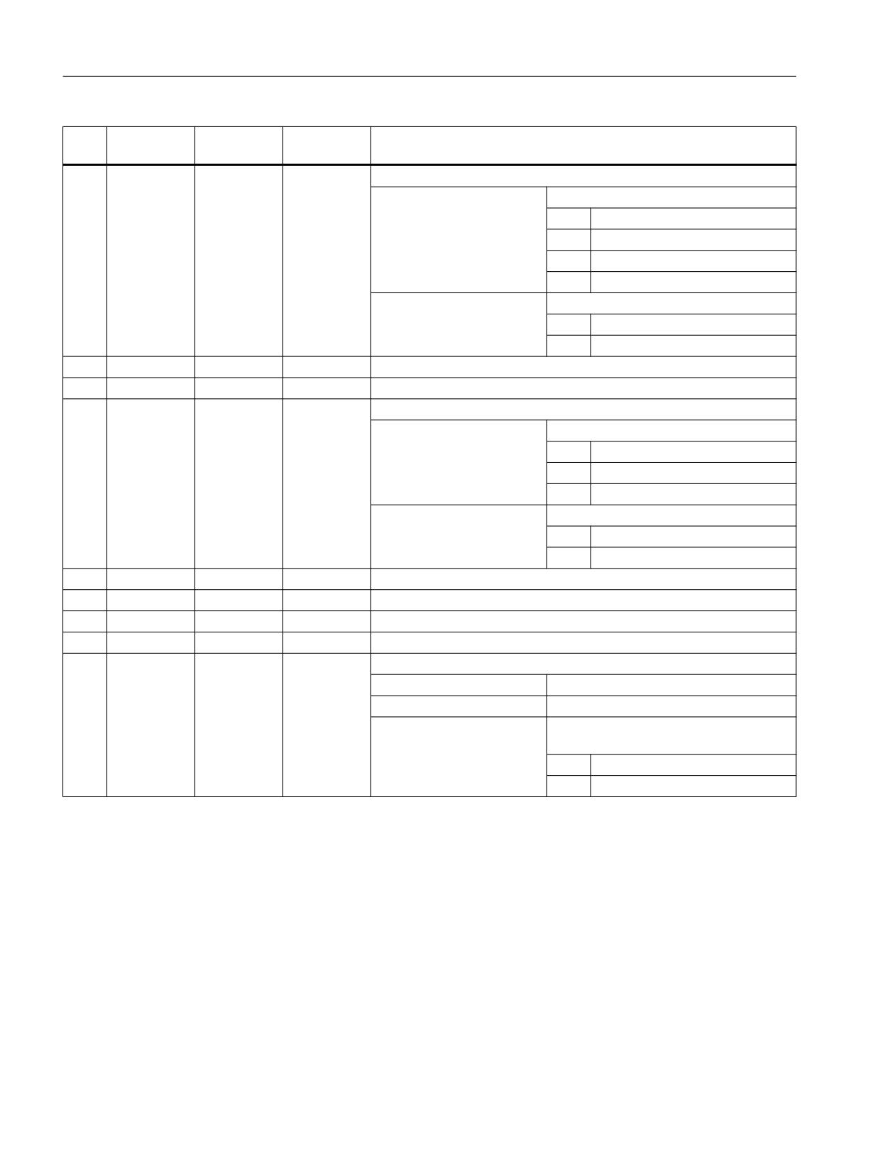
13
<_AS1>
INT
Contour approach movement
UNITS:
1 =
Straight line
2 =
Quadrant
3 =
Semi-circle
4 =
Approach and retraction vertically
TENS:
0 =
Last movement, in the plane
1 =
Last movement, spatial
14
L1
<_LP1>
REAL
Approach path or approach radius (inc; enter without sign)
15
FZ
<_FF3>
REAL
Feedrate for intermediate paths (G94/G95 as to contour)
16
<_AS2>
INT
Contour approach movement (not vertical approach/retract)
UNITS:
1 =
Straight line
2 =
Quadrant
3 =
Semi-circle
TENS:
0 =
Last movement, in the plane
1 =
Last movement, spatial
17
L2
<_LP2>
REAL
Retract path or retract radius (inc, to be entered without sign)
18
<_UMODE>
INT
Reserved
19
FS
<_FS>
REAL
Chamfer width (inc)
20
ZFS
<_ZFS>
REAL
Insertion depth (tool tip) on chamfering (abs/inc), see <_AMODE>
21
<_GMODE>
INT
Geometrical mode (evaluation of programmed geometrical data)
UNITS:
Reserved
TENS:
Reserved
HUNDREDS:
Select machining/only calculation of start
point
0 =
Compatibility mode
1 =
Normal machining
Job Planning
726
Programming Manual, 12/2018, A5E40869460B AB
Programming cycles externally
20.1 Technology cycles
No.
Parameter
Parameter
Data type
Meaning
mask
internal
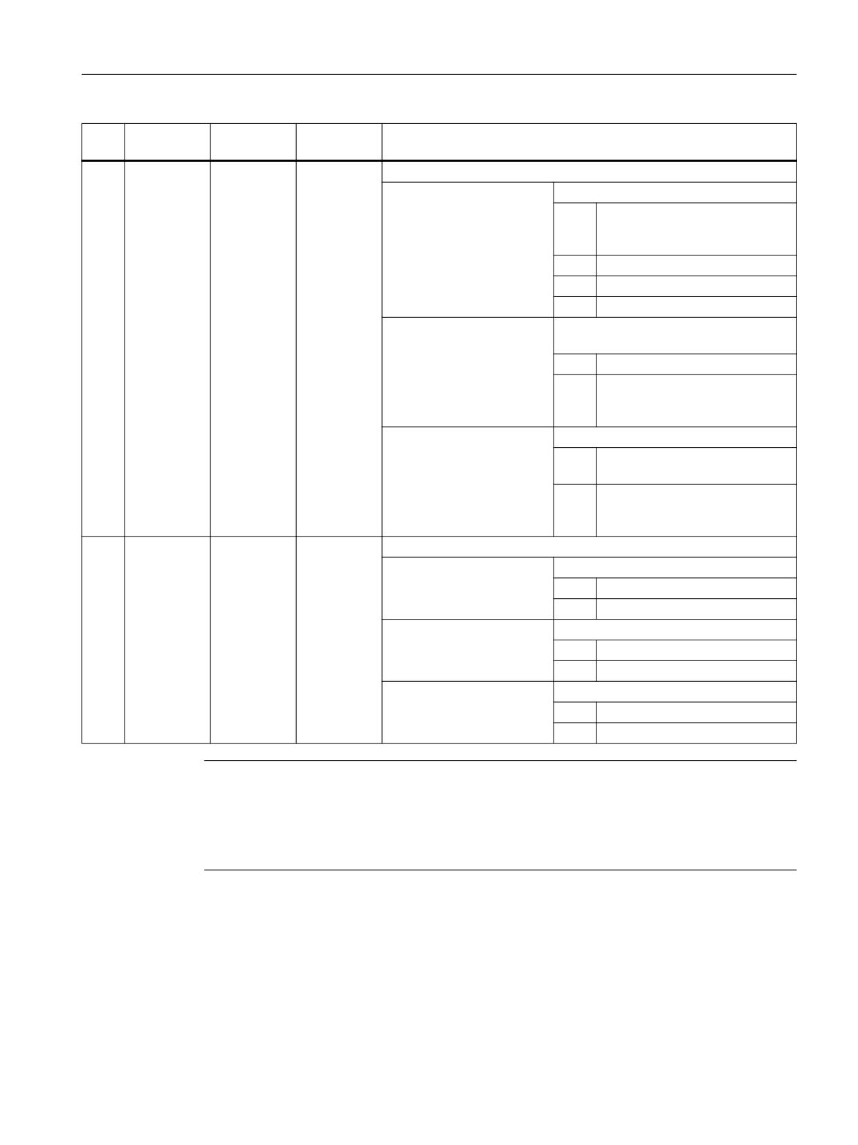
22
<_DMODE>
INT
Display mode
UNITS:
Machining plane G17/18/19
0 =
Compatibility, the plane effective
before the cycle call remains ac-
tive
1 =
G17 (only active in the cycle)
2 =
G18 (only active in the cycle)
3 =
G19 (only active in the cycle)
TENS:
Type of feedrate: G group (G94/G95) for
surface and depth feedrate
0 =
Compatibility mode
1 =
G command as before cycle call.
G94/G95 same for surface and
depth feedrate
THOUSANDS:
0 =
Compatibility mode: Contour
name is in <_KNAME>
1 =
Contour name is programmed in
CYCLE62 and transferred to
_SC_CONT_NAME
23
<_AMODE>
INT
Alternative mode
UNITS:
End point Z1 (<_DP>)
0 =
Absolute (compatibility mode)
1 =
Incremental
TENS:
Units for plane infeed
0 =
mm, inch
1 =
Reserved
HUNDREDS:
Insertion depth for chamfering (<_ZFS>)
0 =
Absolute
1 =
Incremental
Note
If the following transfer parameters are programmed indirectly (as parameters), the screen
form is not reset:
<_VARI>, <_RL>, <_AS1>, <_AS2>, <_UMODE>, <_GMODE>, <_DMODE>,
<_AMODE>
Job Planning
Programming Manual, 12/2018, A5E40869460B AB
727
Programming cycles externally
20.1 Technology cycles
20.1.17
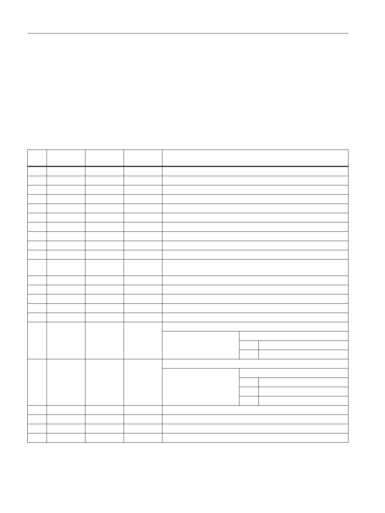
CYCLE76 - rectangular spigot
Syntax
CYCLE76(<_RTP>, <_RFP>, <_SDIS>, <_DP>, <_DPR>, <_LENG>, <_WID>,
<_CRAD>, <_PA>, <_PO>, <_STA>, <_MID>, <_FAL>, <_FALD>, <_FFP1>,
<_FFD>, <_CDIR>, <_VARI>, <_AP1>, <_AP2>, <_FS>, <_ZFS>, <_GMODE>,
<_DMODE>, <_AMODE>)
Parameters
No.
Parameter
Parameter
Data type
Meaning
mask
internal
1
RP
<_RTP>
REAL
Retraction plane (abs)
2
Z0
<_RFP>
REAL
Reference point of tool axis (abs)
3
SC
<_SDIS>
REAL
Safety clearance (to be added to reference point, enter without sign)
4
Z1
<_DP>
REAL
Spigot depth (abs)
5
<_DPR>
REAL
Spigot depth (inc) with respect to Z0 (enter without sign)
6
L
<_LENG>
REAL
Spigot length, see <_GMODE> (enter without sign)
7
W
<_WID>
REAL
Spigot width, see <_GMODE> (enter without sign)
8
R
<_CRAD>
REAL
Spigot corner radius (enter without sign)
9
X0
<_PA>
REAL
Reference point for spigot in 1st axis of plane (abs)
10
Y0
<_PO>
REAL
Reference point for spigot in 2nd axis of plane (abs)
11
α0
<_STA>
REAL
Angle of rotation, angle between longitudinal axis (L) and 1st axis of
plane
12
DZ
<_MID>
REAL
Maximum depth infeed (inc; enter without sign)
13
UXY
<_FAL>
REAL
Finishing allowance, plane (inc), allowance at edge contour
14
UZ
<_FALD>
REAL
Finishing allowance depth (inc), allowance at base (enter without sign)
15
FX
<_FFP1>
REAL
Feedrate on contour
16
FZ
<_FFD>
REAL
Depth infeed rate
17
<_CDIR>
INT
Milling direction (enter without sign)
UNITS:
0 =
Down-cut
1 =
Up-cut
18
<_VARI>
INT
Machining
UNITS:
1 =
Roughing
2 =
Finishing
5 =
Chamfering
19
L1
<_AP1>
REAL
Length of blank spigot
20
W1
<_AP2>
REAL
Width of blank spigot
21
FS
<_FS>
REAL
Chamfer width (inc)
22
ZFS
<_ZFS>
REAL
Insertion depth (tool tip) on chamfering (abs, inc), see <_AMODE>
Job Planning
728
Programming Manual, 12/2018, A5E40869460B AB
Programming cycles externally
20.1 Technology cycles
No.
Parameter
Parameter
Data type
Meaning
mask
internal
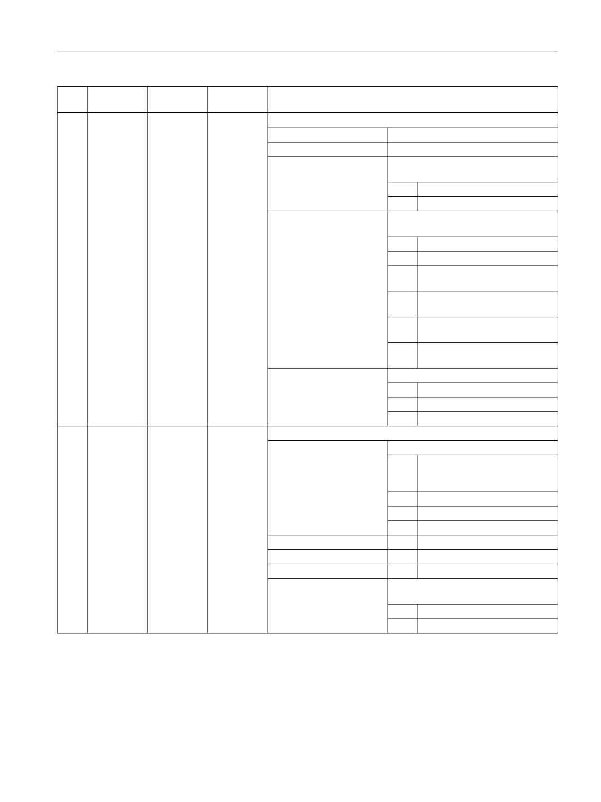
23
<_GMODE>
INT
Geometrical mode (evaluation of programmed geometrical data)
UNITS:
Reserved
TENS:
Reserved
HUNDREDS:
Select machining or just calculation of
start point
0 =
Compatibility mode
1 =
Normal machining
THOUSANDS:
Dimensioning of spigot acc. to center or
corner
0 =
Compatibility mode
1 =
Dimensioning via center
2 =
Dimensioning of corner point,
spigot +L +W
3 =
Dimensioning of corner point,
spigot -L +W
4 =
Dimensioning of corner point,
spigot +L -W
5 =
Dimensioning of corner point,
spigot -L -W
TEN THOUSANDS:
Complete machining or remachining
0 =
Compatibility mode
1 =
Complete machining
2 =
Post machining
24
<_DMODE>
INT
Display mode
UNITS:
Machining plane G17/18/19
0 =
Compatibility, the plane effective
before the cycle call remains ac-
tive
1 =
G17 (only active in the cycle)
2 =
G18 (only active in the cycle)
3 =
G19 (only active in the cycle)
TENS:
---
Reserved
HUNDREDS:
---
Reserved
THOUSANDS:
---
Reserved
TEN THOUSANDS:
Technology scaling in cycle screen
forms (Page 821)
0 =
Input: Complete
1 =
Input: Simple
Job Planning
Programming Manual, 12/2018, A5E40869460B AB
729
Programming cycles externally
20.1 Technology cycles
No.
Parameter
Parameter
Data type
Meaning
mask
internal
25
<_AMODE>
INT
Alternative mode
UNITS:
Final depth Z1 (DP)
0 =
Compatibility
1 =
Incremental
2 =
Absolute
TENS:
Reserved
HUNDREDS:
Insertion depth for chamfering (ZFS)
0 =
Absolute
1 =
Incremental
20.1.18
CYCLE77 - circular spigot
Syntax
CYCLE77(<_RTP>, <_RFP>, <_SDIS>, <_DP>, <_DPR>, <_CDIAM>, <_PA>,
<_PO>, <_MID>, <_FAL>, <_FALD>, <_FFP1>, <_FFD>, <_CDIR>, <_VARI>,
<_AP1>, <_FS>, <_ZFS>, <_GMODE>, <_DMODE>, <_AMODE>)
Parameters
No.
Parameter
Parameter
Data type
Meaning
mask
internal
1
RP
<_RTP>
REAL
Retraction plane (abs)
2
Z0
<_RFP>
REAL
Reference point of tool axis (abs)
3
SC
<_SDIS>
REAL
Safety clearance (to be added to reference point, enter without sign)
4
Z1
<_DP>
REAL
Spigot depth (abs)
5
<_DPR>
REAL
Spigot depth (inc) with respect to Z0 (enter without sign)
6
∅
<_CDIAM>
REAL
Spigot diameter (enter without sign)
7
X0
<_PA>
REAL
Reference point for spigot in 1st axis of plane (abs)
8
Y0
<_PO>
REAL
Reference point for spigot in 2nd axis of plane (abs)
9
DZ
<_MID>
REAL
Maximum depth infeed (inc; enter without sign)
10
UXY
<_FAL>
REAL
Finishing allowance, plane (inc), allowance at edge contour
11
UZ
<_FALD>
REAL
Finishing allowance depth (inc), allowance at base (enter without sign)
12
FX
<_FFP1>
REAL
Feedrate on contour
13
FZ
<_FFD>
REAL
Depth infeed rate
14
<_CDIR>
INT
Milling direction (enter without sign)
UNITS:
0 =
Down-cut
1 =
Up-cut
Job Planning
730
Programming Manual, 12/2018, A5E40869460B AB
Programming cycles externally
20.1 Technology cycles
No.
Parameter
Parameter
Data type
Meaning
mask
internal
15
<_VARI>
INT
Machining type
UNITS:
Machining
1 =
Roughing to final machining al-
lowance
2 =
Finishing (allowance X/Y/Z=0)
5 =
Chamfering
16
∅1
<_AP1>
REAL
Diameter of blank spigot
17
FS
<_FS>
REAL
Chamfer width (inc)
18
ZFS
<_ZFS>
REAL
Insertion depth (tool tip) on chamfering (abs/inc), see <_AMODE>
19
<_GMODE>
INT
Geometrical mode (evaluation of programmed geometrical data)
UNITS:
Reserved
TENS:
Reserved
HUNDREDS:
Select machining/only calculation of start
point
0 =
Compatibility mode
1 =
Normal machining
THOUSANDS:
Reserved
TEN THOUSANDS:
Complete machining/remachining
0 =
Compatibility mode (process
<_AP1> as before)
1 =
Complete machining
2 =
Post machining
20
<_DMODE>
INT
Display mode
UNITS:
Machining plane G17/18/19
0 =
Compatibility, the plane effective
before the cycle call remains ac-
tive
1 =
G17 (only active in the cycle)
2 =
G18 (only active in the cycle)
3 =
G19 (only active in the cycle)
TENS:
---
Reserved
HUNDREDS:
---
Reserved
THOUSANDS:
---
Reserved
TEN THOUSANDS:
Technology scaling in cycle screen
forms (Page 821)
0 =
Input: Complete
1 =
Input: Simple
Job Planning
Programming Manual, 12/2018, A5E40869460B AB
731
Programming cycles externally
20.1 Technology cycles
No.
Parameter
Parameter
Data type
Meaning
mask
internal
21
<_AMODE>
INT
Alternative mode
UNITS:
Final depth Z1 (DP)
0 =
Absolute (compatibility mode)
1 =
Incremental
2 =
Absolute
TENS:
Reserved
HUNDREDS:
Insertion depth for chamfering (ZFS)
0 =
Absolute
1 =
Incremental
20.1.19
CYCLE78 - Drill thread milling
Syntax
CYCLE78(<_RTP>, <_RFP>, <_SDIS>, <_DP>, <_ADPR>, <_FDPR>, <_LDPR>,
<_DIAM>, <_PIT>, <_PITA>, <_DAM>, <_MDEP>, <_VARI>, <_CDIR>, <_GE>,
<_FFD>, <_FRDP>, <_FFR>, <_FFP2>, <_FFA>, <_PITM>, <_PTAB>,
<_PTABA>, <_GMODE>, <_DMODE>, <_AMODE>)
Parameters
No.
Parameter
Parameter
Data type
Meaning
mask
internal
1
RP
<_RTP>
REAL
Retraction plane (abs)
2
Z0
<_RFP>
REAL
Reference point of tool axis (abs)
3
SC
<_SDIS>
REAL
Safety clearance (to be added to reference point, enter without sign)
4
Z1
<_DP>
REAL
Final drilling depth (abs/inc), see <_AMODE>
5
<_ADPR>
REAL
Predrilling depth with reduced drilling feedrate (inc) effective with
<_VARI> TEN THOUSANDS
6
D
<_FDPR>
REAL
Maximum depth infeed (inc)
D ≥ Z1 ⇒ One infeed to the final drilling depth
D < Z1 ⇒ Deep drilling cycle with multiple infeeds and chip removal
7
ZR
<_LDPR>
REAL
Remaining drilling depth when through-drilling (inc) with FR feed
8
∅
<_DIAM>
REAL
Nominal diameter of the thread
9
P
<_PIT>
REAL
Pitch as a numerical value
10
<_PITA>
INT
Evaluation of thread pitch P
1 =
Pitch in mm/rev
2 =
Pitch in threads/inch
3 =
Pitch in inch/rev
4 =
Pitch as MODULE
11
DF
<_DAM>
REAL
Absolute value / percentage for each additional infeed (degression),
see<_AMODE>
Job Planning
732
Programming Manual, 12/2018, A5E40869460B AB
Programming cycles externally
20.1 Technology cycles
No.
Parameter
Parameter
Data type
Meaning
mask
internal
12
V1
<_MDEP>
REAL
Minimum infeed (inc), only active for degression
13
<_VARI>
INT
Machining type
UNITS:
Reserved
TENS:
Swarf removal before thread milling
0 =
No chip removal before thread
milling (only active at final drilling
depth)
1 =
Chip removal before thread mill-
ing (only active at final drilling
depth)
HUNDREDS:
Right-hand/left-hand threads
0 =
Right-hand thread
1 =
Left-hand thread
THOUSANDS:
Remaining drilling depth with drilling fee-
drate
0 =
No remaining drilling depth with
drilling feedrate FR
1 =
Remaining drilling depth with drill-
ing feedrate FR
TEN THOUSANDS:
Predrilling with reduced feedrate
0 =
No predrilling with reduced fee-
drate
1 =
Predrilling with reduced feedrate
Predrilling feedrate = 0.3 F1, if
F1 < 0.15 mm/rev
Predrilling feedrate = 0.1 mm/rev,
if F1 ≥ 0.15 mm/rev
14
<_CDIR>
INT
Milling direction
0 =
Down-cut
1 =
Up-cut
4 =
Up-cut + down-cut (combined
roughing + finishing)
15
Z2
<_GE>
REAL
Retraction distance before thread milling (inc)
16
F1
<_FFD>
REAL
Drilling feedrate (mm/min or in/min or mm/rev)
17
FR
<_FRDP>
REAL
Drilling feedrate for remaining drilling depth (mm/min or mm/rev)
18
F2
<_FFR>
REAL
Feedrate for thread milling (mm/min or mm/tooth)
19
FS
<_FFP2>
REAL
Finishing feedrate for
<_CDIR> =4 (mm/min or mm/tooth)
20
<_FFA>
INT
Evaluation of feedrates
UNITS:
Drilling feed F1
TENS:
Drilling feedrate for remaining drilling
depth FR
HUNDREDS:
Feedrate for thread milling F2
THOUSANDS:
Finishing feedrate FS
21
<_PITM>
STRING[15]
String as marker for pitch input (for the interface only)1)
22
<_PTAB>
STRING[20]
String for thread table ("", "ISO", "BSW", "BSP", "UNC") (for the interface
only)1)
Job Planning
Programming Manual, 12/2018, A5E40869460B AB
733
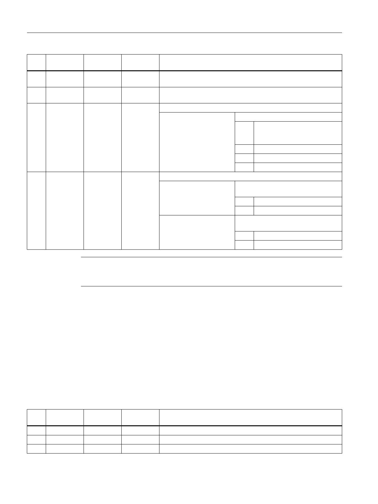
Programming cycles externally
20.1 Technology cycles
No.
Parameter
Parameter
Data type
Meaning
mask
internal
23
<_PTABA>
STRING[20]
String for selection from thread table (e.g. "M 10", "M 12", ...) (for the
interface only)1)
24
<_GMODE>
INT
Geometrical mode (evaluation of programmed geometrical data), re-
served
25
<_DMODE>
INT
Display mode
UNITS:
Machining plane G17/18/19
0 =
Compatibility, the plane effective
before the cycle call remains ac-
tive
1 =
G17 (only active in the cycle)
2 =
G18 (only active in the cycle)
3 =
G19 (only active in the cycle)
26
<_AMODE>
INT
Alternative mode
UNITS:
Drilling depth = Final drilling depth Z1
abs/inc
0 =
Absolute
1 =
Incremental
TENS:
Absolute value / percentage DF for each
additional infeed (degression)
0 =
Absolute value
1 =
Percentage (0.001 to 100%)
Note
1) Parameters 21, 22 and 23 are only used for thread selection in the screen form thread tables.
The thread tables cannot be accessed via cycle definition in the cycle run time.
20.1.20
CYCLE79 - multi-edge
Syntax
CYCLE79(<_RTP>, <_RFP>, <_SDIS>, <_DP>, <_NUM>, <_SWL>, <_PA>,
<_PO>, <_STA>, <_RC>, <_AP1>, <_MIDA>, <_MID>, <_FAL>, <_FALD>,
<_FFP1>, <_CDIR>, <_VARI>, <_FS>, <_ZFS>, <_GMODE>, <_DMODE>,
<_AMODE>)
Parameters
No.
Parameter
Parameter
Data type
Meaning
mask
internal
1
RP
<_RTP>
REAL
Retraction plane (abs)
2
Z0
<_RFP>
REAL
Reference point of tool axis (abs)
3
SC
<_SDIS>
REAL
Safety clearance (to be added to reference point, enter without sign)
Job Planning
734
Programming Manual, 12/2018, A5E40869460B AB
Programming cycles externally
20.1 Technology cycles
No.
Parameter
Parameter
Data type
Meaning
mask
internal
4
Z1
<_DP>
REAL
Multiple-edge depth (abs/inc), see <_AMODE>
5
N
<_NUM>
INT
Number of edges (1...n)
6
SW/L
<_SWL>
REAL
Width across flats or edge length (depending on <_VARI>)
("SW" for width across flats, "L" for edge length)
Width across flats only if even number of edges, and single edge
7
X0
<_PA>
REAL
Spigot reference point, 1st axis (abs)
8
Y0
<_PO>
REAL
Spigot reference point, 2nd axis (abs)
9
α0
<_STA>
REAL
Angle of rotation, center of edge against 1st axis (X axis)
10
R1/FS1
<_RC>
REAL
Corner rounding with <_NUM> > 2 (radius/chamfer, see <_AMODE>)
(inc, to be entered without sign)
("R1" for radius, "FS1" for chamfer)
11
∅
<_AP1>
REAL
Unmachined diameter of spigot
12
DXY
<_MIDA>
REAL
Maximum infeed width (for unit, see <_AMODE>)
13
DZ
<_MID>
REAL
Maximum depth infeed
14
UXY
<_FAL>
REAL
Finishing allowance, plane
15
UZ
<_FALD>
REAL
Finishing allowance, depth
16
F
<_FFP1>
REAL
Machining feedrate
17
<_CDIR>
INT
Milling direction
0 =
Down-cut
1 =
Up-cut
18
<_VARI>
INT
Machining type
UNITS:
Machining
1 =
Roughing
2 =
Finishing
3 =
Edge finishing
5 =
Chamfering
TENS:
Width across flats or edge length
0 =
Width across flats
1 =
Edge length
19
FS
<_FS>
REAL
Chamfer width (inc)
20
ZFS
<_ZFS>
REAL
Insertion depth (tool tip) on chamfering (abs/inc), see <_AMODE>
21
<_GMODE>
INT
Geometrical mode (evaluation of programmed geometrical data)
UNITS:
Reserved
TENS:
Reserved
HUNDREDS:
Select machining or just calculation of
start point
1 =
Normal machining
Job Planning
Programming Manual, 12/2018, A5E40869460B AB
735
Programming cycles externally
20.1 Technology cycles
No.
Parameter
Parameter
Data type
Meaning
mask
internal
22
<_DMODE>
INT
Display mode
UNITS:
Machining plane G17/18/19
0 =
Compatibility, the plane effective
before the cycle call remains ac-
tive
1 =
G17 (only active in the cycle)
2 =
G18 (only active in the cycle)
3 =
G19 (only active in the cycle)
TENS:
---
Reserved
HUNDREDS:
---
Reserved
THOUSANDS:
---
Reserved
TEN THOUSANDS:
Technology scaling in cycle screen
forms (Page 821)
0 =
Input: Complete
1 =
Input: Simple
23
<_AMODE>
INT
Alternative mode
UNITS:
Final depth (<_DP>)
0 =
Absolute
1 =
Incremental
TENS:
Units for plane infeed (<_MIDA>)
0 =
mm
1 =
% of tool diameter
HUNDREDS:
Insertion depth for chamfering (<_ZFS>)
0 =
Absolute
1 =
Incremental
THOUSANDS:
Corner rounding (<_RC>)
0 =
Radius
1 =
Chamfer
20.1.21
CYCLE81 - drilling, centering
Syntax
CYCLE81(<RTP>, <RFP>, <SDIS>, <DP>, <DPR>, <DTB>, <_GMODE>,
<_DMODE>, <_AMODE>)
Parameter
No.
Parameter
Parameter
Data type
Meaning
mask
internal
1
RP
<RTP>
REAL
Retraction plane (abs)
2
Z0
<RFP>
REAL
Reference point (abs)
Job Planning
736
Programming Manual, 12/2018, A5E40869460B AB
Programming cycles externally
20.1 Technology cycles
No.
Parameter
Parameter
Data type
Meaning
mask
internal
3
SC
<SDIS>
REAL
Safety clearance (to be added to reference point, enter without sign)
4
Z1/∅
<DP>
REAL
Drilling depth (abs) / centering diameter (abs), see <_GMODE>
5
Z1
<DPR>
REAL
Drilling depth (inc)
6
DT
<DTB>
REAL
Dwell time at final drilling depth, see <_AMODE>
7
<_GMODE>
INT
Geometrical mode (evaluation of programmed geometrical data)
UNITS:
Reserved
TENS:
Centering with respect to depth/diameter
0 =
Compatibility, depth
1 =
Diameter
8
<_DMODE>
INT
Display mode
UNITS:
Machining plane G17/G18/G19
0 =
Compatibility, the plane effective
before the cycle call remains ac-
tive
1 =
G17 (only active in the cycle)
2 =
G18 (only active in the cycle)
3 =
G19 (only active in the cycle)
9
<_AMODE>
INT
Alternative mode
UNITS:
Drilling depth Z1 (abs/inc)
0 =
Compatibility, from DP/DPR pro-
gramming
1 =
Incremental
2 =
Absolute
TENS:
Dwell time at final drilling depth DT in
seconds/revolutions
0 =
Compatibility, from DTB sign (> 0
seconds or < 0 revolutions)
1 =
In seconds
2 =
In revolutions
20.1.22
CYCLE82 - drilling, counterboring
Syntax
CYCLE82(<RTP>, <RFP>, <SDIS>, <DP>, <DPR>, <DTB>, <_GMODE>,
<_DMODE>, <_AMODE>, <_VARI>, <S_ZA>, <S_FA>, <S_ZD>, <S_FD>)
Job Planning
Programming Manual, 12/2018, A5E40869460B AB
737
Programming cycles externally
20.1 Technology cycles
Parameter
No.
Parameter
Parameter
Data type
Meaning
mask
internal
1
RP
<RTP>
REAL
Retraction plane (abs)
2
Z0
<RFP>
REAL
Reference point (abs)
3
SC
<SDIS>
REAL
Safety clearance (to be added to reference point, enter without sign)
4
Z1
<DP>
REAL
Drilling depth (abs), see <_AMODE>
5
Z1
<DPR>
REAL
Drilling depth (inc), see <_AMODE>
6
DT
<DTB>
REAL
Dwell time at final drilling depth, see <_AMODE>
7
<_GMODE>
INT
Geometrical mode (evaluation of programmed geometrical data)
UNITS:
Reserved
TENS:
Drilling depth with respect to tip/shank
0 =
Compatibility, tip
1 =
Shank
8
<_DMODE>
INT
Display mode
UNITS:
Machining plane G17/G18/G19
0 =
Compatibility, the plane effective
before the cycle call remains ac-
tive
1 =
G17 (only active in the cycle)
2 =
G18 (only active in the cycle)
3 =
G19 (only active in the cycle)
TENS:
Reserved
HUNDREDS:
Reserved
THOUSANDS:
Reserved
TEN THOUSANDS:
Technology scaling in cycle screen
forms (Page 821)
0 =
Input: Complete
1 =
Input: Basic
Job Planning
738
Programming Manual, 12/2018, A5E40869460B AB
Programming cycles externally
20.1 Technology cycles
No.
Parameter
Parameter
Data type
Meaning
mask
internal
9
<_AMODE>
INT
Alternative mode
UNITS:
Drilling depth Z1 (abs/inc)
0 =
Compatibility, from DP/DPR pro-
gramming
1 =
Incremental
2 =
Absolute
TENS:
Dwell time DT at final drilling depth in
seconds/revolutions
0 =
Compatibility, from DT sign (> 0
seconds / < 0 revolutions)
1 =
In seconds
2 =
In revolutions
HUNDREDS:
Drilling depth ZA abs/inc
0 =
Incremental
1 =
Absolute
THOUSANDS:
Evaluation of predrilling feedrate
0 =
As % of drilling feedrate
1 =
F/min
2 =
F/rev
TEN THOUSANDS:
Remaining drilling depth ZD abs/inc
0 =
Incremental
1 =
Absolute
HUNDRED THOUSANDS:
Evaluation of remaining drilling feedrate
0 =
As % of drilling feedrate
1 =
F/min
2 =
F/rev
10
<_VARI>
INT
Predrilling/through-drilling machining type
UNITS:
Reserved
TENS:
Reserved
HUNDREDS:
Reserved
THOUSANDS:
Through drilling
0 =
Through drilling "No"
1 =
Through drilling "Yes"
TEN THOUSANDS:
Predrilling
0 =
Predrilling "No"
1 =
Predrilling "Yes"
11
ZA
<S_ZA>
REAL
Incremental predrilling depth in relation to reference point or absolute
(see <_AMODE> HUNDREDS)
12
FA
<S_FA>
REAL
Predrilling feedrate as value or in % (in conjunction with <_AMODE>
THOUSANDS)
Job Planning
Programming Manual, 12/2018, A5E40869460B AB
739
Programming cycles externally
20.1 Technology cycles
No.
Parameter
Parameter
Data type
Meaning
mask
internal
13
ZD
<S_ZD>
REAL
Incremental remaining drilling depth in relation to final drilling depth or
absolute (see <_AMODE> TEN THOUSANDS)
14
FD
<S_FD>
REAL
Remaining drilling feedrate as value or in % (in conjunction with
<_AMODE> HUNDRED THOUSANDS)
20.1.23
CYCLE83 - deep-hole drilling 1
Syntax
CYCLE83(<RTP>, <RFP>, <SDIS>, <DP>, <DPR>, <FDEP>, <FDPR>, <_DAM>,
<DTB>, <DTS>, <FRF>, <VARI>, <_AXN>, <_MDEP>, <_VRT>, <_DTD>,
<_DIS1>, <_GMODE>, <_DMODE>, <_AMODE>)
Parameter
No.
Parameter
Parameter
Data type
Meaning
mask
internal
1
RP
<RTP>
REAL
Retraction plane (abs)
2
Z0
<RFP>
REAL
Reference point (abs)
3
SC
<SDIS>
REAL
Safety clearance (to be added to reference point, enter without sign)
4
Z1
<DP>
REAL
Final drilling depth (abs), see <_AMODE>
5
Z1
<DPR>
REAL
Final drilling depth (inc), see <_AMODE>
6
D
<FDEP>
REAL
1st drilling depth (abs), see <_AMODE>
7
D
<FDPR>
REAL
1st drilling depth (inc), see <_AMODE>
8
DF
<_DAM>
REAL
Degression value / percentage for each additional infeed, see
<_AMODE>
9
DTB
<DTB>
REAL
Dwell time at drilling depth, see <_AMODE>
10
DTS
<DTS>
REAL
Dwell time at start point (for chip removal only), see <_AMODE>
11
FD1
<FRF>
REAL
Percentage for the feedrate for the first infeed, see <_AMODE>
12
<VARI>
INT
Machining type
UNITS:
Chip breaking/removal
0 =
Chip breaking
1 =
Swarf removal
13
<_AXN>
INT
Tool axis
0 =
3rd geometry axis
1 =
1st geometry axis
2 =
2nd geometry axis
> 2
3rd geometry axis
14
V1
<_MDEP>
REAL
Minimum infeed (only for degression percentage)
15
V2
<_VRT>
REAL
Retraction distance after each machining step (for chip breaking only)
> 0
Variable retraction distance
0 =
Default value 1 mm
Job Planning
740
Programming Manual, 12/2018, A5E40869460B AB
Programming cycles externally
20.1 Technology cycles
No.
Parameter
Parameter
Data type
Meaning
mask
internal
16
DT
<_DTD>
REAL
Dwell time at final drilling depth, see <_AMODE>
17
V3
<_DIS1>
REAL
Limit distance (for chip removal only), see <_AMODE>
18
<_GMODE>
INT
Geometrical mode (evaluation of programmed geometrical data)
UNITS:
Reserved
TENS:
Drilling depth with respect to tip/shank
0 =
Tip
1 =
Shank
19
<_DMODE>
INT
Display mode
UNITS:
Machining plane G17/G18/G19
0 =
Compatibility, the plane effective
before the cycle call remains ac-
tive
1 =
G17 (only active in the cycle)
2 =
G18 (only active in the cycle)
3 =
G19 (only active in the cycle)
TENS:
---
Reserved
HUNDREDS:
---
Reserved
THOUSANDS:
---
Reserved
TEN THOUSANDS:
Technology scaling in cycle screen
forms (Page 821)
0 =
Input: Complete
1 =
Input: Simple
Job Planning
Programming Manual, 12/2018, A5E40869460B AB
741
Programming cycles externally
20.1 Technology cycles
No.
Parameter
Parameter
Data type
Meaning
mask
internal
20
<_AMODE>
INT
Alternative mode
UNITS:
Drilling depth = Final drilling depth Z1
(abs/inc)
0 =
Compatibility, from programming
<DP>/<DPR>
1 =
Incremental
2 =
Absolute
TENS:
Dwell time at drilling depth DTB in sec-
onds/revolutions
0 =
Compatibility, from DTB sign (> 0
seconds or < 0 revolutions)
1 =
In seconds
2 =
In revolutions
HUNDREDS:
Dwell time at start point of DTS in sec-
onds/revolutions
0 =
Compatibility, from DTS sign (> 0
seconds or < 0 revolutions)
1 =
In seconds
2 =
In revolutions
THOUSANDS:
Dwell time at final drilling depth DTD in
seconds/revolutions
0 =
Compatibility, from DTD sign (> 0
seconds or < 0 revolutions)
1 =
In seconds
2 =
In revolutions
TEN THOUSANDS:
1st drilling depth D (abs/inc)
0 =
Compatibility, from programming
<FDEPF>/<DPR>
1 =
Incremental
2 =
Absolute
HUNDRED THOUSANDS:
Degression value / percentage <_DAM>
for each additional infeed
0 =
Compatibility, from <_DAM> sign
(> 0 degression value or < 0 fac-
tor 0.001 to 1.0)
1 =
Degression value
2 =
Percentage (0.001 to 100%)
ONE MILLION:
Limit distance V3 automatic/manual
0 =
Compatibility from <_DIS1> sign
(= 0 automatic or > 0 manual)
1 =
Automatic (calculated in the cy-
cle)
2 =
Manual (programmed value)
TEN MILLIONS:
Feedrate factor for first infeed <FRF> as
factor/percentage
Job Planning
742
Programming Manual, 12/2018, A5E40869460B AB
Programming cycles externally
20.1 Technology cycles
No.
Parameter
Parameter
Data type
Meaning
mask
internal
0 =
Compatibility, as a factor (0.001
to 1.0, FRF = 0 means 100%)
1 =
Percentage (0.001 to 999.999%)
20.1.24
CYCLE84 - tapping without compensating chuck
Syntax
CYCLE84(<RTP>, <RFP>, <SDIS>, <DP>, <DPR>, <DTB>, <SDAC>, <MPIT>,
<PIT>, <POSS>, <SST>, <SST1>, <_AXN>, <_PITA>, <_TECHNO>, <_VARI>,
<_DAM>, <_VRT>, <_PITM>, <_PTAB>, <_PTABA>, <_GMODE>, <_DMODE>,
<_AMODE>)
Parameters
No.
Parameter
Parameter
Data type
Meaning
mask
internal
1
RP
<RTP>
REAL
Retraction plane (abs)
2
Z0
<RFP>
REAL
Reference point (abs)
3
SC
<SDIS>
REAL
Safety clearance (to be added to reference point, enter without sign)
4
Z1
<DP>
REAL
Drilling depth = final drilling depth (abs), see <_AMODE>
5
Z1
<DPR>
REAL
Drilling depth = final drilling depth (inc), see <_AMODE>
6
DT
<DTB>
REAL
Dwell time at drilling depth in seconds
7
SDE
<SDAC>
INT
Direction of rotation after end of cycle
8
<MPIT>
REAL
Thread size for "ISO metric" only (pitch is calculated internally during run
time)
9
P
<PIT>
REAL
Pitch as a value, for unit see <_PITA>
10
αS1)
<POSS>
REAL
Spindle position for oriented spindle stop
11
S
<SST>
REAL
Spindle speed for tapping
12
SR
<SST1>
REAL
Spindle speed for retraction
13
<_AXN>
INT
Drilling axis
0 =
3rd geometry axis
1 =
1st geometry axis
2 =
2nd geometry axis
≥ 3 =
3rd geometry axis
Job Planning
Programming Manual, 12/2018, A5E40869460B AB
743
Programming cycles externally
20.1 Technology cycles
No.
Parameter
Parameter
Data type
Meaning
mask
internal
14
<_PITA>
INT
Pitch unit (evaluation of <PIT> and <MPIT>)
0 =
Pitch in mm
- evalua-
tion<MPIT>/
<PIT>
1 =
Pitch in mm
- evaluation<PIT>
2 =
Pitch in TPI
- evaluation of
<PIT>
(threads per inch)
3 =
Pitch in inches
- evaluation<PIT>
4 =
MODULUS
- evaluation<PIT>
15
<_TECHNO>
INT
Technology1)
UNITS:
Exact stop response
0 =
Exact stop response active as before cy-
cle call
1 =
Exact stop G601
2 =
Exact stop G602
3 =
Exact stop G603
TENS:
Feedforward control
0 =
With/without feedforward control active
as before cycle call
1 =
With feedforward control FFWON
2 =
Without feedforward control FFWOF
HUNDREDS:
Acceleration
0 =
SOFT/BRISK/DRIVE active as before cy-
cle call
1 =
With jerk limitation SOFT
2 =
Without jerk limitation BRISK
3 =
Reduced acceleration DRIVE
THOUSANDS:
MCALL spindle mode
0 =
Reactivate spindle operation for MCALL
1 =
For MCALL remain in position control
16
<_VARI>
INT
Machining type
UNITS:
0 =
1 cut
1 =
Chip breaking (deep hole tapping)
2 =
Chip removal (deep hole tapping)
THOUSANDS:
ISO/SIEMENS mode not relevant for screen form
0 =
Call from ISO compatibility
1 =
Call from SIEMENS context
17
D
<_DAM>
REAL
Maximum depth infeed (for chip removal/breaking only)
18
V2
<_VRT>
REAL
Retraction distance after each machining step (for chip breaking only),
see <_AMODE>
19
<_PITM>
STRING[15]
String as marker for pitch input2)
20
<_PTAB>
STRING[5]
String for thread table ("", "ISO", "BSW", "BSP", "UNC")2)
21
<_PTABA>
STRING[20]
String for selection from thread table (e.g. "M 10", "M 12", ...)2)
Job Planning
744
Programming Manual, 12/2018, A5E40869460B AB
Programming cycles externally
20.1 Technology cycles
No.
Parameter
Parameter
Data type
Meaning
mask
internal
22
<_GMODE>
INT
Geometrical mode (evaluation of programmed geometrical data)
UNITS:
Reserved
TENS:
Reserved
23
<_DMODE>
INT
Display mode
UNITS:
Machining plane G17/G18/G19
0 =
Compatibility, the plane effective before
the cycle call remains active
1 =
G17 (only active in the cycle)
2 =
G18 (only active in the cycle)
3 =
G19 (only active in the cycle)
TENS:
Reserved
HUNDREDS:
Reserved
THOUSANDS:
Compatibility mode (for recompilation screen
form only),
if MD 52216 bit0 = 11)
0 =
Technology parameters are displayed
(compatibility): TECHNO parameters ef-
fective
1 =
Technology parameters are not dis-
played: Technology active "as before cy-
cle call"
TEN THOUSANDS:
Technology scaling in cycle screen forms
(Page 821)
0 =
Input: Complete
1 =
Input: Simple
Job Planning
Programming Manual, 12/2018, A5E40869460B AB
745
Programming cycles externally
20.1 Technology cycles
No.
Parameter
Parameter
Data type
Meaning
mask
internal
24
<_AMODE>
INT
Alternative mode
UNITS:
Drilling depth = Final drilling depth Z1 (abs/inc)
0 =
Compatibility, from programming <DP>/
<DPR>
1 =
Incremental
2 =
Absolute
TENS:
Reserved
HUNDREDS:
Reserved
THOUSANDS:
Thread direction of rotation right/left
0 =
Compatibility, from PIT/MPTI sign
1 =
Right
2 =
Left
TEN THOUSANDS:
Reserved
HUNDRED THOU-
Reserved
SANDS:
ONE MILLION:
Retraction distance after each machining step
V2 manual/automatic
0 =
Compatibility, from <_VRT> program-
ming (> 0 variable value or ≤ 0 standard
value 1 mm / 0.0394 inch)
1 =
Automatic (standard value 1 mm / 0.0394
inch)
2 =
Manual (programmed as under V2)
1) Technology fields may be hidden, depending on the setting date SD52216 $MCS_FUNCTION_MASK_DRILL
2) Parameters 19, 20 and 21 are only used for thread selection in the screen form thread tables. The thread tables cannot
be accessed via cycle definition in the cycle run time.
20.1.25
CYCLE85 - reaming
Syntax
CYCLE85(<RTP>, <RFP>, <SDIS>, <DP>, <DPR>, <DTB>, <FFR>, <RFF>,
<_GMODE>, <_DMODE>, <_AMODE>)
Parameter
No.
Parameter
Parameter
Data type
Meaning
mask
internal
1
RP
<RTP>
REAL
Retraction plane (abs)
2
Z0
<RFP>
REAL
Reference point (abs)
3
SC
<SDIS>
REAL
Safety clearance (to be added to reference point, enter without sign)
4
Z1
<DP>
REAL
Drilling depth (abs), see <_AMODE>
5
Z1
<DPR>
REAL
Drilling depth (inc), see <_AMODE>
Job Planning
746
Programming Manual, 12/2018, A5E40869460B AB
Programming cycles externally
20.1 Technology cycles
No.
Parameter
Parameter
Data type
Meaning
mask
internal
6
DT
<DTB>
REAL
Dwell time at final drilling depth, see <_AMODE>
7
F
<FFR>
REAL
Feedrate
8
FR
<RFF>
REAL
Feedrate during retraction
9
<_GMODE>
INT
Reserved
10
<_DMODE>
INT
Display mode
UNITS:
Machining plane G17/G18/G19
0 =
Compatibility, the plane effective
before the cycle call remains ac-
tive
1 =
G17 (only active in the cycle)
2 =
G18 (only active in the cycle)
3 =
G19 (only active in the cycle)
11
<_AMODE>
INT
Alternative mode (drilling)
UNITS:
Drilling depth Z1 (abs/inc)
0 =
Compatibility, from DP/DPR pro-
gramming
1 =
Incremental
2 =
Absolute
TENS:
Dwell time DT at final drilling depth in
seconds/revolutions
0 =
Compatibility, from DT sign (> 0
seconds or < 0 revolutions)
1 =
In seconds
2 =
In revolutions
20.1.26
CYCLE86 - boring
Syntax
CYCLE86(<RTP>, <RFP>, <SDIS>, <DP>, <DPR>, <DTB>, <SDIR>, <RPA>,
<RPO>, <RPAP>, <POSS>, <_GMODE>, <_DMODE>, <_AMODE>)
Parameters
No.
Parameter
Parameter
Data type
Meaning
mask
internal
1
RP
<RTP>
REAL
Retraction plane (abs)
2
Z0
<RFP>
REAL
Reference point (abs)
3
SC
<SDIS>
REAL
Safety clearance (to be added to reference point, enter without sign)
4
Z1
<DP>
REAL
Drilling depth (abs), see <_AMODE>
5
Z1
<DPR>
REAL
Drilling depth (inc), see <_AMODE>
6
DT
<DTB>
REAL
Dwell time at final drilling depth, see <_AMODE>
Job Planning
Programming Manual, 12/2018, A5E40869460B AB
747
Programming cycles externally
20.1 Technology cycles
No.
Parameter
Parameter
Data type
Meaning
mask
internal
7
DIR
<SDIR>
INT
Direction of spindle rotation
3 =
M3
4 =
M4
8
DX
<RPA>
REAL
Lift-off distance in X direction
9
DY
<RPO>
REAL
Lift-off distance in the Y direction
10
DZ
<RPAP>
REAL
Lift-off distance in the Z direction
11
SPOS
<POSS>
REAL
Spindle position for lift-off (for oriented spindle stop, in degrees)
12
<_GMODE>
INT
Geometrical mode (evaluation of programmed geometrical data)
UNITS:
Lift mode
0 =
Lift off, compatibility
1 =
Do not lift off contour
13
<_DMODE>
INT
Display mode
UNITS:
Machining plane G17/G18/G19
0 =
Compatibility, the plane effective
before the cycle call remains ac-
tive
1 =
G17 (only active in the cycle)
2 =
G18 (only active in the cycle)
3 =
G19 (only active in the cycle)
14
<_AMODE>
INT
Alternative mode
UNITS:
Drilling depth Z1 (abs/inc)
0 =
Compatibility, from program-
ming<DP>/<DPR>
1 =
Incremental
2 =
Absolute
TENS:
Dwell time at final drilling depth DT in
seconds/revolutions
0 =
Compatibility, from DT sign (> 0
seconds or < 0 revolutions)
1 =
In seconds
2 =
In revolutions
20.1.27
CYCLE92 - cut-off
Syntax
CYCLE92(<_SPD>, <_SPL>, <_DIAG1>, <_DIAG2>, <_RC>, <_SDIS>, <_SV1>,
<_SV2>, <_SDAC>, <_FF1>, <_FF2>, <_SS2>, <_DIAGM>, <_VARI>, <_DN>,
<_DMODE>, <_AMODE>)
Job Planning
748
Programming Manual, 12/2018, A5E40869460B AB
Programming cycles externally
20.1 Technology cycles
Parameters
No.
Parameter
Parameter
Data type
Meaning
mask
internal
1
X0
<_SPD>
REAL
Reference point (abs, always diameter)
2
Y0
<_SPL>
REAL
Reference point (abs)
3
X1
<_DIAG1>
REAL
Depth for speed reduction, see <_AMODE> (UNITS)
4
X2
<_DIAG2>
REAL
Final depth, see <_AMODE> (TENS)
5
R/FS
<_RC>
REAL
Rounding status or chamfer width, see <_AMODE> (THOUSANDS)
6
SC
<_SDIS>
REAL
Safety clearance (to be added to reference point, enter without sign)
7
S
<_SV1>
REAL
Constant spindle speed, see <_AMODE> (TEN THOUSANDS)
V
Constant cutting rate
8
SV
<_SV2>
REAL
Maximum speed at constant cutting speed
9
DIR
<_SDAC>
INT
Direction of spindle rotation
3 =
For M3
4 =
For M4
10
F
<_FF1>
REAL
Infeed as far as depth for speed reduction
11
FR
<_FF2>
REAL
Reduced infeed as far as final depth
12
SR
<_SS2>
REAL
Reduced speed as far as final depth
13
XM
<_DIAGM>
REAL
Depth to withdraw parts gripper (abs, always diameter)
14
<_VARI>
INT
Machining type
UNITS:
Retraction
0 =
Retraction to <_SPD> + <_SDIS>
1 =
No retraction at the end
TENS:
Parts gripper
0 =
No, do not execute M command
1 =
Yes, call from CUST_TECH-
CYC(101)- open drawer,
CUST_TECHCYC(102)- close
drawer
15
<_DN>
INT
D number for 2nd edge of tool; if not programmed ⇒ D+1
20
<_DMODE>
INT
Display mode
UNITS:
Machining plane G17/G18/G19
0 =
Compatibility, the plane effective
before the cycle call remains ac-
tive
1 =
G17 (only active in the cycle)
2 =
G18 (only active in the cycle)
3 =
G19 (only active in the cycle)
Job Planning
Programming Manual, 12/2018, A5E40869460B AB
749
Programming cycles externally
20.1 Technology cycles
No.
Parameter
Parameter
Data type
Meaning
mask
internal
21
<_AMODE>
INT
Alternative mode
UNITS:
Depth for speed reduction (<_DIAG1>)
0 =
Absolute, value of transverse ax-
is in the diameter
1 =
Incremental, value of transverse
axis in the radius
TENS:
Final depth (<_DIAG2>)
0 =
Absolute, value of transverse ax-
is in the diameter
1 =
Incremental, value of transverse
axis in the radius
HUNDREDS:
Reserved
THOUSANDS:
Radius/chamfer (<_RC>)
0 =
Radius
1 =
Chamfer
TEN THOUSANDS:
Spindle speed / cutting rate (<_SV1>)
0 =
Constant spindle speed
1 =
Constant cutting rate
20.1.28
CYCLE95 - contour cutting
Syntax
CYCLE95(<NPP>, <MID>, <FALZ>, <FALX>, <FAL>, <FF1>, <FF2>, <FF3>,
<_VARI>, <DT>, <DAM>, <_VRT>, <_GMODE>, <_DMODE>)
Parameters
No.
Parameter
Parameter
Data type
Meaning
mask
internal
1
CON
<NPP>
STRING
Contour name
[140]
2
D
<MID>
REAL
Maximum depth infeed during roughing, see
<_GMODE>
3
UZ
<FALZ>
REAL
Finishing allowance in Z
4
UX
<FALX>
REAL
Finishing allowance in X
5
U
<FAL>
REAL
Finishing allowance parallel to contour (effective in both axes)
6
F
<FF1>
REAL
Feedrate for roughing
7
FY
<FF2>
REAL
Insertion feedrate, relief cuts
8
FS
<FF3>
REAL
Finishing feedrate
Job Planning
750
Programming Manual, 12/2018, A5E40869460B AB
Programming cycles externally
20.1 Technology cycles
No.
Parameter
Parameter
Data type
Meaning
mask
internal
9
<_VARI>
INT
Machining type
UNITS and TENS:
1 =
Roughing, longitudinal, external
2 =
Roughing, transverse, external
3 =
Roughing, longitudinal, internal
4 =
Roughing, transverse, internal
5 =
Finishing, longitudinal, external
6 =
Finishing, transverse, external
7 =
Finishing, longitudinal, internal
8 =
Finishing, transverse, internal
9 =
Complete machining, longitudi-
nal, external
10 =
Complete machining, transverse,
external
11 =
Complete machining, longitudi-
nal, internal
12 =
Complete machining, transverse,
internal
HUNDREDS:
0 =
With rounding at the contour,
without residual corners
1 =
Without rounding at the contour
2 =
Rounding only to previous inter-
section, residual corners can re-
sult
10
DT
<DT>
REAL
Dwell time at feed interruption
11
DI
<DAM>
REAL
Distance for feed interruptions
12
VRT
<_VRT>
REAL
Lift-off distance from the contour
0 =
A lift-off distance of 1 mm is used
internally regardless of the active
system (inch or metric)
> 0 =
Lift-off distance
13
<_GMODE>
INT
Geometrical mode (evaluation of programmed geometrical data)
UNITS:
Evaluation of the infeed depth
0 =
Infeed depth is calculated
corresponding to the G group DI-
AMON/DIAMOF
1 =
Infeed depth acts as radius value
(independent of DIAMON/DIA-
MOF)
Job Planning
Programming Manual, 12/2018, A5E40869460B AB
751
Programming cycles externally
20.1 Technology cycles
No.
Parameter
Parameter
Data type
Meaning
mask
internal
14
<_DMODE>
INT
Display mode
UNITS:
Machining plane G17/G18/G19
0 =
Compatibility, the plane effective
before the cycle call remains ac-
tive
1 =
G17 (only active in the cycle)
2 =
G18 (only active in the cycle)
3 =
G19 (only active in the cycle)
THOUSANDS:
0 =
Compatibility mode: Contour
name is in NPP
1 =
Contour name is programmed in
CYCLE62 and transferred to
_SC_CONT_NAME
20.1.29
CYCLE98 - thread chain
Syntax
CYCLE98(<_PO1>, <_DM1>, <_PO2>, <_DM2>, <_PO3>, <_DM3>, <_PO4>,
<_DM4>, <APP>, <ROP>, <TDEP>, <FAL>, <_IANG>, <NSP>, <NRC>, <NID>,
<_PP1>, <_PP2>, <_PP3>, <_VARI>, <_NUMTH>, <_VRT>, <_MID>, <_GDEP>,
<_IFLANK>, <_PITA>, <_PITM1>, <_PITM2>, <_PITM3>, <_DMODE>, <_AMODE>)
Parameters
No.
Parameter
Parameter
Data type
Meaning
mask
internal
1
Z0
<_PO1>
REAL
Reference point in Z (abs)
2
X0
<_DM1>
REAL
Reference point in X (abs), in diameter
3
Z1
<_PO2>
REAL
Intermediate point 1 in Z (abs/inc), see <_AMODE> (UNITS)
4
X1
<_DM2>
REAL
Intermediate point 1 in X (abs/inc), see <_AMODE> (TENS) or
X1α
Thread inclination 1 (-90° to 90°)
abs is always diameter, inc is always radius
5
Z2
<_PO3>
REAL
Intermediate point 2 in Z, (abs/inc), see <_AMODE> (HUNDREDS)
6
X2
<_DM3>
REAL
Intermediate point 2 in X (abs/inc), see <_AMODE> (THOUSANDS) or
X2α
Thread inclination 2 (-90° to 90°)
abs is always diameter, inc is always radius
7
Z3
<_PO4>
REAL
End point in Z, (abs/inc), see
<_AMODE> (TEN THOUSANDS)
8
X3
<_DM4>
REAL
End point in X, (abs/inc), see <_AMODE> (HUNDRED THOUSANDS) or
X3α
Thread inclination 3 (-90° to 90°)
abs is always diameter, inc is always radius
9
LW
<APP>
REAL
Thread run-in (inc, to be entered without sign)
Job Planning
752
Programming Manual, 12/2018, A5E40869460B AB
Programming cycles externally
20.1 Technology cycles
No.
Parameter
Parameter
Data type
Meaning
mask
internal
10
LR
<ROP>
REAL
Thread run-out (inc, to be entered without sign)
11
H1
<TDEP>
REAL
Thread depth (inc, to be entered without sign)
12
U
<FAL>
REAL
Finishing allowance in X and Z
13
DP
<_IANG>
REAL
Infeed slope as a distance or an angle, see <_AMODE> (ONE MILLION)
αP
The infeed slope is applied according to the setting of parameter
<_VARI> (HUNDREDS).
Definition for <_VARI_HUNDREDS = 0 -
Compatibility mode:
> 0 =
Side infeed on one side
0 =
Infeed vertical in the thread
< 0 =
Side infeed with alternating sides
Definition for _VARI_HUNDREDS<>0:
> 0 =
Infeed on the positive side
0 =
Center infeed
< 0 =
Infeed on the negative side
14
α0
<NSP>
REAL
Starting angle offset for the 1st thread
15
<NRC>
INT
Number of roughing cuts, see <_VARI> (TEN THOUSANDS)
16
NN
<NID>
INT
Number of non-cuts
17
P0
<_PP1>
REAL
Pitch for 1st section of thread, see <_PITA>
18
P1
<_PP2>
REAL
Pitch for 2nd section of thread, see <_PITA>
19
P2
<_PP3>
REAL
Pitch for 3rd section of thread, see <_PITA>
Job Planning
Programming Manual, 12/2018, A5E40869460B AB
753
Programming cycles externally
20.1 Technology cycles
No.
Parameter
Parameter
Data type
Meaning
mask
internal
20
<_VARI>
INT
Machining
UNITS:
Technology
1 =
External thread with linear infeed
2 =
Internal thread with linear infeed
3 =
External thread with degressive
infeed, cross-section of cut re-
mains constant
4 =
Internal thread with degressive
infeed, cross-section of cut re-
mains constant
TENS:
Reserved
HUNDREDS:
Infeed type
0 =
Compatibility mode for <_IANG>
1 =
Infeed on one side
2 =
Infeed alternate sides
THOUSANDS:
Reserved
TEN THOUSANDS:
Alternative depth infeed
0 =
Compatibility, preset number of
roughing cuts (<_NRC>)
1 =
Preset value for 1st infeed
(<_MID>)
HUNDRED THOUSANDS:
Machining type
0 =
Compatibility (roughing and fin-
ishing)
1 =
Roughing
2 =
Finishing
3 =
Roughing and finishing
ONE MILLION:
Machining sequence for multistart thread
0 =
In ascending order of threads
1 =
In descending order of threads
21
N
<_NUMTH>
INT
Number of thread turns
22
<_VRT>
REAL
Return distance (inc)
0 =
A lift-off distance of 1 mm is used
internally regardless of the active
system (inch or metric)
> 0 =
Lift-off distance
23
D1
<_MID>
REAL
First infeed, see <_VARI> (TEN THOUSANDS)
24
DA
<_GDEP>
REAL
Thread changeover depth (only effective with "multiple start")
0 =
Do not observe any thread
changeover depth
> 0 =
Observe thread changeover
depth
25
<_IFLANK>
REAL
Infeed slope as width (for interface only)
Job Planning
754
Programming Manual, 12/2018, A5E40869460B AB
Programming cycles externally
20.1 Technology cycles
No.
Parameter
Parameter
Data type
Meaning
mask
internal
26
<_PITA>
INT
Evaluation of thread pitch
0 =
Compatibility mode for pitch,
evaluation <_PP1> to <_PP3> as
previously, according to active
system (metric/inch)
1 =
Pitch in mm
2 =
Pitch in TPI (threads per inch)
3 =
Pitch in inches
4 =
MODULUS
27
<_PITM1>
STRING[15]
String as marker for pitch input (for the interface only)
28
<_PITM2>
STRING[15]
String as marker for pitch input (for the interface only)
29
<_PITM3>
STRING[15]
String as marker for pitch input (for the interface only)
30
<_DMODE>
INT
Display mode
UNITS:
Machining plane G17/G18/G19
0 =
Compatibility, the plane effective
before the cycle call remains ac-
tive
1 =
G17 (only active in the cycle)
2 =
G18 (only active in the cycle)
3 =
G19 (only active in the cycle)
TENS:
---
Reserved
HUNDREDS:
---
Reserved
THOUSANDS:
---
Reserved
TEN THOUSANDS:
Technology scaling in cycle screen
forms (Page 821)
0 =
Input: Complete
1 =
Input: Simple
Job Planning
Programming Manual, 12/2018, A5E40869460B AB
755
Programming cycles externally
20.1 Technology cycles
No.
Parameter
Parameter
Data type
Meaning
mask
internal
31
<_AMODE>
INT
Alternative mode
UNITS:
1st intermediate point in Z (Z1)
0 =
Absolute
1 =
Incremental
TENS:
1st intermediate point in X (X1)
0 =
Absolute
1 =
Incremental
2 =
α
HUNDREDS:
2nd intermediate point in Z (Z2)
0 =
Absolute
1 =
Incremental
THOUSANDS:
2nd intermediate point in X (X2)
0 =
Absolute
1 =
Incremental
2 =
α
TEN THOUSANDS:
End point in Z (Z3)
0 =
Absolute
1 =
Incremental
HUNDRED THOUSANDS:
End point in X (X3)
0 =
Absolute
1 =
Incremental
2 =
α
ONE MILLION:
Select infeed slope as angle or width
0 =
Infeed angle <_IANG>
1 =
Infeed slope <_IFLANK>
TEN MILLIONS:
Single/multiple thread
0 =
Compatibility mode (starting an-
gle <_NSP> is evaluated)
1 =
Single thread (with starting angle
offset <_NSP>)
2 =
Multiple
20.1.30
CYCLE99 - thread turning
Syntax
CYCLE99(<_SPL>, <_SPD>, <_FPL>, <_FPD>, <_APP>, <_ROP>, <_TDEP>,
<_FAL>, <_IANG>, <_NSP>, <_NRC>, <_NID>, <_PIT>, <_VARI>, <_NUMTH>,
<_SDIS>, <_MID>, <_GDEP>, <_PIT1>, <_FDEP>, <_GST>, <_GUD>,
<_IFLANK>, <_PITA>, <_PITM>, <_PTAB>, <_PTABA>, <_DMODE>, <_AMODE>,
<_S_XRS>)
Job Planning
756
Programming Manual, 12/2018, A5E40869460B AB
Programming cycles externally
20.1 Technology cycles
Parameters
No.
Parameter
Parameter
Data type
Meaning
mask
internal
1
Z0
<_SPL>
REAL
Reference point (abs)
2
X0
<_SPD>
REAL
Reference point (abs, always diameter)
3
Z1
<_FPL>
REAL
End point in conjunction with <_AMODE> (UNITS)
4
X1
<_FPD>
REAL
End point in conjunction with <_AMODE> (TENS)
5
LW/LW2
<_APP>
REAL
Thread run-in in conjunction with <_AMODE> (HUNDREDS) or
Thread run-in = thread run-out in conjunction with <_AMODE> (HUN-
DREDS)
6
LR
<_ROP>
REAL
Thread run-out
7
H1
<_TDEP>
REAL
Thread depth
8
U
<_FAL>
REAL
Finishing allowance in X and Z
9
DP
<_IANG>
REAL
Infeed slope as a distance or an angle, in conjunction with <_AMODE>
(THOUSANDS)
αP
> 0 =
Infeed on the positive side
< 0 =
Infeed on the negative side
0 =
Center infeed
10
α0
<_NSP>
REAL
Starting angle offset (only effective with "single start")
11
ND
<_NRC>
INT
Number of roughing cuts, in combination with <_VARI> (TEN THOU-
SANDS)
12
NN
<_NID>
INT
Number of non-cuts
13
P
<_PIT>
REAL
Pitch as a value, in conjunction with <_PITA>
Job Planning
Programming Manual, 12/2018, A5E40869460B AB
757
Programming cycles externally
20.1 Technology cycles
No.
Parameter
Parameter
Data type
Meaning
mask
internal
14
<_VARI>
INT
Machining type
UNITS:
Technology
1 =
External thread with linear infeed
2 =
Internal thread with linear infeed
3 =
External thread with degressive
infeed, cross-section of cut re-
mains constant
4 =
Internal thread with degressive
infeed, cross-section of cut re-
mains constant
TENS:
Reserved
HUNDREDS:
Infeed type
1 =
Infeed on one side
2 =
Infeed alternate sides
THOUSANDS:
Reserved
TEN THOUSANDS:
Alternative depth infeed
0 =
Preset number of roughing cuts
(<_NRC>)
1 =
Preset value for 1st infeed
(<_MID>)
HUNDRED THOUSANDS:
Machining type
1 =
Roughing
2 =
Finishing
3 =
Roughing and finishing
ONE MILLION:
Machining sequence for multistart thread
0 =
In ascending order of threads
1 =
In descending order of threads
15
N
<_NUMTH>
INT
Number of thread turns
16
VR
<_SDIS>
REAL
Return distance, inc
17
D1
<_MID>
REAL
First infeed depth, in conjunction with <_VARI> (TEN THOUSANDS)
18
DA
<_GDEP>
REAL
Thread changeover depth (only effective with "multiple start")
0 =
Do not observe any thread
changeover depth
> 0 =
Observe thread changeover
depth
19
G
<_PIT1>
REAL
Change of pitch per revolution
0 =
Pitch is constant (G33)
> 0 =
Pitch increases (G34)
< 0 =
Pitch decreases (G35)
20
<_FDEP>
REAL
Insertion depth (enter without sign)
21
N1
<_GST>
INT
Starting thread N1 = 1...N, in conjunction with <_AMODE> (HUNDRED
THOUSANDS)
22
<_GUD>
INT
Reserved
23
<_IFLANK>
REAL
Infeed slope as width (for interface only)
Job Planning
758
Programming Manual, 12/2018, A5E40869460B AB
Programming cycles externally
20.1 Technology cycles
No.
Parameter
Parameter
Data type
Meaning
mask
internal
24
<_PITA>
INT
Pitch unit (evaluation of PIT and/or MPIT)
0 =
Pitch in mm - MPIT/PIT evalua-
tion
1 =
Pitch in mm - PIT evaluation
2 =
Pitch in TPI - PIT evaluation
(threads per inch)
3 =
Pitch in inches - PIT evaluation
4 =
MODULE - PIT evaluation
25
<_PITM>
STRING[15]
String as marker for pitch input (for the interface only)1)
26
<_PTAB>
STRING[20]
String for thread table (for the interface only)1)
27
<_PTABA>
STRING[20]
String for selection in the thread table (for the interface only)1)
28
<_DMODE>
INT
Display mode
UNITS:
Machining plane G17/G18/G19
0 =
Compatibility, the plane effective
before the cycle call remains ac-
tive
1 =
G17 (only active in the cycle)
2 =
G18 (only active in the cycle)
3 =
G19 (only active in the cycle)
TENS:
Type of thread
0 =
Longitudinal thread
1 =
Face thread
2 =
Tapered thread
HUNDREDS:
---
Reserved
THOUSANDS:
---
Reserved
TEN THOUSANDS:
Technology scaling in cycle screen
forms (Page 821)
0 =
Input: Complete
1 =
Input: Basic
Job Planning
Programming Manual, 12/2018, A5E40869460B AB
759
Programming cycles externally
20.1 Technology cycles
No.
Parameter
Parameter
Data type
Meaning
mask
internal
29
<_AMODE>
INT
Alternative mode
UNITS:
Thread length in Z
0 =
Absolute
1 =
Incremental
TENS:
Thread length in X
0 =
Absolute, value of transverse ax-
is in the diameter
1 =
Incremental, value of transverse
axis in the radius
2 =
α
HUNDREDS:
Calculation of approach/run-in path
<_APP>
0 =
Thread run-in <_APP>
1 =
Thread run-in = thread run-out
<_APP> = -<_ROP>
2 =
Specify thread run-in path
<_APP> = -<_APP>
THOUSANDS:
Select infeed slope as angle or width
0 =
Infeed angle <_IANG>
1 =
Infeed slope <_IFLANK>
TEN THOUSANDS:
Single/multiple thread
0 =
Single thread (with starting angle
offset <_NSP>)
1 =
Multiple
HUNDRED THOUSANDS:
Starting thread <_GST>
0 =
Full machining
1 =
Start machining from this thread
2 =
Only machine this thread
ONE MILLION:
Sag compensation for longitudinal thread
0 =
Segment height, crowned thread
XS
1 =
Radius, crowned thread RS
30
XS/RS
<_S_XRS>
REAL
Sag compensation for longitudinal thread in conjunction with
<_AMODE>: ONE MILLION
Note
1) Parameters <_PITM>, <_PTAB> and <_PTABA> are only used for thread selection in the
screen form thread tables.
The thread tables cannot be accessed via cycle definition in the cycle run time.
Job Planning
760
Programming Manual, 12/2018, A5E40869460B AB
Programming cycles externally
20.1 Technology cycles
20.1.31
CYCLE435 - Set dresser coordinate system
Syntax
CYCLE435(<_T>, <_DD>, <S_TA>, <S_DA>, <S_AD>, <S_AL>, <S_PVD>,
<S_PVL>, <S_PD>, <S_PL>, <_AMODE>)
Parameter
No.
Parameter
Parameter
Data type
Meaning
mask
internal
1
<_T>
STRING[32]
Tool name of the grinding wheel
2
<_DD>
INT
Cutting edge number of the grinding wheel
3
<S_TA>
STRING[32]
Dressing tool reference point - dressing tool name
4
<S_DA>
INT
Cutting edge number of the dressing tool
5
<S_AD>
REAL
Dressing value, diameter
6
<S_AL>
REAL
Dressing value, face
7
<S_PVD>
REAL
Form-truing offset, diameter
8
<S_PVL>
REAL
Form-truing offset, face
9
<S_PD>
REAL
Form-truing allowance, diameter
10
<S_PL>
REAL
Form-truing allowance, face
11
<_AMODE>
INT
Alternative mode
UNITS:
active tool at the end of the cycle
0 =
dressing tool active
1 =
wheel active
20.1.32
CYCLE495 - form-truing
Syntax
CYCLE495(<_T>, <_DD>, <_SC>, <_F>, <_VARI>, <_D>, <_DX>, <_DZ>,
<S_PA>, <S_N>, <_DMODE>, <_AMODE>, <S_FW>, <S_HW>)
Parameter
No.
Parameter
Parameter
Data type
Meaning
mask
internal
1
<_T>
STRING[20]
Tool name of the grinding wheel
2
<_DD>
INT
Cutting edge number of the grinding wheel
3
<_SC>
REAL
Lift-off distance for avoiding obstacles, incremental
4
<_F>
REAL
Form-truing feedrate
Job Planning
Programming Manual, 12/2018, A5E40869460B AB
761
Programming cycles externally
20.1 Technology cycles
No.
Parameter
Parameter
Data type
Meaning
mask
internal
5
<_VARI>
INT
Machining type
UNITS:
Form-truing type
1 =
Parallel to the axis
2 =
Parallel to the contour
TENS:
Machining direction
0 =
Pulling
Possible with cutting edge posi-
tions 1 to 4
1 =
Pushing
Possible with cutting edge posi-
tions 1 to 4
2 =
Alternating
Possible with cutting edge posi-
tions 1 to 8
3 =
Start → end
Possible with cutting edge posi-
tions 1 to 8
4 =
End → start
Possible with cutting edge posi-
tions 1 to 8
HUNDREDS:
Infeed direction
1 =
Infeed X for G18 or Y- for G19
2 =
Infeed X+ for G18 or Y+ for G19
3 =
Infeed Z- for G18 and for G19
4 =
Infeed Z+ for G18 and for G19
6
<_D>
REAL
Dressing value for form-truing type parallel to the axis
7
<_DX>
REAL
Dressing value X for G18 or Y for G19 for form-truing type parallel to
the contour
8
<_DZ>
REAL
Dressing value Z for G18 and G19 for form-truing type parallel to the
contour
9
<S_PA>
REAL
Form-truing allowance
10
<S_N>
INT
Number of strokes in the form-truing program
11
<_DMODE>
INT
Display mode
UNITS:
Machining plane G17/G18/G19
0 =
Compatibility, the plane effective
before the cycle call remains ac-
tive
1 =
G17 (only active in the cycle)
2 =
G18 (only active in the cycle)
3 =
G19 (only active in the cycle)
Job Planning
762
Programming Manual, 12/2018, A5E40869460B AB
Programming cycles externally
20.1 Technology cycles
No.
Parameter
Parameter
Data type
Meaning
mask
internal
12
<_AMODE>
INT
Alternative mode
UNITS:
Form-truing selection, new/continue
1 =
New
2 =
Continue
TENS:
Select form-truing allowance
0 =
From the rough contour to the
lowest point of the contour
1 =
From the rough contour to the
highest point of the contour
13
<S_FW>
REAL
Clear angle of the dressing tool
14
<S_HW>
REAL
Holder angle of the dressing tool
20.1.33
CYCLE782 - adjust to load
Note
To use CYCLE782, a license is required for the following option:
● "Intelligent load adjustment" (Article number: 6FC5800-0AS11-0YB0)
Syntax
CYCLE782(<S_MODE>, <S_TESTAXIS>, <S_VALUE>)
Job Planning
Programming Manual, 12/2018, A5E40869460B AB
763
Programming cycles externally
20.1 Technology cycles
Parameters
No.
Parame-
Parameter
Data type
Meaning
ter mask
internal
1
<S_MODE>
INT
Processing mode
UNITS:
Select/deselect
0 =
Deactivate adaptation
1 =
Activate adaptation
TENS:
Measuring version (only for <S_MODE> HUN-
DREDS POSITION = 0)
0 =
Standard mode
1 =
Precise mode (e.g. where friction is de-
termined, etc.)
HUNDREDS
A moment of inertia is measured or specified
0 =
measurement
In this mode, traversing motion is exe-
cuted to determine the load.
1 =
A moment of inertia is specified
In this mode, traversing motion is not
executed to determine the load. In-
stead, a moment of inertia, for example
determined by the automatic servo tun-
ing function (AST), is transferred.
THOUSANDS
Measurement result display
0 =
Measurement result screen OFF
1 =
Measurement result screen ON
TEN THOUSANDS
Duration of measurement result display
1 =
The display disappears automatically
after 8 s
3 =
Acknowledgment with NC start
2
<S_TESTAX
AXIS
Channel axis:
IS>
● that should be activated for the adaptations
● for which the moment of inertia should be determined (only for <S_MODE>
HUNDREDS POSITION = 0)
3
<S_VALUE>
REAL
Moment of inertia value (only for <S_MODE> HUNDREDS POSITION = 1)
Examples
Example 1:
At the start of an NC program, the load level of axis MX1 should be determined - and this value
used as basis to update the adaptations. The result should be displayed and the display
acknowledged with an NC start.
Program code
CYCLE782(31011,MX1)
Job Planning
764
Programming Manual, 12/2018, A5E40869460B AB