SINUMERIK 840D sl/828D. Job Planning. Programming Manual (2010-2018) - page 12
Programming cycles externally
20.1 Technology cycles
Example 2:
During the course of the program, the moment of inertia value, for example determined using
AST, should be transferred to variable _MY_VALUE, the load cycle called with this value and
therefore adaptations activated for MX2. A result should not be displayed.
Program code
DEF REAL _MY_VALUE
_MY_VALUE=...
CYCLE782(101,MX2,_MY_VALUE)
Example 3:
Adaptations for axis MX2 should be deactivated.
Program code
CYCLE782(0,MX2)
20.1.34
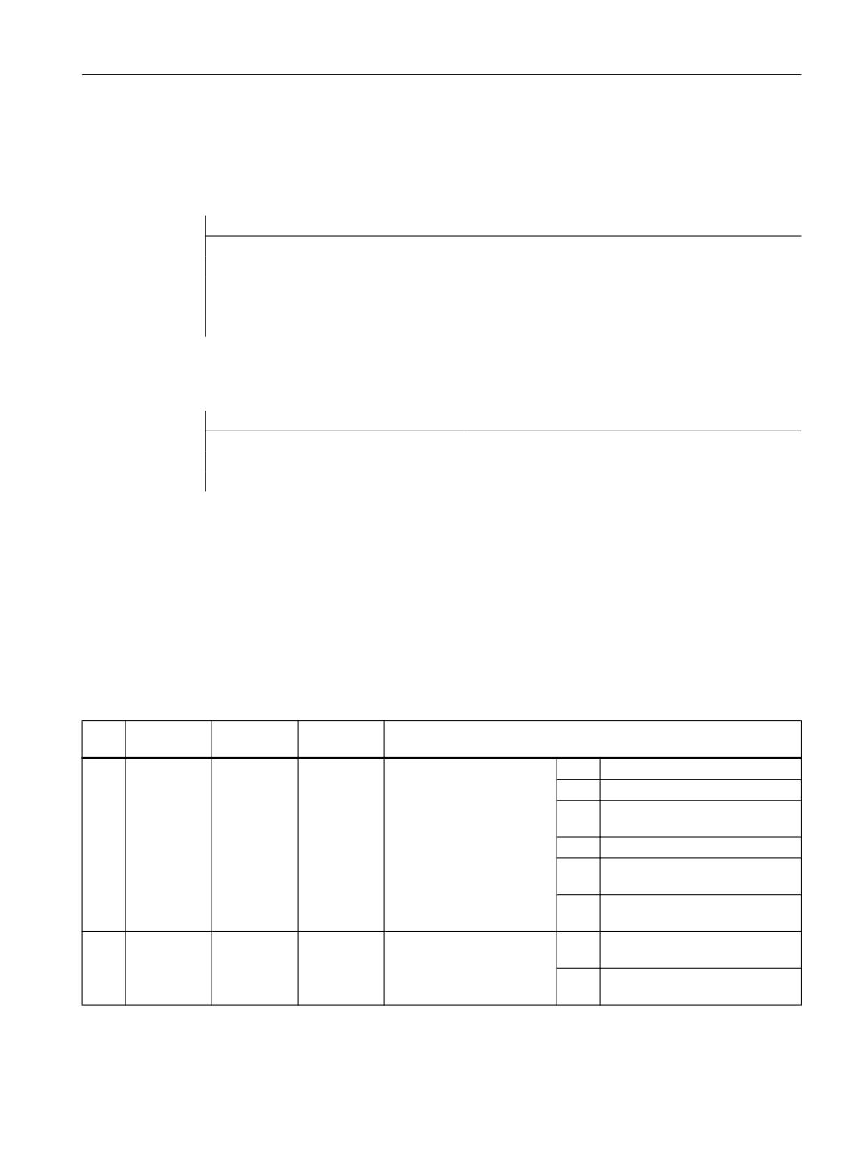
CYCLE800 - swivel plane / swivel tool / align tool
Syntax
CYCLE800(<_FR>, <_TC>, <_ST>, <_MODE>, <_X0>, <_Y0>, <_Z0>, <_A>,
<_B>, <_C>, <_X1>, <_Y1>, <_Z1>, <_DIR>, <_FR_I>, <_DMODE>)
Parameters
No.
Parameter
Parameter
Data type
Meaning
mask
internal
1
<_FR>
INT
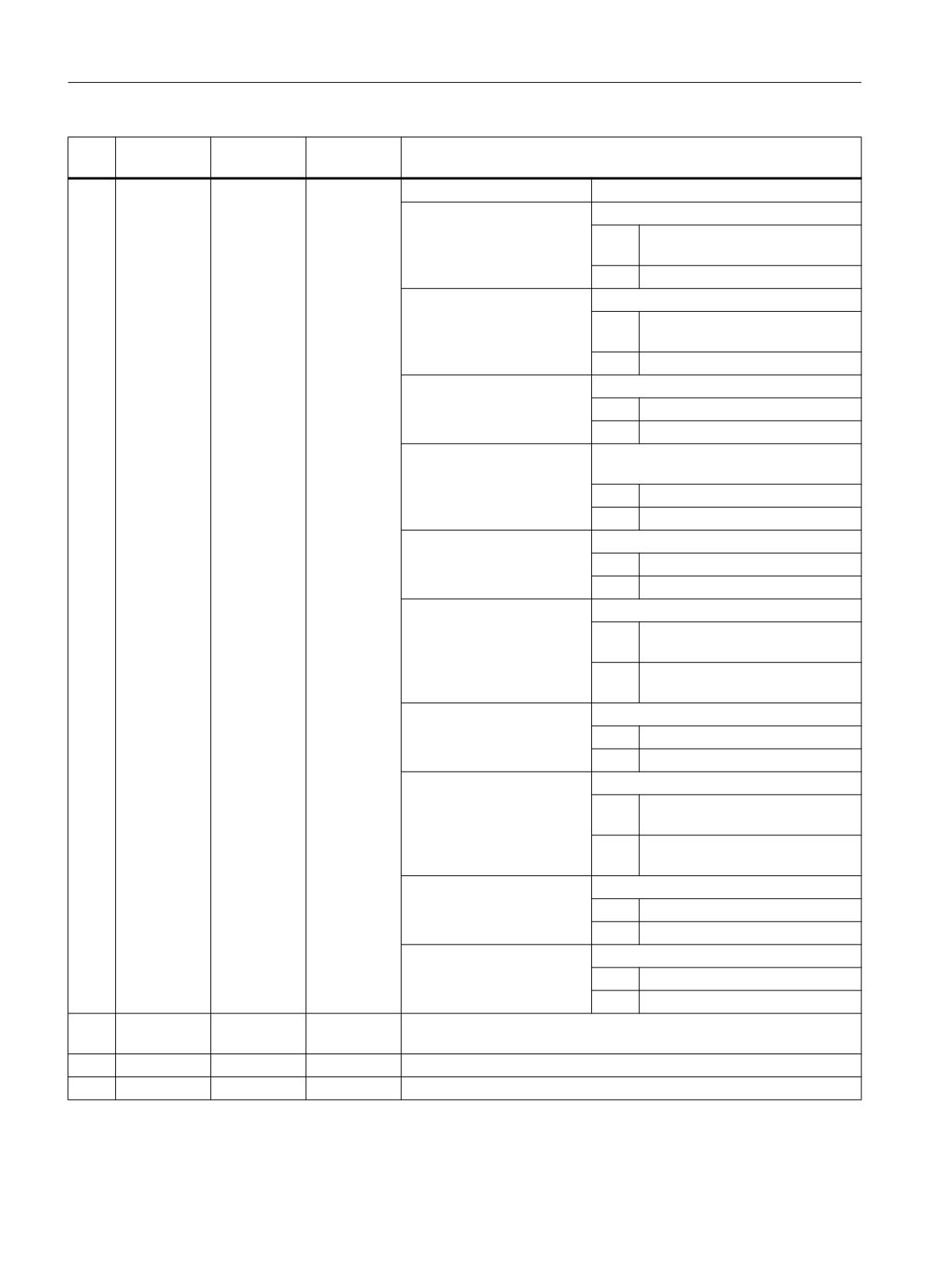
Retraction mode:
0 =
No retraction
1 =
Retraction machine axis Z
2 =
Retraction machine axis Z and
then XY
3 =
Reserved
4 =
Maximum retraction in tool direc-
tion
5 =
Incremental retraction in tool di-
rection
2
<_TC>
STRING[32]
Name of swivel data block:
""
"" (no name) if only one swivel
data block exists
"0"
Deselect swivel data block (de-
lete the swivel frames)
Job Planning
Programming Manual, 12/2018, A5E40869460B AB
765
Programming cycles externally
20.1 Technology cycles
No.
Parameter
Parameter
Data type
Meaning
mask
internal
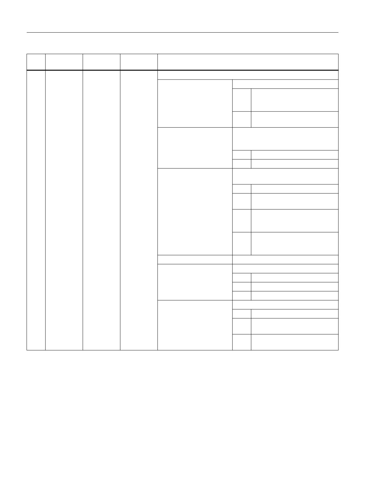
3
<_ST>
INT
Status transformations
UNITS:
0 =
New, swivel level is deleted and
recalculated using the current pa-
rameters
1 =
Additive, swivel level is added to
active swivel level
TENS:
Track tool tip yes/no (only active when
the SWIVEL function is created in the
commissionig)
0 =
Do not track tool tip
1 =
Track tool tip (TRAORI)
HUNDREDS:
Approach/align tool (function is shown in
tool swivel screen form)
0 =
Do not approach tool
1 =
Approach tool (preferably radial
mill)
2 =
Align turning tool (when B axis
kinematic is set up for milling in
commissioning swiveling)
3 =
Align milling tool (when B axis
kinematic is set up for milling in
commissioning swiveling)
THOUSANDS:
Internal "Swiveling in JOG" parameter
TEN THOUSANDS:
See direction parameter <_DIR>
0 =
Swivel "Yes"
1 =
Swivel "No", "Minus" direction3)
2 =
Swivel "No", "Plus" direction3)
HUNDRED THOUSANDS:
See direction parameter <_DIR>
0 =
Compatibility
1 =
Direction selection "Minus" opti-
mized (only for user interface) 4)
2 =
Direction selection "Plus" opti-
mized (only for user interface) 4)
Job Planning
766
Programming Manual, 12/2018, A5E40869460B AB
Programming cycles externally
20.1 Technology cycles
No.
Parameter
Parameter
Data type
Meaning
mask
internal
5)
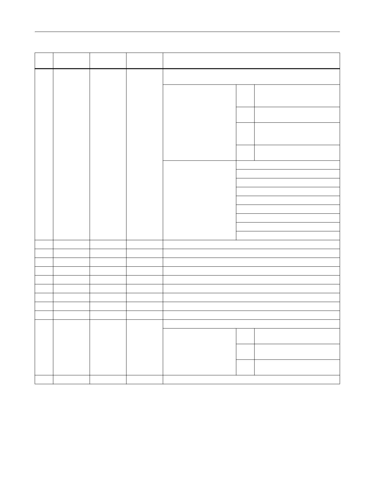
4
<_MODE>
INT
Swivel mode: Evaluation of swivel angle and swivel sequence (bit-co-
ded)
Bit: 7 6
0 0:
Swivel angle axis-by-axis -> see
parameters <_A>, <_B>,
<_C>
0 1:
Solid angle -> see parameters
<_A>, <_B> 1)
1 0:
Projection angle -> see parame-
ters <_A>, <_B>,
<_C> 1)
1 1:
Direct rotary axis swivel mode ->
see parameters <_A>, <_B> 1)
Bit: 5 4 3 2 1 0
x x x x 0 1 1st rotation _A around X
(these do not apply to solid
x x x x 1 0 1st rotation _A around Y
angles)
x x x x 1 1 1st rotation _A around Z
x x 0 1 x x 2nd rotation _B around X
x x 1 0 x x 2nd rotation _B around Y
x x 1 1 x x 2nd rotation _B around Z
0 1 x x x x 3rd rotation _C around X
1 0 x x x x 3rd rotation _C around Y
1 1 x x x x 3rd rotation _C around Z
5
X0
<_X0>
REAL
Reference point X prior to rotation
6
Y0
<_Y0>
REAL
Reference point Y prior to rotation
7
Z0
<_Z0>
REAL
Reference point Z prior to rotation
8
X(A)
<_A>
REAL
1st rotation acc. to setting in parameter <_MODE>
9
Y(B)
<_B>
REAL
2nd rotation acc. to setting in parameter <_MODE>
10
Z(C)
<_C>
REAL
3rd rotation acc. to setting in parameter <_MODE>
11
X1
<_X1>
REAL
Reference point X after rotation
12
Y1
<_Y1>
REAL
Reference point Y after rotation
13
Z1
<_Z1>
REAL
Reference point Z after rotation
14
- or +
<_DIR>
INT
Initiate travel of rotary axes (default = -1!)
-1 =
Position at smaller value of rotary
axis 1 or 2 2)
+1 =
Position at larger value of rotary
axis 1 or 2 2)
0 =
Do not swivel (merely calculate
swivel frame) 1) 3)
15
FR
<_FR_I>
REAL
Value (inc) of retraction in tool direction incremental
Job Planning
Programming Manual, 12/2018, A5E40869460B AB
767
Programming cycles externally
20.1 Technology cycles
No.
Parameter
Parameter
Data type
Meaning
mask
internal
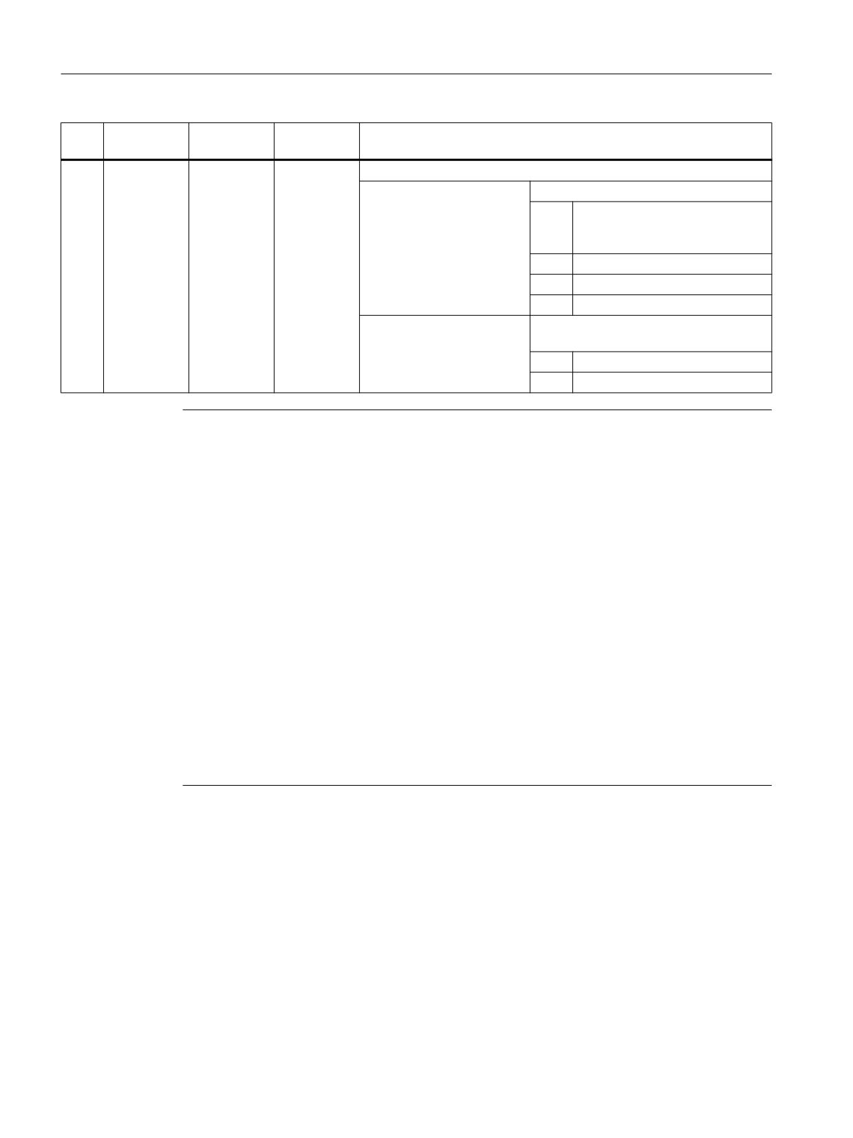
16
<_DMODE>
INT
Display mode
UNITS:
Machining plane G17/G18/G19
0 =
Compatibility, the plane effective
before the cycle call remains ac-
tive
1 =
G17 (only active in the cycle)
2 =
G18 (only active in the cycle)
3 =
G19 (only active in the cycle)
TENS:
Representation of the beta value during
align tool
0 =
Value
1 =
Arrow
Note
If the following transfer parameters are programmed indirectly (as parameters), the screen
form is not reset: <_FR>, <_ST>, <_TC>, <_MODE>, <_DIR>
1) Can be selected if the SWIVEL function is created in the commissioning
2) Can be selected if direction reference to rotary axis 1 or 2 is set in IBN SWIVEL
If direction reference is "No" there is no selection field
3) Swivel selection "No" can be grayed out SD 55221 Bit 0
Swivel "No", "Minus" direction corresponds to <_DIR> = 0 and _ST TEN THOUSANDS = 1
Swivel "No", "Plus" direction corresponds to <_DIR> = 0 and _ST TEN THOUSANDS = 2
4) The direction selection for rotary axis 1 or 2 also occurs if the rotary axis with the direction
reference is in the pole position (position value equals zero).
5) Coding example: Axis-by-axis rotation, rotary sequence ZYX
Binary: 00011011 Decimal: 27
The axis identifiers XYZ correspond to the geometry axes of the NC channel. Individual
rotations around the XYZ axes are permissible. For example, rotary sequence around ZXZ is
not permitted in one call of CYCLE800
20.1.35
CYCLE801 - grid or frame position pattern
Syntax
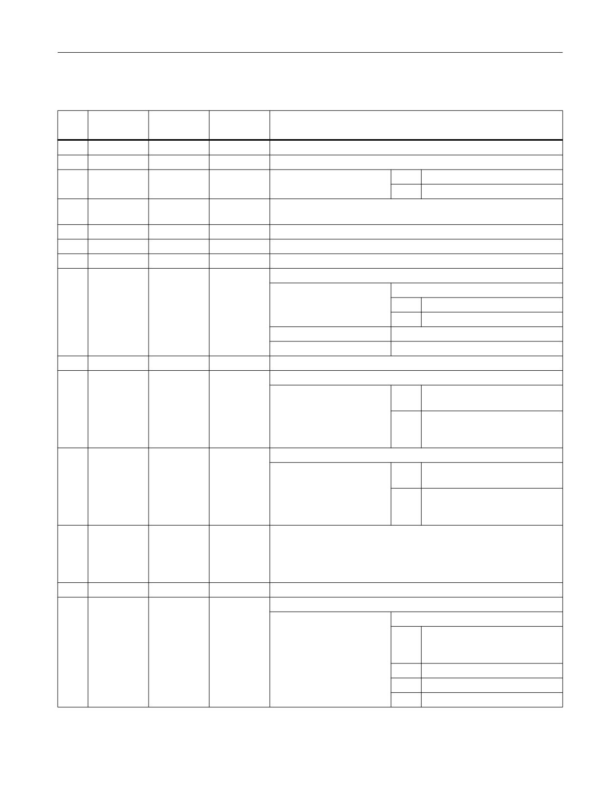
CYCLE801(<_SPCA>, <_SPCO>, <_STA>, <_DIS1>, <_DIS2>, <_NUM1>,
<_NUM2>, <_VARI>, <_UMODE>, <_ANG1>, <_ANG2>, <_HIDE>, <_NSP>,
<_DMODE>)
Job Planning
768
Programming Manual, 12/2018, A5E40869460B AB
Programming cycles externally
20.1 Technology cycles
Parameters
No.
Parameter
Parameters
Data type
Meaning
mask
internal
1
X0
<_SPCA>
REAL
Reference point for position pattern (grid/frame) along the 1st axis (abs)
2
Y0
<_SPCO>
REAL
Reference point for position pattern (grid/frame) along the 2nd axis (abs)
3
α0
<_STA>
REAL
Basic angle of rotation
< 0 =
Clockwise rotation
(angle to 1st axis)
> 0 =
Counterclockwise rotation
4
L1
<_DIS1>
REAL
Distance between columns (position distance from the 1st axis, enter
without sign)
5
L2
<_DIS2>
REAL
Distance between rows (distance from the 2nd axis, enter without sign)
6
N1
<_NUM1>
INT
Number of columns
7
N2
<_NUM2>
INT
Number of rows
8
<_VARI>
INT
Machining type
UNITS:
Position pattern
0 =
Grid
1 =
Frame
TENS:
Reserved
HUNDREDS:
Reserved
9
<_UMODE>
INT
Reserved
10
αX
<_ANG1>
REAL
Shear angle to 1st axis (lines inclined in relation to the 1st axis)
< 0 =
Clockwise measurement
(0 to -90 degrees)
> 0 =
Counter-clockwise measure-
ment
(0 to 90 degrees)
11
αY
<_ANG2>
REAL
Shear angle to 2nd axis (columns inclined in relation to the 2nd axis)
< 0 =
Clockwise measurement
(0 to -90 degrees)
> 0 =
Counter-clockwise measure-
ment
(0 to 90 degrees)
12
<_HIDE>
STRING
Hidden positions
[200]
● Max. 198 characters
● Specification of consecutive position numbers, e.g. "1,3" (positions
1 and 3 are not executed)
13
<_NSP>
INT
Reserved
14
<_DMODE>
INT
Display mode
UNITS:
Machining plane G17/G18/G19
0 =
Compatibility, the plane effective
before the cycle call remains ac-
tive
1 =
G17 (only active in the cycle)
2 =
G18 (only active in the cycle)
3 =
G19 (only active in the cycle)
Job Planning
Programming Manual, 12/2018, A5E40869460B AB
769
Programming cycles externally
20.1 Technology cycles
20.1.36
CYCLE802 - arbitrary positions
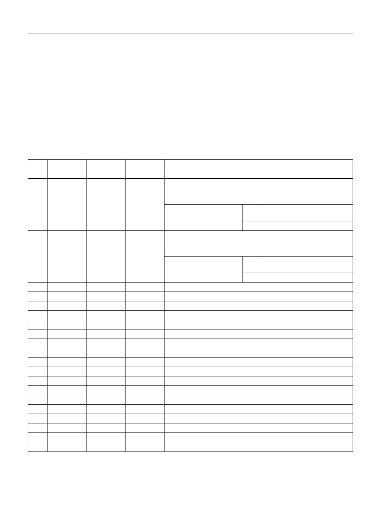
Syntax
CYCLE802(<_XA>, <_YA>, <_X0>, <_Y0>, <_X1>, <_Y1>, <_X2>, <_Y2>,
<_X3>, <_Y3>, <_X4>, <_Y4>, <_X5>, <_Y5>, <_X6>, <_Y6>, <_X7>, <_Y7>,
<_X8>, <_Y8>, <_VARI>, <_UMODE>, <_DMODE>, <S_ABA>, <S_AB0>,
<S_AB1>, <S_AB2>, <S_AB3>, <S_AB4>, <S_AB5>, <S_AB6>, <S_AB7>,
<S_AB8>)
Parameters
No.
Parameter
Parameters
Data type
Meaning
mask
internal
1
<_XA>
INT
Alternatives for all X positions (9-digit decimal value)
Number of digits: 876543210 (digit position corresponds to drilling po-
sition Xn)
Position value:
1 =
Absolute (1st programmed posi-
tion is always absolute)
2 =
Incremental
2
<_YA>
INT
Alternatives for all Y positions (9-digit decimal value)
Number of digits: 876543210 (digit position corresponds to drilling po-
sition Yn)
Position value:
1 =
Absolute (1st programmed posi-
tion is always absolute)
2 =
Incremental
3
X0
<_X0>
REAL
1. Position X
4
Y0
<_Y0>
REAL
1. Position Y
5
X1
<_X1>
REAL
2. Position X
6
Y1
<_Y1>
REAL
2. Position Y
7
X2
<_X2>
REAL
3. Position X
8
Y2
<_Y2>
REAL
3. Position Y
9
X3
<_X3>
REAL
4. Position X
10
Y3
<_Y3>
REAL
4. Position Y
11
X4
<_X4>
REAL
5. Position X
12
Y4
<_Y4>
REAL
5. Position Y
13
X5
<_X5>
REAL
6. Position X
14
Y5
<_Y5>
REAL
6. Position Y
15
X6
<_X6>
REAL
7. Position X
16
Y6
<_Y6>
REAL
7. Position Y
17
X7
<_X7>
REAL
8. Position X
18
Y7
<_Y7>
REAL
8. Position Y
19
X8
<_X8>
REAL
9. Position X
20
Y8
<_Y8>
REAL
9. Position Y
Job Planning
770
Programming Manual, 12/2018, A5E40869460B AB
Programming cycles externally
20.1 Technology cycles
No.
Parameter
Parameters
Data type
Meaning
mask
internal
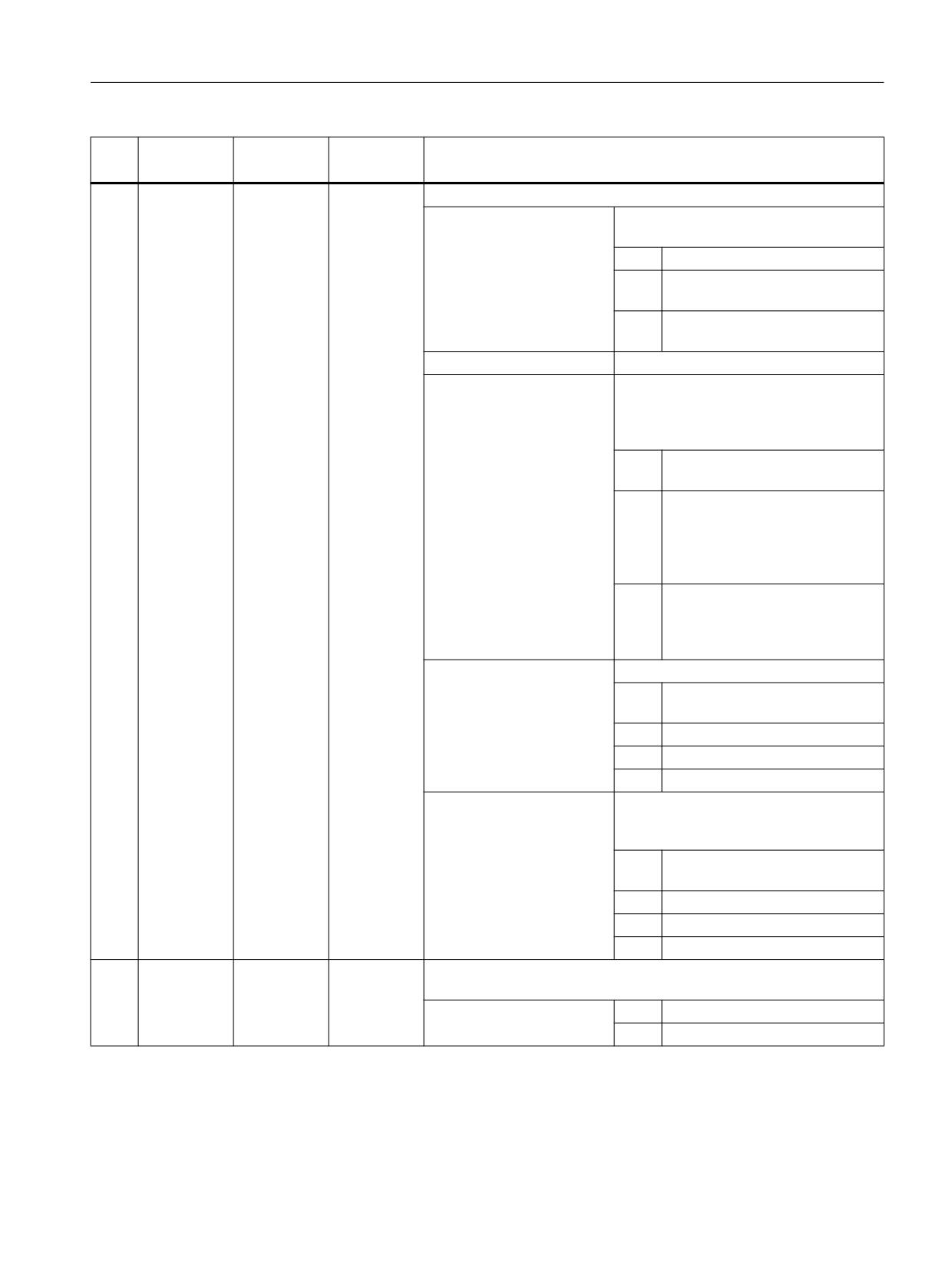
21
<_VARI>
INT
Machining
HUNDREDS:
(Only for call from Jobshop) (At present
only 0 and 2 evaluated)
0 =
Do not clamp spindle
1 =
Only clamp spindle for vertical in-
sertion with G00 or G01
2 =
Clamp spindle during the entire
machining operation
THOUSANDS:
Reserved
TEN THOUSANDS:
Position pattern with/without rotary axis
- axis combination
(with <_VARI> HUNDRED THOU-
SANDS)
0 =
XY (only XY without rotary axis,
compatibility)
1 =
X,Y or Z and rotary axis:
XA, YB, ZC
(1 rotary axis with geometry axis
around which the rotary axis ro-
tates)
2 =
XY and rotary axis:
XYA, XYB, XYC
(1 rotary axis with 1st and 2nd
geometry axis, without TRACYL)
HUNDRED THOUSANDS:
Rotary axis
0 =
Without rotary axis
(only XY, compatibility)
1 =
A axis (rotary axis around X)
2 =
B axis (rotary axis around Y)
3 =
C axis (rotary axis around Z)
TEN MILLIONS + ONE MIL-
Position pattern with rotary axis - offset
LION:
(for several rotary axes around the same
axis; if index too large, then 1st axis)
00 =
1st A, B or C axis or for compati-
bility
01 =
2nd A, B or C axis
19 =
20th A, B or C axis
22
<_UMODE>
INT
Selection of the spindle to be clamped: (Only for call from Jobshop)
(Call of user cycle CUST_TECHCYC)
3 =
Clamp/release main spindle
23 =
Clamp/release counterspindle
Job Planning
Programming Manual, 12/2018, A5E40869460B AB
771
Programming cycles externally
20.1 Technology cycles
No.
Parameter
Parameters
Data type
Meaning
mask
internal
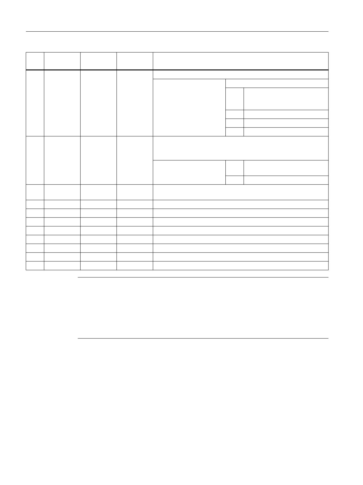
23
<_DMODE>
INT
Display mode
UNITS:
Machining plane G17/G18/G19
0 =
Compatibility, the plane effective
before the cycle call remains ac-
tive
1 =
G17 (only active in the cycle)
2 =
G18 (only active in the cycle)
3 =
G19 (only active in the cycle)
24
<S_ABA>
INT
Alternatives for all AB positions (9-digit decimal value)
Number of digits: 876543210 (digit position corresponds to position
ABn)
Position value:
1 =
Absolute (1st programmed posi-
tion is always absolute)
2 =
Incremental
25
A0
<S_AB0>
REAL
1st rotary axis position for position pattern with rotary axis (in conjunc-
tion with <_VARI>))
26
A1
<S_AB1>
REAL
2nd rotary axis position for position pattern with rotary axis
27
A2
<S_AB2>
REAL
3rd rotary axis position for position pattern with rotary axis
28
A3
<S_AB3>
REAL
4th rotary axis position for position pattern with rotary axis
29
A4
<S_AB4>
REAL
5th rotary axis position for position pattern with rotary axis
30
A5
<S_AB5>
REAL
6th rotary axis position for position pattern with rotary axis
31
A6
<S_AB6>
REAL
7th rotary axis position for position pattern with rotary axis
32
A7
<S_AB7>
REAL
8th rotary axis position for position pattern with rotary axis
33
A8
<S_AB8>
REAL
9th rotary axis position for position pattern with rotary axis
Note
Positions that are not required for parameters X1/Y1/A1 to X8/Y8/A8 can be ignored. The
alternative values for <_XA>, <_YA> and <S_ABA>, however, must be provided in full for all
9 positions.
For position pattern XA, YB or ZC (a geometry axis and rotary axis), the axis of the machining
plane that is not traversed via the position pattern (Y for G17 and XA) must be positioned
before the cycle call.
20.1.37
CYCLE830 - deep-hole drilling 2
Syntax
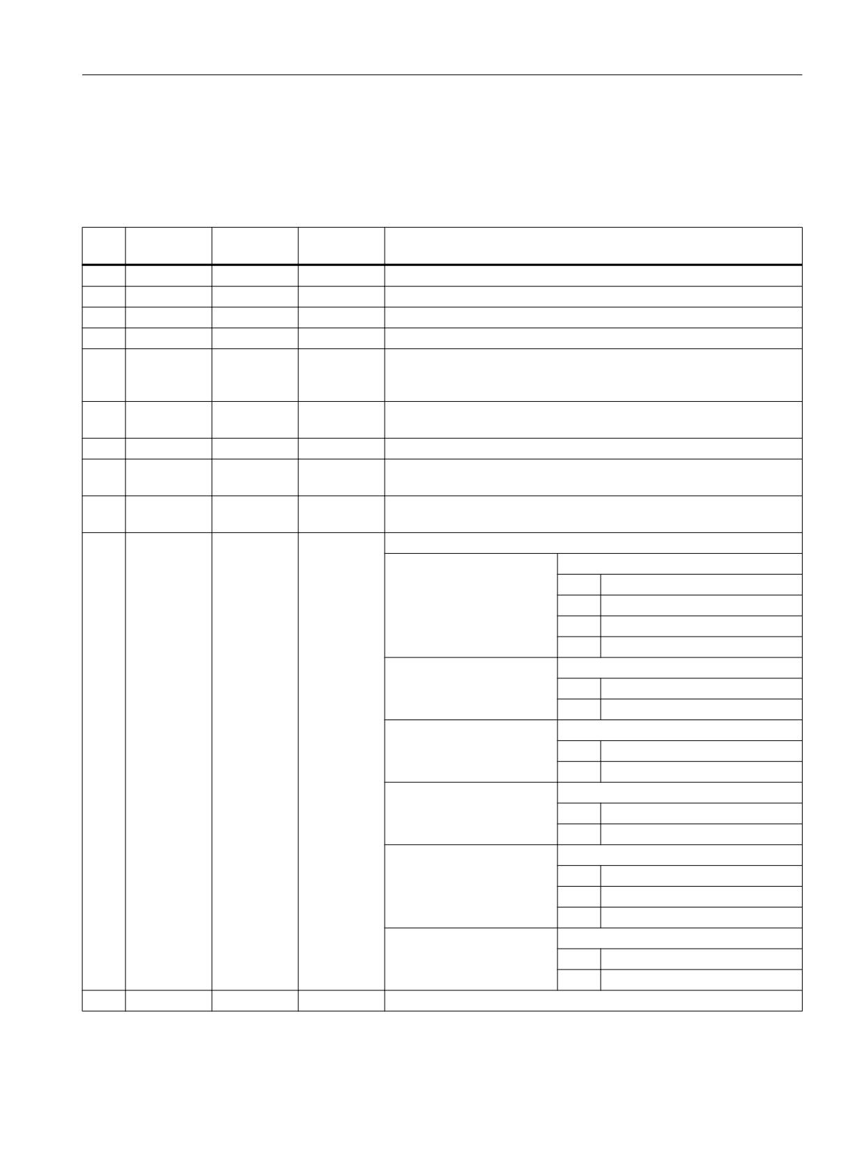
CYCLE830(<RTP>, <RFP>, <SDIS>, <_DP>, <FDEP>, <_DAM>, <DTB>, <DTS>,
<FRF>, <VARI>, <_MDEP>, <_VRT>, <_DTD>, <_DIS1>, <S_FP>, <S_SDAC2>,
<S_SV2>, <S_FB>, <_SDAC>, <_SV1>, <S_SPOS>, <S_ZA>, <S_FA>, <S_ZP>,
<S_FS>, <S_ZS1>, <S_ZS2>, <S_N>, <S_ZD>, <S_FD>, <S_FR>, <S_SDAC3>,
Job Planning
772
Programming Manual, 12/2018, A5E40869460B AB
Programming cycles externally
20.1 Technology cycles
<S_SV3>, <S_CON>, <S_COFF>, <_GMODE>, <_DMODE>, <_AMODE>,
<S_AMODE2>, <S_AMODE3>, <S_ZPV>)
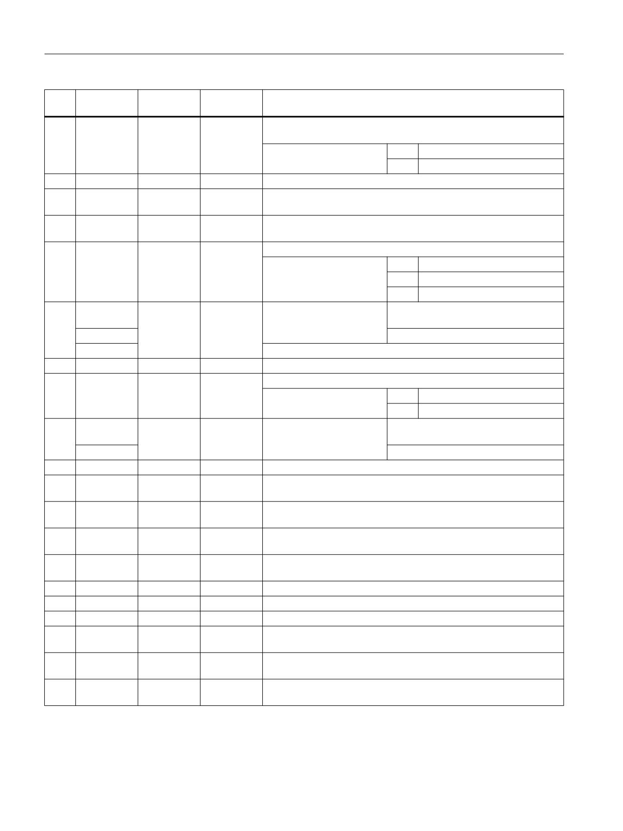
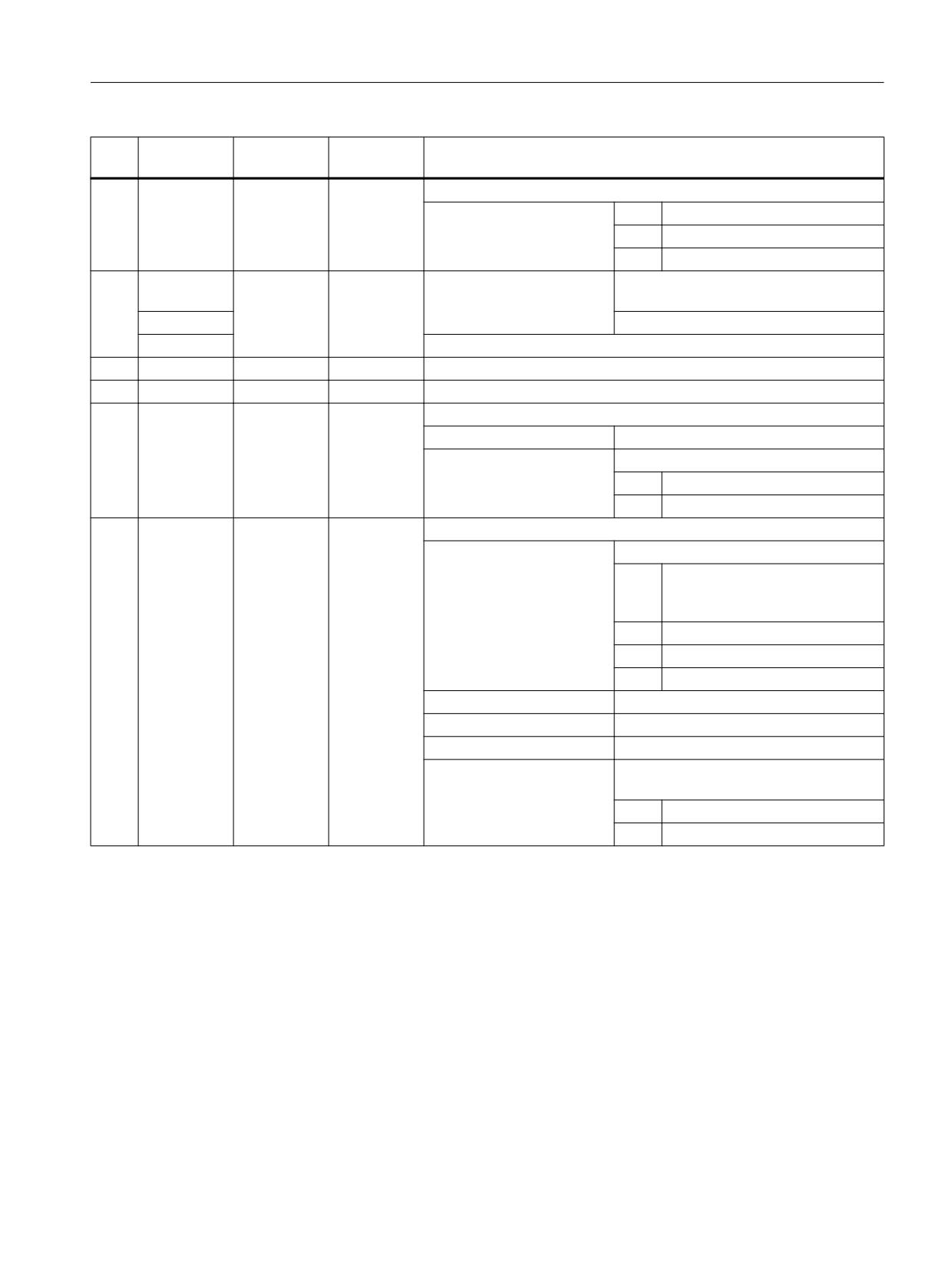
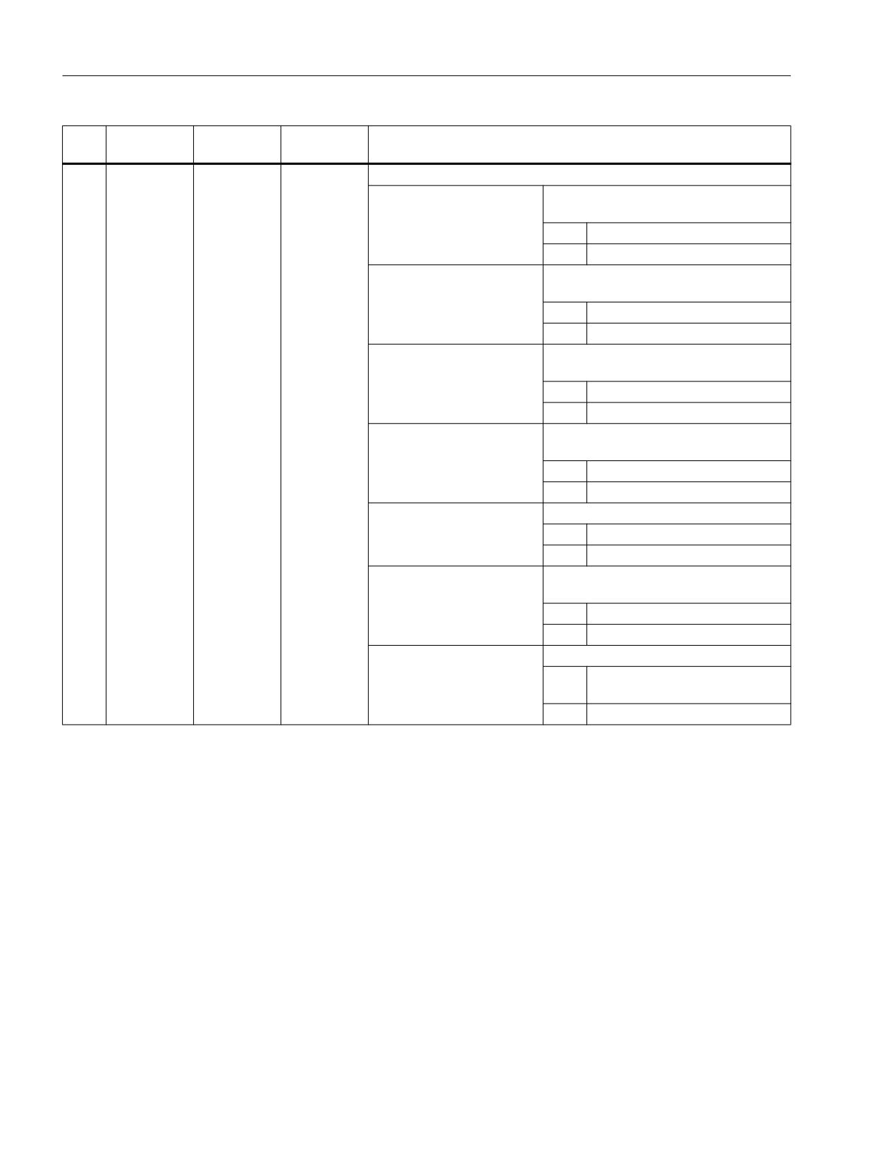
Parameters
No.
Parameter
Parameter
Data type
Meaning
mask
internal
1
RP
<RTP>
REAL
Retraction plane (abs)
2
Z0
<RFP>
REAL
Reference point (abs)
3
SC
<SDIS>
REAL
Safety clearance (to be added to reference point, without sign)
4
Z1
<_DP>
REAL
Final drilling depth abs/inc (see <_AMODE>UNITS)
5
D
<FDEP>
REAL
1st drilling depth for the absolute or incremental chip breaking/removal
in relation to the reference point with/without predrilling or in relation to
pilot hole depth (see <_AMODE> TEN THOUSANDS)
6
DF
<_DAM>
REAL
Absolute value / percentage for each additional infeed, degression ab-
solute value / percentage (see <_AMODE> HUNDRED THOUSANDS)
7
DTB
<DTB>
REAL
Dwell time at each drilling depth (see <_AMODE> TENS)
8
DTS
<DTS>
REAL
Dwell time during chip removal at starting point (see <_AMODE> HUN-
DREDS)
9
FD1
<FRF>
REAL
Percentage for the feedrate for the first infeed (see <_AMODE> TEN
MILLION)
10
<VARI>
INT
Machining
UNITS:
Chip breaking / swarf removal
0 =
In one cut
1 =
Chip breaking
2 =
Swarf removal
3 =
Chip breaking and swarf removal
TENS:
Retraction during swarf removal
0 =
To pilot hole depth
1 =
To safety clearance
HUNDREDS:
Soft first cut
0 =
No
1 =
Yes
THOUSANDS:
Through drilling
0 =
No
1 =
Yes
TEN THOUSANDS:
Predrilling / pilot hole
0 =
Without predrilling
1 =
With predrilling
2 =
With pilot hole
HUNDRED THOUSANDS:
Retraction
0 =
To pilot hole depth
1 =
To retraction plane
11
V1
<_MDEP>
REAL
Minimum incremental infeed (only for degression percentage)
Job Planning
Programming Manual, 12/2018, A5E40869460B AB
773
Programming cycles externally
20.1 Technology cycles
No.
Parameter
Parameter
Data type
Meaning
mask
internal
12
V2
<_VRT>
REAL
Retraction distance after each incremental machining step (for chip
breaking only)
0 =
Default value 1 mm
> 0 =
Variable retraction distance
13
DT
<_DTD>
REAL
Dwell time at final drilling depth (see <_AMODE> THOUSANDS)
14
V3
<_DIS1>
REAL
Incremental limit distance for chip removal only (see <_AMODE> ONE-
MILLION)
15
FP
<S_FP>
REAL
Feedrate for travel into the pilot hole as value or in % (in conjunction
with <S_AMODE2> HUNDREDS)
16
<S_SDAC2>
INT
Direction of spindle rotation during approach
3 =
M3
4 =
M4
5 =
M5 (default)
17
SP
<S_SV2>
REAL
Approach with
constant spindle speed (see
<S_AMODE2> TEN MILLION)
V4
constant cutting rate
Spindle speed in % of the drilling speed
18
F
<S_FB>
REAL
Drilling feedrate (see <S_AMODE2> UNITS)
19
<_SDAC>
REAL
Direction of spindle rotation during drilling
3 =
M3
4 =
M4
20
S
<_SV1>
REAL
Drilling with
constant spindle speed (see
<S_AMODE2> ONE MILLION)
V5
constant cutting rate
21
SPOS
<S_SPOS>
REAL
Spindle position, only if approach with M5
22
ZA
<S_ZA>
REAL
Incremental predrilling depth in relation to reference point or absolute
(see <S_AMODE3> UNITS)
23
FA
<S_FA>
REAL
Predrilling feedrate as value or in % (in conjunction with <S_AMODE2>
TENS)
24
ZP
<S_ZP>
REAL
Incremental pilot hole in relation to reference point or absolute or factor
of the hole diameter (see <S_AMODE3> TENS)
25
FS
<S_FS>
REAL
First cut feedrate as value or in % (in conjunction with <S_AMODE2>
THOUSANDS)
26
ZS1
<S_ZS1>
REAL
Depth of each first cut with constant feedrate (inc)
27
ZS2
<S_ZS2>
REAL
Depth of each first cut for feedrate increase (inc)
28
N
<S_N>
INT
Number of chip breaking strokes before each chip removal
29
ZD
<S_ZD>
REAL
Incremental remaining drilling depth in relation to final drilling depth or
absolute (see <S_AMODE3> HUNDREDS)
30
FD
<S_FD>
REAL
Remaining drilling feedrate as value or in % (in conjunction with
<S_AMODE2> TEN THOUSANDS)
31
FR
<S_FR>
REAL
Retraction feedrate (in conjunction with <S_AMODE2> HUNDRED
THOUSANDS)
Job Planning
774
Programming Manual, 12/2018, A5E40869460B AB
Programming cycles externally
20.1 Technology cycles
No.
Parameter
Parameter
Data type
Meaning
mask
internal
32
<S_SDAC3>
INT
Direction of spindle rotation during retraction
3 =
M3
4 =
M4
5 =
M5
33
SR
<S_SV3>
REAL
Retraction with
constant spindle speed (see
<S_AMODE2> HUNDRED MILLION)
V6
constant cutting rate
Spindle speed in % of the drilling speed
34
Coolant on
<S_CON>
STRING[10]
Coolant on, M command or subprogram call
35
Coolant off
<S_COFF>
STRING[10]
Coolant off, M command or subprogram call
36
<_GMODE>
INT
Geometrical mode (evaluation of programmed geometrical data)
UNITS:
Reserved
TENS:
Drilling depth with respect to tip/shank
0 =
Tip
1 =
Shank
37
<_DMODE>
INT
Display mode
UNITS:
Machining plane G17/G18/G19
0 =
Compatibility, the plane effective
before the cycle call remains ac-
tive
1 =
G17 (only active in the cycle)
2 =
G18 (only active in the cycle)
3 =
G19 (only active in the cycle)
TENS:
Reserved
HUNDREDS:
Reserved
THOUSANDS:
Reserved
TEN THOUSANDS:
Technology scaling in cycle screen
forms (Page 821)
0 =
Input: Complete
1 =
Input: Basic
Job Planning
Programming Manual, 12/2018, A5E40869460B AB
775
Programming cycles externally
20.1 Technology cycles
No.
Parameter
Parameter
Data type
Meaning
mask
internal
38
<_AMODE>
INT
Alternative mode 1
UNITS:
Drilling depth = Final drilling depth Z1
abs/inc
0 =
Incremental
1 =
Absolute
TENS:
Dwell time at each drilling depth DTB in
seconds/revolutions
0 =
In seconds
1 =
In revolutions
HUNDREDS:
Dwell time for chip removal DTS in sec-
onds/revolutions
0 =
In seconds
1 =
In revolutions
THOUSANDS:
Dwell time at final drilling depth DT in
seconds/revolutions
0 =
In seconds
1 =
In revolutions
TEN THOUSANDS:
1st drilling depth D abs/inc
0 =
Incremental
1 =
Absolute
HUNDRED THOUSANDS:
Absolute value / percentage DF for each
additional infeed (degression)
0 =
Absolute value
1 =
Percentage (0.001 to 100%)
ONE MILLION:
Limit distance V3 automatic/manual
0 =
Automatic (calculated in the cy-
cle)
1 =
Manual (programmed value)
Job Planning
776
Programming Manual, 12/2018, A5E40869460B AB
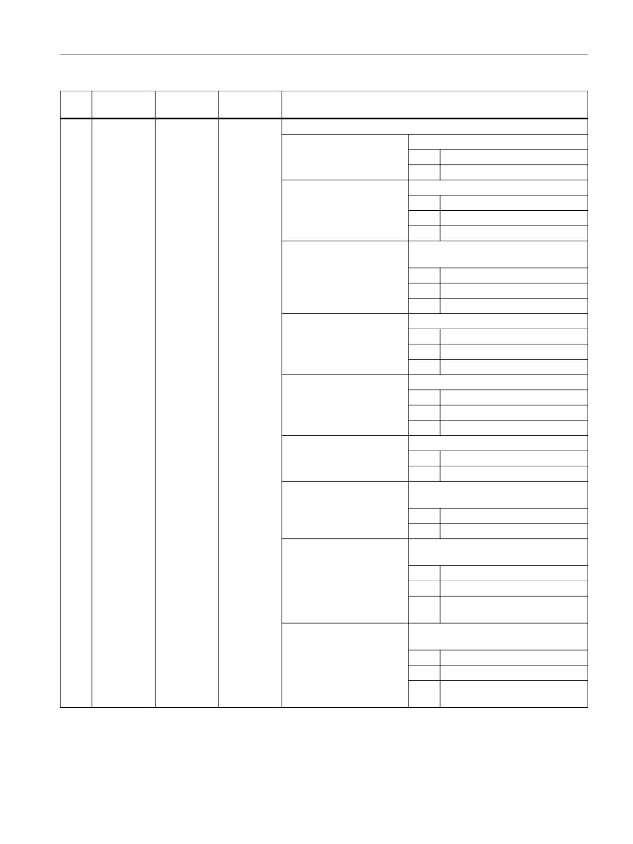
Programming cycles externally
20.1 Technology cycles
No.
Parameter
Parameter
Data type
Meaning
mask
internal
39
<S_AMODE2
INT
Alternative mode 2
>
UNITS:
UNITS: Drilling feedrate F
0 =
F/min
1 =
F/rev
TENS:
Evaluation of predrilling feedrate FA
0 =
As % of drilling feedrate
1 =
F/min
2 =
F/rev
HUNDREDS:
Evaluation of feedrate for travel into pilot
hole FP
0 =
As % of drilling feedrate
1 =
F/min
2 =
F/rev
THOUSANDS:
Evaluation of first cut feedrate FS
0 =
As % of drilling feedrate
1 =
F/min
2 =
F/rev
TEN THOUSANDS:
Evaluation of through-drilling feedrate FD
0 =
As % of drilling feedrate
1 =
F/min
2 =
F/rev
HUNDRED THOUSANDS:
Retraction feedrate FR
0 =
F/min
1 =
Rapid traverse
ONE MILLION:
Drilling - spindle speed / cutting rate (S/
V5)
0 =
Constant spindle speed
1 =
Constant cutting rate
TEN MILLIONS:
Approach with spindle speed / cutting
rate (SP/V4)
0 =
Constant spindle speed
1 =
Constant cutting rate
2 =
Spindle speed in % of the drilling
speed
HUNDRED MILLIONS:
Retraction - spindle speed / cutting rate
(SR/V6)
0 =
Constant spindle speed
1 =
Constant cutting rate
2 =
Spindle speed in % of the drilling
speed
Job Planning
Programming Manual, 12/2018, A5E40869460B AB
777
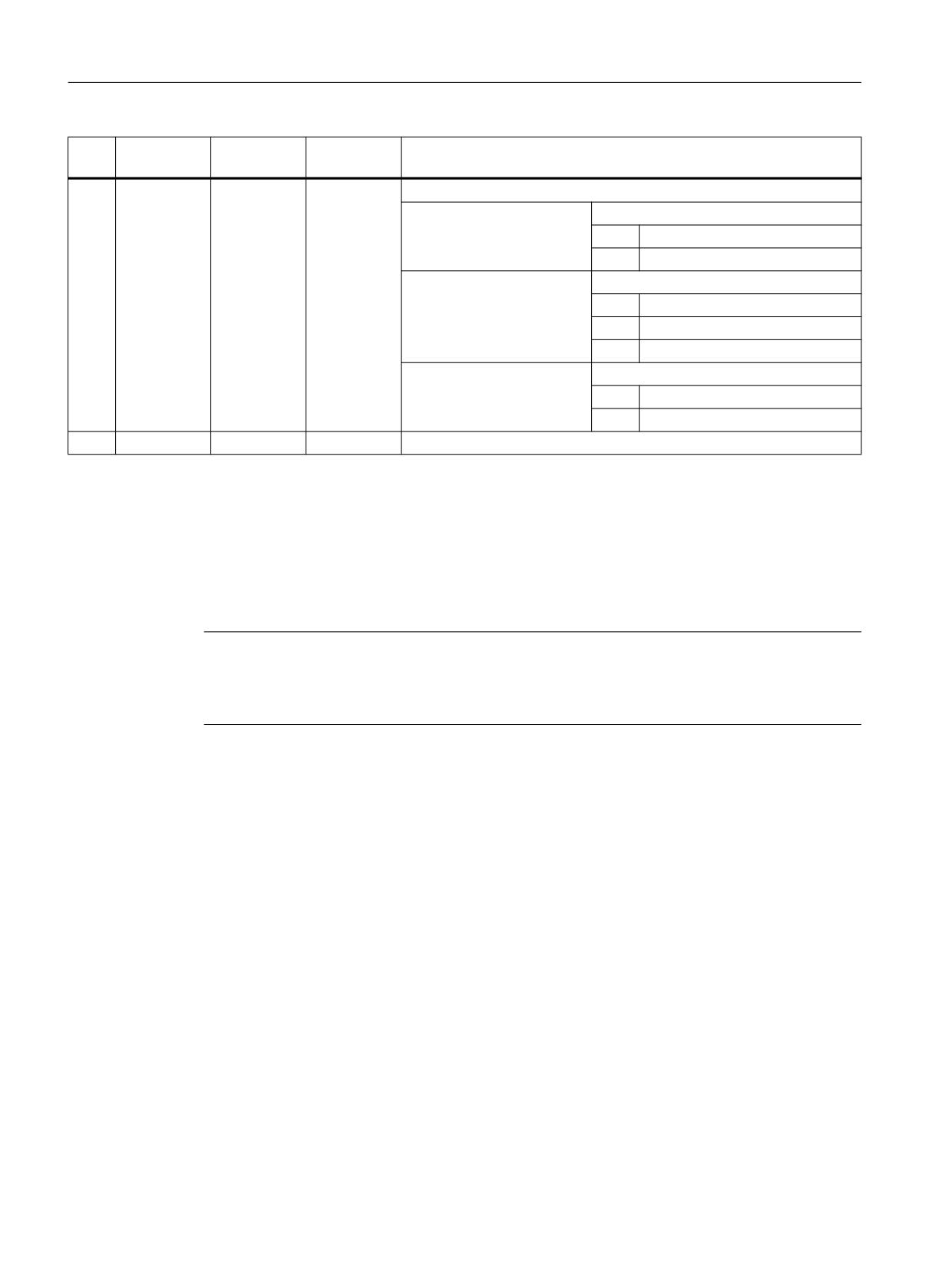
Programming cycles externally
20.1 Technology cycles
No.
Parameter
Parameter
Data type
Meaning
mask
internal
40
<S_AMODE3
INT
Alternative mode 3
>
UNITS:
Drilling depth ZA abs/inc
0 =
Incremental
1 =
Absolute
TENS:
Depth of the pilot hole ZP
0 =
Incremental
1 =
Absolute
2 =
Factor of the hole diameter
HUNDREDS:
Remaining drilling depth ZD abs/inc
0 =
Incremental
1 =
Absolute
41
ZPV
<S_ZPV>
REAL
Incremental limit distance from pilot hole depth
20.1.38
CYCLE832 - High-Speed Settings
Syntax
CYCLE832(<S_TOL>, <S_TOLM>, <S_OTOL>)
Note
CYCLE832 does not relieve the machine manufacturer from optimization tasks that are
necessary when commissioning the machine. This involves the optimization of the axes
involved in the machining process and NCU settings (precontrol, jerk limiting, etc.).
Job Planning
778
Programming Manual, 12/2018, A5E40869460B AB
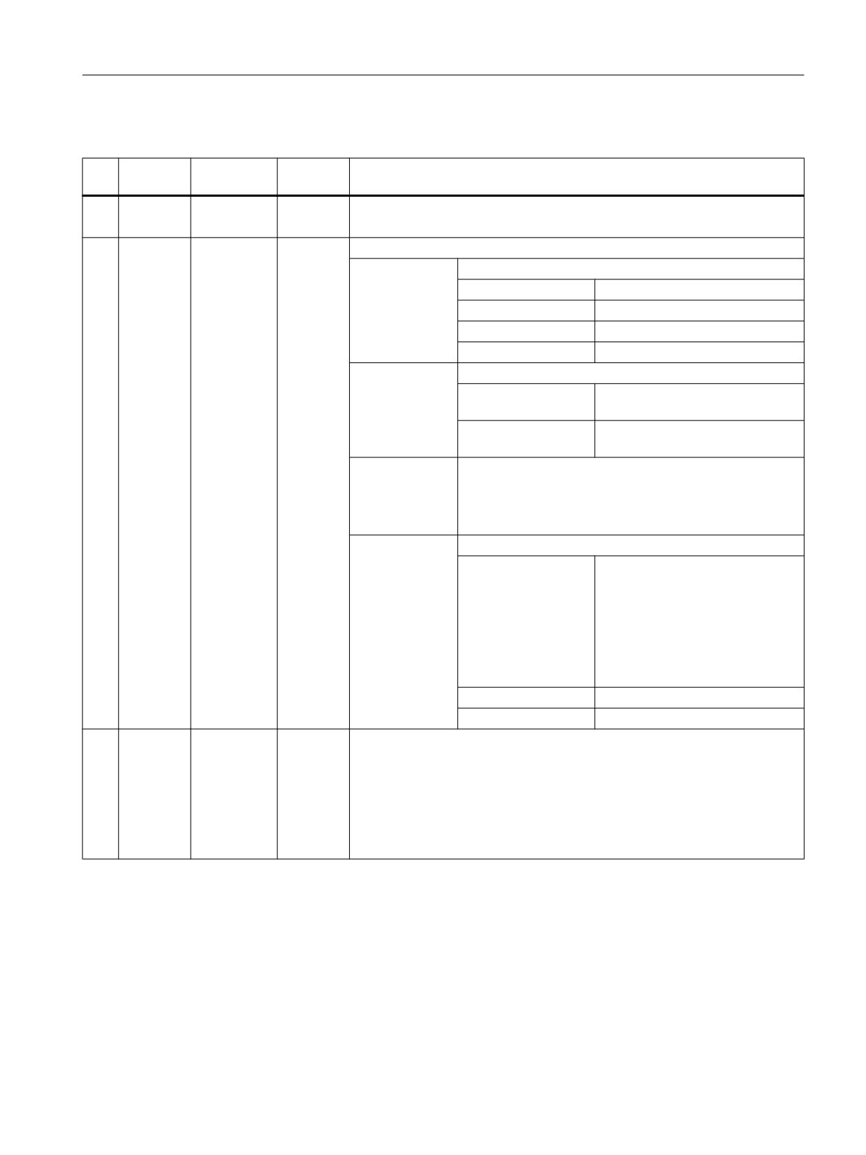
Programming cycles externally
20.1 Technology cycles
Parameters
No.
Parame-
Parameter
Data type
Meaning
ter mask
internal
1
Tolerance
<S_TOL>
REAL
Contour tolerance
The contour tolerance corresponds to the axis tolerance of the geometry axes.
2
<S_TOLM>
INT
Machining type (technology)
UNITS:
0 =
Deselection
1 =
Finishing
2 =
Semi-finishing
3 =
Roughing
TENS:
0 =
Compatibility1) or no orientation tol-
erance
1 =
Orientation tolerance in parameter
<S_OTOL>
HUNDREDS
Assigned
for reasons of
HUNDRED
compatibility
THOUSANDS
ONE MILLION:
0 =
Compatibility. The best available
mold making function is automati-
cally used:
● Option Top Surface not active:
Advanced Surface
● Option Top Surface active:
⇒ Top Surface with smoothing
1 =
Top Surface without smoothing
2 =
Top Surface with smoothing
3
ORI toler-
<S_OTOL>
REAL
Orientation tolerance or version identifier CYCLE832
ance
Tolerance parameter for the orientation of the workpiece.
Is required when executing a high-speed machining program on machines
with dynamic orientation transformation (e.g. 5-axis machining).
Parameter <S_OTOL> must be programmed. This also applies for applications
on 3-axis machines for programs without orientation of the tool (<S_OTOL> =
1).
1)
Orientation tolerance derived from the contour tolerance multiplied by the factor from the cycle setting data SD55441 to
SD55443.
References:
Commissioning Manual, Base Software and Operator Software; SINUMERIK Operate (IM9), Section "Configuring the High-
Speed Settings function (CYCLE832)"
Job Planning
Programming Manual, 12/2018, A5E40869460B AB
779
Programming cycles externally
20.1 Technology cycles
Plain text entry
To improve the readability of the cycle call, parameter <S_TOLM> (machining type) can also
be entered in the plain text. Plain texts are independent of any language. The following entries
are permitted:
_OFF
for
0
Deselection
_FINISH
for
1
Finishing
_SEMIFIN
for
2
Rough-finishing
_ROUGH
for
3
Roughing
_ORI_FINISH
for
11
Finishing with input of an orienta-
tion tolerance
_ORI_SEMIFIN
for
12
Finishing with input of an orienta-
tion tolerance
_ORI_ROUGH
for
13
Roughing with input of an orienta-
tion tolerance
_TOP_SURFACE_SMOOTH_OFF
for
1000000
Top Surface without smoothing
_TOP_SURFACE_SMOOTH_ON
for
2000000
Top Surface with smoothing
For plain text input for Top Surface, plain texts are combined as shown in the following example:
CYCLE832(0.1, _TOP_SURFACE_SMOOTH_OFF+_ORI_FINISH, 1)
Note
The plain texts are based on the function names of the G group 59 (dynamic mode for path
interpolation). With these plain texts, 3-axis machines and machines with multi-axis orientation
transformation (TRAORI) are clearly separated in the application.
Deselecting CYCLE832
When CYCLE832 is deselected, parameter <S_TOL> must be transferred with zero.
Example: CYCLE832(0,0,1)
The syntax CYCLE832() is also permitted for deselecting CYCLE832.
Examples
Example 1: CYCLE832 on 3-axis machine without orientation transformation
a) Cycle call with plain text input
Program code
Comment
G710
; Dimension system is metric.
CYCLE832(0.004,_FINISH,1)
; CYCLE832 call with:
Contour tolerance = 0.004 mm, machining type:
Finishing
; Execution of a high-speed machining program
Job Planning
780
Programming Manual, 12/2018, A5E40869460B AB
Programming cycles externally
20.1 Technology cycles
b) Cycle call without plain text input
Program code
Comment
G710
; See above
CYCLE832(0.004,1,1)
; See above
; See above
Example 2: CYCLE832 on 5-axis machine with orientation transformation
a) Cycle call and deselection with plain text input
Program code
Comment
G710
; Dimension system is metric.
TRAORI
; Activate orientation transformation.
CYCLE832(0.3,_ORI_ROUGH,0.8)
; CYCLE832 call with:
Contour tolerance = 0.3 mm, machining type:
Roughing with input of an orientation toler-
ance; orientation tolerance = 0.8 degrees
; Execution of a high-speed machining program
CYCLE832(0,_OFF,1)
; Contour tolerance = 0,
machining type: Deselection of CYCLE832,
orientation tolerance = 0 degrees
b) Cycle call and deselection without plain text input
Program code
Comment
G710
; See above
TRAORI
; See above
CYCLE832(0.3,13,0.8)
; See above
; See above
CYCLE832(0,0,1)
; See above
20.1.39
CYCLE840 - tapping with compensating chuck
Syntax
CYCLE840(<RTP>, <RFP>, <SDIS>, <DP>, <DPR>, <DTB>, <SDR>, <SDAC>,
<ENC>, <MPIT>, <PIT>, <_AXN>, <_PITA>, <_TECHNO>, <_PITM>, <_PTAB>,
<_PTABA>, <_GMODE>, <_DMODE>, <_AMODE>)
Job Planning
Programming Manual, 12/2018, A5E40869460B AB
781
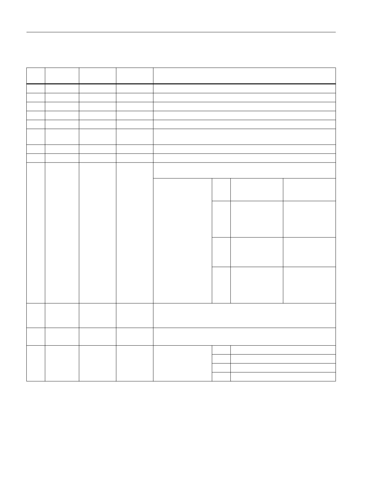
Programming cycles externally
20.1 Technology cycles
Parameters
No.
Parameter
Parameter
Data type
Meaning
mask
internal
1
RP
<RTP>
REAL
Retraction plane (abs)
2
Z0
<RFP>
REAL
Reference point (abs)
3
SC
<SDIS>
REAL
Safety clearance (to be added to reference point, enter without sign)
4
Z1
<DP>
REAL
Drilling depth (abs), see <_AMODE>
5
Z1
<DPR>
REAL
Drilling depth (inc), see <_AMODE>
6
DT
<DTB>
REAL
Dwell time in seconds at drilling depth / safety clearance after retraction,
see <ENC>
7
<SDR>
INT
Direction of rotation for retraction
8
SDE
<SDAC>
INT
Direction of rotation after end of cycle
9
<ENC>
INT
Tapping with spindle mounted encoder (G33)/tapping without spindle
mounted encoder (G63)
0 =
With spindle moun-
- Pitch from
ted encoder
<MPIT>/<PIT>
-
without DT
20 =
With spindle moun-
- Pitch from
ted encoder
<MPIT>/<PIT>
-
with DT after retrac-
tion to safety clear-
ance
11 =
Without spindle
- Pitch from
mounted encoder
<MPIT>/<PIT>
-
with DT at drilling
depth
1 =
Without spindle
- Pitch from pro-
mounted encoder
grammed feedrate
- with DT at drilling
depth (feedrate =
speed · pitch)
10
<MPIT>
REAL
Thread size for "ISO metric" only (pitch is calculated internally during run
time)
Range of values: 3 to 48 (for M3 to M48), alternative to <PIT>
11
<PIT>
REAL
Pitch as a value, for unit see <_PITA>
Range of values: > 0, alternative to MPIT
12
<_AXN>
INT
Drilling axis
0 =
3rd geometry axis
1 =
1st geometry axis
2 =
2nd geometry axis
≥ 3 =
3rd geometry axis
Job Planning
782
Programming Manual, 12/2018, A5E40869460B AB
Programming cycles externally
20.1 Technology cycles
No.
Parameter
Parameter
Data type
Meaning
mask
internal
13
<_PITA>
INT
Pitch unit (evaluation of <PIT> and <MPIT>)
0 =
Pitch in mm
- evalua-
tion<MPIT>/
<PIT>
1 =
Pitch in mm
- evaluation<PIT>
2 =
Pitch in TPI
- evaluation of
<PIT>
(threads per inch)
3 =
Pitch in inches
- evaluation<PIT>
4 =
MODULUS
- evaluation<PIT>
14
<_TECHNO>
INT
Technology1)
UNITS:
Exact stop response
0 =
Exact stop response active as before cy-
cle call
1 =
Exact stop G601
2 =
Exact stop G602
3 =
Exact stop G603
TENS:
Feedforward control
0 =
With/without feedforward control active
as before cycle call
1 =
With feedforward control FFWON
2 =
Without feedforward control FFWOF
15
<_PITM>
STRING[15]
String as marker for pitch input2)
16
<_PTAB>
STRING[5]
String for thread table ("", "ISO", "BSW", "BSP", "UNC")2)
17
<_PTABA>
STRING[20]
String for selection from thread table (e.g. "M 10", "M 12", ...)2)
18
<_GMODE>
INT
Reserved
Job Planning
Programming Manual, 12/2018, A5E40869460B AB
783
Programming cycles externally
20.1 Technology cycles
No.
Parameter
Parameter
Data type
Meaning
mask
internal
19
<_DMODE>
INT
Display mode
UNITS:
Machining plane G17/G18/G19
0 =
Compatibility, the plane effective before
the cycle call remains active
1 =
G17 (only active in the cycle)
2 =
G18 (only active in the cycle)
3 =
G19 (only active in the cycle)
TENS:
Reserved
HUNDREDS:
Reserved
THOUSANDS:
Compatibility mode (for recompilation screen
form only), if MD 52216 bit0 = 11)
0 =
Technology parameters are displayed
(compatibility): TECHNO parameters ef-
fective
1 =
Technology parameters are not dis-
played: Technology active "as before cy-
cle call"
TEN THOUSANDS:
Technology scaling in cycle screen forms
(Page 821)
0 =
Input: Complete
1 =
Input: Simple
20
<_AMODE>
INT
Alternative mode
UNITS:
Drilling depth Z1 (abs/inc)
0 =
Compatibility, from programming <DP>/
<DPR>
1 =
Incremental
2 =
Absolute
1) Technology fields may be hidden, depending on the setting date SD52216 MCS_FUNCTION_MASK_DRILL
2) Parameters 15, 16 and 17 are only used for thread selection in the screen form thread tables. The thread tables cannot
be accessed via cycle definition in cycle run time.
20.1.40
CYCLE899 - open slot
Syntax
CYCLE899(<_RTP>, <_RFP>, <_SDIS>, <_DP>, <_LENG>, <_WID>, <_PA>,
<_PO>, <_STA>, <_MID>, <_MIDA>, <_FAL>, <_FALD>, <_FFP1>, <_CDIR>,
<_VARI>, <_GMODE>, <_DMODE>, <_AMODE>, <_UMODE>, <_FS>, <_ZFS>)
Job Planning
784
Programming Manual, 12/2018, A5E40869460B AB
Programming cycles externally
20.1 Technology cycles
Parameters
No.
Parameter
Parameter
Data type
Meaning
mask
internal
1
RP
<_RTP>
REAL
Retraction plane (abs)
2
Z0
<_RFP>
REAL
Reference point of tool axis (abs)
3
SC
<_SDIS>
REAL
Safety clearance (to be added to reference point, enter without sign)
4
Z1
<_DP>
REAL
Slot depth (abs/inc), see <_AMODE>
5
L
<_LENG>
REAL
Length of slot (inc)
6
W
<_WID>
REAL
Width of slot (inc)
7
X0
<_PA>
REAL
Reference point/starting position 1st axis (abs)
8
Y0
<_PO>
REAL
Reference point/starting position 2nd axis (abs)
9
α0
<_STA>
REAL
Angle of rotation with respect to 1st axis
10
DZ
<_MID>
REAL
Maximum infeed depth (inc), for vortex milling only
11
DXY
<_MIDA>
REAL
Maximum plane infeed, see <_AMODE>
12
UXY
<_FAL>
REAL
Finishing allowance, plane
13
UZ
<_FALD>
REAL
Finishing allowance, depth
14
F
<_FFP1>
REAL
Feedrate
15
<_CDIR>
INT
Milling direction
UNITS:
0 =
Down-cut
1 =
Up-cut
4 =
Alternating
16
<_VARI>
INT
Machining
UNITS:
1 =
Roughing
2 =
Finishing
3 =
Base finishing
4 =
Edge finishing
5 =
Rough-finishing
6 =
Chamfering
TENS:
Reserved
HUNDREDS:
Reserved
THOUSANDS:
1 =
Vortex milling
2 =
Plunge cutting
Job Planning
Programming Manual, 12/2018, A5E40869460B AB
785
Programming cycles externally
20.1 Technology cycles
No.
Parameter
Parameter
Data type
Meaning
mask
internal
17
<_GMODE>
INT
Geometrical mode (evaluation of programmed geometrical data)
UNITS:
Reserved
TENS:
Reserved
HUNDREDS:
Select machining/only calculation of start
point
1 =
Normal machining
THOUSANDS:
Dimensioning via center/edge
0 =
Dimensioning via center
1 =
"Left-hand" dimensioning using
edge ("-" direction of 1st axis)
2 =
"Right-hand" dimensioning using
edge ("+" direction of 1st axis)
18
<_DMODE>
INT
Display mode
UNITS:
Machining plane G17/G18/G19
0 =
Compatibility, the plane effective
before the cycle call remains ac-
tive
1 =
G17 (only active in the cycle)
2 =
G18 (only active in the cycle)
3 =
G19 (only active in the cycle)
TENS:
---
Reserved
HUNDREDS:
---
Reserved
THOUSANDS:
---
Reserved
TEN THOUSANDS:
Technology scaling in cycle screen
forms (Page 821)
0 =
Input: Complete
1 =
Input: Simple
19
<_AMODE>
INT
Alternative mode
UNITS:
Slot depth Z1
0 =
Absolute
1 =
Incremental
TENS:
Unit for plane infeed (<_MIDA>) DXY
0 =
mm
1 =
% of tool diameter
HUNDREDS:
Insertion depth for chamfering ZFS
0 =
Absolute
1 =
Incremental
20
<_UMODE>
INT
Reserved
21
FS
<_FS>
REAL
Chamfer width (inc)
22
ZFS
<_ZFS>
REAL
Insertion depth (tool tip) on chamfering (abs/inc), see <_AMODE>
Job Planning
786
Programming Manual, 12/2018, A5E40869460B AB
Programming cycles externally
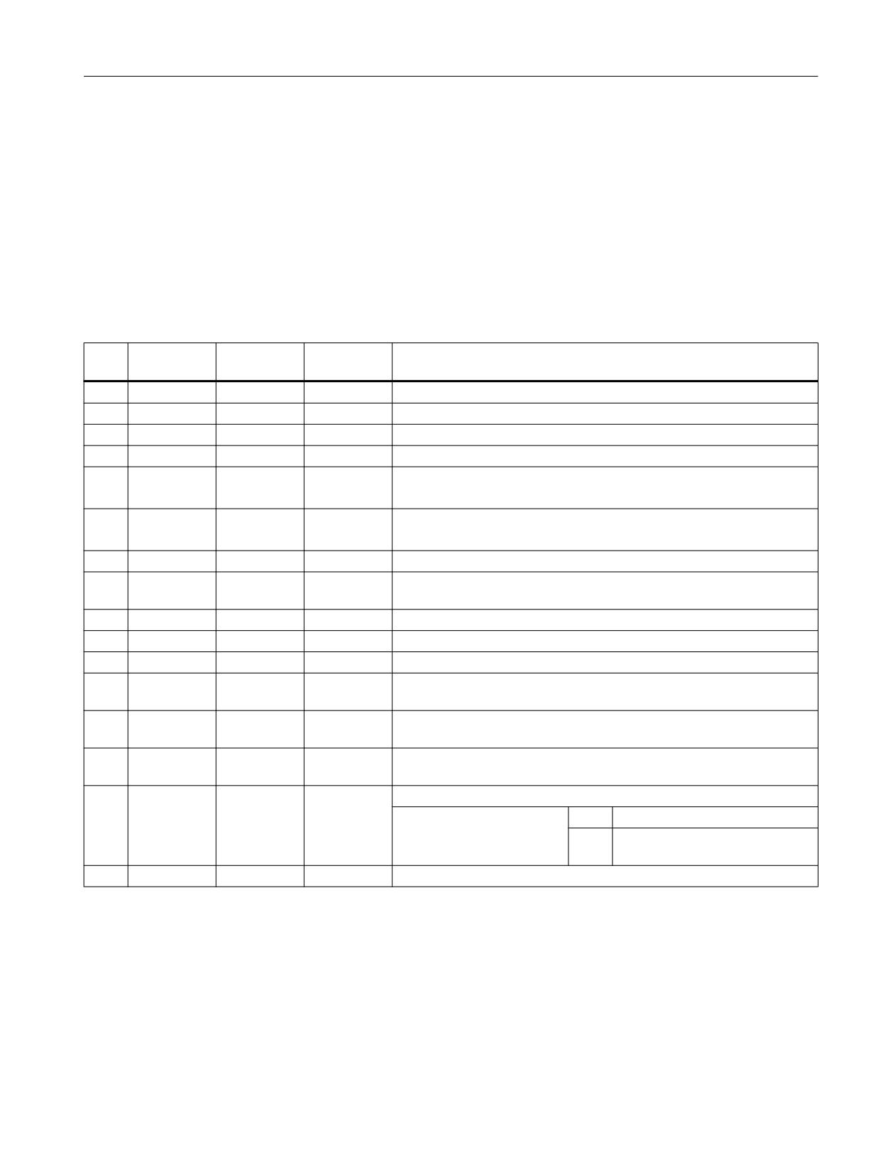
20.1 Technology cycles
20.1.41
CYCLE930 - groove
Syntax
CYCLE930(<_SPD>, <_SPL>, <_WIDG>, <_WIDG2>, <_DIAG>, <_DIAG2>,
<_STA>, <_ANG1>, <_ANG2>, <_RCO1>, <_RCI1>, <_RCI2>, <_RCO2>,
<_FAL>, <_IDEP1>, <_SDIS>, <_VARI>, <_DN>, <_NUM>, <_DBH>, <_FF1>,
<_NR>, <_FALX>, <_FALZ>, <_DMODE>, <_AMODE>)
Parameters
No.
Parameter
Parameter
Data type
Meaning
mask
internal
1
X0
<_SPD>
REAL
Reference point in the plane axis (always diameter)
2
Z0
<_SPL>
REAL
Reference point along the longitudinal axis
3
B1
<_WIDG>
REAL
Width at bottom of groove
4
B2
<_WIDG2>
REAL
Width at top of groove (for interface only)
5
T1
<_DIAG>
REAL
Depth of groove at the reference point
for abs and longitudinal machining = diameter, otherwise inc
6
T2
<_DIAG2>
REAL
Groove depth opposite the reference point (for interface only),
for abs and longitudinal machining = diameter, otherwise inc
7
α0
<_STA>
REAL
Angle of inclination (-180 ≤ <_STA> ≤ 180)
8
α1
<_ANG1>
REAL
Side angle 1 (0 ≤ <_ANG1> < 90) at the side of the groove determined
by the reference point
9
α2
<_ANG2>
REAL
Side angle 2 (0 ≤ <_ANG2> < 90) opposite the reference point
10
R1/FS1
<_RCO1>
REAL
Rounding radius or chamfer width 1, external at the reference point
11
R2/FS2
<_RCI1>
REAL
Rounding radius or chamfer width 2, internal at the reference point
12
R3/FS3
<_RCI2>
REAL
Rounding radius or chamfer width 3, internal opposite the reference
point
13
R4/FS4
<_RCO2>
REAL
Rounding radius or chamfer width 4, external opposite the reference
point
14
U
<_FAL>
REAL
Finishing allowance in X and Z, see <_VARI> (TEN THOUSANDS) (to
be entered without sign)
15
D
<_IDEP1>
REAL
Maximum depth infeed on insertion (enter without sign)
0 =
1. Cut directly to full depth
> 0 =
1. Cut <_IDEP1>, 2nd cut 2 ·
<_IDEP1>, etc.
16
SC
<_SDIS>
REAL
Safety clearance (enter without sign)
Job Planning
Programming Manual, 12/2018, A5E40869460B AB
787
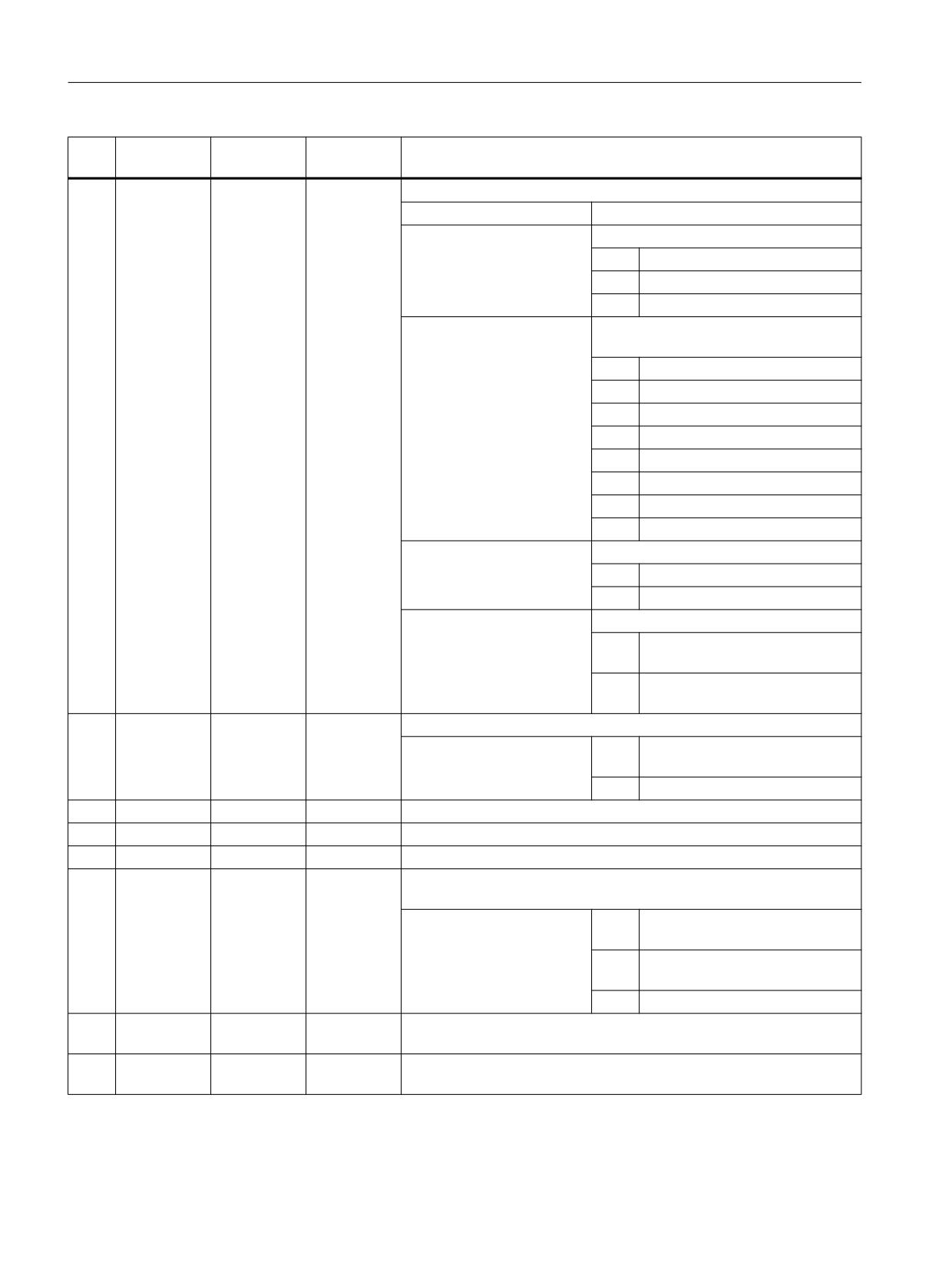
Programming cycles externally
20.1 Technology cycles
No.
Parameter
Parameter
Data type
Meaning
mask
internal
17
<_VARI>
INT
Machining type
UNITS:
Reserved
TENS:
Machining process
1 =
Roughing
2 =
Finishing
3 =
Roughing and finishing
HUNDREDS:
Position longitudinal/transverse external/
internal +Z/+Z and +X/-X
1 =
Longitudinal/external +Z
2 =
Transverse/internal -X
3 =
Longitudinal/internal +Z
4 =
Transverse/internal +X
5 =
Longitudinal/external -Z
6 =
Transverse/external -X
7 =
Longitudinal/internal -Z
8 =
Transverse/external +X
THOUSANDS:
Position of reference point
0 =
Upper reference point
1 =
Lower reference point
TEN THOUSANDS:
Define effect of finishing allowances
0 =
Finishing allowance U parallel to
the contour
1 =
Separate UX and UZ finishing al-
lowances
18
<_DN>
INT
D number for 2nd edge of tool
> 0 =
D number for tool offset of 2nd
edge of grooving tool
0 =
No 2nd edge programmed
19
N
<_NUM>
INT
Number of grooves (0 = 1 groove)
20
DP
<_DBH>
REAL
Distance between grooves (only needed when <_NUM> > 1)
21
F
<_FF1>
REAL
Feedrate
22
<_NR>
INT
Identification for form of groove corresponds to vertical softkey for form
selection
0 =
90° sides without chamfers/
rounding
1 =
Inclined sides with chamfers/
rounding (without α0)
2 =
As 1, but on taper (with α0)
23
UX
<_FALX>
REAL
Finishing allowance in X axis, see <_VARI> (TEN THOUSANDS) (to
be entered without sign)
24
UZ
<_FALZ>
REAL
Finishing allowance in Z axis, see <_VARI> (TEN THOUSANDS) (to
be entered without sign)
Job Planning
788
Programming Manual, 12/2018, A5E40869460B AB
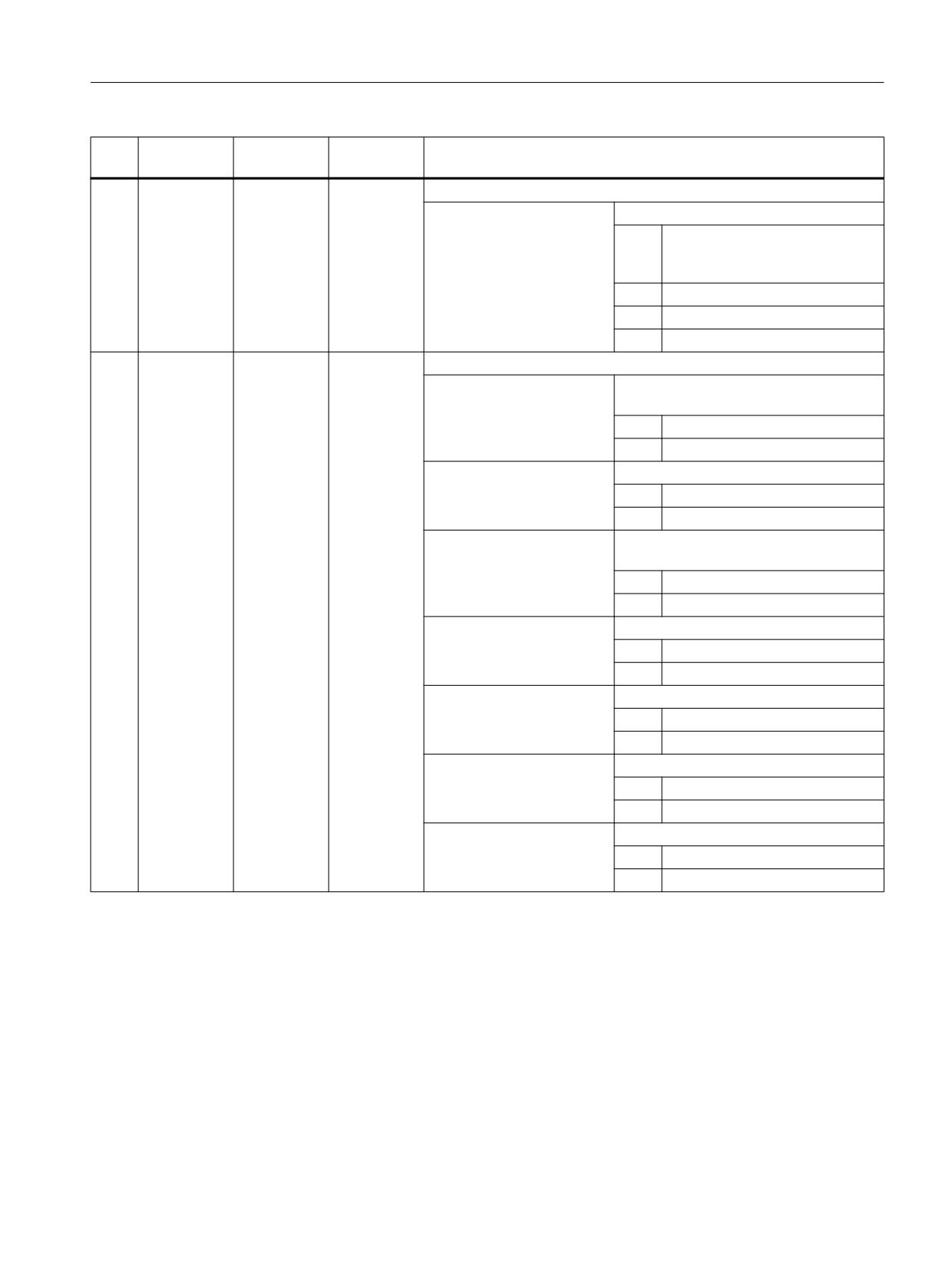
Programming cycles externally
20.1 Technology cycles
No.
Parameter
Parameter
Data type
Meaning
mask
internal
25
<_DMODE>
INT
Display mode
UNITS:
Machining plane G17/G18/G19
0 =
Compatibility, the plane effective
before the cycle call remains ac-
tive
1 =
G17 (only active in the cycle)
2 =
G18 (only active in the cycle)
3 =
G19 (only active in the cycle)
26
<_AMODE>
INT
Alternative mode
UNITS:
Dimensioning for top of groove (for inter-
face only)
0 =
At the reference point
1 =
Opposite the reference point
TENS:
Depth
0 =
Absolute
1 =
Incremental
HUNDREDS:
Dimensioning for width (for interface on-
ly)
0 =
At outer diameter (top)
1 =
At inner diameter (bottom)
THOUSANDS:
Radius/chamfer 1 (<_RCO1>)
0 =
Radius
1 =
Chamfer
TEN THOUSANDS:
Radius/chamfer 2 (<_RCI1>)
0 =
Radius
1 =
Chamfer
HUNDRED THOUSANDS:
Radius/chamfer 3 (<_RCI2>)
0 =
Radius
1 =
Chamfer
ONE MILLION:
Radius/chamfer 4 (<_RCO2>)
0 =
Radius
1 =
Chamfer
20.1.42
CYCLE940 - undercut form E and F / undercut thread
Various undercuts can be programmed using the CYCLE940 cycle. In some cases, these differ
significantly regarding the parameterization.
The additional columns in the table indicate which parameters are required for which undercut
type. They correspond to the vertical selection softkeys in the cycle screen form:
● E: Undercut form E
● F: Undercut form F
Job Planning
Programming Manual, 12/2018, A5E40869460B AB
789
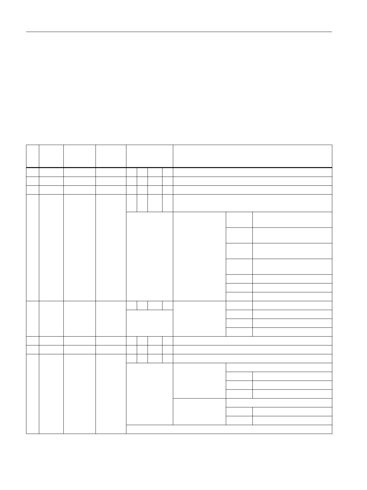
Programming cycles externally
20.1 Technology cycles
● A-D: DIN thread undercut (forms A-D)
● T: Thread undercut (free definition of form)
Syntax
CYCLE940(<_SPD>, <_SPL>, <_FORM>, <_LAGE>, <_SDIS>, <_FFP>, <_VARI>,
<_EPD>, <_EPL>, <_R1>, <_R2>, <_STA>, <_VRT>, <_MID>, <_FAL>,
<_FALX>, <_FALZ>, <_PITI>, <_PTAB>, <_PTABA>, <_DMODE>, <_AMODE>)
Parameters
No
Param-
Parameter
Data type
Prog. for form
Meaning
eter
internal
mask
E
F
A-D
T
1
X0
<_SPD>
REAL
x
x
x
x
Reference point in the plane axis (always diameter)
2
Z0
<_SPL>
REAL
x
x
x
x
Reference point on longitudinal axis (abs)
3
FORM
<_FORM>
CHAR
x
x
x
x
Form of undercut (capital letters, e.g. "T")
Selection, table from which the undercut values should be taken
A =
External, reference DIN76,
A = normal
B =
External, reference DIN76,
B = short
C =
Internal, reference DIN76,
C = normal
D =
Internal, reference DIN76,
D = short
E =
Reference DIN509
F =
Reference DIN509
T=
Free-form
4
POSI-
<_LAGE>
INT
x
x
x
x
Position of under-
0 =
External +Z: \____
|
TION
cut (parallel Z)
1 =
External -Z: |____
/
2 =
Internal +Z: /-----|
3 =
Internal -Z: |-----\
5
SC
<_SDIS>
x
x
x
x
Safety clearance (inc)
6
F
<_FFP>
x
x
x
x
Machining feedrate (mm/rev)
7
<_VARI>
INT
-
-
x
x
Machining type
UNITS:
Machining
1 =
Roughing
2 =
Finishing
3 =
Roughing + finishing
TENS:
Machining strategy
0 =
Parallel to the contour
1 =
Longitudinal
Undercut forms E and F are always machined in a single pass like finishing.
Job Planning
790
Programming Manual, 12/2018, A5E40869460B AB
Programming cycles externally
20.1 Technology cycles
No
Param-
Parameter
Data type
Prog. for form
Meaning
eter
internal
mask
8
X1
<_EPD>
x
x
-
-
Allowance X (abs/inc), see <_AMODE>
-
-
-
x
Undercut depth (abs/inc), see <_AMODE>
9
Z1
<_EPL>
-
x
-
-
Allowance Z
-
-
-
x
Undercut width (abs/inc), see <_AMODE>
10
R1
<_R1>
-
-
-
x
Rounding radius on slopes
11
R2
<_R2>
-
-
-
x
Rounding radius in the corner
12
α
<_STA>
-
-
x
x
Insertion angle
13
VX
<_VRT>
x
x
-
-
Cross-feed X (abs/inc), see <_AMODE>
-
-
x
x
Cross-feed X when finishing, (abs/inc), see <_AMODE>
14
D
<_MID>
-
-
x
x
Depth infeed
15
U
<_FAL>
-
-
x
x
Finishing allowance parallel to contour, see <_AMODE>
16
UX
<_FALX>
-
-
x
x
Finishing allowance X
17
UZ
<_FALZ>
-
-
x
x
Finishing allowance Z
18
P
<_PITI>
INT
-
-
x
-
Select pitch, form A-D, corresponds to M1 ... M68
0 = 0.20
6 = 0.50
12 = 1.25
18 = 3.50
1 = 0.25
7 = 0.60
13 = 1.50
19 = 4.00
2 = 0.30
8 = 0.70
14 = 1.75
20 = 4.50
3 = 0.35
9 = 0.75
15 = 2.00
21 = 5.00
4 = 0.40
10 = 0.80
16 = 2.50
22 = 5.50
5 = 0.45
11 = 1.00
17 = 3.00
23 = 6.00
x
x
-
-
Select radius/depth, form E, F
0 = 0.6 x 0.3
4 = 2.5 x 0.4
8 = 0.1 x 0.1
1 = 1.0 x 0.4
5 = 4.0 x 0.5
9 = 0.2 x 0.1
2 = 1.0 x 0.2
6 = 0.4 x 0.2
3 = 1.6 x 0.3
7 = 0.6 x 0.2
19
<_PTAB>
STRING
String for thread table ("", "ISO", "BSW", "BSP", "UNC")
[5]
(for the surface only)
20
<_PTABA>
STRING
String for selection from thread table
[20]
(e.g. "M 10", "M 12", ...)
(for the surface only)
21
<_DMODE>
INT
Display mode
x
x
x
x
UNITS:
Machining plane G17/G18/G19
0 =
Compatibility, the plane effec-
tive before the cycle call re-
mains active
1 =
G17 (only active in the cycle)
2 =
G18 (only active in the cycle)
3 =
G19 (only active in the cycle)
Job Planning
Programming Manual, 12/2018, A5E40869460B AB
791
Programming cycles externally
20.1 Technology cycles
No
Param-
Parameter
Data type
Prog. for form
Meaning
eter
internal
mask
22
<_AMODE>
INT
Alternative mode
x
x
-
x
UNITS:
Parameter <_EPD> allowance X or under-
cut depth
0 =
Absolute (always diameter)
1 =
Incremental
x
x
-
x
TENS:
Parameter <_EPL> allowance Z or un-
dercut width
0 =
Absolute
1 =
Incremental
x
x
x
x
HUNDREDS:
Parameter <_VRT> cross-feed X
0 =
Absolute (always diameter)
1 =
Incremental
-
-
x
x
THOUSANDS:
Finishing allowance
0 =
Finishing allowance parallel to
the contour (<_FAL>)
1 =
Separate machining allow-
ance (<_FALX>/<_FALZ>)
20.1.43
CYCLE951 - stock removal
Syntax
CYCLE951(<_SPD>, <_SPL>, <_EPD>, <_EPL>, <_ZPD>, <_ZPL>, <_LAGE>,
<_MID>, <_FALX>, <_FALZ>, <_VARI>, <_RF1>, <_RF2>, <_RF3>, <_SDIS>,
<_FF1>, <_NR>, <_DMODE>, <_AMODE>)
Parameters
No.
Parameter
Parameter
Data type
Meaning
mask
internal
1
X0
<_SPD>
REAL
Reference point (abs, always diameter)
2
Z0
<_SPL>
REAL
Reference point (abs)
3
X1
<_EPD>
REAL
End point
4
Z1
<_EPL>
REAL
End point
5
XM
<_ZPD>
REAL
Intermediate point, see <_DMODE> (TENS)
α1
α2
6
ZM
<_ZPL>
REAL
Intermediate point, see <_DMODE> (TENS)
α1
α2
Job Planning
792
Programming Manual, 12/2018, A5E40869460B AB
Programming cycles externally
20.1 Technology cycles
No.
Parameter
Parameter
Data type
Meaning
mask
internal
7
Position
<_LAGE>
INT
Position of stock removal
0 =
External/rear
corner
1 =
External/front
2 =
Internal/rear
3 =
Internal/front
8
D
<_MID>
REAL
Maximum depth infeed on insertion
9
UX
<_FALX>
REAL
Finishing allowance in X
10
UZ
<_FALZ>
REAL
Finishing allowance in Z
11
<_VARI>
INT
Machining type
UNITS:
Stock removal direction (longitudinal or
transverse) in the coordinate system
1 =
Longitudinal
2 =
Face
TENS:
1 =
Roughing to final machining al-
lowance
2 =
Finishing
HUNDREDS:
Reserved
THOUSANDS:
Reserved
TEN THOUSANDS:
Reserved
12
R1/FS1
<_RF1>
REAL
Rounding radius or chamfer width 1, see <_AMODE> (TEN THOU-
SANDS)
13
R2/FS2
<_RF2>
REAL
Rounding radius or chamfer width 2, see <_AMODE> (HUNDRED
THOUSANDS)
14
R3/FS3
<_RF3>
REAL
Rounding radius or chamfer width 3, see <_AMODE> (ONE MILLION)
15
SC
<_SDIS>
REAL
Safety clearance
16
F
<_FF1>
REAL
Feedrate for roughing/finishing
17
<_NR>
INT
Identification of stock removal type (corresponds to vertical softkey for
selecting form):
0 =
Stock removal 1, 90 degree cor-
ner without chamfers/rounding
1 =
Stock removal 2, 90 degree cor-
ner with chamfers/rounding
2 =
Stock removal 3, any corner with
chamfers/rounding
Job Planning
Programming Manual, 12/2018, A5E40869460B AB
793
Programming cycles externally
20.1 Technology cycles
No.
Parameter
Parameter
Data type
Meaning
mask
internal
18
<_DMODE>
INT
Display mode
UNITS:
Machining plane G17/G18/G19
0 =
Compatibility, the plane effective
before the cycle call remains ac-
tive
1 =
G17 (only active in the cycle)
2 =
G18 (only active in the cycle)
3 =
G19 (only active in the cycle)
TENS:
Form of input <_ZPD>/<_ZPL>
0 =
Xm/Zm
1 =
Xm/α1
2 =
Xm/α2
3 =
α1/Zm
4 =
α2/Zm
5 =
α1/α2
21
<_AMODE>
INT
Alternative mode
UNITS:
Intermediate point in X
0 =
Absolute, value of transverse ax-
is in the diameter
1 =
Incremental, value of transverse
axis in the radius
TENS:
Intermediate point in Z
0 =
Absolute
1 =
Incremental
HUNDREDS:
End point in X
0 =
Absolute, value of transverse ax-
is in the diameter
1 =
Incremental, value of transverse
axis in the radius
THOUSANDS:
End point in Z.
0 =
Absolute
1 =
Incremental
TEN THOUSANDS:
Radius/chamfer 1
0 =
Radius
1 =
Chamfer
HUNDRED THOUSANDS:
Radius/chamfer 2
0 =
Radius
1 =
Chamfer
ONE MILLION:
Radius/chamfer 3
0 =
Radius
1 =
Chamfer
Job Planning
794
Programming Manual, 12/2018, A5E40869460B AB

Programming cycles externally
20.1 Technology cycles
20.1.44
CYCLE952 - stock removal / residual stock removal / plunge cutting / residual
plunge cutting / plunge turning / residual plunge turning
Syntax
CYCLE952(<_PRG>, <_CON>, <_CONR>, <_VARI>, <_F>, <_FR>, <_RP>, <_D>,
<_DX>, <_DZ>, <_UX>, <_UZ>, <_U>, <_U1>, <_BL>, <_XD>, <_ZD>, <_XA>,
<_ZA>, <_XB>, <_ZB>, <_XDA>, <_XDB>, <_N>, <_DP>, <_DI>, <_SC>,
<_DN>, <_GMODE>, <_DMODE>, <_AMODE>, <_PK>, <_DCH>, <_FS>)
Parameters
No.
Parameter
Parameter
Data type
Meaning
mask
internal
1
PRG
<_PRG>
STRING[100
Name of the stock removal program
]
2
CON
<_CON>
STRING[100
Name of the program from which the updated contour of the blank is
]
read (for residual machining)
3
CONR
<_CONR>
STRING[100
Name of the program into which the updated contour for the blank (see
]
<_AMODE> TEN THOUSANDS) will be written
Job Planning
Programming Manual, 12/2018, A5E40869460B AB
795
Programming cycles externally
20.1 Technology cycles
No.
Parameter
Parameter
Data type
Meaning
mask
internal
4
<_VARI>
INT
Machining type
UNITS:
Type of stock removal
1 =
Longitudinal
2 =
Face
3 =
Parallel to the contour
TENS:
Machining process (see <_GMODE>
HUNDREDS)
1 =
Roughing
2 =
Finishing
3 =
Reserved
4 =
Roughing, two-channel
5 =
Finishing, two-channel
HUNDREDS:
Machining direction
1 =
Machining direction X -
2 =
Machining direction X +
3 =
Machining direction Z -
4 =
Machining direction Z +
THOUSANDS:
Infeed direction
1 =
External X -
2 =
Internal X +
3 =
Front face Z -
4 =
Rear face Z +
TEN THOUSANDS:
Define effect of finishing allowances
0 =
Separate UX and UZ finishing al-
lowances
1 =
Finishing allowance U parallel to
the contour
HUNDRED THOUSANDS:
Rounding
0 =
Compatibility, automatic rounding
1 =
With rounding at the contour
2 =
Without rounding
3 =
Automatic rounding
ONE MILLION:
Relief cuts
0 =
Position is not evaluated during
grooving, - residual and groove
turning, - remainder
1 =
Machine relief cuts
2 =
No machining of relief cuts
TEN MILLIONS:
Behind/in front of turning center
0 =
Machining in front of the turning
center
1 =
Reserved
Job Planning
796
Programming Manual, 12/2018, A5E40869460B AB
Programming cycles externally
20.1 Technology cycles
No.
Parameter
Parameter
Data type
Meaning
mask
internal
5
F
<_F>
REAL
Feedrate for roughing/finishing
FZ
Infeed abscissa groove turning
6
FR
<_FR>
REAL
Feedrate for insertion into relief cuts, roughing
FX
Infeed ordinate groove turning
7
RP
<_RP>
REAL
Retraction plane for internal machining (abs., always diameter)
8
D
<_D>
REAL
Roughing infeed (see <_AMODE> UNITS)
9
DX
<_DX>
REAL
X infeed (see <_AMODE> UNITS)
10
DZ
<_DZ>
REAL
Z infeed (see <_AMODE> UNITS)
11
UX
<_UX>
REAL
Finishing allowance X, (see <_VARI> TEN THOUSANDS)
12
UZ
<_UZ>
REAL
Finishing allowance Z, (see <_VARI> TEN THOUSANDS)
13
U
<_U>
REAL
Finishing allowance parallel to contour, (see <_VARI> TEN THOU-
SANDS)
14
U1
<_U1>
REAL
Additional finishing allowance while finishing (see <_AMODE> THOU-
SANDS)
15
BL
<_BL>
INT
Definition of blank
1 =
Cylinder with allowance
2 =
Allowance at contour of finished
part
3 =
Contour of blank is specified
16
XD
<_XD>
REAL
Definition of blank X (see <_AMODE> HUNDRED THOUSANDS)
17
ZD
<_ZD>
REAL
Definition of blank Z (see <_AMODE> ONE MILLION)
18
XA
<_XA>
REAL
Limit 1 X (abs., always diameter)
19
ZA
<_ZA>
REAL
Limit 1 Z (abs.)
20
XB
<_XB>
REAL
Limit 2 X (see <_AMODE> TEN MILLIONS)
21
ZB
<_ZB>
REAL
Limit 2 Z (see <_AMODE> HUNDRED MILLIONS)
22
XDA
<_XDA>
REAL
Grooving limit 1 for the 1st groove position on the end face (abs., always
diameter)
23
XDB
<_XDB>
REAL
Grooving limit 2 for the 1st groove position on the end face (abs., always
diameter)
24
N
<_N>
INT
Number of grooves
25
DP
<_DP>
REAL
Distance between grooves
Longitudinal groove: Parallel to Z axis
Transverse groove: Parallel to X axis
26
DI
<_DI>
REAL
Distance for interruption of
0 =
No interruption
infeed
> 0 =
With interruption
27
SC
<_SC>
REAL
Safety clearance for avoiding obstacles, incremental
28
D2
<_DN>
INT
D number for 2nd cutting edge if not programmed ⇒ D+1
Job Planning
Programming Manual, 12/2018, A5E40869460B AB
797
Programming cycles externally
20.1 Technology cycles
No.
Parameter
Parameter
Data type
Meaning
mask
internal
29
<_GMODE>
INT
Geometrical mode (evaluation of programmed geometrical data)
UNITS:
Re-
serve
d
TENS:
Re-
serve
d
HUNDREDS:
Select machining/only calculation of start
point
0 =
Normal machining (no compatibil-
ity mode needed)
1 =
Normal machining
2 =
Calculate start point - no machin-
ing (only for call from ShopMill/
ShopTurn)
THOUSANDS:
Limit
0 =
No
1 =
Yes
TEN THOUSANDS:
Enter limit 1 X
0 =
No
1 =
Yes
HUNDRED THOUSANDS:
Enter limit 2 X
0 =
No
1 =
Yes
ONE MILLION:
Enter limit 1 Z
0 =
No
1 =
Yes
TEN MILLIONS:
Enter limit 2 Z
0 =
No
1 =
Yes
Job Planning
798
Programming Manual, 12/2018, A5E40869460B AB
Programming cycles externally
20.1 Technology cycles
No.
Parameter
Parameter
Data type
Meaning
mask
internal
30
<_DMODE>
INT
Display mode
UNITS:
Machining plane G17/G18/G19
0 =
Compatibility, the plane effective
before the cycle call remains ac-
tive
1 =
G17 (only active in the cycle)
2 =
G18 (only active in the cycle)
3 =
G19 (only active in the cycle)
TENS:
Technology mode
1 =
Stock removal along the contour
2 =
Contour grooving
3 =
Groove turning
HUNDREDS:
Machine residual material
0 =
No
1 =
Yes
THOUSANDS:
---
Reserved
TEN THOUSANDS:
Technology scaling in cycle screen
forms (Page 821)
0 =
Input: Complete
1 =
Input: Simple
HUNDRED THOUSANDS:
Automatic program name
0 =
No
1 =
Yes
Job Planning
Programming Manual, 12/2018, A5E40869460B AB
799
Programming cycles externally
20.1 Technology cycles
No.
Parameter
Parameter
Data type
Meaning
mask
internal
31
<_AMODE>
INT
Alternative mode
UNITS:
Select infeed
0 =
DX and DZ infeed for stock re-
moval parallel to contour
1 =
D infeed
TENS:
Infeed strategy
0 =
Variable cutting depth (90 ...
100%)
1 =
Constant cutting depth
HUNDREDS:
Cut segmentation
0 =
Uniform
1 =
Align to edges
THOUSANDS:
Select contour allowance U1, double fin-
ishing
0 =
No
1 =
Yes
TEN THOUSANDS:
Update selection of blank
0 =
No
1 =
Yes
HUNDRED THOUSANDS:
Select allowance on blank XD
0 =
Absolute, value of transverse ax-
is in the diameter
1 =
Incremental, value of transverse
axis in the radius
ONE MILLION:
Select allowance on blank ZD
0 =
Absolute
1 =
Incremental
TEN MILLIONS:
Select limit 2 XB
0 =
Absolute, value of transverse ax-
is in the diameter
1 =
Incremental, value of transverse
axis in the radius
HUNDRED MILLION:
Select limit 2 ZB
0 =
Absolute
1 =
Incremental
ONE BILLION:
0 =
Leading channel
1 =
Following channel
32
<_PK>
INT
Number of the partner channel if there are more than two channels
available at the machine.
33
DCH
<_DCH>
REAL
Channel offset
34
FS
<_FS>
REAL
Finishing feedrate during complete machining
Job Planning
800
Programming Manual, 12/2018, A5E40869460B AB

Programming cycles externally
20.1 Technology cycles
20.1.45
CYCLE4071 - longitudinal grinding with infeed at the reversal point
Syntax
CYCLE4071(<S_A>, <S_B>, <S_W>, <S_U>, <S_I>, <S_K>, <S_H>, <S_A1>,
<S_A2>)
Parameters
No.
Parameter
Data type
Meaning
1
<S_A>
REAL
Infeed depth at the start
2
<S_B>
REAL
Infeed depth at the end
3
<S_W>
REAL
Grinding width
4
<S_U>
REAL
Sparking-out time
5
<S_I>
REAL
Feedrate for infeed
6
<S_K>
REAL
Feedrate for transverse infeed
7
<S_H>
INT
Number of repetitions
8
<S_A1>
AXIS
Infeed axis (optional) or 1st geometry axis
9
<S_A2>
AXIS
Oscillating axis (optional) or 2nd geometry axis
Function
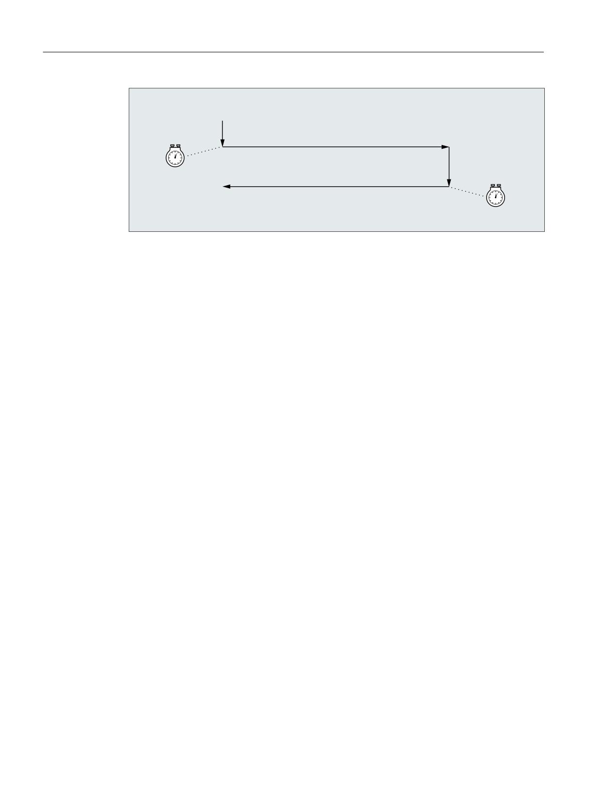
The cycle is used for the execution of <S_H> infeeds. The infeed depth at the start and at the
end can be different. There is a tangential motion between the infeeds.
Sequence
1. Start of the cycle at the current position of the oscillating axis.
2. Traversing of the infeed axis to the infeed depth at the start P1 <S_A> with the feedrate for
infeed P5 <S_I>.
3. Sparking out with the sparking-out time P4 <S_U>.
4. Traversing of the oscillating axis with the grinding width P3 <S_W> as travel path and the
feedrate for transverse infeed P6 <S_K>.
5. Traversing of the infeed axis to the infeed depth at the end P2 <S_B> with the feedrate for
infeed P5 <S_I>.
6. Sparking out with the sparking-out time P4 <S_U>.
7. Traversing of the oscillating axis with the grinding width P4 <S_A> as travel path to the
starting point and the feedrate for transverse infeed P6 <S_K>.
The sequence cannot be interrupted with a single block.
The sequence is repeated according to the number of programmed repetitions P7 (<S_H>).
Job Planning
Programming Manual, 12/2018, A5E40869460B AB
801
Programming cycles externally
20.1 Technology cycles
6B$!
) 6B,!
6B:!
) 6B.!
6B8!
6B%!
) 6B,!
6B:!
) 6B.!
6B8!
Example
Executing two oscillating motions with the following cycle parameters:
● Infeed depth at the start: 0.02 mm
● Infeed depth at the end: 0.01 mm
● Stroke: 100 mm
● Sparking-out time: 1 s
● Infeed feedrate: 1 mm/min
● Transverse feedrate: 1000 mm/min
● Repetitions: 2
● Oscillating and infeed axes: Standard geometry axes
Program code
N10 T1 D1
N20 CYCLE4071(0.02,0.01,100,1,1,1000,2)
N30 M30
20.1.46
CYCLE4072 - longitudinal grinding with infeed at the reversal point and cancel
signal
Syntax
CYCLE4072(<S_GAUGE>, <S_A>, <S_B>, <S_W>, <S_U>, <S_I>, <S_K>,
<S_H>, <S_A1>, <S_A2>)
Job Planning
802
Programming Manual, 12/2018, A5E40869460B AB

Programming cycles externally
20.1 Technology cycles
Parameters
No.
Parameter
Data type
Meaning
1
<S_GAUGE>
STRING
Cancel conditions for infeed:
1. Number of a rapid input
2. Logical expression
2
<S_A>
REAL
Infeed depth at the start
3
<S_B>
REAL
Infeed depth at the end
4
<S_W>
REAL
Grinding width
5
<S_U>
REAL
Sparking-out time
6
<S_I>
REAL
Feedrate for infeed
7
<S_K>
REAL
Feedrate for transverse infeed
8
<S_H>
INT
Number of repetitions
9
<S_A1>
AXIS
Infeed axis (optional) or 1st geometry axis
10
<S_A2>
AXIS
Oscillating axis (optional) or 2nd geometry axis
Function
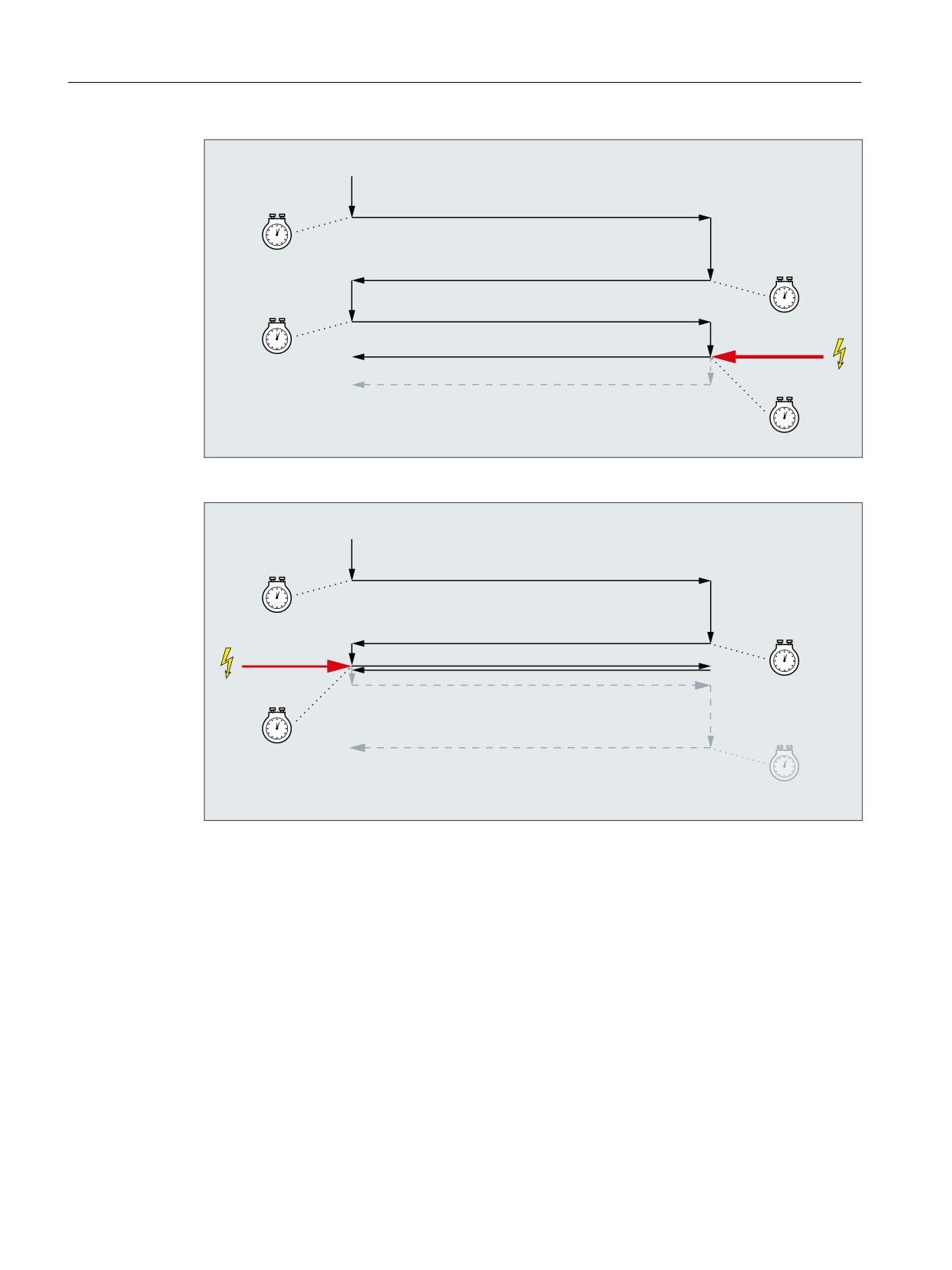
The cycle is used for the execution of <S_H> infeeds taking into account an external cancel
signal. The infeed depth can be different at the start and at the end. There is a tangential motion
between the infeeds. The depth infeed is cancelled when the cancel condition is satisfied. A
complete stroke is always performed after the cancellation of the depth infeed.
Sequence
1. Start of the cycle at the current position of the oscillating axis.
2. Traversing of the infeed axis to the infeed depth at the start P2 <S_A> with the feedrate for
infeed P6 <S_I>.
3. Sparking out with the sparking-out time P5 <S_U>.
4. Traversing of the oscillating axis with the grinding width P4 <S_W> as travel path and the
feedrate for transverse infeed P7 <S_K>.
5. Traversing of the infeed axis to the infeed depth at the end P3 <S_B> with the feedrate for
infeed P6 <S_I>.
6. Sparking out with the sparking-out time P5 <S_U>.
7. Traversing of the oscillating axis with the grinding width P4 <S_W> as travel path to the
starting point and the feedrate for transverse infeed P7 <S_K>.
8. Without cancellation: The sequence described above is repeated until the number of
programmed repetitions P7 (<S_H>) is reached.
With cancellation: The machining is stopped when the next start point is reached.
The sequence cannot be interrupted by a single block.
Job Planning
Programming Manual, 12/2018, A5E40869460B AB
803
Programming cycles externally
20.1 Technology cycles
6B$!
) 6B,!
6B:!
) 6B.!
6B8!
6B%!
) 6B,!
6B:!
) 6B.!
6B$!
) 6B,!
6B8!
6B:!
) 6B.!
6B%!
) 6B,!
6B8!
6B:!
) 6B.!
6B*$8*(!
6B8!
Figure 20-1
Cancellation of the infeed at the end
6B$!
) 6B,!
6B:!
) 6B.!
6B8!
6B%!
) 6B,!
6B:!
) 6B.!
6B$!
) 6B,!
6B:!
) 6B.!
6B8!
6B*$8*(!
6B8!
Figure 20-2
Cancellation of the infeed at the start
Resources
As resources, the cycle uses a block-wide synchronized action and a synchronized action
variable. The synchronized action is determined dynamically from the free area of the
synchronized action range (CUS.DIR - 1 ..., CMA.DIR - 1000 ..., CST.DIR - 1199 ...).
SYG_IS[1] is used as the synchronized action variable.
Job Planning
804
Programming Manual, 12/2018, A5E40869460B AB
Programming cycles externally
20.1 Technology cycles
Examples
Example 1: Oscillation with two strokes:
Cycle parameters
● Infeed depth at the start: 0.02 mm
● Infeed depth at the end: 0.01 mm
● Stroke: 100 mm
● Sparking-out time: 1 s
● Infeed feedrate: 1 mm/min
● Transverse feedrate: 1000 mm/min
● Repetitions: 2
● Oscillating and infeed axes: Standard geometry axes
Cancel signal Rapid input 1 ($A_IN[1] )
Program code
N10 T1 D1
N20 CYCLE4072("1",0.02,0.01,100,1,1,1000,2)
N30 M30
Example 2: Oscillation with two strokes:
Cycle parameters
● Infeed depth at the start: 0.02 mm
● Infeed depth at the end: 0.01 mm
● Stroke: 100 mm
● Sparking-out time: 1 s
● Infeed feedrate: 1 mm/min
● Transverse feedrate: 1000 mm/min
● Repetitions: 2
● Oscillating and infeed axes: Standard geometry axes
Cancel signal Variable $A_DBR[20] < 0.01
Program code
N10 T1 D1
N20 CYCLE4072("($A_DBR[20]<0.01)",0.02,0.01,100,1,1,1000,2)
N30 M30
Job Planning
Programming Manual, 12/2018, A5E40869460B AB
805

Programming cycles externally
20.1 Technology cycles
20.1.47
CYCLE4073 - longitudinal grinding with continuous infeed
Syntax
CYCLE4073(<S_A>, <S_B>, <S_W>, <S_U>, <S_K>, <S_H>, <S_A1>, <S_A2>)
Parameters
No.
Parameter
Data type
Meaning
1
<S_A>
REAL
Infeed depth at the start
2
<S_B>
REAL
Infeed depth at the end
3
<S_W>
REAL
Grinding width
4
<S_U>
REAL
Sparking-out time
5
<S_K>
REAL
Feedrate for transverse infeed
6
<S_H>
INT
Number of repetitions
7
<S_A1>
AXIS
Infeed axis (optional) or 1st geometry axis
8
<S_A2>
AXIS
Oscillating axis (optional) or 2nd geometry axis
Function
The cycle is used for the execution of <S_H> infeeds. The infeed from the start to the end and
from the end to the start can be different.
Sequence
1. Start of the cycle at the current position of the oscillating axis with infeed depth 0
2. Traversing of the oscillating axis with the grinding width P3 <S_W> as travel path and
feedrate for transverse infeed P5 <S_K> with continuous increase in the infeed depth up
to the infeed depth at the start P1 <S_A>.
3. Sparking out with the sparking-out time P4 <S_U>.
4. Traversing of the oscillating axis with the grinding width P3 <S_W> as travel path to the
starting point and feedrate for transverse infeed P5 <S_K> with continuous increase in the
infeed depth up to the infeed depth at the end P2 <S_B>.
5. Sparking out with the sparking-out time P4 <S_U>.
The sequence cannot be interrupted by a single block.
The sequence is repeated according to the number of programmed repetitions P7 (<S_H>).
Job Planning
806
Programming Manual, 12/2018, A5E40869460B AB
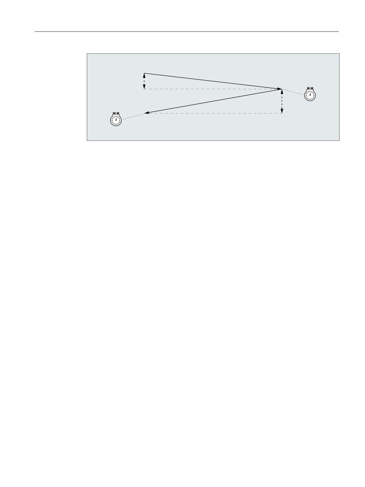
Programming cycles externally
20.1 Technology cycles
6B$!
6B:! ) 6B.!
6B8!
6B%!
6B:! ) 6B.!
6B8!
Example
Oscillation with two strokes:
Cycle parameters
● Infeed depth at the start: 0.02 mm
● Infeed depth at the end: 0.01 mm
● Stroke: 100 mm
● Sparking-out time: 1 s
● Transverse feedrate: 1000 mm/min
● Repetitions: 2
● Oscillating and infeed axes: Standard geometry axes
Program code
N10 T1 D1
N20 CYCLE4073(0.02,0.01,100,1,1000,2)
N30 M30
20.1.48
CYCLE4074 - longitudinal grinding with continuous infeed and cancel signal
Syntax
CYCLE4074(<S_GAUGE>, <S_A>, <S_B>, <S_W>, <S_U>, <S_K>, <S_H>,
<S_A1>, <S_A2>)
Job Planning
Programming Manual, 12/2018, A5E40869460B AB
807

Programming cycles externally
20.1 Technology cycles
Parameters
No.
Parameter
Data type
Meaning
1
<S_GAUGE>
STRING
Cancel conditions for infeed:
1. Number of a rapid input
2. Logical expression
2
<S_A>
REAL
Infeed depth at the start
3
<S_B>
REAL
Infeed depth at the end
4
<S_W>
REAL
Grinding width
5
<S_U>
REAL
Sparking-out time
6
<S_K>
REAL
Feedrate for transverse infeed
7
<S_H>
INT
Number of repetitions
8
<S_A1>
AXIS
Infeed axis (optional) or 1st geometry axis
9
<S_A2>
AXIS
Oscillating axis (optional) or 2nd geometry axis
Function
The cycle is used for the execution of <S_H> infeeds taking into account an external cancel
signal, for example. The infeed depth can be different at the start and at the end. The depth
infeed is cancelled when the cancel condition is satisfied. A complete stroke is always
performed after the cancellation of the depth infeed.
Sequence
1. Start of the cycle at the current position of the oscillating axis with infeed depth 0
2. Traversing of the oscillating axis with the grinding width P4 <S_W> as travel path and
feedrate for transverse infeed P6 <S_K> with continuous increase in the infeed depth up
to the infeed depth at the start P2 <S_A>.
3. Sparking out with the sparking-out time P5 <S_U>.
4. Traversing of the oscillating axis with the grinding width P4 <S_W> as travel path to the
starting point and feedrate for transverse infeed P6 <S_K> with continuous increase in the
infeed depth up to the infeed depth at the end P3 <S_B>.
5. Sparking out with the sparking-out time P5 <S_U>.
6. Without cancellation: The sequence described above is repeated until the number of
programmed repetitions P7 (<S_H>) is reached.
With cancellation: The depth infeed is cancelled. The machining is stopped when the next
start point is reached.
The sequence cannot be interrupted by a single block.
Job Planning
808
Programming Manual, 12/2018, A5E40869460B AB
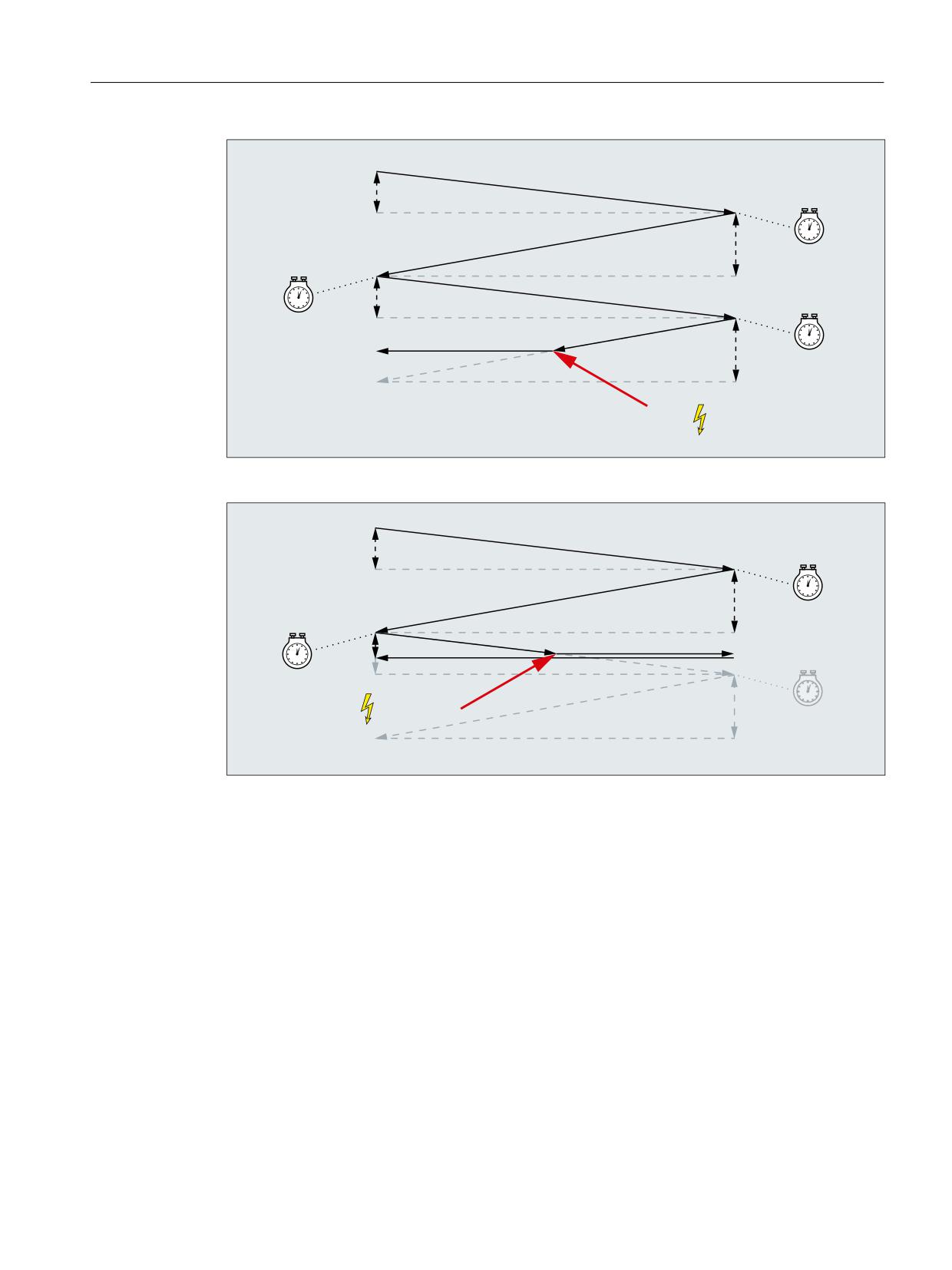
Programming cycles externally
20.1 Technology cycles
6B$!
6B:! ) 6B.!
6B8!
6B%!
6B:! ) 6B.!
6B8!
6B$!
6B:! ) 6B.!
6B8!
6B%!
6B*$8*(!
Figure 20-3
Cancellation of the infeed from the end to the start
6B$!
6B:! ) 6B.!
6B8!
6B%!
6B:! ) 6B.!
6B8!
6B$!
6B*$8*(!
Figure 20-4
Cancellation of the infeed from the start to the end
Resources
As resources, the cycle uses a block-wide synchronized action and a synchronized action
variable. The synchronized action is determined dynamically from the free area of the
synchronized action range (CUS.DIR - 1 ..., CMA.DIR - 1000 ..., CST.DIR - 1199 ...).
SYG_IS[1] is used as the synchronized action variable.
Examples
Example 1: Oscillation with two strokes:
Cycle parameters
● Infeed depth at the start: 0.02 mm
● Infeed depth at the end: 0.01 mm
Job Planning
Programming Manual, 12/2018, A5E40869460B AB
809
Programming cycles externally
20.1 Technology cycles
● Stroke: 100 mm
● Sparking-out time: 1 s
● Transverse feedrate: 1000 mm/min
● Repetitions: 2
● Oscillating and infeed axes: Standard geometry axes
Cancel signal Rapid input 1 ($A_IN[1] )
Program code
N10 T1 D1
N20 CYCLE4074("1",0.02,0.01,100,1,1000,2)
N30 M30
Example 2: Oscillation with two strokes:
Cycle parameters
● Infeed depth at the start: 0.02 mm
● Infeed depth at the end: 0.01 mm
● Stroke: 100 mm
● Sparking-out time: 1 s
● Transverse feedrate: 1000 mm/min
● Repetitions: 2
● Oscillating and infeed axes: Standard geometry axes
Cancel signal Variable $A_DBR[20] < 0.01
Program code
N10 T1 D1
N20 CYCLE4074("($A_DBR[20]<0.01)",0.02,0.01,100,1,1000,2)
N30 M30
20.1.49
CYCLE4075 - surface grinding with infeed at the reversal point
Syntax
CYCLE4075(<S_I>, <S_J>, <S_K>, <S_A>, <S_R>, <S_F>, <S_P>, <S_A1>,
<S_A2>)
Parameters
No.
Parameter
Data type
Meaning
1
<S_I>
REAL
Infeed depth at the start
2
<S_J>
REAL
Infeed depth at the end
Job Planning
810
Programming Manual, 12/2018, A5E40869460B AB
Programming cycles externally
20.1 Technology cycles
No.
Parameter
Data type
Meaning
3
<S_K>
REAL
Total infeed depth
4
<S_A>
REAL
Grinding width
5
<S_R>
REAL
Feedrate for infeed
6
<S_F>
REAL
Feedrate for transverse infeed
7
<S_P>
REAL
Sparking-out time
8
<S_A1>
AXIS
Infeed axis (optional)
9
<S_A2>
AXIS
Oscillating axis (optional)
Function
The cycle is used for machining with a total infeed depth P3 <S_K> in infeed steps. The infeed
depths at the start P1 <S_I> and at the end P2 <S_J> can be different. There is a tangential
motion between the infeeds.
The positional data P1 to P4 can be negative or positive.
The specification of the infeed axis P8 <S_A1> and/or oscillating axis P9 <S_A2> are optional.
If one or both parameters are not specified, the cycle uses the first two geometry axes of the
channel.
If the sum of the infeed depth at the start P1 <S_I> and at the end P2 <S_J> is 0 or the total
infeed depth P3 <S_K> is 0, only a sparking-out stroke is performed.
Sequence
1. Start of the cycle at the current position of the oscillating axis.
2. Traversing of the infeed axis to the infeed depth at the start P1 <S_I> with the feedrate for
infeed P5 <S_R>.
3. Sparking out with the sparking-out time P7 <S_P>.
4. Traversing of the oscillating axis with the grinding width P4 <S_A> as travel path and the
feedrate for transverse infeed P6 <S_F>.
5. Traversing of the infeed axis to the infeed depth at the end P2 <S_J> with the feedrate for
infeed P5 <S_R>.
6. Sparking out with the sparking-out time P7 <S_P>.
7. Traversing of the oscillating axis with the grinding width P4 <S_A> as travel path to the
starting point and the feedrate for transverse infeed P6 <S_F>.
The sequence cannot be interrupted with a single block.
The sequence is repeated until the total infeed depth P3 <S_K> has been reached. The last
stroke is then distributed unevenly.
Job Planning
Programming Manual, 12/2018, A5E40869460B AB
811
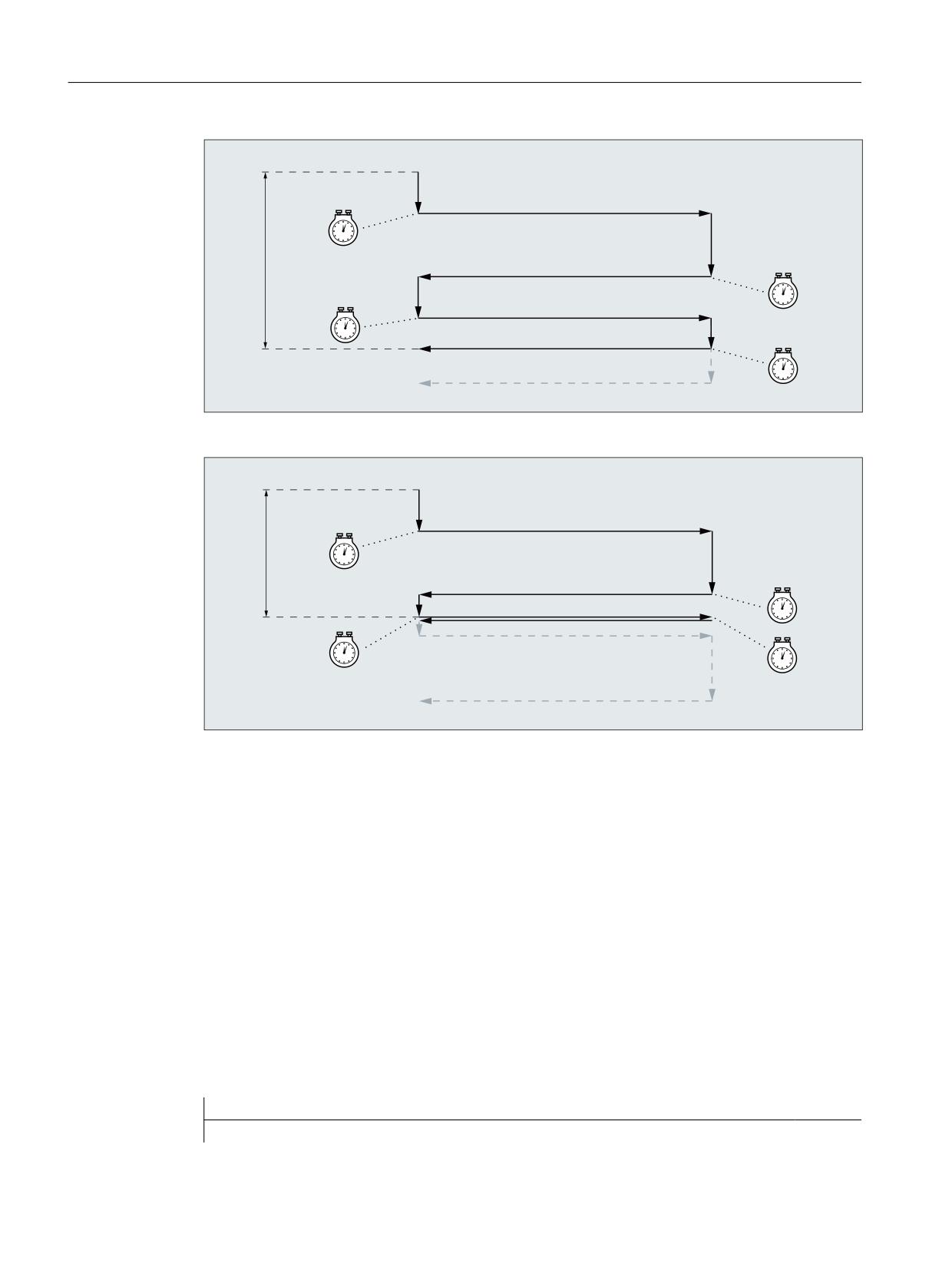
Programming cycles externally
20.1 Technology cycles
6B,!
) 6B5!
6B$!
) 6B)!
6B3!
6B-!
) 6B5!
6B.!
6B$!
) 6B)!
6B,!
) 6B5!
6B3!
6B$!
) 6B)!
6B3!
6B-!
) 6B5!
6B$!
) 6B)!
6B3!
Figure 20-5
Total infeed depth reached with infeed at the second reversal point
6B,!
) 6B5!
6B$!
) 6B)!
6B.!
6B3!
6B-!
) 6B5!
6B$!
) 6B)!
6B,!
) 6B5!
6B$!
) 6B)!
6B3!
6B3!
6B3!
Figure 20-6
Total infeed depth reached with infeed at the first reversal point
Example
Oscillation with:
●
0.02 mm infeed depth at the start
●
0.01mm infeed depth at the end
● Total infeed depth 1 mm
●
100 mm stroke
● Infeed feedrate 1 mm/min
● Transverse feedrate 1000 mm/min
●
1 second sparking-out time
● Standard geometry axes
Program code
N10 T1 D1
Job Planning
812
Programming Manual, 12/2018, A5E40869460B AB

Programming cycles externally
20.1 Technology cycles
Program code
N20 CYCLE4075(0.02,0.01,1,100,1,1000,1)
N30 M30
20.1.50
CYCLE4077 - surface grinding with infeed at the reversal point and cancel signal
Syntax
CYCLE4077(<S_GAUGE>, <S_I>, <S_J>, <S_K>, <S_A>, <S_R>, <S_F>,
<S_P>, <S_A1>, <S_A2>)
Parameters
No.
Parameter
Data type
Meaning
1
<S_GAUGE>
STRING
Cancel condition for infeed:
● Number of a rapid input
● Logical expression
2
<S_I>
REAL
Infeed depth at the start
3
<S_J>
REAL
Infeed depth at the end
4
<S_K>
REAL
Total infeed depth
5
<S_A>
REAL
Grinding width
6
<S_R>
REAL
Feedrate for infeed
7
<S_F>
REAL
Feedrate for transverse infeed
8
<S_P>
REAL
Sparking-out time
9
<S_A1>
AXIS
Infeed axis (optional)
10
<S_A2>
AXIS
Oscillating axis (optional)
Function
The cycle is used for machining with a total infeed depth P4 <S_K> in infeed steps. The infeed
depths at the start P2 <S_I> and at the end P3 <S_J> can be different. There is a tangential
motion between the infeeds. The depth infeed is cancelled when the cancel signal of the rapid
input is 1 or the cancel condition is satisfied. A complete stroke is performed after the
cancellation.
The positional data P2 to P5 can be negative or positive.
The specification of the infeed axis P9 <S_A1> and/or oscillating axis P10 <S_A2> are optional.
If one or both parameters are not specified, the cycle uses the first two geometry axes of the
channel.
If the sum of the infeed depth at the start P2 <S_I> and at the end P3 <S_J> is 0 or the total
infeed depth P4 <S_K> is 0, only a sparking-out stroke is performed.
Job Planning
Programming Manual, 12/2018, A5E40869460B AB
813
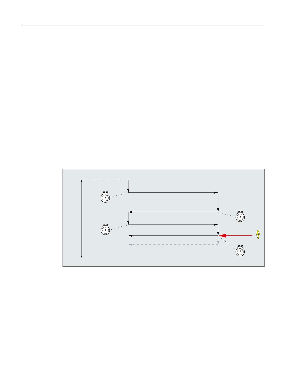
Programming cycles externally
20.1 Technology cycles
Sequence
1. Start of the cycle at the current position of the oscillating axis.
2. Traversing of the infeed axis to the infeed depth at the start P2 <S_I> with the feedrate for
infeed P6 <S_R>.
3. Sparking out with the sparking-out time P8 <S_P>.
4. Traversing of the oscillating axis with the grinding width P5 <S_A> as travel path and the
feedrate for transverse infeed P7 <S_F>.
5. Traversing of the infeed axis to the infeed depth at the end P3 <S_J> with the feedrate for
infeed P6 <S_R>.
6. Sparking out with the sparking-out time P8 <S_P>.
7. Traversing of the oscillating axis with the grinding width P5 <S_A> as travel path to the
starting point and the feedrate for transverse infeed P7 <S_F>.
8. Without cancellation: The sequence described above is repeated until the total infeed depth
P4 <S_K> has been reached. The last stroke is then distributed unevenly.
With cancellation: The machining is stopped at the start point.
The sequence cannot be interrupted with a single block.
6B,!
) 6B5!
6B$!
) 6B)!
6B3!
6B-!
) 6B5!
6B$!
) 6B)!
6B,!
) 6B5!
6B3!
6B.!
6B$!
) 6B)!
6B-!
) 6B5!
6B3!
6B$!
) 6B)!
6B*$8*(!
6B3!
Figure 20-7
Cancellation of the infeed at the end
Job Planning
814
Programming Manual, 12/2018, A5E40869460B AB
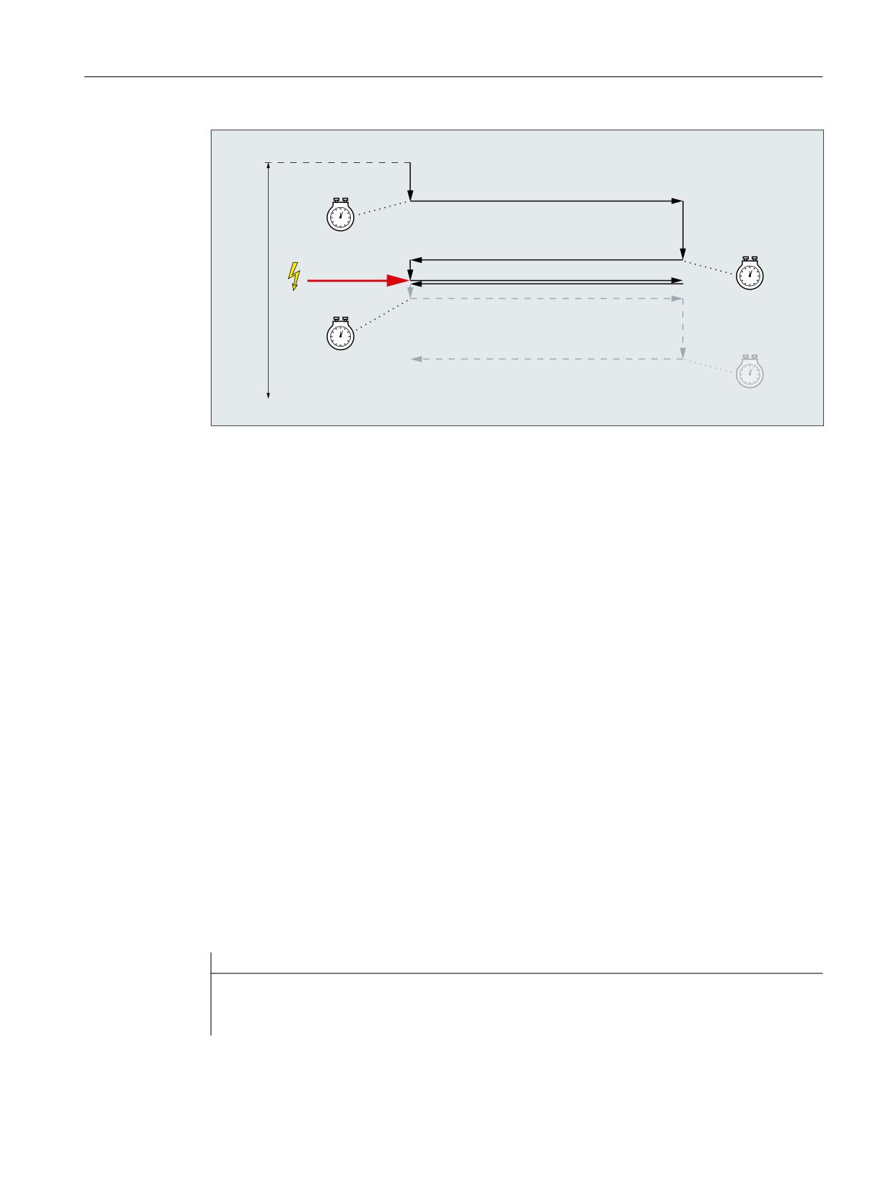
Programming cycles externally
20.1 Technology cycles
6B,!
) 6B5!
6B$!
) 6B)!
6B3!
6B-!
) 6B5!
6B$!
) 6B)!
6B,!
) 6B5!
6B$!
) 6B)!
6B.!
6B3!
6B*$8*(!
6B3!
Figure 20-8
Cancellation of the infeed at the start
Resources
As resources, the cycle uses a block-wide synchronized action and a synchronized action
variable. The synchronized action is determined dynamically from the free area of the
synchronized action range (CUS.DIR - 1 ..., CMA.DIR - 1000 ..., CST.DIR - 1199 ...).
SYG_IS[1] is used as the synchronized action variable.
Examples
Example 1
Oscillation with:
●
0.02 mm infeed depth at the start
●
0.01mm infeed depth at the end
● Total infeed depth 1 mm
●
100 mm stroke
● Infeed feedrate 1 mm/min
● Transverse feedrate 1000 mm/min
●
1 second sparking-out time
● Standard geometry axes
Cancel signal Rapid input 1 ($A_IN[1] )
Program code
N10 T1 D1
N20 CYCLE4077("1",0.02,0.01,1,100,1,1000,1)
N30 M30
Job Planning
Programming Manual, 12/2018, A5E40869460B AB
815

Programming cycles externally
20.1 Technology cycles
Example 2
Oscillation with:
●
0.02 mm infeed depth at the start
●
0.01mm infeed depth at the end
● Total infeed depth 1 mm
●
100 mm stroke
● Infeed feedrate 1 mm/min
● Transverse feedrate 1000 mm/min
●
1 second sparking-out time
● Standard geometry axes
Cancel signal Dual-port RAM variable 20 less than 0.01 ($A_DBR[20] < 0.01)
Program code
N10 T1 D1
N20 CYCLE4077("($A_DBR[20]<0.01)",0.02,0.01,1,100,1,1000,1)
N30 M30
20.1.51
CYCLE4078 - surface grinding with continuous infeed
Syntax
CYCLE4078(<S_I>, <S_J>, <S_K>, <S_A>, <S_F>, <S_P>, <S_A1>, <S_A2>)
Parameters
No.
Parameter
Data type
Meaning
1
<S_I>
REAL
Infeed depth from the start to the end
2
<S_J>
REAL
Infeed depth from the end to the start
3
<S_K>
REAL
Total infeed depth
4
<S_A>
REAL
Grinding width
5
<S_F>
REAL
Feedrate
6
<S_P>
REAL
Sparking-out time
7
<S_A1>
AXIS
Infeed axis (optional)
8
<S_A2>
AXIS
Oscillating axis (optional)
Function
The cycle is used for machining with a total infeed depth P3 <S_K> by means of continuous
infeed. The infeed depths from the start to the end P1 <S_I> and from the end to the start P2
<S_J> can be different.
The positional data P1 to P4 can be negative or positive.
Job Planning
816
Programming Manual, 12/2018, A5E40869460B AB
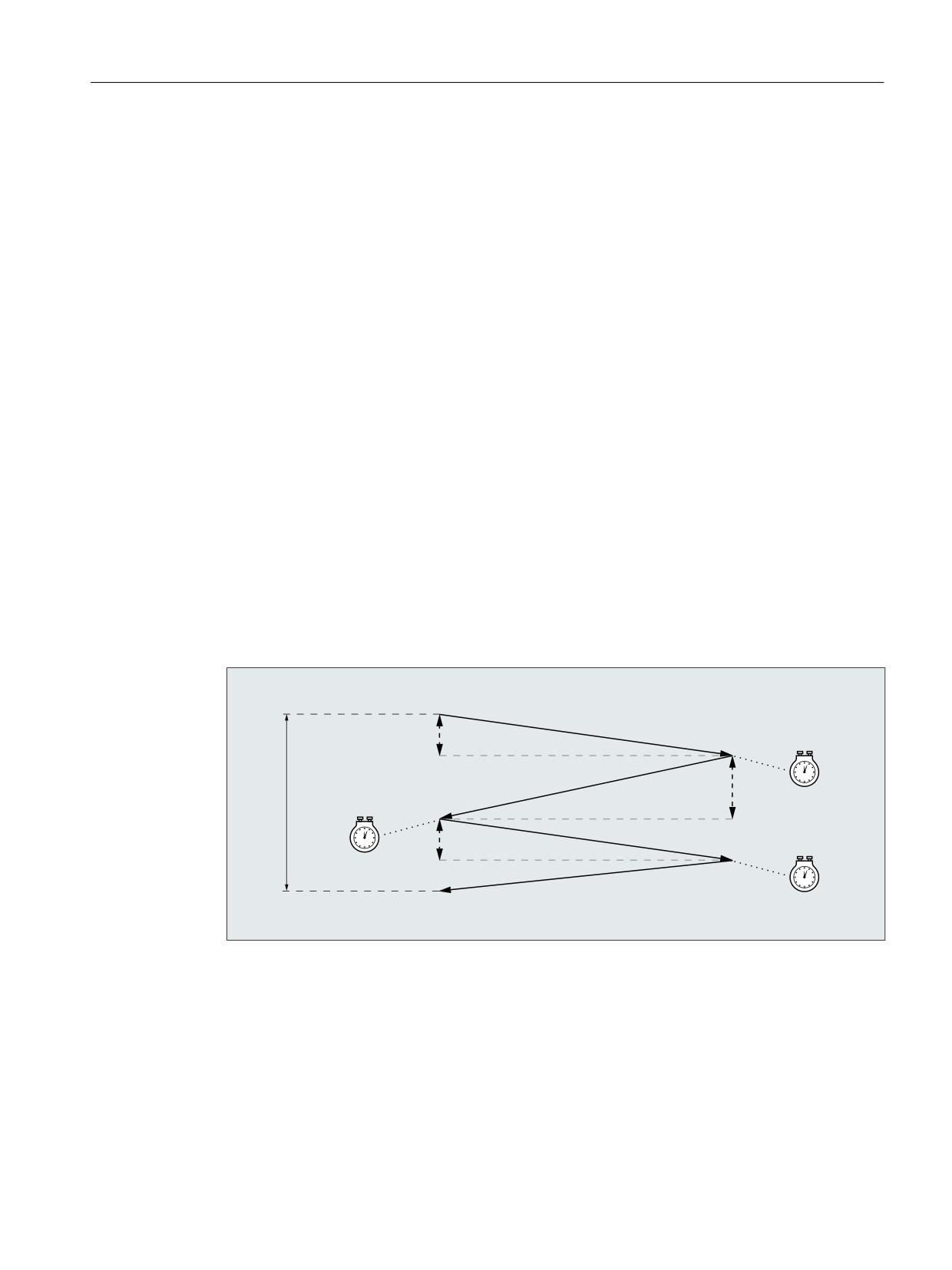
Programming cycles externally
20.1 Technology cycles
The specification of the infeed axis P8 <S_A1> and/or oscillating axis P9 <S_A2> are optional.
If one or both parameters are not specified, the cycle uses the first two geometry axes of the
channel.
If the sum of the infeed depths P1 <S_I> and P2 <S_J> is 0 or the total infeed depth P3
<S_K> is 0, only a sparking-out stroke is performed.
Sequence
1. Start of the cycle at the current position of the oscillating axis with infeed depth 0
2. Traversing of the oscillating axis with the grinding width P4 <S_A> as travel path and
feedrate P5 <S_F> with continuous increase in the infeed depth up to the infeed depth at
the start P1 <S_I>.
3. Sparking out with the sparking-out time P7 <S_P>.
4. Traversing of the oscillating axis with the grinding width P4 <S_A> as travel path to the
starting point and feedrate P5 <S_F> with continuous increase in the infeed depth up to
the infeed depth at the end P2 <S_J>.
5. Sparking out with the sparking-out time P7 <S_P>.
6. Traversing of the oscillating axis with the grinding width P4 <S_A> as travel path to the
starting point and feedrate P5 <S_F>.
The sequence cannot be interrupted with a single block.
The sequence is repeated until the total infeed depth P3 <S_K> has been reached. The last
stroke is then distributed unevenly.
6B,!
6B$!
) 6B)!
6B3!
6B-!
6B.!
6B$!
) 6B)!
6B3!
6B,!
6B$!
) 6B)!
6B3!
6B$!
) 6B)!
Example
Oscillation with:
●
20 mm infeed depth at the start
●
10 mm infeed depth at the end
● Total infeed depth 100 mm
●
100 mm stroke
Job Planning
Programming Manual, 12/2018, A5E40869460B AB
817
Programming cycles externally
20.1 Technology cycles
● Feedrate 1000 mm/min
●
1 second sparking-out time
● Standard geometry axes
Program code
N10 T1 D1
N20 CYCLE4078(20,10,100,100,1000,1)
N30 M30
20.1.52
CYCLE4079 - surface grinding with intermittent infeed
Syntax
CYCLE4079(<S_I>, <S_J>, <S_K>, <S_A>, <S_R>, <S_F>, <S_P>, <S_A1>,
<S_A2>)
Parameters
No.
Parameter
Data type
Meaning
1
<S_I>
REAL
Infeed depth at the start
2
<S_J>
REAL
Infeed depth at the end
3
<S_K>
REAL
Total infeed depth
4
<S_A>
REAL
Grinding width
5
<S_R>
REAL
Feedrate for infeed
6
<S_F>
REAL
Feedrate for transverse infeed
7
<S_P>
REAL
Sparking-out time
8
<S_A1>
AXIS
Infeed axis (optional)
9
<S_A2>
AXIS
Oscillating axis (optional)
Function
The cycle is used for machining with a total infeed depth P3 <S_K> in infeed steps. The infeed
depths at the start P1 <S_I> and at the end P2 <S_J> can be different. There is a tangential
motion between the infeeds.
The positional data P1 to P4 can be negative or positive.
The specification of the infeed axis P8 <S_A1> and/or oscillating axis P9 <S_A2> are optional.
If one or both parameters are not specified, the cycle uses the first two geometry axes of the
channel.
If the sum of the infeed depth at the start P1 <S_I> and at the end P2 <S_J> is 0 or the total
infeed depth P3 <S_K> is 0, only a sparking-out stroke is performed.
Job Planning
818
Programming Manual, 12/2018, A5E40869460B AB
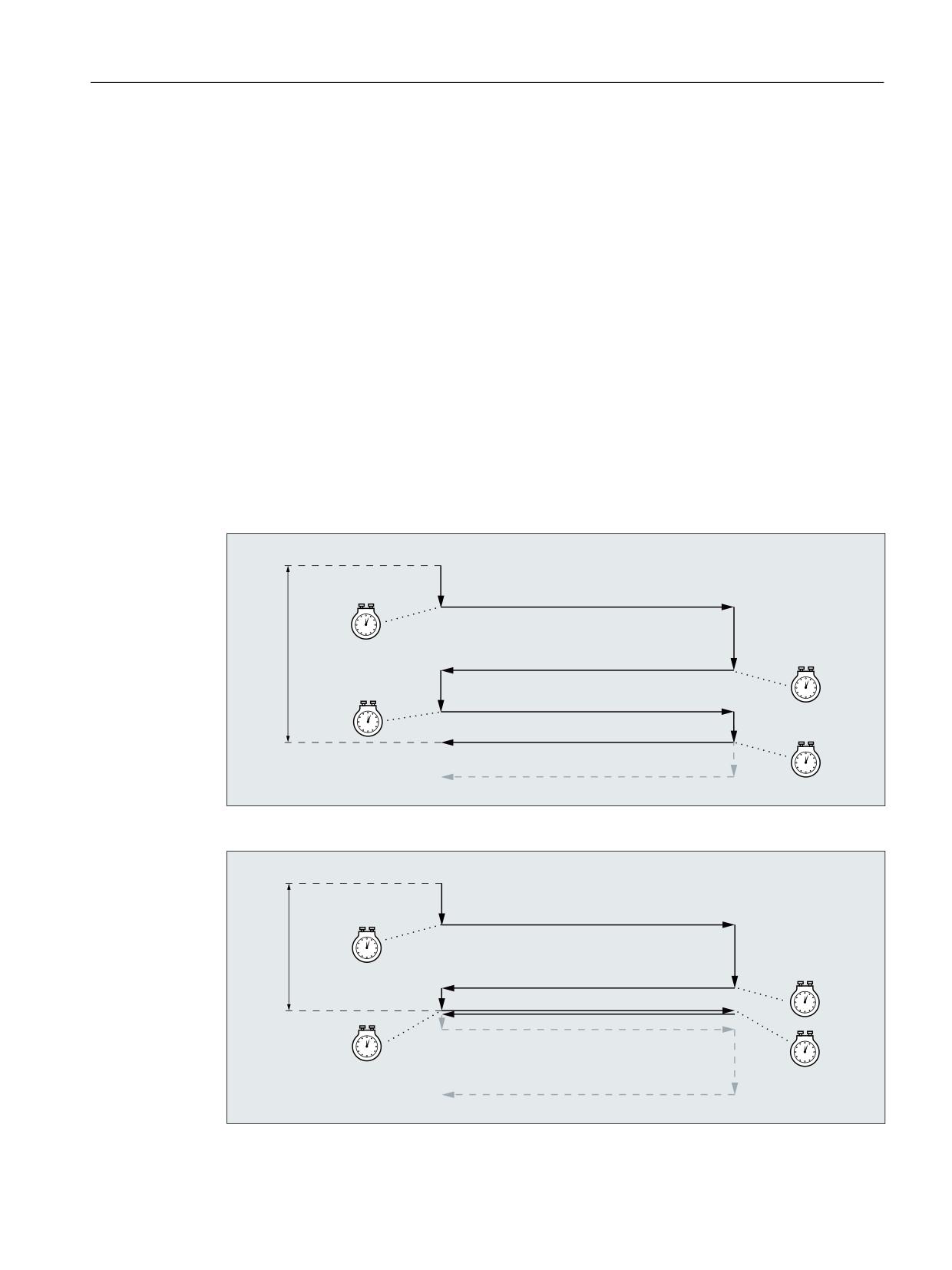
Programming cycles externally
20.1 Technology cycles
Sequence
1. Start of the cycle at the current position of the oscillating axis.
2. Traversing of the infeed axis to the infeed depth at the start P1 <S_I> with the feedrate for
infeed P5 <S_R>.
3. Sparking out with the sparking-out time P7 <S_P>.
4. Traversing of the oscillating axis with the grinding width P4 <S_A> as travel path and the
feedrate for transverse infeed P6 <S_F>.
5. Traversing of the infeed axis to the infeed depth at the end P2 <S_J> with the feedrate for
infeed P5 <S_R>.
6. Sparking out with the sparking-out time P7 <S_P>.
7. Traversing of the oscillating axis with the grinding width P4 <S_A> as travel path to the
starting point and the feedrate for transverse infeed P6 <S_F>.
The sequence cannot be interrupted with a single block.
The sequence is repeated until the total infeed depth P3 <S_K> has been reached. The last
stroke is then distributed unevenly.
6B,!
) 6B5!
6B$!
) 6B)!
6B3!
6B-!
) 6B5!
6B.!
6B$!
) 6B)!
6B,!
) 6B5!
6B3!
6B$!
) 6B)!
6B3!
6B-!
) 6B5!
6B$!
) 6B)!
6B3!
Figure 20-9
Total infeed depth reached with infeed at the second reversal point
6B,!
) 6B5!
6B$!
) 6B)!
6B.!
6B3!
6B-!
) 6B5!
6B$!
) 6B)!
6B,!
) 6B5!
6B$!
) 6B)!
6B3!
6B3!
6B3!
Figure 20-10
Total infeed depth reached with infeed at the first reversal point
Job Planning
Programming Manual, 12/2018, A5E40869460B AB
819
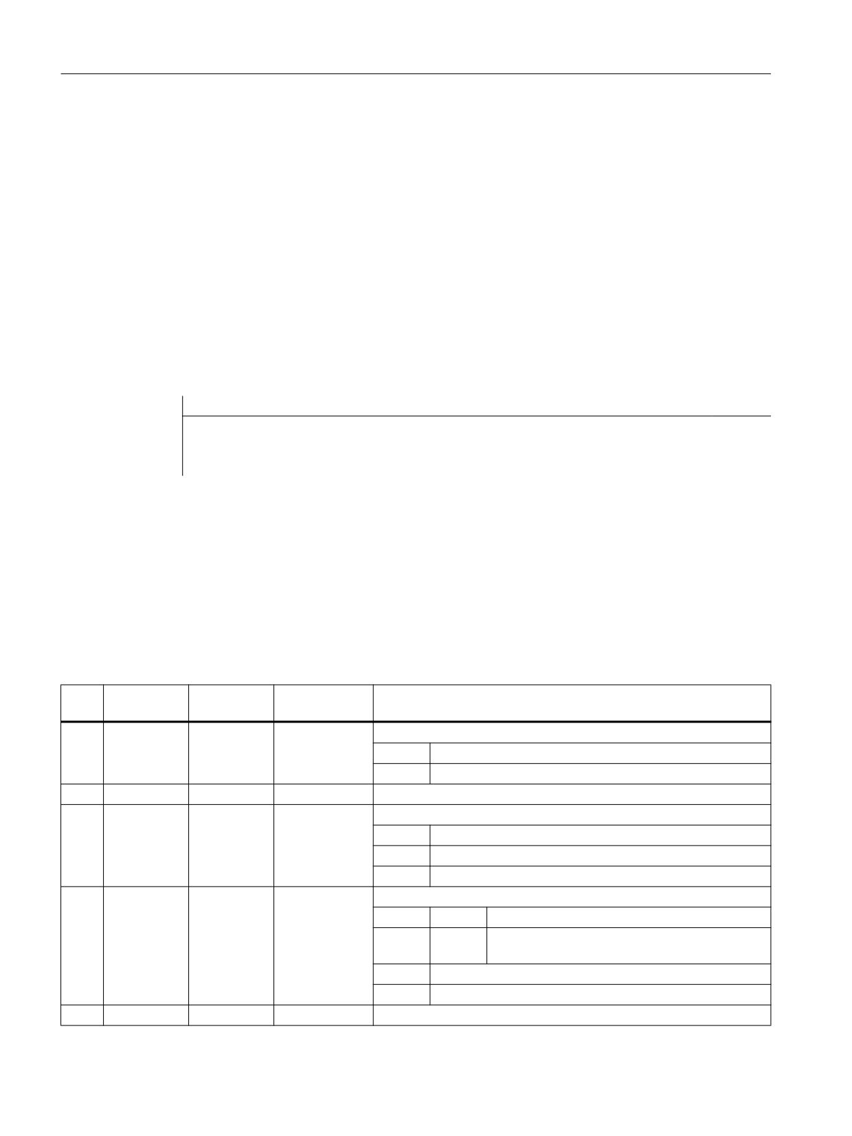
Programming cycles externally
20.1 Technology cycles
Example
Oscillation with:
●
0.02 mm infeed depth at the start
●
0.01mm infeed depth at the end
● Total infeed depth 1 mm
●
100 mm stroke
● Infeed feedrate 1 mm/min
● Transverse feedrate 1000 mm/min
●
1 second sparking-out time
● Standard geometry axes
Program code
N10 T1 D1
N20 CYCLE4079(0.02,0.01,1,100,1,1000,1)
N30 M30
20.1.53
GROUP_BEGIN - beginning of program block
Syntax
GROUP_BEGIN(<_LEVEL>, <_NAME>, <_SP>, <_MODE>, <S_ICON>)
Parameter
No.
Parameter
Parameter
Data type
Meaning
mask
internal
1
<_LEVEL>
INT
Level
0 =
Main level
1 =
1st sublevel
2
<_NAME>
STRING[128]
Block name
3
<_SP>
INT
Spindle
0 =
No spindle
1 =
Main spindle
2 =
Counterspindle
4
<_MODE>
INT
Mode
Bit 0
= 1
GROUP_ADDEND exists
Bit 1
= 1
ShopTurn: Automatic retraction (traverse to tool
change point)
Bit 12
Reserved
Bit 13
Reserved
5
<S_ICON>
STRING[32]
Name of the icon (only for operator interface)
Job Planning
820
Programming Manual, 12/2018, A5E40869460B AB
Programming cycles externally
20.1 Technology cycles
20.1.54
GROUP_END - end of program block
Syntax
GROUP_END(<_LEVEL>, <_SP>)
Parameter
No.
Parameter
Parameter
Data type
Meaning
mask
internal
1
<_LEVEL>
INT
Level
0 =
Main level
1 =
1st sublevel
2
<_SP>
INT
Spindle
0 =
No spindle
1 =
Main spindle
2 =
Counterspindle
20.1.55
GROUP_ADDEND - End of trial cut addition
Syntax
GROUP_ADDEND(<_LEVEL>, <_SP>)
Parameter
No.
Parameter
Parameter
Data type
Meaning
mask
internal
1
<_LEVEL>
INT
Level
0 =
Main level
1 =
1st sublevel
2
<_SP>
INT
Spindle
0 =
No spindle
1 =
Main spindle
2 =
Counterspindle
20.1.56
Supplementary conditions
20.1.56.1
Technology scaling in cycle screen forms
When the technology scaling is active, the simplified input can be selected for various cycle
screen forms, in which only the most important cycle parameters are displayed
Job Planning
Programming Manual, 12/2018, A5E40869460B AB
821
Programming cycles externally
20.1 Technology cycles
For example, the simplified input can be selected for the following cycle screen forms:
Technology
Cycle screen form
Drilling
Deep-hole drilling
Tapping
Milling
Rectangular pocket
Contour milling: Pocket
Turning
Thread turning: Longitudinal
Contour turning: Stock removal
Contour turning: Grooving
Contour turning: Groove turning
In the user interface of the relevant cycle screen forms, the options "Input: Simple" and "Input:
Complete" are available.
Cycle parameters that are not displayed
The cycle parameters that are not displayed in the simplified input are pre-assigned fixed,
technologically useful, but not variable values. Or the cycle parameters are assigned
parameterizable values via the channel-specific cycle setting data. See the paragraph below
"Commissioning" > "Channel-specific cycle setting data"
Switchover from "Input: Complete" > "Input: Simple"
If a cycle screen form is filled in with the setting "Input complete" and then switched to "Input
simple", the default or setting data values are used for the parameters no longer displayed
when generating the cycle call.
Commissioning
Channel-specific configuration machine data
The technology scaling in cycle screen forms can be activated with the machine data:
MD52210 $MCS_FUNCTION_MASK_DISP, bit 9 = 1 (select display "Input simple")
Channel-specific cycle setting data
If the simplified input in cycle screen forms is active, the values for certain cycle parameters
can be specified via the following setting data:
Number
Identifier
Meaning
SD55300
$SCS_EASY_SAFETY_CLEARANCE
Safety clearance
SD55301
$SCS_EASY_DWELL_TIME
Dwell time
SD55305
$SCS_EASY_DRILL_DEEP_FD1
Deep-hole drilling: Percentage: 1st feedrate
SD55306
$SCS_EASY_DRILL_DEEP_DF
Deep-hole drilling: Percentage: Infeed
SD55307
$SCS_EASY_DRILL_DEEP_V1
Deep-hole drilling: Minimum depth infeed
SD55308
$SCS_EASY_DRILL_DEEP_V2
Deep-hole drilling: Retraction distance
SD55309
$SCS_EASY_THREAD_RETURN_DIST
Thread turning: Return distance
Job Planning
822
Programming Manual, 12/2018, A5E40869460B AB
Programming cycles externally
20.2 Measuring cycles
20.2
Measuring cycles
Measuring cycles are special subprograms provided by Siemens to solve certain measuring
tasks. As with cycles in general, measuring cycles can also be adapted to specific problems
via parameter settings.
Measuring cycles are available in the following areas and technologies:
● Tool measurements, turning/milling
● Workpiece measurements, turning/milling
References
For a detailed description of the measuring cycles, refer to:
Measuring Cycles Programming Manual
Job Planning
Programming Manual, 12/2018, A5E40869460B AB
823
Programming cycles externally
20.2 Measuring cycles
Job Planning
824
Programming Manual, 12/2018, A5E40869460B AB
Tables
21
21.1
Operations
Note
Cycles
The list of operations contains all cycles, which occur in the NC program (G code), i.e. can be
programmed in the program editor using masks - or must be programmed for loops without
programming support. Cycles, which for reasons of compatibility, are still available in the
control, however can no longer be edited using the SINUMERIK Operate program editor
("compatibility cycles") are not taken into account.
Operations A ... C
Operation
Type
Meaning
W 2)
TP 3)
SA 4)
Description see 5)
1)
1) 2) 3) 4) 5) for explanations, see legend (Page 860).
:
O
NC main block number, jump label termina-
+
PGAsl
tion, concatenation operator
*
O
Operator for multiplication
+
PGAsl
+
O
Operator for addition
+
PGAsl
-
O
Operator for subtraction
+
PGAsl
<
O
Comparison operator, less than
+
PGAsl
<<
O
Concatenation operator for strings
+
PGAsl
<=
O
Comparison operator, less than or equal to
+
PGAsl
=
O
Assignment operator
+
PGAsl
>=
O
Comparison operator, greater than or equal to
+
PGAsl
/
O
Operator for division
+
PGAsl
/0
block is skipped (1st skip level)
+
PGsl
…
…
block is skipped (8th skip level)
/7
A
A
Axis name
m/s
+
PGAsl
A2
A
Tool orientation: RPY or Euler angle
s
+
PGAsl
A3
A
Tool orientation: 1st component of the direc-
s
+
PGAsl
tion vector
A4
A
Tool orientation: 1st component of the surface
s
+
PGAsl
normal vector at start of block
A5
A
Tool orientation: 1st component of the surface
s
+
PGAsl
normal vector at end of block
A6
A
Tool orientation: 1st component of the direc-
s
+
PGAsl
tion vector for taper's axis of rotation
Job Planning
Programming Manual, 12/2018, A5E40869460B AB
825
Tables
21.1 Operations
Operation
Type
Meaning
W 2)
TP 3)
SA 4)
Description see 5)
1)
1) 2) 3) 4) 5) for explanations, see legend (Page 860).
A7
A
Tool orientation: 1st Vector component for in-
s
+
PGAsl
termediate orientation on peripheral surface
of taper
ABS
F
Absolute value (amount)
+
+
PGAsl
AC
K
Absolute dimensions of coordinates/positions
s
+
PGsl
ACC
K
Effect of current axial acceleration
m
+
+
PGsl
ACCLIMA
K
Effect of current maximum axial acceleration
m
+
+
PGAsl
ACN
K
Absolute dimensions for rotary axes, ap-
s
+
PGsl
proach position in negative direction
ACOS
F
Arc cosine
+
+
PGAsl
(trigon. function)
ACP
K
Absolute dimensions for rotary axes, ap-
s
+
PGsl
proach position in positive direction
ACTBLOCNO
P
Output of current block number of an alarm
+
PGAsl
block, even if "current block display sup-
pressed" (DISPLOF) is active!
ADDFRAME
F
Inclusion and possible activation of a meas-
+
-
PGAsl, FB1sl (K2)
ured frame
ADIS
A
Rounding clearance for path functions G1,
m
+
PGsl
G2, G3, ...
ADISPOS
A
Rounding clearance for rapid traverse G0
m
+
PGsl
ADISPOSA
P
Size of the tolerance window for IPOBRKA
m
+
+
PGAsl
ALF
A
LIFTFAST angle
m
+
PGAsl
AMIRROR
G
Programmable mirroring
s
+
PGsl
AND
K
Logical AND
+
PGAsl
ANG
A
Contour angle
s
+
PGsl
AP
A
Polar angle
m/s
+
PGsl
APR
K
Read/show access protection
+
PGAsl
APRB
K
Read access right, OPI
+
PGAsl
APRP
K
Read access right, part program
+
PGAsl
APW
K
Write access protection
+
PGAsl
APWB
K
Write access right, OPI
+
PGAsl
APWP
K
Write access right, part program
+
PGAsl
APX
K
Definition of the access right for executing the
+
PGAsl
specified language element
AR
A
Opening angle
m/s
+
PGsl
AROT
G
Programmable rotation
s
+
PGsl
AROTS
G
Programmable frame rotations with solid an-
s
+
PGsl
gles
AS
K
Macro definition
+
PGAsl
ASCALE
G
Programmable scaling
s
+
PGsl
ASIN
F
Arithmetic function, arc sine
+
+
PGAsl
ASPLINE
G
Akima spline
m
+
PGAsl
Job Planning
826
Programming Manual, 12/2018, A5E40869460B AB
Tables
21.1 Operations
Operation
Type
Meaning
W 2)
TP 3)
SA 4)
Description see 5)
1)
1) 2) 3) 4) 5) for explanations, see legend (Page 860).
ATAN2
F
Arc tangent 2
+
+
PGAsl
ATOL
A
Axis-specific tolerance for compressor func-
m
+
PGAsl
tions, orientation smoothing and smoothing
types
ATRANS
G
Additive programmable work offset
s
+
PGsl
AUXFUDEL
P
Delete auxiliary function channel-specifically
+
-
FB1sl (H2)
from the global list
AUXFUDELG
P
Delete all auxiliary functions of an auxiliary
+
-
FB1sl (H2)
function group channel-specifically from the
global list
AUXFUMSEQ
P
Determine output sequence of M auxiliary
+
-
FB1sl (H2)
functions
AUXFUSYNC
P
Generate a complete part program block for
+
-
FB1sl (H2)
the channel-specific SERUPRO end ASUB as
string from the global list of auxiliary functions
AX
K
Variable axis identifier
m/s
+
PGAsl
AXCTSWE
P
Rotate axis container
+
-
PGAsl
AXCTSWEC
P
Canceling enable for axis container rotation
+
+
PGAsl
AXCTSWED
P
Rotating axis container (command variant for
+
-
PGAsl
commissioning!)
AXIS
K
Axis identifier, axis address
+
PGAsl
AXNAME
F
Converts input string into axis identifier
+
-
PGAsl
AXSTRING
F
Converts string spindle number
+
-
PGAsl
AXTOCHAN
P
Request axis for a specific channel. Possible
+
+
PGAsl
from NC program and synchronized action.
AXTOSPI
F
Converts axis identifier into a spindle index
+
-
PGAsl
B
A
Axis name
m/s
+
PGAsl
B2
A
Tool orientation: RPY or Euler angle
s
+
PGAsl
B3
A
Tool orientation: 2nd component of the direc-
s
+
PGAsl
tion vector
B4
A
Tool orientation: 2nd component of the sur-
s
+
PGAsl
face normal vector at start of block
B5
A
Tool orientation: 2nd component of the sur-
s
+
PGAsl
face normal vector at end of block
B6
A
Tool orientation: 2nd component of the direc-
s
+
PGAsl
tion vector for taper's axis of rotation
B7
A
Tool orientation: 2nd Vector component for in-
s
+
PGAsl
termediate orientation on peripheral surface
of taper
B_AND
O
Bit-by-bit AND
+
PGAsl
B_OR
O
Bit-by-bit OR
+
PGAsl
B_NOT
O
Bit-by-bit negation
+
PGAsl
B_XOR
O
Bit-by-bit exclusive OR
+
PGAsl
BAUTO
G
Definition of the first spline section by means
m
+
PGAsl
of the next 3 points
Job Planning
Programming Manual, 12/2018, A5E40869460B AB
827
Tables
21.1 Operations
Operation
Type
Meaning
W 2)
TP 3)
SA 4)
Description see 5)
1)
1) 2) 3) 4) 5) for explanations, see legend (Page 860).
BLOCK
K
Together with the keyword TO defines the pro-
+
PGAsl
gram part to be processed in an indirect sub-
program call
BLSYNC
K
Processing of interrupt routine is only to start
+
PGAsl
with the next block change
BNAT 6)
G
Natural transition to first spline block
m
+
PGAsl
BOOL
K
Data type: Boolean value TRUE/FALSE or 1/0
+
PGAsl
BOUND
F
Tests whether the value falls within the de-
+
+
PGAsl
fined value range. If the values are equal, the
test value is returned.
BRISK 6)
G
Fast non-smoothed path acceleration
m
+
PGAsl
BRISKA
P
Switch on brisk path acceleration for the pro-
+
-
PGAsl
grammed axes
BSPLINE
G
B spline
m
+
PGAsl
BTAN
G
Tangential transition to first spline block
m
+
PGAsl
C
A
Axis name
m/s
+
PGAsl
C2
A
Tool orientation: RPY or Euler angle
s
+
PGAsl
C3
A
Tool orientation: 3rd component of the direc-
s
+
PGAsl
tion vector
C4
A
Tool orientation: 3rd component of the surface
s
+
PGAsl
normal vector at start of block
C5
A
Tool orientation: 3rd component of the surface
s
+
PGAsl
normal vector at end of block
C6
A
Tool orientation: 3rd component of the direc-
s
+
PGAsl
tion vector for taper's axis of rotation
C7
A
Tool orientation: 3rd Vector component for in-
s
+
PGAsl
termediate orientation on peripheral surface
of taper
CAC
K
Absolute position approach
+
PGAsl
CACN
K
Absolute approach of the value listed in the
+
PGAsl
table in negative direction
CACP
K
Absolute approach of the value listed in the
+
PGAsl
table in positive direction
CALCDAT
F
Calculates radius and center point of circle
+
-
PGAsl
from 3 or 4 points
CALCPOSI
F
Checking for protection area violation, work-
+
-
PGAsl
ing area limitation and software limits
CALL
K
Indirect subprogram call
+
PGAsl
CALLPATH
P
Programmable search path for subprogram
+
-
PGAsl
calls
CANCEL
P
Cancel modal synchronized action
+
-
FBSYsl
CASE
K
Conditional program branch
+
PGAsl
CDC
K
Direct approach of a position
+
PGAsl
CDOF 6)
G
Switch off collision monitoring
m
+
PGsl
Job Planning
828
Programming Manual, 12/2018, A5E40869460B AB
Tables
21.1 Operations
Operation
Type
Meaning
W 2)
TP 3)
SA 4)
Description see 5)
1)
1) 2) 3) 4) 5) for explanations, see legend (Page 860).
CDOF2
G
Switch off collision monitoring during 3D cir-
m
+
PGsl
cumferential milling
CDON
G
Activate collision monitoring
m
+
PGsl
CFC 6)
G
Constant feedrate on contour
m
+
PGsl
CFIN
G
Constant feedrate for internal radius only, not
m
+
PGsl
for external radius
CFINE
F
Assignment of fine offset to a FRAME variable
+
-
PGAsl
CFTCP
G
Constant feedrate in tool center point (center
m
+
PGsl
point path)
CHAN
K
Specify validity range for data
+
PGAsl
CHANDATA
P
Set channel number for channel data access
+
-
PGAsl
CHAR
K
Data type: ASCII character
+
PGAsl
CHF
A
Chamfer;
s
+
PGsl
value = length of chamfer
CHKDM
F
Uniqueness check within a magazine
+
-
FBWsl
CHKDNO
F
Check for unique D numbers
+
-
PGAsl
CHR
A
Chamfer;
+
PGsl
value = length of chamfer in direction of move-
ment
CIC
K
Approach position by increments
+
PGAsl
CIP
G
Circular interpolation through intermediate
m
+
PGsl
point
CLEARM
P
Reset one/several markers for channel coor-
+
+
PGAsl
dination
CLRINT
P
Deselect interrupt
+
-
PGAsl
CMIRROR
F
Mirror on a coordinate axis
+
-
PGAsl
COARSEA
K
Motion end when "Exact stop coarse" reached
m
+
PGAsl
COLLPAIR
F
Check whether part of a collision pair
+
PGAsl
COMPCAD
G
Activate the compressor function COMPCAD
m
+
PGAsl
COMPCURV
G
Activate the compressor function COMP-
m
+
PGAsl
CURV
COMPLETE
Control instruction for reading and writing data
+
PGAsl
COMPOF 6)
G
Deactivate NC block compression
m
+
PGAsl
COMPON
G
Activate the compressor function COMPON
m
+
PGAsl
COMPSURF
G
Activate the compressor function COMPSURF
m
+
PGAsl
CONTDCON
P
Activate tabular contour decoding
+
-
PGAsl
CONTPRON
P
Activate reference preprocessing
+
-
PGAsl
CORROF
P
All active overlaid movements are deselected.
+
-
PGsl
CORRTRAFO
F
Modifying offset vectors or direction vectors
+
-
PGAsl
for the orientation axes in the kinematic model
of the machine
COS
F
Cosine
+
+
PGAsl
(trigon. function)
Job Planning
Programming Manual, 12/2018, A5E40869460B AB
829
Tables
21.1 Operations
Operation
Type
Meaning
W 2)
TP 3)
SA 4)
Description see 5)
1)
1) 2) 3) 4) 5) for explanations, see legend (Page 860).
COUPDEF
P
Definition ELG group/synchronous spindle
+
-
PGAsl
group
COUPDEL
P
Delete ELG group
+
-
PGAsl
COUPOF
P
Deactivate ELG group / synchronous spindle
+
-
PGAsl
pair
COUPOFS
P
Deactivate ELG group/synchronous spindle
+
-
PGAsl
pair with stop of following spindle
COUPON
P
Activate ELG group / synchronous spindle pair
+
-
PGAsl
COUPONC
P
Transfer activation of ELG group/synchro-
+
-
PGAsl
nous spindle pair with previous programming
COUPRES
P
Reset ELG group
+
-
PGAsl
CP 6)
G
Path motion
m
+
PGAsl
CPBC
K
Generic coupling: Block change criterion
+
+
FB3sl (M3)
CPDEF
K
Generic coupling: Creating a coupling module
+
+
FB3sl (M3)
CPDEL
K
Generic coupling: Deletion of a coupling mod-
+
+
FB3sl (M3)
ule
CPFMOF
K
Generic coupling: Behavior of the following
+
+
FB3sl (M3)
axis at complete switch-off
CPFMON
K
Generic coupling: Behavior of the following
+
+
FB3sl (M3)
axis when switching on
CPFMSON
K
Generic coupling: Synchronization mode
+
+
FB3sl (M3)
CPFPOS
K
Generic coupling: Synchronized position of
+
+
FB3sl (M3)
the following axis
CPFRS
K
Generic coupling: Coordinate reference sys-
+
+
FB3sl (M3)
tem
CPLA
K
Generic coupling: Definition of a leading axis
+
-
FB3sl (M3)
CPLCTID
K
Generic coupling: Number of the curve table
+
+
FB3sl (M3)
CPLDEF
K
Generic coupling: Definition of a leading axis
+
+
FB3sl (M3)
and creation of a coupling module
CPLDEL
K
Generic coupling: Deleting a leading axis of a
+
+
FB3sl (M3)
coupling module
CPLDEN
K
Generic coupling: Denominator of the cou-
+
+
FB3sl (M3)
pling factor
CPLINSC
K
Generic coupling: Scaling factor of the input
+
+
FB3sl (M3)
value of a leading axis
CPLINTR
K
Generic coupling: Offset value of the input val-
+
+
FB3sl (M3)
ue of a leading axis
CPLNUM
K
Generic coupling: Numerator of the coupling
+
+
FB3sl (M3)
factor
CPLOF
K
Generic coupling: Switching off a leading axis
+
+
FB3sl (M3)
of a coupling module
CPLON
K
Generic coupling: Switching on a leading axis
+
+
FB3sl (M3)
of a coupling module
CPLOUTSC
K
Generic coupling: Scaling factor for the output
+
+
FB3sl (M3)
value of a coupling
Job Planning
830
Programming Manual, 12/2018, A5E40869460B AB
Tables
21.1 Operations
Operation
Type
Meaning
W 2)
TP 3)
SA 4)
Description see 5)
1)
1) 2) 3) 4) 5) for explanations, see legend (Page 860).
CPLOUTTR
K
Generic coupling: Offset value for the output
+
+
FB3sl (M3)
value of a coupling
CPLPOS
K
Generic coupling: Synchronized position of
+
+
FB3sl (M3)
the leading axis
CPLSETVAL
K
Generic coupling: Coupling reference
+
+
FB3sl (M3)
CPMALARM
K
Generic coupling: Suppression of special cou-
+
+
FB3sl (M3)
pling-related alarm outputs
CPMBRAKE
K
Generic coupling: Response of the following
+
-
FB3sl (M3)
axis to certain stop signals and stop com-
mands
CPMPRT
K
Generic coupling: Coupling response at part
+
+
FB3sl (M3)
program start under block search run via pro-
gram test
CPMRESET
K
Generic coupling: Coupling behavior for RE-
+
+
FB3sl (M3)
SET
CPMSTART
K
Generic coupling: Coupling behavior at part
+
+
FB3sl (M3)
program start
CPMVDI
K
Generic coupling: Response of the following
+
+
FB3sl (M3)
axis to certain NC/PLC interface signals
CPOF
K
Generic coupling: Switching off a coupling
+
+
FB3sl (M3)
module
CPON
K
Generic coupling: Switching on a coupling
+
+
FB3sl (M3)
module
CPRECOF 6)
G
Deactivate programmable contour accuracy
m
+
PGAsl
CPRECON
G
Activate programmable contour accuracy
m
+
PGAsl
CPRES
K
Generic coupling: Activates the configured da-
+
-
FB3sl (M3)
ta of the synchronous spindle coupling
CPROT
P
Activate / deactivate channel-specific protec-
+
-
PGAsl
tion zone
CPROTDEF
P
Definition of a channel-specific protection area
+
-
PGAsl
CPSETTYPE
K
Generic coupling: Coupling type
+
+
FB3sl (M3)
CPSYNCOP
K
Generic coupling: Threshold value of position
+
+
FB3sl (M3)
synchronism "Coarse"
CPSYNCOP2
K
Generic coupling: Threshold value of position
+
+
FB3sl (M3)
synchronism "Coarse" 2
CPSYNCOV
K
Generic coupling: Threshold value of velocity
+
+
FB3sl (M3)
synchronism "Coarse"
CPSYNFIP
K
Generic coupling: Threshold value of position
+
+
FB3sl (M3)
synchronism "Fine"
CPSYNFIP2
K
Generic coupling: Threshold value of position
+
+
FB3sl (M3)
synchronism "Fine" 2
CPSYNFIV
K
Generic coupling: Threshold value of velocity
+
+
FB3sl (M3)
synchronism "Fine"
CR
A
Circle radius
s
+
PGsl
CROT
F
Rotation of the current coordinate system
+
-
PGAsl
Job Planning
Programming Manual, 12/2018, A5E40869460B AB
831
Tables
21.1 Operations
Operation
Type
Meaning
W 2)
TP 3)
SA 4)
Description see 5)
1)
1) 2) 3) 4) 5) for explanations, see legend (Page 860).
CROTS
F
Programmable frame rotations with solid an-
s
+
-
PGsl
gles (rotation in the specified axes)
CRPL
F
Frame rotation in any plane
+
-
FB1sl (K2)
CSCALE
F
Scale factor for multiple axes
+
-
PGAsl
CSPLINE
F
Cubic spline
m
+
PGAsl
CT
G
Circle with tangential transition
m
+
PGsl
CTAB
F
Define following axis position according to
+
+
PGAsl
leading axis position from curve table
CTABDEF
P
Activate table definition
+
-
PGAsl
CTABDEL
P
Clear curve table
+
-
PGAsl
CTABEND
P
Deactivate table definition
+
-
PGAsl
CTABEXISTS
F
Checks the curve table with number n
+
+
PGAsl
CTABFNO
F
Number of curve tables still possible in the
+
+
PGAsl
memory
CTABFPOL
F
Number of polynomials still possible in the
+
+
PGAsl
memory
CTABFSEG
F
Number of curve segments still possible in the
+
+
PGAsl
memory
CTABID
F
Returns table number of the nth curve table
+
+
PGAsl
CTABINV
F
Define leading axis position according to fol-
+
+
PGAsl
lowing axis position from curve table
CTABISLOCK
F
Returns the lock state of the curve table with
+
+
PGAsl
number n
CTABLOCK
P
Delete and overwrite, lock
+
+
PGAsl
CTABMEMTYP
F
Returns the memory in which curve table num-
+
+
PGAsl
ber n is created.
CTABMPOL
F
Max. number of polynomials still possible in
+
+
PGAsl
the memory
CTABMSEG
F
Max. number of curve segments still possible
+
+
PGAsl
in the memory
CTABNO
F
Number of defined curve tables in SRAM or
+
+
FB3sl (M3)
DRAM
CTABNOMEM
F
Number of defined curve tables in SRAM or
+
+
PGAsl
DRAM
CTABPERIOD
F
Returns the table periodicity of curve table
+
+
PGAsl
number n
CTABPOL
F
Number of polynomials already used in the
+
+
PGAsl
memory
CTABPOLID
F
Number of the curve polynomials used by the
+
+
PGAsl
curve table with number n
CTABSEG
F
Number of curve segments already used in
+
+
PGAsl
the memory
CTABSEGID
F
Number of the curve segments used by the
+
+
PGAsl
curve table with number n
Job Planning
832
Programming Manual, 12/2018, A5E40869460B AB
Tables
21.1 Operations
Operation
Type
Meaning
W 2)
TP 3)
SA 4)
Description see 5)
1)
1) 2) 3) 4) 5) for explanations, see legend (Page 860).
CTABSEV
F
Returns the final value of the following axis of
+
+
PGAsl
a segment of the curve table
CTABSSV
F
Returns the initial value of the following axis
+
+
PGAsl
of a segment of the curve table
CTABTEP
F
Returns the value of the leading axis at curve
+
+
PGAsl
table end
CTABTEV
F
Returns the value of the the following axis at
+
+
PGAsl
curve table end
CTABTMAX
F
Returns the maximum value of the following
+
+
PGAsl
axis of the curve table
CTABTMIN
F
Returns the minimum value of the following
+
+
PGAsl
axis of the curve table
CTABTSP
F
Returns the value of the leading axis at curve
+
+
PGAsl
table start
CTABTSV
F
Returns the value of the following axis at curve
+
+
PGAsl
table start
CTABUNLOCK
P
Revoke delete and overwrite lock
+
+
PGAsl
CTOL
A
Contour tolerance for compressor functions,
m
+
PGAsl
orientation smoothing and smoothing types
CTRANS
F
Zero offset for multiple axes
+
-
PGAsl
CUT2D 6)
G
2D TRC
m
+
PGsl
CUT2DD
G
2½ D TRC in relation to the differential tool
m
+
PGsl
CUT2DF
G
2 D TRC relative to the current frame (inclined
m
+
PGsl
plane)
CUT2DFD
G
2½ D TRC in relation to the differential tool
m
+
PGsl
relative to the current frame (inclined plane)
CUT3DC
G
3D TRC for circumferential milling
m
+
PGAsl
CUT3DCC
G
3D TRC for circumferential milling taking into
m
+
PGAsl
account a limitation surface with 3D radius
compensation Contour on the machining sur-
face
CUT3DCCD
G
3D TRC for circumferential milling taking into
m
+
PGAsl
account a limitation surface with differential
tool on the tool center point path Infeed to the
limitation surface.
CUT3DCD
G
3D TRC in relation to a differential tool for cir-
m
+
PGAsl
cumferential milling
CUT3DF
G
3D TRC for face milling with change in orien-
m
+
PGAsl
tation
CUT3DFD
G
3D TRC in relation to a differential tool for face
m
+
PGAsl
milling with change in orientation
CUT3DFF
G
3D TRC for face milling with constant orienta-
m
+
PGAsl
tion. The tool orientation is the direction de-
fined by G17 - G19 and, in some cases, rota-
ted by a frame.
Job Planning
Programming Manual, 12/2018, A5E40869460B AB
833