SINUMERIK 840D sl/828D. Job Planning. Programming Manual (2010-2018) - page 10
Additional functions
18.1 Axis functions (AXNAME, AX, SPI, AXTOSPI, ISAXIS, AXSTRING, MODAXVAL)
Example 4: MODAXVAL
If the programmed axis identifier does not refer to a modulo rotary axis, then the value to be
converted (<axis position>) is returned unchanged.
Program code
Comment
R11=MODAXVAL(X,372.55)
; X is a linear axis; R11 = 372.55.
Job Planning
Programming Manual, 12/2018, A5E40869460B AB
627
Additional functions
18.2 Replaceable geometry axes (GEOAX)
18.2
Replaceable geometry axes (GEOAX)
The "Switchable geometry axes" function allows the geometry axes configured via machine
data to be replaced by other channel axes.
Syntax
GEOAX(<n>,<channel axis>,<n>,<channel axis>,<n>,<channel axis>)
GEOAX()
Meaning
GEOAX(...)
Function for switching geometry axes.
Note:
GEOAX() without parameter specification activates the basic configuration of
the geometry axes parameterized in the machine data again.
<n>
Number of the geometry axis that is to be replaced by the specified channel axis.
Range of values:
0, 1, 2, 3
Note:
0: The specified channel axis is removed from the geometry axis group without
being replaced
1: 1. geometry axis ≙ coordinate axis X (abscissa) of the WCS
2: 2. geometry axis ≙ coordinate axis Y (ordinate) of the WCS
3: 3. geometry axis ≙ coordinate axis Z (applicate) of the WCS
<channel axis>
Name of the channel axis which is to added to the geometry axis group
Examples
Example 1: Switching two axes alternating as geometry axis
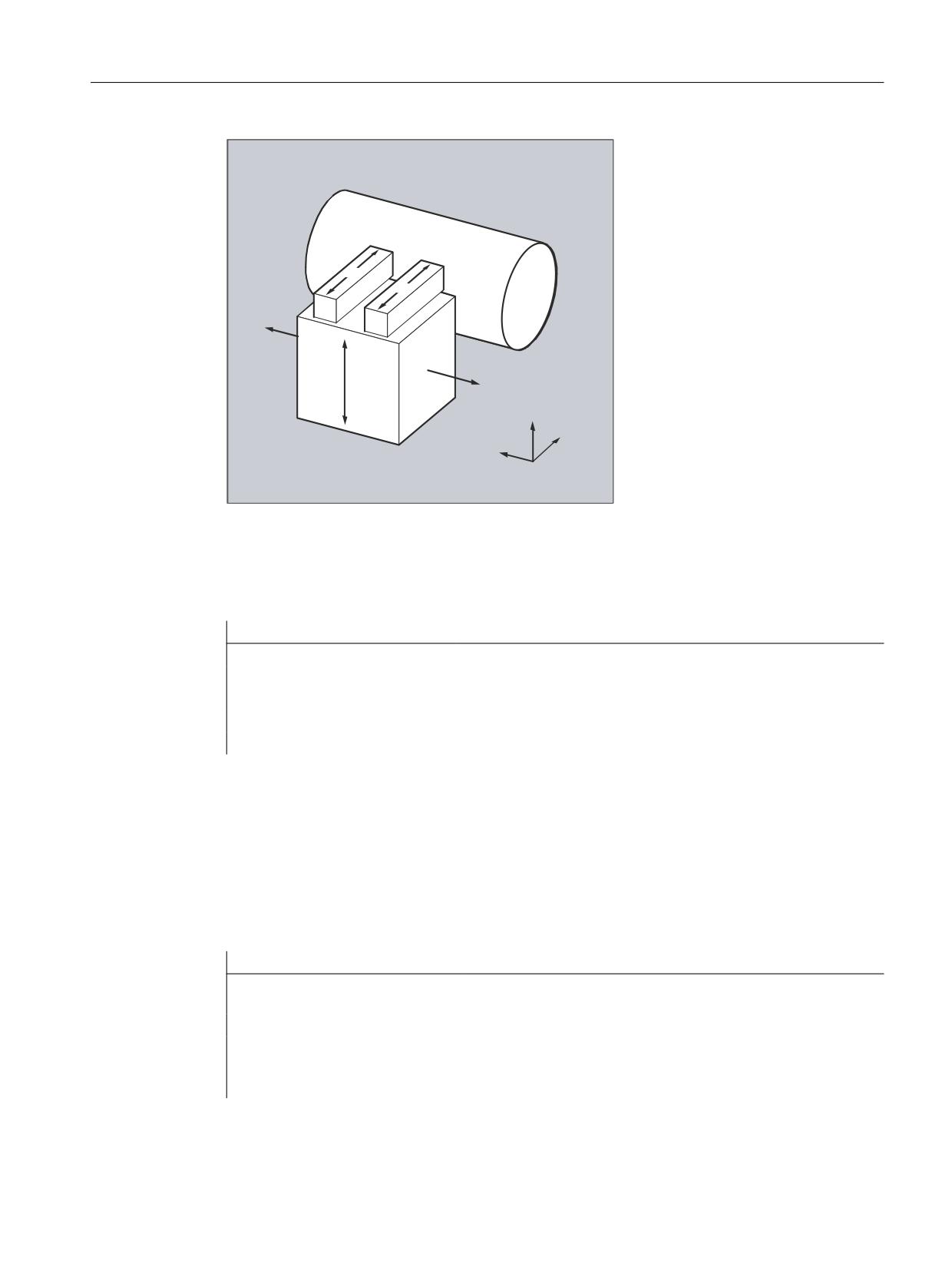
A tool slide can be traversed using channel axes X1, Y1, Z1, Z2:
Job Planning
628
Programming Manual, 12/2018, A5E40869460B AB
Additional functions
18.2 Replaceable geometry axes (GEOAX)
=
=
<
;
<
=
;
The geometry axes are configured so that after powering-up, initially Z1 is effective as 3rd
geometry axis under the geometry axis name "Z" and together with X1 and Y1 forms the
geometry axis group.
Axes Z1 and Z2 should now be used, alternating, as geometry axis Z in the part program:
Program code
Comment
N100 GEOAX(3,Z2)
; Channel axis Z2 acts as 3rd geometry axis (Z).
N110 G1 ...
N120 GEOAX(3,Z1)
; Channel axis Z1 acts as 3rd geometry axis (Z).
Example 2: Changing over the geometry axes for six channel axes
A machine has six channel axes with the names XX, YY, ZZ, U, V, W.
The basic setting of the geometry axis configuration via machine data is:
Channel axis XX = 1st geometry axis (X axis)
Channel axis YY = 2nd geometry axis (Y axis)
Channel axis ZZ = 3rd geometry axis (Z axis)
Program code
Comment
N10 GEOAX()
; The basic configuration of the geometry axes is ef-
fective.
N20 G0 X0 Y0 Z0 U0 V0 W0
; All axes in rapid traverse to position 0.
N30 GEOAX(1,U,2,V,3,W)
; Channel axis U becomes the first (X), V the second
(Y)
; and W the third geometry axis (Z).
Job Planning
Programming Manual, 12/2018, A5E40869460B AB
629
Additional functions
18.2 Replaceable geometry axes (GEOAX)
Program code
Comment
N40 GEOAX(1,XX,3,ZZ)
; Channel axis XX becomes the first (X), ZZ the third
; geometry axis (Z). Channel axis V remains the second
; geometry axis (Y).
N50 G17 G2 X20 I10 F1000
; Full circle in the X/Y plane. Channel axes
; XX and V traverse.
N60 GEOAX(2,W)
; Channel axis W becomes the second geometry (Y).
N80 G17 G2 X20 I10 F1000
; Full circle in the X/Y plane. Channel axes
; XX and W traverse.
N90 GEOAX()
; Reset to the initial state.
N100 GEOAX(1,U,2,V,3,W)
; Channel axis U becomes the first (X), V the second
; (Y) and W the third geometry axis (Z).
N110 G1 X10 Y10 Z10 XX=25
; Channel axes U, V, W each traverse to
; position 10. XX as special axis traverses to posi-
tion 25.
N120 GEOAX(0,V)
; V is removed from the geometry axis group.
; U and W remain the first (X) and third
; geometry axis (Z).
; The second geometry (Y) axis remains unassigned.
N130 GEOAX(1,U,2,V,3,W)
; Channel axis U remains the first (X), V becomes
; the second (Y), W remains the third geometry axis
(Z).
N140 GEOAX(3,V)
; V becomes the third geometry axis (Z), whereby W
; is overwritten and therefore removed from the geom-
etry
; axis group. The second geometry axis (Y)
; still remains unassigned.
Machine data
Axis configuration
Assignment of geometry, special and machine axes to channel axes:
● MD10000 $MN_AXCONF_MACHAX_NAME_TAB
● MD20050 $MC_AXCONF_GEOAX_ASIGN_TAB
● MD20060 $MC_AXCONF_GEOAX_NAME_TAB
● MD20070 $MC_AXCONF_MACHAX_USED
● MD20080 $MC_AXCONF_CHANAX_NAME_TAB
● MD35000 $MA_SPIND_ASSIGN_TO_MACHAX
Reset behavior
Reset behavior of changed geometry axis assignments:
● MD20110 $MC_RESET_MODE_MASK, bit 12
● MD20118 $MC_GEOAX_CHANGE_RESET
Job Planning
630
Programming Manual, 12/2018, A5E40869460B AB
Additional functions
18.2 Replaceable geometry axes (GEOAX)
NC start behavior
● MD20112 $MC_START_MODE_MASK, bit 12
Notification to the PLC user program
Parameterization option of the M command which is output on the NC/PLC interface when the
geometry axes are changed.
● MD22532 $MC_GEOAX_CHANGE_M_CODE
Supplementary conditions
No geometry axis changeover
● If one of the following functions is active, a geometry axis changeover is not possible:
- Transformation
- Spline interpolation
- Tool radius compensation
- Tool fine offset
● The geometry axis and another channel axis have the same name.
● One of the axes participating in the geometry axis changeover is involved in an action that
goes beyond block limits, e.g. block-wide positioning axis or following axis of an axis
coupling.
Rotary axes
Rotary axes cannot be programmed as geometry axes.
Axis state after replacing
An axis replaced by the changeover in the geometry axis group can be programmed as
supplementary axis after the changeover operation via its channel axis names.
Frames, protection areas, working area limits
All frames, protection areas and working area limits are deleted after changing over the
geometry axes.
Polar coordinates
Replacing the geometry axes with GEOAX sets analog to a level change with G17-G19, the
modal polar coordinates to a value of 0.
DRF, WO
A possible handwheel offset (DRF) or an external work offset (WO) remains effective after the
changeover.
Basic configuration of the geometry axes
The GEOAX() command calls the basic configuration of the geometry axis group.
The system automatically changes back to the basic configuration after POWER ON and when
changing over into the "reference point approach" mode.
Job Planning
Programming Manual, 12/2018, A5E40869460B AB
631
Additional functions
18.2 Replaceable geometry axes (GEOAX)
Tool length compensation
An active tool length compensation is also effective after the changeover operation. However,
for geometry axes that have been newly added or those where the position has been replaced,
it is still considered not to have been moved through. For the first motion command for these
geometry axes, the resulting traversing distance correspondingly comprises the sum of the
tool length compensation and the programmed traversing distance.
Geometry axes, which retain their position in the axis group after a replacement operation,
also retain their status with respect to tool length compensation.
Geometry axis configuration for active transformation
● The geometry axis configuration parameterized for an active transformation via
transformation machine data cannot be changed using the "Switchable geometry axes"
function.
● Different data sets must be parameterized in the transformation machine data for a different
geometry axis configuration for a transformation.
● A geometry axis configuration changed using GEOAX is deleted by activating a
transformation.
● With regard to the geometry axes, the transformation-specific geometry axis
parameterizations of active transformations have priority over the parameterizations
relevant for the changeover of geometry axes.
Example: A transformation is active. According to the machine data, the transformation
should be retained at a channel reset. At the same time, the basic configuration of the
geometry axes should be restored at a channel reset. The geometry axis configuration that
has been specified for the transformation is retained.
● If a transformation is switched off, the parameterized basic setting of the geometry axis
configuration takes effect again.
JOG mode, REF machine function
When switching over to the JOG mode, REF machine function (reference point approach), the
geometry axis configuration parameterized in the machine data takes effect
Job Planning
632
Programming Manual, 12/2018, A5E40869460B AB

Additional functions
18.3 Axis container (AXCTSWE, AXCTSWED, AXCTSWEC)
18.3
Axis container (AXCTSWE, AXCTSWED, AXCTSWEC)
The "AXCTSWE" or "AXCTSWED" commands enable the rotation of the specified axis
container.
Any previously set enable for axis container rotation is cancelled with the "AXCTSWEC"
command.
Syntax
AXCTSWE(<ID>)
AXCTSWED(<ID>)
AXCTSWEC(<ID>)
Meaning
AXCTSWE:
Enable for rotation of the axis container
The program processing is not stopped by "AXCTSWE".
The rotation is performed as soon as all channels involved on the axis container have
been enabled.
AXCTSWED:
Enable to rotate the axis container without consideration of the other channels in-
volved on the axis container
Note
● Command variant to simplify the commissioning of the part program or
synchronized action.
● The behavior with regard to the other channels involved on axis container can be
specified via:
MD12760 $MN_ AXCT_FUNCTION_MASK, bit 0
AXCTSWEC:
Canceling the enable to rotate the axis container
Note
The enable for rotating an axis container can only be cancelled when the rotation
has yet not been started:
$AN_AXCTSWA[<axis container>] == 0
For system variable, see "Axis container (AXCTSWE, AXCTSWED, AXCTSWEC)
(Page 633)"
<ID>:
Identifier of the axis container or a container axis:
CT<number>:
Default identifier of an axis container:
MD12750 $MN_AXCT_NAME_TAB
Example: "CT1"
<Container>:
User-specific identifier of an axis container:
MD12750 $MN_AXCT_NAME_TAB
Example: "CONTAINER_1"
<axis>:
Identifier of a known container axis in the channel
Job Planning
Programming Manual, 12/2018, A5E40869460B AB
633

Additional functions
18.3 Axis container (AXCTSWE, AXCTSWED, AXCTSWEC)
Note
Increment
The increment of a axis container rotation is set via the setting data:
SD41700 $SN_AXCT_SWWIDTH
Further information
Diagnostics
The current status of a axis container can be read via the following system variables:
System variable
Type
Description
$AC_AXCTSWA[<name>]
BOOL
Channel-specific status of the axis container
$AN_AXCTSWA[<axis container>]
BOOL
NCU-specific status of the axis container
$AN_AXCTSWE[<axis container>]
INT
Slot-specific status of the axis container rotation
The system variable supplies the status of the axis
container slot bitwise. Each bit corresponds to a
slot.
$AN_AXCTAS[<axis container>]
INT
Number of locations (slots) through which the axis
container was just switched through.
Axis container rotation with implicit GET / GETD
The following machine data can be use to set that all container axes of the channel are brought
into the channel by means of an implicit "GET/GETD" with the "AXCTSWE" command. An axis
replacement is only possible again after the container rotation.
MD10722 $MN_AXCHANGE_MASK, bit 1 = 1
Note
An axis container rotation with implicit "GET/GETD" is not performed for an axis in the state
"main run axis" (e.g. PLC axis) because the axis would have to exit the state for the axis
container rotation.
Job Planning
634
Programming Manual, 12/2018, A5E40869460B AB
Additional functions
18.4 Wait for valid axis position (WAITENC)
18.4
Wait for valid axis position (WAITENC)
Using the language command "WAITENC", the NC program waits until the synchronized or
restored axis positions are available for the axes configured with
MD34800 $MA_WAIT_ENC_VALID = 1.
An interruption can take place in the wait state, e.g. by starting an ASUB or by changing the
operating mode to JOG. When the program is continued, where relevant, the wait state is
resumed.
Note
In the user interface, the wait state is displayed using the hold state "Wait for measuring
system".
Syntax
"WAITENC" can be programmed in the program section of any NC program.
Programming must be realized in a dedicated block:
WAITENC
Example
"WAITENC" is for example used in an event-controlled user program, .../_N_CMA_DIR/
_N_PROG_EVENT_SPF, as shown in the following application example.
Application example: Tool withdrawal after POWER OFF with orientation transformation
Machining with tool orientation was interrupted due to a power failure.
When powering up again, the event-controlled user program .../_N_CMA_DIR/
_N_PROG_EVENT_SPF is called.
In the event-controlled user program, the system waits for synchronized or restored axis
positions using "WAITENC"; in order to then be able to calculate a frame, which aligns the
Work in the tool direction.
Program code
Comment
IF $P_PROG_EVENT == 4
; Run-up.
IF $P_TRAFO <> 0
; Transformation has been selected.
WAITENC
; Wait for valid axis positions of the orientation
axes.
TOROTZ
; Rotate the Z axis of the WCS towards the tool axis.
ENDIF
M17
ENDIF
Job Planning
Programming Manual, 12/2018, A5E40869460B AB
635
Additional functions
18.4 Wait for valid axis position (WAITENC)
The tool can then be retracted in JOG mode by means of a retraction movement towards the
tool axis.
Job Planning
636
Programming Manual, 12/2018, A5E40869460B AB
Additional functions
18.5 Programmable parameter set changeover (SCPARA)
18.5
Programmable parameter set changeover (SCPARA)
The changeover to a specific parameter set can be requested for an axis with the SCPARA
command.
Note
No parameter set changeover during thread cutting
During thread cutting G33 and tapping G331/G332, the parameter set is selected by the control
and cannot be changed.
Disabled parameter set changeover
A parameter set changeover can also be requested via the NC/PLC interface. In order to avoid
changeover conflicts, the parameter set changeover of the NC (SCPARA) can be disabled via
the NC/PLC interface:
DB31, ... DBX9.3 (parameter set specification disabled by NC)
Note
If a parameter set changeover is requested by SCPARA while the parameter set changeover
is disabled via the NC/PLC interface, the changeover is rejected without an error message.
Syntax
SCPARA[<axis>]=<value>
Meaning
SCPARA:
Command: Change parameter set
<axis>:
Axis identifier (channel axis)
Type:
AXIS
<value>:
Parameter set number: 1, 2, 3, ... max. parameter set number
Example
Program code
Comment
N110 SCPARA[X]= 3
; Select: Axis X, 3rd parameter set
Further information
Enable of the parameter set changeover
The parameter set changeover of the axis must be explicitly enabled:
MD35590 $MA_PARAMSET_CHANGE_ENABLE[<axis>]
Job Planning
Programming Manual, 12/2018, A5E40869460B AB
637
Additional functions
18.5 Programmable parameter set changeover (SCPARA)
Read parameter set number
The number of the selected parameter set (specified parameter set) can be read via the system
variable $AA_SCPAR.
References
Detailed information on the parameter sets can be found in:
Function Manual, Basic Functions; Section "Velocities, setpoint / actual value systems, closed-
loop control (G2)" > "Closed-loop control" > "Parameter sets of the position controller"
Job Planning
638
Programming Manual, 12/2018, A5E40869460B AB

Additional functions
18.6 Check scope of NC language present (STRINGIS)
18.6
Check scope of NC language present (STRINGIS)
Using the function "STRINGIS(...)" it can be checked as to whether the specified string is
available as element of the NC programming language in the actual language scope.
Definition
INT STRINGIS(STRING <Name>)
Syntax
STRINGIS(<Name>)
Meaning
STRINGIS:
Function with return value
<name>:
Name of the NC programming language element to be checked
Return value:
The return value format is yxx (decimal).
Elements of the NC programming language
The following elements of the NC programming language can be checked:
● G commands of all existing G groups, e.g. "G0", "INVCW", "POLY", "ROT", "KONT",
"SOFT", "CUT2D", "CDON", "RMBBL", "SPATH"
● DIN or NC addresses, such as "ADIS", "RNDM", "SPN", "SR", "MEAS"
● Functions, e.g. "TANG(...)" or "GETMDACT"
● Procedures, e.g. "SBLOF".
● Keywords, e.g. "ACN", "DEFINE" or "SETMS"
● System data, e.g. machine data $M... , setting data $S... or option data $O...
● System variables $A... , $V... , $P...
● Arithmetic parameter R...
● Cycle names of activated cycles
● GUD and LUD variables
● Macro names
● Label names
Return value
Only the first three decimal positions of the return value are relevant. The return value format
is yxx, with y = basis information and xx = detailed information.
Return value
Meaning
000
The 'name' string is not known in this system 1)
100
The 'name' string is an element of the NC programming language, but currently cannot be programmed
(option/function is inactive)
Job Planning
Programming Manual, 12/2018, A5E40869460B AB
639

Additional functions
18.6 Check scope of NC language present (STRINGIS)
Return value
Meaning
2xx
The 'name' string is a programmable element of the NC programming language (option/function is active).
The detailed information xx contains additional information about the element type:
xx
Meaning
01
DIN address or NC address2)
02
G command (e.g. G04, INVCW)
03
Function with return value
04
Function without return value
05
Keyword, e.g. DEFINE
06
Machine ($M...), setting ($S...) or option data ($O...)
07
System parameters, e.g. system variable ($...) or arithmetic parameter (R...)
08
Cycle (the cycle must be loaded into the NC and the cycle program must be active 3) )
09
GUD variable (the GUD variable must be defined in the GUD definition files and the GUD variables
activated)
10
Macro name (the macro must be defined in the macro definition files and macros activated) 4)
11
LUD variable of the actual part program
12
ISO G command (ISO language mode must be active)
400
The 'name' string is an NC address, that was not identified as xx == 01 or xx == 10 and is not G or R 2)
y00
No specific assignment possible
1) Depending on the control, under certain circumstances, only a subset of the Siemens NC language commands are known,
e.g. SINUMERIK 802D sl. For these controls, for strings that are principally Siemens NC language commands, a value of 0
is returned. This behavior can be changed using MD10711 $MN_NC_LANGUAGE_CONFIGURATION. For MD10711 = 1,
then a value of 100 is always returned for Siemens NC language commands.
2) NC addresses are the following letters: A, B, C, E, I, J, K, Q, U, V, W, X, Y, Z. These NC addresses can also be programmed
with an address extension. The address extension can be specified when checking with STRINGIS. Example: 201 ==
STRINGIS("A1").
The letters: D, F, H, L, M, N, O, P, S, T are NC addresses or auxiliary functions that are defined by the user. A value of 400
is always returned for these. Example: 400 == STRINGIS( "D" ). These NC addresses cannot be specified with address
extension when checking with STRINGIS.
Example: 000 == STRINGIS("M02"), but 400 == STRINGIS("M").
3) Names of cycle parameters cannot be checked with STRINGIS.
4) Address, defined as macro, e.g. G, H, M, L are identified as macro.
Examples
In the following examples it is assumed that the NC language elements specified as string -
as long as nothing else is noted - can in principle be programmed in the control.
1. String "T" is defined as auxiliary function:
400 == STRINGIS("T")
000 == STRINGIS ("T3")
2. String "X" is defined as axis:
201 == STRINGIS("X")
201 == STRINGIS("X1")
3. String "A2" is defined as address with extension:
201 == STRINGIS("A")
201 == STRINGIS("A2")
4. String "INVCW" is defined as named G command:
202 == STRINGIS("INVCW")
Job Planning
640
Programming Manual, 12/2018, A5E40869460B AB
Additional functions
18.6 Check scope of NC language present (STRINGIS)
5. String "$MC_GCODE_RESET_VALUES" is defined as machine data:
206 == STRINGIS("$MC_GCODE_RESET_VALUES")
6. String "GETMDACT" is an NC language function:
203 == STRINGIS("GETMDACT ")
7. String "DEFINE" is a keyword:
205 == STRINGIS("DEFINE")
8. String "$TC_DP3" is a system parameter (tool length component):
207 == STRINGIS("$TC_DP3")
9. String "$TC_TP4" is a system parameter (tool size):
207 == STRINGIS("$TC_TP4")
10.String "$TC_MPP4" is a system parameter (magazine location state):
- Tool magazine management is active: 207 == STRINGIS("$TC_MPP4") ;
- Tool magazine management is not active: 000 == STRINGIS("$TC_MPP4")
Also refer to the paragraph below: Tool magazine management.
11.String "MACHINERY_NAME" is defined as GUD variable:
209 == STRINGIS("MACHINERY_NAME")
12.String "LONGMACRO" is defined as macro:
210 == STRINGIS("LONGMACRO")
13.String "MYVAR" is defined as LUD variable:
211 == STRINGIS("MYVAR")
14.String "XYZ" is a command that is not known in the NC, GUD variable, macro or cycle name:
000 == STRINGIS("XYZ")
Tool magazine management
If the tool magazine management function is not active, supplies STRINGIS for the system
parameters of the tool magazine management, independent of the machine data
● MD10711 $MN_NC_LANGUAGE_CONFIGURATION
always a value of 000.
ISO mode
If the "ISO mode" function is active:
● MD18800 $MN_MM_EXTERN_LANGUAGE (activation, external NC languages)
● MD10880 $MN_ MM_EXTERN_CNC_SYSTEM (control system to be adapted)
STRINGIS checks the specified string initially as SINUMERIK G command. If the string is not
a SINUMERIK G command, then it is subsequently checked as ISO G command.
Programmed switchovers (G290 (SINUMERIK mode), G291 (ISO Mode)) have no effect on
STRINGIS.
Job Planning
Programming Manual, 12/2018, A5E40869460B AB
641
Additional functions
18.6 Check scope of NC language present (STRINGIS)
Example
The machine data, relevant for the function STRINGIS(...), has the following values:
● MD10711 $MN_NC_LANGUAGE_CONFIGURATION = 2 (only the NC language
commands whose options are set are considered to be known)
● MD19410 $ON_TRAFO_TYPE_MASK = 'H0' (option: transformations)
● MD10700 $MN_PREPROCESSING_LEVEL='H43' (preprocessing for cycles is active)
The following program example is executed without error message:
Program code
Comment
N1 R1=STRINGIS("TRACYL")
; R1 == 0, because TRACYL is identified as
"not known" because of the missing transformation
option
N2 IF STRINGIS("TRACYL") == 204
N3 TRACYL(1,2,3)
; N3 is skipped
N4 ELSE
N5 G00
; and instead, N5 is executed
N6 ENDIF
N7 M30
Job Planning
642
Programming Manual, 12/2018, A5E40869460B AB

Additional functions
18.7 Interactively call the window from the part program (MMC)
18.7
Interactively call the window from the part program (MMC)
Via the predefined subprogram MMC(...), user-specific dialogs can be displayed from an NC
program on the user interface of SINUMERIK Operate, for example.
The configuration of the dialogs can be done for the following types of dialogs:
● Run MyScreens
● Easy XML
● User XML
References
● Programming Manual Run MyScreens
● Programming Manual Easy XML
Syntax
MMC("<ADDRESS>,<COMMAND>,<FILE>,<DIALOG>","<QUIT>")
Meaning
MMC(...):
Subprogram identifier
The parameters are specified position-coded and separated by a comma
within two strings, the command string and the acknowledgement string.
Parameters within the command string:
<ADDRESS>:
Operating area in which the configured user dialog boxes are implemented
Function
Operating areas
"Run MyScreens" user dialog
CYCLES
"Easy XML" user dialog
CYCLES
User XML
XML
Pop-up window "Run MyScreens"
POPUPDLG
Popup window "Easy XML"
POPUPDLG
<COMMAND>:
Command to be executed
Function
Commands
"Run MyScreens" user dialog
PICTURE_ON, PICTURE_OFF
"Easy XML" user dialog
PICTURE_ON, PICTURE_OFF
User XML
XML_ON, XML_OFF
Pop-up window "Run MyScreens"
PICTURE_ON, PICTURE_OFF
Popup window "Easy XML"
PICTURE_ON, PICTURE_OFF
Job Planning
Programming Manual, 12/2018, A5E40869460B AB
643

Additional functions
18.7 Interactively call the window from the part program (MMC)
<FILE>:
Name of the file in which the dialog to be displayed is programmed
Function
Files
"Run MyScreens" user dialog
<name>.com
"Easy XML" user dialog
<name>.xml
User XML
<name>.xml
Pop-up window "Run MyScreens"
<name>.com
Popup window "Easy XML"
<name>.xml
Popup window "Easy XML" with configura-
xmldial_emb.xml
tion direct in the NC program (see example
2)
<DIALOG>:
Name of the dialog to be displayed
Function
Dialog name
All functions except popup window "Easy
Name of the dialog configured
XML" with configuration direct in the NC
in the <FILE> file
program
Popup window "Easy XML" with configura-
main
tion direct in the NC program (see example
3)
Parameters within the acknowledgment string:
<QUIT>:
Acknowledgment type
N:
No acknowledgment.
Program execution is continued when the command has been
transmitted. There is no feedback if the command could not be
successfully executed.
Note
Acknowledgement type "N" must be used if a display time (dwell
time) is programmed in the NC program (see Example 2 below)
A:
Asynchronous acknowledgment
The program execution is continued after the command is issued.
The return value is saved in a user-specific acknowledgement
variable (GUD variable), which is defined within the scope of the
dialog configuration, and can be read in the NC program.
Example
Example 1
Display of a dialog and response to the user operation in an NC program.
Program code
Comment
; The acknowledgement variable QUIT has already been created as a global user varia-
ble (GUD)
; Of the type STRING when the dialog was configured:
; DEF NCK STRING[20] QUIT
QUIT = "XXX"
; Initialize acknowledgment variable
G4 F5
Job Planning
644
Programming Manual, 12/2018, A5E40869460B AB
Additional functions
18.7 Interactively call the window from the part program (MMC)
Program code
Comment
MMC("CYCLES,PIC-
; Display dialog
TURE_ON,test.com,test1","A")
;
- Operating area: CYCLES
;
- Picture status: PICTURE_ON (display)
;
- Dialog screen file: test.com
;
- Dialog screen: test1
INPUT:
; Wait for user input
STOPRE
;
Preprocessing stop
IF MATCH (QUIT,"RUN") >= 0 GOTOF WORK
;
Softkey "RUN"
IF MATCH (QUIT,"CHK") >= 0 GOTOF CHECK
;
Softkey "CHK"
GOTOB INPUT
; => Wait
WORK:
; Softkey "RUN" pressed
MSG("Continue with processing -> NC
; Output message
start")
MMC("CYCLES,PICTURE_OFF","N")
; Close dialog
M0
; Wait for NC start
GOTOF END
; => Program end
CHECK:
; Softkey "CHK" pressed
MSG("Approach position -> NC start")
; Output message
MMC("CYCLES,PICTURE_OFF","N")
; Close dialog
M0
; Wait for NC start
GOTOF END
; => Program end
END:
Example 2
The display time of a dialog is defined in the NC program via a dwell time, for example.
Program code
Comment
F1000 G94
MMC("POPUPDLG,PICTURE_ON,xmldial_emb.xml,main","N")
; Display dialog
X200
Z40
MMC("POPUPDLG,PICTURE_OFF","N")
; Close dialog
Example 3
Embedding a popup script in an NC program and its use.
Program code
PROC POPUP_TEST
; ----------------------------- Script -----------------------------
; <main_dialog entry="rpara_main">
Job Planning
Programming Manual, 12/2018, A5E40869460B AB
645
Additional functions
18.7 Interactively call the window from the part program (MMC)
Program code
;
<let name="xpos" />
;
<let name="ypos" />
;
<let name="field_name" type="string" />
;
<let name="num" />
;
<menu name="rpara_main">
;
<open_form name="rpara_form"/>
;
<softkey_back>
;
<close_form />
;
</softkey_back>
;
</menu>
;
<form name="rpara_form">
;
<init>
;
<caption>mask from NC part program</caption>
;
<let name="count" >0</let>
;
<op>
;
xpos = 120;
;
ypos = 34;
;
"nck/Channel/Parameter/R[10]" = 10;
;
</op>
;
<!-- load the number of controls -->
;
<op>
;
num = "nck/Channel/Parameter/R[10]";
;
</op>
;
<while>
;
<condition> count < num</condition>
;
<print name="field_name" text="edit%d">count</print>
;
<op>
;
ypos = ypos + 24;
;
count = count + 1;
;
</op>
;
</while>
;
</init>
;
<paint>
;
<op>
;
xpos =
8;
;
ypos = 36;
;
count = 0;
;
</op>
;
<while>
;
<condition>count < num</condition>
;
<print name="field_name" text="R-Parameter%d">count</print>
;
<text xpos = "$xpos" ypos = "$ypos" >$$$field_name</text>
;
<op>
;
ypos = ypos + 24;
Job Planning
646
Programming Manual, 12/2018, A5E40869460B AB
Additional functions
18.7 Interactively call the window from the part program (MMC)
Program code
;
count = count + 1;
;
</op>
;
</while>
;
</paint>
;
</form>
; </main_dialog>
; ========================= Program section ===========================
G94 F100
MMC("POPUPDLG,PICTURE_ON,xmldial_emb.xml,main","N")
G4 F4
X200
MMC("POPUPDLG,PICTURE_OFF","N")
G4 F2
X0
Supplementary conditions
● The definition files *.com of the dialogs must be saved in the "proj" folder.
● The Easy XML definition files *.xml of the dialogs must be saved in the "appl" folder.
If the definition files are saved in a different directory, the path must be specified indirectly,
starting from the "appl" directory.
● User-defined dialogs cannot be simultaneously displayed from different channels.
Job Planning
Programming Manual, 12/2018, A5E40869460B AB
647

Additional functions
18.8 Program runtime/part counter
18.8
Program runtime/part counter
Information on the program runtime and workpiece counter are provided to support the
machine tool operator.
This information can be processed as system variables in the NC and/or PLC program. This
information is also available to be displayed on the operator interface.
18.8.1
Program runtime
The "program runtime" function provides internal NC timers to monitor technological
processes, which can be read into the part program and into synchronized actions via the NC
and channel-specific system variables.
The trigger for the runtime measurement ($AC_PROG_NET_TIME_TRIGGER) is the only
system variable of the function that can be written to - and is used to selectively measure
program sections. This means, by writing $AC_PROG_NET_TIME_TRIGGER in the NC
program, the time measurement can be enabled and disabled again:
System variable
Meaning
Activity
NC-specific
$AN_SETUP_TIME
Time since the last control power up with default values
● Always active
("cold restart") in minutes.
Is automatically reset to "0" every time the control pow-
ers up with default values.
$AN_POWERON_TIME
Time since the last normal control power up ("warm
restart") in minutes.
Is automatically reset to "0" every time the control pow-
ers up normally.
Channel-specific
$AC_OPERATING_TIME
Total runtime of NC programs in automatic mode in
● Activated via
seconds.
MD27860
The value is automatically reset to "0" every time the
● Only AUTOMATIC
control powers up.
mode
$AC_CYCLE_TIME
Runtime of the selected NC program in seconds.
The value is automatically reset to "0" every time a new
NC program starts up.
$AC_CUTTING_TIME
Processing time in seconds
The runtime of the path axes (at least one is active) is
measured in all NC programs between NC start and
end of program/NC reset without rapid traverse active.
The measurement is interrupted when a dwell time is
active.
The value is automatically reset to "0" every time the
control powers up with default values.
Job Planning
648
Programming Manual, 12/2018, A5E40869460B AB

Additional functions
18.8 Program runtime/part counter
System variable
Meaning
Activity
$AC_ACT_PROG_NET_TIME
Actual net runtime of the current NC program in sec-
●
Always active
onds.
●
Only AUTOMATIC
Is automatically reset to "0" when a new NC program
mode
starts.
$AC_OLD_PROG_NET_TIME
Net runtime in seconds of the program that has just be
correctly ended with M30
$AC_OLD_PROG_NET_TIME_COUNT
Changes to $AC_OLD_PROG_NET_TIME
After POWER ON,
$AC_OLD_PROG_NET_TIME_COUNT is at "0".
$AC_OLD_PROG_NET_TIME_COUNT is always in-
creased if the control has newly written to
$AC_OLD_PROG_NET_TIME.
$AC_PROG_NET_TIME_TRIGGER
Trigger for the runtime measurement:
●
Only AUTOMATIC
0
Neutral state
mode
The trigger is not active.
1
Exit
Ends the measurement and copies the value from
$AC_ACT_PROG_NET_TIME into
$AC_OLD_PROG_NET_TIME.
$AC_ACT_PROG_NET_TIME is set to "0" and
then continues to run.
2
Start
Starts the measurement and in so doing sets
$AC_ACT_PROG_NET_TIME to "0".
$AC_OLD_PROG_NET_TIME is not changed.
3
Stop
Stops the measurement. Does not change
$AC_OLD_PROG_NET_TIME and keeps
$AC_ACT_PROG_NET_TIME constant until it re-
sumes
4
Resume
The measurement is resumed, i.e. a measure-
ment that was previously stopped is continued.
$AC_ACT_PROG_NET_TIME continues.
$AC_OLD_PROG_NET_TIME is not changed.
All system variables are reset to 0 as a result of POWER ON!
Job Planning
Programming Manual, 12/2018, A5E40869460B AB
649
Additional functions
18.8 Program runtime/part counter
Note
Machine manufacturer
Machine data MD27860 $MC_PROCESSTIMER_MODE is used to switch-in the timer that can
be activated.
The behavior of active time measurements for certain functions (e.g. GOTOS, override = 0%,
active test run feed, program test, ASUB, PROG_EVENT, …) is configured using machine
data MD27850 $MC_PROG_NET_TIMER_MODE and
MD27860 $MC_PROCESSTIMER_MODE.
References:
Function Manual, Basic Functions; BAG, Channel, Program Operation, Reset Response (K1),
Chapter: Program runtime
Note
Residual time for a workpiece
If the same workpieces are machined one after the other, using the following timer values, the
remaining residual time for a workpiece can be determined.
● Processing time for the last workpiece produced (see $AC_OLD_PROG_NET_TIME)
● Current processing time (see $AC_ACT_PROG_NET_TIME)
The residual time is displayed on the user interface in addition to the current processing time.
Note
Using STOPRE
The system variables $AC_OLD_PROG_NET_TIME and
$AC_OLD_PROG_NET_TIME_COUNT do not generate any implicit preprocessing stop. This
is uncritical when used in the part program if the value of the system variables comes from the
previous program run. However, if the trigger for the runtime measurement
($AC_PROG_NET_TIME_TRIGGER) is written very frequently and as a result
$AC_OLD_PROG_NET_TIME changes very frequently, then an explicit STOPRE should be
used in the part program.
Supplementary conditions
● Block search
No program runtimes are determined through block searches.
● REPOS
The duration of a REPOS process is added to the current processing time
($AC_ACT_PROG_NET_TIME).
Job Planning
650
Programming Manual, 12/2018, A5E40869460B AB
Additional functions
18.8 Program runtime/part counter
Examples
Example 1: Measuring the duration of "mySubProgrammA"
Program code
N50 DO $AC_PROG_NET_TIME_TRIGGER=2
N60 FOR ii= 0 TO 300
N70 mySubProgrammA
N80 DO $AC_PROG_NET_TIME_TRIGGER=1
N95 ENDFOR
N97 mySubProgrammB
N98 M30
After the program has processed line N80, the net runtime of "mySubProgrammA" is located
in $AC_OLD_PROG_NET_TIME.
The value from $AC_OLD_PROG_NET_TIME:
● is kept beyond M30.
● is updated each time the loop is run through.
Example 2: Measuring the duration of "mySubProgrammA" and "mySubProgrammC"
Program code
N10 DO $AC_PROG_NET_TIME_TRIGGER=2
N20 mySubProgrammA
N30 DO $AC_PROG_NET_TIME_TRIGGER=3
N40 mySubProgrammB
N50 DO $AC_PROG_NET_TIME_TRIGGER=4
N60 mySubProgrammC
N70 DO $AC_PROG_NET_TIME_TRIGGER=1
N80 mySubProgrammD
N90 M30
18.8.2
Workpiece counter
The "Workpiece counter" function makes available various counters which can be used in
particular internally in the control to count workpieces.
Job Planning
Programming Manual, 12/2018, A5E40869460B AB
651

Additional functions
18.8 Program runtime/part counter
The counters exist as channel-specific system variables with read and write access in a range
of values from 0 to 999 999 999.
System variable
Meaning
$AC_REQUIRED_PARTS
Number of workpieces to be produced (setpoint number of workpieces)
In this counter the number of workpieces at which the actual workpiece
count ($AC_ACTUAL_PARTS) will be reset to "0" can be defined.
$AC_TOTAL_PARTS
Total number of completed workpieces (actual workpiece total)
This counter specifies the total number of all workpieces produced since
the start time. The value is only automatically reset to "0" when the
control powers up with default values.
$AC_ACTUAL_PARTS
Number of completed workpieces (actual workpiece total)
This counter registers the total number of all workpieces produced since
the start time. On condition that $AC_REQUIRED_PARTS > 0, the
counter is automatically reset to "0" when the required number of work-
pieces ($AC_REQUIRED_PARTS) is reached.
$AC_SPECIAL_PARTS
Number of workpieces selected by the user
This counter supports user-specific workpiece counts. An alarm can be
defined to be output when the setpoint number of workpieces is reached
($AC_REQUIRED_PARTS). Users must reset the counter themselves.
Note
All workpiece counters are set to "0" when the control powers up with default values and can
be read and written independent of their activation.
Note
Channel-specific machine data can be used to control counter activation, counter reset timing
and the counting algorithm.
Note
Workpiece counting with user-defined M command
Machine data can be set so that the count pulses for the various workpiece counters are
triggered using user-defined M commands rather than the end of the program (M2/M30).
Job Planning
652
Programming Manual, 12/2018, A5E40869460B AB
Additional functions
18.9 Process DataShare - Output to an external device/file (EXTOPEN, WRITE, EXTCLOSE):
18.9
Process DataShare - Output to an external device/file (EXTOPEN,
WRITE, EXTCLOSE):
The writing of data from a part program to an external device/file is performed in three steps:
1. Open the external device/file
The external device/file is opened for the channel for writing using the EXTOPEN command.
2. Writing data
The output data can be processed using the string functions of the NC language, e.g.
SPRINT. The WRITE command is used for writing.
3. Close the external device/file
The external device/file assigned in the channel is released again using the EXTCLOSE
command, when the end of the program is reached (M30) or for a channel reset.
Syntax
DEF INT <Result>
DEF STRING[<n>] <Output>
…
EXTOPEN(<Result>,<ExtDev>,<SyncMode>,<AccessMode>,<WriteMode>)
…
<Output>="data output"
WRITE(<Result>,<ExtDev>,<Output>)
…
EXTCLOSE(<Result>,<ExtDev>)
Job Planning
Programming Manual, 12/2018, A5E40869460B AB
653

Additional functions
18.9 Process DataShare - Output to an external device/file (EXTOPEN, WRITE, EXTCLOSE):
Meaning
EXTOPEN:
Pre-defined procedure to open an external device/file
<Result>:
Parameter 1: Result variable
By using the result variable value, it can be evaluated in the program as to wheth-
er the operation was successful and processing is then appropriately continued.
Type:
INT
Values:
0
No error
1
External device cannot be opened
2
External device is not configured
3
External device with invalid path configured
4
No access rights for external device
5
Usage mode: External device already "exclusively" occupied
6
Usage mode: External device already being "shared"
7
File length longer than LOCAL_DRIVE_MAX_FILESIZE
8
Maximum number of external devices has been exceeded
9
Option for LOCAL_DRIVE not set
11
V.24 interface has already been assigned with Easy-Message
function (only 828D)
12
Write mode: Data contradicts extdev.ini
16
Invalid external path has been programmed
22
External device not mounted
Job Planning
654
Programming Manual, 12/2018, A5E40869460B AB

Additional functions
18.9 Process DataShare - Output to an external device/file (EXTOPEN, WRITE, EXTCLOSE):
<ExtDev>:
Parameter 2: Symbolic identifier for the external device/file to be opened
Type:
STRING
The symbolic identifier comprises:
1. the logical device name
2. where relevant, followed by a file path (attached using "/").
The following logical device names have been defined:
"LOCAL_DRIVE":
Local CF card (pre-defined)
"CYC_DRIVE":
Reserved drive name for use in SIEMENS cycles (pre-
defined)
"/dev/ext/1", ...
Available network drives
"/dev/ext/9":
Note:
It is necessary to configure in the extdev.ini file!
"/dev/cyc/1",
Reserved drive names for use in SIEMENS cycles
"/dev/cyc/2":
Note:
It is necessary to configure in the extdev.ini file!
"/dev/v24":
V.24 interface
Note:
It is necessary to configure in the extdev.ini file!
File path:
● A file path must be specified for "LOCAL_DRIVE" and "CYC_DRIVE" e.g.
"LOCAL_DRIVE/my_dir/my_file.txt"
● The logical device names "/dev/ext/1...9" and "/dev/cyc/1...2" can be
configured:
- To already refer to a file, in which case only the logical device names may
be specified, e.g.:
"/dev/ext/4"
- Or to a directory, in which case a file path must be specified, e.g.:
"/dev/ext/5/my_dir/my_file.txt"
● It is not permissible that a file path is attached to "/dev/v24".
Note:
For the logical device names "/dev/ext/1...9", "/dev/v24" and "/dev/cyc/1...2" up-
percase/lowercase is ignored; uppercase/lowercase is significant for specifying
a path to a file. Only uppercase letters are permissible for "LOCAL_DRIVE" and
"CYC_DRIVE".
Job Planning
Programming Manual, 12/2018, A5E40869460B AB
655

Additional functions
18.9 Process DataShare - Output to an external device/file (EXTOPEN, WRITE, EXTCLOSE):
<SyncMode>:
Parameter 3: Processing mode for the WRITE commands to this device/file
Type:
STRING
Values:
"SYN":
Synchronous writing
Program execution is stopped until the write operation
has been completed.
Successfully completing the synchronous write opera-
tion can be checked by evaluating the error variables of
the WRITE command.
"ASYN":
Asynchronous writing
Program execution is not interrupted by the WRITE
command.
Note.
In this mode, the result variable of the WRITE command
does not provide any information and always has the
value 0 (no error). In this particular mode, there is no
certainty that the WRITE command was successful.
<AccessMode>:
Parameter 4: Usage mode for this device/file
Type:
STRING
Values:
"SHARED":
Device/file is requested in the "shared" mode. Other
channels can also use the device, i.e. also open in this
mode.
"EXCL":
Device/file is exclusively used in the channel; no other
channel can use the device.
<WriteMode>:
Parameter 5: Write mode for the WRITE commands to this file/device (optional)
Type:
STRING
Values:
"APP":
Attaching
The file is always kept regarding its contents; write calls
are attached at the end.
"OVR":
Overwrite
The contents of the file are deleted and re-generated
using the subsequent write calls.
Note:
Using this parameter, the write mode configured in the extdev.ini file cannot be
overwritten. In the case of a conflict, then the EXTOPEN call is acknowledged
with error.
WRITE:
Pre-defined procedure to write output data
Job Planning
656
Programming Manual, 12/2018, A5E40869460B AB

Additional functions
18.9 Process DataShare - Output to an external device/file (EXTOPEN, WRITE, EXTCLOSE):
EXTCLOSE:
Pre-defined procedure to close an external device/file that has been opened
<Result>:
Parameter 1: Result variable
Type:
INT
Values:
0
No error
16
Invalid external path has been programmed
21
Error when closing the external device
<ExtDev>:
Parameter 2: Symbolic identifier for the external device/file description to be
closed, see EXTOPEN!
Note:
The identifier must be identical to the identifier specified in the EXTOPEN call!
Example
Program code
N10
DEF INT RESULT
N20
DEF BOOL EXTDEVICE
N30
DEF STRING[80] OUTPUT
N40
DEF INT PHASE
N50
EXTOPEN(RESULT,"LOCAL_DRIVE/my_file.txt","SYN","SHARED")
N60
IF RESULT > 0
N70
MSG("Error for EXTOPEN:" << RESULT)
N80
ELSE
N90
EXTDEVICE=TRUE
N100
ENDIF
…
N200
PHASE=4
N210
IF EXTDEVICE
N220
OUTPUT=SPRINT("End phase: %D",PHASE)
N230
WRITE(RESULT,"LOCAL_DRIVE/my_file.txt",OUTPUT)
N240
ENDIF
…
See also
String operations (Page 84)
Write file (WRITE) (Page 145)
Job Planning
Programming Manual, 12/2018, A5E40869460B AB
657

Additional functions
18.10 Alarms (SETAL)
18.10
Alarms (SETAL)
Alarms can be set in an NC program. Alarms are displayed in a separate field at the user
interface. An alarm always goes hand in hand with a response from the control according to
the alarm category.
References:
For further information on alarm responses, refer to the Commissioning Manual.
Syntax
SETAL(<alarm number>[,<character string>])
Meaning
SETAL:
Keyword to program an alarm.
SETAL must be programmed in a separate NC block.
<alarm number>:
Type INT variable. Contains the alarm number.
The valid range for alarm numbers lies between 60000 and 69999, of which
60000 to 64999 are reserved for SIEMENS cycles and 65000 to 69999 are
available to users.
<character
When programming user cycle alarms, in addition, a character string with up
string>:
to four parameters can be specified.
Variable user texts can be defined in these parameters.
However, the following predefined parameters are available:
Parameter
Meaning
%1
Channel number
%2
Block number, label
%3
Text index for cycle alarms
%4
Additional alarm parameters
Note
Alarm texts must be configured in the user interface.
Note
If an alarm is to be output in the language active at the user interface, then the user requires
information about the language that is currently set at the HMI. This information can be
interrogated in the part program and in the synchronized actions using system variable
$AN_LANGUAGE_ON_HMI (see "Currently set language in the HMI (Page 916)").
Example
Program code
Comment
N100 SETAL (65000)
;Set alarm no. 65000
Job Planning
658
Programming Manual, 12/2018, A5E40869460B AB
Additional functions
18.11 Extended stop and retract (ESR)
18.11
Extended stop and retract (ESR)
The extended stop and retract function - subsequently called ESR - offers the possibility of
flexibly responding when a fault situation occurs as a function of the process:
● Extended stop
Assuming that the specific fault situation permits it, all of the axes, enabled for extended
stopping, are stopped in an orderly way.
● Retraction
The tool currently in use is retracted from the workpiece as quickly as possible.
● Generator operation (SINAMICS drive function "Vdc control")
If a parameterizable value of the DC-link voltage is fallen below, e.g. because the line
voltage fails, the electrical energy required for retraction is generated by recovering the
braking energy of the drive intended for this purpose (generator operation).
Trigger sources
General sources (NC-external/global or mode group-/channel-specific):
● Digital inputs (e.g. on NCU module or the control-internal digital output image that can be
read back ($A_IN, $A_OUT)
● Channel state ($AC_STAT)
● VDI signals ($A_DBB)
● Group messages of a number of alarms ($AC_ALARM_STAT)
Axial sources
● Emergency retraction threshold of the following axis (synchronism of electronic coupling,
$VA_EG_SYNCDIFF[<following axis>])
● Drive: DC-link warning threshold (imminent undervoltage), $AA_ESR_STAT[<axis>]
● Drive: Generator minimum speed threshold (no further regenerative rotation energy
available), $AA_ESR_STAT[<axis>].
Gating logic of the static synchronized actions: Source/response link
The static synchronized actions' flexible gating possibilities are used to trigger specific
reactions relatively quickly according to the sources.
Linking all relevant sources using static synchronized actions is the responsibility of the user.
They can selectively evaluate the source system variables as a whole or by means of bit masks,
and then make a logic operation with their desired reactions. The static synchronous actions
are effective in all operating modes.
References:
Function Manual, Synchronized Actions
Job Planning
Programming Manual, 12/2018, A5E40869460B AB
659
Additional functions
18.11 Extended stop and retract (ESR)
Activation
Function enable
The functions generator operation, shutdown, retraction are released by setting the
corresponding control signal $AA_ESR_ENABLE. This control signal can be changed by
synchronized actions.
Function triggering
ESR is triggered jointly for all enabled axes by setting the system variable
$AC_ESR_TRIGGER.
Generator operation is "automatically" activated in the drive when an imminent DC-link
undervoltage is detected.
Drive-independent stopping and/or retraction become active when a communication failure
(between the NC and drive) is detected and when a DC-link undervoltage is detected in the
drive (configuration and enable required).
Drive-independent stopping and/or retraction can also be triggered by the NC by setting the
appropriate control signal $AN_ESR_TRIGGER (broadcast command to all drives).
References
For detailed information on ESR, see:
Function Manual, Special Functions; Extended Stop and Retract (R3)
18.11.1
NC-controlled ESR
18.11.1.1
NC-controlled retraction (POLF, POLFA, POLFMASK, POLFMLIN)
Certain initial conditions are required for NC-controlled retraction (see "NC-controlled
retraction (POLF, POLFA, POLFMASK, POLFMLIN) (Page 660)"). When these requirements
have been satisfied, then the rapid lift (LIFTFAST) configured for retraction axis(axes) in the
channel is activated by setting the system variable $AC_ESR_TRIGGER (or
$AA_ESR_TRIGGER for single axes).
Syntax
POLF(<axis>)=<position>
POLFA(<axis>,<type>,<position>)
POLFMASK(<axis_1>,<axis_2>,...)
POLFMLIN(<axis_1>,<axis_2>,...)
The following abbreviated forms are permitted for POLFA:
POLFA(<axis>,<type>) ; Abbreviated form for single axis retraction
POLFA(axis,0/1/2) ; Quick deactivation or activation
POLFA(axis,0,$AA_POLFA[axis]) ; Causes a preprocessing stop
POLFA(axis,0) ; Does not cause a preprocessing stop
Job Planning
660
Programming Manual, 12/2018, A5E40869460B AB

Additional functions
18.11 Extended stop and retract (ESR)
Meaning
POLF:
Address for specifying the target position of the retraction axis
POLF is modal.
<axis>:
Name of the geometry or channel/machine axis that retracts
<position>:
Retraction position
Type:
REAL
WCS is valid for geometry axes, otherwise MCS.
With the same identifiers for geometry and channel/machine
axes, retraction is in the WCS.
POLFA:
Predefined subprogram call for the specification of the retraction position of single
axes
<axis>:
Channel axis identifier
<type>:
Position specification mode
Type:
INT
Value:
0:
Mark position value as invalid
1:
Position value is absolute
2:
Position value is incremental (distance)
Note:
If an axis is not a single axis or if the type is missing or type=0,
then a corresponding alarm is output.
<position>:
Retraction position (see above)
Note:
The position value is also accepted with type=0. Only this value
is marked as invalid and has to be reprogrammed for retraction.
POLFMASK:
Predefined subprogram call for selection of the axes that are to be retracted after
tripping of rapid lift independently of one another.
<axis_1>,…:
Names of the axes that are to be traversed to their positions
defined with POLF during rapid lift.
All the axes specified must be in the same coordinate system.
POLFMASK() without specification of an axis deactivates the rapid lift for all axes
that have been retracted independently of one another.
POLFMLIN:
Predefined subprogram call for selection of the axes that are to be retracted after
tripping of rapid lift in linear relation.
<axis_1>,…:
See above.
POLFMLIN() without specification of an axis deactivates the rapid lift for all axes
that have been retracted in linear relation.
Note
Before rapid retraction to a fixed position can be enabled via POLFMASK or POLFMLIN, a
position must have been programmed with POLF for the selected axes.
Note
If axes are enabled one after the other with POLFMASK, POLFMLIN or POLFMLIN, POLFMASK,
then the last definition always applies for the particular axis.
Job Planning
Programming Manual, 12/2018, A5E40869460B AB
661
Additional functions
18.11 Extended stop and retract (ESR)
Note
The positions programmed with POLF and the activation by POLFMASK or POLFMLIN are
deleted when the part program is started. This means that the user must reprogram the values
for POLF and the selected axes in POLFMASK or POLFMLIN in each part program.
Note
If, when using the abbreviated form POLFA only the type is changed, then the user must ensure
that either the retraction position or the retraction path contains a practical and sensible value.
In particular, the retraction position and the retraction path have to be set again after Power
On.
Example
Retracting an individual axis:
Program code
Comment
MD37500 $MA_ESR_REACTION[AX1]=21
; NC-controlled retraction.
$AA_ESR_ENABLE[AX1]=1
POLFA(AX1,1,20.0)
; AX1 is assigned the axial retraction
position 20.0 (absolute).
$AA_ESR_TRIGGER[AX1]=1
; Retraction starts from here.
Further information
Requirements for NC-controlled retraction
● A retraction axis is configured for the NC-controlled retraction in the channel:
MD37500 $MA_ESR_REACTION = 21
● ESR must be must be enabled for this axis:
$AA_ESR_ENABLE = 1
● Delay times are defined:
MD21380 $MC_ESR_DELAY_TIME1
MD21381 $MC_ESR_DELAY_TIME2
● The axis-specific retraction positions have been configured with POLF in the part program.
● The axes are selected with POLFMASK/POLFMLIN for the NC-controlled retraction.
● The activate signals must be set for the retraction movement and remain set.
Enable and start NC-controlled reactions
If system variable $AC_ESR_TRIGGER = 1 is set and if a retraction axis is configured in this
channel (i.e. MD37500 $MA_ESR_REACTION = 21) and $AA_ESR_ENABLE = 1 is set for
this axis, then rapid lift (LIFTFAST) is activated in this channel.
The lift movement configured with POLF (or POLF) for the axes selected with POLFMASK or
POLFMLIN replaces the path motion defined for these axes in the part program.
Job Planning
662
Programming Manual, 12/2018, A5E40869460B AB
Additional functions
18.11 Extended stop and retract (ESR)
The sum of the MD21380 $MC_ESR_DELAY_TIME1 and MD21381
$MC_ESR_DELAY_TIME2 times is the maximum available for the retraction. When this time
has expired, rapid deceleration with follow-up is also initiated for the retraction axis.
Note
The extended retraction (i.e. LIFTFAST/LFPOS triggered by $AC_ESR_TRIGGER) cannot
be interrupted and can only be terminated prematurely via an emergency stop.
Note
Retraction initiated via $AC_ESR_TRIGGER is locked, in order to prevent multiple retractions.
Single axis retraction
With single axis retraction, the retraction position of the single axis must have been
programmed with POLFA and the following conditions must be satisfied:
● $AA_ESR_ENABLE = 1
● <Axis> must be a single axis at the time of triggering ($AAAA_ESR_TRIGGER = 1).
● <Type> must be either 1 or 2.
Retraction direction during rapid lift
The frame valid at the time when the lift fast is activated is taken into consideration.
Note
Frames with rotation also affect the direction of lift via POLF.
Axis replacement
Retraction axes must always be assigned to exactly one NC channel and may not be switched
among the channels. When an attempt is made to exchange a retraction axis in another
channel, an alarm is output. Only once this axis has been deactivated again using
$AA_ESR_ENABLE[AX] = 0 can it be exchanged in a new channel. Once the axis has been
exchanged, axes can be acted upon again with $AA_ESR_ENABLE[AX] = 1.
Neutral axes
Neutral axes cannot undertake NC-controlled ESR.
18.11.1.2
NC-controlled stopping
The NC-controlled stopping is activated for the stopping axes configured in the channel by
setting system variable $AC_ESR_TRIGGER (or $AA_ESR_TRIGGER for single axes).
Job Planning
Programming Manual, 12/2018, A5E40869460B AB
663
Additional functions
18.11 Extended stop and retract (ESR)
Requirements
● A stopping axis is configured for the NC-controlled stopping in the channel:
MD37500 $MA_ESR_REACTION = 22
● ESR must be enabled for this axis:
$AA_ESR_ENABLE = 1
● Delay times are defined:
MD21380 $MC_ESR_DELAY_TIME1 (delay time, ESR axes)
MD21381 $MC_ESR_DELAY_TIME2 (ESR time for interpolatory braking)
Execution
This axis continues interpolating as programmed for the time period set in MD21380: After the
time delay specified in MD21380 has expired, controlled braking (ramp stop) is initiated: The
time period in MD21381 is the maximum available for the interpolatory controlled braking. After
this period expires, fast braking with subsequent tracking is initiated.
Example
Stopping a single axis:
Program code
Comment
MD37500 $MC_ESR_REACTION[AX1] = 22
; NC-controlled stopping.
MD21380 $MC_ESR_DELAY_TIME1[AX1] = 0.3
MD21381 $MC_ESR_DELAY_TIME2[AX1] = 0.06
$AA_ESR_ENABLE[AX1]=1
$AA_ESR_TRIGGER[AX1]=1
; Stopping starts from here.
18.11.2
Drive-integrated ESR
18.11.2.1
Configuring drive-integrated stopping (ESRS)
The drive parameters for "stopping" of the drive-integrated ESR function are configured using
the ESRS(...) function.
Syntax
ESRS(<access_1>,<stopping time_1>[,...,<axis_n>,<stopping time_n>])
Job Planning
664
Programming Manual, 12/2018, A5E40869460B AB

Additional functions
18.11 Extended stop and retract (ESR)
Meaning
ESRS(...):
Function to write to the drive parameters for the ESR function "stop-
ping"
The function:
● Must be alone in the block.
● Triggers a preprocessing stop.
● Cannot be used in synchronized actions.
<axis_1>,
Axis for which drive-integrated stopping should be configured
...,
For this axis, drive parameter p0888 (configuration) is written to in the
<axis_n>:
drive:
p0888 = 1
Type:
AXIS
Range of values:
Channel axis identifier
<stopping time_1>,
Time during which the drive continues to travel with the actual speed
...,
setpoint after a fault has occurred
<stopping time_n>:
For the specified axis, drive parameter p0892 (timer) is written to in
the drive:
p0892 = <stopping time>
Unit:
s
Type:
REAL
Range of values:
0.00 - 20.00
A maximum of 5 axes can be programmed in a function call; n = 5
18.11.2.2
Configuring drive-integrated retraction (ESRS)
The drive parameters for "retraction" of the drive-integrated ESR function are configured using
the ESRR(...) function.
Syntax
ESRR(<axis_1>,<retraction distance_1>,<retraction
velocity_1>[,...,<axis_n>,<retraction distance_n>,<retraction
velocity_n>])
Job Planning
Programming Manual, 12/2018, A5E40869460B AB
665

Additional functions
18.11 Extended stop and retract (ESR)
Meaning
ESRR(...):
Function to write to the drive parameters for the ESR function "re-
tract"
The function:
● Must be alone in the block.
● Triggers a preprocessing stop.
● Cannot be used in synchronized actions.
<axis_1>,
Axis for which drive-integrated retraction should be configured
...,
For this axis, drive parameter p0888 (configuration) is written to in
<axis_n>:
the drive:
p0888 = 2
Type:
AXIS
Range of values:
Channel axis identifier
<retraction distance_1>,
For the drive, the retraction distance is converted into a retraction
...,
speed. For the specified axis, the value is written to drive parameter
<retraction distance_n>:
p0893 (speed):
p0893 = (<retraction distance _n> converted into retraction speed)
Unit:
mm/min, inch/min, degrees/min (depending
on the unit of the axis)
Type:
REAL
Range of values:
MIN - MAX
<retraction
For the drive, the retraction velocity is converted into a time. For the
velocity_1>,
specified axis, the value is written to drive parameter p0892 (timer)
...,
[s]:
<retraction
p0892 = <retraction distance_n> / <retraction velocity _n>
velocity_n>:
Unit:
mm/min, inch/min, degrees/min (depending
on the unit of the axis)
Type:
REAL
Range of values:
0.00 - MAX
A maximum of 5 axes can be programmed in a function call; n = 5
Job Planning
666
Programming Manual, 12/2018, A5E40869460B AB

Additional functions
18.12 Define blank (WORKPIECE)
18.12
Define blank (WORKPIECE)
The controller must know the shape and size of a blank to be able to display it in the graphical
simulation. The user therefore has the capability of defining blanks via the user interface or
directly in the NC program. The definitions of blanks are retained beyond a (program end/
channel/BAG) reset. They are automatically deleted the next time that the control system
powers up.
Syntax
WORKPIECE("<WP>", "<RefP>", "<ZeroOffset>", "<Type>", <Par5>,
<Par6>, ..., <Par12>)
Meaning
WORKPIECE(...):
Predefined procedure for defining a blank
Preprocessing
Yes
stop:
Alone in the
Yes
block:
Parameters:
1
"<WP>":
Name of the workpiece (optional)
Data type:
STRING
A specification is only necessary if there can be several workpieces
in one channel. Without specifying, "WORKP<n>" is automatically
accepted, with <n> being the number of the declaring channel.
2
"<RefP>":
Clamping (optional, only for milling machines)
Data type:
STRING
Range of values:
"Table"
Clamping of the fixed table
"A"
Clamping on rotary axis A
"B"
Clamping on rotary axis B
"C"
Clamping on rotary axis C
Precondition:
The table or the rotary axis must be enabled via the corresponding
machine data for the clamping of the blank (see SINUMERIK Oper-
ate Commissioning Manual).
3
"<ZeroOffset>":
Settable work offset for positioning the blank (not programmable)
The selection of a settable work offset for positioning the blank is
only offered for the blank entry via the user interface. For the direct
definition of the blank in the part program, the blank always relates
to the currently valid work offset.
Job Planning
Programming Manual, 12/2018, A5E40869460B AB
667
Additional functions
18.12 Define blank (WORKPIECE)
4
"<Type>":
Blank shape
Data type:
STRING
Range of values:
"CYLINDER":
Cylinder
"PIPE":
Pipe
"RECTANGLE":
Centered cuboid
"BOX":
Cuboid
"N_CORNER":
Polygon with n edges
5 ... 12
<Par5> ... <Par12>:
Parameters for description of the blank shape
Data type:
REAL
The number of parameters required and their meaning depend on
the respective blank shape and the value of the bit parameter.
See:
● "Parameters for description of the blank shape" table
● "Bit parameters" table
WORPIECE():
A WORKPIECE call without parameters deletes all blank definitions.
WORPIECE(<WP>):
A WORKPIECE call with workpiece name only deletes this blank
definition.
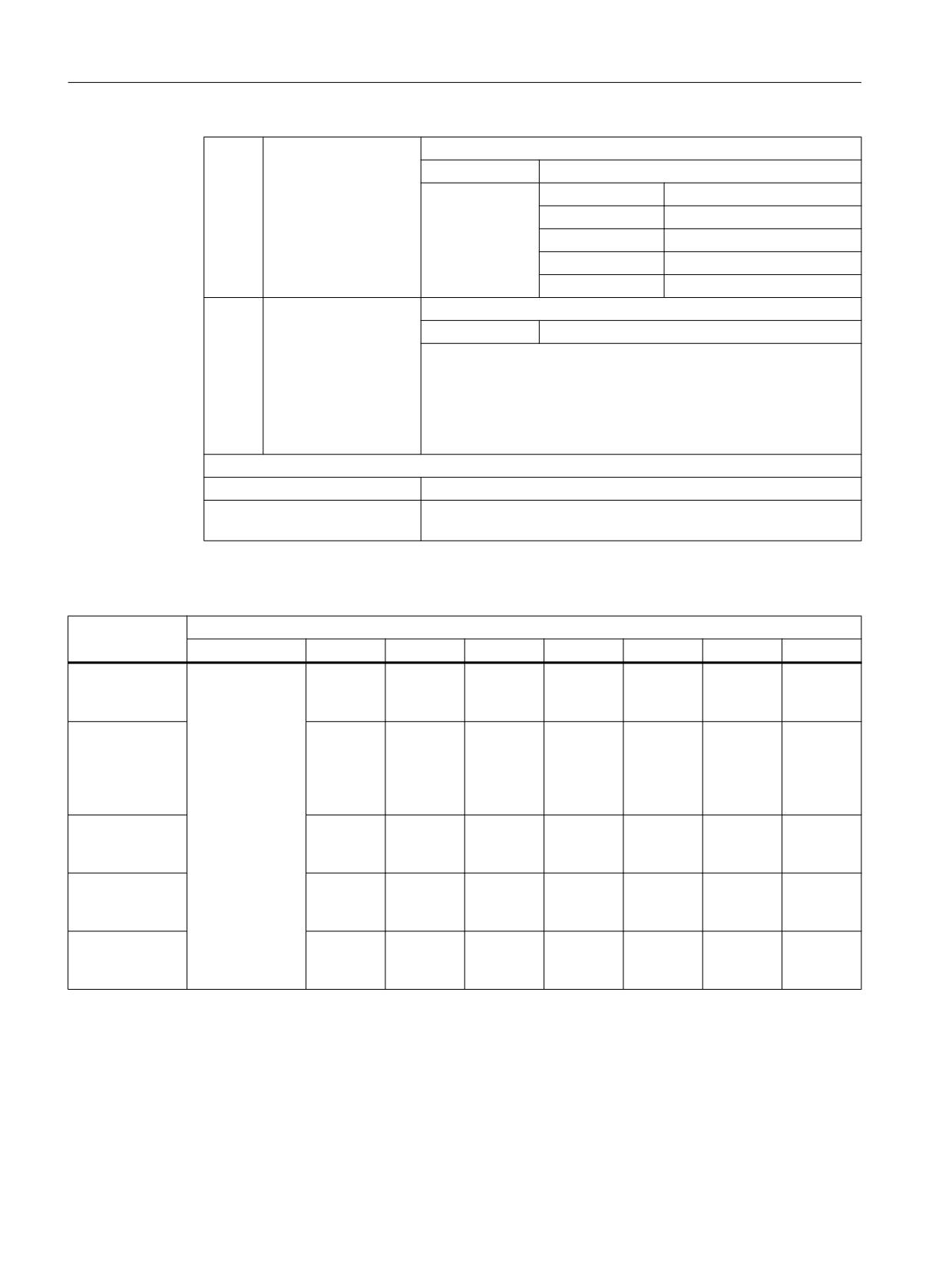
Table 18-1
Parameters for description of the blank shape
Blank shape
Parameter
<Par5>
<Par6>
<Par7>
<Par8>
<Par9>
<Par10>
<Par11>
<Par12>
Cylinder
Bit parameter
Refer-
Length Z1
Machin-
Outer di-
-
Rotation
-
ence point
ing dimen-
ameter d0
about ro-
Real value that
Z0
sion ZB
tary axis
is interpreted as
Pipe
bit-coded inte-
Refer-
Length Z1
Machin-
Outer di-
Wall thick-
Rotation
-
ger value. The
ence point
ing dimen-
ameter d0
ness
about ro-
bits define the
Z0
sion ZB
(inc) / in-
tary axis
meaning of the
ner diame-
following param-
ter d1 (abs)
eters (see "Bit
Centered cuboid
Refer-
Length Z1
Machin-
Width W
Length L
Rotation
-
parameters" ta-
ence point
ing dimen-
about ro-
ble).
Z0
sion ZB
tary axis
Cuboid
Refer-
Length Z1
Machin-
X0
Y0
X1
Y1
ence point
ing dimen-
Z0
sion ZB
Polygon with n
Refer-
Length Z1
Machin-
Number
Width
Rotation
-
edges
ence point
ing dimen-
of corners
across
about ro-
Z0
sion ZB
flats
tary axis
Job Planning
668
Programming Manual, 12/2018, A5E40869460B AB
Additional functions
18.12 Define blank (WORKPIECE)
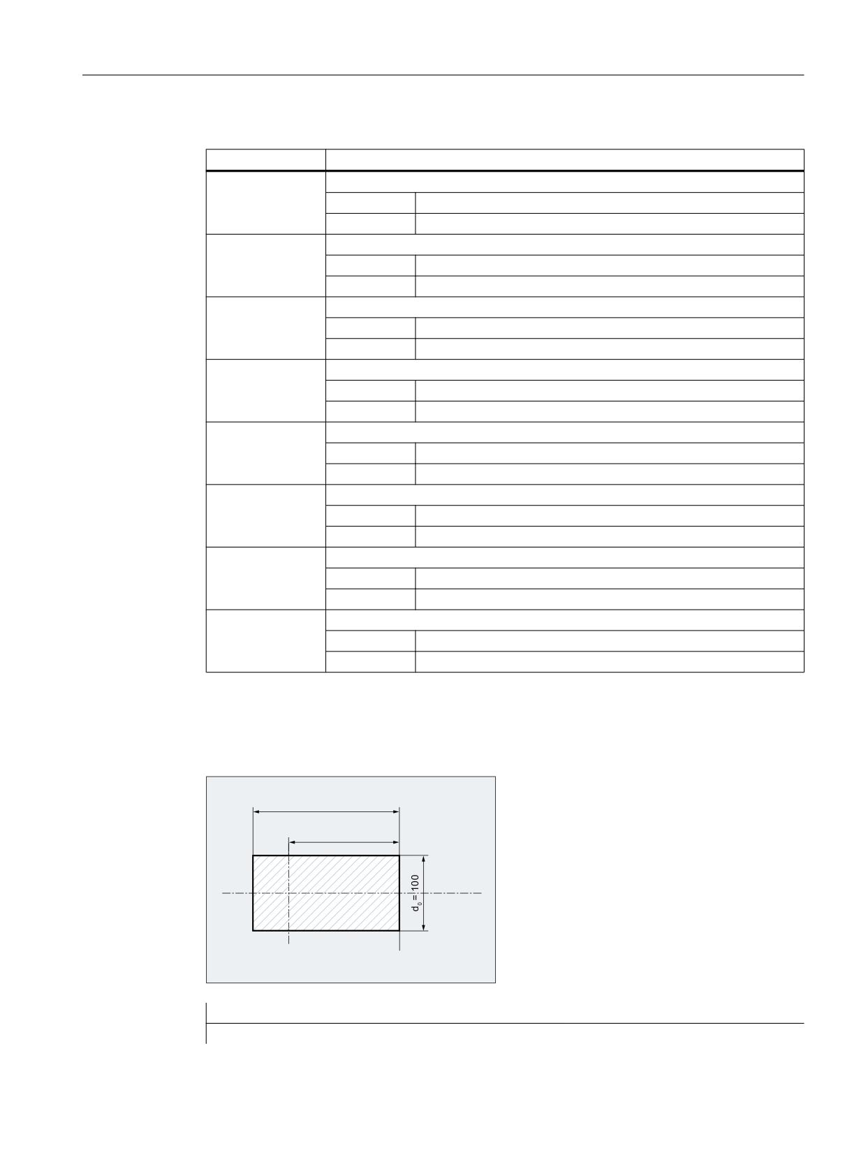
Table 18-2
Bit parameter
Bit
Meaning
4 (0x0010)
Cuboid: X1
= 0
inc
= 1
abs
5 (0x0020)
Cuboid: Y1
= 0
inc
= 1
abs
6 (0x0040)
Length Z1 (final dimension)
= 0
inc
= 1
abs
Bit 7 (0x0080)
Machining dimension ZB
= 0
inc
= 1
abs
Bit 8 (0x0100)
Pipe: Wall thickness / inner diameter
= 0
inc
= 1
abs
9 (0x0200)
Polygon with n edges
= 0
Width across flats
= 1
Edge length
12 (0x1000)
Clamping for turning machines
= 0
Main spindle
= 1
Counterspindle
13 (0x2000)
Counterspindle
= 0
with mirroring
= 1
without mirroring
Examples
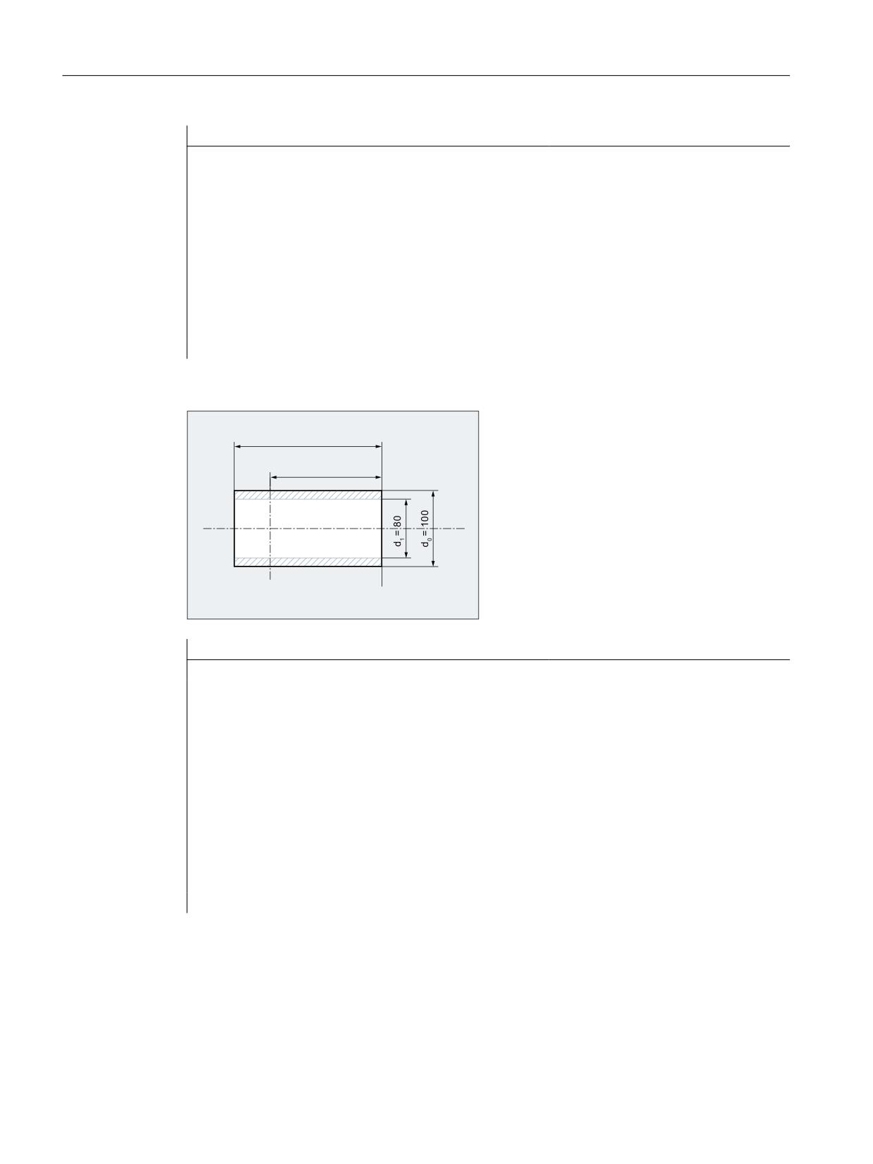
Example 1: Cylinder-shaped blank on a turning machine
=
=%
=
Program code
Comment
Job Planning
Programming Manual, 12/2018, A5E40869460B AB
669
Additional functions
18.12 Define blank (WORKPIECE)
Program code
Comment
WORKPIECE(,,,"CYLINDER",0,0,-200,-150,100)
; Blank definition:
; Blank shape: Cylinder
; Bit parameter=0(no bit set) →
Values for length and machining
dimension are incremental, blank
on main spindle
; Reference point(Z0)=0
; Length(Z1)=-200
; Machining dimension(ZB)=-150
; Outer diameter(d0)=100
Example 2: Pipe-shaped blank on a turning machine
=
=%
=
Program code
Comment
WORKPIECE(,,,"PIPE",256,0,-200,-150,100,80)
; Blank definition:
; Blank shape: Pipe
; Bit parameter=256(Bit8=1) → In-
ner diameter is absolute; length
and machining dimension are in-
cremental, blank on main spindle
; Reference point(Z0)=0
; Length(Z1)=-200
; Machining dimension(ZB)=-150
; Outer diameter(d0)=100
; Inner diameter(d1)=80
Job Planning
670
Programming Manual, 12/2018, A5E40869460B AB

Additional functions
18.13 Switch language mode (G290, G291)
18.13
Switch language mode (G290, G291)
The controller gives you the capability of reading in part programs from external CNC systems
and processing them. The prerequisite is that the corresponding NC language mode (ISO
dialect) has been defined during commissioning.
Reference:
Function Manual ISO Dialects
The ISO dialect mode can be activated separately for each channel. For example, channel 1
can run in ISO dialect mode while channel 2 is active in SINUMERIK mode.
The switchover between SINUMERIK mode and ISO dialect mode is done in the NC program
via the commands of the G-group 47. The active tool, tool compensation and work offsets are
not influenced by the switchover.
Syntax
G291
G290
Meaning
G290:
Activate SINUMERIK language mode
Alone in the block:
Yes
Effective:
Modal
G291:
Activate ISO language mode
Alone in the block:
Yes
Effective:
Modal
Conditions
SINUMERIK mode
● The default of the G commands can be defined for each channel via machine data.
● No language commands from the ISO dialects can be programmed in SINUMERIK mode.
ISO dialect mode
● The ISO dialect mode can be set with machine data as the basic setting of the control
system. In ISO dialect mode, the control system then reboots by default.
● Only G commands from the ISO dialect can be programmed. The programming of
SINUMERIK G functions is not possible in ISO dialect mode.
● ISO dialect and SINUMERIK language cannot be mixed in the same NC block.
● G commands cannot be used to switch between ISO dialect M (milling) and ISO dialect T
(turning).
Job Planning
Programming Manual, 12/2018, A5E40869460B AB
671
Additional functions
18.13 Switch language mode (G290, G291)
● Subprograms that are programmed in SINUMERIK mode can be called.
● If SINUMERIK functions are to be used, a switchover to SINUMERIK mode must first be
made (see example).
Example
Compression of linear blocks in the ISO dialect mode
Program code
Comment
N5 G290
; Activate SINUMERIK language mode.
N10 COMPON
; COMPON is a command in the Siemens lan-
guage and activates a compressor function
that replaces the successive linear
blocks with polynomial blocks with path
lengths that are as long as possible.
N15 G291
; Activate ISO language mode.
N20 G01 X100 Y100 F1000
; Since COMPON has been activated in SIN-
UMERIK mode, even linear blocks in the
ISO dialect mode can be compressed with
this function.
Job Planning
672
Programming Manual, 12/2018, A5E40869460B AB

Additional functions
18.14 Activate/deactivate load adjustment (CADAPTON, CADAPTOF)
18.14
Activate/deactivate load adjustment (CADAPTON, CADAPTOF)
Note
To use CADAPTON() and CADAPTOF(), a license is required for the following option:
● "Intelligent load adjustment" (Article number: 6FC5800-0AS11-0YB0)
Using the predefined CADAPTON() and CADAPTOF() procedures, predefined adaptation for
load-dependent adaptation of dynamic response and/or control parameters can be activated,
updated and deactivated from the part program. They are used in CYCLE782 (Page 763).
Syntax
CADAPTON(<Result>,<Axis>,<InVar>[,<InValue>])
CADAPTOF(<Result>,<Axis>,<InVar>)
Meaning
CADAPTON():
Activates adaptation relationship
CADAPTOF():
Deactivates adaptation relationship
Note:
Ignore active adaptation relationship (MD16501 = 1) CADAPTOF(), a previously pro-
grammed input value (<InVal>) remains active.
<Result>:
Result variable: Return value for the status (called by reference parameter)
Data type:
INT
Value:
0
No error
1
No valid adaptation table parameterized
2
<Axis> parameter invalid
3
<InVar> parameter invalid
4
Reserved
5
<InVal> parameter invalid
<Axis>:
Machine axis name of the input axis of the adaptation relationship
Data type:
AXIS
Range of
Machine axis names defined in the channel
values:
Note:
Using this parameter, those adaptations are addressed, which, in MD16504
$MN_CADAPT_INPUT_AX, entered a value corresponding to parameter <Axis>.
The other <InVar> and <InVal> parameters are assigned to this axis.
Job Planning
Programming Manual, 12/2018, A5E40869460B AB
673

Additional functions
18.14 Activate/deactivate load adjustment (CADAPTON, CADAPTOF)
<InVar>:
Input variable of the adaptation relationship
Data type:
INT
Value:
1
The axis moment of inertia is the input variable for the adaptation
2
Reserved
<InVal>:
Input value of the adaptation relationship (option)
Data type:
REAL
Value:
> 0
Actual moment of inertia
= 0
Load/loading is not defined or is not known. In this particular case,
the assigned adaptations supply substitute value 1.0 as output
variable.
< 0
The call is exited with <Status> = 5 (parameter <InVal> invalid).
The last input value activated remains active.
Note:
If an input value is not programmed, the last programmed value or the default value
(= 0) after the control system has run up is active.
Example
Program code
Comment
DEF INT RESULT
; Definition of result variables
CADAPTON(RESULT,MX1,1,1.23)
; Activate adaptation with input value
IF RESULT <> 0
; Evaluate the result variables (this is
required after each CADAPTON/CADAPTOF in-
struction)
MSG("CADAPT-RESULT=" << RESULT)
STOPRE
SETAL(61000)
ENDIF
CADAPTON(RESULT,MX1,1,2.34)
; Supply adaptation with new input value
; Evaluate result variables
CADAPTOF(RESULT,MX1,1)
; Deactivate adaptation
; Evaluate result variables
Further information
Link axes
The function cannot be applied to link axes (NCU-Link function). In this case, the result variable
would supply return value 2 ("Parameter <Axis> invalid").
Job Planning
674
Programming Manual, 12/2018, A5E40869460B AB
Additional functions
18.14 Activate/deactivate load adjustment (CADAPTON, CADAPTOF)
Block search
● Block search without calculation
CADAPTON/CADAPTOF instructions that are programmed between the beginning of the
program and target block are ignored. Users must select the search target so that the
adaptations relevant for the machining section are selected.
● Block search with calculation at the contour or at block end point
The activation and/or deactivation commands - as well as possible programmed input
values - are collected, and the actual status at the end of the search is output with the
search action blocks.
● Block search with calculation in Program test (SERUPRO) mode
When SERUPRO is deactivated, the status of the adaptations achieved using the
CADAPTON/CADAPTOF instructions is transitioned into real operation.
Job Planning
Programming Manual, 12/2018, A5E40869460B AB
675
Additional functions
18.14 Activate/deactivate load adjustment (CADAPTON, CADAPTOF)
Job Planning
676
Programming Manual, 12/2018, A5E40869460B AB
User stock removal programs
19
19.1
Supporting functions for stock removal
Preprogrammed stock removal programs are provided for stock removal. Beyond this, you
have the possibility of generating your own stock removal programs using the following listed
functions:
● Generate contour table (CONTPRON)
● Generate coded contour table (CONTDCON)
● Deactivate contour preparation (EXECUTE)
● Determine point of intersection between two contour elements (INTERSEC)
(Only for tables that were generated using CONTPRON)
● Execute contour elements of a table block-by-block (EXECTAB)
(Only for tables that were generated using CONTPRON)
● Calculate circle data (CALCDAT)
Note
You can use these functions universally, not just for stock removal.
Requirements
The following must be done before calling the CONTPRON or CONTDCON functions:
● A starting point that permits collision-free machining must be approached.
● The cutting radius compensation must be deactivated with G40.
Job Planning
Programming Manual, 12/2018, A5E40869460B AB
677

User stock removal programs
19.2 Generate contour table (CONTPRON)
19.2
Generate contour table (CONTPRON)
CONTPRON switches on the contour preparation. The NC blocks that are subsequently called
are not executed, but are split-up into individual movements and stored in the contour table.
Each contour element corresponds to one row in the two-dimensional array of the contour
table. The number of relief cuts is returned.
Syntax
Activate contour preparation:
CONTPRON(<contour table>,<machining type>,<relief cuts>,
<machining direction>)
Deactivate contour preparation and return to the normal execution mode:
EXECUTE(<ERROR>)
See "Deactivate contour preparation (EXECUTE) (Page 693)"
Meaning
CONTPRON:
Predefined procedure to activate the contour preparation to
generate a contour table
<contour table>:
Name of contour table
<machining type>:
Parameter for the machining type
Type:
CHAR
Value:
"G":
Longitudinal turning: Internal machin-
ing
"L":
Longitudinal turning: External machin-
ing
"N":
Face turning: Internal machining
"P":
Face turning: External machining
<relief cuts>:
Result variable for the number of relief cut elements that
occur
Type:
INT
<machining direction>:
Parameters for the machining direction
Type:
INT
Value:
0
Contour preparation, forward (default val-
ue)
1
Contour preparation in both directions
Example 1
Generating a contour table with:
● Name "KTAB"
● Max. 30 contour elements (circles, straight lines)
● One variable for the number of relief cut elements that occur
● One variable for error messages
Job Planning
678
Programming Manual, 12/2018, A5E40869460B AB
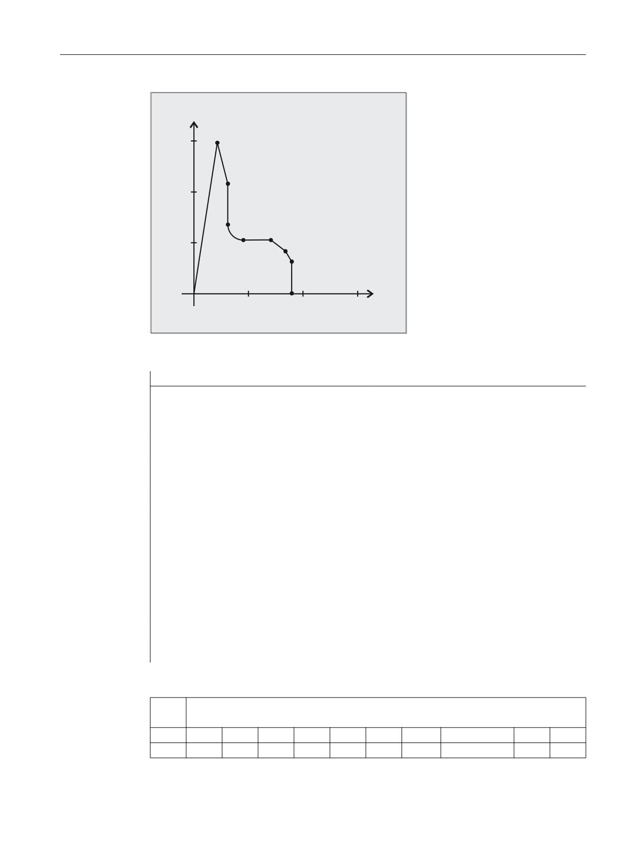
User stock removal programs
19.2 Generate contour table (CONTPRON)
;
=
NC program:
Program code
Comment
N10 DEF REAL KTAB[30,11]
; Contour table with the name KTAB and
max. 30 contour elements, parameter value
11 (number of table columns) is a fixed
quantity.
N20 DEF INT ANZHINT
; Variable for the number of relief cut
elements with the name ANZHINT.
N30 DEF INT ERROR
; Variable for error feedback signal
(0=no error, 1=error).
N40 G18
N50 CONTPRON(KTAB,"G",ANZHINT)
; Activate contour preparation.
N60 G1 X150 Z20
; N60 to N120: Contour description
N70 X110 Z30
N80 X50 RND=15
N90 Z70
N100 X40 Z85
N110 X30 Z90
N120 X0
N130 EXECUTE(ERROR)
; End filling the contour table, switch-
over to normal program mode.
N140 …
; Continue to process the table.
Contour table KTAB:
Index
Column
Line
(0)
(1)
(2)
(3)
(4)
(5)
(6)
(7)
(8)
(9)
(10)
7
7
11
0
0
20
150
0
82.40535663
0
0
Job Planning
Programming Manual, 12/2018, A5E40869460B AB
679

User stock removal programs
19.2 Generate contour table (CONTPRON)
0
2
11
20
150
30
110
-1111
104.0362435
0
0
1
3
11
30
110
30
65
0
90
0
0
2
4
13
30
65
45
50
0
180
45
65
3
5
11
45
50
70
50
0
0
0
0
4
6
11
70
50
85
40
0
146.3099325
0
0
5
7
11
85
40
90
30
0
116.5650512
0
0
6
0
11
90
30
90
0
0
90
0
0
0
0
0
0
0
0
0
0
0
0
0
0
0
0
0
0
0
0
0
0
0
0
Explanation of the column contents:
(0)
Pointer to next contour element (to the row number of that column)
(1)
Pointer to previous contour element
(2)
Coding the contour mode for motion
Possible values for X = abc
a = 102
G90 = 0
G91 = 1
b = 101
G70 = 0
G71 = 1
c = 100
G0 = 0
G1 = 1
G2 = 2
G3 = 3
(3), (4)
Starting point of contour elements
(3) = abscissa, (4) = ordinate of the current plane
(5), (6)
Starting point of the contour elements
(5) = abscissa, (6) = ordinate of the current plane
(7)
Max/min indicator: Identifies local maximum and minimum values on the contour
(8)
Maximum value between contour element and abscissa (for longitudinal machin-
ing) or ordinate (for face cutting). The angle depends on the type of machining
programmed.
(9), (10)
Center point coordinates of contour element, if it is a circle block.
(9) = abscissa, (10) = ordinate
Example 2
Generating a contour table with
● Name KTAB
● Max. 92 contour elements (circles, straight lines)
● Operating mode: Longitudinal turning, external machining
● Preparation, forward and backward
Job Planning
680
Programming Manual, 12/2018, A5E40869460B AB
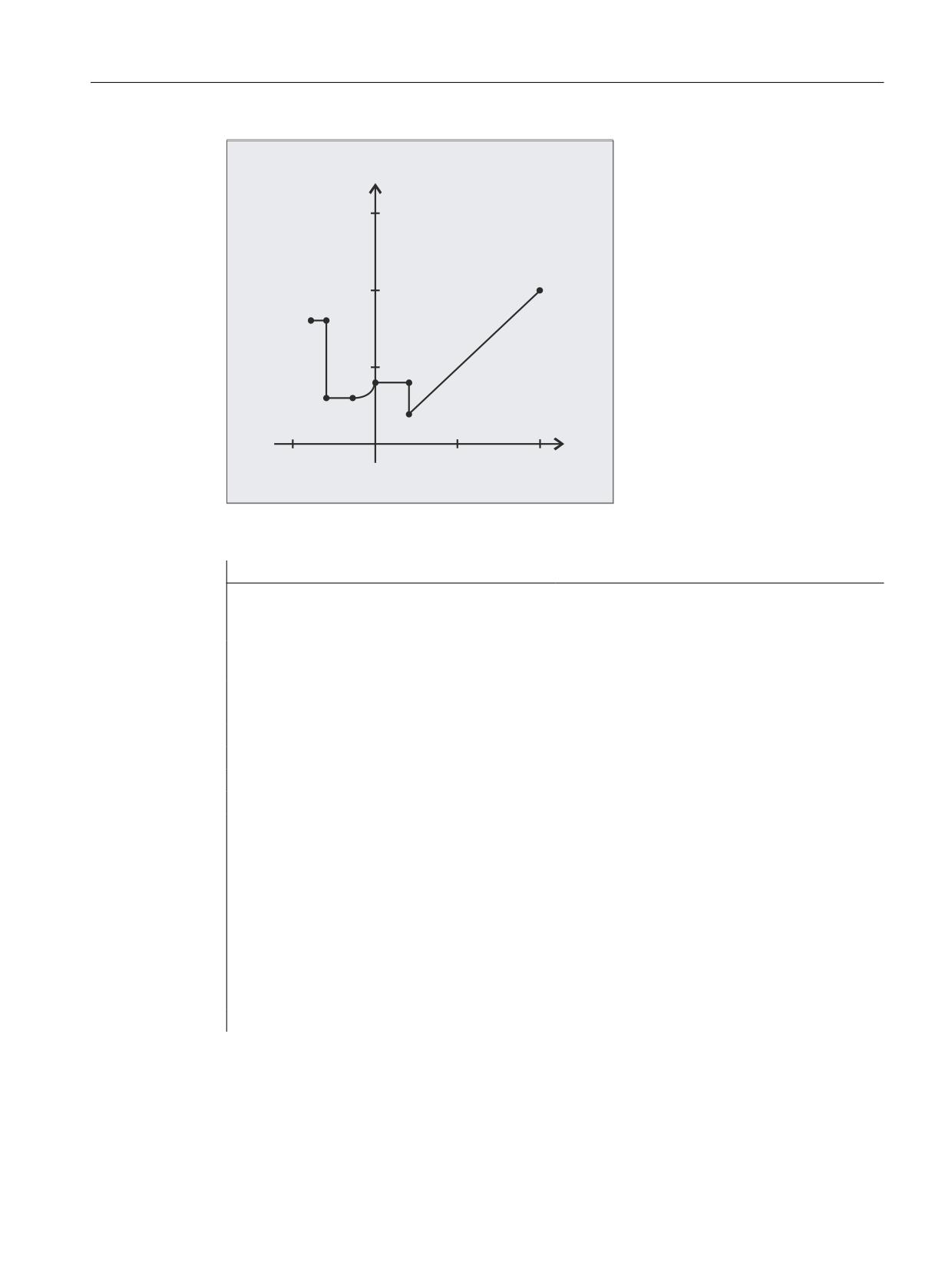
User stock removal programs
19.2 Generate contour table (CONTPRON)
;
=
NC program:
Program code
Comment
N10 DEF REAL KTAB[92,11]
; Contour table with name KTAB and max.
92 contour elements, parameter value 11
is a fixed quantity.
N20 DEF CHAR BT="L"
; Mode for CONTPRON: Longitudinal turn-
ing, external machining
N30 DEF INT HE=0
;Number of relief cut elements=0
N40 DEF INT MODE=1
; Preparation, forward and backward
N50 DEF INT ERR=0
; Error feedback signal
N100 G18 X100 Z100 F1000
N105 CONTPRON(KTAB,BT,HE,MODE)
; Activate contour preparation.
N110 G1 G90 Z20 X20
N120 X45
N130 Z0
N140 G2 Z-15 X30 K=AC(-15) I=AC(45)
N150 G1 Z-30
N160 X80
N170 Z-40
N180 EXECUTE(ERR)
; End filling the contour table, switch-
over to normal program mode.
Job Planning
Programming Manual, 12/2018, A5E40869460B AB
681
User stock removal programs
19.2 Generate contour table (CONTPRON)
Contour table KTAB:
After contour preparation is finished, the contour is available in both directions.
Index
Column
Line
(0)
(1)
(2)
(3)
(4)
(5)
(6)
(7)
(8)
(9)
(10)
0
61)
72)
11
100
100
20
20
0
45
0
0
1
03)
2
11
20
20
20
45
-3
90
0
0
2
1
3
11
20
45
0
45
0
0
0
0
3
2
4
12
0
45
-15
30
5
90
-15
45
4
3
5
11
-15
30
-30
30
0
0
0
0
5
4
7
11
-30
30
-30
45
-1111
90
0
0
6
7
04)
11
-30
80
-40
80
0
0
0
0
7
5
6
11
-30
45
-30
80
0
90
0
0
8
15)
26)
0
0
0
0
0
0
0
0
0
83
84
07)
11
20
45
20
80
0
90
0
0
84
90
83
11
20
20
20
45
-1111
90
0
0
85
08)
86
11
-40
80
-30
80
0
0
0
0
86
85
87
11
-30
80
-30
30
88
90
0
0
87
86
88
11
-30
30
-15
30
0
0
0
0
88
87
89
13
-15
30
0
45
-90
90
-15
45
89
88
90
11
0
45
20
45
0
0
0
0
90
89
84
11
20
45
20
20
84
90
0
0
91
839)
8510)
11
20
20
100
100
0
45
0
0
Explanation of column contents and comments for lines 0, 1, 6, 8, 83, 85 and 91
The explanations of the column contents given in example 1 apply.
Always in table line 0:
1) Predecessor: Line n contains the contour end (forward)
2) Successor: Line n is the contour table end (forward)
Once each within the contour elements forward:
3) Predecessor: Contour start (forward)
4) Successor: Contour end (forward)
Always in line contour table end (forward) +1:
5) Predecessor: Number of relief cuts (forward)
6) Successor: Number of relief cuts (backward)
Once each within the contour elements backward:
7) Successor: Contour end (backward)
8) Predecessor: Contour start (backward)
Always in last line of table:
9) Predecessor: Line n is the contour table start (backward)
Job Planning
682
Programming Manual, 12/2018, A5E40869460B AB
User stock removal programs
19.2 Generate contour table (CONTPRON)
10) Successor: Line n contains the contour start (backward)
Further information
Permitted traversing commands, coordinate system
The following G commands can be used for the contour programming:
● G group 1: G0, G1, G2, G3
In addition, the following are possible:
● Rounding and chamfer
● Circle programming using CIP and CT
The spline, polynomial and thread functions result in errors.
Changes to the coordinate system by activating a frame are not permissible between
CONTPRON and EXECUTE. The same applies for a change between G70 and G71 or G700 and
G710.
Replacing the geometry axes with GEOAX while preparing the contour table produces an alarm.
Relief cut elements
The contour description for the individual relief cut elements can be performed either in a
subprogram or in individual blocks.
Stock removal independent of the programmed contour direction
The contour preparation with CONTPRON was expanded so that after it has been called, the
contour table is available independent of the programmed direction.
Job Planning
Programming Manual, 12/2018, A5E40869460B AB
683

User stock removal programs
19.3 Generate coded contour table (CONTDCON)
19.3
Generate coded contour table (CONTDCON)
With the contour preparation activated with CONTDCON, the following NC blocks that are called
are saved in a coded form in a 6-column contour table to optimize memory use. Each contour
element corresponds to one row in the contour table. When familiar with the coding rules
specified below, e.g. you can combine DIN code programs for cycles from the table lines. The
data of the output point is saved in the table line with the number 0.
Syntax
Activate contour preparation:
CONTDCON(<contour table>,<machining direction>)
Deactivate contour preparation and return to the normal execution mode:
EXECUTE(<ERROR>)
See "Deactivate contour preparation (EXECUTE) (Page 693)"
Meaning
CONTDCON:
Predefined procedure to activate the contour preparation to
generate a coded contour table
<contour table>:
Name of the contour table
<machining direction>:
Parameter for machining direction
Type:
INT
Value:
0
Contour preparation according to the se-
quence of contour blocks (default value)
1
Not permissible
Note
The G commands permitted for CONTDCON in the program section to be included in the table
are more comprehensive than for CONTPRON. Further, feedrates and feedrate type are saved
for each contour section.
Example
Generating a contour table with:
● Name "KTAB"
● Contour elements (circles, straight lines)
● Operating mode: Turning
● Machining direction: Forward
Job Planning
684
Programming Manual, 12/2018, A5E40869460B AB
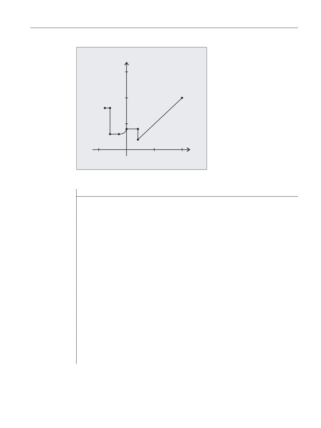
User stock removal programs
19.3 Generate coded contour table (CONTDCON)
;
=
NC program:
Program code
Comment
N10 DEF REAL KTAB[9,6]
;Contour table with name KTAB and 9
table cells. These allow 8 contour
sets. The parameter value 6 (column
number in table) is a fixed size.
N20 DEF INT MODE = 0
; Variable for the machining direc-
tion. Standard value 0: Only in the
programmed direction of the contour.
N30 DEF INT ERROR = 0
; Variable for the error feedback sig-
nal.
N100 G18 G64 G90 G94 G710
N101 G1 Z100 X100 F1000
N105 CONTDCON (KTAB, MODE)
; Contour preparation call (MODE can
be omitted).
N110 G1 Z20 X20 F200
; Contour description.
N120 G9 X45 F300
N130 Z0 F400
N140 G2 Z-15 X30 K=AC(-15) I=AC(45)F100
N150 G64 Z-30 F600
N160 X80 F700
N170 Z-40 F800
N180 EXECUTE(ERROR)
; End filling the contour table,
switchover to normal program mode.
Job Planning
Programming Manual, 12/2018, A5E40869460B AB
685

User stock removal programs
19.3 Generate coded contour table (CONTDCON)
Contour table KTAB:
Column index
0
1
2
3
4
5
Line index
Contour
End point
End point
Center point
Center point
Feedrate
mode
abscissa
ordinate
abscissa
ordinate
0
30
100
100
0
0
7
1
11031
20
20
0
0
200
2
111031
20
45
0
0
300
3
11031
0
45
0
0
400
4
11032
-15
30
-15
45
100
5
11031
-30
30
0
0
600
6
11031
-30
80
0
0
700
7
11031
-40
80
0
0
800
8
0
0
0
0
0
0
Explanation of the column contents:
Line 0 Coding for the starting point:
Column 0:
100 (ones digit): G0 = 0
101 (tens digit): G70 = 0, G71 = 1, G700 = 2, G710 = 3
Column 1:
Starting point abscissa
Column 2:
Starting point ordinate
Column 3-4:
0
Column 5:
Line index of last contour piece in the table
Lines 1-n: Entries for contour pieces
Column 0:
100 (ones digit): G0 = 0, G1 = 1, G2 = 2, G3 = 3
101 (tens digit): G70 = 0, G71 = 1, G700 = 2, G710 = 3
102 (hundreds digit): G90 = 0, G91 = 1
103 (thousands digit): G93 = 0, G94 = 1, G95 = 2, G96 = 3
104 (ten thousands digit): G60 = 0, G44 = 1, G641 = 2, G642 = 3
105 (hundred thousands digit): G9 = 1
Column 1:
End point abscissa
Column 2:
End point ordinate
Column 3:
Center point abscissa for circular interpolation
Column 4:
Center point ordinate for circular interpolation
Column 5:
Feedrate
Job Planning
686
Programming Manual, 12/2018, A5E40869460B AB
User stock removal programs
19.3 Generate coded contour table (CONTDCON)
Further information
Permitted traversing commands, coordinate system
The following G groups and G commands can be used for the contour programming:
G group 1:
G0, G1, G2, G3
G group 10:
G60, G64, G641, G642
G group 11:
G9
G group 13:
G70, G71, G700, G710
G group 14:
G90, G91
G group 15:
G93, G94, G95, G96, G961
In addition, the following are possible:
● Rounding and chamfer
● Circle programming using CIP and CT
The spline, polynomial and thread functions result in errors.
Changes to the coordinate system by activating a frame are not permissible between
CONTDCON and EXECUTE. The same applies for a change between G70 and G71 or G700 and
G710.
Replacing the geometry axes with GEOAX while preparing the contour table produces an alarm.
Machining direction
The contour table generated using CONTDCON is used for stock removal in the programmed
direction of the contour.
Job Planning
Programming Manual, 12/2018, A5E40869460B AB
687

User stock removal programs
19.4 Determine point of intersection between two contour elements (INTERSEC)
19.4
Determine point of intersection between two contour elements
(INTERSEC)
INTERSEC determines the point of intersection of two normalized contour elements from the
contour tables generated using CONTPRON.
Syntax
<Status>=INTERSEC(<contour table_1>[<contour element_1>],
<contour table_2>[<contour element_2>],<intersection
point>,<machining type>)
Meaning
INTERSEC:
Predefined function to determine the point of intersection between
two contour elements from the contour tables generated with
CONTPRON
<Status>:
Variable for the point of intersection status
Type:
BOOL
Value:
TRUE
Point of intersection found
FALSE
No intersection found
<contour table_1>:
Name of the first contour table
<contour element_1>:
Number of the contour element of the first contour table
<contour table_2>:
Names of the second contour table
<contour element_2>:
Number of the contour element of the second contour table
<point of intersection>:
Intersection coordinates in the active plane (G17 / G18 / G19)
Type:
REAL
<machining type>:
Parameter for the machining type
Type:
INT
Value:
0
Point of intersection calculation in the active
plane with parameter 2
(standard value)
1
Point of intersection calculation independent of
the transferred plane
Note
Please note that the variables must be defined before they are used.
The values defined with CONTPRON must be observed when transferring the contours:
Parameter
Meaning
2
Coding of contour mode for the movement
3
Contour start point abscissa
4
Contour start point ordinate
5
Contour end point abscissa
6
Contour end point ordinate
Job Planning
688
Programming Manual, 12/2018, A5E40869460B AB

User stock removal programs
19.4 Determine point of intersection between two contour elements (INTERSEC)
Parameter
Meaning
9
Center point coordinates for abscissa (only for circle contour)
10
Center point coordinates for ordinate (only for circle contour)
Example
Calculate the intersection of contour element 3 in table TABNAME1 and contour element 7 in
table TABNAME2. The intersection coordinates in the active plane are stored in the variables
ISCOORD (1st element = abscissa, 2nd element = ordinate). If no intersection exists, the
program jumps to NOCUT (no intersection found).
Program code
Comment
DEF REAL TABNAME1[12,11]
; Contour table 1
DEF REAL TABNAME2[10,11]
; Contour table 2
DEF REAL ISCOORD [2]
; Variable for the intersection coor-
dinates.
DEF BOOL ISPOINT
; Variable for the intersection sta-
tus.
DEF INT MODE
; Variable for the machining type.
…
MODE=1
; Calculation independent of the ac-
tive plane.
N10 ISPOINT=INTERSEC(TABNAME1[3],TABNAME2[7],
; Intersection of the contour ele-
ISCOORD,MODE)
ments call.
N20 IF ISPOINT==FALSE GOTOF NOCUT
; Jump to NOCUT.
…
Job Planning
Programming Manual, 12/2018, A5E40869460B AB
689
User stock removal programs
19.5 Execute the contour elements of a table block-by-block (EXECTAB)
19.5
Execute the contour elements of a table block-by-block (EXECTAB)
Using EXECTAB, you can execute the contour elements of a table - that were generated, e.g.
with CONTPRON - block-by-block.
Syntax
EXECTAB(<contour table>[<contour element>])
Meaning
EXECTAB:
Predefined procedure to execute a contour element
<contour table>:
Name of the contour table
<contour element>:
Number of the contour element
Example
Contour elements 0 to 2 in table KTAB should be executed block-by-block.
Program code
Comment
N10 EXECTAB(KTAB[0])
; Traverse element 0 of table KTAB.
N20 EXECTAB(KTAB[1])
; Traverse element 1 of table KTAB.
N30 EXECTAB(KTAB[2])
; Traverse element 2 of table KTAB.
Job Planning
690
Programming Manual, 12/2018, A5E40869460B AB

User stock removal programs
19.6 Calculate circle data (CALCDAT)
19.6
Calculate circle data (CALCDAT)
With CALCDAT, you can calculate the radius and the circle center point coordinates from the
three or four points known along the circle. The specified points must be different.
Where four points do not lie directly on the circle an average value is formed for the circle
center point and the radius.
Note
Calculation regulation for the averaging
The arc calculation is performed four times:
1. With circle points 1, 2, 3
2. With circle points 1, 2, 4
3. With circle points 1, 3, 4
4. With circle points 2, 3, 4
The values of the circle center point coordinates abscissa and ordinate are calculated by
adding the abscissa and ordinate values of the four arc calculations and dividing by four.
The radius is calculated by forming the root from the sum of the four radii from the arc
calculations and multiplying the result with 0.5.
Syntax
<Status>=CALCDAT(<circle points>[<number>,<type>],<number>,<result>)
Meaning
CALCDAT:
Predefined function to calculate the radius and center point coordinates
of a circle from three or four points
<Status>:
Variable for the circle calculation status
Type:
BOOL
Value:
TRUE
The specified points lie on a circle.
FALSE
The specified points do not lie on a circle.
<circle points>[]:
Variable to specify the circle points
using parameters
<number>:
Number of circle points (3 or 4)
<type>:
Type of coordinate data,
e.g. 2 for 2-point coordinates
<number>:
Parameter for the number of the points used for the calculation (3 or 4)
<result>[3]:
Variable for result:
Circle center point coordinates and radius
0
Circle center point coordinate: Abscissa value
1
Circle center point coordinate: Ordinate value
2
Radius
Job Planning
Programming Manual, 12/2018, A5E40869460B AB
691
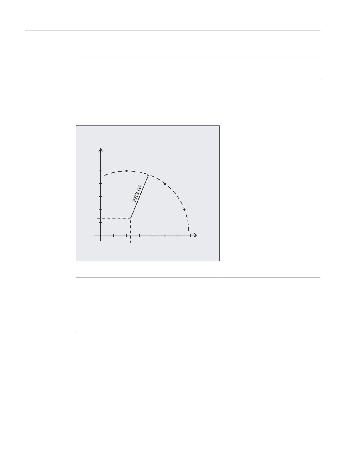
User stock removal programs
19.6 Calculate circle data (CALCDAT)
Note
Please note that the variables must be defined before they are used.
Example
Using three points it should be determined as to whether they are located on a circle segment.
<
(5* > @
;
(5* > @
Program code
Comment
N10 DEF REAL PT[3,2]=(20,50,50,40,65,20)
; Variable to specify the points
of a circle.
N20 DEF REAL RES[3]
; Variable for result.
N30 DEF BOOL STATUS
; Variable for status.
N40 STATUS=CALCDAT(PKT,3,ERG)
; Call of the determined circle
data.
N50 IF STATUS == FALSE GOTOF ERROR
; Jump to error.
Job Planning
692
Programming Manual, 12/2018, A5E40869460B AB

User stock removal programs
19.7 Deactivate contour preparation (EXECUTE)
19.7
Deactivate contour preparation (EXECUTE)
EXECUTE deactivates the contour preparation and at the same time the system returns to the
normal execution mode.
Syntax
EXECUTE(<ERROR>)
Meaning
EXECUTE:
Predefined procedure to terminate contour preparation
<ERROR>:
Variable for the error feedback signal
Type:
INT
The value of the variable indicates whether the contour was able to be prepared error-
free:
0
Error
1
No error
Example
Program code
N30 CONTPRON(...)
N40 G1 X... Z
N100 EXECUTE(...)
Job Planning
Programming Manual, 12/2018, A5E40869460B AB
693
User stock removal programs
19.7 Deactivate contour preparation (EXECUTE)
Job Planning
694
Programming Manual, 12/2018, A5E40869460B AB
Programming cycles externally
20
20.1
Technology cycles
20.1.1
Introduction
Contents
This section contains a description of the cycles for the turning, milling, and grinding
technologies.
Structure
The description of a cycle is structured as follows:
● Syntax
Cycle name and call sequence of the transfer parameters
● Parameters
Tables to explain the individual parameters
Parameter description
The following data is specified in the table for a parameter: Name, description, value range,
and dependencies on other parameters.
The column for reference to the parameter in the screen form is provided to more easily locate
values programmed on the control when externally generated cycle calls are recompiled.
"For interface only" parameters
Certain parameters are marked "for interface only" in the table. These are not relevant to
operation of the cycle. They are only needed in order to be able to recompile cycle calls
completely. If they are not programmed the cycle can still be recompiled; the fields are then
identified by color and must be completed in the mask.
"Reserved" parameters
Parameters that are described as "reserved" must be programmed with the value 0 or a comma
so that the assignment of the following call parameters matches the internal cycle parameters.
Exception: string parameters with the value "" or a comma.
Repeating cycles on a position pattern
Drilling and milling cycles can be repeated on the position pattern (modal calls). In such cases
MCALL should be written in the same line before the cycle, e.g. MCALL CYCLE83(...).
Job Planning
Programming Manual, 12/2018, A5E40869460B AB
695