SINUMERIK 840D sl/828D. Job Planning. Programming Manual (2010-2018) - page 7
Tool offsets
11.5 3D tool radius compensation
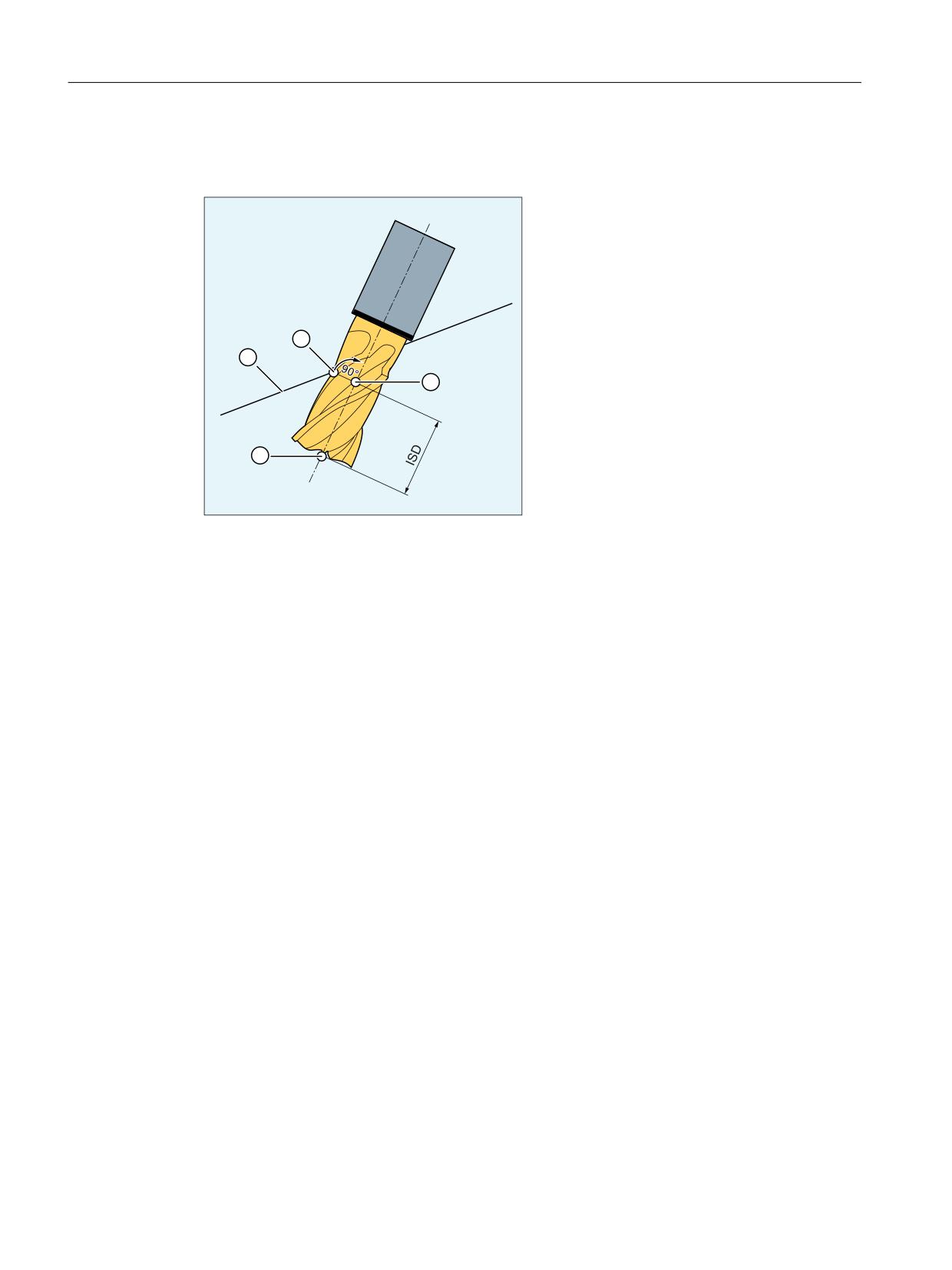
The position of the machining point on the peripheral surface of the tool is set with the insertion
depth.
① Programmed path
② Milling tool machining point
③ Milling tool reference point
④ Milling tool tip
ISD
Insertion depth (InSertion Depth)
Figure 11-2
Insertion depth
Tool radius compensation referred to a differential tool
3D TRC for circumferential milling referred to a differential tool is activated via the CUT3DCD
command. It should be applied if the programmed contour refers to the center-point path of a
standard tool, and a tool other than a differential tool is used for machining. When calculating
the 3D tool radius compensation, only the wear value of the radius of the active tool
($TC_DP15) and any programmed tool offsets OFFN and TOFFR are taken into account. The
basic radius ($TC_DP6) of the active tool is not taken into account.
Pocket milling with inclined side walls for circumferential milling with CUT3DC
In this 3D tool radius compensation, a deviation of the mill radius is compensated by infeed
toward the surface normals to be machined. The plane, in which the milling tool face is located,
remains unchanged if the insertion depth ISD has remained the same. For example, a milling
tool with a smaller radius than a standard tool would not reach the pocket base, which is also
the limitation surface. For automatic tool infeed, this limitation surface must be known to the
control, see Section "3D circumferential milling taking into account a limitation surface
(CUT3DCC, CUT3DCCD) (Page 426)".
Job Planning
420
Programming Manual, 12/2018, A5E40869460B AB

Tool offsets
11.5 3D tool radius compensation
Advanced Surface / Top Surface
Note
When applying tool radius compensation CUT3DCD in combination with the "Advanced
Surface" or "Top Surface" option (requiring a license), the setting recommendations regarding
"Advanced Surface" / "Top Surface" must be observed.
Special test programs are provided in the SIOS portal for checking the set data:
● Test programs for Advanced Surface (https://support.industry.siemens.com/cs/ww/en/view/
78956392)
● Test programs for Top Surface (https://support.industry.siemens.com/cs/ww/en/view/
109738423)
11.5.2
Selecting 3D tool radius compensation for the 3D face milling (CUT3DF,
CUT3DFS, CUT3DFF, CUT3DFD)
The 3D tool radius compensation (3D TRC) for the 3D face milling is selected with the modally
effective G command CUT3DF, CUT3DFS, CUT3DFF or CUT3DFD.
The actual activation is performed with G41 or G42
With 3D face milling, the surface normals of the plane to be machined must be defined in order
to calculate the tool radius compensation. This must be performed in the block with G41 or
G42 via the A4, B4, C4 and A5, B5, C5 addresses.
The tool radius compensation is deactivated with G40.
Syntax
G41/G42 ORIC/ORID CUT3DF/CUT3DFS/CUT3DFF/CUT3DFD X... Y... Z... A4=... B4=...
C4=... A5=... B5=... C5=
G40 X... Y... Z...
Meaning
CUT3DFS:
3D TRC for face milling with constant orientation. The tool
orientation is defined by G17 - G19 and is not influenced by
frames.
CUT3DFF:
3D TRC for face milling with constant orientation. The tool
orientation is the direction defined by G17 - G19 and, in some
case, rotated by a frame.
CUT3DF:
3D TRC for face milling with orientation change (only with
active 5-axes transformation)
Job Planning
Programming Manual, 12/2018, A5E40869460B AB
421

Tool offsets
11.5 3D tool radius compensation
CUT3DFD:
3D TRC for face milling with orientation change referred to a
differential tool (only with active 5-axis transformation)
The radius difference is specified by the tool parameter
$TC_DP15.
Note:
CUT3DFD is only possible in combination with "Smoothing
of surface normals in 3D face milling". This is activated by
calling the "Top Surface" function (requires as license) via
CYCLE832(...) (Page 778).
G41/G42 X... Y... Z... :
Activate tool offset
The behavior with G41 and with G42 is identical for 3D face
milling.
Note:
The activation must be performed in a linear block (G0/G1).
A4/5=... B4/5=... C4/5=...:
Definition of the surface normals of the plane to be machined
A4=... B4=... C4=...:
Definition at start of block
A5=... B5=... C5=...:
Definition at end of block
ORIC/ORID:
The behavior for orientation changes at outside corners is
specified via the G commands ORIC and ORID.
ORIC:
Orientation changes at outside corners are su-
perimposed on the circle block to be inserted.
ORID:
Orientation changes are performed before the
circle block.
G40 X... Y... Z... :
Deactivate tool radius compensation
Note:
The deactivation must be performed in a linear block (G0/G1)
with geometry axis movements.
Note
G41 or G42 can also be programmed in blocks without traversing movement in geometry axes
relevant for the compensation. In this case, the approach block is the first traversing block
following such a block.
A change of the 3D TRC variant with active tool radius compensation is ignored without alarm.
Examples
Example 1: 3D face milling with CUT3DF
Program code
Comment
N10
; Definition of tool D1:
N20 $TC_DP1[1,1]=121
; Tool type (toroidal miller)
N30 $TC_DP3[1,1]=20
; Length compensation
N40 $TC_DP6[1,1]=5
; Radius
N50 $TC_DP7[1,1]=3
; Rounding radius
N60
N70
Job Planning
422
Programming Manual, 12/2018, A5E40869460B AB
Tool offsets
11.5 3D tool radius compensation
Program code
Comment
N80 X0 Y0 Z0 A0 B0 C0 G17 T1 D1 F12000
; Selection of the tool.
N90 TRAORI(1)
; Select orientation transformation.
N100 B4=-1 C4=1
; Definition of the plane.
N110 G41 ORID CUT3DF G64 X10 Y0 Z0
; Activate tool offset.
N120 X30
N130 Y20 A4=1 C4=1
; Outside corner, new plane definition.
N140 B3=1 C3=5
; Change in orientation with ORID.
N150 B3=1 C3=1
; Change in orientation with ORID.
N160 X-10 A5=1 C5=2 ORIC
N170 A3=-2 C3=1
; Change in orientation with ORIC.
N180 A3=-1 C3=1
; Change in orientation with ORIC.
N190 Y-10 A4=-1 C4=3
; New plane definition.
N200 X-20 Y-20 Z10
; Inside corner with previous block.
N210 X-30 Y10 A4=1 C4=1
; Inside corner, new plane definition.
N220 A3=1 B3=0.5 C3=1.7
; Change in orientation with ORIC.
N230 X-20 Y30 A4=1 B4=-2 C4=3 ORID
N240 A3 = 0.5 B3=-0.5 C3=1
; Change in orientation.
N250 X0 Y30 C4=1
; Path movement, new plane,
; orientation with relative programming.
N260 BSPLINE X20 Z15
; Spline begin, relative programming of the orien-
tation
N270 X30 Y25 Z18
; remains active during spline.
N280 X40 Y20 Z13
N290 X45 Y0 PW=2 Z8
N300 Y-20
N310 G2 ORIMKS A30 B45 I-20 X25 Y-40 Z0
; Helix, orientation with axis programming.
N320 G1 X0 A3=-0.123 B3=0.456 C3=2.789 B4=-1 C4=5
; Path movement, orientation, non-constant plane.
B5=-1 C5=2
N330 X-20 G40
; Deactivation of the tool radius compensation.
N340 M30
Example 2: NC program (section) generated from a CAD system with CUT3DFD
Program code
Comment
N01 G710
N03 T="12"
N06 S5305 M03
N07 G642
; Approaching the starting position in the MCS taking the tool length into account.
G00 G90 X-250.62787 Y-38.37944 A=DC(253.12719)
B-12.49543
G00 G90 Z251.80052
; End of positioning in the MCS.
;
Job Planning
Programming Manual, 12/2018, A5E40869460B AB
423
Tool offsets
11.5 3D tool radius compensation
Program code
Comment
TRAORI(1)
; Select orientation transformation.
G500
D1
CYCLE832(0.01, _TOP_SURFACE_SMOOTH_ON + _ORI_FIN-
; Call CYCLE832 with:
ISH, 1)
; Contour tolerance = 0.01 mm,
; Processing type: Top Surface with smoothing,
; Finishing with input of an orientation toler-
ance,
; Orientation tolerance = 1 degree
CUT3DFD
N08 G90 G94
N09 G00 X-269.21195 Y128.32027 Z1.18577
; The blocks N09 to N10 are the fast portion of
A3=-.216361688 B3=.934284397 C3=-.283373051
the approach movement to the workpiece with con-
stant orientation.
N10 G00 X-251.90301 Y53.57752 Z23.85561
N11 G01 X-247.57578 Y34.89183 Z29.52308 F50000.00000
; In the blocks N11 to N21, the slow portion of
the approach movement is realized. The tool is
already close to the workpiece; furthermore, the
mold making settings (e.g. COMPSURF) from the CY-
CLE832 are now active (due to active G01). The
path of this so-called transient phase for the
mold-making behavior should be about 1000 times
the contour tolerance (10 mm in this example).
N12 X-247.69126 Y33.82182 Z24.78219 F1061.00000
N13 X-247.76560 Y33.13299 Z21.73022
N14 X-247.82755 Y32.55897 Z19.18691
N15 X-247.87918 Y32.08062 Z17.06748
N16 X-247.92220 Y31.68200 Z15.30129
N17 X-247.95805 Y31.34981 Z13.82947
A3=-.216361686 B3=.934284391 C3=-.283373071
N18 X-247.98792 Y31.07299 Z12.60295
A3=-.216360662 B3=.934280801 C3=-.283385691
N19 X-248.01282 Y30.84230 Z11.58085
A3=-.216336015 B3=.934194446 C3=-.283689030
N20 X-248.03357 Y30.65006 Z10.72910
A3=-.216233089 B3=.933833626 C3=-.284952647
N21 X-248.05086 Y30.48986 Z10.01931
A5=-.060687572 B5=.974940255 C5=-.214029243
A3=-.215712821 B3=.932005189 C3=-.291263295
N22 G41 X-248.06237 Y30.32400 Z9.36695
; From N22, the surface normal is completely de-
A5=-.060431854 B5=.973045457 C5=-.222554556
fined over the entire block for the first time
A3=-.214974689 B3=.929398552 C3=-.300007025
(i.e. surface normal at the end of the previous
F1061.03295
block N21 is present, thus the surface normal at
the beginning of the block N22 and the surface
normal at the end of the block N22). Thus the
prerequisite for switching on the tool offset
with G41/G42 is fulfilled.
Job Planning
424
Programming Manual, 12/2018, A5E40869460B AB
Tool offsets
11.5 3D tool radius compensation
Program code
Comment
N23 X-248.07130 Y30.15119 Z8.71082
A5=-.060165696 B5=.971048883 C5=-.231179920
A3=-.214177198 B3=.926684940 C3=-.308841625
N24 X-248.07829 Y29.97126 Z8.05094
A5=-.059884286 B5=.968941717 C5=-.239928784
A3=-.213318480 B3=.923853466 C3=-.317789237
N25 X-248.08317 Y29.78487 Z7.38844
A5=-.059584206 B5=.966718449 C5=-.248807482
A3=-.212397895 B3=.920898045 C3=-.326854594
N26 X-248.08578 Y29.59254 Z6.72679
A5=-.059263963 B5=.964380907 C5=-.257793037
A3=-.211418355 B3=.917822366 C3=-.336012474
Note
For 3D face milling with CUT3DFD, the definition of the surface normal is required for activating
the tool offset with G41/G42. Programming of G41/G42 without definition of the surface
normals leads to the output of an alarm.
Further information
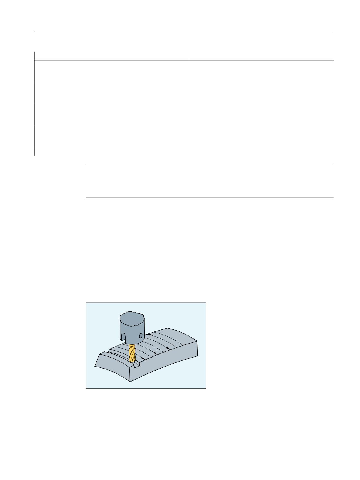
3D face milling
For this type of 3D milling, you require the line-by-line description of the 3D paths on the
workpiece surface. The tool shape and dimensions are taken into account in the calculations,
which are normally performed in CAM. The postprocessor writes to the part program - in
addition to NC blocks - the tool orientations (for active 5-axis transformation) and the G
command for the required 3D tool offset. This means that the machine operator has the
possibility of using tools that are slightly smaller - deviating from the tool used to calculate the
NC paths.
Figure 11-3
Face milling
Approach behavior
The approach behavior is always NORM for the 3D variant of the tool radius compensation.
Job Planning
Programming Manual, 12/2018, A5E40869460B AB
425
Tool offsets
11.5 3D tool radius compensation
Behavior at outside corners
Outside corners are treated as circles with radius 0 for face milling, whereby the circle plane
extends from the end tangent of the first block to the start tangent of the second block. In this
way, the orientation can be changed during block transition. A circle is therefore always
inserted as contour element at an outside corner. The intersection procedure is not available
with face milling.
Behavior for changes in orientation at outside corners
The ORIC and ORID G commands are used to determine whether changes in orientation
programmed between two blocks forming the corner are executed before the inserted circle
block (ORID) is processed or at the same time (ORIC).
Tool radius compensation referred to a differential tool
3D tool radius compensation referring to a differential tool is selected using the CUT3DFD
command. It should be applied if the programmed contour refers to the center-point path of a
standard tool, and a tool other than a differential tool is used for machining. When calculating
the 3D tool radius compensation, only the wear value of the radius of the active tool
($TC_DP15) and any programmed tool offsets OFFN and TOFFR are taken into account. The
basic radius ($TC_DP6) of the active tool is not taken into account.
3D face milling with CUT3DFD is only possible in combination with "Smoothing of surface
normals in 3D face milling". This is activated by calling the "Top Surface" function (requires as
license) via CYCLE832(...) (Page 778). Activation must take place before the tool offset is
activated with G41/G42; not directly before tool intervention, but rather one path length before
that, which corresponds to approx. 1000 times the contour tolerance (e.g. 1000 x 0.01 mm =
10 mm). Deactivation must be executed in reverse order: First switch off the tool offset with
G40, then deactivate with e.g. CUT2D (or similar) after a path length which corresponds with
approximately 1000 time the contour tolerance.
In order to be able to use the "Smoothing of surface normals in 3D face milling", the
"Interpolation of surface normals via polynomials" function must also be enabled:
MD28291 $MC_MM_SMOOTH_SURFACE_NORMALS = TRUE
Note
For 3D face milling with CUT3DFD in combination with "Top Surface", the setting
recommendations regarding "Top Surface" must be observed.
Special test programs are provided (https://support.industry.siemens.com/cs/ww/en/view/
109738423) in the SIOS portal for checking the set data.
11.5.3
3D circumferential milling taking into account a limitation surface (CUT3DCC,
CUT3DCCD)
In 3D circumferential milling with a continuous or constant change in tool orientation, the tool
center-point path is frequently programmed for a defined standard tool. Because in practice
suitable standard tools are often not available, a tool that does not deviate too much from a
standard tool (≤ 5%) can be used.
Job Planning
426
Programming Manual, 12/2018, A5E40869460B AB

Tool offsets
11.5 3D tool radius compensation
CUT3DCCD takes account of a limitation surface for a real differential tool that the programmed
standard tool would define. The NC program defines the center-point path of a standard tool.
CUT3DCC with the use of cylindrical tools takes account of a limitation surface that the
programmed standard tool would have reached. The NC program defines the contour on the
machining surface.
The surface normal vector of the limitation surface is specified with A4, B4, C4 and A5, B5,
C5 for 3D face milling.
Syntax
G41/G42 CUT3DCCD/CUT3DCC CDOF2 X... Y... Z... A4=... B4=... C4=... A5=... B5=...
C5=
G40 X... Y... Z...
Meaning
CUT3DCCD:
3D TRC for the circumferential milling taking into account a limitation
surface with a differential tool on the tool center-point path: Infeed
to the limitation surface
CUT3DCC:
3D TRC for the circumferential milling taking into account a limitation
surface with 3D radius compensation: Contour on the machining
surface
G41/G42 X... Y... Z... :
Activate tool radius compensation
G41:
Tool radius compensation left of the contour
G42:
Tool radius compensation right of the contour
Note:
The activation must be performed in a linear block (G0/G1).
CDOF2:
Deactivate collision detection for 3D circumferential milling
A4/5=... B4/5=...
Definition of the surface normals of the limitation surface
C4/5=...:
A4=... B4=... C4=...:
Definition at start of block
A5=... B5=... C5=...:
Definition at end of block
G40 X... Y... Z... :
Deactivate tool radius compensation
Note:
The deactivation must be performed in a linear block (G0/G1) with
geometry axis movements.
Note
The G commands for selecting the 3D TRC are evaluated in the approach block, i.e. typically
in the block that contains G41 or G42.
G41 or G42 can also be programmed in blocks without traversing movement in geometry axes
relevant for the compensation. In this case, the approach block is the first traversing block
following such a block.
A change of the 3D TRC variant with active tool radius compensation is ignored without alarm.
Job Planning
Programming Manual, 12/2018, A5E40869460B AB
427
Tool offsets
11.5 3D tool radius compensation
Example
Program code
Comment
N10 $TC_DP1[1,1]=120
; Cylindrical milling tool
N20 $TC_DP6[1,1]=10
N30 $TC_DP15[1,1]=-3
; Processing with cylindrical milling tool and CUT3DCCD
N110 TRAORI
; Activation of the transformation.
N120 A4=0 B4=0 C4=1
; Definition of the surface normal of the
limitation surface at the start of the
block.
N130 X0 Y0 Z0 A0 C0 T1 D1 F20000
N140 X10 Y0 Z0 G41 CUT3DCCD CDOF2 G64
; Activate 3D circumferential milling,
taking into account the limitation sur-
face + switching off collision detection.
N150 X20
N160 X30 A45
; Obtuse angle ==> no infeed
N170 X40 A-45
; Acute angle ==> infeed
N180 X55
N190 Y10 Z10
; Movement in the tool direction.
N200 Y20
N210 C45
; Pure change in orientation.
N220 Y30 C90
N230 A5=-1 B5=0 C5=2 Y40
; Change of the surface.
N240 Y50 G40
; Deactivation of the tool radius compen-
sation.
Further information
Tool type
The tool type (tool parameter $TC_DP1) is evaluated. Only milling tools with cylindrical shank
(cylinder or end mill, toroidal miller and, in the limit case, cylindrical die mill) are permitted. This
corresponds to the tool types 1 - 399, with the exception of the numbers 111 and 155 to 157.
Standard tools with corner rounding
Corner rounding with a standard tool is defined by the tool parameter $TC_DP7. Tool
parameter $TC_DP16 describes the deviation of the corner rounding of the real tool compared
with the standard tool.
Job Planning
428
Programming Manual, 12/2018, A5E40869460B AB
Tool offsets
11.5 3D tool radius compensation
Example: Toroidal miller with reduced radius compared to the standard tool
Tool type
Shaft radius (R)
Corner radius (r)
Standard tool with corner rounding
R = $TC_DP6
r = $TC_DP7
Real tool with corner rounding
R' = $TC_DP6 + $TC_DP15 +
r' = $TC_DP7 + $TC_DP16
OFFN
Tool types 121 and 131 toroidal
miller
(end mill with corner rounding)
In this example, both $TC_DP15 + OFFN and $TC_DP16 are negative.
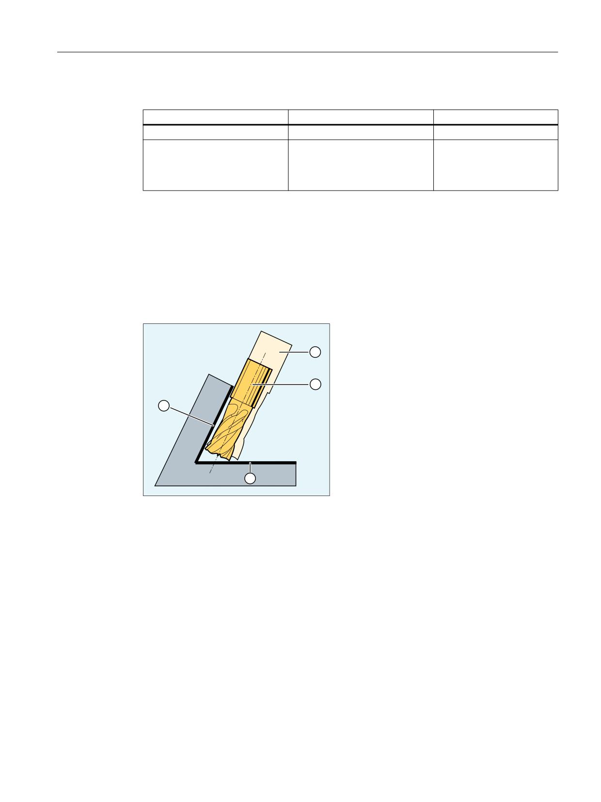
3D TRC with CUT3DCCD: Tool center-point path with infeed up to the limitation surface
If a tool with a smaller radius than the appropriate standard tool is used, machining is continued
using a milling tool, which is fed in in the longitudinal direction until it reaches the bottom (base)
of the pocket. The tool removes as much material from the corner formed by the machining
surface and limitation surface. This involves a machining type combining circumferential and
face milling. Analogous to a tool with reduced radius, for a tool with increased radius, the infeed
is in the opposite direction.
① Standard tool
② Tool with smaller radius infeed up to the limitation surface
③ Limitation surface
④ Machining surface
Contrary to all other tool offsets of G group 22, tool parameter $TC_DP6 specified for
CUT3DCCD has no relevance for the tool radius and does not influence the resulting
compensation. The compensation offset results from the sum of the wear value of the tool
radius (tool parameter $TC_DP15) and a tool offset OFFN programmed to calculate the
perpendicular offset to the limitation surface.
The generated part program does not specify whether the surface to be machined is to the
right or left of the path. It is therefore assumed that the radius is a positive value and the wear
value of the original tool is a negative value. A negative wear value always describes a tool
with a reduced diameter.
Job Planning
Programming Manual, 12/2018, A5E40869460B AB
429
Tool offsets
11.5 3D tool radius compensation
Using cylindrical tools
When cylindrical tools are used, infeed is only necessary if the machining surface and the
surface of limitation form an acute angle (less than 90 degrees). If a toroidal miller (end mill
with corner rounding) is used, tool infeed in the longitudinal direction is required for both acute
and obtuse angles.
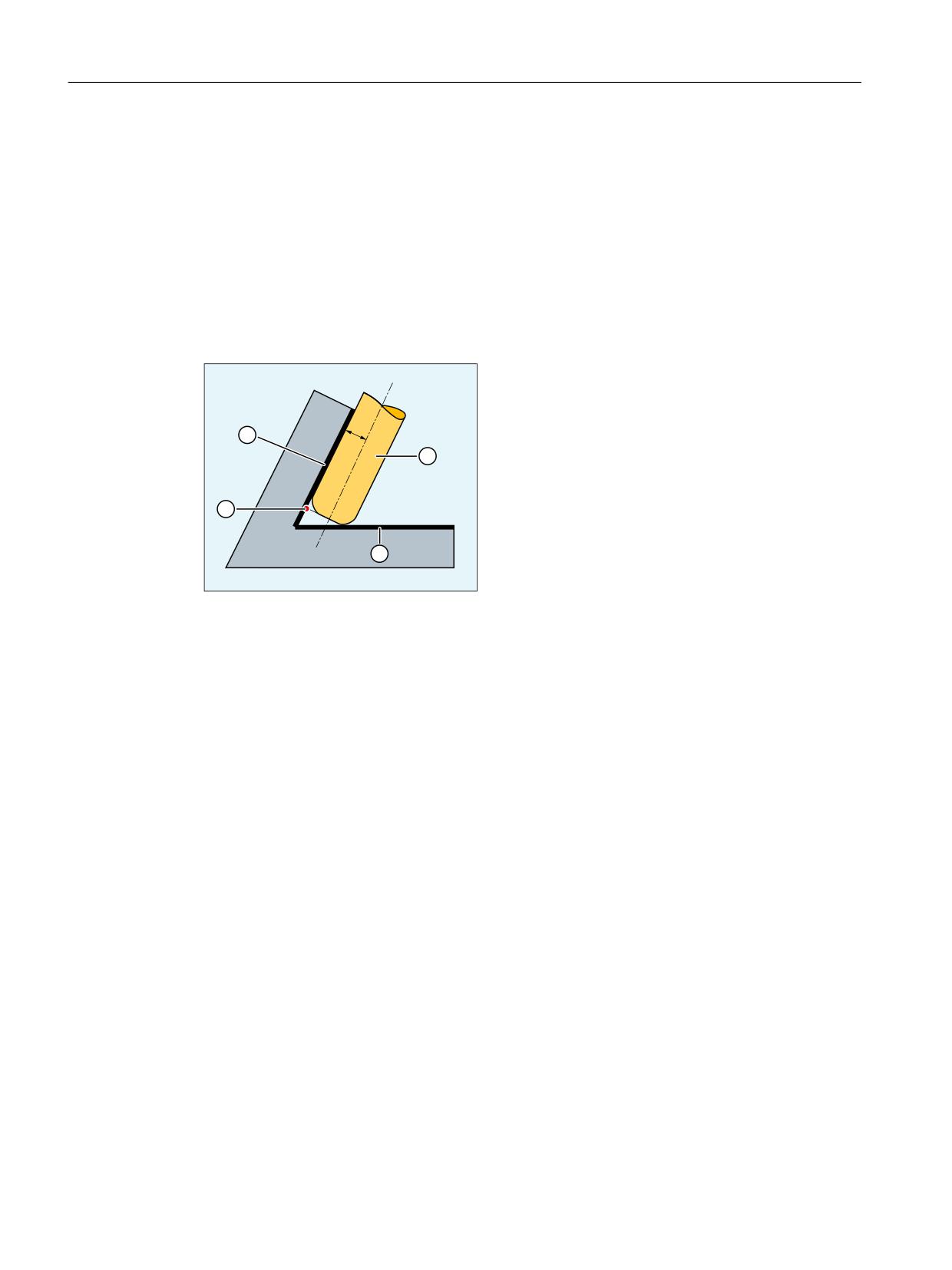
3D TRC with CUT3DCC: Contour on the machining surface
If CUT3DCC is active with a toroidal miller, the programmed path refers to a fictitious cylindrical
milling tool having the same diameter. The resulting path reference point is shown in the
following diagram for a toroidal miller.
5
① Toroidal miller
② Limitation surface
③ Path reference point
④ Machining surface
R
Shaft radius (tool radius)
The angle between the machining and limitation surfaces may change from an acute to an
obtuse angle and vice versa even within the same block.
The tool actually being used may either be larger or smaller than the standard tool. However,
the resulting corner radius must not be negative and the sign of the resulting tool radius must
be kept.
For CUT3DCC, the NC part program refers to the contour on the machining surface. As for
conventional tool radius compensation, the total tool radius is used that comprises the following
components:
● Tool radius (tool parameter $TC_DP6)
● Wear value (tool parameter $TC_DP15)
● A tool offset OFFN programmed to calculate the perpendicular offset to the limitation surface
The position of the limitation surface is defined from the following difference:
Dimensions of the standard tool - tool radius (tool parameter $TC_DP6)
Job Planning
430
Programming Manual, 12/2018, A5E40869460B AB
Tool offsets
11.5 3D tool radius compensation
Advanced Surface / Top Surface
Note
When applying tool radius compensation CUT3DCC / CUT3DCCD in combination with the
"Advanced Surface" or "Top Surface" function (requiring a license), the setting
recommendations regarding "Advanced Surface" / "Top Surface" must be observed.
Special test programs are provided in the SIOS portal for checking the set data:
● Test programs for Advanced Surface (https://support.industry.siemens.com/cs/ww/en/view/
78956392)
● Test programs for Top Surface (https://support.industry.siemens.com/cs/ww/en/view/
109738423)
Job Planning
Programming Manual, 12/2018, A5E40869460B AB
431
Tool offsets
11.6 Tool orientation (ORIC, ORID, OSOF, OSC, OSS, OSSE, ORIS, OSD, OST)
11.6
Tool orientation (ORIC, ORID, OSOF, OSC, OSS, OSSE, ORIS,
OSD, OST)
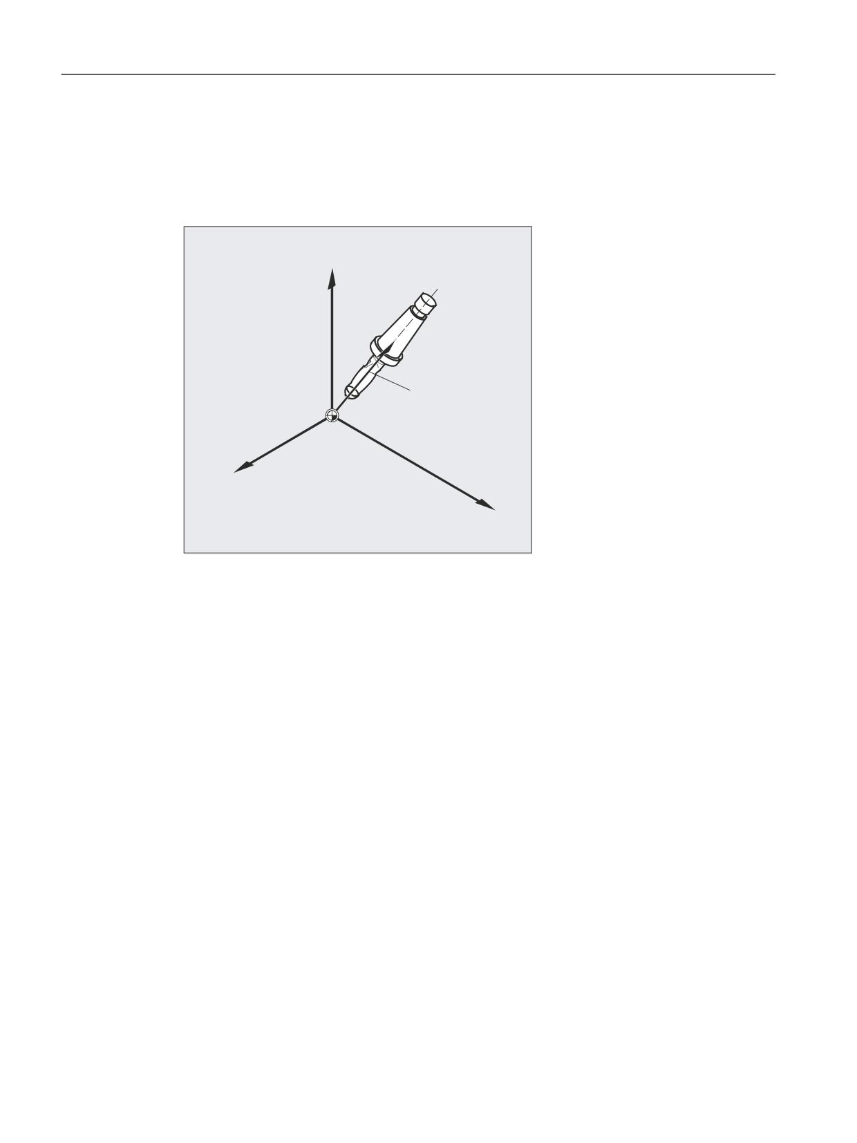
The term tool orientation describes the geometric alignment of the tool in space. The tool
orientation on a 5-axis machine tool can be set by means of program commands.
=
'LUHFWLRQ YHFWRU
;
<
Orientation rounding movements activated with OSD and OST are formed differently depending
on the type of interpolation for tool orientation.
If vector interpolation is active, the smoothed orientation characteristic is also interpolated
using vector interpolation. On the other hand, if rotary axis interpolation is active, the orientation
is smoothed directly using rotary axis movements.
Programming
Programming a orientation change:
A change in tool orientation can be programmed by:
● Direct programming of rotary axes A, B, C (rotary axis interpolation)
● Euler or RPY angle
● Direction vector (vector interpolation by specifying A3 or B3 or C3)
● LEAD/TILT (face milling)
The reference coordinate system is either the machine coordinate system (ORIMKS) or the
current workpiece coordinate system (ORIWKS).
Job Planning
432
Programming Manual, 12/2018, A5E40869460B AB
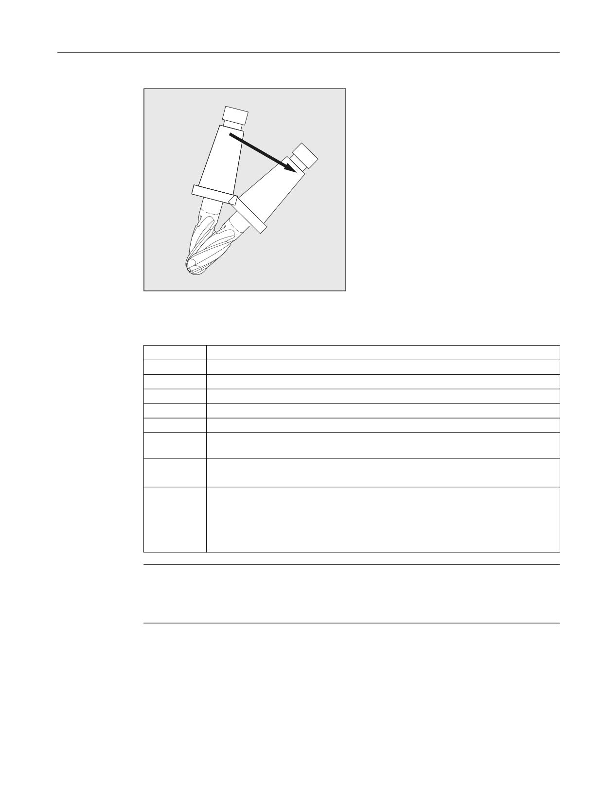
Tool offsets
11.6 Tool orientation (ORIC, ORID, OSOF, OSC, OSS, OSSE, ORIS, OSD, OST)
2ULHQWDWLRQ
FKDQJH
Programming tool orientation:
ORIC:
Orientation and path movement in parallel
ORID:
Orientation and path movement consecutively
OSOF:
No orientation smoothing
OSC:
Orientation constantly
OSS:
Orientation smoothing only at beginning of block
OSSE:
Orientation smoothing at beginning and end of block
ORIS:
Velocity of the orientation change with orientation smoothing activated in degrees per
mm (valid for OSS and OSSE)
OSD:
Smoothing of orientation by specifying smoothing distance with setting data:
SD42674 $SC_ORI_SMOOTH_DIST
OST:
Smoothing of orientation by specifying angular tolerance in degrees for vector interpo-
lation with setting data:
SD42676 $SC_ORI_SMOOTH_TOL
With rotary axis interpolation, the specified tolerance is assumed to be the maximum
variance of the orientation axes.
Note
All commands for smoothing the tool orientation (OSOF, OSC, OSS, OSSE, OSD, and OST) are
summarized in G group 34. They are modal; in other words, only one of these commands can
ever be effective at the same time.
Examples
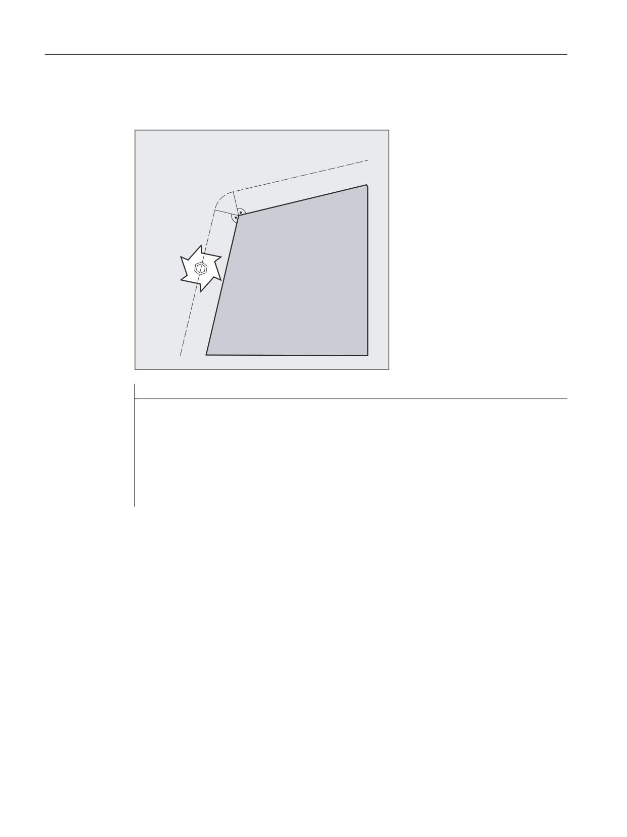
Example 1: ORIC
If two or more blocks with orientation changes are programmed between the traversing blocks
N10 and N20 (e.g. A2=... B2=... C2=...) programmed and ORIC is active, then the
Job Planning
Programming Manual, 12/2018, A5E40869460B AB
433
Tool offsets
11.6 Tool orientation (ORIC, ORID, OSOF, OSC, OSS, OSSE, ORIS, OSD, OST)
inserted circle block is distributed among these intermediate blocks according to the absolute
changes in angle.
1
1
1
1
Program code
Comment
ORIC
N8 A2=… B2=… C2=…
N10 X… Y… Z…
N12 C2=… B2=…
; The circle block inserted at the external corner is
distributed between N12 and N14, corresponding to the
N14 C2=… B2=…
change in orientation. The circular motion and the
orientation change are executed in parallel.
N20 X =…Y=… Z=… G1 F200
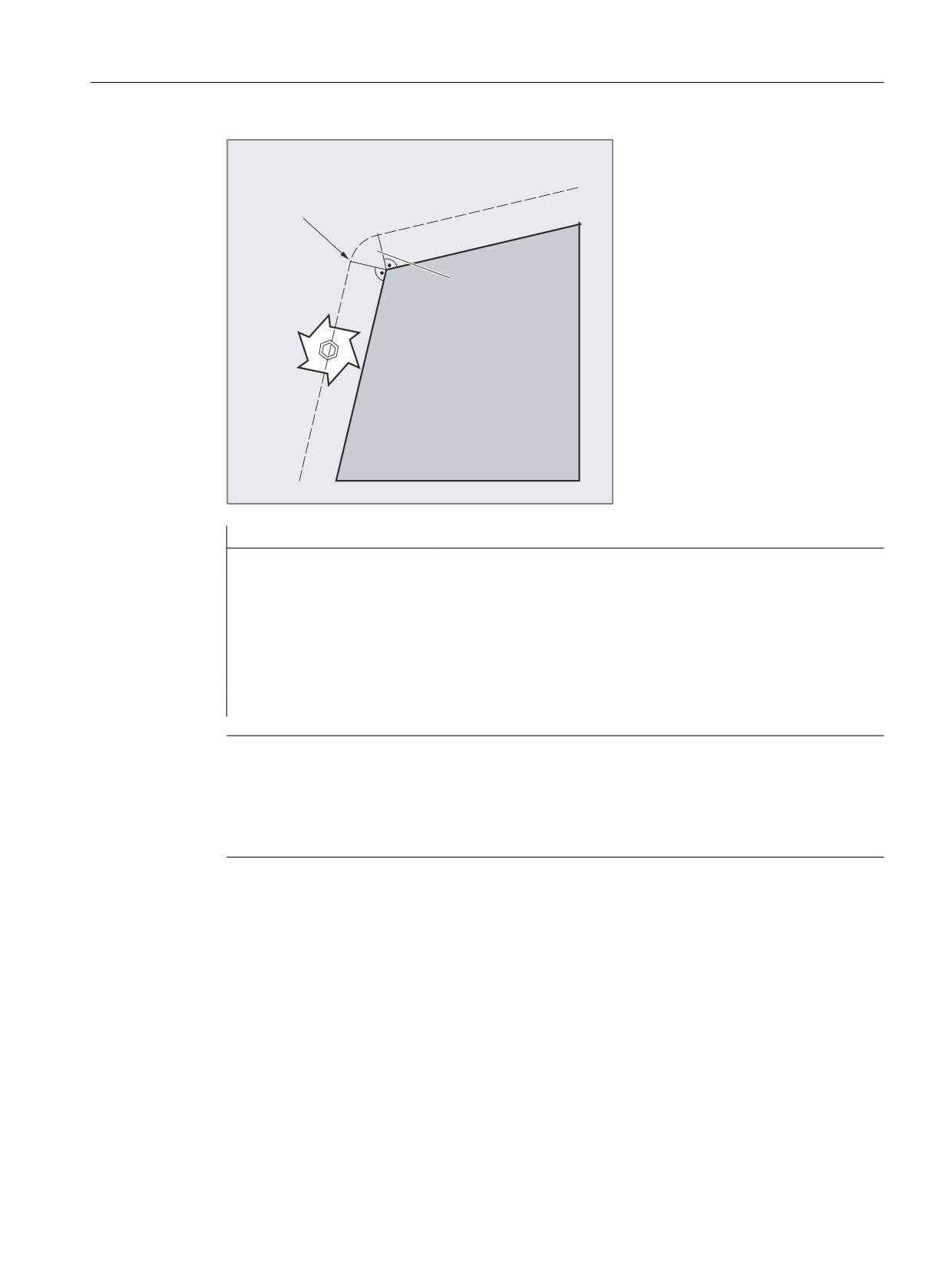
Example 2: ORID
If ORID is active, then all blocks between the two traversing blocks are executed at the end of
the first traversing block. The circle block with constant orientation is executed immediately
before the second traversing block.
Job Planning
434
Programming Manual, 12/2018, A5E40869460B AB
Tool offsets
11.6 Tool orientation (ORIC, ORID, OSOF, OSC, OSS, OSSE, ORIS, OSD, OST)
3HUIRUP 1 DQG 1
1
1
Program code
Comment
ORID
N8 A2=… B2=… C2=…
N10 X… Y… Z…
N12 A2=… B2=… C2=…
; The N12 and N14 blocks are executed at the end of N10.
The circle block is then executed with the actual orien-
tation.
N14 M20
; Help functions, etc.
N20 X… Y… Z…
Note
The method which is used to change orientation at an outer contour is determined using the
program command that is active in the first traversing block of an outer corner.
Without change in orientation: If the orientation is not changed at the block boundary, the cross-
section of the tool is a circle, which touches both of the contours.
Job Planning
Programming Manual, 12/2018, A5E40869460B AB
435
Tool offsets
11.6 Tool orientation (ORIC, ORID, OSOF, OSC, OSS, OSSE, ORIS, OSD, OST)
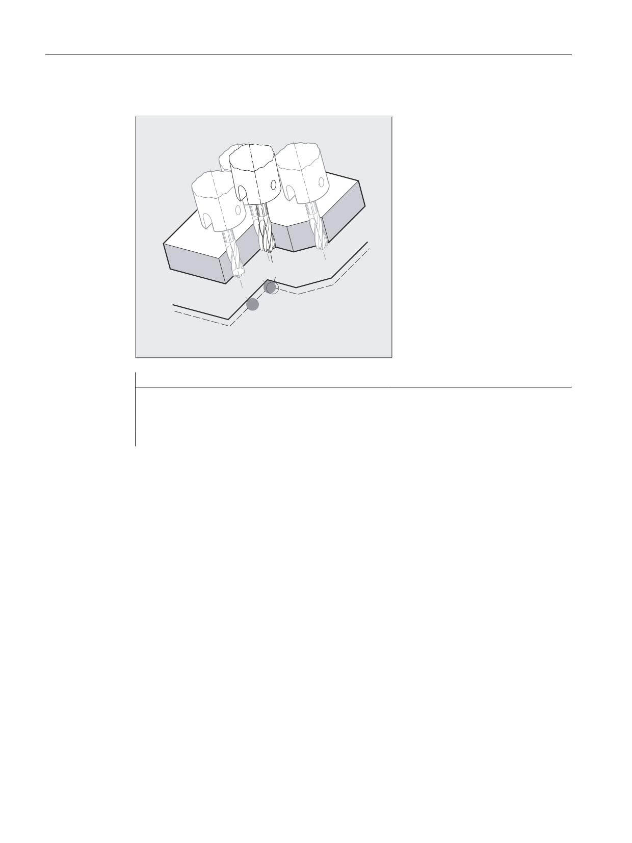
Example 3: Change in orientation at an inside corner
1
1
1
:5.
Program code
ORIC
N10 X …Y… Z… G1 F500
N12 X …Y… Z… A2=… B2=… C2=…
N15 X …Y… Z… A2=… B2=… C2=…
Further information
Behavior at outer corners
A circle block with the radius of the cutter is always inserted at an outside corner.
The ORIC and ORID program commands are used to determine whether changes in orientation
programmed between block N1 and N2 are executed before the inserted circle block is
processed or at the same time.
Job Planning
436
Programming Manual, 12/2018, A5E40869460B AB

Tool offsets
11.6 Tool orientation (ORIC, ORID, OSOF, OSC, OSS, OSSE, ORIS, OSD, OST)
$ FLUFXODU EORFN ZLOO EH DGGHG
EHWZHHQ EORFN 1 DQG 1
1
1
5
If an orientation change is required at outside corners, this can be performed either at the same
time as interpolation or separately together with the path movement.
When ORID is programmed, the inserted blocks are executed first without path motion. The
circle block generating the corner is inserted immediately before the second of the two
traversing blocks.
If several orientation blocks are inserted at an external corner and ORIC is selected, the circular
motion is distributed among the individual inserted blocks according to the absolute values of
the orientation changes.
Smoothing orientation with OSD or OST
When blending with G642, the maximum variance for the contour axes and orientation axes
cannot vary greatly. The smaller tolerance of the two determines the type of smoothing motion
and/or angular tolerance to smooth the orientation characteristic relatively strongly without
having to accept higher contour deviations.
OSD and OST can be activated to "generously" smooth very slight deviations from the
orientation characteristics with a specified smoothing distance and angular tolerance without
serious contour deviations.
Note
Unlike the process of rounding the contour (and orientation characteristics) with G642, when
rounding the orientation with OSD and/or OST, a separate block is not formed, instead the
rounding movement is added directly to the programmed original blocks.
With OSD and/or OST, block transitions cannot be rounded if there is a change in the type of
interpolation for tool orientation (vector → rotary axis, rotary axis → vector). These block
transitions can if necessary be rounded with the standard rounding functions G641, G642 and
G643.
Job Planning
Programming Manual, 12/2018, A5E40869460B AB
437
Tool offsets
11.7 Free assignment of D numbers, cutting edge numbers
11.7
Free assignment of D numbers, cutting edge numbers
11.7.1
Free assignment of D numbers, cutting edge numbers (CE address)
D number
The D numbers can be used as offset numbers. The number of the cutting edge can also be
addressed via the CE address. The cutting edge number can be written by the system variable
$TC_DPCE.
Default setting: Compensation no. == cutting edge no.
Machine data are used to define the maximum number of D numbers (cutting edge numbers)
and the maximum number of cutting edges per tool (→ machine manufacturer). The following
commands are only practical if the maximum cutting edge number (MD18105) was specified
to be greater than the number of cutting edges per tool (MD18106). Observe the machine
manufacturer’s specifications.
References
Function Manual Basic Functions; Tool Offset (W1)
11.7.2
Free assignment of D numbers: Checking D numbers (CHKDNO)
Using the CKKDNO command, you can check whether the existing D numbers were uniquely
assigned. The D numbers of all tools defined within a TO unit may not occur more than once.
No allowance is made for replacement tools.
Syntax
state=CHKDNO(Tno1,Tno2,Dno)
Meaning
state:
=TRUE:
The D numbers are assigned uniquely to the checked
areas.
= FALSE:
There was a D number collision or the parameters are
invalid. Tno1, Tno2 and Dno return the parameters
that caused the collision. These data can now be eval-
uated in the part program.
CHKDNO(Tno1,Tno2):
All D numbers of the part specified are checked.
CHKDNO(Tno1):
All D numbers of Tno1 are checked against all other tools.
CHKDNO:
All D numbers of all tools are checked against all other tools.
Job Planning
438
Programming Manual, 12/2018, A5E40869460B AB

Tool offsets
11.7 Free assignment of D numbers, cutting edge numbers
11.7.3
Free assignment of D numbers: Rename D numbers (GETDNO, SETDNO)
You must assign unique D numbers. Two different cutting edges of a tool must not have the
same D number.
GETDNO
This command returns the D number of a particular cutting edge (ce) of a tool with tool number
t. If no D number exists for the entered parameters, d=0 will be set. If the D number is invalid,
a value greater than 32000 is returned.
SETDNO
This command assigns the value d of the D number to a cutting edge (ce) of tool t. The result
of this statement is returned via state (TRUE or FALSE). If there is no data block for the
specified parameter, the value FALSE is returned. Syntax errors generate an alarm. The D
number cannot be set explicitly to 0.
Syntax
d = GETDNO (t,ce)
state = SETDNO (t,ce,d)
Meaning
d:
D number of the tool edge
t:
T number of the tool
ce:
Cutting edge number (CE number) of the tool
state:
Indicates whether the command could be executed (TRUE or FALSE).
Example for renaming a D number
Programming
Comment
$TC_DP2[1.2]=120
$TC_DP3[1,2]
= 5.5
$TC_DPCE[1,2] = 3
; Cutting edge number CE
N10 def int DNoOld, DNoNew = 17
N20 DNoOld = GETDNO(1,3)
N30 SETDNO(1,3,DNoNew)
The new D value 17 is then assigned to cutting edge CE=3. Now the data for the cutting edge
is addressed via D number 17; both via the system variables and in the programming with the
NC address.
Job Planning
Programming Manual, 12/2018, A5E40869460B AB
439
Tool offsets
11.7 Free assignment of D numbers, cutting edge numbers
11.7.4
Free assignment of D numbers: Determine T number to the specified D number
(GETACTTD)
The pre-defined function GETACTTD determines the T number associated with an absolute
D number. There is no check for uniqueness. If several D numbers within a TO unit are the
same, the T number of the first tool found in the search is returned.
Syntax
<Status>=GETACTTD(<TNo>,<DNo>)
Meaning
GETACTTD():
Function call
<DNo>:
D number for which the T number shall be searched.
Data type:
INT
<TNo>:
T number found
Data type:
VAR INT
<status>:
Result
Data type:
INT
Value:
0
The T number was found. <Tno> contains the value of the T
number.
-1
No T number exists for the specified D number; <Tno>=0.
-2
The D number is not absolute. <TNo> receives the value of
the first tool found that contains the D number with the value
<Dno>.
-5
The function was not able to be executed for another reason.
11.7.5
Free assignment of D numbers: Invalidate D numbers (DZERO)
The DZERO command is used for support during retooling. Compensation data sets tagged
with this command are no longer verified by the CHKDNO command. These data sets can be
accessed again by setting the D number once more with SETDNO.
Syntax
DZERO
Meaning
DZERO:
Marks all D numbers of the TO unit as invalid.
Job Planning
440
Programming Manual, 12/2018, A5E40869460B AB
Tool offsets
11.8 Toolholder kinematics
11.8
Toolholder kinematics
Requirements
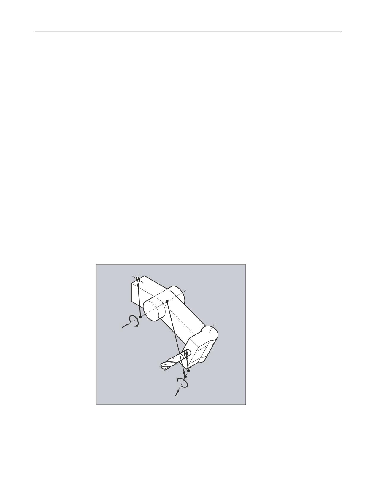
A toolholder can only orientate a tool in all possible directions in space if
● Two rotary axes V1 and V2 are present.
● The rotary axes are mutually orthogonal.
● The tool longitudinal axis is perpendicular to the second rotary axis V2.
In addition, the following requirement is applicable to machines for which all possible
orientations have to be settable:
● The tool longitudinal axis must be perpendicular to the first rotary axis V1.
Function
The toolholder kinematics with a maximum of two rotary axes v1 or v2 are defined using the 17
system variables $TC_CARR1[m] to $TC_CARR17[m]. The description of the toolholder
consists of:
● The vectoral distance from the first rotary axis of the toolholder I1, the vectoral distance
from the first rotary axis to the second rotary axis I2, the vectoral distance from the second
rotary axis to the reference point of the tool I3.
● The direction vectors of both rotary axes V1, V2.
● The angles of rotation α1, α2 around the two axes. The rotation angles are counted in
viewing direction of the rotary axis vectors, positive, in clockwise direction of rotation.
O
9
˞
O
O
˞
9
For machines with resolved kinematics (both the tool and the part can rotate), the system
variables have been extended with the entries $TC_CARR18[m] to $TC_CARR23[m].
Job Planning
Programming Manual, 12/2018, A5E40869460B AB
441
Tool offsets
11.8 Toolholder kinematics
Parameters
Function of the system variables for orientable toolholders
Designation
x component
y component
z component
l1 offset vector
$TC_CARR1[m]
$TC_CARR2[m]
$TC_CARR3[m]
l2 offset vector
$TC_CARR4[m]
$TC_CARR5[m]
$TC_CARR6[m]
v1 rotary axis
$TC_CARR7[m]
$TC_CARR8[m]
$TC_CARR9[m]
v2 rotary axis
$TC_CARR10[m]
$TC_CARR11[m]
$TC_CARR12[m]
α1 angle of rota-
$TC_CARR13[m]
tion
$TC_CARR14[m]
α2 angle of rota-
tion
l3 offset vector
$TC_CARR15[m]
$TC_CARR16[m]
$TC_CARR17[m]
Extensions of the system variables for orientable toolholders
Designation
x component
y component
z component
l4 offset vector
$TC_CARR18[m]
$TC_CARR19[m]
$TC_CARR20[m]
Axis identifier Ro-
Axis identifier of the rotary axes v1 and v2 (initialized with zero)
tary axis v1
$TC_CARR21[m]
Rotary axis v2
$TC_CARR22[m]
Kinematic type
$TC_CARR23[m]
Tool
Kinematics type T ->
Kinematics type P ->
Kinematics type M
Part
Only the tool can rotate
Only the part can rotate
Part and tool can rotate
Mixed mode
(default).
Offset of the
Angle in degrees of the rotary axes v1 and v2 on assuming the initial setting
Rotary axis v1
$TC_CARR24[m]
Rotary axis v2
$TC_CARR25[m]
Angle offset of
Offset of the Hirth tooth system in degrees for rotary axes v1 and v2
the rotary axis v1
$TC_CARR26[m]
Rotary axis v2
$TC_CARR27[m]
Angle increment
Offset of the Hirth tooth system in degrees for rotary axes v1 and v2
v1 rotary axis
$TC_CARR28[m]
v2 rotary axis
$TC_CARR29[m]
Min. position Ro-
Software limit for the minimum position of the rotary axes v1 and v2
tary axis v1
$TC_CARR30[m]
Rotary axis v2
$TC_CARR31[m]
Max. position Ro-
Software limits for the maximum position of the rotary axes v1 and v2
tary axis v1
$TC_CARR32[m]
Rotary axis v2
$TC_CARR33[m]
Toolholder name
A toolholder can be given a name instead of a number. $TC_CARR34[m]
User:
Intended use in user measuring cycles $TC_CARR35[m]
Axis name 1
$TC_CARR36[m]
Axis name 2
$TC_CARR37[m]
Identifier
$TC_CARR38[m]
$TC_CARR39[m]
$TC_CARR40[m]
Position
Fine
Parameters that can be added to the values
offset
in the basic parameters.
l1 offset vector
$TC_CARR41[m]
$TC_CARR42[m]
$TC_CARR43[m]
Job Planning
442
Programming Manual, 12/2018, A5E40869460B AB

Tool offsets
11.8 Toolholder kinematics
Extensions of the system variables for orientable toolholders
l2 offset vector
$TC_CARR44[m]
$TC_CARR45[m]
$TC_CARR46[m]
l3 offset vector
$TC_CARR55[m]
$TC_CARR56[m]
$TC_CARR57[m]
l4 offset vector
$TC_CARR58[m]
$TC_CARR59[m]
$TC_CARR60[m]
v1 rotary axis
$TC_CARR64[m]
v2 rotary axis
$TC_CARR65[m]
Note
Explanations of parameters
"m" specifies the number of the toolholder to be programmed.
$TC_CARR47 to $TC_CARR54 and $TC_CARR61 to $TC_CARR63 are not defined and
produce an alarm if read or write access is attempted.
The start/end points of the distance vectors on the axes can be freely selected. The rotation
angles α1, α2 around the two axes are defined in the initial state of the toolholder by 0°. In this
way, the kinematics of a toolholder can be programmed for any number of possibilities.
Toolholders with only one or no rotary axis at all can be described by setting the direction
vectors of one or both rotary axes to zero.
With a toolholder without rotary axis the distance vectors act as additional tool offsets whose
components cannot be affected by a change of machining plane (G17 to G19).
Parameter extensions
Parameters of the rotary axes
The system variables have been extended by the entries $TC_CARR24[m] to
$TC_CARR33[m] and described as follows:
Offset of rotary axes
Changing the position of the rotary axis v1 or v2 for the initial setting of the ori-
v1, v2
ented toolholder.
The angle offset/an-
The offset or the angle increment of the Hirth tooth system of the rotary axes
gle increment of the
v1 and v2. Programmed or calculated angle is rounded up to the next value that
rotary axes v1, v2
results from phi = s + n * d when n is an integer.
The minimum and
The minimum and maximum position of the rotary axis limit angle (software limit)
maximum position of
of the rotary axes v1 and v2.
the rotary axes v1, v2
Parameters for the user
$TC_CARR34 to $TC_CARR40 contain parameters that are freely available to users and up
to SW 6.4 were as standard, not further evaluated within the NCK or had no significance.
Fine offset parameters
$TC_CARR41 to $TC_CARR65 include fine offset parameters that can be added to the values
in the basis parameters. The fine offset value assigned to a basic parameter is obtained when
the value 40 is added to the parameter number.
Job Planning
Programming Manual, 12/2018, A5E40869460B AB
443
Tool offsets
11.8 Toolholder kinematics
Example
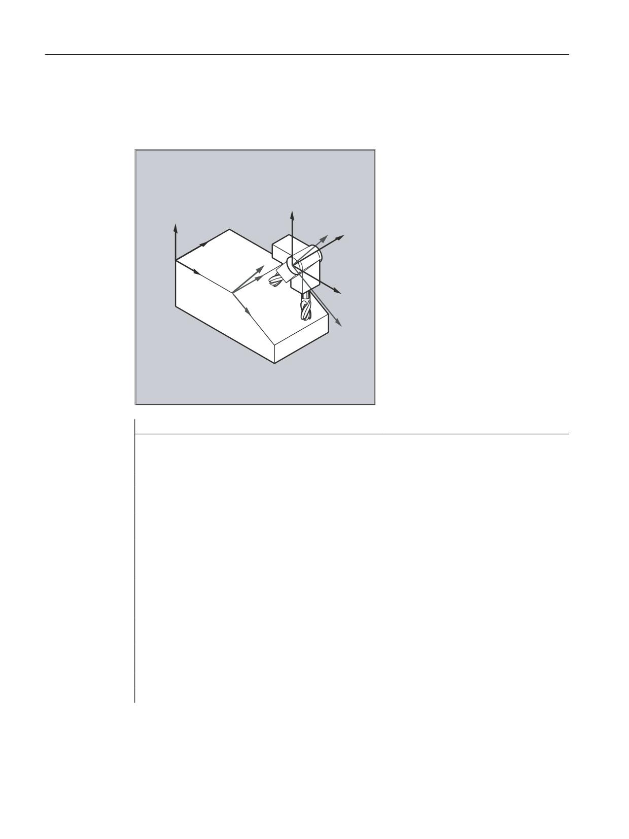
The toolholder used in the following example can be fully described by a rotation around the
Y axis.
]
]
=
<
<
=
;
<
;
;
;
Program code
Comment
N10 $TC_CARR8[1]=1
; Definition of the Y component of
the first rotary axis of toolholder
1.
N20 $TC_DP1[1,1] = 120
; Definition of a shaft miller.
N30 $TC_DP3[1,1]=20
; Definition of a shaft miller, 20
mm long.
N40 $TC_DP6[1,1]=5
; Definition of a shaft miller with
5 mm radius.
N50 ROT Y37
; Frame definition with 37° rota-
tion around the Y axis.
N60 X0 Y0 Z0 F10000
; Approach start position.
N70 G42 CUT2DF TCOFR TCARR=1 T1 D1 X10
Set radius compensation, tool
length compensation in rotated
frame, select toolholder 1, tool 1.
N80 X40
; Perform machining under a rota-
tion of 37°.
N90 Y40
N100 X0
N110 Y0
N120 M30
Job Planning
444
Programming Manual, 12/2018, A5E40869460B AB
Tool offsets
11.8 Toolholder kinematics
Further information
Resolved kinematics
For machines with resolved kinematics (both the tool as well as the workpiece can be rotated),
the system variables have been expanded by the entries $TC_CARR18[m] up to
$TC_CARR23[m] and are described as follows:
The rotatable tool table consisting of:
● The vectorial clearance of the second rotary axis V2 to the reference point of a tool table
that can be rotated I4 of the third rotary axis.
The rotary axes consisting of:
● The two channel identifiers for the reference of the rotary axes V1and V2, whose position
is, when required, accessed to determine the orientation of the toolholder that can be
orientated.
The type of kinematics with one of the values T, P or M:
● Kinematics type T: Only tool can rotate.
● Kinematics type P: Only part can rotate.
● Kinematics type M: Tool and part can rotate.
Clearing the toolholder data
Data of all toolholder data sets can be deleted using $TC_CARR1[0]=0.
The kinematic type $TC_CARR23[T]=T must be assigned with one of the three permissible
uppercase or lowercase letters (T,P,M) and for this reason, should not be deleted.
Changing the toolholder data
Each of the described values can be modified by assigning a new value in the part program.
Any character other than T, P or M results in an alarm when an attempt is made to activate
the toolholder that can be orientated.
Reading the toolholder data
Each of the described values can be read by assigning it to a variable in the part program.
Fine offsets
An illegal fine offset value is only detected if a toolholder that can be orientated is activated,
which contains such a value and at the same time setting data
SD42974 $SC_TOCARR_FINE_CORRECTION = TRUE.
The maximum permissible fine offset is limited to a permissible value in the machine data.
Job Planning
Programming Manual, 12/2018, A5E40869460B AB
445
Tool offsets
11.9 Tool length compensation for orientable toolholders (TCARR, TCOABS, TCOFR, TCOFRX, TCOFRY,
TCOFRZ)
11.9
Tool length compensation for orientable toolholders (TCARR,
TCOABS, TCOFR, TCOFRX, TCOFRY, TCOFRZ)
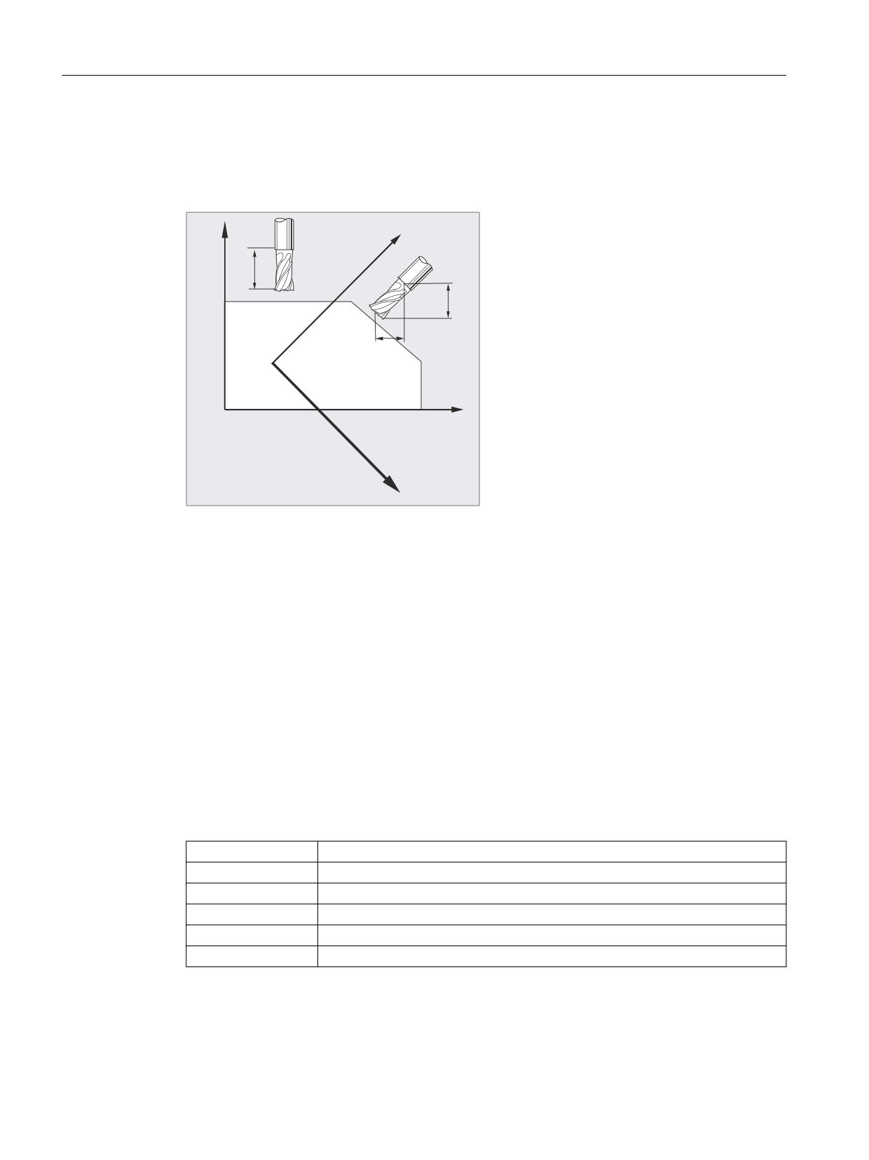
When the spatial orientation of the tool changes, its tool length components also change.
=
=
,
,
,
;
;
After a reset, e.g. through manual setting or change of the toolholder with a fixed spatial
orientation, the tool length components also have to be determined again. This is performed
using the TCOABS and TCOFR path commands.
For a toolholder of an active frame that can be orientated, when selecting the tool with TCOFRZ,
TCOFRY and TCOFRX, it is possible to define the direction in which the tool should point.
Syntax
TCARR=[<m>]
TCOABS
TCOFR
TCOFRZ
TCOFRY
TCOFRX
Meaning
TCARR=[<m>]:
Request toolholder with the number "m"
TCOABS:
Determine tool length components from the orientation of the current toolholder
TCOFR:
Determine tool length components from the orientation of the active frame
TCOFRZ:
Orientable toolholder from active frame with a tool pointing in the Z direction
TCOFRY:
Orientable toolholder from active frame with a tool pointing in the Y direction
TCOFRX:
Orientable toolholder from active frame with a tool pointing in the X direction
Job Planning
446
Programming Manual, 12/2018, A5E40869460B AB
Tool offsets
11.9 Tool length compensation for orientable toolholders (TCARR, TCOABS, TCOFR, TCOFRX, TCOFRY,
TCOFRZ)
Further information
Determine tool length offset from the orientation of the toolholder (TCOABS)
TCOABS calculates the tool length offset from the current orientation angles of the toolholder;
saved in the system variables $TC_CARR13 and $TC_CARR14.
For a definition of toolholder kinematics with system variables, see "Toolholder kinematics
(Page 441)".
In order to make a new calculation of the tool length offset when frames are changed, the tool
has to be selected again.
Tool direction from active frame
The toolholder with orientation capability is set so that the tool points in the following directions:
● With TCOFR or TCOFRZ in the Z direction
● With TCOFRY in the Y direction
● With TCOFRX in the X direction
The tool length offset is re-calculated when changing over between TCOFR and TCOABS.
Request toolholder (TCARR)
With TCARR, the toolholder number m is requested with its geometry data (compensation
memory).
With m=0, the active toolholder is deselected.
The geometry data of the toolholder only becomes active after a tool is called. The selected
tool remains active after a toolholder change has taken place.
The current geometry data for the toolholder can also be defined in the part program via the
corresponding system variables.
Recalculation of tool length offset (TCOABS) for a frame change
In order to make a new calculation of the tool length offset when frames are changed, the tool
has to be selected again.
Note
The tool orientation must be manually adapted to the active frame.
When the tool length offset is calculated, the angle of rotation of the toolholder is calculated
in an intermediate step. With toolholders with two rotary axes, there are generally two sets of
rotation angles, which can be used to adapt the tool orientation to the active frame; therefore,
Job Planning
Programming Manual, 12/2018, A5E40869460B AB
447
Tool offsets
11.9 Tool length compensation for orientable toolholders (TCARR, TCOABS, TCOFR, TCOFRX, TCOFRY,
TCOFRZ)
the rotation angle values stored in the system variables must at least correspond approximately
to the mechanically set rotation angles.
Note
Tool orientation
It is not possible for the control to check whether the rotation angles calculated by means of
the frame orientation are settable on the machine.
If the rotary axes of the toolholder are arranged such that the tool orientation calculated by
means of the frame orientation cannot be reached, then an alarm is output.
The combination of tool precision compensation and the functions for tool length offset on
movable toolholders is not permissible. If both functions are called simultaneously, an error
message is issued.
The TOFRAME function allows a frame to be defined on the basis of the direction of orientation
of the selected toolholder. For more information please refer to chapter "Frames".
When orientation transformation is active (3, 4 or 5-axis transformation), it is possible to select
a toolholder with an orientation deviating from the zero position without causing output of an
alarm.
Transfer parameter from standard and measuring cycles
For the transfer parameter of standard and measuring cycles, the following defined value
ranges apply.
For angular value, the value range is defined as follows:
● Rotation around 1st geometry axis: -180 degrees to +180 degrees
● Rotation around 2nd geometry axis: -90 degrees to +90 degrees
● Rotation around 3rd geometry axis: -180 degrees to +180 degrees
Refer to Chapter Frames, "Programmable rotation (ROT, AROT, RPL)".
Note
When transferring angular values to a standard or measuring cycle, the following should be
carefully observed:
Values less than the calculation resolution of the NC should be rounded-off to zero!
The calculation resolution of the NC for angular positions is defined in the machine data:
MD10210 $MN_INT_INCR_PER_DEG
Job Planning
448
Programming Manual, 12/2018, A5E40869460B AB

Tool offsets
11.10 Online tool length compensation (TOFFON, TOFFOF)
11.10
Online tool length compensation (TOFFON, TOFFOF)
Use the system variable $AA_TOFF[<n> ] to overlay the effective tool lengths in accordance
with the three tool directions three-dimensionally in real time.
The three geometry axis identifiers are used as index <n>. Thus, the number of active direction
offsets is determined by the geometry axes that are active at the same time.
All offsets can be active at the same time.
The online tool length offset function can be used for:
● Orientation transformation TRAORI
● Orientable toolholder TCARR
Note
Online tool length offset is an option, which must be enabled in advance. This function is
only practical in conjunction with an active orientation transformation or an active orientable
toolholder.
Syntax
TRAORI
TOFFON(<compensation direction>[,<offset value>])
WHEN TRUE DO $AA_TOFF[<compensation direction>]
; In synchronized actions.
TOFFOF(<compensation direction>)
For more information about programming online tool length offset in motion-synchronous
actions, see "Synchronized actions (Page 597)".
Meaning
TOFFON:
Activate online tool length offset
<compensation
Tool direction (X, Y, Z), in which the online tool length
direction>:
offset should be active.
<offset value>:
When activating, an offset value can be specified for
the relevant direction of compensation and this is im-
mediately recovered.
TOFFOF:
Reset online tool length offset
The compensation values in the specified compensation direction are reset and a pre-
processing stop is initiated.
Job Planning
Programming Manual, 12/2018, A5E40869460B AB
449
Tool offsets
11.10 Online tool length compensation (TOFFON, TOFFOF)
Examples
Example 1: Selecting the tool length compensation
Program code
Comment
MD21190 $MC_TOFF_MODE = 1
; Absolute values are approached.
MD21194 $MC_TOFF_VELO[0] =1000
MD21196 $MC_TOFF_VELO[1] =1000
MD21194 $MC_TOFF_VELO[2] =1000
MD21196 $MC_TOFF_ACCEL[0] =1
MD21196 $MC_TOFF_ACCEL[1] =1
MD21196 $MC_TOFF_ACCEL[2] =1
N5 DEF REAL XOFFSET
N10 TRAORI(1)
; Transformation on.
N20 TOFFON(Z)
; Activation of online tool length
compensation for the Z tool direc-
tion.
N30 WHEN TRUE DO $AA_TOFF[Z]=10 G4 F5
; A TLC of 10 is interpolated for the
Z tool direction.
N100 XOFFSET=$AA_TOFF_VAL[X]
; Assigns actual compensation in the
X direction.
N120 TOFFON(X,-XOFFSET) G4 F5
; For the X tool direction, the TLC
is reduced back to 0.
Example 2: Deselect the tool length offset
Program code
Comment
N10 TRAORI(1)
; Transformation on.
N20 TOFFON(X)
; Activation of online tool length
compensation for the X tool direc-
tion.
N30 WHEN TRUE DO $AA_TOFF[X]=10 G4 F5
; A TLC of 10 is interpolated for the
X tool direction.
N80 TOFFOF(X)
; Position offset of the X tool di-
rection is deleted:
...$AA_TOFF[X]=0
No axis is moved.
The position offset is added to the
actual position in the Work corre-
sponding to the
actual orientation.
Job Planning
450
Programming Manual, 12/2018, A5E40869460B AB
Tool offsets
11.10 Online tool length compensation (TOFFON, TOFFOF)
Further information
Block preparation
During block preparation in preprocessing, the current tool length offset active in the main run
is also taken into consideration. To allow extensive use to be made of the maximum permissible
axis velocity, it is necessary to stop block preparation with a STOPRE preprocessing stop while
a tool offset is established.
The tool offset is always known at the time of run-in when the tool length offsets are not changed
after program start or if more blocks have been processed after changing the tool length offsets
than the IPO buffer can accommodate between run-in and main run.
Variable $AA_TOFF_PREP_DIFF
The dimension for the difference between the currently active compensation in the interpolator
and the compensation that was active at the time of block preparation can be polled in the
variable $AA_TOFF_PREP_DIFF[<n>].
Adjusting machine data and setting data
The following system data is available for online tool length offset:
● MD20610 $MC_ADD_MOVE_ACCEL_RESERVE (acceleration margin for overlaid motion)
● MD21190 $MC_TOFF_MODE
Content of system variable $AA_TOFF[<n>] is moved through as absolute value or is
integrated up.
● MD21194 $MC_TOFF_VELO (velocity of the online tool length offset)
● MD21196 $MC_TOFF_ACCEL (acceleration of the online tool length offset)
● Setting data for presetting limit values
:
SD42970 $SC_TOFF_LIMIT (upper limit of the tool length offset value)
Reference:
Function Manual, Special Functions; F2: Multi-axis transformations
Job Planning
Programming Manual, 12/2018, A5E40869460B AB
451
Tool offsets
11.11 Modification of the offset data for rotatable tools
11.11
Modification of the offset data for rotatable tools
11.11.1
Calculating orientations (ORISOLH)
The predefined ORISOLH function helps the user to set the rotary axis positions of a machine
so that a turning tool can be brought into a defined, kinematic-independent position relative to
the workpiece. Prerequisite is that a 6-axis transformation is active that has been
parameterized with kinematic chains.
Two basic functions are available:
● Tool alignment
The β and γ angles are specified. The function calculates the angles of the three orientation
axes required for this.
● Direct tool alignment
The angles of the second and third orientation axes are specified. The function calculates
the associated β and γ angles as well as that of the missing first orientation axis.
Note
Order of the orientation axes
If you run through the kinematic chain that describes the structure of the machine, from the
workpiece to the tool, then the following specifications apply for the order of the three
orientation axes of a 6-axis transformation:
● The orientation axis that is closest to the workpiece is the first orientation axis.
● The orientation axis that is closest to the tool is the third orientation axis.
Generally, the first orientation axis is a spindle and the corresponding rotation is therefore
implemented in these cases through a rotating frame.
Syntax
<RetVal> = ORISOLH(<Cntrl>,<W1>,<W2>)
Job Planning
452
Programming Manual, 12/2018, A5E40869460B AB

Tool offsets
11.11 Modification of the offset data for rotatable tools
Meaning
ORISOLH:
Function call
<RetVal>:
Function return value
Data type:
INT
Range of val-
0, -2, -3, ..., -17
ues:
Values:
0
Function has ended without an error.
-2
No valid transformation (6-axis orientation transformation) is
active.
-3
The first parameter (<Cntrl>) is negative.
-4
The unit position of the first parameter (<Cntrl>) is invalid.
Only the values 0 and 1 are permissible.
-5
The tens position of the first parameter (<Cntrl>) is invalid.
Only the values 0 to 3 are permissible.
-6
The hundreds position of the first parameter (<Cntrl>) is in-
valid.
Only the values 0 and 1 are permissible.
-7
The thousands position of the first parameter (<Cntrl>) is in-
valid.
Only the values 0 to 3 are permissible.
-8
Angle γ is too large for the "Direct tool alignment" function.
-9
At least one of the specified axis positions violates an axis
limit for the "Direct tool alignment" function.
-10
No tool is active.
-11
The requested orientation cannot be set.
-12
The adaptation of the free axis angle for the Hirth joint is not
possible for the first or only solution.
-13
The adaptation of the free axis angle for the Hirth joint is not
possible for the second solution.
-14
The adaptation of the free axis angle for the Hirth joint is not
possible for either of the two solutions.
-15
The first orientation axis is parameterized as Hirth axis.
-16
The second as well as the third rotary axis has been para-
meterized as Hirth axis. Only one of the two axes can be the
Hirth axis.
-17
At least one of the specified axis positions is not compatible
with the associated Hirth joint for the "Swivel directly" func-
tion.
Job Planning
Programming Manual, 12/2018, A5E40869460B AB
453
Tool offsets
11.11 Modification of the offset data for rotatable tools
<Cntrl>:
Controls the behavior of the function
Data type:
INT
The <Cntrl> parameter is decimal coded (unit to thousands position):
Unit position:
The unit position controls the response to errors.
xxx0
In the event of an error (return value < 0), alarm 14106 is
output and program processing is aborted.
Note:
The alarm is also output irrespective of the value of the unit
position when the <Cntrl> parameter is negative.
xxx1
In the event of an error (return value < 0) no alarm is output.
The user can react suitably in the program.
Tens position:
Controls the behavior when an orientation axis with Hirth joint is
present.
Note:
This parameter is only evaluated for the "Tool alignment" function
(i.e. when the hundreds position has the value "0").
xx0x
The axis position is rounded off to the nearest position.
xx1x
The axis positions are rounded off so that the difference of
the β angle to its programmed value is minimal.
xx2x
The axis positions are rounded off so that the β angle is equal
to the highest possible value which is less than the program-
med value (β is rounded down).
xx3x
The axis positions are rounded off so that the β angle is equal
to the lowest possible value which is greater than the pro-
grammed value (β is rounded up).
Hundreds posi-
Specifies which function is to be executed or the significance of the
tion:
two following parameters <W1> and <W2>.
x0xx
"Tool alignment" function
Parameters <W1> and <W2> have the following meaning:
● <W1> = β
● <W2> = γ
The associated angles of the orientation axes are calculated.
x1xx
"Direct tool alignment" function
<W1> is the position specification for the second orientation
axis, <W2> is the position specification for the third orienta-
tion axis of a 6-axis transformation. The position of the first
orientation axis and the β and γ angles are defined which are
compatible with the two position specifications.
If no error occurs, two solutions are always output in the
$P_ORI_POS[<n>, <m>] system variables. The first index
<n> (0 or 1) refers to the solution and the second index <m>
(0 ... 2) to the orientation axis:
● $P_ORI_POS[0/1, 0]: Position of the first orientation axis
● $P_ORI_POS[0/1, 1]: Angle β
● $P_ORI_POS[0/1, 2]: Angle γ
A check is made as to whether the position specifications
<W1> and <W2> are compatible with any Hirth joints or active
software limits. If this is not the case, a corresponding error
number is returned (see <RetVal> parameter).
Job Planning
454
Programming Manual, 12/2018, A5E40869460B AB

Tool offsets
11.11 Modification of the offset data for rotatable tools
If the angles <W1> and <W2> are selected arbitrarily, the
cutting edge of the tool is generally not in the machining
plane. The angle γ through which the cutting edge is rotated
out of the machining plane, must not be greater than the limit
value which is defined by the setting data SD42999 $SC_OR-
ISOLH_INCLINE_TOL.
Thousands po-
Specifies which positions of the solutions may be modified when the
sition:
hundreds position has the value "0", i.e. for the "Tool alignment"
function.
0xxx
The calculated axis positions should be as close as possible
to the current machine axis positions.
1xxx
The calculated axis positions for modulo axes should be as
close as possible to the middle of the modulo range, for other
axes as close as possible to 0. For non-modulo axes, this
means that the axis positions are reduced to the range
-180° … +180°.
2xxx
The calculated axis positions should be reduced to the range
-180° … +180° irrespective of the axis type.
<W1>:
First angle
The meaning results from the hundreds position of the <Cntrl> paramter.
Data type:
REAL
<W1>:
Second angle
The meaning results from the hundreds position of the <Cntrl> paramter.
Data type:
REAL
Note
Parameters that have not been programmed have the default value "0".
Job Planning
Programming Manual, 12/2018, A5E40869460B AB
455
Tool offsets
11.11 Modification of the offset data for rotatable tools
Further information
The number of solutions found together with further status information when executing the
ORISOLH function, can be read via the following system variables:
System variable
Meaning
$P_ORI_POS
Returns the angles of the orientation axes that result from the orientation program-
[<n>, <m>]
ming.
<n>:
Index of the solution
Range of values:
0, 1
<m>:
Index of the orientation axis
Range of values:
0 ... 2
The order of the orientation axes (1 ... 3) refers to the
definition of the axes in $NT_ROT_AX_NAME.
When the ORISOLH function is called in the "Direct tool alignment" mode, the
$P_ORI_POS[0/1, 1] and P_ORI_POS[0/1, 2] variables contain the values of the
two angles β and γ belonging to the two solutions.
The first solution entered in $P_ORI_POS[<n>, <m>], i.e. with the index <n> = 0, is
always the solution that is selected by the control when the requested orientation
is approached directly. The second index <m> refers to the orientation axis, i.e. on
$NT_ROT_AX_NAME.
The axis positions entered in $P_ORI_POS[<n>, <m>] take into account the offsets
entered in $NK_OFF and $NK_OFF_FINE, i.e. these axis angles can be used in the
following blocks to set the required orientation without any further modification.
If a rotary axis is a Hirth axis, the solution positions are rounded off to the nearest
position of rest of the Hirth joint. For Hirth jointed rotary axes, you can read the
differences between the axis positions for the exact solutions and those of the sol-
utions adapted to the Hirth incrementing in the $P_ORI_DIFF system variable.
$P_ORI_DIFF
Returns the difference between the exact positions of the orientation axes and those
[<n>, <m>]
provided in $P_ORI_POS that result from the orientation programming.
<n>:
Index of the solution
Range of values:
0, 1
<m>:
Index of the orientation axis
Range of values:
0 ... 2
The order of the orientation axes (1 ... 3) refers to the
definition of the axes in $NT_ROT_AX_NAME.
The content can only be not equal to zero when the positions are incremented (Hirth
joint), i.e. when the system data $NT_HIRTH_INCR of the relevant axis is not equal
to zero and when this axis is a manual rotary axis.
Job Planning
456
Programming Manual, 12/2018, A5E40869460B AB
Tool offsets
11.11 Modification of the offset data for rotatable tools
System variable
Meaning
$P_ORI_SOL
If for an orientation transformation with more than one orientation axis, the axis
angles are calculated that should result in a specified orientation, there is generally
more than one solution. The $P_ORI_SOL system variables contain the number of
valid solutions together with additional status information.
The content of $P_ORI_SOL is coded as follows:
Values < 0
General error states
-1
No solutions have been calculated yet for the active transfor-
mation (missing call of ORISOLH).
-2
A transformation is not active, or the active transformation is
not an orientation transformation (6-axis transformation) that
can provide positions for a specified orientation programming.
-4
The desired orientation cannot be set with the present kine-
matics.
-5
No solution was found when the ORISOLH function was called
in the "Direct tool alignment" mode.
-6
Angle γ is too large when the ORISOLH function was called
in the "Direct tool alignment" mode.
-7
An angle was specified when the ORISOLH function was
called in the "Direct tool alignment" mode that cannot be set
because of the Hirth joint.
-8
The first orientation axis (frame axis) must not be parameter-
ized as Hirth axis.
-9
The second as well as the third rotary axis has been parame-
terized as Hirth axis. Only one of the two axes can be the Hirth
axis.
-10
No adaptation of the solution(s) to the Hirth joint has been
found.
Values > 0
Number of mathematically possible solutions without consideration
of axis limits and any error conditions.
Unit position
0
There is no solution, i.e. the requested orientation cannot be
set.
There can be three different causes for this case:
● In principle, the requested orientation cannot be achieved
because of the machine kinematics (orientation axes not
arranged at right angles) even with an arbitrary traversing
range of the orientation axes. In this case, the tens and
hundreds positions of $P_ORI_SOL are both zero, the
$P_ORI_STAT status variables assigned to the orientation
axis have the value "-4".
● The calculated solutions cannot be achieved because they
would violate the axis limits. The positions of the
orientation axes that would result without the axis limits,
can be read in $P_ORI_POS.
● Axis positions were specified when the ORISOLH function
was called in the "Direct tool alignment" mode which would
result in either the orientation vector or the orientation
normal vector of the tool being aligned parallel to the first
orientation axis, whose position is to be calculated. The
position of this axis is not defined in these cases.
Job Planning
Programming Manual, 12/2018, A5E40869460B AB
457
Tool offsets
11.11 Modification of the offset data for rotatable tools
System variable
Meaning
1
There is a solution.
There can be three different causes for this case:
● Based on the specified orientation and the machine
kinematics, there is only one solution (from the
mathematical point of view, two coinciding solutions) even
without consideration of the axis limits. This case occurs
at the edge of the orientation range for kinematics that are
not at right angles. $P_ORI_POS contains both (identical)
solutions.
● There is only one solution because a second solution is
invalid due to the violated axis limits. The valid solution is
always the first solution in $P_ORI_POS. The second
solution which would result when the axis limits are not
taken into account, can also be read in $P_ORI_POS.
● This is the normal case when the ORISOLH function is
called in the "Direct tool alignment" mode. For the specified
axis positions of two orientation axes, there is generally
only one valid position for the missing orientation axis to
be calculated.
2
There are two solutions.
8
There are an infinite number of solutions, i.e. the position of
an orientation axis (the polar axis) is arbitrary. However, from
the two possible positions of the other axes, one is excludes
because of the violated axis limits.
9
There are an infinite number of solutions, i.e. the position of
an orientation axis (the polar axis) is indefinite. The indefinite
axis can be determined from the hundreds position or from the
$P_ORI_STAT system variable.
Values > 0
Bit-coded display for violated axis limits. The precise cause of the
error can be determined from the $P_ORI_STAT system variable.
Tens posi-
tion
Bit 0 (value 10):
For at least one solution, at least one axis limit
of the first orientation axis is violated.
Bit 1 (value 20):
For at least one solution, at least one axis limit
of the second orientation axis is violated.
Bit 2 (value 40):
For at least one solution, at least one axis limit
of the third orientation axis is violated.
Values > 0
Bit-coded display for non-defined axis positions (can only occur when
there is an infinite number of solutions, i.e. when the unit position is
Hundreds
equal to "9").
position
Bit 0 (value 100):
The position of the first orientation axis is not de-
fined.
Bit 1 (value 200):
The position of the second orientation axis is not
defined.
Bit 2 (value 400):
The position of the third orientation axis is not
defined.
The designations first, second and third orientation axis refer to the definition of the
axes in $NT_ROT_AX_NAME.
Job Planning
458
Programming Manual, 12/2018, A5E40869460B AB
Tool offsets
11.11 Modification of the offset data for rotatable tools
System variable
Meaning
$P_ORI_STAT
Returns the status for each of the maximum three orientation axes after ORISOLH
[<n>]
has been called.
<n>:
Index of the orientation axis
(correspnds to the index of the relevant orientation axis in
$NT_ROT_AX_NAME)
Range of values:
0 ... 2
The order of the orientation axes (1 ... 3) refers to the
definition of the axes in $NT_ROT_AX_NAME.
The content of $P_ORI_STAT is coded as follows:
Values < 0
General error states
-1
The status is not defined (missing call of ORISOLH).
-2
A transformation is not active, or the active transformation is
not an orientation transformation (6-axis transformation) that
can provide positions for a specified orientation programming.
-3
The axis is not included in the active transformation.
-4
The position of the axis cannot be calculated because the re-
quested orientation cannot be achieved with the present kin-
ematics even with an arbitrary assumed traversing range of
the axis.
-5
Axis positions were specified when the ORISOLH function
was called in the "Direct tool alignment" mode which would
result in either the orientation vector or the orientation normal
vector of the tool being aligned parallel to the first orientation
axis, whose position is to be calculated. The position of this
axis is not defined in these cases.
-6
Angle γ is too large when the ORISOLH function was called
in the "Direct tool alignment" mode.
-7
An angle was specified when the ORISOLH function was
called in the "Direct tool alignment" mode that cannot be set
because of the Hirth joint.
-8
The first orientation axis (frame axis) must not be parameter-
ized as Hirth axis.
-9
The second as well as the third rotary axis has been parame-
terized as Hirth axis. Only one of the two axes can be the Hirth
axis.
-10
No adaptation of the solution(s) to the Hirth joint has been
found.
Values > 0
Bit-coded display for violated axis limits of the first solution.
Unit position
Bit 0 (value 1):
The first solution violates the lower axis limit.
Bit 1 (value 2):
The first solution violates the upper axis limit.
Values > 0
Bit-coded display for violated axis limits of the second solution.
Tens posi-
Bit 0 (value 10):
The second solution violates the lower axis limit.
tion
Bit 1 (value 20):
The second solution violates the upper axis limit.
Values > 0
Display of a non-defined axis position.
Hundreds
Bit 0 (value 100):
The position of the orientation axis is not defined,
position
i.e. the requested orientation is achieved with
each arbitrary setting of the rotary axis (polar po-
Job Planning
Programming Manual, 12/2018, A5E40869460B AB
459

Tool offsets
11.11 Modification of the offset data for rotatable tools
System variable
Meaning
sition). This information is also contained in the
$P_ORI_SOL system variable.
Of the error numbers that indicate a violation of the axis limits, several can occur
simultaneously. When an axis limit is violated, an attempt is made to reach a position
within the permissible axis limits by adding or subtracting multiples of 360°. If this
is not possible, it is not clearly defined whether the lower or the upper axis limit has
been violated.
If there is no solution for the requested orientation ($P_ORI_SOL = 0), the status of
the orientation axes in the transformation is "0".
Note
$NT_ROT_AX_NAME
This system variable refers to a maximum of three axes used for setting the orientation. It
contains the names of the chain elements ($NK_NAME) that define the machine axes (rotary
axes) that must perform the orientation movements resulting from a kinematic transformation.
The order in which the maximum three rotary axes are contained in this system variable is
irrelevant for the machine kinematics because this is derived from the structure of the kinematic
chains. However, as it defines the order in which other variables access the rotary axes, the
order of the orientation axes in $NT_ROT_AX_NAME must match the kinematic description.
Note
Status information
The status information that shows, for example, that an orientation cannot be achieved or can
only be achieved when relevant axis limits are violated, does not trigger an NC alarm. It is the
responsibility of the user to react suitably to the specified conditions.
11.11.2
Activating the modification of the offset data for rotatable tools (CUTMOD,
CUTMODK)
The modification of the offset data for rotatable tools is activated in the NC program via the
CUTMOD (in combination with orientable tool carriers) or CUTMODK language command (for
orientation transformations that were defined by means of kinematic chains).
Note
As the orientable tool carriers and orientation transformations that were defined by means of
kinematic chains cannot be active at the same time, there are no conflicts between the two
variants.
Syntax
CUTMOD = <Value>
or
Job Planning
460
Programming Manual, 12/2018, A5E40869460B AB

Tool offsets
11.11 Modification of the offset data for rotatable tools
CUTMODK = <Command>
Meaning
CUTMOD:
Function call in combination with orientable tool carriers
<Value>:
Assigned value
Data type:
INT
Value:
0
The function is deactivated.
The values supplied from system variables $P_AD... are the same
as the corresponding tool parameters.
> 0
The function is activated if an orientable tool carrier with the speci-
fied number is active, i.e. the activation is linked to a specific ori-
entable tool carrier.
The values supplied from system variables $P_AD... may be modi-
fied with respect to the corresponding tool parameters depending
on the active rotation.
The deactivation of the designated orientable tool carrier tempo-
rarily deactivates the function; the activation of another orientable
tool carrier permanently deactivates it. This is the reason why in
the first case, the function is re-activated when again selecting the
same orientable tool carrier; in the second case, a new selection
is required - even if at a subsequent time, the orientable tool carrier
is re-activated with the specified number.
The function is not influenced by a reset.
-1
The function is always activated if an orientable tool carrier is ac-
tive.
When changing the tool carrier or when de-selecting it and a sub-
sequent new selection, CUTMOD does not have to be set again.
-2
The function is always activated if an orientable tool carrier is ac-
tive whose number is the same as the currently active orientable
tool carrier.
If an orientable tool carrier is not active, then this has the same
significance as CUTMOD=0.
If an orientable tool carrier is active, then this has the same signif-
icance as when directly specifying the actual tool carrier number.
< -2
Values less than 2 are ignored, i.e. this case is treated as if CUT-
MOD was not programmed.
Note:
This value range should not be used as it is reserved for possible
subsequent expansions.
CUTMODK:
Function call in combination with orientation transformations that have been defined by
means of kinematic chains
Job Planning
Programming Manual, 12/2018, A5E40869460B AB
461

Tool offsets
11.11 Modification of the offset data for rotatable tools
<Command>:
Assigned Command
Data type:
STRING
Value:
"NEW"
The states of an active transformation defined with kinematic
chains relevant for the "Modification of the offset data", the
name of the transformation and the current contour frame
are saved.
Note:
This command is only permissible when a suitable transfor-
mation (TRAORI_DYN, TRAORI_STAT or TRAANG_K) is
active.
"OFF"
Switches the active "Modification of the offset data" off. The
data previously stored with "NEW" is retained.
Note:
This command is also permissible when CUTMODK is not
active. It then remains without effect. Any data set present
for the "Modification of the offset data" is retained.
"ON"
With this command, the "Modification of the offset data" is
re-activated with a data set previously stored with the "NEW"
command.
If a transformation with the name of the stored data set is
active when this command is executed, the "Modification of
the offset data" takes effect immediately. Otherwise, the ac-
tivation is delayed until an active transformation is activated.
"CLEAR"
As with the "OFF" command, switches the "Modification of
the offset data" off and also deletes the stored data set.
Note:
This command is also permissible when CUTMODK is not
active.
Note
SD42984 $SC_CUTDIRMOD
The CUTMOD or CUTMODK command replaces the function that can be activated using the
setting data SD42984 $SC_CUTDIRMOD. However, this function remains available
unchanged. However, as it doesn't make sense to use both functions in parallel, it can only be
activated if CUTMOD is equal to zero and CUTMODK is the zero string.
Further information
Reading modified offset data
The modified offset data is provided in the following system variables and OPI variables:
Meaning
System variable
OPI variable
Cutting edge position
$P_AD[2]
cuttEdgeParam2
Holder angle
$P_AD[10]
cuttEdgeParam10
Cut direction
$P_AD[11]
cuttEdgeParam11
Clearance angle
$P_AD[24]
cuttEdgeParam24
Job Planning
462
Programming Manual, 12/2018, A5E40869460B AB

Tool offsets
11.11 Modification of the offset data for rotatable tools
The data is always modified with respect to the corresponding tool parameters
($TC_DP2[..., ...] etc.) when the "Modification of the offset data for rotatable tools" function
was activated with the CUTMOD or CUTMODK command and the tool was rotated by an orientable
tool carrier or a suitable orientation transformation.
Further function-relevant system variables
System variable
Meaning
$P_CUTMOD_ANG /
Returns the angle through which a tool was rotated in the active machining
plane and the modified cutting edge data available for the CUTMOD and
$AC_CUTMOD_ANG
CUTMODK functions.
$P_CUTMOD /
Reads the currently valid value that was last programmed with the CUTMOD
command (number of the tool carrier for which the modification of the offset
$AC_CUTMOD
data should be activated).
If the last programmed value was CUTMOD = -2 (activation with the currently
active orientable tool carrier), then the value "-2" is not returned in the system
variable, but rather the number of the orientable tool carrier active at the time
of programming.
$P_CUTMODK /
Reads the name of the transformation under which the currently valid data set
for the "Modification of the offset data" was created.
$AC_CUTMODK
$P_CUT_INV /
Supplies the value TRUE if the tool is rotated so that the spindle direction of
rotation must be inverted. To do this, the following four conditions must be
$AC_CUT_INV
fulfilled in the block to which the read operations refer:
1. If a turning or grinding tool is active
(tool types 400 to 599 and / or SD42950 $SC_TOOL_LENGTH_TYPE = 2).
2. The modification of the offset data was activated with the CUTMOD or
CUTMODK command.
3. An orientable tool carrier or an orientation transformation defined with
kinematic chains is active, which was selected with the CUTMOD or
CUTMODK command.
4. The tool is rotated by the orientable tool carrier or the kinematic orientation
transformation so that the resulting normal of the tool cutting edge is
rotated with respect to the initial position by more than 90° (typically 180°).
If at least one of the specified four conditions is not fulfilled, the variable returns
the value FALSE. For tools whose cutting edge position is not defined, the
value of the variable is always FALSE.
Job Planning
Programming Manual, 12/2018, A5E40869460B AB
463

Tool offsets
11.11 Modification of the offset data for rotatable tools
System variable
Meaning
$P_CUTMOD_ERR
Error state after the last call of the CUTMOD function
The CUTMOD function can also be called implicitly for a tool change. At a
reset, the variable is reset to zero. It is reset at every tool change and, if
required, rewritten.
The variable is bit-coded. The bits have the following meanings:
Bit 0:
No valid cut direction is defined for the active tool.
Bit 1:
The cutting edge angle (clearance angle and holder angle) of the
active tool are both zero.
Bit 2:
The clearance angle of the active tool has an impermissible value (<
0° or > 180°).
Bit 3:
The holder angle of the active tool has an impermissible value (< 0°
or > 90°).
Bit 4:
The plate angle of the active tool has an impermissible value (< 0° or
> 90°).
Bit 5:
The cutting edge position - holder angle combination of the active tool
is not permitted (the holder angle must be ≤ 90° for cutting edge po-
sition 1 to 4; for cutting edge positions 5 to 8 it must be ≥ 90°).
Bit 6:
Illegal rotation of the active tool.
The tool was rotated out of the active machining plane by ± 90° (with
a tolerance of about 1°). The cutting edge position is therefore no
longer defined in the machining plane.
Bit 7:
The cutting plate is not in the machining plane and the angle between
the cutting plate and the machining plane exceeds the upper limit
specified with the setting data SD42998 $SC_CUT-
MOD_PLANE_TOL.
Bit 8:
The cutting plate is not in the machining plane. Angle α is greater than
1°. Angle α is the angle of rotation around the coordinate axis which
is perpendicular to the axis of rotation of angle β as well as to the axis
of rotation of angle γ (the X axis for G18).
$P_...: Preprocessing variables
$AC_...: Main run variables
All main run variables can be read in synchronized actions. A read access operation from the
preprocessing generates a preprocessing stop.
Plane change
To determine the modified cutting edge position, cutting direction and holder or clearance
angle, the evaluation of the cutting edge in the active plane (G17 - G19) is decisive.
However, if setting data SD42940 $SC_TOOL_LENGTH_CONST (change of the tool length
component when selecting the plane) has a valid non-zero value (plus or minus 17, 18 or 19),
its contents define the plane in which the relevant quantities are evaluated.
This priority rule of the setting data over the G code can be deactivated by setting bit 18 of the
machine data $MC_TOOL_PARAMETER_DEF_MASK. This means that when this bit is set,
the plane defined with the G command of group 6 is still valid.
Job Planning
464
Programming Manual, 12/2018, A5E40869460B AB
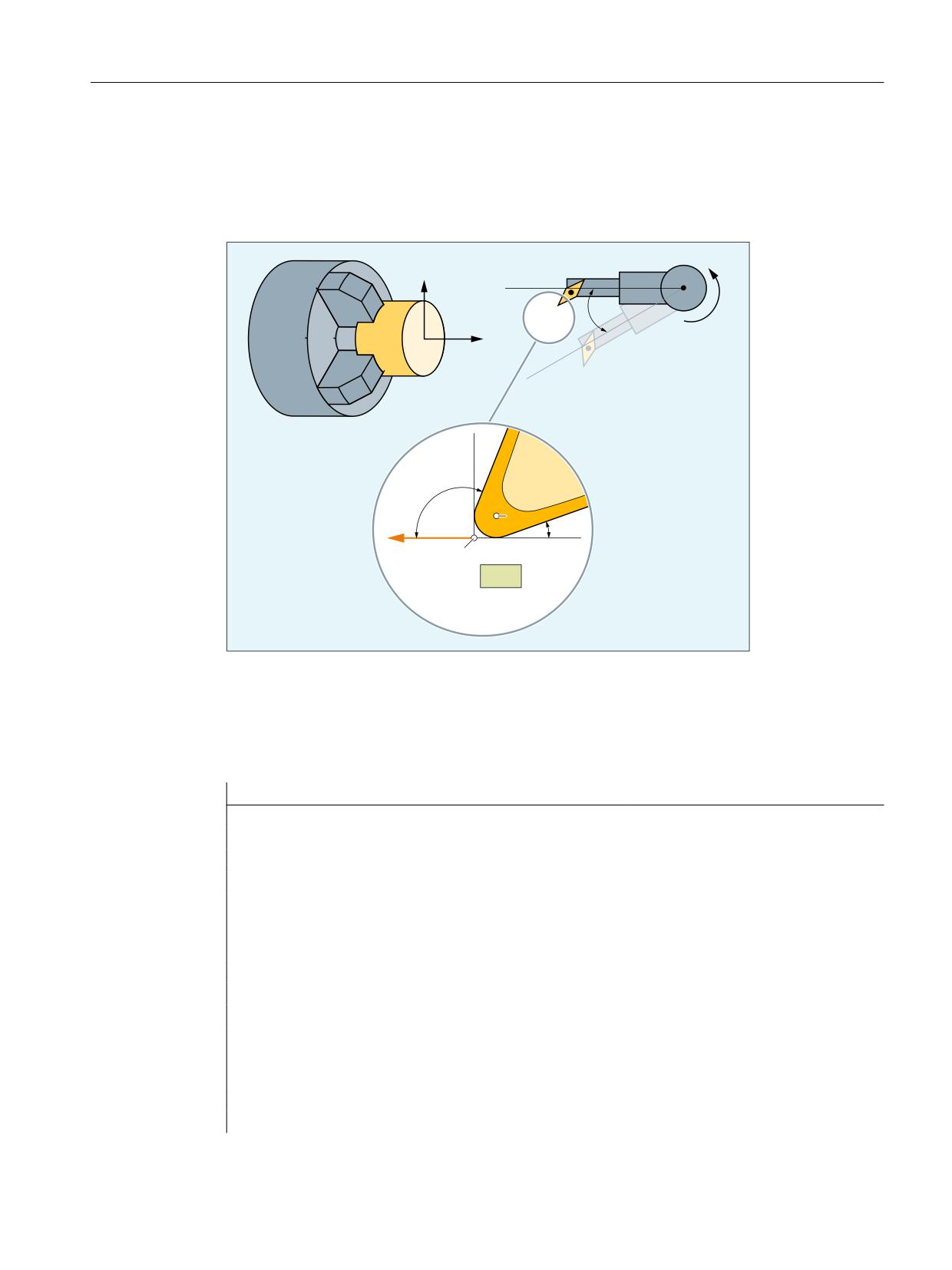
Tool offsets
11.11 Modification of the offset data for rotatable tools
Effectiveness of the modified cutting data
The modified cutting edge position and the modified cutting edge reference point are
immediately effective when programming, even for a tool that is already active. A tool does
not have to be re-selected for this purpose.
;
%
r
=
r
6
r
3
6/
S:
Cutting edge center point
P:
Cutting edge reference point
SL:
Cutting edge position
Figure 11-4
Tool with cutting edge position 3 and an orientable tool carrier that can rotate the tool
around the B axis.
Program code
Comment
N10 $TC_DP1[1,1]=500
N20 $TC_DP2[1,1]=3
;Cutting edge position
N30 $TC_DP3[1,1]=12
N40 $TC_DP4[1,1]=1
N50 $TC_DP6[1,1]=6
N60 $TC_DP10[1,1]=110
; Holder angle
N70 $TC_DP11[1,1]=3
; Cut direction
N80 $TC_DP24[1,1]=25
; Clearance angle
N90 $TC_CARR7[2]=0 $TC_CARR8[2]=1 $TC_CARR9[2]=0
; B axis
N100 $TC_CARR10[2]=0 $TC_CARR11[2]=0
; C axis
$TC_CARR12[2]=1
N110 $TC_CARR13[2]=0
N120 $TC_CARR14[2]=0
N130 $TC_CARR21[2]=X
Job Planning
Programming Manual, 12/2018, A5E40869460B AB
465
Tool offsets
11.11 Modification of the offset data for rotatable tools
Program code
Comment
N140 $TC_CARR22[2]=X
N150 $TC_CARR23[2]="M"
N160 TCOABS CUTMOD=0
N170 G18 T1 D1 TCARR=2
; X
Y
Z
N180 X0 Y0 Z0 F10000
; 12.000
0.000
1.000
N190 $TC_CARR13[2]=30
N200 TCARR=2
N210 X0 Y0 Z0
; 10.892
0.000
-5.134
N220 G42 Z-10
;
8.696
0.000
-17.330
N230 Z-20
;
8.696
0.000
-21.330
N240 X10
; 12.696
0.000
-21.330
N250 G40 X20 Z0
; 30.892
0.000
-5.134
N260 CUTMOD=2 X0 Y0 Z0
;
8.696
0.000
-7.330
N270 G42 Z-10
;
8.696
0.000
-17.330
N280 Z-20
;
8.696
0.000
-21.330
N290 X10
; 12.696
0.000
-21.330
N300 G40 X20 Z0
; 28.696
0.000
-7.330
N310 M30
The numerical values in the comments specify the end of block positions in the machine coordinates
(MCS) in the sequence X → Y → Z.
Explanations
In block N180, initially the tool is selected for CUTMOD=0 and non-rotated tool holders that can
be orientated. As all offset vectors of the tool holder that can be orientated are 0, the position
that corresponds to the tool lengths specified in $TC_DP3[1,1] and $TC_DP4[1,1] is
approached.
The tool holder that can be orientated with a rotation of 30° around the B axis is activated in
block N200. As the cutting edge position is not modified due to CUTMOD=0, the old cutting edge
reference point is decisive just as before. This is the reason why in block N210 the position is
approached, which keeps the old tool nose reference point at the zero (i.e. the vector (1, 12)
is rotated through 30° in the Z/X plane).
In block N260, contrary to block N200, CUTMOD=2 is effective. As a result of the tool holder
rotation that can be orientated, the modified cutting edge position becomes 8. Deviating axis
positions also result from this.
The tool radius compensation (TRC) is activated in blocks N220 and/or N270. The different
cutting edge position in both program sections has no effect on the end positions of the blocks
in which the TRC is active; the corresponding positions are therefore identical. The different
cutting edge positions only become effective again in the deselect blocks N260 and/or N300.
Job Planning
466
Programming Manual, 12/2018, A5E40869460B AB
Tool offsets
11.12 Working with tool environments
11.12
Working with tool environments
Overview of functions
● Save tool environment (TOOLENV) (Page 467)
● Delete tool environment (DELTOOLENV) (Page 470)
● Read T, D and DL number (GETTENV) (Page 471)
● Read tool lengths and/or tool length components (GETTCOR) (Page 472)
● Change tool components (SETTCOR) (Page 478)
System variables overview
● Read information about the saved tool environments ($P_TOOLENVN, ($P_TOOLENV)
(Page 472)
11.12.1
Save tool environment (TOOLENV)
The TOOLENV function is used to save any current states needed for the evaluation of tool
data stored in the memory.
The individual data are as follows:
● The active G command of group:
-
6 (G17, G18, G19)
-
56 (TOWSTD, TOWMCS, TOWWCS, TOWBCS, TOWTCS, TOWKCS)
● The active transverse axis
● Machine data:
- MD18112 $MN_MM_KIND_OF_SUMCORR (properties of the summed offsets in the
TO area)
- MD20360 $MC_TOOL_PARAMETER_DEF_MASK (definition of tool parameters).
Job Planning
Programming Manual, 12/2018, A5E40869460B AB
467
Tool offsets
11.12 Working with tool environments
● Setting data:
- SD42900 $SC_MIRROR_TOOL_LENGTH (sign change tool length when mirroring)
- SD42910 $SC_MIRROR_TOOL_WEAR (sign change tool wear when mirroring)
- SD42920 $SC_WEAR_SIGN_CUTPOS (sign of the tool wear with cutting edge systems)
- SD42930 $SC_WEAR_SIGN (sign of wear)
- SD42935 $SC_WEAR_TRANSFORM (transformations for tool components)
- SD42940 $SC_LENGTH_CONST (change of the tool length components for a plane
change)
- SD42942 $SC_TOOL_LENGTH_CONST_T (change of tool length components for
turning tools at change of plane)
- SD42950 $SC_TOOL_LENGTH_TYPE (allocation of the tool length components
independent of tool type)
- SD42954 $SC_TOOL_ORI_CONST_M (change of tool orientation components for
milling tools at change of plane)
- SD42956 $SC_TOOL_ORI_CONST_T (change of tool orientation components for
turning tools at change of plane)
● The orientation component of the current complete frame (rotation and mirroring, no work
offsets or scaling)
● The orientation component and the resulting length of the active toolholder with orientation
capability
● The orientation component and the resulting length of an active transformation
In addition to the data describing the environment of the tool, the T number, D number and DL
number of the active tool are also stored, so that the tool can be accessed later in the same
environment as the TOOLENV call, without having to name the tool again.
Syntax
<Status> = TOOLENV(<name>)
Meaning
TOOLENV(...):
Predefined function to save a tool environment
Alone in the
Yes
block:
Job Planning
468
Programming Manual, 12/2018, A5E40869460B AB
Tool offsets
11.12 Working with tool environments
<Status>:
Function return value. Negative values indicate error states.
Data type:
INT
Value:
0
Function OK
-1
No memory reserved for tool environments:
MD18116 $MN_MM_NUM_TOOL_ENV = 0
This means that the "tool environments" functionality is not
available.
-2
No more free memory locations for tool environments available.
-3
Null string illegal as name of a tool environment.
-4
No parameter (<name>) specified.
Parameters
1
<name>:
Name, under which the current data set should be saved.
If a data set of the same name already exists, then it is overwritten. In this case,
the status is "0".
Data type:
STRING
Additional information
Base dimension/adapter dimension - tool length compensation
When the tool magazine management is active (only available with the "Tool management"
option!), the value of the following machine data defines whether the adapter length or the tool
base dimension (cutting edge-specific parameters $TC_DP21, $TC_DP22 and $TC_DP23) is
incorporated in the calculation of the tool length:
MD18104 $MN_MM_NUM_TOOL_ADAPTER (tool adapter in TO area).
Since a change to this machine data only takes effect after the control system has powered
up, it is not saved in the tool environment.
Resulting length of toolholders with orientation capability and transformations:
Note
Both toolholders with orientation capability and transformations can use system variables or
machine data, which act as additional tool length components, and which can be subjected
partially or completely to the rotations performed. The resulting additional tool length
components must also be saved when TOOLENV is called, because they represent part of
the environment, in which the tool is used.
Adapter transformation
The adapter transformation is a property of the tool adapter and thus of the complete tool. It
is, therefore, not part of a tool environment, which can be applied to another tool.
By saving the complete data necessary to determine the overall tool length, it is possible to
calculate the effective length of the tool at a later point in time, even if the tool is no longer
active or if the conditions of the environment (e.g. G codes or setting data) have changed.
Similarly, the effective length of a different tool can be calculated assuming that it would be
used under the same conditions as the tool, for which the status was saved.
Job Planning
Programming Manual, 12/2018, A5E40869460B AB
469
Tool offsets
11.12 Working with tool environments
Maximum number of data sets for tool environments
Machine data MD18116 $MN_MM_NUM_TOOL_ENV is used to define the maximum number
of data sets that can be saved to describe the tool environments. The data are in the TOA
area. They are kept even when the control system is switched off.
Data cannot be backed up. This means that this data cannot be transferred between the
different control systems.
11.12.2
Delete tool environment (DELTOOLENV)
The DELTOOLENV function is used to delete the data sets that are used to describe tool
environments. Deletion means that the set of data stored under a particular name can no longer
be accessed (an access attempt triggers an alarm).
Note
Data sets can only be deleted using the DELTOOLENV function, by an INITIAL.INI download
or by a cold start (NC power up with default machine data). There are no additional automatic
deletion operations.
Syntax
<Status> = DELTOOLENV(<name>)
<Status> = DELTOOLENV()
Meaning
DELTOOLENV(...):
Predefined function to delete a tool environment
Alone in the
Yes
block:
<Status>:
Function return value. Negative values indicate error states.
Data type:
INT
Value:
0
Function OK
-1
No memory reserved for tool environments:
MD18116 $MN_MM_NUM_TOOL_ENV = 0
This means that the "tool environments" functionality is not
available.
-2
A tool environment with the specified name does not exist.
Parameters
1
<name>:
Name of data set to be deleted
Data type:
STRING
DELTOOLENV():
DELTOOLENV() deletes data sets describing tool environments without spec-
ifying a name
Job Planning
470
Programming Manual, 12/2018, A5E40869460B AB
Tool offsets
11.12 Working with tool environments
11.12.3
Read T, D and DL number (GETTENV)
The GETTENV function is used to read the T, D and DL numbers stored in a tool environment.
Syntax
<Status> = GETTENV(<name>, <TDDL>)
Meaning
GETTENV(...):
Predefined function to read T, D and DL numbers in a data set to describe a tool
environment
Alone in the
Yes
block:
<Status>:
Function return value. Negative values indicate error states.
Data type:
INT
Value:
0
Function OK
-1
No memory reserved for tool environments:
MD18116 $MN_MM_NUM_TOOL_ENV = 0
This means that the "tool environments" functionality is not
available.
-2
A tool environment with the specified name does not exist.
Parameters
1
<name>:
Name of the data set from which the T, D and DL numbers are to be read
Data type:
STRING
2
<TDDL>:
The field of this result parameter contains the T, D and DL numbers of the tool,
whose tool environment is saved in the specified data set:
● <TDDL> [0]: T number
● <TDDL> [1]: D number
● <TDDL> [2]: DL number
Data type:
INT[3]
GETTENV(,<TDDL>),
When calling function GETTENV, it is permissible to omit the first pa-
GETTENV("",<TDDL>):
rameter - or to transfer the null string as first parameter. In these two
special cases, in <TDDL>, the T, D and DL numbers of theactive tool
are returned.
Job Planning
Programming Manual, 12/2018, A5E40869460B AB
471
Tool offsets
11.12 Working with tool environments
11.12.4
Read information about the saved tool environments ($P_TOOLENVN,
($P_TOOLENV)
Information regarding the saved tool environments can be read using the following system
variables:
$P_TOOLENVN:
Supplies the number of data sets (which have still not been deleted) - defined
using TOOLENV - to describe tool environments
Syntax:
<n> = $P_TOOLENVN
Meaning:
<n>:
Number of defined data sets
Data type:
INT
Value range:
0 ... MD18116
$MN_MM_NUM_TOOL_ENV
This system variable can be accessed even if no tool environments are possible
(MD18116 = 0). In this case, the return value is "0".
$P_TOOLENV:
Supplies the name of the <i>th data set to describe a tool environment
Syntax:
<Name> = $P_TOOLENV[<i>]
Meaning:
<name>:
Name of the data set with number <i>
Data type:
STRING
<i>:
Number of the data set
Data type:
INT
Value range:
1 ... $P_TOOLENVN
The assignment of numbers to data sets is not fixed, but can be changed as a
result of deleting or creating data sets. The data sets are numbered internally.
If <i> refers to a data set that has not been defined, then the null string is returned.
If index <i> is not valid, i.e. <i> is less than 1 or higher than that the maximum
number of data sets for tool environments (MD18116 $MN_MM_NUM_TOO-
LENV), then the following alarm is output:
Alarm 17020 "inadmissible array index 1"
11.12.5
Read tool lengths and/or tool length components (GETTCOR)
The GETTCOR function is used to read out tool lengths or tool length components.
The parameters can be used to specify which components are considered and the conditions
under which the tool is used.
Syntax
<Status> = GETTCOR(<Len>[, <Comp>, <Stat>, <T>, <D>, <DL>])
Meaning
GETTCOR(...):
Predefined function to read tool lengths or to read tool length components
Alone in the
Yes
block:
Job Planning
472
Programming Manual, 12/2018, A5E40869460B AB
Tool offsets
11.12 Working with tool environments
<Status>:
Function return value. Negative values indicate error states.
Data type:
INT
Value:
0
Function OK
-1
No memory reserved for tool environments:
MD18116 $MN_MM_NUM_TOOL_ENV = 0
This means that the "tool environments" functionality is not
available.
-2
A tool environment with the name specified under <Stat> does
not exist.
-3
Invalid string in parameter <Comp>.
Causes of this error can be invalid characters or characters pro-
grammed twice.
-4
Invalid T number
-5
Invalid D number
-6
Invalid DL number
-7
Attempt to access a non-existent memory module.
-8
Attempt to access a non-existent option (programmable tool
orientation, tool management).
-9
The <Comp> string contains a colon (identifier for the specifi-
cation of a coordinate system), but it is not followed by a valid
character denoting the coordinate system.
Parameters
1
<Len>:
Result vector
Data type:
REAL[11]
The vector components are arranged in the following order:
● <Len> [0]: Tool type
● <Len> [1]: Cutting edge position
● <Len> [2]: Abscissa
● <Len> [3]: Ordinate
● <Len> [4]: Applicate
● <Len> [5]: Tool radius
The coordinate system defined in <Comp> and <Stat> is used as the reference
coordinate system for the length components. If a coordinate system is not defined
in <Comp>, then tool lengths are displayed in the machine coordinate system.
The assignment of the abscissa, ordinate and applicate to the geometry axes
depends on the active plane used in the tool environment. This means, for G17,
the abscissa is parallel to X, with G18 it is parallel to Z, etc.
Components <Len>[6] to <Len>[10] contain the additional parameters, which can
be used to specify the geometry description of a tool (e.g. $TC_DP7 to $TC_DP11
for the geometry and the corresponding components for wear or sum and setup
offsets).
These 5 additional elements and the tool radius are only defined for components
E, G, S, and W. Their evaluation does not depend on <Stat>. The corresponding
values in <Len>[6] to <Len>[10] can thus only be not equal to zero if at least one
of the four specified components is involved in the tool length calculation. The
remaining components do not influence the result. The dimensions refer to the
control's basic system (inch or metric).
Job Planning
Programming Manual, 12/2018, A5E40869460B AB
473
Tool offsets
11.12 Working with tool environments
2
<Comp>:
Tool length components (optional)
Data type:
STRING
The character string consists of two substrings, which are separated from one
another by a colon.
General form: "<SubStr_1> [: <SubStr_2]"
<SubStr_1>:
The first substring designates the tool length components to be
taken into account when calculating the tool length.
The order of the characters in the substrings, and their notation
(upper or lower case), is arbitrary. Any number of blanks or
white spaces can be inserted between the characters.
Note:
It is not permissible that the characters in the substring are pro-
grammed twice.
Charac-
-
Minus symbol (only allowed as first character)
ters:
The complete tool length is calculated, minus
the components specified in the next string.
C
Adapter or tool base dimension (whichever of
the two alternative components is active for the
tool in use)
E
Setup offsets
G
Geometry
K
Kinematic transformation (is only evaluated for
generic 3, 4 and 5-axis transformation)
S
Summed offsets
T
Toolholder with orientation capability
W
Wear
If the first substring is empty (except for white spaces), the com-
plete tool length is calculated allowing for all components. This
applies even if the <Comp> parameter is not specified.
<Substr_2>:
The optional second substring identifies the coordinate system,
in which the tool length is to be output.
The second substring only comprises one single relevant char-
acter.
Charac-
A
Adjustable coordinate system (ACS)
ters:
B
Basic coordinate system (BCS)
K
Tool coordinate system of kinematic transfor-
mation (KCS)
M
Machine coordinate system (MCS)
T
Tool coordinate system (TCS)
W
Workpiece coordinate system (WCS)
If no coordinate system is specified, the evaluation is performed
in the MCS (machine coordinate system). If any rotations are
to be taken into account, they are specified in the tool environ-
ment defined in <Stat>.
3
<_Stat>:
Name of the data set for describing a tool environment (optional)
Data type:
STRING
If the value of this parameter is the null string (""), or is not specified, then the
current status is used. The current tool is used if a tool is not specified.
Job Planning
474
Programming Manual, 12/2018, A5E40869460B AB
Tool offsets
11.12 Working with tool environments
4
<T>:
Internal T number of the tool (optional).
Data type:
INT
If this parameter is not specified or if its value is "0", then the tool stored in <Stat>
is used.
If the value of this parameter is "-1", then the T number of the active tool is used.
It is also possible to explicitly specify the number of the active tool.
Note:
If <Stat> is not specified, the actual status is used as the tool environment. Since
<T> = 0 refers to the T number saved in the tool environment, the active tool is
used in this environment, i.e. parameters <T> = 0 and <T> = -1 have the same
meaning in this special case.
5
<D>:
Cutting edge of the tool (optional).
Data type:
INT
If this parameter is not specified, or if its value is "0", then the D number used is
based on the source of the T number. If the T number from the tool environment
is used, then the D number of the tool environment is also read, otherwise the D
number of the currently active tool is read.
6
<DL>:
Number of the offset dependent on the location (optional).
Data type:
INT
If this parameter is not specified, then the DL number used is based on the source
of the T number. If the T number from the tool environment is used, then the D
number of the tool environment is also read, otherwise the D number of the cur-
rently active tool is read.
Examples
GETTCOR(_LEN)
Calculates the tool length of the currently active
tool in the machine coordinate system allowing for
all components.
GETTCOR(_LEN,"CGW:W")
Calculates the tool length for the active tool, con-
sisting of the adapter or tool base dimension, ge-
ometry and wear. Further components, such as
toolholder with orientation capability or kinematic
transformation, are not considered. Output in the
workpiece coordinate system.
GETTCOR (_LEN,"-K:B")
Calculates the complete tool length of the active
tool without allowing for the length components of
a possibly active kinematic transformation. Output
in the basic coordinate system.
GETTCOR (_LEN,":M","Testenv1",,3)
Calculates the complete tool length in the machine
coordinate system for the tool stored in the tool
environment named "Testenv1". However, the cal-
culation is performed for cutting edge number D3,
regardless of the cutting edge number stored.
Job Planning
Programming Manual, 12/2018, A5E40869460B AB
475

Tool offsets
11.12 Working with tool environments
Additional information
Adapter transformation/toolholder with orientation capability/kinematic transformation
Any rotations and component exchanges initiated by the adapter transformation, toolholder
with orientation capability and kinematic transformation, are part of the tool environment. They
are thus always performed, even if the corresponding length component is not supposed to
be included. If this is undesirable, tool environments must be defined, in which the
corresponding transformations are not active. In many cases (i.e. any time a transformation
or toolholder with orientation capability is not used on a machine), the data sets stored for the
tool environments automatically fulfill these conditions, with the result that the user does not
need to make special provision.
Turning and grinding tools: Calculating the tool length depending on MD20360
$MC_TOOL_PARAMETER_DEF_MASK
The following machine data defines how the wear and tool length are to be evaluated if a
diameter axis is used for turning and grinding tools.
MD20360 $MC_TOOL_PARAMETER_DEF_MASK (definition of tool parameters).
Bit
Value
0
For turning and grinding tools, the wear parameter of the transverse axis is taken into account
as the diameter value:
= 0 (default)
No
= 1
Yes
1
For turning and grinding tools, the tool length component of the transverse axis is taken into
account as the diameter value:
= 0 (default)
No
= 1
Yes
If the bits involved are set, the associated entry is weighted with a factor of 0.5. This weighting
is reflected in the tool length returned by GETTCOR.
Example:
MD20360 $MC_TOOL_PARAMETER_DEF_MASK = 3
MD20100 $MC_DIAMETER_AX_DEF (geometry axis with transverse axis function) = "X"
X is diameter axis (standard turning machine configuration)
Program code
Comment
N30 $TC_DP1[1,1]=500
N40 $TC_DP2[1,1]=2
N50 $TC_DP3[1,1]=3.0
; geometry L1
N60 $TC_DP4[1,1]=4.0
N70 $TC_DP5[1,1]=5.0
N80 $TC_DP12[1,1]=12.0
; wear L1
N90 $TC_DP13[1,1]=13.0
N100 $TC_DP14[1,1]=14.0
N110 T1 D1 G18
N120 R1=GETTCOR(_LEN,"GW")
N130 R3=_LEN[2]
; 17.0 (= 4.0 + 13.0)
Job Planning
476
Programming Manual, 12/2018, A5E40869460B AB

Tool offsets
11.12 Working with tool environments
Program code
Comment
N140 R4=_LEN[3]
; 7.5 (= 0.5 * 3.0 + 0.5 * 12.0)
N150 R5=_LEN[4]
; 19.0 (= 5.0 + 14.0)
N160 M30
Length components of the kinematic transformation and toolholder with orientation capability
If a toolholder with orientation capability is taken account of during the tool length calculation,
the following vectors are included in that calculation:
Type
Vectors
M
l1 and l2
T
l1, l2 and l3
P
The tool length is not influenced by the toolholder with orientation capability.
In generic 5-axis transformation, the following machine data are included in the tool length
calculation for transformer types 24 and 56:
Transforma-
Machine data
tion type
24
MD24550/24650 $MC_TRAFO5_BASE_TOOL_1/2
MD24560/24660 $MC_TRAFO5_JOINT_OFFSET_1/2
MD24558/24658 $MC_TRAFO5_PART_OFFSET_1/2
56
MD24550/24650 $MC_TRAFO5_BASE_TOOL_1/2
MD24560/24660 $MC_TRAFO5_JOINT_OFFSET_1/2
Transformation type 56 (moving tool and moving workpiece) corresponds to type M for
toolholders with orientation capability.
For this 5-axis transformation, in the previous software releases, vector MD24560/24660
$MC_TRAFO5_JOINT_OFFSET_1/2 (vector of kinematic offset of the 1st/2nd 5-axis
transformation in the channel) corresponds to the sum of the two vectors l1 and l3 for a type
M tool carrier with orientation capability.
Only the sum is relevant for the transformation in both cases. The way, in which the two
individual components are composed, is insignificant. However, when calculating the tool
length, it is relevant which component is assigned to the tool and which is assigned to the tool
table. This is the reason that machine data MD24558/24658
$MC_TRAFO5_JOINT_OFFSET_PART_1/2 (vector kinematic offset in table) was introduced.
It corresponds to vector l3. Machine data:MD24560/24660
$MC_TRAFO5_JOINT_OFFSET_1/2 no longer corresponds to the sum of l1 and l3, but only
to vector l1. If machine data MD24558/24658 $MC_TRAFO5_JOINT_OFFSET_PART_1/2 is
equal to zero, the behavior is the same as before.
Compatibility
The GETTCOR function is used in conjunction with the TOOLENV and SETTCOR functions
to replace parts of the functionality, which were previously implemented externally in the
measuring cycles.
Only some of the parameters, which actually determine the effective tool length, were
implemented in the measuring cycles. The functions mentioned above can be configured to
reproduce the behavior of the measuring cycles in relation to the tool length calculation.
Job Planning
Programming Manual, 12/2018, A5E40869460B AB
477
Tool offsets
11.12 Working with tool environments
11.12.6
Change tool components (SETTCOR)
The SETTCOR function is used to change tool components taking into account all general
conditions that can be involved when evaluating the individual components.
Note
Regarding the terminology: If in the following, in conjunction with the tool length, tool
components are involved, then the components considered from a vectorial perspective are
meant, which make up the complete tool length (e.g. geometry or wear). Such a component
comprises three individual values (L1, L2, L3), which are called coordinate values in the
following.
The tool component "geometry" therefore comprises three coordinate values $TC_DP3 to
$TC_DP5.
Syntax
<Status> = SETTCOR(<CorVal>, <Comp>, [<CorComp>, <CorMode>, <GeoAx>,
<Stat>, <T>, <D>, <DL>])
Meaning
SETTCOR(...):
Predefined function to change tool components
Alone in the
Yes
block:
Job Planning
478
Programming Manual, 12/2018, A5E40869460B AB
Tool offsets
11.12 Working with tool environments
<Status>:
Function return value. Negative values indicate error states.
Data type:
INT
Value:
0
Function OK
-1
No memory reserved for tool environments:
MD18116 $MN_MM_NUM_TOOL_ENV = 0
This means that the "tool environments" functionality is not
available.
-2
A tool environment with the name specified under <Stat> does
not exist.
-3
Invalid string in parameter <Comp>.
Causes of this error can be invalid characters or characters pro-
grammed twice.
-4
Invalid T number.
-5
Invalid D number.
-6
Invalid DL number.
-7
Attempt to access a non-existent memory module.
-8
Attempt to access a non-existent option (programmable tool
orientation, tool management).
-9
Illegal numerical value for parameter <CorComp>.
-10
Illegal numerical value for parameter <CorMode>.
-11
The contents of parameters <Comp> and <CorComp> are con-
tradictory.
-12
The contents of parameters <Comp> and <CorMode> are con-
tradictory.
-13
The content of the <GeoAx parameter does not designate a
geometry axis.
-14
Write attempt to a non-existent setup offset.
Parameters
1
<CorVal>:
Correction vector
In the workpiece coordinate system (WCS) defined by <Stat>, the following as-
signment applies:
● <CorVal> [0]: Abscissa
● <CorVal> [1]: Ordinate
● <CorVal> [2]: Applicate
If only one tool component is to be corrected (i.e. no vectorial correction, see
parameter <CorMode>), the correction value is always in <CorVal>[0], independ-
ent of the axis on which it acts. The contents of the other two components are then
not evaluated.
If <CorVal> or a component of <CorVal> refers to the transverse axis, then the
data is evaluated as radius dimension. This means that a tool is, for example,
"longer" by the specified dimension; this correspondingly results in a change to
the workpiece diameter that is twice as large.
The dimensions refer to the basic system (inch or metric) of the control system.
Data type:
REAL[3]
Job Planning
Programming Manual, 12/2018, A5E40869460B AB
479
Tool offsets
11.12 Working with tool environments
2
<Comp>:
Tool component(s)
Data type:
STRING
The character string consists of two substrings, which are separated from one
another by a colon.
General form: "<SubStr_1> [: <SubStr_2]"
<SubStr_1>:
The first substring must always be available, and can either
comprise one or two characters. The first or only character for
the 1st component (Val1) and the second character for the 2nd
component (Val2), which are processed according to the sub-
sequent parameters <CorComp> and <CorMode>.
Charac-
C
Adapter or tool base dimension (whichever
ters:
of the two alternative components is active
for the tool in use)
E
Setup offsets
G
Geometry
S
Sum offsets
W
Wear
<Substr_2>:
The second substring is optional. Alternatively, it can comprise
(individual) letters "W" or "T".
Charac-
W
If the second substring is empty or contains
ters:
the letter "W", then the offset values are
taken into account as if they had been
measured in the workpiececoordinate sys-
tem (WCS).
T
If the second substring contains the letter
"T", then the offset values are taken into
account as if they had been measured in
the toolcoordinate system (Tool Coordinate
System, TCS).
The notation of the characters in the string (upper or lower case) is arbitrary. Any
number of spaces or tabs (white spaces) can be inserted.
Job Planning
480
Programming Manual, 12/2018, A5E40869460B AB

Tool offsets
11.12 Working with tool environments
3
<CorComp>:
Specifies the component(s) of the tool data sets that are to be described (optional).
Data type:
INT
Value:
0
Offset value <CorVal>[0] refers to the geometry axis transferred
in parameter <GeoAx> in the workpiece coordinate system - or
in the tool coordinate system (also see a description of param-
eter <Comp>). This means that the offset value must be calcu-
lated in the designated tool components so that, taking account
all the parameters that can influence the tool length calculation,
a change of the total tool length by the specified value in the
specified axis direction is obtained.
This change should be achieved by correcting the component
specified in <Comp> and the symbolic algorithm specified in
<CorMode> (see the following parameters). The resulting cor-
rection can therefore have an effect on all three axis compo-
nents.
1
Like "0", however, vectorial. The content of vector <CorVal>
refers to abscissa, ordinate and applicate in the workpiece co-
ordinate system or tool coordinate system (see the description
of parameter <Comp>).
Subsequent parameter <GeoAx> is not evaluated.
2
Vectorial offset, i.e. L1, L2 and L3 can change simultaneously.
In contrast to the versions from "0 and "1", the offset values
contained in <CorVal> refer to the coordinates of Val1 compo-
nents (see following parameter <CorMode>) of the tool.
Any possible inclination of an existing tool compared with the
workpiece coordinate system has no influence on the offset.
3 - 5
Correction of tool lengths L1 to L3 ($TC_DP3 to $TC_DP5) or
the corresponding values for wear, setting up or additive offsets.
The offset value is contained in <CorVal>[0]. It is measured in
the coordinates of the Val1 component (see following parameter
<CorMode>) of the tool. Any possible inclination of an existing
tool compared with the workpiece coordinate system has no
influence on the offset.
6
Correction of the tool radius ($TC_DP6) or the corresponding
values for wear, setting up or additive offsets. Bits 10 and 11
(evaluation of the diameter and/or diameter wear data, either
specified as a radius or diameter) in machine data
MD20360 $MC_TOOL_PARAMETER_DEF_MASK are taken
into account.
7 -
Correction of $TC_DP7 to $TC_DP11 or the corresponding val-
11
ues for wear, setting up or additive offsets. These parameters
are treated just like the tool radius.
If this parameter is not specified then its value is "0".
Job Planning
Programming Manual, 12/2018, A5E40869460B AB
481
Tool offsets
11.12 Working with tool environments
4
<CorMode>:
Specifies the type of write operation to be executed (optional).
Data type:
INT
Value:
0
Val1new = <CorVal>
1
Val1new = Val1old + <CorVal>
2
Val1new = <CorVal>
Val2new = 0
3
Val1new = Val1old + Val2old + <CorVal>
Val2new = 0
The notation Val1old + Val2old is symbolic. If the two components (due to the status
of <_Stat>) are evaluated in different ways, i.e. if a rotation is effective between
the two components, then Val2old is transformed prior to addition so that the result-
ing tool length after deleting Val2new and prior to the addition of <CorVal> remains
unchanged.
<CorVal> always refers to Val1. <CorVal> is a value, which dependent on the
second part of parameter <Comp>, is measured in the workpiece coordinate sys-
tem (WCS) or in the tool coordinate system (TCS). It is therefore already trans-
formed with respect to the tool components, in which it should be calculated.
Therefore, it cannot be directly calculated together with the saved value, but must
be transformed back prior to adding to Val1 or Val2. This can mean that the offset
acts on an axis different than the one defined by <CorComp> - or that it acts on
several axes.
For the case <CorComp> = 0, i.e. when <CorVal> does not contain a vector, but
only an individual value, then the described operations are executed in the coor-
dinates in which <CorVal> was measured (WCS/TCS). In particular, this also ap-
plies to setting Val2new to zero in variants 2 and 3. This result is then transformed
back into the coordinates of the tool. This can mean that none of the coordinate
values to be set to zero (L1, L2, L3) become zero, or coordinate values, that were
previously zero, are now not equal to zero. However, if the corresponding opera-
tions are successively executed for all three geometry axes, then it is guaranteed
that all three coordinate values of the components to be deleted are zero. If the
tool is not rotated with respect to the workpiece coordinate system or is rotated
so that all tool components remain parallel to the coordinate axes (axis exchange
operations), then this also ensures that only one tool coordinate changes.
The successive execution of the same operation (<CorMode>) with <Cor-
Comp> = 0 for all three coordinate axes in any sequence is identical with the single
execution of the same operation with <CorComp>=1.
For parameter values "0" and "1", parameter <Comp> must contain one character,
and for parameter values "2" and "3", two characters.
Example:
<Comp> contains string "ES", <CorMode> the value "2"
⇒ Setup offsetnew = <CorVal>, summed offsetnew = 0
If parameter <CorMode> is not specified, then its value is "0".
5
<GeoAx>:
Specifies the index of the geometry axis in which the offset value <CorVal>[0] was
read (optional)
Data type:
INT
Value range:
0 ... 2
Indices 0 to 2 refer to abscissa, ordinate and applicate in the active plane (G17/
G18/G19) of the current tool environment.
The content of this parameter is only evaluated if parameter <CorComp> has a
value of "0".
Job Planning
482
Programming Manual, 12/2018, A5E40869460B AB
Tool offsets
11.12 Working with tool environments
6
<Stat>:
Name of the data set for describing a tool environment (optional)
Data type:
STRING
If the value of this parameter is the null string (""), or is not specified, then the
current status is used. The current tool is used if a tool is not specified.
7
<T>:
Internal T number of the tool (optional).
Data type:
INT
If this parameter is not specified or if its value is "0", then the tool stored in <Stat>
is used.
If the value of this parameter is "-1", then the T number of the active tool is used.
It is also possible to explicitly specify the number of the active tool.
Note:
If <Stat> is not specified, the actual status is used as the tool environment. Since
<T> = 0 refers to the T number saved in the tool environment, the active tool is
used in this environment, i.e. parameters <T> = 0 and <T> = -1 have the same
meaning in this special case.
8
<D>:
Cutting edge of the tool (optional).
Data type:
INT
If this parameter is not specified, or if its value is "0", then the D number used is
based on the source of the T number. If the T number from the tool environment
is used, the D number of the tool environment is also read, otherwise the D number
of the currently active tool is read.
9
<TL>:
Number of the offset dependent on the location (optional).
Data type:
INT
If this parameter is not specified, then the DL number used is based on the source
of the T number. If the T number from the tool environment is used, the D number
of the tool environment is also read, otherwise the D number of the currently active
tool is read. If T, D and DL specify a tool without location-dependent offsets, no
summed or setup offsets may be specified in parameter <Comp> (error code in
<Status>).
Note
Not all possible combinations of the three parameters <Comp>, <CorComp> and <CorMode>
make sense. For example, algorithm 3 in <CorComp> requires that two characters are
specified in <Comp>. If an invalid parameter combination is specified, then a corresponding
error code is returned in the <Status>.
Examples
Example 1
Program code
Comment
N10 DEF REAL _CORVAL[3]
N20 $TC_DP1[1,1]=120
; Milling tool
N30 $TC_DP3[1,1]=10.0
; Geometry L1
N40 $TC_DP12[1,1]=1.0
; wear L1
N50 _CORVAL[0]=0.333
N60 T1 D1 G17 G0
Job Planning
Programming Manual, 12/2018, A5E40869460B AB
483
Tool offsets
11.12 Working with tool environments
Program code
Comment
N70 R1=SETTCOR(_CORVAL,"G",0,0,2)
N80 T1 D1 X0 Y0 Z0
; ==> MCS position X0.000 Y0.000 Z1.333
N90 M30
<CorComp> is "0", therefore, the coordinate value of the geometry component acting in the Z
direction must be replaced by the offset value 0.333.
The resulting total tool length is thus: L1 = 0.333 + 1.000 = 1.333
Example 2
Program code
Comment
N10 DEF REAL _CORVAL[3]
N20 $TC_DP1[1,1]=120
; milling tool
N30 $TC_DP3[1,1]=10.0
; geometry L1
N40 $TC_DP12[1,1]=1.0
; wear L1
N50 _CORVAL[0]=0.333
N60 T1 D1 G17 G0
N70 R1=SETTCOR(_CORVAL,"W",0,1,2)
N80 T1 D1 X0 Y0 Z0
; ==> MCS position X0.000 Y0.000 Z11.333
N90 M30
<CorComp> is "1", this means that the offset value of 0.333 - acting in the Z axis - is added
to the wear value of 1.0.
The resulting total tool length is thus: L1 = 10.0 + 1.333 = 11.333
Example 3
Program code
Comment
N10 DEF REAL _CORVAL[3]
N20 $TC_DP1[1,1]=120
; Milling tool
N30 $TC_DP3[1,1]=10.0
; Geometry L1
N40 $TC_DP12[1,1]=1.0
; Wear L1
N50 _CORVAL[0]=0.333
N60 T1 D1 G17 G0
N70 R1=SETTCOR(_CORVAL,"GW",0,2,2)
N80 T1 D1 X0 Y0 Z0
; ==> MCS position X0.000 Y0.000 Z0.333
N90 M30
<CorComp> is "2", therefore, the offset effective in the Z axis is entered in the geometry
component (the old value is overwritten) and the wear value is deleted.
The resulting total tool length is thus: L1 = 0.333 + 0.0 = 0.333
Example 4
Program code
Comment
N10 DEF REAL _CORVAL[3]
N20 $TC_DP1[1,1]=120
; Milling tool
N30 $TC_DP3[1,1]=10.0
; Geometry L1
Job Planning
484
Programming Manual, 12/2018, A5E40869460B AB
Tool offsets
11.12 Working with tool environments
Program code
Comment
N40 $TC_DP12[1,1]=1.0
; wear L1
N50 _CORVAL[0]=0.333
N60 T1 D1 G17 G0
N70 R1=SETTCOR(_CORVAL,"GW",0,3,2)
N80 T1 D1 X0 Y0 Z0
; ==> MCS position X0.000 Y0.000 Z11.333
N90 M30
<CorComp> is "3", therefore, the wear value and compensation value are added to the
geometry component and the wear component is deleted.
The resulting total tool length is thus: L1 = 11.333 + 0.0 = 11.333
Example 5
Program code
Comment
N10 DEF REAL _CORVAL[3]
N20 $TC_DP1[1,1]=120
; Milling tool
N30 $TC_DP3[1,1]=10.0
; Geometry L1
N40 $TC_DP12[1,1]=1.0
; Wear L1
N50 _CORVAL[0]=0.333
N60 T1 D1 G17 G0
N70 R1=SETTCOR(_CORVAL,"GW",0,3,0)
N80 T1 D1 X0 Y0 Z0
; ==> MCS position X0.333 Y0.000 Z11.000
N90 M30
<CorComp> is "3", as in the previous example, but the compensation is now effective on the
geometry axis with index "0" (X axis), which for a milling tool, is assigned to tool component
L3 due to G17. As a consequence, when calling SETTCOR, tool parameters $TC_DP3 and
$TC_DP12 are not influenced. Instead, the compensation value is entered in $TC_DP5.
Example 6
Program code
Comment
N10 DEF REAL _CORVAL[3]
N20 $TC_DP1[1,1]=500
; turning tool
N30 $TC_DP3[1,1]=10.0
; geometry L1
N40 $TC_DP4[1,1]=15.0
; geometry L2
N50 $TC_DP12[1,1]=10.0
; wear L1
N60 $TC_DP13[1,1]=0.0
; wear L2
N70 _CORVAL[0]=5.0
N80 ROT Y-30
N90 T1 D1 G18 G0
N100 R1=SETTCOR(_CORVAL,"GW",0,3,1)
N110 T1 D1 X0 Y0 Z0
; ==> MCS position X24.330 Y0.000 Z17.500
N120 M30
The tool is a turning tool. A frame rotation is activated in N80, causing the basic coordinate
system (BCS) to be rotated in relation to the workpiece coordinate system (WCS). In the WCS,
the compensation value (N70) acts on the geometry axis with index 1, i.e. on the X axis because
Job Planning
Programming Manual, 12/2018, A5E40869460B AB
485
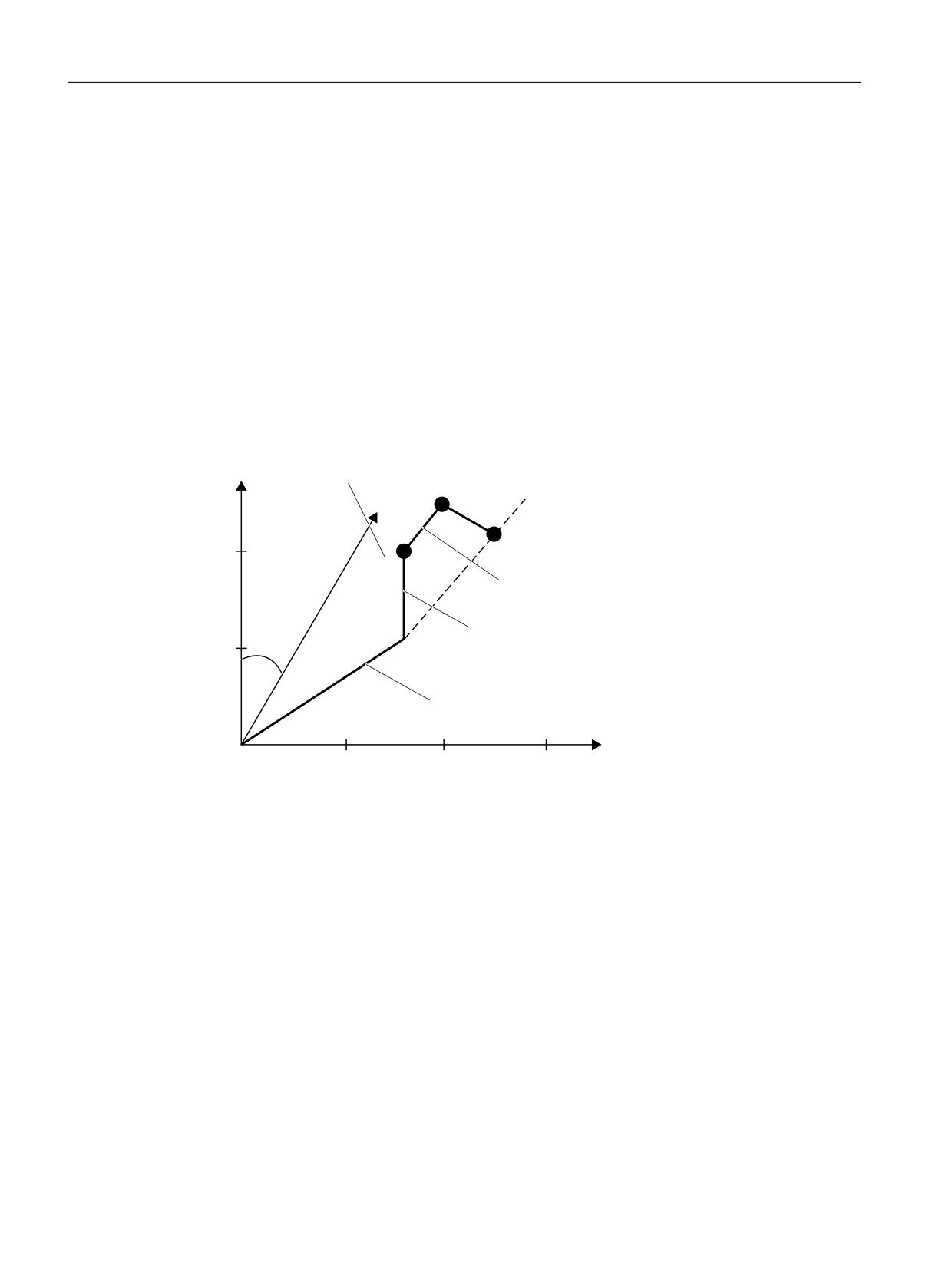
Tool offsets
11.12 Working with tool environments
G18 is active. Since <CorMode> = 3, the tool wear in the direction of the X axis of the WCS
must become zero once N100 has been executed.
The contents of the relevant tool parameters at the end of the program are thus:
$TC_DP3[1,1]: 21.830 ; geometry L1
$TC_DP4[1,1] : 21.830 ; geometry L2
$TC_DP12[1,1] : 2.500 ; wear L1
$TC_DP13[1,1] : -4.330 ; wear L2
The geometrical relationships are shown in the figure below: The total wear including
_CORVAL is mapped onto the X' direction in the WCS. This produces point P2. The
coordinates of this point (measured in X/Y coordinates) are entered in the geometry component
of the tool. The difference vector P2 - P1 remains in the wear. The wear thus no longer has a
component in the direction of _CORVAL.
2ULJLQDO WRRO OHQJWK
[
[
3
B&259$/ DFWLYH LQ WKH ; GLUHFWLRQ
:HDU /
/
*HRPHWU\ /
/
]
If the program example is continued after N110 with the following instructions, then the
remaining wear is included completely in the geometry because the compensation is now
effective in the Z' axis (parameter <GeoAx> = 0):
N120 _CORVAL[0]=0.0
N130 R1=SETTCOR(_CORVAL,"GW",0,3,0)
N140 T1 D1 X0 Y0 Z0 ; ==> MCS position X24.330 Y0.000 Z17.500
Since the new compensation value is "0", the total tool length and thus the position approached
in N140 may not change. If _CORVAL were not equal to "0" in N120, a new total tool length
and thus a new position in N140 would result, however, the wear component of the tool length
would always be zero, i.e. the total tool length is subsequently always contained in the
geometry component of the tool.
Job Planning
486
Programming Manual, 12/2018, A5E40869460B AB
Tool offsets
11.12 Working with tool environments
The same result as that achieved by calling the SETTCOR function with the <CorComp> = 0
parameter twice can also be reached by calling <CorComp> = 1 (vectorial compensation) just
once:
Program code
Comment
N10 DEF REAL _CORVAL[3]
N20 $TC_DP1[1,1]=500
; turning tool
N30 $TC_DP3[1,1]=10.0
; geometry L1
N40 $TC_DP4[1,1]=15.0
; geometry L2
N50 $TC_DP12[1,1]=10.0
; wear L1
N60 $TC_DP13[1,1]=0.0
; wear L2
N70 _CORVAL[0]=0.0
N71 _CORVAL[1]=5.0
N72 _CORVAL[2]=0.0
N80 ROT Y-30
N90 T1 D1 G18 G0
N100 R1=SETTCOR(_CORVAL,"GW",1,3,1)
N110 T1 D1 X0 Y0 Z0
; ==> MCS position X24.330 Y0.000 Z17.500
N120 M30
In this case, all wear components of the tool are set to zero immediately after the first call of
SETTCOR in N100.
Example 7
Program code
Comment
N10 DEF REAL _CORVAL[3]
N20 $TC_DP1[1,1]=500
; turning tool
N30 $TC_DP3[1,1]=10.0
; geometry L1
N40 $TC_DP4[1,1]=15.0
; geometry L2
N50 $TC_DP12[1,1]=10.0
; wear L1
N60 $TC_DP13[1,1]=0.0
; wear L2
N70 _CORVAL[0]=5.0
N80 ROT Y-30
N90 T1 D1 G18 G0
N100 R1=SETTCOR(_CORVAL,"GW",3,3)
N110 T1 D1 X0 Y0 Z0
; ==> MCS position X25.000 Y0.000 Z15.000
N120 M30
When compared to example 6, parameter <CorComp> = 3, and so the <GeoAx> parameter
can be omitted. The value contained in _CORVAL[0] now acts immediately on the tool length
component L1, the rotation in N80 has no effect on the result, the wear components in
$TC_DP12 are included in the geometry component together with _CORVAL[0], with the result
that the total tool length is stored in the geometry component of the tool, due to $TC_DP13,
after the first SETTCOR call in N100.
Job Planning
Programming Manual, 12/2018, A5E40869460B AB
487
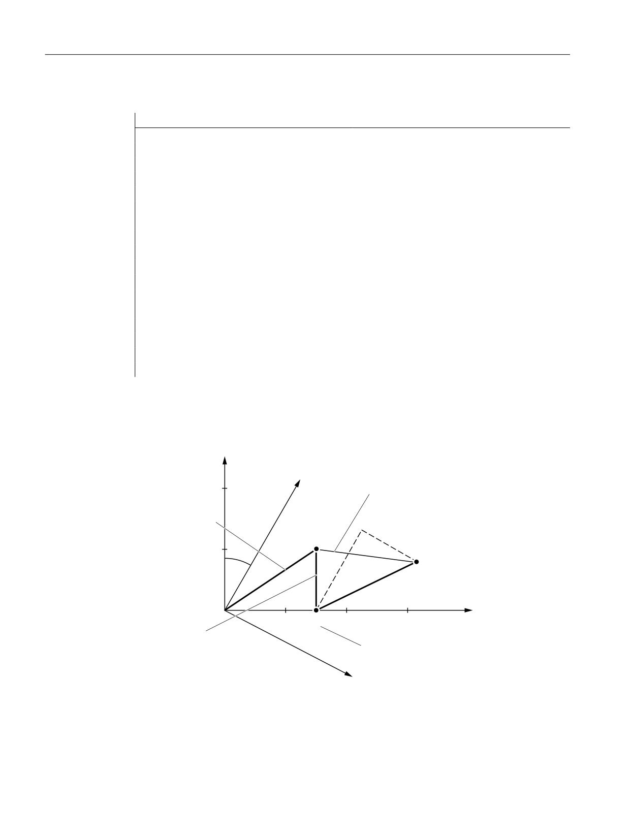
Tool offsets
11.12 Working with tool environments
Example 8
Program code
Comment
N10 DEF REAL _CORVAL[3]
N20 $TC_DP1[1,1]=500
; turning tool
N30 $TC_DP3[1,1]=10.0
; geometry L1
N40 $TC_DP4[1,1]=15.0
; geometry L2
N50 $TC_DP5[1,1]=20.0
; geometry L3
N60 $TC_DP12[1,1]=10.0
; wear L1
N70 $TC_DP13[1,1]=0.0
; wear L2
N80 $TC_DP14[1,1]=0.0
; wear L3
N90 $SC_WEAR_SIGN=TRUE
N100 _CORVAL[0]=10.0
N110 _CORVAL[1]=15.0
N120 _CORVAL[2]=5.0
N130 ROT Y-30
N140 T1 D1 G18 G0
N150 R1=SETTCOR(_CORVAL,"W",1,1)
N160 T1 D1 X0 Y0 Z0
; ==> MCS position X7.990 Y25.000 Z31.160
N170 M30
Setting data:SD42930 $SC_WEAR_SIGN is enabled in N90, i.e. the wear must be evaluated
with a negative sign. The compensation is vectorial (<CorComp> = 1), and the compensation
vector must be added to the wear (<CorMode> = 1). The geometrical relationships in the Z/X
plane are shown in the diagram below:
;
;
5HVXOWLQJ ZHDU FRPSRQHQW
*HRPHWU\
/
/
3
3
B&259$/ <
;
=
3
=
:HDU /
/
2ULJLQDO WRRO OHQJWK
QHJDWLYH HYDOXDWLRQ
=
The geometry component of the tool remains unchanged due to <CorMode> = 1. The
compensation vector defined in the WCS (rotation around the y axis) must be included in the
wear component such that the total tool length in Fig. 3 refers to point P2. Therefore, the
resulting wear component of the tool is given by the distance of the two points P1 and P2.
Job Planning
488
Programming Manual, 12/2018, A5E40869460B AB