SINUMERIK 840D sl/828D. Job Planning. Programming Manual (2010-2018) - page 6

Transformations
7.5 Orientations relative to the path
N... TILT=
Angle for the programmed orientation in the plane,
vertical to the path tangent relative to the surface
normal vector
N... THETA=
Angle of rotation relative to the change of orientation
in the tool direction of the third rotary axis
The values of the angles at the end of block are programmed using LEAD=value,
TILT=value or THETA=value. In addition to the constant angles, polynomials can be
programmed for all three angles up to the 5th degree.
N... PO[PHI]=(a2, a3, a4, a5)
Polynomial for the leading angle LEAD
Polynomial for the tilt angle TILT
N... PO[PSI]=(b2, b3, b4, b5)
Polynomial for the angle of rotation THE-
N... PO[THT]=(d2, d3, d4, d5)
TA
The higher polynomial coefficients, which are zero, can be omitted when programming.
Example: PO[PHI]=a2 results in a parabola for the LEAD angle.
Meaning
Tool orientation relative to the path
ORIPATH:
Tool orientation in relation to path
ORIPATHS
Tool orientation in relation to path, blips in the orientation characteristic are smoothed
:
LEAD:
Angle relative to the surface normal vector in the plane that is defined by the path tangent
and the surface normal vector
TILT:
Rotation of orientation in the Z direction or rotation about the path tangent
THETA:
Rotation about the tool direction toward Z
PO[PHI]:
Orientation polynomial for the LEAD angle
PO[PSI]:
Orientation polynomial for the TILT angle
PO[THT]:
Orientation polynomial for the THETA angle of rotation
Note
Angle of rotation THETA
A 6-axis transformation is required to rotate a tool with a third rotary axis that acts as an
orientation axis about itself.
7.5.3
Interpolation of the tool rotation relative to the path (ORIROTC, THETA)
Interpolation with rotation vectors
The rotation vector of the tool rotation, programmed with ORIROTC, relative to the path tangent
can also be interpolated with an offset that can be programmed using the THETA angle of
Job Planning
Programming Manual, 12/2018, A5E40869460B AB
351
Transformations
7.5 Orientations relative to the path
rotation. A polynomial can, therefore, be programmed up to the 5th degree for the offset angle
using PO[THT].
Syntax
N... ORIROTC
Initiate the rotation of the tool rela-
tive to the path tangent
N... A3= B3= C3= THETA=value
Define the rotation of the orienta-
tion vector
N... A3= B3= C3= PO[THT]=(c2, c3, c4, c5) Interpolate offset angle with poly-
nomial up to 5th degree
A rotation can also be programmed in a separate block without an orientation change taking
place.
Meaning
Interpolation of the rotation of tool relative to the path in 6-axis transformation
ORIROTC:
Initiate tangential rotation vector relative to path tangent
THETA=value:
Angle of rotation in degrees reached by the end of the block
THETA=θe:
Angle of rotation with end angle Θe of rotation vector
THETA=AC(…):
Non-modal switchover to absolute dimensions
THETA=IC(…):
Non-modal switchover to incremental dimensions
PO[THT]=(c2, c3, c4, c5):
Interpolate offset angle with polynomial of 5th degree
Note
Interpolation of the rotation vector ORIROTC
Initiating rotation of the tool relative to the path tangent in the opposite direction to the tool
orientation, is only possible with a 6-axis transformation.
With active ORIROTC
Rotation vector ORIROTA cannot be programmed. If programming is undertaken, ALARM
14128 "Absolute programming of tool rotation with active ORIROTC" is output.
Orientation direction of the tool for 3-axis to 5-axis transformation
The orientation direction of the tool can be programmed via Euler angles, RPY angles or
direction vectors as with 3-axis to 5-axis transformations. Orientation changes of the tool in
space can also be achieved by programming the large-circle interpolation ORIVECT, linear
interpolation of the orientation axes ORIAXES, all interpolations on the peripheral surface of
a taper ORICONxx, and interpolation in addition to the curve in space with two contact points
of the tool ORICURVE.
G
:
Details of the rotary axis motion
X, Y, Z:
Details of the linear axes
Job Planning
352
Programming Manual, 12/2018, A5E40869460B AB

Transformations
7.5 Orientations relative to the path
ORIAXES:
Linear interpolation of machine or orientation axes
ORIVECT:
Large-circle interpolation (identical to ORIPLANE)
ORIMKS:
Rotation in the machine coordinate system
ORIWKS:
Rotation in the workpiece coordinate system
Description, see the Rotations of the tool orientation section
A= B= C=:
Programming the machine axis position
ORIEULER:
Orientation programming via Euler angle
ORIRPY:
Orientation programming via RPY angle
A2= B2= C2=:
Angle programming of virtual axes
ORIVIRT1:
Orientation programming using virtual orientation axes
ORIVIRT2:
(definition 1), definition according to MD $MC_ORIAX_TURN_TAB_1
(definition 2), definition according to MD $MC_ORIAX_TURN_TAB_2
A3= B3= C3=:
Direction vector programming of direction axis
ORIPLANE:
Interpolation in the plane (large-circle interpolation)
ORICONCW:
Interpolation on the peripheral surface of a taper in the clockwise direc-
tion
ORICONCCW:
Interpolation on the peripheral surface of a taper in the counter-clock-
wise direction
ORICONTO:
Interpolation on the peripheral surface of a taper with tangential transition
A6= B6= C6=:
Programming of a rotary axis of the taper (normalized vector)
NUT=angle
Opening angle of taper in degrees
NUT=+179
Traverse angle less than or equal to 180 degrees
NUT=-181
Traverse angle greater than or equal to 180 degrees
ORICONIO:
Interpolation on the peripheral surface of a taper
A7= B7= C7=:
Intermediate orientation (programming as normalized vector)
ORICURVE
Interpolation of the orientation specifying a movement between two con-
tact points of the tool. In addition to the end points, additional curve
XH YH ZH, e.g. with
polynomials can also be programmed.
polynomials
PO[XH]=(xe, x2, x3,
x4, x5)
Note
If the tool orientation with active ORIAXES is interpolated via the orientation axes, the angle
of rotation is only initiated relative to the path at the end of block.
7.5.4
Smoothing of orientation characteristic (ORIPATHS A8=, B8=, C8=)
Changes of orientation that take place with constant acceleration on the contour can cause
unwanted interruptions to the path motions, particularly at the corner of a contour. The resulting
blip in the orientation characteristic can be smoothed by inserting a separate intermediate
block. If ORIPATHS is active during reorientation, the change in orientation occurs at a
constant acceleration. The tool can be retracted in this phase.
Job Planning
Programming Manual, 12/2018, A5E40869460B AB
353

Transformations
7.5 Orientations relative to the path
Machine manufacturer
Please refer to the machine manufacturer's notes on any predefined machine and setting data
used to activate this function.
Machine data can be used to set how the retracting vector is interpreted:
1. In the TCS, the Z coordinate is defined by the tool direction.
2. In the WCS, the Z coordinate is defined by the active plane.
For further explanations about the "Orientation relative to the path" function , see
References:
Function Manual, Special Functions; Multi-axis Transformations (F2)
Syntax
Further programming details are needed at the corner of the contour for constant tool
orientations relative to the path as a whole. The direction and path length of this motion is
programmed via the vector using the components A8=X, B8=Y C8=Z.
N... ORIPATHS A8=X B8=Y C8=Z
Meaning
ORIPATHS:
Tool orientation relative to the path; blip in orientation characteristic is smoothed
A8= B8= C8=:
Vector components for direction and path length
X, Y, Z:
Retracting movement in tool direction
Note
Programming direction vectors A8, B8, C8
If the length of this vector is exactly zero, no retracting movement is executed.
ORIPATHS
Tool orientation relative to the path is activated using ORIPATHS. The orientation is otherwise
transferred from the start orientation to the end orientation by means of linear large-circle
interpolation.
Job Planning
354
Programming Manual, 12/2018, A5E40869460B AB
Transformations
7.6 Compression of the orientation (COMPON, COMPCURV, COMPCAD, COMPSURF)
7.6
Compression of the orientation (COMPON, COMPCURV,
COMPCAD, COMPSURF)
NC programs, in which orientation transformation (TRAORI) is active and tool orientations are
programmed (no matter what type), can be compressed if kept within specified limits.
Programming
Tool orientation
If orientation transformation (TRAORI) is active, for 5-axis machines, tool orientation can be
programmed in the following way (independent of the kinematics):
● Programming of the direction vectors via:
A3=<...> B3=<...> C3=<...>
● Programming of the Eulerangles or RPY-angles via:
A2=<...> B2=<...> C2=<...>
Rotation of the tool
For 6-axis machines you can program the tool rotation in addition to the tool orientation.
The angle of rotation is programmed with:
THETA=<...>
See " Rotation of tool orientation (Page 346) ".
Note
NC blocks, in which a rotation is also programmed, can only be compressed if the angle of
rotation changes linearly. This means that it is not permissible that a polynomial with
PO[THT]=(...) is programmed for the angle of rotation.
General structure of an NC block that can be compressed
The general structure of an NC block that can be compressed can therefore look like this:
N... X=<...> Y=<...> Z=<...> A3=<...> B3=<...> C3=<...> THETA=<...> F=<...>
or
N... X=<...> Y=<...> Z=<...> A2=<...> B2=<...> C2=<...> THETA=<...> F=<...>
Note
The position values can be entered directly (e.g. X90) or indirectly via parameter settings (e.g.
X=R1*(R2+R3)).
Programming tool orientation using rotary axis positions
Tool orientation can be also specified using rotary axis positions, e.g. with the following
structure:
N... X=<...> Y=<...> Z=<...> A=<...> B=<...> C=<...> THETA=<...> F=<...>
Job Planning
Programming Manual, 12/2018, A5E40869460B AB
355
Transformations
7.6 Compression of the orientation (COMPON, COMPCURV, COMPCAD, COMPSURF)
In this case, compression is executed in two different ways, dependent on whether large radius
circular interpolation is executed. If no large radius circular interpolation takes place, then the
compressed change in orientation is represented in the usual way by axial polynomials for the
rotary axes.
Contour accuracy
Depending on the selected compression mode (MD20482 $MC_COMPRESSOR_MODE)
either the configured axis-specific tolerances (MD33100 $MA_COMPRESS_POS_TOL) or the
following channel-specific tolerances - set using setting data - are effective for the geometry
axes and orientation axes for compression:
SD42475 $SC_COMPRESS_CONTUR_TOL (maximum contour deviation)
SD42476 $SC_COMPRESS_ORI_TOL (maximum angular deviation for tool orientation)
SD42477 $SC_COMPRESS_ORI_ROT_TOL (maximum angular deviation for the angle of
rotation of the tool) (only available on 6-axis machines)
References:
Function Manual Basic Functions; 3 to 5-Axis Transformation (F2),
Section: "Compression of the orientation"
Activation/deactivation
Compressor functions are activated by modal G commands COMPON, COMPCURV, COMPCAD
or COMPSURF.
COMPOF terminates the compressor function.
See " NC block compression (COMPON, COMPCURV, COMPCAD) (Page 257) ".
Note
Orientation motion is only compressed when large radius circular interpolation is active (i.e.
tool orientation is changed in the plane which is determined by start and end orientation).
Large radius circular interpolation is executed under the following conditions:
● MD21104 $MC_ORI_IPO_WITH_G_CODE = 0,
ORIWKS is active and
the orientation is programmed as a vector (with A3, B3, C3 or A2, B2, C2).
● MD21104 $MC_ORI_IPO_WITH_G_CODE = 1 and
ORIVECT or ORIPLANE is active.
The tool orientation can be programmed either as a direction vector or with rotary axis
positions. No large radius circle interpolation is performed, if one of the G commands
ORICONxx or ORICURVE is active, or if polynomials for orientation angle (PO[PHI] and
PO[PSI]) are programmed.
Job Planning
356
Programming Manual, 12/2018, A5E40869460B AB
Transformations
7.6 Compression of the orientation (COMPON, COMPCURV, COMPCAD, COMPSURF)
Example
In the example program below, a circle approached by a polygon definition is compressed.
The tool orientation moves on the outside of the taper at the same time. Although the
programmed orientation changes are executed one after the other, but in an unsteady way,
the compressor function generates a smooth motion of the orientation.
Programming
Comment
DEF INT NUMBER=60
DEF REAL RADIUS=20
DEF INT COUNTER
DEF REAL ANGLE
N10 G1 X0 Y0 F5000 G64
$SC_COMPRESS_CONTUR_TOL=0.05
; Maximum deviation of the contour = 0.05 mm
$SC_COMPRESS_ORI_TOL=5
; Maximum deviation of the orientation
= 5 degrees
TRAORI
COMPCURV
; The movement describes a circle generated
from polygons. The orientation moves on a
taper around the Z axis with an opening an-
gle of 45 degrees.
N100 X0 Y0 A3=0 B3=-1 C3=1
N110 FOR COUNTER=0 TO NUMBER
N120 ANGLE=360*COUNTER/NUMBER
N130 X=RADIUS*cos(angle) Y=RADIUS*sin(angle)
A3=sin(angle) B3=-cos(angle) C3=1
N140 ENDFOR
Job Planning
Programming Manual, 12/2018, A5E40869460B AB
357
Transformations
7.7 Activating/deactivating the orientation characteristic (ORISON, ORISOF)
7.7
Activating/deactivating the orientation characteristic (ORISON,
ORISOF)
The "Smoothing of the orientation characteristic" is activated/deactivated in the part program
using the commands of G group 61. The commands are modal.
Preconditions
● System with 5/6-axis transformation.
● Compressor function COMPCAD is active.
Syntax
ORISON
ORISOF
Meaning
ORISON:
Activating the orientation characteristic smoothing
ORISOF:
Deactivating the orientation characteristic smoothing
Example
Program code
Comment
TRAORI()
; Activation of orientation transformation.
COMPCAD
; Activating the COMPCAD compressor function.
ORISON
; Activating orientation smoothing.
$SC_ORISON_TOL=1.0
; Maximum angular deviation of the tool orientation
= 1.0 degrees.
G91
X10 A3=1 B3=0 C3=1
X10 A3=-1 B3=0 C3=1
X10 A3=1 B3=0 C3=1
X10 A3=-1 B3=0 C3=1
X10 A3=1 B3=0 C3=1
X10 A3=-1 B3=0 C3=1
X10 A3=1 B3=0 C3=1
X10 A3=-1 B3=0 C3=1
X10 A3=1 B3=0 C3=1
X10 A3=-1 B3=0 C3=1
ORISOF
; Deactivation of orientation smoothing.
Job Planning
358
Programming Manual, 12/2018, A5E40869460B AB
Transformations
7.7 Activating/deactivating the orientation characteristic (ORISON, ORISOF)
The orientation is pivoted through 90 degrees on the XZ plane from -45 to +45 degrees. Due
to the smoothing of the orientation characteristic the orientation is no longer able to reach the
maximum angle values of -45 or +45 degrees.
Job Planning
Programming Manual, 12/2018, A5E40869460B AB
359

Transformations
7.8 Kinematic transformation
7.8
Kinematic transformation
7.8.1
Activate face end transformation (TRANSMIT)
The front face transformation (TRANSMIT) is activated in the part program or synchronized
action using the TRANSMIT statement.
Syntax
TRANSMIT
TRANSMIT(<n>)
Meaning
TRANSMIT:
Activate TRANSMIT with the first TRANSMIT data set
TRANSMIT(n):
Activate TRANSMIT with the nth TRANSMIT data set
Note
A TRANSMIT transformation active in the channel is activated with:
● Deactivate transformation: TRAFOOF
● Activation of another transformation: E.g. TRACYL, TRAANG, TRAORI
7.8.2
Activate cylinder surface transformation (TRACYL)
The cylinder surface transformation (TRACYL) is activated in the part program or synchronized
action using the TRACYL statement.
Syntax
TRACYL(<d>)
TRACYL(<d>,<n>)
TRACYL(<d>,<n>,<k>)
Meaning
TRACYL(<d>):
Activate TRACYL with the first TRACYL data set and working diameter
<d>
TRACYL (<d>,<n>):
Activate TRACYL with the <n>th TRACYL data set and working diameter
<d>
<d>:
Reference or working diameter
The value must be greater than 1.
Job Planning
360
Programming Manual, 12/2018, A5E40869460B AB

Transformations
7.8 Kinematic transformation
<n>:
TRACYL data set number (optional)
Range of values:
1, 2
<k>:
The parameter <k> is only relevant for transformation type 514
k = 0:
without groove side correction
k = 1:
with groove side correction
If the parameter is not specified, then the parameterized basic position
applies:
$MC_TRACYL_DEFAULT_MODE_<n>
With <n> = TRACYL data set number
Note
A TRACYL transformation active in the channel is switched-off with:
● Deactivate transformation: TRAFOOF
● Activation of another transformation: E.g. TRAANG, TRANSMIT, TRAORI
Example
Program code
Comment
N40 TRACYL(40.)
; Activate TRACYL with the first TRACYL data set
and working diameter 40 mm.
Further information
Program structure
A part program for milling a groove with TRACYL transformation 513 (TRACYL with groove
side offset) generally comprises the following steps:
1. Select tool.
2. Select TRACYL.
3. Select suitable coordinate offset (frame).
4. Positioning.
5. Program OFFN.
6. Select TRC.
7. Approach block (position TRC and approach groove side).
8. Groove center line contour.
9. Deselect TRC.
10.Retraction block (retract TRC and move away from groove side).
11.Positioning.
Job Planning
Programming Manual, 12/2018, A5E40869460B AB
361
Transformations
7.8 Kinematic transformation
12.TRAFOOF.
13.Reselect original coordinate shift (frame).
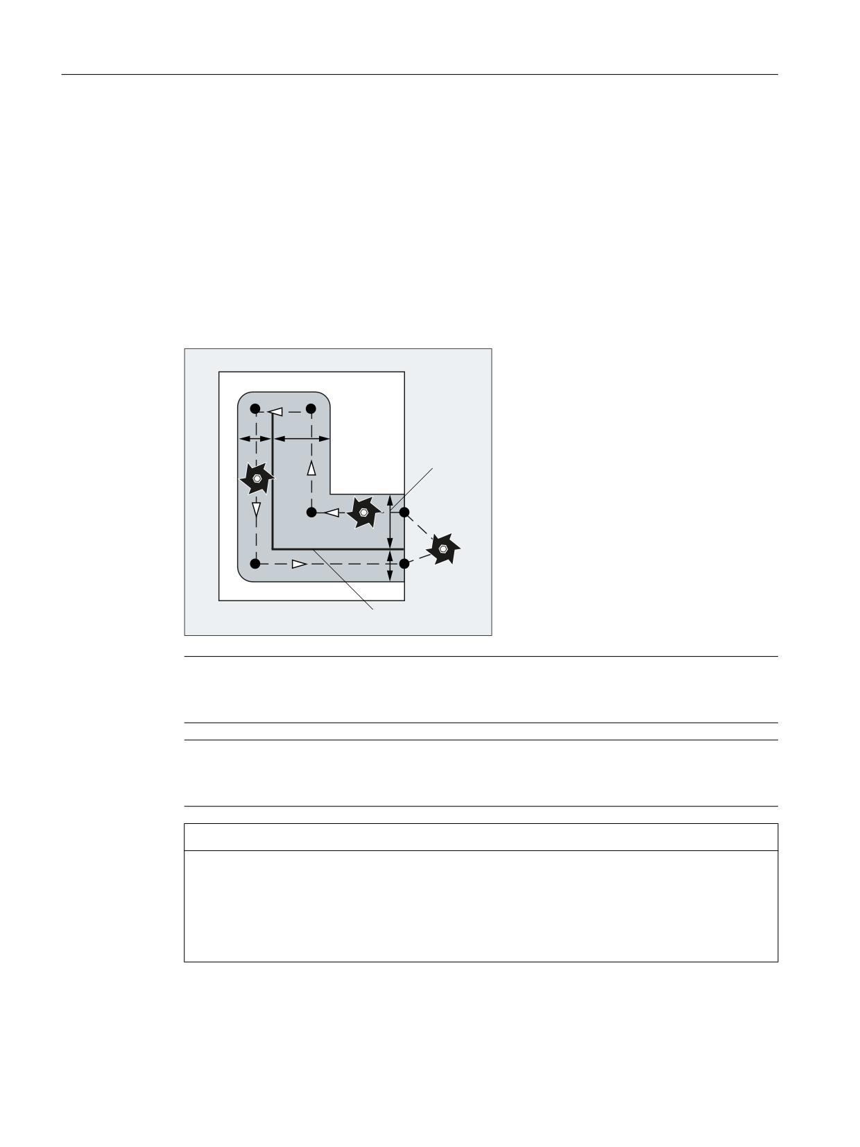
Contour offset (OFFN)
In order to mill grooves using TRACYL transformation 513, the center line of the groove and
half of the groove width via the OFFN address are programmed in the part program.
To avoid damage to the groove side, OFFN acts only when the tool radius compensation is
active.
It is possible to change OFFN within a part program. This allows the groove center line to be
offset from the center:
2))1
3URJUDPPHG SDWK
Note
OFFN should be at least as large as the tool radius to avoid damage occurring to the opposite
side of the groove wall.
Note
OFFN acts differently with TRACYL than it does without TRACYL. Since, even without
TRACYL, OFFN is included when TRC is active, OFFN should be reset to zero after TRAFOOF.
NOTICE
Effect of OFFN depends on the transformation type
For TRACYL transformation 513 (TRACYL with groove side offset), half the groove width is
programmed for OFFN.
For TRACYL transformation 512 (TRACYL with groove side offset), the value of OFFN acts
as an allowance for the TRC.
Job Planning
362
Programming Manual, 12/2018, A5E40869460B AB

Transformations
7.8 Kinematic transformation
Tool radius compensation (TRC)
For TRACYL transformation 513, the TRC is not taken into account relative to the groove side,
but to the programmed center of the groove. In order that the tool travels to the left of the
groove side, statement G42 must be programmed instead of G41 or the value of OFFN
specified with a negative sign.
Tool diameter
With TRACYL and a tool whose diameter is less than the groove width, the same groove side
geometry is not generated as with a tool whose diameter is the same as the groove width. To
improve the precision, it is recommended that the tool diameter is selected to be only slightly
less than the groove width.
Axis utilization
Note
The following axes cannot be used as a positioning axis or a reciprocating axis:
● The geometry axis in the peripheral direction of the cylinder peripheral surface (Y axis).
● The additional linear axis for groove side compensation (Z axis).
7.8.3
Activating an oblique angle transformation with programmable angle (TRAANG)
The oblique angle transformation with programmable angle is activated in the part program or
synchronized action using the TRAANG statement.
Syntax
TRAANG
TRAANG()
TRAANG(, <n>)
TRAANG(<α>)
TRAANG(<α>,<n>)
Meaning
TRAANG:
Activate TRAANG with the first TRAANG data set and last valid angle
<α>
TRAANG():
TRAANG(, <n>):
Activate TRAANG with the <n>th TRAANG data set and last valid angle
<α>
TRAANG(<α>):
Activate TRAANG with the first TRAANG data set and angle <α>
TRAANG(<α>,<n>):
Activate TRAANG with the <n>th TRAANG data set and angle <α>
<α>:
Angle of the inclined axis (optional)
Range of values:
-90° < α < + 90°
The initial state parameterized in the machine data is effective if an
angle is not specified:
MD2xxxx $MC_TRAANG_ANGLE_<n>
Job Planning
Programming Manual, 12/2018, A5E40869460B AB
363

Transformations
7.8 Kinematic transformation
<n>:
TRAANG data set number (optional)
Range of values:
1, 2
Note
Oblique angle transformation TRAANG active in the channel is deactivated using:
● Deactivate transformation: TRAFOOF
● Activation of another transformation: E.g. TRACYL, TRANSMIT, TRAORI
Example
Program code
Comment
N20 TRAANG(45)
; Activate TRAANG with the first TRAANG data set and angle 45°
7.8.4
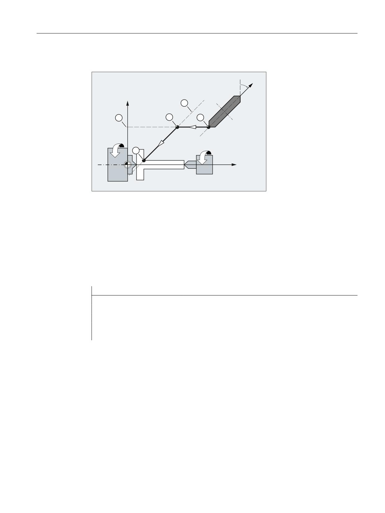
Oblique plunge-cutting on grinding machines (G5, G7)
The G commands G7 and G5 are used to simplify programming of oblique plunge-cutting on
grinding machines with "inclined axis (TRAANG)", so that when plunge cutting, only the inclined
axis is traversed.
Only the required end position of the plunge-cutting motion has to be programmed in X and
Z. For G7, starting from the actual position of the X axis, the NC calculates and approaches
the programmed end position and angle α of the inclined axis.
The starting position is calculated from the point where the two straight lines intersect:
● Straight line parallel to the Z axis, at a distance from the actual position of the X axis
● Straight line parallel to the inclined axis through the programmed end position
With the subsequent G5, the inclined axis is traversed to the programmed end position.
Syntax
G7 <Endpos_X> <Endpos_Z>
G5 <Endpos_X>
Meaning
G7:
Calculate the starting position for the oblique plunge-cutting and approach.
G5:
Traverse the inclined axis to the programmed end position
<Endpos_X>:
X axis end position
<Endpos_Z>:
End position of the Z axis
Job Planning
364
Programming Manual, 12/2018, A5E40869460B AB
Transformations
7.8 Kinematic transformation
Example
˞
80
*ULQGLQJ ZKHHO
;
1
&0
1
$60
=
=0
:RUNSLHFH
① Parallel to the Z axis, at a distance from the actual position of the X axis
② Parallel to the inclined axis through the programmed end position
③ Starting position
④ Plunge-cutting: Starting position
⑤ Plunge-cutting: End position
X
Geometry axis
Z
Geometry axis
ZM Machine axis
UM Machine axis
Program code
Comment
N... G18
; Select XZ plane.
N40 TRAANG (45.0)
; Activate TRAANG transformation, angle = 45°
N50 G7 X40 Z70 F4000
; Calculate the starting position and approach
N60 G5 X40 F100
; Traverse inclined axis to the end position.
N70 ...
Job Planning
Programming Manual, 12/2018, A5E40869460B AB
365

Transformations
7.9 Activate concatenated transformation (TRACON)
7.9
Activate concatenated transformation (TRACON)
A configured concatenated (chained) transformation is activated in the part program or
synchronized action using the TRACON statement.
Syntax
TRACON(<Trafo_No>,<Par_1>,...,<Par_n>,<Par_n+1>)
TRAFOOF
Meaning
TRACON:
Activate concatenated transformation
If another transformation was previously activated, it is implicitly dis-
abled by means of TRACON().
<Trafo_No>:
Number of the concatenated transformation:
Type:
INT
Range of val-
0 ... 2
ues:
Value:
0, 1
First/only concatenated transformation
2
Second concatenated transformation
Not
Same meaning as with 0 or 1
speci-
fied
Note:
Values not equal to 0, 1, 2 generate an error
alarm.
<Par_1>, ..., <Par_n>,
Parameters for the concatenated transformations
<Par_n+1>:
<Par_1>, ..., <Par_n>
Parameters of the first transforma-
tion in the chain
The actual number depends on
the transformation type:
● TRAORI: 2 parameters
● TRACYL: 1 to 2 parameters
<Par_n+1>
Parameters of the second transfor-
mation in the chain (TRAANG)
≙ angle of the inclined axis
If parameters are not set, the defaults or the parameters last used
take effect. Commas must be used to ensure that the specified pa-
rameters are evaluated in the sequence in which they are expected,
if default settings are to be effective for previous parameters. In
particular, a comma is required before at least one parameter, even
though it is not necessary to specify <Trafo_No> - for example TRA-
CON( , 3.7).
TRAFOOF:
Deactivate the last activated (concatenated) transformation
Job Planning
366
Programming Manual, 12/2018, A5E40869460B AB
Transformations
7.9 Activate concatenated transformation (TRACON)
Example
Program code
Comment
N230 TRACON(1,45.)
; Activate first concatenated transformation.
; The previously active transformation is automatically de-
selected.
; The angle for the inclined axis is 45°.
N330 TRACON(2,40.)
; Activate second concatenated transformation.
; The angle for the inclined axis is 40°.
N380 TRAFOOF
; Deactivate second concatenated transformation.
Job Planning
Programming Manual, 12/2018, A5E40869460B AB
367
Transformations
7.10 Cartesian PTP travel
7.10
Cartesian PTP travel
7.10.1
Activating/deactivating Cartesian PTP travel (PTP, PTPG0, PTPWOC, CP)
The Cartesian point-to-point or PTP travel is activated/deactivated in the NC program using
G group 49 commands.
The commands are modal. The default setting is travel with Cartesian path motion (CP).
Contrary to CP, for active PTP travel, only the Cartesian target point is transformed, and the
machine axes are traversed in synchronism.
In order that the Cartesian target point can be uniquely converted into machine axis values,
in addition to position and angular data, information is also necessary that identifies the axis
positions. This data is retrieved from the adjustable addresses STAT (Page 369) andTU
(Page 373).
Precondition
Transformation TRAORI, TRANSMIT, RCTRA or ROBX is active.
Syntax
PTP / PTPG0 / PTPWOC
CP
Meaning
PTP:
Activating point-to-point motion PTP
The programmed Cartesian position in G0 and G1 blocks is approached with synchro-
nous axis motion.
PTPG0:
Activating point-to-point motion PTPG0
Only in G0 blocks is the programmed Cartesian position approached with synchronous
axis motion. In G1 blocks, a switchover is made to CP path motion.
PTPWOC:
Activate point-to-point movement PTPWOC (only possible if orientation transformation
is active)
Just the same as PTP, however, without any compensatory motion, which is caused
by motion of rotary axes and orientation axes.
CP:
Deactivating point-to-point motion and activating path motion CP
Cartesian path motion is executed with CP.
Note
PTPWOC
It does not make any sense to use PTPWOC in combination with a RCTRA or ROBX
transformation!
Job Planning
368
Programming Manual, 12/2018, A5E40869460B AB
Transformations
7.10 Cartesian PTP travel
Examples
See:
● Example 1: PTP travel of a 6-axis robot with ROBX transformation (Page 376)
● Example 2: PTP travel for generic 5-axis transformation (Page 377)
● Example 3: PTPG0 and TRANSMIT (Page 377)
7.10.2
Specify the position of the joints (STAT)
Position data with Cartesian coordinates and specification of the tool orientation are not
sufficient to uniquely identify the machine position, as several joint positions are possible for
the same tool orientation. Depending on the kinematics involved, there can be as many as 8
different joint positions. These different joint positions are transformation-specific.
In an order to avoid any ambiguity, the joint positions are specified under the STAT address.
Note
The control takes into account programmed STAT values only for PTP motions. They are
ignored with CP motions because a change of position is not normally possible while traversing
with an active transformation. When traversing with active CP, the position for the target point
is taken from the starting point.
Syntax
STAT=<Value>
Meaning
STAT:
Adjustable address to specify joint positions
<Value>:
Binary or decimal value
Contains one bit for each possible position. The significance of the bits is defined by
the particular transformation.
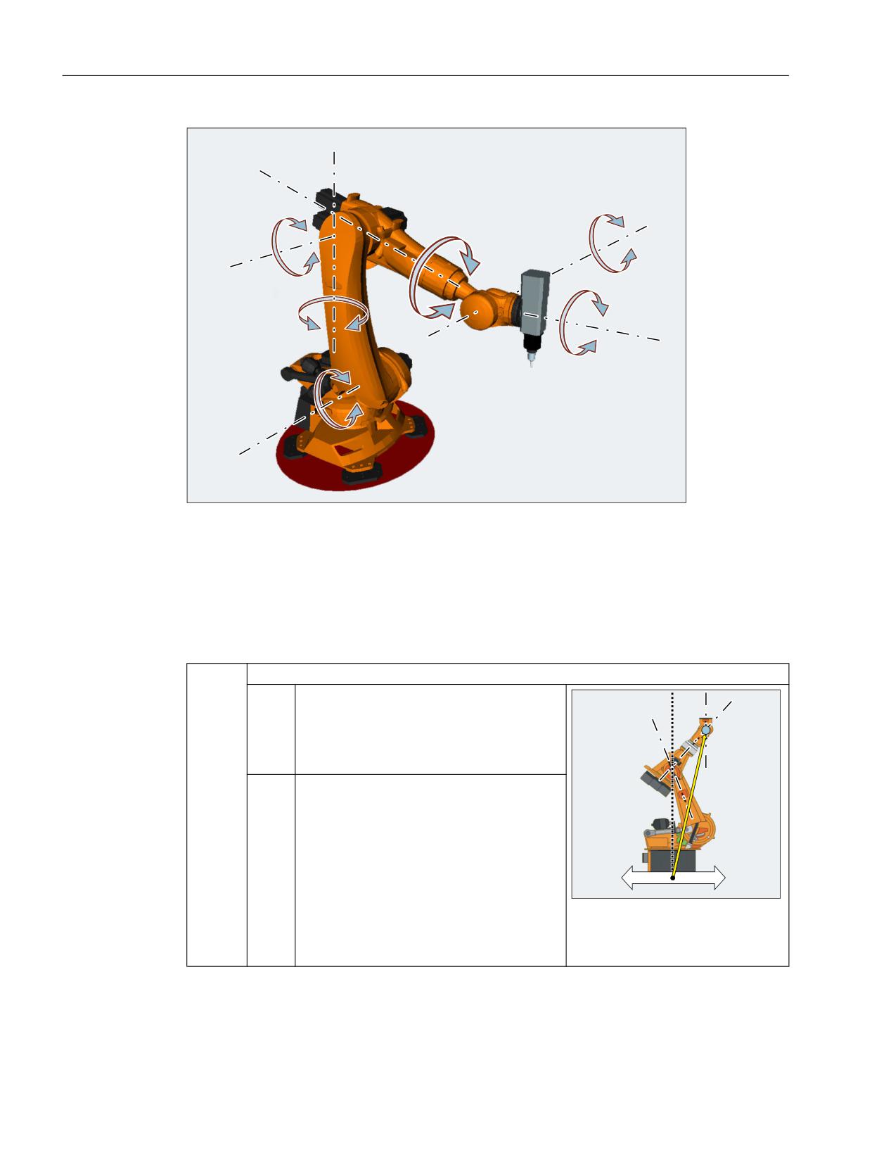
The use of STAT is to be illustrated by the example of a 6-axis articulated robot with milling
spindle. The kinematic transformation is to be realized using the ROBX robot transformation
(precondition: Compile cycle "RMCC/ROBX Transformation Extended Robotics" is loaded and
active).
Job Planning
Programming Manual, 12/2018, A5E40869460B AB
369
Transformations
7.10 Cartesian PTP travel
$
$
$
$
$
$
Axes A1, A2 and A3 are the main axes of the articulated robot. The axes A4, A5 and A6, which
are also designated as head or hand/wrist axes, are positioned in the working area with the
main axes. The additional motion options of the hand/wrist axes enable the milling spindle to
be orientated in space as required for the particular machining task. Various articulated joint
positions are possible to achieve the same tool orientation.
The articulated joint positions required for machining are selected by programming bit 0 ... 2
of the adjustable STAT address:
Bit 0
Position of the intersection points of the hand/wrist axes (A4, A5, A6)
= 0
Basic range (shoulder right)
The robot is in the basic range if the X value
of the intersection point of the hand/wrist ax-
es is positive in relation to to the A1 coordi-
nate system.
= 1
Overhead range (shoulder left)
%LW
%LW
The robot is in the overhead range if the X
value of the intersection point of the hand/
wrist axes is negative in relation to the A1
coordinate system.
;
;
$
Example: The intersection point of
the hand/wrist axes lies in the basic
range
Job Planning
370
Programming Manual, 12/2018, A5E40869460B AB
Transformations
7.10 Cartesian PTP travel
Bit 1
Position of axis 3
The angle at which the value of bit 1 changes depends on the particular robot type. The
following applies to robots whose axes 3 and 4 intersect:
= 0
A3 <0° (elbow down)
= 1
A3 ≥0° (elbow up)
Note:
For robots with an offset between axes 3 and 4, the
angle at which the value of bit 1 changes depends on
the magnitude of this offset.
Offset between A3 and A4
Bit 2
Position of axis 5
= 0
A5 ≥0° (no handflip)
= 1
A5 <0° (handflip)
Program example:
Program code
Comment
N14 T="T8MILLD20" D1
; $TC_DP3[1,1]=132.95
N16 ORIMKS
N17 G1 PTP X1665.67 Y0 Z1377.405 A=0 B=0 C=0 STAT=... F2000
; The STAT value defines
the articulated joint
positions (see below)
STAT=1 ('B001')
→ Shoulder left
→ Elbow down
→ No handflip
Job Planning
Programming Manual, 12/2018, A5E40869460B AB
371
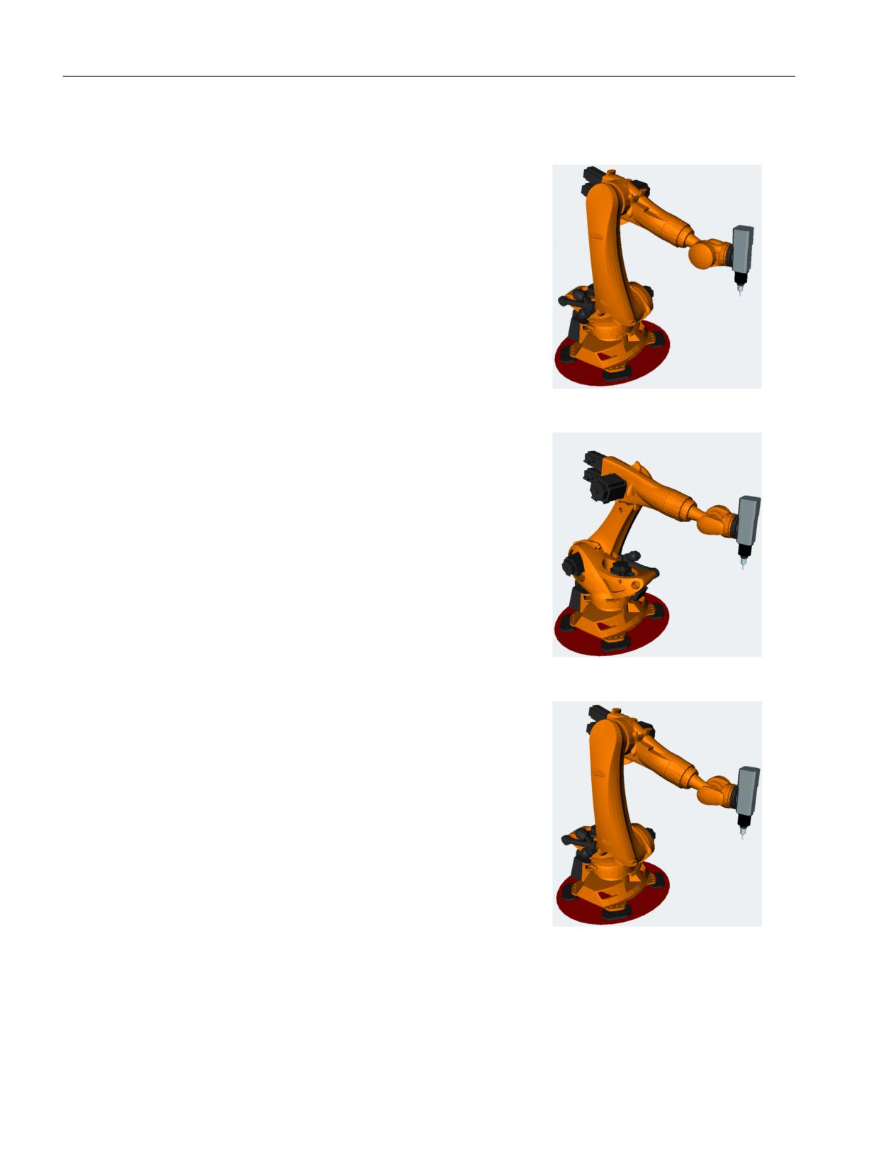
Transformations
7.10 Cartesian PTP travel
STAT=2 ('B010')
→ Shoulder right
→ Elbow up
→ No handflip
STAT=5 ('B101')
→ Shoulder left
→ Elbow down
→ Handflip
STAT=6 ('B110')
→ Shoulder right
→ Elbow up
→ Handflip
TRANSMIT
For TRANSMIT, the STAT address is used to initiate the equivocality regarding the pole.
Job Planning
372
Programming Manual, 12/2018, A5E40869460B AB

Transformations
7.10 Cartesian PTP travel
The following applies if the rotary axis must rotate through 180º or the contour for CP would
go through the pole:
Bit 0
Only relevant for $MC_TRANSMIT_POLE_SIDE_FIX_1/2 = 1 or 2:
= 0
Rotary axis traverses through +180º or rotates clockwise.
= 1
Rotary axis rotates through -180º or rotates counterclockwise.
Bit 1
Only relevant for $MC_TRANSMIT_POLE_SIDE_FIX_1/2 = 0:
= 0
The axis traverses through the pole. The rotary axis does not rotate.
= 1
The axis rotates around the pole. Bit 0 of STAT is relevant.
7.10.3
Specify the sign of the axis angle (TU)
In order that rotary axes can also approach axis angles exceeding +180° or less than -180°
without requiring a special traversing strategy (e.g. intermediate point), the sign of the axis
angle must be specified under the adjustable address TU.
Note
The control only takes into account programmed TU values for PTP motion. CP motion is
ignored.
Syntax
TU=<Value>
Meaning
TU:
Adjustable address to specify axis angle signs
<Value>:
Binary or decimal value
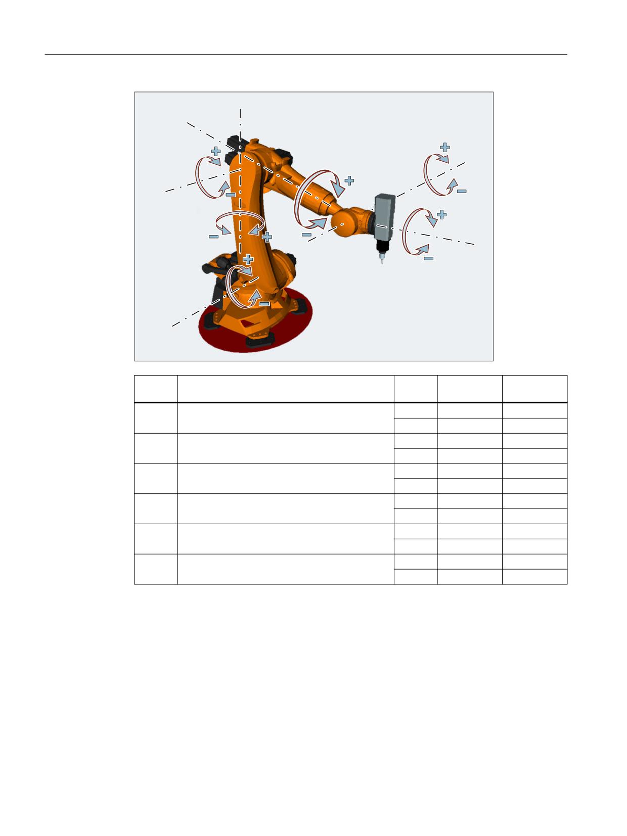
For each axis that is involved in the transformation, there is a bit that indicates the sign
of the axis angle (θ), and therefore the traversing direction.
Bit
= 0
Axis angle sign: +
Axis angular range: 0° ≤ θ < 360°
= 1
Axis angle sign: -
Axis angular range: - 360° < θ < 0°
Example: 6-axis articulated robot
Job Planning
Programming Manual, 12/2018, A5E40869460B AB
373
Transformations
7.10 Cartesian PTP travel
$
$
$
$
$
$
Bit
Meaning
Value
Axis angle
Axis angle
sign
Bit 0 1)
Sign for the axis angle of A1
= 0
+
≥ 0°
= 1
-
< 0°
Bit 1 1)
Sign for the axis angle of A2
= 0
+
≥ 0°
= 1
-
< 0°
Bit 2 1)
Sign for the axis angle of A3
= 0
+
≥ 0°
= 1
-
< 0°
Bit 3 1)
Sign for the axis angle of A4
= 0
+
≥ 0°
= 1
-
< 0°
Bit 4 1)
Sign for the axis angle of A5
= 0
+
≥ 0°
= 1
-
< 0°
Bit 5 1)
Sign for the axis angle of A6
= 0
+
≥ 0°
= 1
-
< 0°
1)
The actual TU bit numbers obtained from the channel axis numbers of the robot axes! In the example,
robot axes (A1 to A6) are the first six axes in the channel; as a consequence, TU bits 0 ... 5 are used.
For another channel axis assignment of the robot axes, the TU bit numbers of the robot axes would
correspondingly change (e.g.: robot axes are the 3rd to 8th channel axis, i.e. TU bits 2 ... 7 are used
for the robot axes).
TU=19 (corresponds to TU='B010011) would therefore signify:
Bit
Value
Axis angle
0
= 1
①
θA1 < 0°
1
= 1
①
θA2 < 0°
Job Planning
374
Programming Manual, 12/2018, A5E40869460B AB

Transformations
7.10 Cartesian PTP travel
2
= 0
①
θA3 ≥ 0°
3
= 0
①
θA4 ≥ 0°
4
= 1
①
θA5 < 0°
5
= 0
①
θA6 ≥ 0°
Note
In the case of axes with a traversing range > ±360°, the axis always moves along the shortest
path because the axis position cannot be specified uniquely by the TU information.
If no TU is programmed for a position, then depending on MD30455
$MA_MISC_FUNCTION_MASK, the shorter or longer path is traversed (see Chapter "Taking
into account the software limits for PTP travel" in the Extended Functions Function Manual).
TRANSMIT
For PTP travel with TRANSMIT active, the address of TU has no meaning!
Example
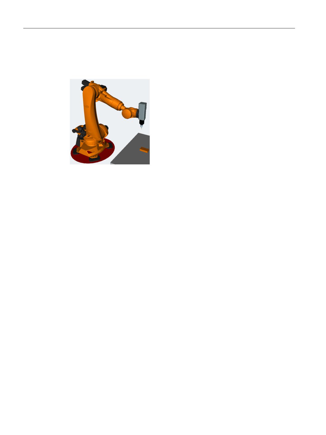
The rotary axis position shown in the following diagram can be approached in the negative or
positive direction. The angular position is programmed under address A1. The traversing
direction is only absolutely clear when TU is specified.
6WDUWLQJ SRVLWLRQ
1HJDWLYH GLUHFWLRQ
$
r 78 ELW
3RVLWLYH GLUHFWLRQ
$
r 78 ELW
7DUJHW SRVLWLRQ
Job Planning
Programming Manual, 12/2018, A5E40869460B AB
375
Transformations
7.10 Cartesian PTP travel
7.10.4
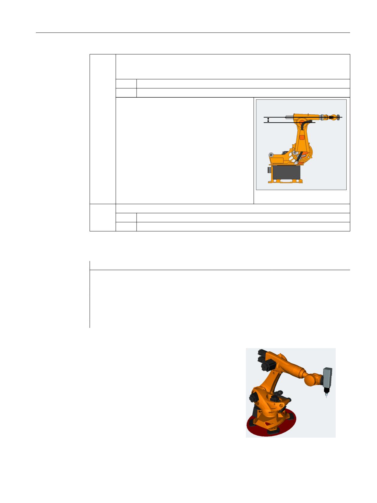
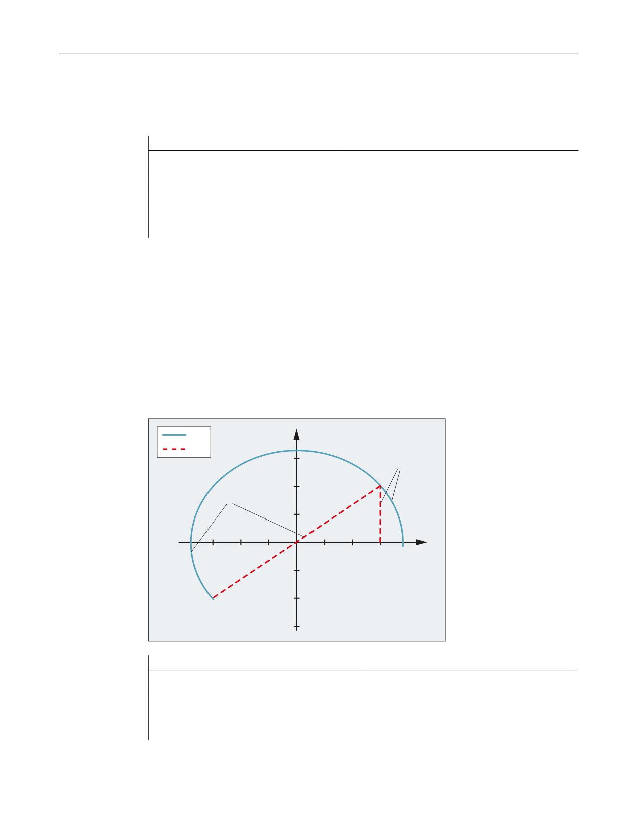
Example 1: PTP travel of a 6-axis robot with ROBX transformation
In the following application example, Cartesian PTP travel and the associated NC commands
are shown in the form of an example.
Figure 7-3
6-axis articulated robot with milling spindle
N1 G90
N2 T=“T8MILLD20“ D1 M6
N3 TRAORI
;$P_UIFR[1]=CTRANS(X,1500,Y,0,Z,400):CROT(X,0,Y,0,Z,-90)
N4 G54
N5 M3 S20000
N6 ORIWKS
N7 ORIVIRT1
N8 CYCLE832(0.01,_FINISH,1)
;HOME
N9 TRAFOOF
N10 G0 RA1=0.0000 RA2=-90.0000 RA3=90.0000 A=0.0000 B=90.0000 C=0.0000
N11 TRAORI
N12 G54
N13 G0 PTP X1369.2426 Y956.7528 Z502.5517 A=135.5761 B=-33.2223 C=161.1435
STAT='B010' TU='B001011'
N14 G0 X1355.1242 Y1014.9394 Z424.9695 A=135.8491 B=-33.1439 C=160.9941
STAT='B010' TU='B001011'
N15 G1 CP X1354.8361 Y1016.1269 Z423.3862 A=136.0635 B=-33.0819 C=160.8770
F1000
N16 G1 X1336.4283 Y1016.1269 Z426.6311 A=136.0484 B=-32.2151 C=160.9643
F2000
N17 G1 X1317.9831 Y1016.1269 Z429.6730 A=136.0175 B=-31.3394 C=161.0655
;HOME
N18 TRAFOOF
N19 G0 RA1=0.0000 RA2=-90.0000 RA3=90.0000 A=0.0000 B=90.0000 C=0.0000
N20 M30
Job Planning
376
Programming Manual, 12/2018, A5E40869460B AB
Transformations
7.10 Cartesian PTP travel
7.10.5
Example 2: PTP travel for generic 5-axis transformation
Assumption: Right-angled CA kinematics used as basis.
Program code
Comment
TRAORI
;Transformation CA kinematics ON
PTP
; Activate PTP traversal
N10 A3=0 B3=0 C3=1
; rotary axis positions C=0 A=0
N20 A3=1 B3=0 C3=1
; rotary axis positions C=90 A=45
N30 A3=1 B3=0 C3=0
; rotary axis positions C=90 A=90
N40 A3=1 B3=0 C3=1 STAT=1
; rotary axis positions C=270 A=-45
Select clear approach position of rotary axis position:
In block N40, the rotary axes - as a result of the programming of STAT=1 - travel the longer
distance from their start point (C=90, A=90) to the end point (C=270, A=-45). On the other
hand, with STAT=0, the rotary axes would travel along the shortest path to the end point (C=90,
A=45).
7.10.6
Example 3: PTPG0 and TRANSMIT
Traversing around the pole with PTPG0 and TRANSMIT
<
PTP
CP
1
* ;
<
1
;
<
;
Program code
Comment
N001 G0 X30 Z0 F10000 T1 D1 G90
;Initial setting absolute dimension
N002 SPOS=0
N003 TRANSMIT
;TRANSMIT transformation
N010 PTPG0
; for each G0 block, automatically PTP -
and then CP again.
Job Planning
Programming Manual, 12/2018, A5E40869460B AB
377
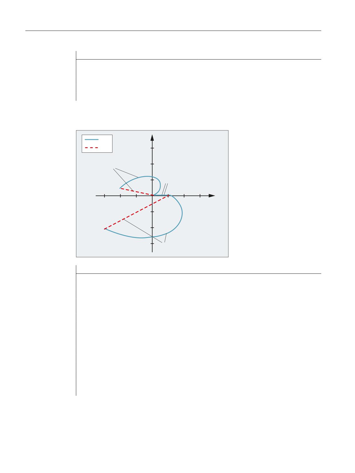
Transformations
7.10 Cartesian PTP travel
Program code
Comment
N020 G0 X30 Y20
N030 X-30 Y-20
N120 G1 X30 Y20
N110 X30 Y0
M30
Traversing from the pole with PTPG0 and TRANSMIT
<
PTP
CP
30
N070 X20 Y2
20
10
N060 X0 Y0
-30
-20
-10
10
20
30
;
-10
-20
-30
N050 X10 Y0
Programming
Comment
N001 G0 X90 Z0 F10000 T1 D1 G90
;Initial setting
N002 SPOS=0
N003 TRANSMIT
;TRANSMIT transformation
N010 PTPG0
; for each G0 block, automatically PTP -
and then CP again.
N020 G0 X90 Y60
N030 X-90 Y-60
N040 X-30 Y-20
N050 X10 Y0
N060 X0 Y0
N070 X-20 Y2
N170 G1 X0 Y0
N160 X10 Y0
N150 X-30 Y-20
M30
Job Planning
378
Programming Manual, 12/2018, A5E40869460B AB
Transformations
7.11 Constraints when selecting a transformation
7.11
Constraints when selecting a transformation
Function
Transformations can be selected via a part program or MDA. Please note:
● No intermediate movement block is inserted (chamfer/radii).
● Spline block sequences must be excluded; if not, a message is displayed.
● Fine tool compensation must be deselected (FTOCOF); if not a message is displayed.
● Tool radius compensation must be deselected (G40); if not a message is displayed.
● An activated tool length offset is included in the transformation by the control.
● The control deselects the current frame active before the transformation.
● The control deselects an active operating range limit for axes affected by the transformation
(corresponds to WALIMOF).
● Protection zone monitoring is deselected.
● Continuous path control and rounding are interrupted.
● All the axes specified in the machine data must be synchronized relative to a block.
● Axes that are exchanged are exchanged back; if not, a message is displayed.
● A message is output for dependent axes.
Tool change
Tools may only be changed when the tool radius compensation function is deselected.
A change in tool length offset and tool radius compensation selection/deselection must not be
programmed in the same block.
Frame change
All statements, which refer exclusively to the base coordinate system, are permissible
(FRAME, tool radius compensation). However, a frame change with G91 (incremental
dimension) - unlike with an inactive transformation - is not handled separately. The increment
to be traveled is evaluated in the workpiece coordinate system of the new frame - regardless
of which frame was effective in the previous block.
Exceptions
Axes affected by the transformation cannot be used
● as a preset axis (alarm),
● for approaching a checkpoint (alarm),
● for referencing (alarm).
Job Planning
Programming Manual, 12/2018, A5E40869460B AB
379
Transformations
7.12 Deselecting a transformation (TRAFOOF)
7.12
Deselecting a transformation (TRAFOOF)
The predefined TRAFOOF procedure deactivates all active transformations and frames.
Note
For deselecting the transformation, the same secondary conditions (Page 379) apply as for
selecting.
Frames required after this must be activated by renewed programming.
Syntax
TRAFOOF
Meaning
TRAFOOF:
Deactivating all active transformations/frames
Job Planning
380
Programming Manual, 12/2018, A5E40869460B AB
Kinematic chains
8
8.1
Deletion of components (DELOBJ)
The DELOBJ() function "deletes" components by resetting the assigned system variables to
their default values:
● Elements from kinematic chains
● Protection areas, protection area elements and collision pairs
● Transformation data
Syntax
[<RetVal>=] DELOBJ(<CompType>[,,,<NoAlarm>)])
[<RetVal>=] DELOBJ(<CompType>,<Index1>[,,<NoAlarm>])
[<RetVal>=] DELOBJ(<CompType>[,<Index1>][,<Index2>][,<NoAlarm>])
Job Planning
Programming Manual, 12/2018, A5E40869460B AB
381

Kinematic chains
8.1 Deletion of components (DELOBJ)
Meaning
DELOBJ:
Deletion of elements from kinematic chains, protection areas, protection area ele-
ments, collision pairs and transformation data
<CompType>:
Component type to be deleted
Data type:
STRING
Value: "KIN_CHAIN_ELEM"
Meaning: System variables of all kinematic elements: $NK_...
Value: "KIN_CHAIN_SWITCH"
Meaning: System variable $NK_SWITCH[<i>]
Value: "KIN_CHAIN_ALL"
Meaning: All kinematic elements and switches.
Is the same as the successive call of DELOBJ with "KIN_CHAIN_ELEM" and
"KIN_CHAIN_SWITCH"
Value: "PROT_AREA"
Meaning: System variables of the protection areas:
● $NP_PROT_NAME
● $NP_CHAIN_NAME
● $NP_CHAIN_ELEM
● $NP_1ST_PROT
Value: "PROT_AREA_ELEM"
Meaning: System variables of the protection area elements of machine protection
areas and/or automatic tool protection areas:
● $NP_NAME
● $NP_NEXT
● $NP_NEXTP
● $NP_COLOR
● $NP_D_LEVEL
● $NP_USAGE
● $NP_TYPE
● $NP_FILENAME
● $NP_PARA
● $NP_OFF
● $NP_DIR
● $NP_ANG
Value: "PROT_AREA_COLL_PAIRS"
Meaning: System variables of the collision pairs:
● $NP_COLL_PAIR
● $NP_SAFETY_DIST
Value: "PROT_AREA_ALL"
Meaning: All protection areas, protection area elements and collision pairs (system
variable $NP_... )
Is the same as the successive call of DELOBJ with "PROT_AREA,"
"PROT_AREA_ELEM," and "PROT_AREA_COLL_PAIRS"
Value: "TRAFO_DATA"
Meaning: System variables of all transformations $NT_...
Job Planning
382
Programming Manual, 12/2018, A5E40869460B AB

Kinematic chains
8.1 Deletion of components (DELOBJ)
<Index1>:
Index of the first component to be deleted (optional)
Data type:
INT
Default value:
-1
Range of val-
-1 ≤ x ≤ (maximum number of configured components -1)
ues:
Value
Meaning
0, 1, 2,
Index of the component to be deleted.
-1
All components of the specified type are deleted. <Index2> is not
evaluated.
<Index2>:
Index of the last components to be deleted (optional)
If <Index2> is not programmed, only the system variables of the component refer-
enced in <Index1> are deleted.
Data type:
INT
Default value:
Only the system variables of the component referenced in <In-
dex1> are deleted.
Range of val-
<Index1> < x ≤ (max. number of configured components -1)
ues:
<NoAlarm>:
Alarm suppression (optional)
Data type:
BOOL
Default value:
FALSE
Value
Meaning
FALSE
In the event of an error (<RetVal> < 0), program processing is
stopped and an alarm displayed.
TRUE
In the event of an error, the program processing is not stopped
and no alarm displayed.
Application: User-specific reaction corresponding to the return
value
<RetVal>:
Function return value
Data type:
INT
Range of val-
0, -1, -2, ... -7
ues:
Value
Meaning
0
No error occurred.
-1
Call of the function without parameters. At least parameter
<CompType> must be specified.
-2
<CompType> identifies an unknown component
-3
<Index1> is less than -1
-4
<Index1> is greater than the configured number of components
-5
<Index1> has a value not equal to -1 when deleting a component
group
-6
<Index2> is less than <Index1>
-7
<Index2> is greater than the configured number of components
Job Planning
Programming Manual, 12/2018, A5E40869460B AB
383

Kinematic chains
8.2 Index determination by means of names (NAMETOINT)
8.2
Index determination by means of names (NAMETOINT)
User-specific names are entered in the system variable arrays of type STRING. Based on the
identifier of the system variables and the name, the NAMETOINT() function determines the
index value belonging to the name under which it is stored in the system variable array.
Syntax
<RetVal> = NAMETOINT(<SysVar>,<Name>[,<NoAlarm>])
Meaning
NAMETOINT:
Determining the system variable index
<SysVar>:
Name of the system variable array of typeSTRING
Data type:
STRING
Range of val-
Name of all NC system variable arrays of type STRING
ues:
<Name>:
Character string or name for which the system variable index is to be determined.
Data type:
STRING
<NoAlarm>:
Alarm suppression (optional)
Data type:
BOOL
Default value:
FALSE
Value
Meaning
TRUE
In the event of an error, the program processing is not stopped
and no alarm displayed.
Application: User-specific reaction corresponding to the return
value
FALSE
In the event of an error (<RetVal> < 0), program processing is
stopped and an alarm displayed.
<RetVal>:
System variable index or error message
Data type:
INT
Range of val-
-1 ≤ x ≤ (max. number of configured components -1)
ues:
Value
Meaning
≥ 0
The sought name has been found under the specified system
variable index.
-1
The sought name has not been found or an error has occurred.
Example
Program code
Comment
DEF INT INDEX
$NP_PROT_NAME[27]="Cover"
INDEX = NAMETOINT("$NP_PROT_NAME","Cover")
; INDEX == 27
Job Planning
384
Programming Manual, 12/2018, A5E40869460B AB
Collision avoidance with kinematic chains
9
Note
Protection areas
The protection areas specified in the following chapters refer to the "Geometric machine
modeling" function
References:
Function Manual, Special Functions, Chapter "Geometric machine modeling"
Job Planning
Programming Manual, 12/2018, A5E40869460B AB
385

Collision avoidance with kinematic chains
9.1 Check for collision pair (COLLPAIR)
9.1
Check for collision pair (COLLPAIR)
The COLLPAIR() function determines whether two protection areas form a collision pair.
Syntax
[<RetVal> =] COLLPAIR(<Name_1>,<Name_2>[,<NoAlarm>)])
Meaning
COLLPAIR:
Check whether part of a collision pair
<RetVal>:
Function return value
Data type:
INT
Value:
≥ 0
The two protection zones form a collision pair.
Return value == collision pair index m (see
$NP_COLL_PAIR)
-1
Either two strings have not been specified or at least
one of the two is the zero string.
-2
The protection zone specified in the first parameter has
not been found.
-3
The protection zone specified in the second parameter
has not been found.
-4
Neither of the two specified protection zones has been
found.
-5
Both specified protection zones have been found, but
not together in a collision pair.
<Name_1>:
Name of the first protection zone
Data type:
STRING
Range of val-
Parameterized protection zone names
ues:
<Name_2>:
Name of the second protection area
Data type:
STRING
Range of val-
Parameterized protection zone names
ues:
<NoAlarm>:
Alarm suppression (optional)
Data type:
BOOL
Value:
FALSE (Default)
In the event of an error (<RetVal> < 0), the
program processing is stopped and an alarm
displayed.
TRUE
In the event of an error, the program process-
ing is not stopped and no alarm displayed.
Application: User-specific reaction corre-
sponding to the return value
Job Planning
386
Programming Manual, 12/2018, A5E40869460B AB

Collision avoidance with kinematic chains
9.2 Request recalculation of the machine model of the collision avoidance (PROTA)
9.2
Request recalculation of the machine model of the collision avoidance
(PROTA)
If system variables of the kinematic chain $NK_..., the geometric machine modeling or the
collision avoidance $NP_... are written in the part program, the PROTA procedure must
subsequently be called so that the change becomes effective in the NC-internal machine model
of the collision avoidance.
Syntax
PROTA[(<Par>)]
Meaning
PROTA:
Request recalculation of the machine model of the collision avoidance
● Triggers a preprocessing stop.
● Must be alone in the block.
<Par>:
Parameter (optional)
Data type:
STRING
Value:
---
No parameters.
The machine model is recalculated. The states of the pro-
tection areas are retained.
"R"
The machine model is recalculated. The protection areas
are set to their initialization status corresponding to
$NP_INIT_STAT.
Supplementary conditions
Simulation
The PROTA procedure must not be used in part programs in conjunction with the simulation
(simNC).
Example: Avoiding the PROTA call while the simulation is active.
Program code
Comment
IF $P_SIM == FALSE
; IF simulation not active
PROTA
THEN recalculate collision model
ENDIF
; ENDIF
See also
Setting the protection zone status (PROTS) (Page 388)
Job Planning
Programming Manual, 12/2018, A5E40869460B AB
387

Collision avoidance with kinematic chains
9.3 Setting the protection zone status (PROTS)
9.3
Setting the protection zone status (PROTS)
The PROTS() procedure sets the state of protection areas to the specified value.
Syntax
PROTS(<State>[,<Name_1>,...,<Name_n>])
Meaning
PROTS:
Sets the state of protection areas
● Must be alone in the block.
<State>:
Status to which the specified protection zones are to be set
Data type:
CHAR
Value:
"A"or "a"
Status: Active
"I"or "i"
Status: Inactive
"P"or "p"
Status: Preactivated or PLC-controlled 1)
"R"or "r"
Status: NC-internal value of the initialization
status 2)
<Name_1> ...
Name of one or more protection areas that are to be set to the specified status
<Name_n>:
(optional)
If no name is specified, the specified status is set for all defined protection zones.
Data type:
STRING
Range of values:
Parameterized protection zone names
Note
The maximum number of protection areas that can be specified as parameters
depends only on the maximum possible number of characters per program line.
1) The activation/deactivation is performed via: DB10.DBX234.0 - DBX241.7
2) The status is set to the NC-internal value of the initialization status, i.e. to the value that the system
variable $NP_INIT_STAT had at the time of the last PROTA( ) (Page 387) call.
Job Planning
388
Programming Manual, 12/2018, A5E40869460B AB

Collision avoidance with kinematic chains
9.4 Determining the clearance of two protection zones (PROTD)
9.4
Determining the clearance of two protection zones (PROTD)
The PROTD() function calculates the clearance of two protection areas.
Function properties:
● The clearance calculation is performed independent of the protection area status (activated,
deactivated, preactivated).
● To calculate the clearance of two protection areas, only protection area elements are used,
which are marked with $NP_USAGE = "C" or "A". Protection area elements of the protection
area, which are marked with $NP_USAGE = "V", are not taken into consideration.
● Protection areas, where all protection area elements of the protection area are marked with
$NP_USAGE = "V", cannot be used for the clearance calculation.
● The clearance calculation is performed with the positions valid at the end of the previous
block.
● Overlays that are included in the main run calculation (e.g. DRF offset or external zero
offset) are included in the clearance calculation with the values valid at the function
interpretation time.
Note
Synchronization
When using the PROTD() function, it is the sole responsibility of the user to synchronize
the main run and preprocessing, if required, with the STOPRE preprocessing stop.
Collision
If there is a collision between the specified protection areas, the function returns a clearance
of 0.0. There is a collision if both the protection areas touch or intersect each other.
The safety clearance for the collision check (MD10622 $MN_COLLISION_SAFETY_DIST) is
not taken into account in the clearance calculation.
Syntax
[<RetVal> =] PROTD([<Name_1>],[<Name_2>],VAR <Vector>[,<System>])
Meaning
PROTD:
Calculates the clearance of the two specified protection areas.
● Must be alone in the block.
<RetVal>:
Function return value: Absolute clearance value of the two protection areas or 0.0
with collision (see above: Collision paragraph)
Data type:
REAL
Range of values:
0.0 ≤ x ≤ +max. REAL value
Job Planning
Programming Manual, 12/2018, A5E40869460B AB
389

Collision avoidance with kinematic chains
9.4 Determining the clearance of two protection zones (PROTD)
<Name_1>,
Names of the two protection areas whose clearance is to be calculated (optional)
<Name_2>:
Data type:
STRING
Range of values:
Parameterized protection area names
Default value:
"" (empty string)
If no protection areas have been specified, the function calcu-
lates the current smallest clearance from all the activated and
preactivated protection areas in the collision model.
<Vector>:
Return value: 3-dimensional clearance vector from protection area <Name_2> to
protection area <Name_1> with:
● <Vector>[0]: X coordinate in the world coordinate system
● <Vector>[1]: Y coordinate in the world coordinate system
● <Vector>[2]: Z coordinate in the world coordinate system
For collision: <Vector> == zero vector
Data type:
VAR REAL [3]
Range of values:
<Vector> [n]: 0.0 ≤ x ≤ ±max. REAL value
<System>:
Measuring system (inch/metric) for clearance and clearance vector (optional)
Data type:
BOOL
Value:
FALSE (Default)
Measuring system corresponding to the cur-
rently active G command from G group 13
(G70, G71, G700, G710).
TRUE
Measuring system corresponding to the set
basic system:
MD52806 $MN_ISO_SCALING_SYSTEM
Job Planning
390
Programming Manual, 12/2018, A5E40869460B AB

Transformation with kinematic chains
10
10.1
Activating a transformation (TRAFOON)
A transformation defined with kinematic chains is activated with the predefined TRAFOON
procedure. The call must be alone in a block.
Note
Alternatively, a transformation defined with kinematic chains can also be activated via
conventional NC commands, such as TRAORI or TRANSMIT. For this purpose, an appropriate
value, not equal to zero, must be entered in the $NT_TRAFO_INDEX system variable.
For further information on $NT_TRAFO_INDEX see "System Variables List Manual".
Syntax
TRAFOON(<Trafoname>,<Diameter>,<k>)
Meaning
TRAFOON:
Procedure for activating a transformation defined with kinematic chains
<Trafoname>:
Name of the transformation data set
Data type:
STRING
Range of val-
All names of transformation data sets defined via $NK_NAME
ues:
Note:
The name of the transformation data set must be unique. It must only occur once
in $NT_NAME.
<Diameter>:
Reference or working diameter (TRACYL only)
Data type:
REAL
The value must be > 1.
<k>:
Defines the use of the groove side offset (TRACYL only).
Data type:
BOOL
Value:
FALSE
Without groove side offset
TRUE
With groove side offset
Corresponds to the TRACYL transformation type 514 (groove side offset can be
programmed). If <k> is not specified, the parameterized setting of bit 10 in
$NT_CNTRL[<n>] applies.
Example
Program code
Comment
TRAFOON["Trans_1"]
Activates the transformation with the name Trans_1.
Job Planning
Programming Manual, 12/2018, A5E40869460B AB
391

Transformation with kinematic chains
10.2 Modifying the orientation transformation after the machine measurement (CORRTRAFO)
10.2
Modifying the orientation transformation after the machine
measurement (CORRTRAFO)
For machines with orientation transformations that were defined by means of kinematic chains,
the user can use the predefined CORRTRAFO function in order to modify the offset vectors
or the direction vectors of the orientation axes in the kinematic model of the machine after a
machine measurement.
Syntax
<Corr_Status> = CORRTRAFO(<Corr_Vect>, <Corr_Index>, <Corr_Mode>,
[ <No_Alarm>])
Meaning
CORRTRAFO:
Function call
<Corr_Status>:
Function return value
Data type:
INT
Values:
0
The function was executed without an error.
1
No transformation is active.
2
The currently active transformation is not an orientation trans-
formation.
3
The active orientation transformation was not defined with kin-
ematic chains.
10
The <Corr_Index> call parameter is negative.
11
The <Corr_Mode> call parameter is negative.
12
Invalid reference to a section of a subchain (unit position of
<Corr_Index>). The value must not be greater than the num-
ber of orientation axes in the subchain.
13
Invalid reference to the orientation axis of a subchain (unit po-
sition of <Corr_Index>). The value must be less than the
number of orientation axes in the subchain.
14
Invalid reference to a subchain (tens position of
<Corr_Index>). Only the values 0 and 1 are permissible (ref-
erence to part or tool chain). This error number occurs if the
subchain to which <Corr_Index> refers does not exist.
Job Planning
392
Programming Manual, 12/2018, A5E40869460B AB
Transformation with kinematic chains
10.2 Modifying the orientation transformation after the machine measurement (CORRTRAFO)
15
There is no correction element in the section referred to with
the <Corr_Index> parameter ($NT_CORR_ELEM_P or
$NT_CORR_ELEM_T).
20
Invalid correction mode (unit position of <Corr_Mode>). Only
the values 0 and 1 are permissible.
21
Invalid correction mode (tens and/or hundreds position of
<Corr_Mode>). Only the unit position can be not equal to zero
when writing an axis direction.
30
The hundreds position of <Corr_Mode> is invalid. Only the
values 0 and 1 are permissible.
31
The thousands position of <Corr_Mode> is invalid. Only the
values 0 and 1 are permissible.
40
The direction vector that is to be taken as axis direction is the
zero vector. This error can only happen if the thousands posi-
tion of <Corr_Mode> is equal to 0. If the thousands position
of this parameter is equal to 1 (monitoring of the maximum
correction deactivated), the zero vector can also be written.
41
For the correction of an offset vector, the difference to the cur-
rent value in at least one coordinate is greater than the maxi-
mum value specified by the setting data SD41610
$SN_CORR_TRAFO_LIN_MAX. The <Corr_Vect> parame-
ter will be overwritten by an error vector. This also applies when
the processing is aborted with alarm (see <No_Alarm> pa-
rameter).
In the components whose correction value has exceeded the
permissible limit, the error vector has the difference, with the
correct sign, between the determined correction value and the
limit.
The content of the components that have not exceeded their
limit is zero.
42
For the correction of a direction vector, the angular displace-
ment compared to the current direction is greater than the
maximum value specified by the setting data SD41611
$SN_CORR_TRAFO_DIR_MAX.
43
The attempt to write a system variable was rejected because
of missing write rights.
<Corr_Vect>:
Correction vector
The content of the correction vector is defined by the following parameters
<Corr_Index> and <Corr_Mode>.
If <Corr_Status> = 41, the content of the vector is overwritten (see above).
Data type:
REAL
<Corr_Index>:
Section whose correction element is to be modified /
index of the orientation axis whose direction vector is to be modified
Data type:
INT
The <Corr_Index> parameter is decimal coded (unit to tens position):
Unit
Contains the index of the section or the orientation axis in the sub-
position:
chain.
Tens
Refers to the subchain.
position:
0x
Workpiece chain
1x
Tool chain
Job Planning
Programming Manual, 12/2018, A5E40869460B AB
393

Transformation with kinematic chains
10.2 Modifying the orientation transformation after the machine measurement (CORRTRAFO)
<Corr_Mode>:
Correction mode
Data type:
INT
The <Corr_Index> parameter is decimal coded (unit to thousands position):
Unit
Specifies which element is to be corrected.
position:
xxx0
Correction of a linear offset vector
xxx1
Correction of the direction vector of an orientation axis
Tens
Specifies how the correction element to which the content of
position:
<Corr_Index> refers, is to be modified.
xx0x
The correction vector is written immediately to the correc-
tion element.
This variant can be used to immediately write the correction
element without the index <n> of the relevant system data
($NK_OFF_DIR[<n>, ...]) having to be known.
xx1x
As 0, but with the difference that the transferred correction
value is interpreted in world coordinates.
A difference between variants 0 and 1 can always occur
when the kinematic chain in the initial state (positions of all
orientation axes equal to 0) contains other rotations.
xx2x
As 1, but with the difference that the correction value refers
to the entire section, i.e. a value is entered in the correction
element so that the entire section reaches the length de-
fined by the correction value.
Note:
The values 1 and 2 are not permissible when writing the direction
vector of an orientation axis.
Hundreds
Specifies how the content of the <Corr_Vect> parameter is to be
position:
interpreted.
x0xx
The transferred correction vector <Corr_Vect> contains
the entire new length of the correction element or the sec-
tion to which the <Corr_Index> in conjunction with the
tens position of <Corr_Mode> refers (absolute correction).
x1xx
The transferred correction vector <Corr_Vect> only con-
tains the difference compared to the current length of the
correction element or the section to which the
<Corr_Index> in conjunction with the tens position of
<Corr_Mode> refers (incremental correction).
Note:
For the correction of the direction vector of an orientation axis, the
content of the hundreds position must be 0.
Thou-
Specifies whether the correction is to be limited by the following
sands
maximum value:
position:
● SD41610 $SN_CORR_TRAFO_LIN_MAX
or
● SD41611 $SN_CORR_TRAFO_DIR_MAX
0xxx
Monitoring of the maximum correction is active.
1xxx
Monitoring of the maximum correction is not active.
Job Planning
394
Programming Manual, 12/2018, A5E40869460B AB

Transformation with kinematic chains
10.2 Modifying the orientation transformation after the machine measurement (CORRTRAFO)
<No_Alarm>:
Behavior in the event of an error (return value > 0) (optional)
Data type:
BOOL
Value:
FALSE
In the event of an error, the program processing is stop-
(default)
ped and alarm 14103 is displayed.
TRUE
In the event of an error, the program processing is not
stopped and no alarm is displayed.
Application: User-specific reaction corresponding to the
return value
Note
In the event of an error when the function is called, either an alarm is output or an error number
returned (see <No_Alarm> parameter), so that the user can respond in a suitable way to the
error state. The cause of the error is described in more detail through an alarm parameter. An
error number returned instead of an alarm is identical to the alarm parameter.
Further information on CORRTRAFO
The kinematic structure of a machine with orientation transformation is described by one or
two kinematic chains (subchains), starting from the zero point of the world coordinate system.
One of the two chains, the tool chain, ends at the reference point of the tool, the other chain,
the workpiece chain ends in the zero point of the basic coordinate system.
The CORRTRAFO function writes lever arm lengths and axis directions on machines with an
orientation transformation in special correction elements. A kinematic chain is described, for
example, with elements of the type OFFSET, which are defined via $ NK_TYPE.
CORRTRAFO works with sections
The two subchains can each be divided into a maximum of four sections:
● Section 1 begins at the starting point of the chain and ends at the first orientation axis.
● Section 2 is the section between orientation axis 1 and orientation axis 2.
● Section 3 is the section between orientation axis 2 and orientation axis 3.
● Section 4 is the section between orientation axis 3 and the end of the tool or workpiece
chain.
Each section may contain constant chain elements of the type OFFSET or ROT_CONST.
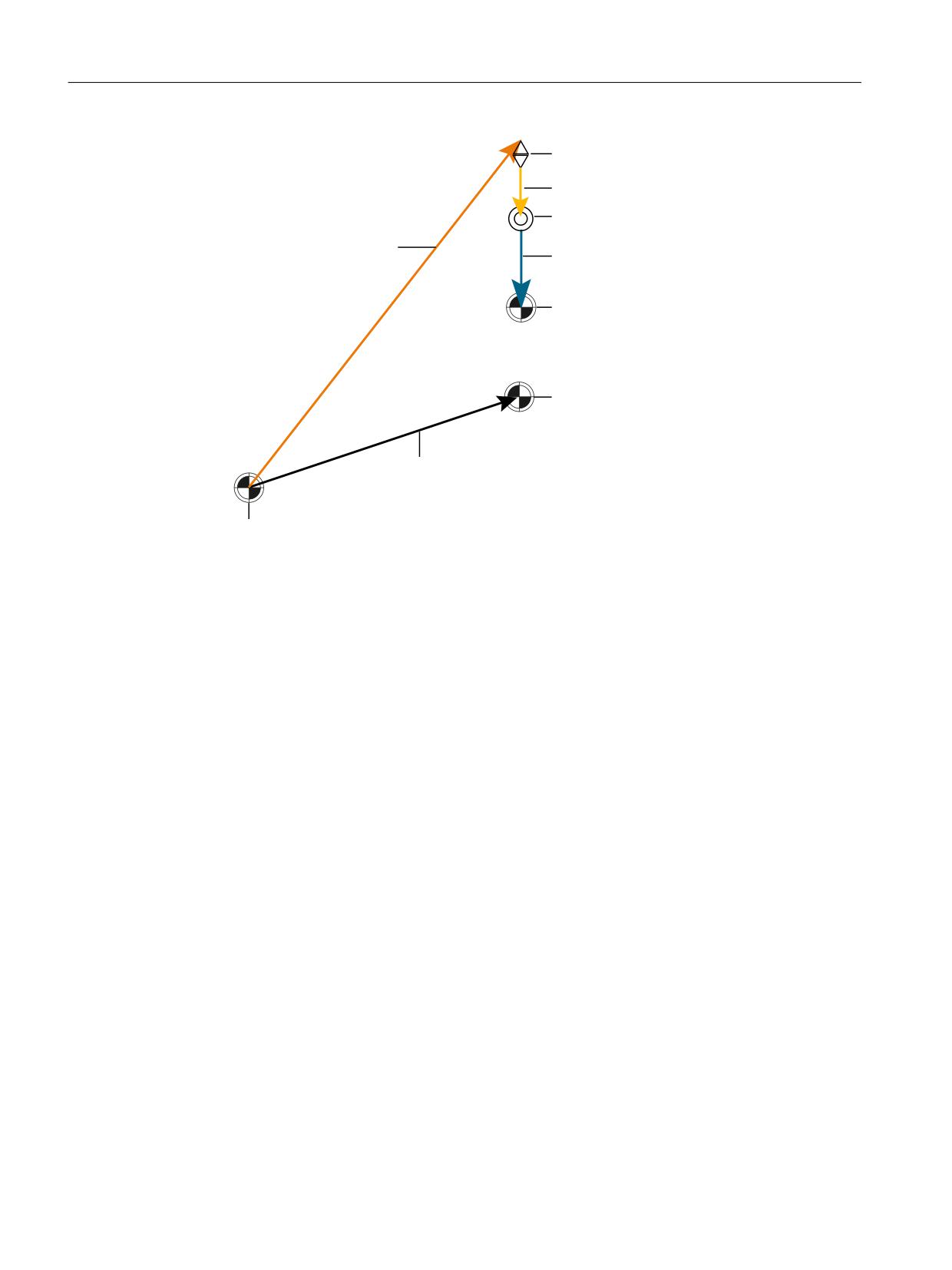
The following figure shows an orientation transformation with 2 orientation axes.
Job Planning
Programming Manual, 12/2018, A5E40869460B AB
395
Transformation with kinematic chains
10.2 Modifying the orientation transformation after the machine measurement (CORRTRAFO)
2ULHQWDWLRQ D[LV
6HFWLRQ
,QGH[
2ULHQWDWLRQ D[LV
6HFWLRQ
,QGH[
6HFWLRQ
,QGH[
7RRO UHIHUHQFH SRLQW HQG
SRLQW RI WKH WRRO FKDLQ
:RUNSLHFH UHIHUHQFH
SRLQW
7DEOH RIIVHW
=HUR SRLQW RI WKH ZRUOG
FRRUGLQDWH V\VWHP
Figure 10-1
CORRTRAFO example
The sections are clearly defined: If you run through the kinematic subchain from the starting
point to the end point, the first section has the index 0, the next the index 1, and so on. The
index of the last section is then always equal to the number of orientation axes.
Correction elements
A reference can be made to a constant kinematic chain element (chain element of the type
$NK_TYPE[<n>] = "OFFSET") in each section with the $NT_CORR_ELEM_T[<n>, 0 ... 3] or
$NT_CORR_ELEM_P[<n>, 0 ... 3] system variables. The correction values that were
determined during the machine measurement are written to these elements with the
CORRTRAFO function.
Example with transformation index = 1:
● $NT_CORR_ELEM_T[1,0] = "C_AXIS_OFFSET"; Offset of the C axis (orientation axis 1)
in section 1 is defined as correction element.
● $NT_CORR_ELEM_T[1,1] = "B_AXIS_OFFSET"; Offset of the B axis (orientation axis 2) in
section 2 is defined as correction element.
● $NT_CORR_ELEM_T[1,2] = "BASE_TOOL_OFFSET"; Offset of the B axis from the tool
reference point in section 3 is defined as correction element.
The sequence of the references in $NT_CORR_ELEM_T/P[<n>, 0 ... 3] must correspond to
the sections described above, i.e. only one chain element can be in $NT_CORR_ELEM_T/P
[<n>, 0] which is before the first orientation axis, etc.
The CORRTRAFO function writes the values determined by measuring the machine into the
correction elements defined in this way. The modification of the correction values is defined
in CORRTRAFO via the <Corr_Mode> parameter.
Job Planning
396
Programming Manual, 12/2018, A5E40869460B AB
Transformation with kinematic chains
10.2 Modifying the orientation transformation after the machine measurement (CORRTRAFO)
Closing a chain
If bit 7 or bit 8 are set in the $NT_CNTRL[<n>] system variable, additional constant chain
elements that establish a connection from the end point of the chain to the machine zero point
are automatically inserted internally at the end of the workpiece chain (bit 7) or before the
starting point of the tool chain (bit 8) ("close chain").
These automatically inserted elements cannot be written externally, only read (see the
$AC_TRAFO_CORR_ELEM_P/T system variables).
Point to close the tool chain
If the $NT_CLOSE_CHAIN_T system variable is not empty, the tool chain is not closed at the
end point of the chain, but rather at the end point of the designated chain element. Other chain
elements that are behind this point result in a corresponding work offset when the
transformation is activated.
Index of an orientation axis
In addition to the constants offsets between the orientation axes, the direction vectors of the
orientation axes can also be written with the CORRTRAFO function. The index of an orientation
axis is the index that results when the kinematic subchain is run through from the origin to the
end, where the count starts at zero. The index of an orientation axis is therefore always the
same as the index of the preceding section.
The index of an orientation axis can also be determined with the $AC_TRAFO_ORIAX_LOC
system variable.
Maximum permissible change of a chain element
The maximum permissible change of a chain element can be limited by the two setting data
SD41610 $SN_CORR_TRAFO_LIN_MAX for offset vectors and SD41611
$SN_CORR_TRAFO_DIR_MAX for direction vectors of the orientation axes. SD41610
$SN_CORR_TRAFO_LIN_MAX specifies the maximum amount by which each individual
vector component can be changed with regard to its reference value. SD41611
$SN_CORR_TRAFO_DIR_MAX specifies the maximum angle by which the direction of the
axis vector can be changed with regard to its reference value. The reference value is always
the corresponding value that is active in the transformation that is active when CORRTRAFO
is called. This means that the changed content of the kinematic data may have no effect on
the method of operation of the CORRTRAFO function after the activation of the transformation.
Job Planning
Programming Manual, 12/2018, A5E40869460B AB
397
Transformation with kinematic chains
10.2 Modifying the orientation transformation after the machine measurement (CORRTRAFO)
Job Planning
398
Programming Manual, 12/2018, A5E40869460B AB

Tool offsets
11
11.1
Offset memory
Structure of the offset memory
Every data field can be called with a T and D number, and contains not only the geometric
specifications for the tool but also further entries, such as the tool type.
User cutting edge data
User cutting edge data can be configured via machine data. Please refer to the machine
manufacturer's instructions.
Tool parameters
Note
Individual values in the offset memory
The individual values of the offset memory P1 to P25 can be read and written by the program
via system variables. All other parameters are reserved.
The tool parameters $TC_DP6 to $TC_DP8, $TC_DP10 and $TC_DP11 as well as $TC_DP15
to $TC_DP17, $TC_DP19 and $TC_DP20 have another meaning depending on tool type.
Tool parameter number (DP) Meaning of system variables
Remark
$TC_DP1
Tool type
For overview see list
$TC_DP2
Cutting edge position
Only for turning tools
Geometry
Length compensation
$TC_DP3
Length 1
Allocation to
$TC_DP4
Length 2
Type and level
$TC_DP5
Length 3
Geometry
Radius
$TC_DP6 1)
Radius 1 / length 1
Milling/turning/grinding tool
$TC_DP6 2)
diameter d
Slotting saw
$TC_DP7 1)
Length 2 / corner radius, tapered milling tool
Milling tools
$TC_DP7 2)
Slot width b corner radius
Slotting saw
$TC_DP8 1)
Rounding radius 1 for milling tools
Milling tools
$TC_DP8 2)
projecting length k
Slotting saw
$TC_DP9 1) 3)
Rounding radius 2
Reserved
$TC_DP10 1)
Angle 1 face end of tool
Tapered milling tools
$TC_DP11 1)
Angle 2 tool longitudinal axis
Tapered milling tools
Wear
Length and radius compensation
$TC_DP12
Length 1
Job Planning
Programming Manual, 12/2018, A5E40869460B AB
399
Tool offsets
11.1 Offset memory
Tool parameter number (DP) Meaning of system variables
Remark
$TC_DP13
Length 2
$TC_DP14
Length 3
$TC_DP15 1)
Radius 1 / length 1
Milling/turning/grinding tool
$TC_DP15 2)
diameter d
Slotting saw
$TC_DP16 1)
Length 2 / corner radius, tapered milling tool, slot width Milling tools
$TC_DP16 3)
b corner radius
Slotting saw
$TC_DP17 1)
Rounding radius 1 for milling tools
Milling / 3D face milling
$TC_DP17 2)
projecting length k
Slotting saw
$TC_DP18 1) 3)
Rounding radius 2
Reserved
$TC_DP191)
Angle 1 face end of tool
Tapered milling tools
$TC_DP201)
Angle 2 tool longitudinal axis
Tapered milling tools
Tool base dimension/ adapt- Length offsets
er
$TC_DP21
Length 1
$TC_DP22
Length 2
$TC_DP23
Length 3
Technology
$TC_DP24
Clearance angle
Only for turning tools
$TC_DP25
Reserved
1)
Also applies with milling tools for 3D face milling
2)
For slotting saw tool type
3)
Reserved (is not used by SINUMERIK 840D sl)
Remarks
Several entry components are available for geometric variables (e.g. length 1 or radius). These
are added together to produce a value (e.g. total length 1, total radius), which is then used for
the calculations.
Offset values not required must be assigned the value zero.
Tool parameters $TC-DP1 to $TC-DP23 with contour tools
Note
The tool parameters not listed in the table, such as $TC_DP7, are not evaluated, i.e. their
content is meaningless.
Tool parameter number
Meaning
Cutting Dn
Remark
(DP)
$TC_DP1
Tool type
400 to 599
$TC_DP2
Cutting edge position
Geometry
Length compensation
$TC_DP3
Length 1
Job Planning
400
Programming Manual, 12/2018, A5E40869460B AB

Tool offsets
11.1 Offset memory
Tool parameter number
Meaning
Cutting Dn
Remark
(DP)
$TC_DP4
Length 2
$TC_DP5
Length 3
Geometry
Radius
$TC_DP6
Radius
Geometry
Limit angle
$TC_DP10
Minimum limit angle
$TC_DP11
Maximum limit angle
Wear
Length and radius compensation
$TC_DP12
Wear length 1
$TC_DP13
Wear length 2
$TC_DP14
Wear length 3
$TC_DP15
Wear radius
Wear
Limit angle
$TC_DP19
Wear min. limit angle
$TC_DP20
Wear max. limit angle
Tool base dimension/
Length offsets
adapter
$TC_DP21
Length 1
$TC_DP22
Length 2
$TC_DP23
Length 3
Basic value and wear value
The resultant values are each a total of the basic value and wear value (e.g. $TC_DP6 +
$TC_DP15 for the radius). The basic measurement ($TC_DP21 - $TC_DP23) is also added
to the tool length of the first cutting edge. All the other parameters, which may also impact on
effective tool length for a standard tool, also affect this tool length (adapter, orientational
toolholder, setting data).
Limit angles 1 and 2
Limit angles 1 and 2 each relate to the vector of the cutting edge center point to the cutting
edge reference point and are counted clockwise.
Job Planning
Programming Manual, 12/2018, A5E40869460B AB
401
Tool offsets
11.2 Additive offsets
11.2
Additive offsets
11.2.1
Selecting additive offsets (DL)
Additive offsets can be considered as process offsets that can be programmed in the
machining. They refer to the geometrical data of a cutting edge and are therefore a component
of tool cutting data.
Data of an additive offset is addressed using a DL number (DL: Locationdependent; offsets
regarding the location of use) and entered via the user interface.
Application
Dimension errors caused be the location of use can be compensated using additive offsets.
Syntax
DL=<number>
Meaning
DL:
Command to activate an additive offset
<number>:
The additive tool offset data to be activated is specified using the <number> param-
eter
Note
The machine data is used to define the number of additive offsets and also activate them
(→ carefully observe the machine OEM's data!).
Job Planning
402
Programming Manual, 12/2018, A5E40869460B AB
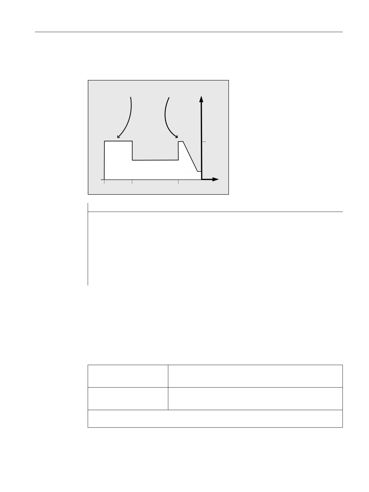
Tool offsets
11.2 Additive offsets
Example
The same cutting edge is used for two bearing seats:
/RFDWLRQ RI XVH
/RFDWLRQ RI XVH
;
' '/
'
=
Program code
Comment
N110 T7 D7
; The revolver is positioned to location 7. D7 and DL=1
are activated and moved through in the next block.
N120 G0 X10 Z1
N130 G1 Z-6
N140 G0 DL=2 Z-14
; DL=2 is activated in addition to D7 and is moved through
in the next block.
N150 G1 Z-21
N160 G0 X200 Z200
; Approach tool change point.
11.2.2
Specify wear and setup values ($TC_SCPxy[t,d], $TC_ECPxy[t,d])
Wear and setting-up values can be read and written to using system variables. The logic is
based on the logic of the corresponding system variables for tools and tool noses.
System variables
$TC_SCPxy[<t>,<d>]:
Wear values that are assigned to the particular geometry parameters
via xy, whereby x corresponds to the number of the wear value and y
establishes the reference to the geometry parameter.
$TC_ECPxy[<t>,<d>]:
Setting-up values that are assigned to the particular geometry param-
eter via xy, whereby x corresponds to the number of the setting-up
value and y establishes the reference to the geometry parameter.
<t>: T number of the tool
<d>: D number of the tool cutting edge
Job Planning
Programming Manual, 12/2018, A5E40869460B AB
403

Tool offsets
11.2 Additive offsets
Note
The defined wear and setup values are added to the geometry parameters and the other offset
parameters (D numbers).
Example
The wear value of length 1 is set to the value of 1.0 for the cutting edge <d> of tool <t>.
Parameter: $TC_DP3 (length 1, with turning tools)
Wear values: $TC_SCP13 to $TC_SCP63
Setup values: $TC_ECP13 to $TC_ECP63
$TC_SCP43 [<t>,<d>] = 1.0
11.2.3
Delete additive offsets (DELDL)
The DELDL command deletes the additive offsets for the cutting edge of a tool (to release
memory space). Both the defined wear values and the setup values are deleted.
Syntax
DELDL[<t>,<d>]
DELDL[<t>]
DELDL
<Status>=DELDL[<t>,<d>]
Meaning
DELDL:
Command to delete additive offsets
<t>:
T number of the tool
<d>:
D number of the tool cutting edge
DELDL[<t>,<d>]:
All additive offsets of the cutting edges <d> of the tool <t> are deleted.
DELDL[<t>]:
All additive offsets of all cutting edges of tool <t> are deleted.
DELDL:
All additive offsets of all cutting edges of all tools of the TO unit are deleted
(for the channel in which the command is programmed).
<Status>:
Delete status
Value:
Meaning:
0
Deletion was successfully completed.
-
Offsets have not been deleted (if the parameter settings specify ex-
actly one tool edge), or not deleted completely (if the parameter
settings specify several cutting edges).
Job Planning
404
Programming Manual, 12/2018, A5E40869460B AB
Tool offsets
11.2 Additive offsets
Note
Wear and setting-up values of active tools cannot be deleted (essentially the same as the
delete behavior of D or tool data).
Job Planning
Programming Manual, 12/2018, A5E40869460B AB
405

Tool offsets
11.3 Special handling of tool offsets
11.3
Special handling of tool offsets
The evaluation of the sign for tool length and wear can be controlled using setting data
SD42900 to SD42960.
The same applies to the behavior of the wear components when mirroring geometry axes or
changing the machining plane, and also to temperature compensation in tool direction.
Wear values:
If reference is made to wear values in the following, then this should be understood as the sum
of the actual wear values ($TC_DP12 to $TC_DP20) and the sum offsets with the wear values
($SCPX3 to $SCPX11) and setting-up values ($ECPX3 to $ECPX11).
For more information about summed offsets, refer to:
References:
Function Manual, Tool Management
Setting data
SD42900 $SC_MIRROR_TOOL_LENGTH
Mirroring of tool-length components and compo-
nents of the tool base dimension.
SD42910 $SC_MIRROR_TOOL_WEAR
Mirroring of wear values of the tool-length compo-
nents.
SD42920 $SC_WEAR_SIGN_CUTPOS
Evaluating the sign of the wear components as a
function of the cutting edge position.
SD42930 $SC_WEAR_SIGN
Inverts the sign of wear dimensions.
SD42935 $SC_WEAR_TRANSFORM
Transformation of wear values.
SD42940 $SC_TOOL_LENGTH_CONST
Assignment of tool length components to geome-
try axes.
SD42950 $SC_TOOL_LENGTH_TYPE
Assignment of the tool length components inde-
pendent of tool type.
SD42960 $SC_TOOL_TEMP_COMP
Temperature compensation value in tool direction.
Also operative when tool orientation is program-
med.
References
Function Manual Basic Functions; Tool Offset (W1)
Further information
Activation of modified setting data
When the setting data described above is modified, the tool components are not reevaluated
until the next time a tool edge is selected. If a tool is already active and the data of this tool is
to be reevaluated, the tool must be selected again.
Job Planning
406
Programming Manual, 12/2018, A5E40869460B AB
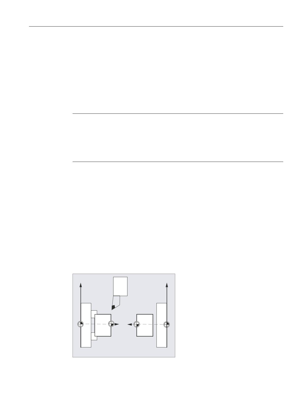
Tool offsets
11.3 Special handling of tool offsets
The same applies in the event that the resulting tool length is modified due to a change in the
mirroring status of an axis. The tool must be selected again after the mirror command, in order
to activate the modified tool-length components.
Orientable toolholders and new setting data
Setting data SD42900 to SD42940 has no effect on the components of an active toolholder
with orientation capability. However, the calculation with an orientable toolholder always allows
for a tool with its total resulting length (tool length + wear + tool base dimension). All
modifications initiated by the setting data are included in the calculation of the resulting total
length, i.e. vectors of the orientable toolholder are independent of the machining plane.
Note
When orientable toolholders are used, it is frequently practical to define all tools for a non-
mirrored basic system, even those which are only used for mirrored machining. When
machining with mirrored axes, the toolholder is then rotated such that the actual position of
the tool is described correctly. All tool-length components then automatically act in the correct
direction, dispensing with the need for control of individual component evaluation via setting
data, depending on the mirroring status of individual axes.
Further application options
The use of orientable toolholder functionality can also be useful if there is no physical option
of turning tools on the machine, even though tools with different orientations are permanently
installed. Tool dimensioning can then be performed uniformly in a basic orientation, where the
dimensions relevant for machining are calculated according to the rotations of a virtual
toolholder.
11.3.1
Mirroring of tool lengths
When setting data SD42900 $SC_MIRROR_TOOL_LENGTH and
SD42910 $SC_MIRROR_TOOL_WEAR are not set to zero, then you can mirror the tool length
components and components of the basis dimensions with wear values and their associated
axes.
;
'
;
=
=
0
:
:
0
:&6
:&6
' ZLWK 6/
' ZLWK 6/
Job Planning
Programming Manual, 12/2018, A5E40869460B AB
407

Tool offsets
11.3 Special handling of tool offsets
SD42900 $SC_MIRROR_TOOL_LENGTH
Setting data not equal to zero:
The tool length components ($TC_DP3, $TC_DP4 and $TC_DP5) and the components of the
basis dimensions ($TC_DP21, $TC_DP22 and $TC_DP23) are mirrored against their
associated axes, also mirrored - by inverting the sign.
The wear values are not mirrored. If these are also be be mirrored, then setting data
SD42910 $SC_MIRROR_TOOL_WEAR must be set.
SD42910 $SC_MIRROR_TOOL_WEAR
Setting data not equal to zero:
The wear values of the tool length components - whose associated axes are mirrored - are
also mirrored by inverting the sign.
11.3.2
Wear sign evaluation
When setting data SD42920 $SC_WEAR_SIGN_CUTPOS and SD42930 $SC_WEAR_SIGN
are set not equal to zero, then you can invert the sign evaluation of the wear components.
SD42920 $SC_WEAR_SIGN_CUTPOS
Setting data not equal to zero:
For tools with the relevant cutting edge position (turning and grinding tools, tool types 400),
then the sign evaluation of the wear components in the machining plane depends on the cutting
edge position. This setting data is of no significance for tool types without relevant cutting edge
position.
In the following table, the dimensions, whose sign is inverted using SD42920 (not equal to
zero), are designed using an X:
Cutting edge position
Length 1
Length 2
1
2
X
3
X
X
4
X
5
6
7
X
8
X
9
Note
The sign evaluation using SD42920 and SD42910 are independent of one another. If, for
example, the sign of a dimension is changed using both setting data, then the resulting sign
remains unchanged.
Job Planning
408
Programming Manual, 12/2018, A5E40869460B AB

Tool offsets
11.3 Special handling of tool offsets
SD42930 $SC_WEAR_SIGN
Setting data not equal to zero:
Inverts the sign of all wear dimensions. This affects both the tool length and other variables
such as tool radius, rounding radius, etc.
If a positive wear dimension is entered, the tool becomes "shorter" and "thinner", refer to
Chapter "tool offset, special handling", activating changed setting data".
11.3.3
Coordinate system of the active machining operation (TOWSTD, TOWMCS,
TOWWCS, TOWBCS, TOWTCS, TOWKCS)
Depending on the kinematics of the machine or the availability of an orientable tool carrier, the
wear values measured in one of these coordinate systems are converted or transformed to a
suitable coordinate system.
Coordinate systems of active machining operation
The following coordinate systems produce tool length offsets which the tool length wear
component incorporates in an active tool via the corresponding G command of Group 56:
● Machine coordinate system (MCS)
● Basic coordinate system (BCS)
● Workpiece coordinate system (WCS)
● Tool coordinate system (TCS)
● Tool coordinate system of kinematic transformation (KCS)
Syntax
TOWSTD
TOWMCS
TOWWCS
TOWBCS
TOWTCS
TOWKCS
Meaning
TOWSTD:
Initial setting value for offsets in tool length wear value
TOWMCS:
Offsets in tool length in MCS
TOWWCS:
Offsets in tool length in WCS
TOWBCS:
Offsets in tool length in BCS
TOWTCS:
Offsets in tool length at tool carrier reference point (orientable tool carrier)
TOWKCS:
Compensations of tool length for tool head (kinematic transformation)
Job Planning
Programming Manual, 12/2018, A5E40869460B AB
409

Tool offsets
11.3 Special handling of tool offsets
Further information
Distinguishing features
The most important distinguishing features are shown in the following table:
G command
Wear value
Active orientable tool carrier
TOWSTD:
Initial value, tool length
Wear values are subject to rotation.
TOWMCS:
Wear value in MCS. TOWMCS is iden-
It only rotates the vector of the resul-
tical to TOWSTD if a tool carrier that
tant tool length without taking into
can be orientated is not active.
account the wear.
TOWWCS:
The wear value is converted to the
The tool vector is calculated as for
MCS in the WCS.
TOWMCS without taking into account
the wear.
TOWBCS:
The wear value is converted to the
The tool vector is calculated as for
MCS in the BCS.
TOWMCS without taking into account
the wear.
TOWTCS:
The wear value is converted to the
The tool vector is calculated as for
MCS in the workpiece coordinate sys-
TOWMCS without taking into account
tem.
the wear.
TOWWCS, TOWBCS, TOWTCS: The wear vector is added to the tool vector.
Linear transformation
The tool length can be defined meaningfully in the MCS only if the MCS is generated by linear
transformation from the BCS.
Non-linear transformation
For example, if with TRANSMIT a non-linear transformation is active, then when specifying
the MCS as requested coordinate system, BCS is automatically used.
No kinematic transformation and no orientable tool carrier
If neither a kinematic transformation nor an orientable tool carrier is active, then all the other
four coordinate systems (except for the WCS) are combined. It is then only the WCS, which
is different to the other systems. Since only tool lengths need to be evaluated, translations
between the coordinate systems are irrelevant.
References:
For more information on tool compensation, see:
Function Manual Basic Functions; Tool Offset (W1)
Inclusion of wear values in calculation
The setting data SD42935 $SC_WEAR_TRANSFORM defines which of the three wear
components:
● Wear
● Total offsets fine
● Total offsets coarse
Job Planning
410
Programming Manual, 12/2018, A5E40869460B AB
Tool offsets
11.3 Special handling of tool offsets
should be subject to a rotation using adapter transformation or a tool carrier that can be
orientated if one of the following G commands is active:
● TOWSTD
Basic position. For corrections in the tool length.
● TOWMCS
Wear values in the machine coordinate system (MCS).
● TOWWCS
Wear values in the workpiece coordinate system (WCS).
● TOWBCS
Wear values in the basic coordinate system (BCS).
● TOWTCS
Wear values in the tool coordinate system at the tool carrier fixture (T tool carrier reference).
● TOWKCS
Wear values in the coordinate system of the tool head for kinematic transformation.
Note
Evaluation of individual wear components (assignment to geometry axes, sign evaluation)
is influenced by the following factors:
● Active plane
● Adapter transformation
● Setting data:
- SD42910 $SC_MIRROR_TOOL_WEAR
- SD42920 $SC_WEAR_SIGN_CUTPOS
- SD42930 $SC_WEAR_SIGN
- SD42940 $SC_TOOL_LENGTH_CONST
- SD42950 $SC_TOOL_LENGTH_TYPE
11.3.4
Tool length and plane change
When setting data SD42940 $SC_TOOL_LENGTH_CONST is set not equal to zero, then you
can assign the tool length components - such as lengths, wear and basic dimension - to the
geometry axes for turning and grinding tools when changing the plane.
SD42940 $SC_TOOL_LENGTH_CONST
Setting data not equal to zero:
The assignment of tool length components (length, wear and tool base dimension) to geometry
axes does not change when the machining plane is changed (G17 - G19).
The following table shows the assignment of tool length components to geometry axes for
turning and grinding tools (tool types 400 to 599):
Content
Length 1
Length 2
Length 3
17
Y
X
Z
*)
X
Z
Y
Job Planning
Programming Manual, 12/2018, A5E40869460B AB
411

Tool offsets
11.3 Special handling of tool offsets
19
Z
Y
X
-17
X
Y
Z
-18
Z
X
Y
-19
Y
Z
X
*)
Each value not equal to 0, which is not equal to one of the six listed values, is evaluated as value 18.
The following table shows the assignment of tool length components to geometry axes for all
other tools (tool types < 400 or > 599):
Operating plane
Length 1
Length 2
Length 3
*)
Z
Y
X
18
Y
X
Z
19
X
Z
Y
-17
Z
X
Y
-18
Y
Z
X
-19
X
Y
Z
*)
Each value not equal to 0, which is not equal to one of the six listed values, is evaluated as value 17.
Note
For representation in tables, it is assumed that geometry axes up to 3 are designated with X,
Y, Z. The axis order and not the axis identifier determines the assignment between a
compensation and an axis.
Job Planning
412
Programming Manual, 12/2018, A5E40869460B AB
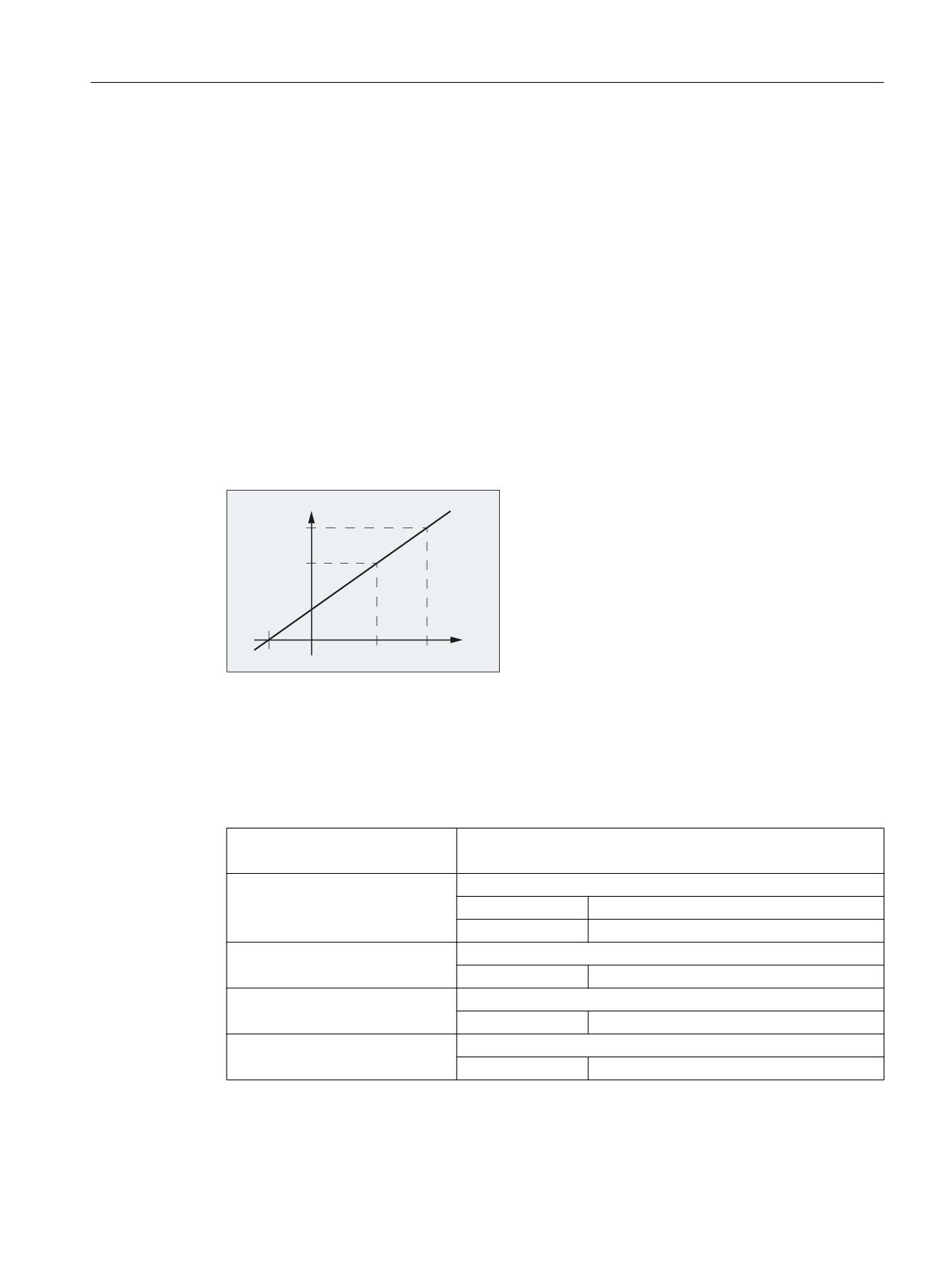
Tool offsets
11.4 Online tool offset
11.4
Online tool offset
11.4.1
Defining a polynomial function (FCTDEF)
Certain dressing strategies (e.g. dressing roller) are characterized by the fact that the grinding
wheel radius is continuously (linearly) reduced as the dressing roller is fed in. This strategy
requires a linear function between infeed of the dressing roller and writing the wear value of
each length. The linear function is defined using the predefined procedure FCTDEF(...) for up
to third order polynomial functions.
Straight line equation
y = f(x) = a0 + a1*x1
a1: Gradient of the straight line, with a1= Δx / Δy
a0: Shift of the straight line along the X axis with a0 = -a1 * XV
<
˂\
˂[
;
;9
Syntax
FCTDEF(<Func>,<LLimit>,<ULimit>,<a0>,<a1>,<a2>,<a3>)
Meaning
FCTDEF(...):
Defining a polynomial function for PUTFTOCF(...):
y = f(x) = a0 + a1*x + a2*x2 + a3*x3
<Func>:
Function number
Data type:
INT
Range of values:
1, 2, 3
<LLimit>:
Lower limit value
Data type:
REAL
<ULimit>:
Upper limit value
Data type:
REAL
<a0>,<a1>,<a2>,<a3>:
Coefficients of polynomial function
Data type:
REAL
Job Planning
Programming Manual, 12/2018, A5E40869460B AB
413

Tool offsets
11.4 Online tool offset
Example
Definitions
● Function number: 1
● Lower and upper limit value: -100, 100
● Gradient of the characteristic: a1 = 1
● The operating point should be located at the center of the characteristic. Based on the
setpoint position of axis XA in the WCS at the instant that the function is defined in the NC
program, the characteristic must be shifted in the negative Y direction: a0 = -a1 * XAD = -1
* $AA_IW
● a2 = a3 = 0
Characteristic
<
8/
;$'
;$
//
UL
Upper limit value
LL
Lower limit value
XAD
Setpoint of axis XA at the time that the function is defined in the NC program
Programming
Program code
Comment
FCTDEF(1,-100,100,-$AA_IW[XA],1)
; Function definition
11.4.2
Write online tool offset continuously (PUTFTOCF)
Using the predefined procedure PUTFTOCF(...), an online tool offset is executed based on a
polynomial function previously defined with FCTDEF(...) (Page 413).
Note
The online tool offset can also be realized using a synchronized action.
For further information, see Function Manual Synchronized Actions.
Job Planning
414
Programming Manual, 12/2018, A5E40869460B AB

Tool offsets
11.4 Online tool offset
Syntax
PUTFTOCF(<Func>,<RefVal>,<ToolPar>,<Chan>,<Sp>)
Meaning
PUTFTOCF(...):
Write online tool offset, continuously block-by-block using the polynomial function
defined with FCTDEF(...)
<Func>:
Function number, defined in the function definition with FCTDEF(...)
Data type:
INT
Range of val-
1, 2, 3
ues:
<RefVal>:
Reference value, from which the offset is to be derived (e.g. setpoint of an axis).
Data type:
VAR REAL
<ToolPar>:
Number of the wear parameter (length 1, 2 or 3) in which the offset value is to be
included.
Data type:
INT
<Chan>:
Number of the channel in which the online tool offset is to take effect.
Note:
Only required if the offset is not to take effect in the active channel.
Data type:
INT
<Sp>:
Number of the spindle for which the online tool offset is to take effect.
Note:
Only required if the offset is to be applied to a non-active grinding wheel rather
than the active tool that is currently in use.
Data type:
INT
11.4.3
Write online tool offset, discrete (PUTFTOC)
Function
Using the predefined procedurePUTFTOC(...), an online tool offset is executed based on a
fixed offset value.
Syntax
PUTFTOC(<CorrVal>,<ToolPar>,<Chan>,<Sp>)
Meaning
PUTFTOC(...):
Write online tool offset
<CorrVal>:
Offset value, which is added to the wear parameter.
Data type:
REAL
<ToolPar>:
Number of the wear parameter (length 1, 2 or 3) in which the offset value is to be
included.
Data type:
INT
Job Planning
Programming Manual, 12/2018, A5E40869460B AB
415

Tool offsets
11.4 Online tool offset
<Chan>:
Number of the channel in which the online tool offset is to take effect.
Note:
Only required if the offset is not to take effect in the active channel.
Data type:
INT
<Sp>:
Number of the spindle for which the online tool offset is to take effect.
Note:
Only required if the offset is to be applied to a non-active grinding wheel rather
than the active tool that is currently in use.
Data type:
INT
11.4.4
Activate/deactivate online tool offset (FTOCON/FTOCOF)
The online tool offset is activated or deactivated using the G commands FTOCON and
FTOCOF.
Syntax
FTOCON
FTOCOF
Meaning
FTOCON:
Activate online tool offset
The command must be programmed in the channel in which the online tool offset
is to be activated.
FTOCOF:
Deactivate online tool offset
The command must be programmed in the channel in which the online tool offset
is to be deactivated.
Note:
On FTOCOF, the axis does not move further out for the tool offset. However, the
value calculated with PUTFTOC/PUTFTOCF remains in the cutting-specific offset
data.
To finally deactivate the online tool offset, the tool (T...) must again be selected/
deselected after FTOCOF.
Job Planning
416
Programming Manual, 12/2018, A5E40869460B AB

Tool offsets
11.5 3D tool radius compensation
11.5
3D tool radius compensation
11.5.1
Selecting 3D tool radius compensation for 3D circumferential milling (CUT3DC,
CUT3DCD, ISD)
The 3D tool radius compensation (3D TRC) for the 3D circumferential milling without taking
limitation surfaces into account is selected with the modally effective G command CUT3DC or
CUT3DCD.
The actual activation is performed with G41 or G42 The tool radius compensation is
deactivated with G40.
Syntax
G41/G42 ORIC/ORID ISD=... CUT3DC/CUT3DCD CDOF2 X... Y... Z...
G40 X... Y... Z...
Meaning
CUT3DC:
3D TRC for circumferential milling (only when 5-axis transforma-
tion is active)
CUT3DCD:
3D TRC for circumferential milling referred to a differential tool
(only when 5-axis transformation is active)
The radius difference is specified by the tool parameter
$TC_DP15.
G41/G42 X... Y... Z... :
Activate tool radius compensation
G41:
Tool radius compensation left of the contour
G42:
Tool radius compensation right of the contour
Note:
The activation must be performed in a linear block (G0/G1).
CDOF2:
Deactivate collision detection for 3D circumferential milling
ORIC/ORID:
The behavior for orientation changes at outside corners is speci-
fied via the G commands ORIC and ORID.
ORIC:
Orientation changes at outside corners are superim-
posed on the circle block to be inserted.
ORID:
Orientation changes at outside corners are executed
before the circle block to be inserted.
ISD=<Value>:
With the ISD address, the insertion depth of the tool can be
changed for circumferential milling and active 3D tool radius com-
pensation.
<Value>:
Length of the insertion depth
G40 X... Y... Z... :
Deactivate tool radius compensation
Note:
The deactivation must be performed in a linear block (G0/G1) with
geometry axis movements.
Job Planning
Programming Manual, 12/2018, A5E40869460B AB
417
Tool offsets
11.5 3D tool radius compensation
Note
The G commands for selecting the 3D TRC are evaluated in the approach block, i.e. typically
in the block that contains G41 or G42.
G41 or G42 can also be programmed in blocks without traversing movement in geometry axes
relevant for the compensation. In this case, the approach block is the first traversing block
following such a block.
A change of the 3D TRC variant with active tool radius compensation is ignored without alarm.
Example
Program code
Comment
; Definition of tool D1:
$TC_DP1[1,1]=120
; Type (end mill)
$TC_DP3[1,1]=20
; Length compensation vector
$TC_DP6[1,1]=8
; Radius
N10 X0 Y0 Z0 T1 D1 F12000
; Selection of the tool.
N20 TRAORI(1)
; Activation of the transformation.
N30 G42 ORIC ISD=10 CUT3DC G64 X30
; Activation of the 3D circumferential milling,
; continuous orientation changes at outside corners,
; insertion depth: 10 mm
N40 ORIWKS A30 B15
; Orientation change at a corner through specification of axis po-
sitions.
N50 Y20 A3=1 C3=1
; Traversing block with orientation change,
; specification of the orientation with direction vector.
N60 X50 Y30
; Traversing block with constant orientation.
N70 Y50 A3=0.5 B3=1 C3=5
; Traversing block with orientation change.
N80 M63
; Block without traversing information.
N90 X0 ISD=20
; Traversing block with change of the insertion depth.
N100 G40 Y0
; Deactivation of the tool radius compensation.
N110 M30
Further information
Path and orientation
The type of circumferential milling used here is implemented by defining a path (guide line)
and the associated orientation. In this type of machining, the shape of the tool on the path is
not relevant. Only the radius at the tool intervention point is decisive.
Job Planning
418
Programming Manual, 12/2018, A5E40869460B AB
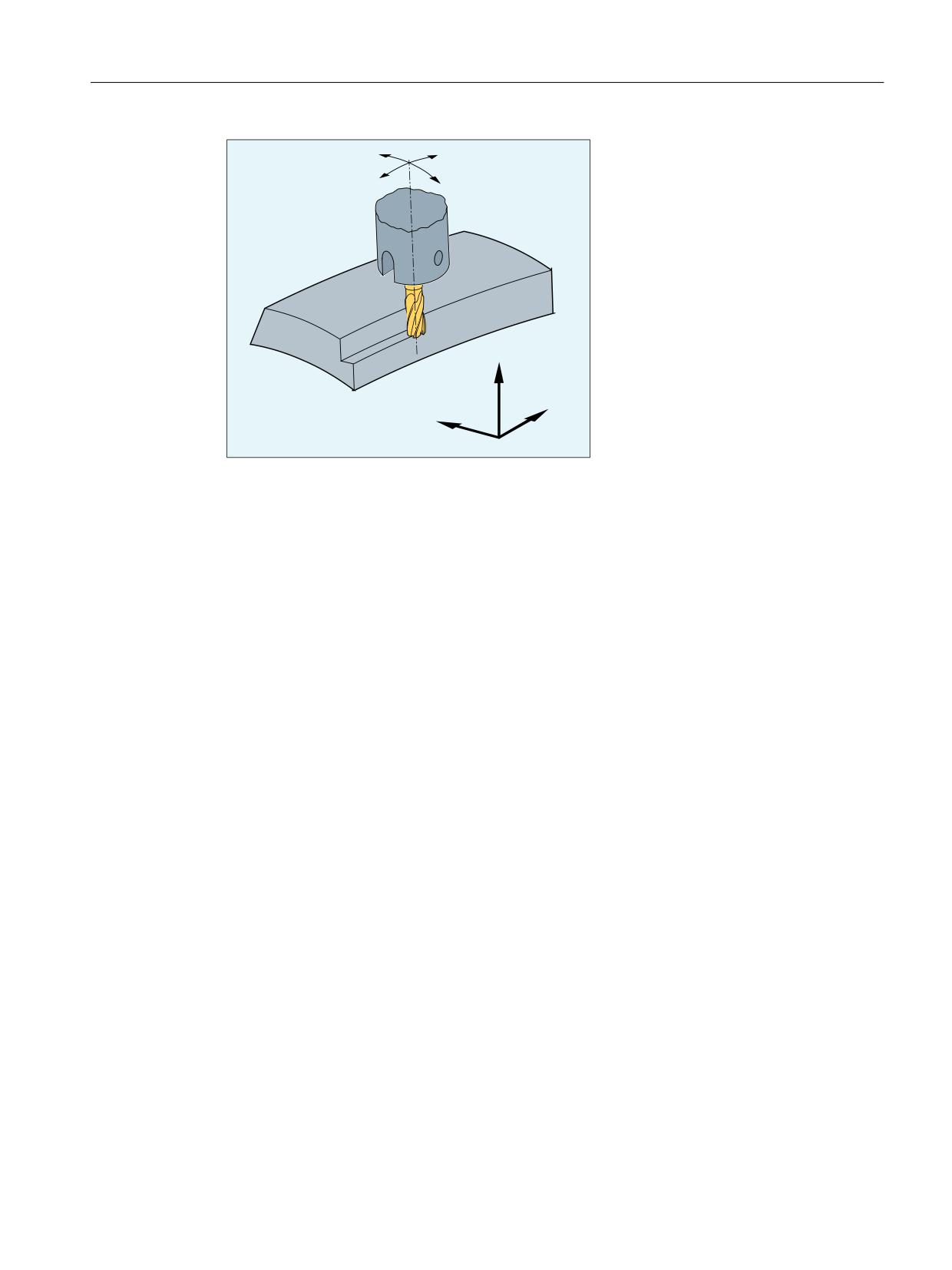
Tool offsets
11.5 3D tool radius compensation
$
%
=
;
<
Figure 11-1
Circumferential milling
Approach behavior
The approach behavior is always NORM for the 3D variant of the tool radius compensation.
Behavior at outside corners
The G commands of group 18 (corner behavior, tool offset) are evaluated at the outside corners
for circumferential milling with 3D TRC in the same way as for the conditions for the 2½D TRC:
● G450: Transition circle (tool travels round workpiece corners on a circular path)
In contrast to the solution for the 2½D TRC, the inserted contour element at an outside
corner is always a circle with a 0 radius, on which the tool radius compensation acts in the
same way as on any other programmed path. It is not possible to insert conics instead of
circles. In this case, the DISC address has no significance and is therefore not evaluated.
● G451: Intersection of equidistant paths (tool backs off from the workpiece corner)
The intersection is determined by extending the offset curves of the two participating blocks
and defining the intersection of the two blocks at the corner in the plane perpendicular to
the tool orientation.
The intersection procedure (G451) is not used when at least one block containing a change
to the tool orientation was inserted between the relevant traversing blocks. In this case, a circle
is always inserted at the corner.
Behavior for changes in orientation at outside corners
The ORIC and ORID G commands are used to determine whether changes in orientation
programmed between two blocks forming the corner are executed before the inserted circle
block (ORID) is processed or at the same time (ORIC).
Insertion depth
The insertion depth of the milling tool is the distance of the milling tool reference point from
the tip of the tool.
The milling tool reference point is the vertical projection of the milling tool machining point on
the programmed path to the longitudinal axis of the tool.
Job Planning
Programming Manual, 12/2018, A5E40869460B AB
419