SINUMERIK 840D sl/828D. Job Planning. Programming Manual (2010-2018) - page 5
Special motion commands
5.11 Programmable end of motion criteria (FINEA, COARSEA, IPOENDA, IPOBRKA, ADISPOSA)
SD43600 $SA_IPOBRAKE_BLOCK_EXCHANGE
IPOBRKA is deactivated for the corresponding access when an axis end-of-motion criterion
(FINEA, COARSEA
, IPOENDA ) is next programmed for the axis.
Additional block-change criterion: "Tolerance window" (ADISPOSA)
Using ADISPOSA, a tolerance window around the end of block (either as actual or setpoint
position) can be defined as additional block change criterion. Then, two conditions must be
fulfilled for the block change:
● Block-change criterion: "Braking ramp"
● Block-change criterion: "Tolerance window"
References
For further information about the block change criterion for positioning axes, see:
● Function Manual, Extended Functions; Positioning Axes (P2)
● Programming Manual, Fundamentals; Chapter "Feedrate control".
Job Planning
282
Programming Manual, 12/2018, A5E40869460B AB
Coordinate transformations (frames)
6
6.1
Coordinate transformation via frame variables
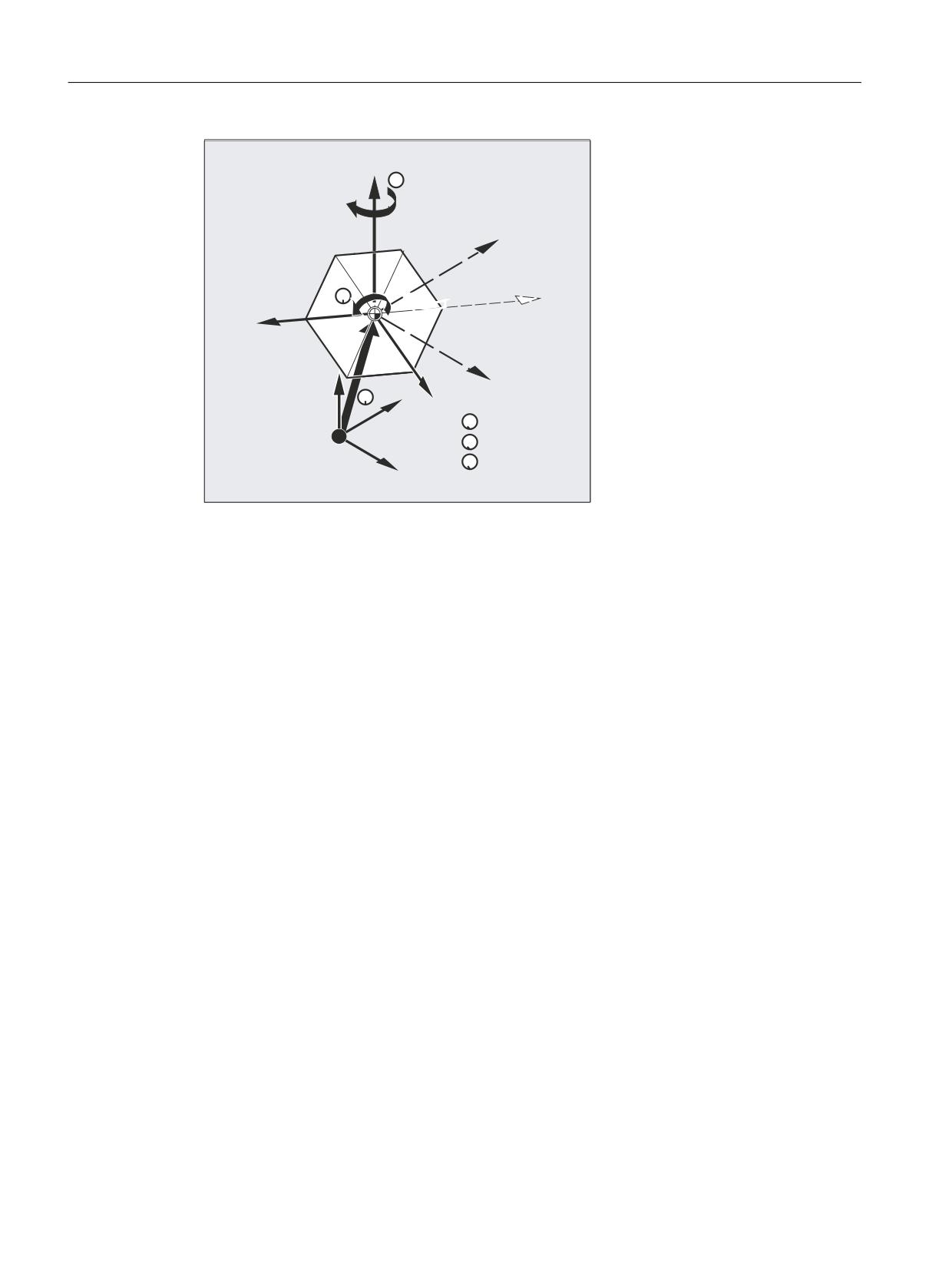
In addition to the commands such as ROT, AROT and SCALE described in the Fundamentals
Programming Manual, "Coordinate transformations (frames)" section, the workpiece
coordinate system (WCS) can also be transformed by the frame variables $P_...FR (data
storage frames) and $P_...FRAME (active frames).
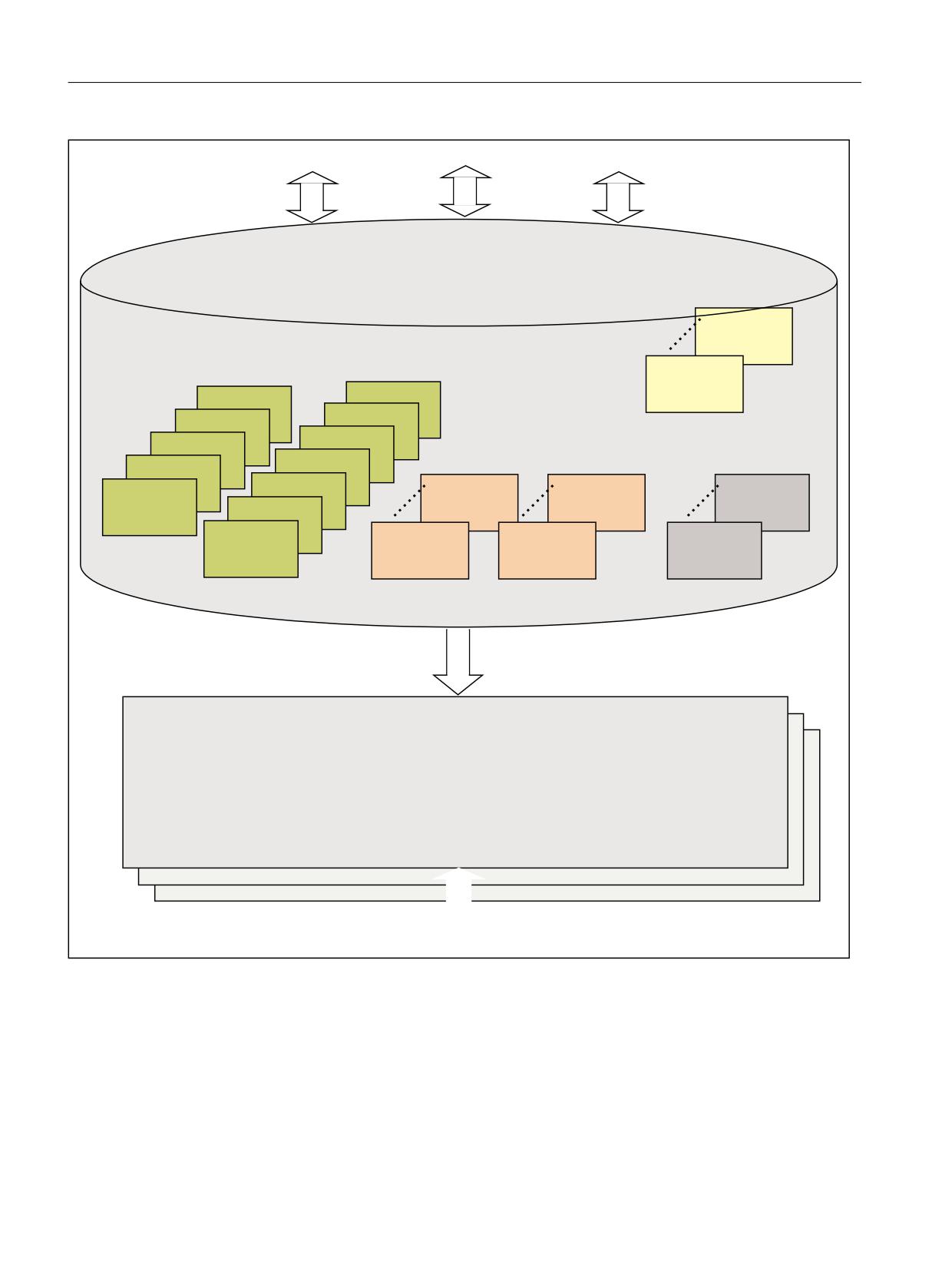
The following diagram provides an overview of structuring frame variables:
● Data management frames
● Active frames
● Active total frame: Chain of all active frames
● NCU global frames
● Channel-specific frames
Job Planning
Programming Manual, 12/2018, A5E40869460B AB
283
Coordinate transformations (frames)
6.1 Coordinate transformation via frame variables
3DUW SURJUDP
$UFKLYLQJ
8VHU LQWHUIDFH
*ULQGLQJ IUDPHV
1&8 RGHU &+$1
3B*)5>Q@
6\VWHP IUDPHV
3B*)5> @
&+$1
3B&<&)5
3B5(/)5
3B75$)5
3B,62 )5
3B:3)5
%DVLF IUDPHV
6HWWDEOH IUDPHV
3B,62 )5
3B722/)5
1&8
&+$1
1&8 RGHU &+$1
3B,62 )5
3B(;7)5
3B1&%)5>Q@
3B&+%)5>Q@
3B8,)5>Q@
3B,62 )5
3B6(7)5
3B3$57)5
3B1&%)5> @
3B&+%)5> @
3B8,)5> @
*
*
*
3,B6(78'7
*)5$0(
*)5$0(
5HVHW
$FWLYDWLRQ RI GDWD VWRUDJH IUDPHV WKURXJK
7UDQVIRUPDWLRQVZHFKVHO *(2$;
&KDQQHO
$FWLYH IUDPHV
3B$&7)5$0(
3B3$57)5$0( 3B6(7)5$0( 3B(;7)5$0(
DFWLYH FRPSOHWH IUDPH WKURXJK FKDLQLQJ
3B,62 )5$0(
3B,62 )5$0( 3B,62 )5$0(
RI DOO DFWLYH IUDPHV LQ WKH VSHFLILHG RUGHU
3B$&7%)5$0(
3B,)5$0( 3B*)5$0(
3B722/)5$0(
3B:3)5$0( 3B75$)5$0(
3B3)5$0( 3B,62 )5$0( 3B&<&)5$0(
3DUW SURJUDP
Figure 6-1
Overview of the frame variables
Job Planning
284
Programming Manual, 12/2018, A5E40869460B AB
Coordinate transformations (frames)
6.1 Coordinate transformation via frame variables
6.1.1
Predefined frame variable ($P_CHBFRAME, $P_IFRAME, $P_PFRAME,
$P_ACTFRAME)
Active: channel-specific base frames $P_CHBFRAME[ <n> ] ($P_BFRAME)
Note
The current base frame $P_BFRAME and the data storage base frame $P_UBFR are retained
for compatibility reasons.
● $P_BFRAME ≙ $P_CHBFRAME[0]
● $P_UBFR ≙ $P_CHBFR[0].
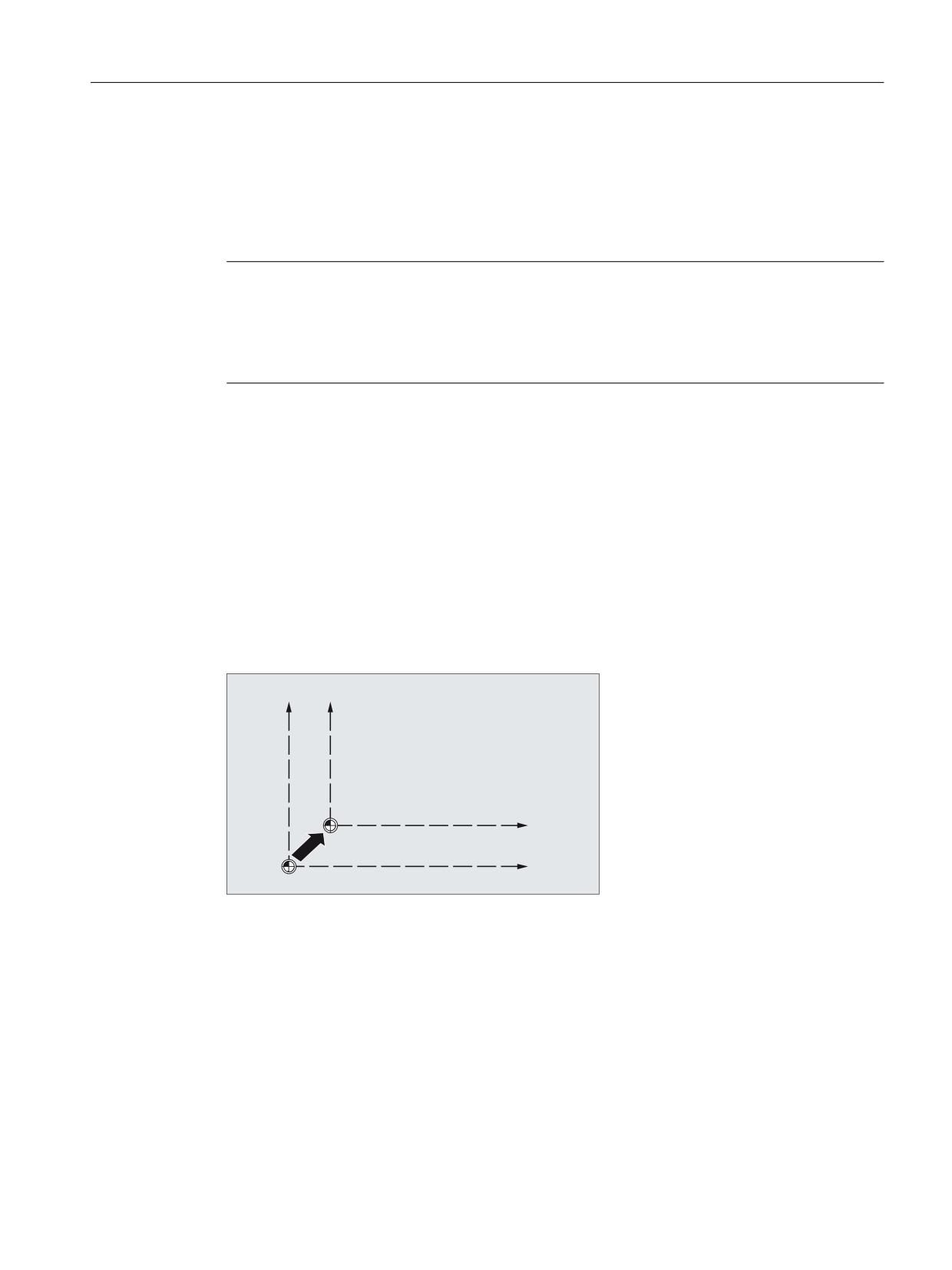
The frame variables $P_CHBFRAME[<n>] define the reference between the basic coordinate
system (BCS) and the basic origin system (BOS).
If the current channel-specific base frame $P_CHBFRAME[<n>] should be active immediately
in the NC program, the following possibilities are available.
● Commands:
- G500 (deactivate all settable frames, the base frames remain active)
- G54 to G599 (settable zero offsets)
● Assignment of a channel-specific base frames of the data storage to a current channel-
specific base frame:
$P_CHBFRAME[<n>] = $P_CHBFR[<m>]
=
=
%.6
%16
;
%16
3B$&7%)5$0(
;%.6
Active: Channel-specific settable frame $P_IFRAME
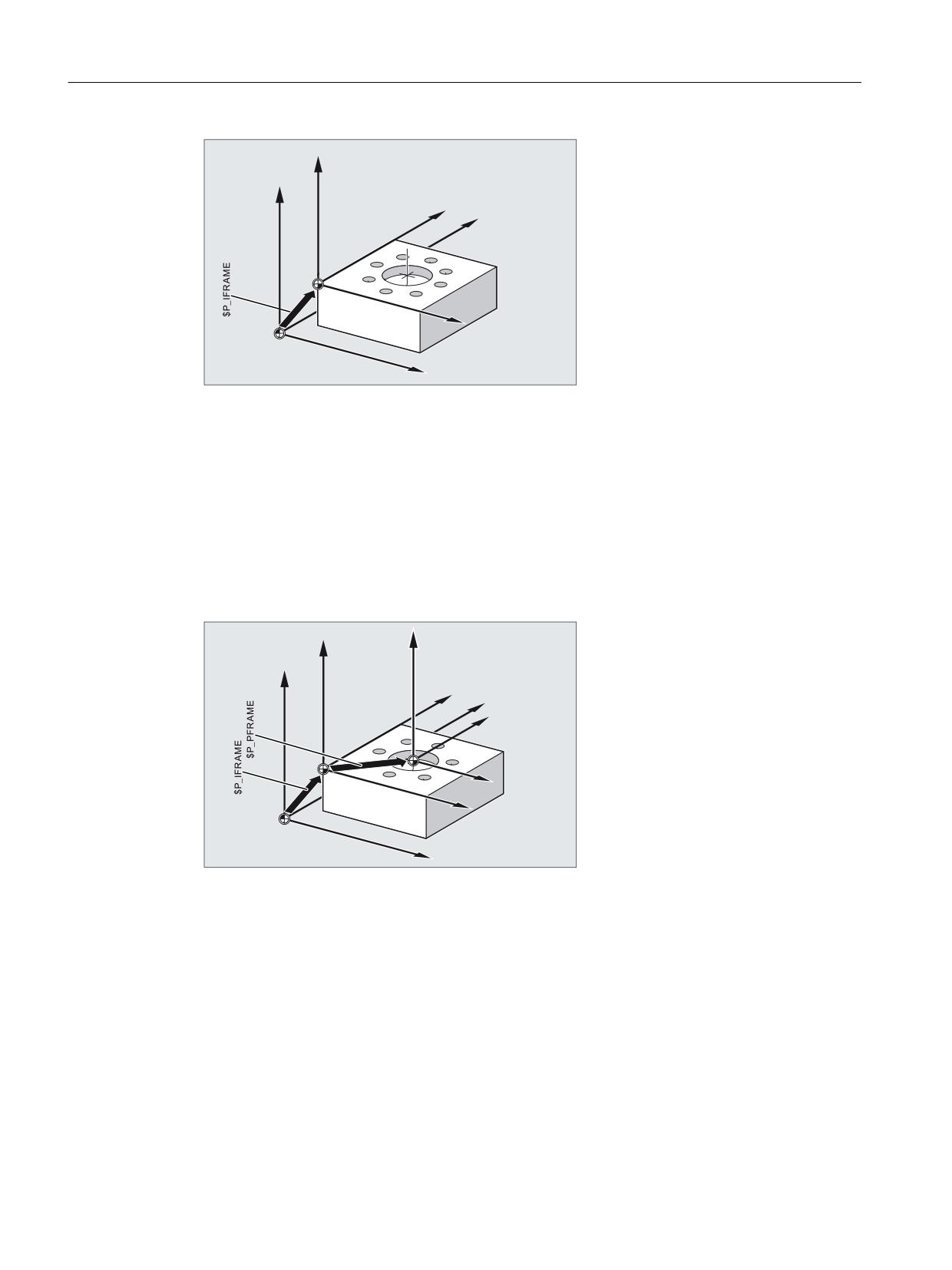
The frame variable $P_IFRAME defines the reference between the basic origin system (BOS)
and the settable zero system (SZS).
● $P_IFRAME corresponds to $P_UIFR[$P_IFRNUM]
● After G54 is programmed, for example, $P_IFRAME contains the translation, rotation,
scaling and mirroring defined by G54.
Job Planning
Programming Manual, 12/2018, A5E40869460B AB
285
Coordinate transformations (frames)
6.1 Coordinate transformation via frame variables
=
(16
=
%16
<
(16
<%16
;
(16
; %16
Active: Channel-specific programmable frame $P_PFRAME
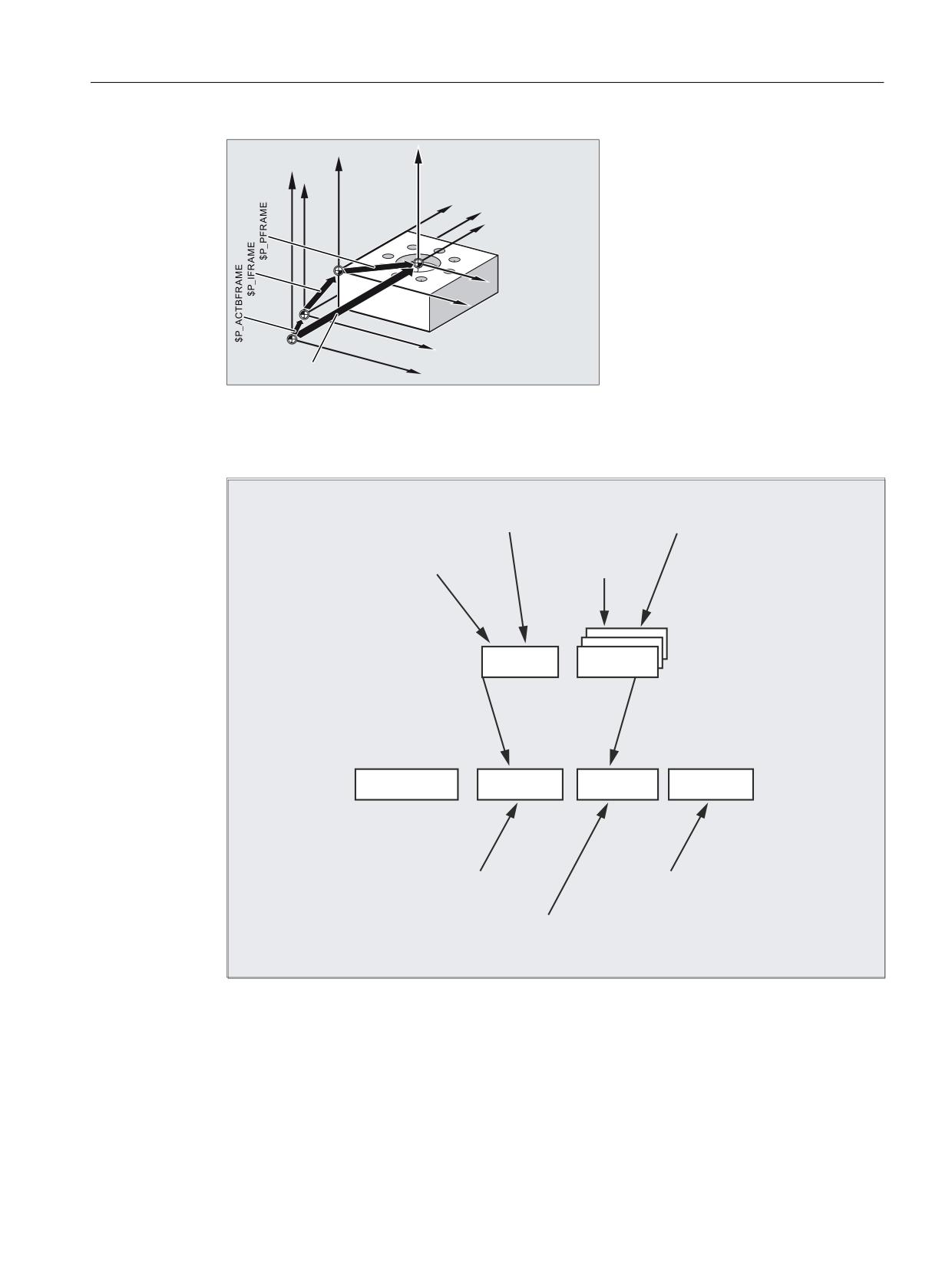
The $P_PFRAME frame variable defines the reference between the settable zero system
(SZS) and the workpiece coordinate system (WCS).
$P_PFRAME contains the resulting frame, that results
● From the programming of TRANS/ATRANS, ROT/AROT, SCALE/ASCALE, MIRROR/
AMIRROR or
● From the assignment of CTRANS, CROT, CMIRROR, CSCALE to the programmed FRAME
=
:.6
=
(16
=%16
<
(16
%16
<
<
:.6
;:
.6
; (16
; %16
Active: Total frame $P_ACTFRAME
The total frame active in the channel results from the chaining of all frames acting in the
channel.
$P_ACTFRAME =
$P_PARTFRAME : $P_SETFRAME : $P_EXTFRAME :
$P_ISO1FRAME : $P_ISO2FRAME : $P_ISO3FRAME :
$P_ACTBFRAME : $P_IFRAME : $P_GFRAME :
$P_TOOLFRAME : $P_WPFRAME : $P_TRAFRAME :
$P_PFRAME
: $P_ISO4FRAME : $P_CYCFRAME
$P_ACTFRAME describes the currently valid workpiece coordinate system.
Job Planning
286
Programming Manual, 12/2018, A5E40869460B AB
Coordinate transformations (frames)
6.1 Coordinate transformation via frame variables
=:.6
=
=%.6
(16
=%16
<(16
<%16
<.6
;:.6
;(16
;%16
;%.6
3B$&7)5$0(
Figure 6-2
Frame variable $P_ACTFRAME
If one of the following frames $P_BFRAME / $P_CHBFRAME[<n>], $P_IFRAME or
$P_PFRAME is changed, the current total frame $P_ACTFRAME is recalculated.
,QSXW IURP SURJUDP H J
,QSXW IURP SURJUDP H J
3B8%)5 &75$16 ;
3B8,)5>Q@ &75$16 ;
,QSXW IURP
,QSXW IURP
+0, 00&
+0, 00&
3B8%)5
3B8,)5>Q@
DFWLYDWHG YLD
*
*
*
3B$&7)5$0(
3B%)5$0(
3B,)5$0(
3B3)5$0(
,QSXW IURP SURJUDP H J
,QSXW IURP SURJUDP H J
3B%)5$0( &75$16 ;
3B3)5$0( &75$16 ;
RU 75$16 ;
,QSXW IURP SURJUDP H J
3B,)5$0( &75$16 ;
Basic frame and settable frame are effective after Reset if MD 20110 RESET_MODE_MASK
is set as follows:
Bit0=1, bit14=1 --> $P_UBFR (basic frame) acts
Bit0=1, bit5=1 --> $P_UIFR [$P_UIFRNUM](settable frame) acts
Job Planning
Programming Manual, 12/2018, A5E40869460B AB
287

Coordinate transformations (frames)
6.1 Coordinate transformation via frame variables
Data storage: channel-specific base frames $P_CHBFR[<n>]
The frame variables $P_CHBFR[<n>] read/write the base frames in the data storage. The data
storage frame is not immediately active in the channel when written. The written frame is
activated with:
● Channel reset and MD20110 $MC_RESET_MODE_MASK, Bit0 == 1 and Bit14 == 1
● Command G500, G54 ... G57, G505 ... G599 (activation/deactivation of base frames with
subsequent recalculation of the current total frames)
Data storage: Channel-specific settable frames $P_UIFR[<n>]
The frame variables $P_UIFR[<n>] read/write the settable base frames in the data storage.
The frame is not immediately active in the channel when written. The written frame in the
channel is calculated with:
● G500 command (deactivate all settable frames or zero offsets)
● G54 ... G57, G505 ... G599 command (activate a settable frame or zero offset)
Active settable frame
Data storage frame
(corresponds to command)
$P_IFRAME =
$P_UIFR[0]
G500
$P_UIFR[1]
G54
$P_UIFR[2]
G55
$P_UIFR[3]
G56
$P_UIFR[4]
G57
$P_UIFR[5]
G505
$P_UIFR[6]
G506
$P_UIFR[99]
G599
Job Planning
288
Programming Manual, 12/2018, A5E40869460B AB

Coordinate transformations (frames)
6.2 Value assignments to frames
6.2
Value assignments to frames
6.2.1
Assigning direct values (axis value, angle, scale)
You can directly assign values to frames or frame variables in the NC program.
Syntax
Syntax
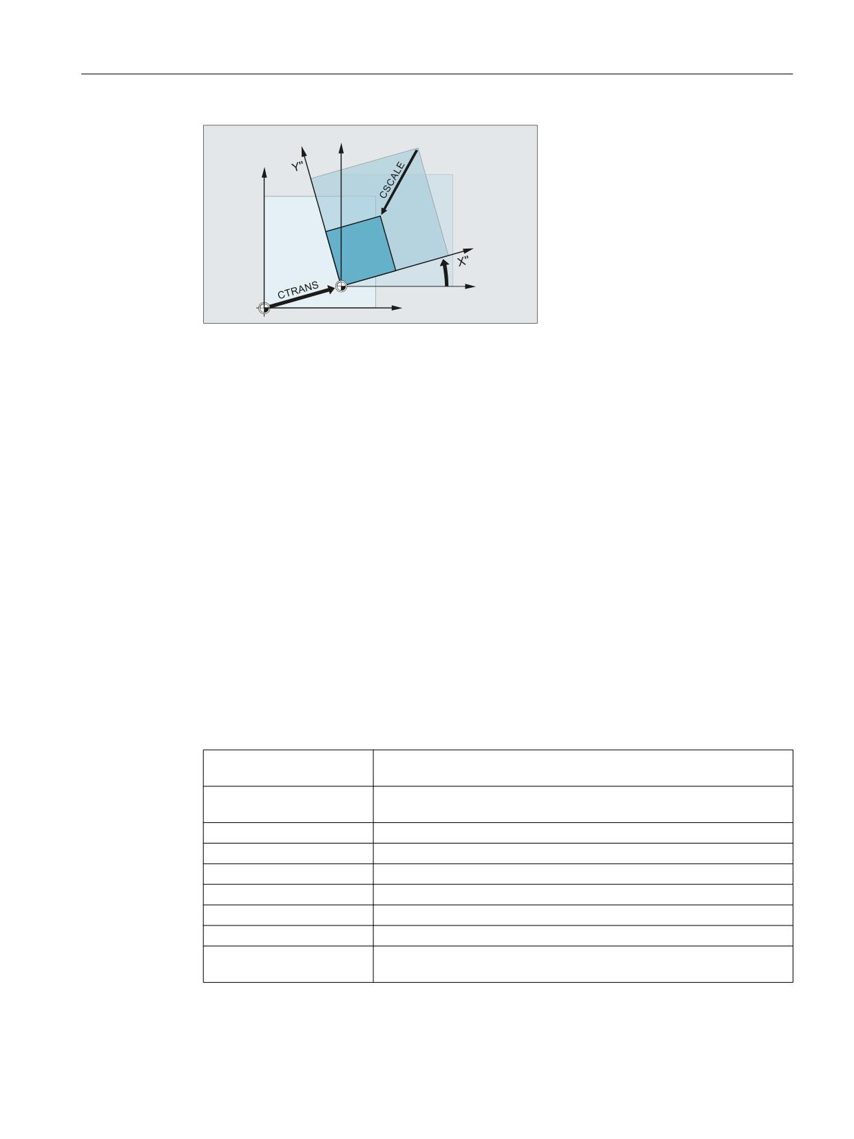
$P_PFRAME = CTRANS(X, <offset value>, Y, <offset value>, Z, <offset
value>, ...)
$P_PFRAME = ROT(X, <angle>, Y, <angle>, Z, <angle>, ...)
$P_UIFR[..] = CROT(X, <angle>, Y, <angle>, Z, <angle>, ...
$P_PFRAME = CSCALE(X, <scale>, Y, <scale>, Z, <scale>, ...)
$P_PFRAME = CMIRROR(X, Y, Z)
The syntax for $P_CHBFRAME[<n>] is identical to $P_PFRAME.
Meaning
CTRANS:
Translation of specified axes
CROT:
Rotation around specified axes
CSCALE:
Scale change on specified axes
CMIRROR:
Direction reversal on specified axis
X, Y, Z:
Offset value in the direction of the specified geometry axis
<offset value>:
Offset value
<angle>:
The angle with the rotation
<scale>:
Scale value
Examples
Value assignments to frame components of the current programmable frame
Value assignment to the translation, rotation and mirror frame components of the current
programmable frame:
$P_PFRAME = CTRANS(X,10,Y,20,Z,5) : CROT(Z,45) : CMIRROR(Y)
Job Planning
Programming Manual, 12/2018, A5E40869460B AB
289
Coordinate transformations (frames)
6.2 Value assignments to frames
=
<
<
<
;
=
;
<
&75$16
&527
&0,5525
;
Writing the rotation components of a frame
Assignment of values to all three axes of the rotation component of the settable data storage
frame $P_UIFR with CROT :
$P_UIFR[5] = CROT(X, 0, Y, 0, Z, 0)
Alternatively, the direct assignment of the individual values to the associated axis of the rotation
component of the data storage frame:
$P_UIFR[5, Y, RT]=0
$P_UIFR[5, X, RT]=0
$P_UIFR[5, Z, RT]=0
Description
The chaining operator : combines several operations on a frame with each other. The
operations are processed successively from left to right.
Example
Chained operations on $P_PFRAME with offset, rotation and scaling:
$P_PFRAME = CTRANS(...) : CROT(...) : CSCALE...
Job Planning
290
Programming Manual, 12/2018, A5E40869460B AB
Coordinate transformations (frames)
6.2 Value assignments to frames
<
<
&527
;
;
6.2.2
Reading and changing frame components (TR, FI, RT, SC, MI)
This feature allows you to access individual data of a frame, e.g. a specific offset value or angle
of rotation. You can modify these values or assign them to another variable.
Syntax
R10=$P_UIFR[$P_UIFNUM,X,RT]
Assign the angle of rotation RT around the X axis
from the currently valid settable zero offset $P_UIFR-
NUM to the variable R10.
R12=$P_UIFR[25,Z,TR]
Assign the offset value TR in Z from the data set of
set frame no. 25 to the variable R12.
R15=$P_PFRAME[Y,TR]
Assign the offset value TR in Y of the current pro-
grammable frame to the variable R15.
$P_PFRAME[X,TR] = 25
Modify the offset value TR in X of the current pro-
grammable frame. X25 applies immediately.
Meaning
$P_UIFRNUM:
This command automatically establishes the reference
to the currently valid settable zero offset.
P_UIFR[n,…,…] :
Specify the frame number n to access the settable
frame no. n.
Specify the component to be read or modified:
TR:
TR Translation
FI:
FI Translation Fine
RT:
RT Rotation
SC:
SC Scale scale modification
MI:
MI Mirroring
X, Y, Z:
The corresponding axis X, Y, Z is also specified (see
examples).
Job Planning
Programming Manual, 12/2018, A5E40869460B AB
291
Coordinate transformations (frames)
6.2 Value assignments to frames
Value range for RT rotation
Rotation around 1st geometry axis:
-180° to +180°
Rotation around 2nd geometry axis: -90° to +90°
Rotation around 3rd geometry axis:
-180° to +180°
Description
Calling frame
By specifying the system variable $P_UIFRNUM you can access the current zero offset set
with $P_UIFR or G54, G55, ...
($P_UIFRNUM contains the number of the currently set frame).
All other stored settable $P_UIFR frames are called up by specifying the appropriate number
$P_UIFR[n].
For predefined frame variables and user-defined frames, specify the name, e.g. $P_IFRAME.
Calling data
The axis name and the frame component of the value you want to access or modify are written
in square brackets, e.g. [X, RT] or [Z, MI].
6.2.3
Calculating with frames
A frame can be assigned to another frame or frames can be chained to each other in the NC
program.
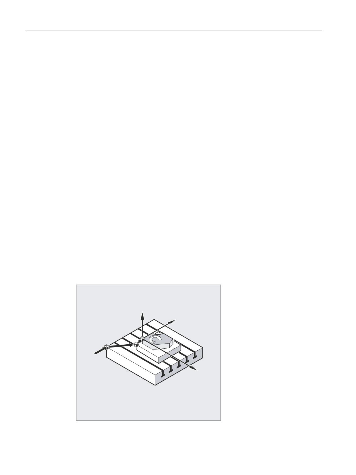
Frame chainings are suitable for the description of several workpieces, arranged on a pallet,
which are to be machined in the same process.
=
<
*
;
Job Planning
292
Programming Manual, 12/2018, A5E40869460B AB
Coordinate transformations (frames)
6.2 Value assignments to frames
The frame components can only contain intermediate values for the description of pallet tasks.
These are chained to generate various workpiece zeroes.
Examples
Assignments
Program code
Comment
DEF FRAME SETTING_1
; Definition of a local frame variable
SETTING_1 = CTRANS(X,10)
; Assignment of the function result to the frame
variable
$P_PFRAME = SETTING_1
; Assignment of the frame variable to the current
frame
DEF FRAME SETTING_4
; Definition of a local frame variable
SETTING_4 = $P_PFRAME
; Buffer the current frame in the frame variable
$P_PFRAME = SETTING_4
; Fetch the current frame from the frame variable
Chainings
The operator : chains frames with each other in the programmed sequence. The frame
components, such as offsets and rotations, are executed successively additive.
Program code
Comment
$P_IFRAME = $P_UIFR[15] :
; Assignment of the result frame from the chaining
$P_UIFR[16]
of the
; two settable data storage frames on the active
; settable total frame.
; Application example:
; $P_UIFR[15]: Offset
; $P_UIFR[16]: Rotation
$P_UIFR[3] = $P_UIFR[4] :
; Assignment of the result frame from the chaining
$P_UIFR[5]
of the
; two settable data storage frames on a
; different settable data storage frame
6.2.4
Definition of frame variables (DEF FRAME)
In addition to the predefined frame variables, user frame variables can also be defined. The
user-defined frame variables are user variables of type FRAME. The name of the frame can
be assigned freely in accordance with the rules for user variables.
The CTRANS, CROT, CSCALE and CMIRROR functions assign values to user-defined frame
variables.
Syntax
DEF FRAME <name>
Job Planning
Programming Manual, 12/2018, A5E40869460B AB
293
Coordinate transformations (frames)
6.2 Value assignments to frames
Meaning
DEF FRAME:
Define user variable of the type FRAME.
<name>:
Name of the frame variable
Example
Definition of a "PALETTE" frame variable and the assignment of offset and rotation values:
Program code
Comment
DEF FRAME PALETTE
; Define PALETTE frame variable
PALETTE = CTRANS(...) : CROT(...)
; Assignment of the result frame of the chaining
for
; offset and rotation on the PALETTE frame variable
Job Planning
294
Programming Manual, 12/2018, A5E40869460B AB
Coordinate transformations (frames)
6.3 Coarse and fine offsets (CTRANS, CFINE)
6.3
Coarse and fine offsets (CTRANS, CFINE)
Fine offset
A fine offset CFINE(...) can be applied to the following frames:
● Settable frames: $P_UIFR or $P_IFRAME
● Basic frames: $P_NCBFR[<n>], $P_CHBFR[<n>], $P_CHBFRAMES[<n>] or
$P_ACTBFRAME
● Programmable frame: $P_PFRAME
The fine offset of a frame is programmed with the CFINE(...) command.
Coarse offset
A coarse offset CTRANS(...) can be applied to all frames.
Total offset
The total offset results from the addition of the coarse and the fine offset.
Machine data
Enable of the fine offset
The fine offset is enabled with the machine data:
MD18600 $MN_MM_FRAME_FINE_TRANS = 1
Syntax
Fine offset
● Complete frame
- <frame> = CFINE(<K_1>,<value>)
- <frame> = CFINE(<K_1>,<value>, <K_2>, <value>)
- <frame> = CFINE(<K_1>,<value>, <K_2>, <value>, <K_3>, <value>)
● Frame component
- <frame>[<n>, <K_1>, FI] = <value>
Coarse offset
● Complete frame
- <frame> = CTRANS(<K_1>,<value>)
- <frame> = CTRANS(<K_1>,<value>, <K_2,<value>)
- <frame> = CTRANS(<K_1>,<value>, <K_2,<value>, <K_3,<value>)
● Frame component
- <frame>[<n>,<K_1>,TR] = <value>
Job Planning
Programming Manual, 12/2018, A5E40869460B AB
295
Coordinate transformations (frames)
6.3 Coarse and fine offsets (CTRANS, CFINE)
In particular for the programmable frame $P_PFRAME:
● TRANS <K_1> <value>
● TRANS <K_1> <value> <K_2> <value>
● TRANS <K_1> <value> <K_2> <value> <K_3> <value>
Meaning
<Frame>:
Frame, e.g. settable frame of the data storage $P_UIFR[<n>]
CFINE:
Fine offset, additive offset.
CTRANS:
Coarse offset, absolute offset.
TRANS:
Only programmable frame: Coarse offset, absolute offset.
<K_n>:
Coordinate axes X, Y, Z
<value>:
Offset value
Job Planning
296
Programming Manual, 12/2018, A5E40869460B AB
Coordinate transformations (frames)
6.4 External zero offset ($AA_ETRANS)
6.4
External zero offset ($AA_ETRANS)
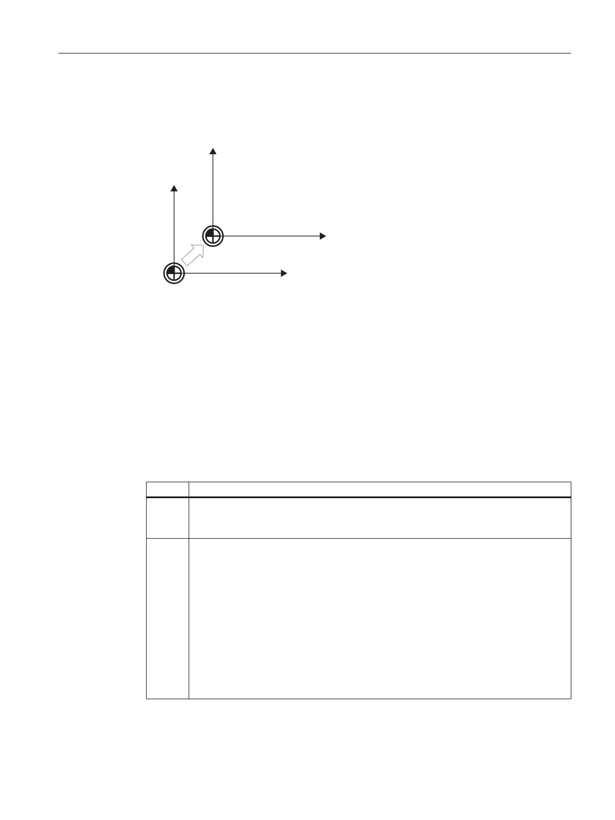
The external zero offset is a linear offset between the base coordinate system (BCS) and the
basic origin system (BOS).
]%16
]%.6
[%16
$$B(75$16 3B(;7)5$0(
[%.6
The external zero offset with $AA_ETRANS acts in two ways depending on the machine data
parameterization:
1. After activation by the NC/PLC interface signal, the system variable $AA_ETRANS acts
directly as offset value
2. After activation by the NC/PLC interface signal, the value of the system variable
$AA_ETRANS is transferred to the active system frames $P:EXTFRAME and the data
storage frame $P_EXTFR. The active total frame $P_ACTFRAME is then recalculated.
Machine data
In conjunction with the system variable $AA_ETRANS, a differentiation is made between two
procedures selected with the following machine data:
MD28082 $MC_MM_SYSTEM_FRAME_MASK,Bit1 = <value>
<value>
Meaning
0
Function: $AA_ETRANS[<axis>] written directly by PLC, HMI or NC program.
Enable for retraction of the zero offset for $AA_ETRANS[<axis>] in the next possible tra-
versing block: DB31, ... DBX3.0
1
Function: Activation of the active system frame $P:EXTFRAME and the data storage frame
$P_EXTFR
Enable for retraction of the zero offset for $AA_ETRANS[<axis>] by: DB31, ... DBX3.0. The
following is performed in the channel:
● Stop all traversal movements in the channel (other than command and PLC axes)
● Preprocessing stop with subsequent reorganization (STOPRE)
● Coarse offset of active frame $P_EXTFRAME[<axis>] = $AA_ETRANS[<axis>]
● Coarse offset of data storage frame $P_EXTFR[<axis>] = $AA_ETRANS[<axis>]
● Recalculation of the active total frame $P_ACTFRAME
● Retraction of the offset in the programmed axes.
● Continuation of the interrupted traversing motion or of the NC program
Job Planning
Programming Manual, 12/2018, A5E40869460B AB
297
Coordinate transformations (frames)
6.4 External zero offset ($AA_ETRANS)
Programming
● Syntax
$AA_ETRANS[<axis>] = <value>
● Meaning
$AA_ETRANS:
System variable for buffering the external zero offset
<axis>:
Channel axis
<value>:
Offset value
NC/PLC interface signal
DB31, ... DBX3.0 = 0 → 1 ⇒ $P_EXTFRAME[<axis>] = $P_EXTFR[<axis>] =
$AA_ETRANS[<axis>]
Job Planning
298
Programming Manual, 12/2018, A5E40869460B AB

Coordinate transformations (frames)
6.5 Set actual value with loss of the referencing status (PRESETON)
6.5
Set actual value with loss of the referencing status (PRESETON)
The PRESETON() procedure sets for one or more axes a new actual value in the machine
coordinate system (MCS). This corresponds to a zero offset of the MCS of the axis. This does
not cause the axis to be traversed.
PRESETON initiates a preprocessing stop with synchronization. The actual position is assigned
to the axis only at standstill.
If the axis for PRESETON is not assigned to the channel, the further procedure depends on the
axis-specific configuring of the axis replacement behavior:
MD30552 $MA_AUTO_GET_TYPE
Referencing status
By setting a new actual value in the machine coordinate system, the referencing status of the
machine axis is reset:
DB31, ... DBX60.4/.5 = 0 (referenced / synchronized measuring system 1/2)
For this reason it is recommended that PRESETON only be used for axes that do not require a
reference point.
To restore the original machine coordinate system, the measuring system of the machine axis
must be referenced again, e.g. through active referencing from the part program (G74).
CAUTION
Loss of the referencing status
The setting of a new actual value in the machine coordinate system with PRESETON resets
the referencing status of the machine axis to "not referenced / synchronized".
Programming
Syntax
PRESETON(<axis_1>, <value_1> [, <axis_2>, <value_2>, ... <axis_8>,
<value_8>])
Meaning
PRESETON:
Set actual value with loss of the referencing status
Preprocessing
yes
stop:
Alone in the block:
yes
<axis_x>:
Machine axis name
Type:
AXIS
Range of values:
Machine axis names defined in the channel
<value_x>:
New actual value of the machine axis in the machine coordinate system (MCS)
The input is made in the currently valid measuring system (inch/metric)
An active diameter programming (DIAMON) is considered
Type:
REAL
Job Planning
Programming Manual, 12/2018, A5E40869460B AB
299
Coordinate transformations (frames)
6.5 Set actual value with loss of the referencing status (PRESETON)
References
PRESETONS in NC programs
A detailed description of PRESETON in NC programs is contained in:
Function Manual Basic Functions, Chapter "K2: Axes, coordinate systems, frames" >
"Coordinate systems" > "Machine coordinate system (MCS)" > "Set actual value with loss of
the referencing status (PRESETON)"
PRESETONS in synchronous actions
A detailed description of PRESETON in synchronous actions is contained in:
Function Manual, Synchronized Actions; Section: "Detailed description" > "Actions in
synchronous actions" > "Set actual value with loss of the referencing status (PRESETON)"
Job Planning
300
Programming Manual, 12/2018, A5E40869460B AB

Coordinate transformations (frames)
6.6 Set actual value without loss of the referencing status (PRESETONS)
6.6
Set actual value without loss of the referencing status (PRESETONS)
The PRESETONS() procedure sets for one or more axes a new actual value in the machine
coordinate system (MCS). This corresponds to a zero offset of the MCS of the axis. This does
not cause the axis to be traversed.
PRESETONS initiates a preprocessing stop with synchronization. The actual position is
assigned to the axis only at standstill.
If the axis for PRESETONS is not assigned to the channel, the further procedure depends on
the axis-specific configuring of the axis replacement behavior:
MD30552 $MA_AUTO_GET_TYPE
Referencing status
The setting of a new actual value in the machine coordinate system (MCS) with PRESETONS
does not change the referencing status of the machine axis.
Requirements
● Encoder type
PRESETONS is possible only for the following encoder types of the active measuring system:
- MD30240 $MA_ENC_TYPE[<measuring system>] = 0 (simulated encoder)
- MD30240 $MA_ENC_TYPE[<measuring system>] = 1 (raw signal encoder)
● Referencing mode
PRESETONS is possible only for the following referencing modes of the active measuring
system:
- MD34200 $MA_ENC_REFP_MODE[<measuring system>] = 0 (no reference point
approach possible)
- MD34200 $MA_ENC_REFP_MODE[<measuring system>] = 1 (referencing for
incremental, rotary or linear measuring systems: Zero pulse on the encoder track)
Programming
Syntax
PRESETONS(<axis_1>, <value_1> [, <axis_2>, <value_2>, ... <axis_8>,
<value_8>])
Meaning
PRESETONS:
Set actual value without loss of the referencing status
Preprocessing
yes
stop:
Alone in the block:
yes
<axis_x>:
Machine axis name
Type:
AXIS
Range of values:
Machine axis names defined in the channel
Job Planning
Programming Manual, 12/2018, A5E40869460B AB
301
Coordinate transformations (frames)
6.6 Set actual value without loss of the referencing status (PRESETONS)
<value_x>:
New current actual value of the machine axis in the machine coordinate system
(MCS)
The input is made in the active measuring system (inch/metric)
An active diameter programming (DIAMON) is considered
Type:
REAL
References
PRESETONS in NC programs
A detailed description of PRESETONS in NC programs is contained in:
Function Manual Basic Functions, Chapter "K2: Axes, coordinate systems, frames" >
"Coordinate systems" > "Machine coordinate system (MCS)" > "Set actual value without loss
of the referencing status (PRESETONS)"
PRESETONS in synchronous actions
A detailed description of PRESETONS in synchronous actions is contained in:
Function Manual, Synchronized Actions; Section: "Detailed description" > "Actions in
synchronous actions" > "Set actual value without loss of the referencing status (PRESETONS)"
Job Planning
302
Programming Manual, 12/2018, A5E40869460B AB

Coordinate transformations (frames)
6.7 Frame calculation from three measuring points in space (MEAFRAME)
6.7
Frame calculation from three measuring points in space
(MEAFRAME)
The MEAFRAME function is used to support measuring cycles. It calculates the frame from
three ideal points and the corresponding measured points.
When a workpiece is positioned for machining, its position relative to the Cartesian machine
coordinate system is generally both offset and rotated in relation to its ideal position. For exact
machining or measuring either a costly physical adjustment of the part is required or the
motions defined in the part program must be changed.
A frame can be defined by sampling three points in space whose ideal positions are known.
A touch-trigger probe or optical sensor is used for sampling that touches special holes precisely
fixed on the supporting plate or probe balls.
Syntax
MEAFRAME(<ideal points>,<measuring points>,<quality>)
Meaning
MEAFRAME:
Function call
<ideal points>:
2-dim. REAL array containing the three coordinates of the ideal points
<measuring points>:
2-dim. REAL array containing the three coordinates of the measured points
<quality>:
Variable with which information on the quality of the FRAME calculation is
returned
Type:
VAR REAL
Value:
-1
The ideal points are almost on a straight line: The
frame could not be calculated. The returned
FRAME variable contains a neutral frame.
-2
The measuring points are almost on a straight line:
The frame could not be calculated. The returned
FRAME variable contains a neutral frame.
-4
The calculation of the rotation matrix failed for a
different reason.
≥ 0.0
Sum of distortions (distances between the points),
that are required to transform the measured triangle
into a triangle that is congruent to the ideal triangle.
Note
Quality of the measurement
In order to map the measured coordinates onto the ideal coordinates using a rotation and a
translation, the triangle formed by the measured points must be congruent to the ideal triangle.
This is achieved by means of a compensation algorithm that minimizes the sum of squared
deviations needed to reshape the measured triangle into the ideal triangle.
Since the effective distortion can be used to judge the quality of the measurement, MEAFRAME
returns it as an additional variable.
Job Planning
Programming Manual, 12/2018, A5E40869460B AB
303
Coordinate transformations (frames)
6.7 Frame calculation from three measuring points in space (MEAFRAME)
Note
The frame created by MEAFRAME can be transformed by the ADDFRAME function into
another frame in the frame chain (see example "Chaining with ADDFRAME").
Examples
Example 1:
Part program 1:
Program code
DEF FRAME CORR_FRAME
Setting measuring points:
Program code
Comment
DEF REAL IDEAL_POINT[3,3]=
SET(10.0,0.0,0.0,0.0,10.0,0.0,0.0,0.0,10.0)
DEF REAL MEAS_POINT[3,3]=
; For test.
SET(10.1,0.2,-0.2,-0.2,10.2,0.1,-0.2,0.2,9.8)
DEF REAL FIT_QUALITY=0
DEF REAL ROT_FRAME_LIMIT=5
; Permits max. five degree rota-
tion of the part position.
DEF REAL FIT_QUALITY_LIMIT=3
; Permits max. three mm offset be-
tween the
ideal and the measured triangle.
DEF REAL SHOW_MCS_POS1[3]
DEF REAL SHOW_MCS_POS2[3]
DEF REAL SHOW_MCS_POS3[3]
Program code
Comment
N100 G01 G90 F5000
N110 X0 Y0 Z0
N200 CORR_FRAME=MEAFRAME(IDEAL_POINT,MEAS_POINT,FIT_QUALITY)
N230 IF FIT_QUALITY < 0
SETAL(65000)
GOTOF NO_FRAME
ENDIF
N240 IF FIT_QUALITY > FIT_QUALITY_LIMIT
SETAL(65010)
GOTOF NO_FRAME
ENDIF
Job Planning
304
Programming Manual, 12/2018, A5E40869460B AB
Coordinate transformations (frames)
6.7 Frame calculation from three measuring points in space (MEAFRAME)
Program code
Comment
N250 IF CORR_FRAME[X,RT] > ROT_FRAME_LIMIT
; Limiting the 1st RPY angle.
SETAL(65020)
GOTOF NO_FRAME
ENDIF
N260 IF CORR_FRAME[Y,RT] > ROT_FRAME_LIMIT
; Limiting the 2nd RPY angle.
SETAL(65021)
GOTOF NO_FRAME
ENDIF
N270 IF CORR_FRAME[Z,RT] > ROT_FRAME_LIMIT
; Limiting the 3rd RPY angle.
SETAL(65022)
GOTOF NO_FRAME
ENDIF
N300 $P_IFRAME=CORR_FRAME
; Activate sample frame with setta-
ble frame.
; Check frame by positioning the
geometry axes to the ideal point.
N400 X=IDEAL_POINT[0,0] Y=IDEAL_POINT[0,1]
Z=IDEAL_POINT[0,2]
N410 SHOW_MCS_POS1[0]=$AA_IM[X]
N420 SHOW_MCS_POS1[1]=$AA_IM[Y]
N430 SHOW_MCS_POS1[2]=$AA_IM[Z]
N500 X=IDEAL_POINT[1,0] Y=IDEAL_POINT[1,1] Z=IDEAL_POINT[1,2]
N510 SHOW_MCS_POS2[0]=$AA_IM[X]
N520 SHOW_MCS_POS2[1]=$AA_IM[Y]
N530 SHOW_MCS_POS2[2]=$AA_IM[Z]
N600 X=IDEAL_POINT[2,0] Y=IDEAL_POINT[2,1] Z=IDEAL_POINT[2,2]
N610 SHOW_MCS_POS3[0]=$AA_IM[X]
N620 SHOW_MCS_POS3[1]=$AA_IM[Y]
N630 SHOW_MCS_POS3[2]=$AA_IM[Z]
N700 G500
; Deactivate settable frame as
with zero frame (no value entered,
pre-assigned).
No_FRAME
; Deactivate settable frame, as
pre-assigned with zero frame (no
value entered).
M0
M30
Example 2: Chaining of frames
Chaining of MEAFRAME for offsets
The MEAFRAME function returns an offset frame. If this offset frame is chained to the settable
frame $P_UIFR[1] that was active during the call of the function (e.g. G54), a settable frame
is provided for further conversions for the traversing or machining.
Chaining with ADDFRAME
Job Planning
Programming Manual, 12/2018, A5E40869460B AB
305
Coordinate transformations (frames)
6.7 Frame calculation from three measuring points in space (MEAFRAME)
If you want this offset frame in the frame chain to apply at a different position or if other frames
are active before the settable frame, the ADDFRAME function can be used for chaining into
one of the channel basic frames or a system frame.
The following must not be active in the frames:
● Mirroring with MIRROR
● Scaling with SCALE
The input parameters for the setpoints and actual values are the workpiece coordinates. These
coordinates must always be specified metrically or in inches (G71/G70) and radius-related
(DIAMOF) in the basic system of the control.
References:
For further information on ADDFRAME, see:
Function Manual, Basic Functions; K2: Axis Types, Coordinate Systems, Frames
Job Planning
306
Programming Manual, 12/2018, A5E40869460B AB
Coordinate transformations (frames)
6.8 NCU global frames
6.8
NCU global frames
Only one set of NCU global frames is used for all channels on each NCU. NCU global frames
can be read and written from all channels. The NCU global frames are activated in the
respective channel.
Channel axes and machine axes with offsets can be scaled and mirrored by means of global
frames.
Geometrical relationships and frame chains
With global frames there is no geometrical relationship between the axes. It is therefore not
possible to perform rotations or program geometry axis identifiers.
● Rotations cannot be used on global frames. The programming of a rotation is denied with
alarm: "18310 Channel %1 Block %2 Frame: rotation not allowed" is displayed.
● It is possible to chain global frames and channel-specific frames. The resulting frame
contains all frame components including the rotations for all axes. The assignment of a
frame with rotation components to a global frame is denied with alarm "Frame: rotation not
allowed".
NCU global frames
NCU global basic frames $P_NCBFR[n]
Up to eight NCU global basic frames can be configured:
Channel-specific basic frames can also be available.
Global frames can be read and written from all channels of an NCU. When writing global
frames, the user must ensure channel coordination. This can be implemented, for example,
through wait markers (WAITMC).
Machine manufacturer
The number of global basic frames is configured via the machine data.
References:
Function Manual, Basic Functions; Axes, Coordinate Systems, Frames (K2)
NCU global settable frames $P_UIFR[n]
All settable frames G500, G54...G599 can be configured NCU-globally or channel-specifically.
Machine manufacturer
All settable frames can be reconfigured as global frames with the aid of machine data
MD18601 $MN_MM_NUM_GLOBAL_USER_FRAMES.
Channel axis identifiers and machine axis identifiers can be used as axis identifiers in frame
program commands. Programming the geometry identifiers is rejected with an alarm.
6.8.1
Channel-specific frames ($P_CHBFR, $P_UBFR)
Settable frames or basic frames can be read and written via the part program and via the OPI
by the operator and by the PLC.
Job Planning
Programming Manual, 12/2018, A5E40869460B AB
307
Coordinate transformations (frames)
6.8 NCU global frames
The fine offset can also be used for global frames. Suppression of global frames also takes
place, as is the case with channel-specific frames, via G53, G153, SUPA and G500.
Machine manufacturer
The number of basic frames can be configured in the channel via the machine data MD28081
$MC_MM_NUM_BASE_FRAMES. The standard configuration is designed for at least one
basic frame per channel. A maximum of eight basic frames are supported per channel. In
addition to the eight basic frames, there can also be eight NCU global basic frames in the
channel.
Channel-specific frames
$P_CHBFR[n]
System variable $P_CHBFR[n] can be used to read and write the basic frames. When a basic
frame is written, the chained total basic frame is not activated until the execution of a G500,
G54...G599 statement. The variable is used primarily for storing write operations to the basic
frame on HMI or PLC. These frame variables are saved by the data backup.
First basic frame in the channel
The basic frame with array index 0 is not activated simultaneously when writing to the
predefined $P_UBFR variable, but rather activation only takes place on execution of a G500,
G54...G599 statement. The variable can also be read and written in the program.
$P_UBFR
$P_UBFR is identical to $P_CHBFR[0]. One basic frame always exists in the channel by
default, so that the system variable is compatible with older versions. If there is no channel-
specific basic frame, an alarm is issued at read/write: "Frame: statement not permissible".
6.8.2
Frames active in the channel
Frames active in the channel are entered from the part program via the relevant system
variables of these frames. This also includes system frames. The current system frame can
be read and written in the part program via these system variables.
Frames currently active in the channel
Overview
Current system frames
For:
$P_PARTFRAME
TCARR and PAROT
$P_SETFRAME
Preset actual value memory and scratch-
ing
$P_EXTFRAME
External zero offset
$P_NCBFRAME[n]
Current NCU global basic frames
$P_CHBFRAME[n]
Current channel basic frames
$P_BFRAME
Current first basic frame in the channel
Job Planning
308
Programming Manual, 12/2018, A5E40869460B AB
Coordinate transformations (frames)
6.8 NCU global frames
$P_ACTBFRAME
Complete basic frame
$P_CHBFRMASK and $P_NCBFRMASK
Complete basic frame
$P_IFRAME
Current settable frame
Current system frames
For:
$P_TOOLFRAME
TOROT and TOFRAME
$P_WPFRAME
Workpiece reference points
$P_TRAFRAME
Transformations
$P_PFRAME
Current programmable frame
Current system frame
For:
$P_CYCFRAME
Cycles
P_ACTFRAME
Current total frame
FRAME chaining
Current frame is made up of the complete
basic frame
$P_NCBFRAME [n] Current NCU global basic frames
System variable $P_NCBFRAME[n] can be used to read and write the current global basic
frame field elements. The resulting total basic frame is calculated by means of the write process
in the channel.
The modified frame is activated only in the channel in which the frame was programmed. If
the frame is to be modified for all channels of an NCU, $P_NCBFR[n] and $P_NCBFRAME[n]
must be written simultaneously. The other channels must then activate the frame, e.g. with
G54. Whenever a basic frame is written, the complete basic frame is calculated again.
$P_CHBFRAME[n] Current channel basic frames
System variable $P_CHBFRAME[n] can be used to read and write the current channel basic
frame field elements. The resulting complete basic frame is calculated by means of the write
process in the channel. Whenever a basic frame is written, the complete basic frame is
calculated again.
$P_BFRAME Current first basic frame in the channel
The predefined frame variable $P_BFRAME can be used to read and write the current basic
frame with the array index 0, which is valid in the channel, in the part program. The written
basic frame is immediately included in the calculation.
$P_BFRAME is identical to $P_CHBFRAME[0]. The system variable always has a valid default
value. If there is no channel-specific basic frame, an alarm is issued at read/write: "Frame:
statement not permissible".
$P_ACTBFRAME Complete basic frame
The $P_ACTFRAME variable determines the chained complete basic frame. The variable is
read-only.
$P_ACTFRAME corresponds to:
$P_NCBFRAME[0] : ... : $P_NCBFRAME[n] : $P_CHBFRAME[0] : ... : $P_CHBFRAME[n].
Job Planning
Programming Manual, 12/2018, A5E40869460B AB
309
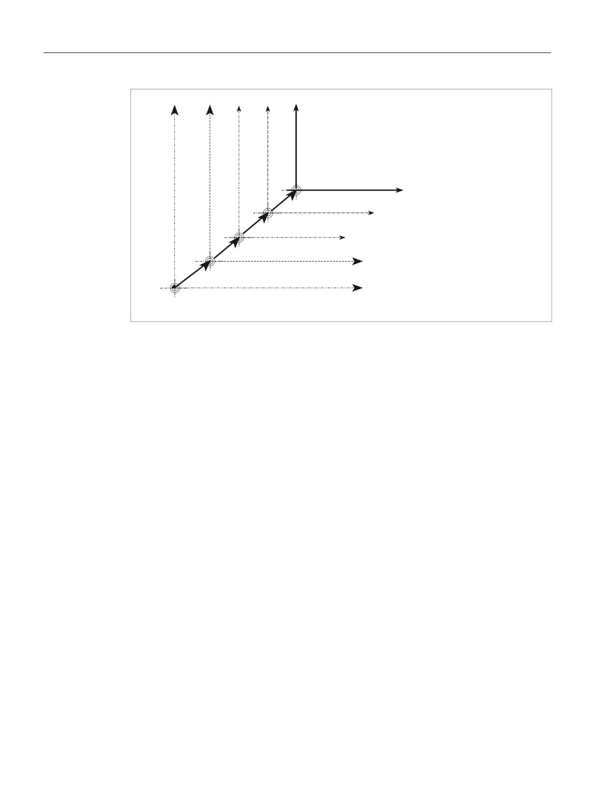
Coordinate transformations (frames)
6.8 NCU global frames
<
%&6
<
<
%=6
3B$&7%)5$0(
%=6
;
%=6
3B&+%)5$0(>Q@ Q
FDQ EH FRQILJXUHG YLD 0&B00B180B%$6(B)5$0(6
3B&+%)5$0(> @ 3B%)5$0(
3B1&%)5$0(>Q@ QFDQ EH FRQILJXUHG YLD 01B00B180B*/2%$/B%$6(B)5$0(6
;
3B1&%)5$0(> @
;
%&6
%=6 EDVLF ]HUR V\VWHP
%&6
%&6 EDVLF FRRUGLQDWH V\VWHP
3
$&7%)5$0( 3B1&%)5$0(> @ 3B1&%)5$0(>Q@ 3B&+%)5$0(> @ 3B&+%)5$0(>Q@
$P_CHBFRMASK and $P_NCBFRMASK Complete basic frame
The user can select which basic frames are to be included in the calculation of the "Complete"
basic frame via the system variables $P_CHBFRMASK and $P_NCBFRMASK. The variables
can only be programmed in the program and read via the OPI. The value of the variable is
interpreted as a bit mask and specifies which basic frame field element of $P_ACTFRAME is
to be included in the calculation.
$P_CHBFRMASK can be used to specify which channel-specific basic frames and
$P_NCBFRMASK can be used to specify which NCU global basic frames are to be included
in the calculation.
The complete basic frame and the complete frame are recalculated with the programming of
the variables. After a reset and in the basic setting, the values of $P_CHBFRMASK and
$P_NCBFRMASK are as follows:
$P_CHBFRMASK = $MC_CHBFRAME_RESET_MASK
$P_NCBFRMASK = $MC_CHBFRAME_RESET_MASK
Example:
$P_NCBFRMASK = 'H81' ;$P_NCBFRAME[0] : $P_NCBFRAME[7]
$P_CHBFRMASK = 'H11' ;$P_CHBFRAME[0] : $P_CHBFRAME[4]
$P_IFRAME Current settable frame
The predefined frame variable $P_IFRAME can be used to read and write the current settable
frame, which is valid in the channel, in the part program. The written settable frame is
immediately included in the calculation.
In the case of NCU global settable frames, the modified frame acts only in the channel in which
the frame was programmed. If the frame is to be modified for all channels of an NCU,
$P_UIFR[n] and $P_IFRAME must be written simultaneously. The other channels must then
activate the corresponding frame, e.g. with G54.
Job Planning
310
Programming Manual, 12/2018, A5E40869460B AB
Coordinate transformations (frames)
6.8 NCU global frames
$P_PFRAME Current programmable frame
$P_PFRAME is the programmable frame that results from the programming of TRANS/
ATRANS, G58/G59, ROT/AROT, SCALE/ASCALE, MIRROR/AMIRROR or from the
assignment of CTRANS, CROT, CMIRROR, CSCALE to the programmable frame.
Current, programmable frame variable that establishes the reference between the settable
zero system (SZS) and the workpiece coordinate system (WCS).
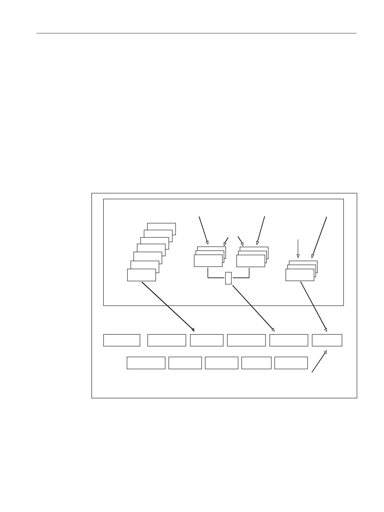
P_ACTFRAME Current complete frame
The resulting current complete frame $P_ACTFRAME is now a chain of all basic frames, the
current settable frame and the programmable frame. The current frame is always updated
whenever a frame component is changed.
$P_ACTFRAME corresponds to:
$P_PARTFRAME : $P_SETFRAME : $P_EXTFRAME : $P_ACTBFRAME : $P_IFRAME :
$P_TOOLFRAME : $P_WPFRAME : $P_TRAFRAME : $P_PFRAME : $P_CYCFRAME
'DWD PDQDJHPHQW IUDPHV
,QSXW YLD SURJUDP H J
,QSXW YLD SURJUDP H J
3B&+%)5 &75$16 =
3B1&%)5 &75$16 ;
3B8,)5>Q@ &75$16 ;
3B75$)5
,QSXW YLD
&KDQQHOVSHFLILF
,QSXW YLD
+0,
+0,
V\VWHP IUDPHV
3B&<&)5
3B:3)5
3B722/)5
3B3$57)5
3B&+%)5>Q@
3B1&%)5>Q@
3B(;7)5
&KDQQHO VSHFLILF 1&8
1&8 JOREDO
3B6(7)5
3B8,)5>Q@
EDVLF IUDPHV
IUDPHV
$FWLYDWHG YLD
$FWLYDWHG YLD
*
*
*
*
*
*
&RPSOHWH IUDPH
,QSXW YLD SURJUDP H J
$FWLYH FRPSOHWH IUDPH
3B1&%)5$0(> @ &75$16 ;
3B$&7)5$0(
3B3$57)5$0(
6(7)5$0(
3B(;7)5$0(
3B$&7%)5$0(
3B,)5$0(
3B722/)5$0(
3B:3)5$0(
3B75$)5$0(
3B3)5$0(
3B&<&)5$0(
,QSXW YLD SURJUDP H J
,QSXW YLD SURJUDP H J
3B3)5$0( &75$16 ;
3B,)5$0( &75$16 ;
RU
75$16 ;
Job Planning
Programming Manual, 12/2018, A5E40869460B AB
311
Coordinate transformations (frames)
6.8 NCU global frames
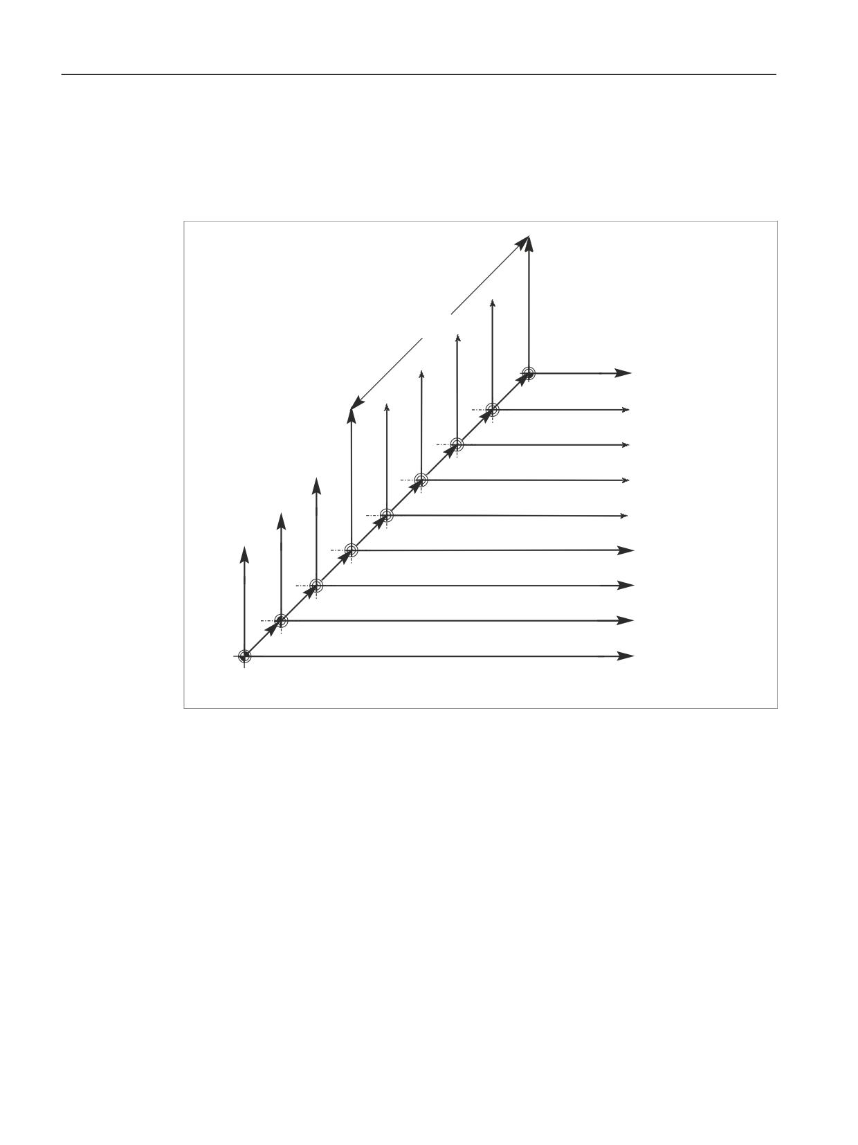
Frame chaining
The current frame is composed of the complete basic frame, the settable frame, the system
frame and the programmable frame in accordance with the current complete frame specified
above.
)UDPH FKDLQ
:&6
)UDPH IRU F\FOHV SURJUDPPDEOH IUDPH
WUDQVIRUPDWLRQV
6=6
6\VWHP IUDPH IRU 72527 72)5$0(
ZRUNSLHFHV
*
*
VHW IUDPH FKDQQHO VSHF RU
1&8 JOREDO
%=6
&KDLQHG DUUD\ RI EDVLF IUDPHV FKDQQHO VSHF
DQG RU 1&8 JOREDO
&KDLQHG V\VWHP IUDPHV IRU 3$527 VHW DFWXDO YDOXH VFUDWFKLQJ
]HUR RIIVHW H[WHUQDO
+DQGZKHHO '5) RIIVHW VXSHULPSRVHG PRYHPHQW >]HUR RIIVHW
H[WHUQDO@
%&6
.LQHPDWLF WUDQVIRUPDWLRQ
0&6
+RPH SRVLWLRQ RIIVHW
0&6 0DFKLQH &RRUGLQDWH 6\VWHP
%&6 %DVLF &RRUGLQDWH 6\VWHP
:&6 :RUNSLHFH &RRUGLQDWH 6\VWHP
%=6 %DVLF =HUR 6\VWHP
6=6 6HWWDEOH =HUR 6\VWHP
Job Planning
312
Programming Manual, 12/2018, A5E40869460B AB
Transformations
7
7.1
General programming of transformation types
General function
You can choose to program transformation types with suitable parameters in order to adapt
the controller to various machine kinematics. These parameters can be used to declare both
the orientation of the tool in space and the orientation movements of the rotary axes accordingly
for the selected transformation.
In three-, four-, and five-axis transformations, the programmed positional data always relates
to the tip of the tool, which is tracked orthogonally to the machined surface in space. The
Cartesian coordinates are converted from the basic coordinate system to the machine
coordinate system and relate to the geometry axes. These describe the operating point. Virtual
rotary axes describe the orientations of the tool in space and are programmed with TRAORI.
In the case of kinematic transformation, positions can be programmed in the Cartesian
coordinate system. The controller maps the Cartesian coordinate system traversing
movements programmed with TRANSMIT, TRACYL and TRAANG to the traversing
movements of the real machine axes.
Programming
Three, four and five axis transformations (TRAORI)
The orientation transformation declared is activated with the TRAORI command and the three
possible parameters for transformation number, orientation vector and rotary axis offsets.
TRAORI(transformation number, orientation vector, rotary axis
offsets)
Kinematic transformations
TRANSMIT(transformation number) declared transformations are examples of
kinematic transformation.
TRACYL(working diameter, transformation number)
TRAANG(angle of offset axis, transformation number)
Deactivate active transformation
TRAFOOF can be used to deactivate the currently active transformation.
Orientation transformation
Three, four and five axis transformations (TRAORI)
For the optimum machining of surfaces configured in space in the working area of the machine,
machine tools require other axes in addition to the three linear axes X, Y and Z. The additional
Job Planning
Programming Manual, 12/2018, A5E40869460B AB
313
Transformations
7.1 General programming of transformation types
axes describe the orientation in space and are called orientation axes in subsequent sections.
They are available as rotary axes on four types of machine with varying kinematics.
1. Two-axis swivel head, e.g. cardanic tool head with one rotary axis parallel to a linear axis
on a fixed tool table.
2. Two-axis rotary table, e.g. fixed swivel head with tool table, which can rotate about two
axes.
3. Single-axis swivel head and single-axis rotary table, e.g. one rotatable swivel head with
rotated tool for tool table, which can rotate about one axis.
4. Two-axis swivel head and single-axis rotary table, e.g. on tool table, which can rotate about
one axis, and one rotatable swivel head with tool, which can rotate about itself.
3- and 4-axis transformations are special types of 5-axis transformation and are programmed
in the same way as 5-axis transformations.
The functional scope of "generic 3-/4-/5-/6-axis transformation" is suitable both for
transformations for orthogonal rotary axes and transformations for the universal milling head
and, like all other orientation transformations, can also be activated for these four machine
types with TRAORI. In generic 5-/6-axis transformation, tool orientation has an additional third
degree of freedom, whereby the tool can be rotated about its own axis relative to the tool
direction so that it can be directed as required in space.
References: /FB3/ Function Manual, Special Functions; 3- to 5-Axis Transformation (F2)
Initial tool orientation setting regardless of kinematics
ORIRESET
If an orientation transformation is active using TRAORI, then ORIRESET can be used to specify
the initial settings of up to 3 orientation axes with the optional parameters A, B, C. The order
in which the programmed parameters are assigned to the round axes depends on the
orientation axis order defined by the transformation. Programming ORIRESET(A, B, C) results
in the orientation axes moving in linear and synchronous motion from their current position to
the specified initial setting position.
Kinematic transformations
TRANSMIT and TRACYL
For milling on turning machines, either
1. Face machining in the turning clamp with TRANSMIT or
2. Machining of grooves with any path on cylindrical bodies with TRACYL
can be programmed for the transformation declared.
TRAANG
If the option of setting the infeed axis for inclined infeed is required (for grinding technology,
for example), TRAANG can be used to program a configurable angle for the transformation
declared.
Cartesian PTP travel
Job Planning
314
Programming Manual, 12/2018, A5E40869460B AB
Transformations
7.1 General programming of transformation types
Kinematic transformation also includes the so-called "Cartesian PTP travel" for which up to 8
different articulated joint positions STAT= can be programmed. Although the positions are
programmed in a Cartesian coordinate system, the movement of the machine occurs in the
machine coordinates.
References:
/FB2/ Function Manual, Extended Functions; Kinematic Transformation (M1)
Chained transformations
Two transformations can be switched one after the other. For the second transformation
chained here, the motion parts for the axes are taken from the first transformation.
The first transformation can be:
● Orientation transformation TRAORI
● Polar transformation TRANSMIT
● Cylinder transformation TRACYL
● Inclined axis transformation TRAANG
The second transformation must be a TRAANG type transformation for an inclined axis.
7.1.1
Orientation movements for transformations
Travel movements and orientation movements
The traversing movements of the programmed orientations are determined primarily by the
type of machine. For three-, four-, and five-axis type transformations with TRAORI, the rotary
axes or pivoting linear axes describe the orientation movements of the tool.
Changes in the position of the rotary axes involved in the orientation transformation will induce
compensating movements on the remaining machine axes. The position of the tool tip remains
unchanged.
Orientation movements of the tool can be programmed using the rotary axis identifiers A…,
B…, C… of the virtual axes as appropriate for the application either by entering Euler or RPY
angles or directional or surface normal vectors, normalized vectors for the rotary axis of a taper
or for intermediate orientation on the peripheral surface of a taper.
In the case of kinematic transformation with TRANSMIT, TRACYL and TRAANG, the controller
maps the programmed Cartesian coordinate system traversing movements to the traversing
movements of the real machine axes.
Job Planning
Programming Manual, 12/2018, A5E40869460B AB
315
Transformations
7.1 General programming of transformation types
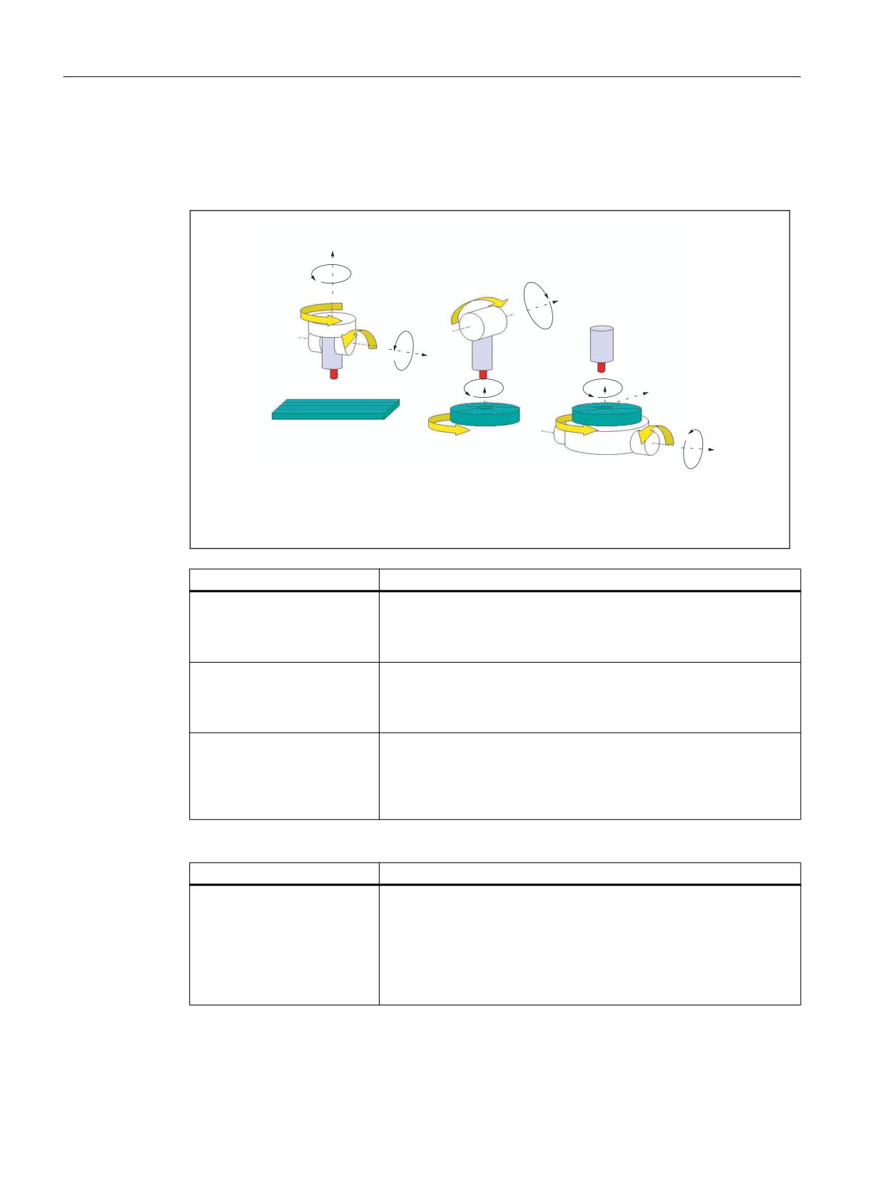
Machine kinematics for three, four and five axis transformation (TRAORI)
Either the tool or the tool table can be rotatable with up to two rotary axes. A combination of
swivel head and rotary table (single-axis in each case) is also possible.
6ZLYHO KHDG
6ZLYHO KHDG
6ZLYHO KHDG
=
FDQ EH URWDWHG
FDQ EH URWDWHG
IL[HG
DERXW ; D[LV
DERXW < D[LV
DQG = D[LV
&
%
<
7RRO WDEOH FDQ
7RRO WDEOH FDQ
EH URWDWHG
$
EH URWDWHG
DERXW ; D[LV
;
DERXW = D[LV
DQG = D[LV
=
=
&
&
<
7RRO WDEOH IL[HG
$
;
5RWDWHG WRRO
5RWDWHG WRRO 5RWDWHG
5RWDWHG ZRUNSLHFH
ZRUNSLHFH
0DFKLQH W\SH ZLWK
0DFKLQH W\SH ZLWK
0DFKLQH W\SH ZLWK
D[LV VHTXHQFH &$
D[LV VHTXHQFH %&
D[LV VHTXHQFH $&
Machine type
Programming of orientation
Three-axis transformation ma-
Programming of tool orientation only in the plane, which is perpendic-
chine types 1 and 2
ular to the rotary axis. There are
two translatory axes (linear axes) and
one axis of rotation (rotary axis).
Four-axis transformation ma-
Programming of tool orientation only in the plane, which is perpendic-
chine types 1 and 2
ular to the rotary axis. There are
three translatory axes (linear axes) and
one axis of rotation (rotary axis).
Five-axis transformation ma-
Programming of orientation transformation. Kinematics with
chine types 3
three linear axes and two orthogonal rotary axes.
Single-axis swivel head and
The rotary axes are parallel to two of the three linear axes. The first
single-axis rotary table
rotary axis is moved by two Cartesian linear axes. It rotates the third
linear axis with the tool. The second rotary axis rotates the workpiece.
Generic 5/6-axis transformations
Machine type
Programming of orientation transformation
Generic five/six-axis transfor-
Programming of orientation transformation. Kinematics with
mation machine types 4
three linear axes and three orthogonal rotary axes.
Two-axis swivel head with tool
The rotary axes are parallel to two of the three linear axes. The first
which rotates around itself and
rotary axis is moved by two Cartesian linear axes. It rotates the third
single-axis rotary table
linear axis with the tool. The second rotary axis rotates the workpiece.
The basic tool orientation can also be programmed with additional ro-
tation of the tool around itself with the THETA rotary angle.
When calling "generic three-, four-, and five/six-axis transformation", the basic orientation of
the tool can also be transferred. The restrictions in respect of the directions of the rotary axes
no longer apply. If the rotary axes are not exactly vertical to one another or existing rotary axes
Job Planning
316
Programming Manual, 12/2018, A5E40869460B AB

Transformations
7.1 General programming of transformation types
are not exactly parallel with the linear axes, "generic five-/six-axis transformation" can provide
better results in respect of tool orientation.
Kinematic transformations TRANSMIT, TRACYL and TRAANG
For milling on turning machines or an axis that can be set for inclined infeed during grinding,
the following axis arrangements apply by default in accordance with the transformation
declared:
TRANSMIT
Activation of polar transformation
Face machining in the turning
A rotary axis
clamp
An infeed axis vertical to the axis of rotation
A longitudinal axis parallel to the axis of rotation
TRACYL
Activation of the cylinder surface transformation
Machining of grooves with any
A rotary axis
path on cylindrical bodies
An infeed axis vertical to the axis of rotation
A longitudinal axis parallel to the axis of rotation
TRAANG
Activation of the inclined axis transformation
Machining with an oblique in-
A rotary axis
feed axis
An infeed axis with parameterizable angle
A longitudinal axis parallel to the axis of rotation
Cartesian PTP travel
The machine moves in machine coordinates and is programmed with:
TRAORI
Activation of transformation
PTP point-to-point traversing
Approach position in Cartesian coordinate system (MCS)
CP
Path motion of Cartesian axes in the BCS
STAT
Position of the articulated joints is dependent on the transformation
TU
The angle at which the axes traverse on the shortest path
PTP transversal with generic 5/6-axis transformation
The machine is moved using machine coordinates and the tool orientation, where the
movements can be programmed both using round axis positions and using Euler and/or RPY
angle vectors irrespective of the kinematics or the direction vectors.
Round axis interpolation, vector interpolation with large circle interpolation or interpolation of
the orientation vector on a peripheral surface of a taper are possible in such cases.
Job Planning
Programming Manual, 12/2018, A5E40869460B AB
317
Transformations
7.1 General programming of transformation types
Example: Three- to five-axis transformation on a universal milling head
The machine tool has at least five axes:
● Three translatory axes for movements in straight lines, which move the operating point to
any position in the working area.
● Two rotary swivel axes arranged at a configurable angle (usually 45 degrees) allow the tool
to swivel to positions in space that are limited to a half sphere in a 45-degree configuration.
Job Planning
318
Programming Manual, 12/2018, A5E40869460B AB
Transformations
7.1 General programming of transformation types
7.1.2
Overview of orientation transformation TRAORI
Programming types available in conjunction with TRAORI
Machine type
Programming with active transformation TRAORI
Machine types 1, 2, or 3 two-
The axis sequence of the orientation axes and the orientation direction
axis swivel head or two-axis
of the tool can either be configured on a
rotary table or a combination
machine-specific basis using machine data
of single-axis swivel head and
depending on the machine kinematics or on a
single-axis rotary table.
workpiece-specific basis with programmable orientation
independently of the machine kinematics.
The directions of rotation of the orientation axes in the reference sys-
tem are programmed with:
- ORIMKS reference system = machine coordinate system
- ORIWKS reference system = workpiece coordinate system
The default setting is ORIWKS.
Programming of orientation axes with:
A, B, C of the machine axis position direct
A2, B2, C2 angle programming virtual axes with
- ORIEULER via Euler angle (standard)
- ORIRPY via RPY angle
- ORIVIRT1 via virtual orientation axes 1st definition
- ORIVIRT2 via virtual orientation axes 2nd definition
with differentiation between the interpolation type:
linear interpolation
- ORIAXES of orientation axes or machine axes
large radius circle interpolation (interpolation of the orientation vector)
- ORIVECT from orientation axes
Programming orientation axes by specifying
A3, B3, C3 of the vector components (direction/surface normal)
Programming the resulting tool orientation
A4, B4, C4 of the vector surface normal at the beginning of the block
A5, B5, C5 of the vector perpendicular to the surface at the end of the
block
LEAD leading angle for tool orientation
TILT tilt angle for the tool orientation
Job Planning
Programming Manual, 12/2018, A5E40869460B AB
319

Transformations
7.1 General programming of transformation types
Machine type
Programming with active transformation TRAORI
Interpolation of the orientation vector on a taper peripheral surface
Orientation changes to a taper peripheral surface anywhere in space
using
interpolation:
- ORIPLANE in the plane (large radius circle interpolation)
- ORICONCW on a taper peripheral surface in the clockwise direction
- ORICONCCW on a taper peripheral surface in the counter-clockwise
direction
A6, B6, C6 director vector (axis of rotation of the taper)
-OICONIO interpolation on a taper peripheral surface with:
A7, B7, C7 intermediate vectors (initial and ultimate orientation) or
- ORICONTO on the peripheral surface of a taper, tangential transition
Changes in orientation in relation to a path with
- ORICURVE specification of the movement of two contact points using
PO[XH]=(xe, x2, x3, x4, x5) orientation polynomials up to the fifth de-
gree
PO[YH]=(ye, y2, y3, y4, y5) orientation polynomials up to the fifth de-
gree
PO[ZH]=(ze, z2, z3, z4, z5) orientation polynomials up to the fifth de-
gree
- ORIPATHS smoothing of orientation characteristic with
A8, B8, C8 reorientation phase of tool corresponding to: direction and
path length of tool during retraction movement
Machine types 1 and 3
Programming of rotations for tool orientation with
LEAD angle, angle relative to surface normal vector
PO[PHI] programming of a polynomial up to the fifth degree
TILT angle rotation about path tangent (Z direction)
PO[PSI] programming of a polynomial up to the fifth degree
Other machine types with ad-
THETA angle of rotation (rotation about tool direction in Z)
ditional tool rotation around it-
THETA= value reached at end of block
self require a 3rd rotary axis
THETA=AC(...) absolute non-modal switching to dimensions
THETA=IC(...) non-modal switching to chain dimensions
THETA=Θe interpolate programmed angle G90/G91
Orientation transformation,
PO[THT]=(..) programming of a polynomial up to the fifth degree
e.g. generic 6-axis transforma-
programming of the rotation vector
tion. Rotations of orientation
- ORIROTA rotation, absolute
vector.
- ORIROTR relative rotation vector
- ORIROTT tangential rotation vector
Orientation relative to the path
Changes in orientation relative to the path with
for orientation changes rela-
- ORIPATH tool orientation relative to the path
tive to the path or rotation of
- ORIPATHS also in the event of a blip in the orientation characteristic
the rotary vector tangentially
programming of rotation vector
to the path
- ORIROTC tangential rotation vector, rotation to path tangent
Job Planning
320
Programming Manual, 12/2018, A5E40869460B AB
Transformations
7.2 Three, four and five axis transformation (TRAORI)
7.2
Three, four and five axis transformation (TRAORI)
7.2.1
General relationships of universal tool head
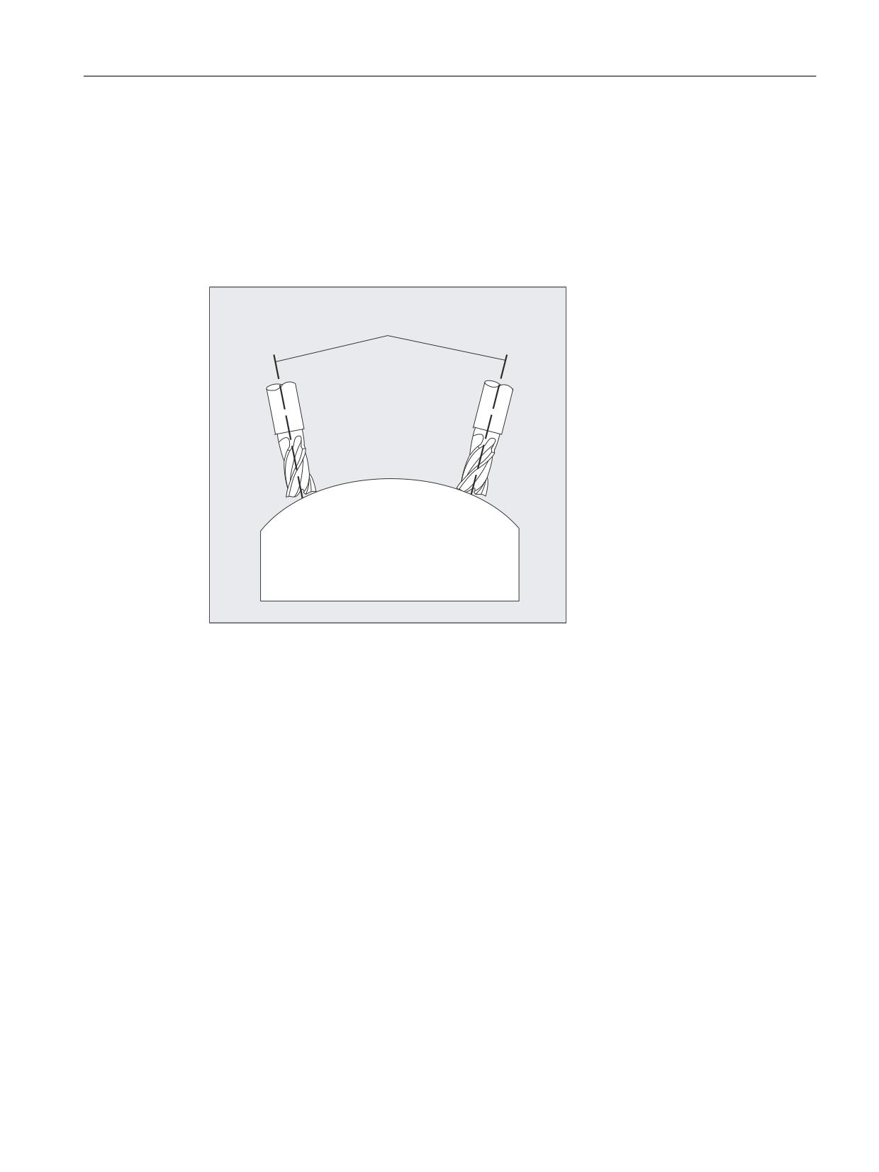
To obtain optimum cutting conditions when machining surfaces with a three-dimensional curve,
it must be possible to vary the setting angle of the tool.
7RRO D[LV
The machine design to achieve this is stored in the axis data.
5-axis transformation
Cardanic tool head
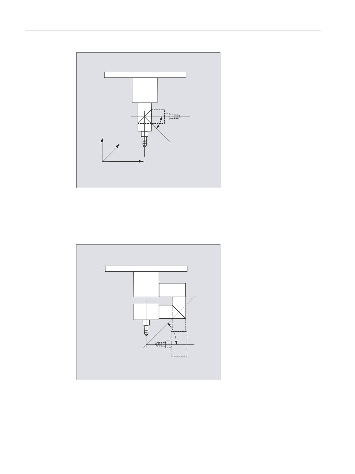
Three linear axes (X, Y, Z) and two orientation axes (C, A) define the setting angle and the
operating point of the tool here. One of the two orientation axes is created as an inclined axis,
in our example A' - in many cases, placed at 45°.
Job Planning
Programming Manual, 12/2018, A5E40869460B AB
321
Transformations
7.2 Three, four and five axis transformation (TRAORI)
́
$
=
<
&
;
&DUGDQLF WRRO KHDG YDULDQW
In the examples shown here, you can see the arrangements as illustrated by the CA machine
kinematics with the Cardanic tool head!
Machine manufacturer
The axis sequence of the orientation axes and the orientation direction of the tool can be set
up using the machine data as appropriate for the machine kinematics.
$
&
́
&DUGDQLF WRRO KHDG YDULDQW
In this example, A' lies below the angle φ to the X axis.
Job Planning
322
Programming Manual, 12/2018, A5E40869460B AB
Transformations
7.2 Three, four and five axis transformation (TRAORI)
The following possible relations are generally valid:
A' lies below the angle φ to the
X axis
B' lies below the angle φ to the
Y axis
C' lies below the angle φ to the
Z axis
Angle φ can be configured in the range 0° to +89° using machine data.
With swiveling linear axis
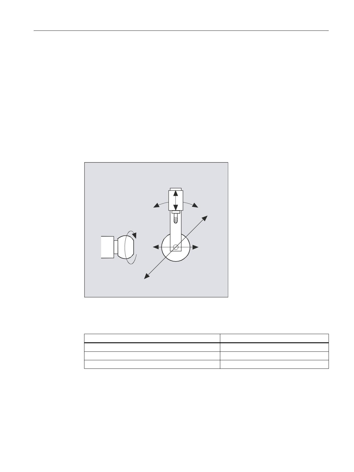
This is an arrangement with a moving workpiece and a moving tool. The kinematics consists
of three linear axes (X, Y, Z) and two orthogonally arranged rotary axes. The first rotary axis
is moved, for example, over a compound slide of two linear axes, the tool standing parallel to
the third linear axis. The second rotary axis turns the workpiece. The third linear axis (swivel
axis) lies in the compound slide plane.
=
$
<
%
;
The axis sequence of the rotary axes and the orientation direction of the tool can be set up
using the machine data as appropriate for the machine kinematics.
There are the following possible relationships:
Axes:
Axis sequences:
1. rotary axis
A A B B C C
2. rotary axis
B C A C A B
Swiveled linear axis
Z Y Z X Y X
For more detailed information about configurable axis sequences for the orientation direction
of the tool, see
References: /FB3/ Function Manual, Special Functions; 3- to 5-Axis Transformations (F2),
Section Universal milling head, "Parameterization".
Job Planning
Programming Manual, 12/2018, A5E40869460B AB
323

Transformations
7.2 Three, four and five axis transformation (TRAORI)
7.2.2
Three, four and five axis transformation (TRAORI)
The user can configure two or three translatory axes and one rotary axis. The transformations
assume that the rotary axis is orthogonal on the orientation plane.
Orientation of the tool is possible only in the plane perpendicular to the rotary axis. The
transformation supports machine types with movable tool and movable workpiece.
Three- and four-axis transformations are configured and programmed in the same way as five-
axis transformations.
Reference:
Function Manual, Special Functions; Multi-Axis Transformations (F2)
Syntax
TRAORI(<n>)
TRAORI(<n>,<X>,<Y>,<Z>,<A>,<B>)
TRAFOOF
Meaning
TRAORI:
Activates the first specified orientation transformation
TRAORI(<n>):
Activates the orientation transformation specified by n
<n>:
Number of the transformation
Value:
1 or 2
Example:
TRAORI(1) activates orientation transformation 1
<X>,<Y>,<Z>:
Component of orientation vector to which tool points
<A>,<B>:
Programmable offset for the rotary axes
TRAFOOF:
Deactivate transformation
Tool orientation
Depending on the orientation direction selected for the tool, the active working plane (G17,
G18, G19) must be set in the NC program in such a way that tool length offset works in the
direction of tool orientation.
Note
When the transformation is enabled, the positional data (X, Y, Z) always relates to the tip of
the tool. Changing the positions of the rotary axes involved in the transformation causes
compensating motion of the remaining machine axes - which means that the position of the
tool tip remains unchanged.
Orientation transformation always points from the tool tip to the tool adapter.
Offset for orientation axes
When orientation transformation is activated an additional offset can be programmed directly
for the orientation axes.
Job Planning
324
Programming Manual, 12/2018, A5E40869460B AB
Transformations
7.2 Three, four and five axis transformation (TRAORI)
Parameters can be omitted if the correct sequence is used in programming.
Example:
TRAORI(, , , ,A,B) ; If only a single offset is to be entered
As an alternative to direct programming, the additional offset for orientation axes can also be
transferred automatically from the zero offset currently active. Transfer is configured in the
machine data.
Examples
TRAORI(1,0,0,1)
; The basic orientation of the tool is in the Z direction
TRAORI(1,0,1,0)
; The basic orientation of the tool is in the Z direction
TRAORI(1,0,1,1)
; The basic orientation of the tool is in the Y/Z direction
(corresponds to the position -45°)
7.2.3
Variants of orientation programming and initial setting (ORIRESET)
Orientation programming of tool orientation with TRAORI
In conjunction with a programmable TRAORI orientation transformation, in addition to the linear
axes X, Y, Z, the rotary axis identifiers A.., B..., C... can also be used to program axis positions
or virtual axes with angles or vector components. Various types of interpolation are possible
for orientation and machine axes. Regardless of which PO[angle] orientation polynomials and
PO[axis] axis polynomials are currently active, a number of different types of polynomial can
be programmed. These include G1, G2, G3, CIP or POLY.
Changes in tool orientation can even be programmed using orientation vectors in some cases.
In such cases, the ultimate orientation of each block can be set either by means of direct
programming of the vector or by programming the rotary axis positions.
Variants of orientation programming for three- to five-axis transformation
The following versions of orientation programming are mutually exclusive.
A, B, C
Direct entry of rotary axis positions.
A2, B2, C2
Angle programming of virtual axes via Euler angles or RPY angles
A3, B3, C3
Vector component designation
LEAD, TILT
Specification of lead and tilt angles with reference to path and surface
A4, B4, C4
Surface normal vectors at the start of the block and at the end of the
A5, B5, C5
block
A6, B6, C6
Interpolation of the orientation vector on a taper surface transformation.
A7, B7, C7
A8, B8, C8
Redirection of the tool, direction and path length of the retraction move-
ment
Job Planning
Programming Manual, 12/2018, A5E40869460B AB
325
Transformations
7.2 Three, four and five axis transformation (TRAORI)
Approach initial setting of the tool orientation (ORIRESET)
Through ORIRESET(...), the orientation axes of the relevant machine kinematics are
traversed linearly and synchronously from their current positions to the programmed initial
state positions. If a basic position is not programmed for an axis, the position from the
associated machine data $MC_TRAFO5_ROT_AX_OFFSET_1/2 is used.
Active frames of rotary axes are ignored.
Examples of machine kinematics CA (channel axis names C, A)
Commands
Description
ORIRESET(90, 45)
Axis C: 90°
Axis A: 45°
ORIRESET(, 30)
Axis C: $MC_TRAFO5_ROT_AX_OFFSET_1/2[0]
Axis A: 30°
ORIRESET( )
Axis C: $MC_TRAFO5_ROT_AX_OFFSET_1/2[0]
Axis A: $MC_TRAFO5_ROT_AX_OFFSET_1/2[1]
Examples of machine kinematics CAC (channel axis names C, A, B)
Commands
Description
ORIRESET(90, 45, 90)
Axis C: 90°
Axis A: 45°
Axis B: 90°
ORIRESET( )
Axis C: $MC_TRAFO5_ROT_AX_OFFSET_1/2[0]
Axis A: $MC_TRAFO5_ROT_AX_OFFSET_1/2[1]
Axis B: $MC_TRAFO5_ROT_AX_OFFSET_1/2[2]
Note
Travel to the initial state of the tool orientation with ORIRESET...) may only take place with
active orientation transformation TRAORI...).
Programming LEAD, TILT and THETA rotations
Lead angle LEAD and tilt angle TILT.
In respect of three- to five-axis transformation, tool orientation rotations are programmed with
the LEAD and TILT angles.
Angle of rotation THETA
For a transformation with third rotary axis, the rotation of the tool about itself can be
programmed with the THETA rotary angle both for orientation with vector components as well
as for programming the angles LEAD, TILT.
Job Planning
326
Programming Manual, 12/2018, A5E40869460B AB
Transformations
7.2 Three, four and five axis transformation (TRAORI)
7.2.4
Programming the tool orientation (A..., B..., C..., LEAD, TILT)
The following options are available when programming tool orientation:
1. Direct programming the motion of rotary axes. The change of orientation always occurs in
the basic or machine coordinate system. The orientation axes are traversed as
synchronized axes.
2. Programming in Euler or RPY angles in accordance with angle definition using A2, B2,
C2
3. Programming the direction vector using A3, B3, C3 The direction vector points from the
tool tip toward the tool adapter.
4. Programming the surface normal vector at the start of the block with A4, B4, C4 and at
the end of the block with A5, B5, C5 (face milling).
5. Programming using lead angle LEAD and tilt angle TILT
6. Programming the rotary axis of taper as normalized vector using A6, B6, C6 or of
intermediate orientation on the peripheral surface of a taper using A7, B7, C7,
see "Orientation programming along the peripheral surface of a taper (ORIPLANE,
ORICONxx)".
7. Programming the reorientation, direction and path length of tool during retraction movement
using A8, B8, C8,
see "Smoothing the orientation characteristic (ORIPATHS A8=, B8=, C8=)"
Note
In all cases, orientation programming is only permissible if an orientation transformation is
active.
Advantage: These programs can be transferred to any machine kinematics.
Job Planning
Programming Manual, 12/2018, A5E40869460B AB
327
Transformations
7.2 Three, four and five axis transformation (TRAORI)
Definition of tool orientation via G command
Note
Machine manufacturer
Machine data can be used to switch between Euler or RPY angles. If the machine data is set
accordingly, changeovers are possible both depending on the active G command of group 50
and irrespective of this. The following setting options can be selected:
1. If both machine data for defining the orientation axes and defining the orientation angle are
set to zero via G command:
The angles programmed using A2, B2, C2 are dependent on machine data The angle
definition of orientation programming is either interpreted as Euler or RPY angles.
2. If the machine data for defining the orientation axes is set to one via G command, the
changeover is
dependent on the active G command of group 50:
The angles programmed using A2, B2, C2 are interpreted in accordance with the active
G commands ORIEULER, ORIRPY, ORIVIRT1, ORIVIRT2, ORIAXPOS and
ORIPY2 . The values programmed with the orientation axes are also interpreted as
orientation angles in accordance with the active G command of group 50.
3. If the machine data for defining the orientation angle is set to one via G command and the
machine data for defining the orientation axes is set to zero via G command, the changeover
is
not dependent on the active G command of group 50:
The angles programmed using A2, B2, C2 are interpreted in accordance with one of the
active G commands ORIEULER, ORIRPY, ORIVIRT1, ORIVIRT2 ORIAXPOS and
ORIPY2. The values programmed with the orientation axes are always interpreted as round
axis positions irrespective of the active G command of group 50.
Syntax
Rotary axis positions
G1 X<Value> Y<Value> Z<Value> A<Value> B<Value> C<Value>
Euler angles
G1 X<Value> Y<Value> Z<Value> A2<Value> B2<Value> C2<Value>
Direction vector
G1 X<Value> Y<Value> Z<Value> A3<Value> B3<Value> C3<Value>
Surface normal vector at block start
G1 X<Value> Y<Value> Z<Value> A4<Value> B4<Value> C4<Value>
Surface normal vector at the end of the block
G1 X<Value> Y<Value> Z<Value> A5<Value> B5<Value> C5<Value>
Lead angle
LEAD=<Value>
Job Planning
328
Programming Manual, 12/2018, A5E40869460B AB

Transformations
7.2 Three, four and five axis transformation (TRAORI)
Tilt angle
TILT=<Value>
Meaning
G1:
Linear interpolation
X, Y, Z:
Linear axis positions
A, B, C:
Rotary axis positions
A2=, B2=, C2=:
Angle programming (Euler or RPY angle)
A3=, B3=, C3=:
Directional vectors in the X, Y and Z coordinates of the WCS.
A4=, B4=, C4=:
Surface normal vectors at the start of the block in the X, Y and Z coordinates
of the WCS.
A5=, B5=, C5=:
Surface normal vectors at the end of the block in the X, Y and Z coordinates
of the WCS.
LEAD= :
Leading angle 1)
TILT= :
Tilt angle 1)
1) The interpretation of the angle indications depend on the setting in MD21094 $MC_ORIPATH_MODE
Further information
5-axis programs are usually generated by CAD/CAM systems and not entered at the control.
So the following explanations are directed mainly at programmers of postprocessors.
The following commands are available for orientation programming:
Command
Meaning
ORIEULER:
Euler angle with rotation sequence ZX'Z''
ORIRPY:
RPY angle with rotation sequence XY'Z''
ORIRPY2:
RPY angle with rotation sequence ZY'X''
ORIVIRT1:
Virtual orientation axes with freely definable rotation sequence via:
MD21120 $MC_ORIAX_TURN_TAB_1
ORIVIRT2:
Virtual orientation axes with freely definable rotation sequence via:
MD21130 $MC_ORIAX_TURN_TAB_2
ORIAXPOS:
Virtual orientation axes with rotary axis positions
Note
The machine manufacturer can use machine data to define various variants. Please refer to
the machine manufacturer's instructions.
Programming in Euler angles ORIEULER, rotation sequence Z X' Z''
The values programmed during ORIEULER orientation programming with A2, B2, C2 are
interpreted as Euler angles (in degrees).
Job Planning
Programming Manual, 12/2018, A5E40869460B AB
329
Transformations
7.2 Three, four and five axis transformation (TRAORI)
The new orientation vector results from the following three rotations of the original orientation
vector
1. with the rotary axis A2 about the coordinate axis Z
2. with the rotary axis B2 about the new coordinate axis X'
3. with the rotary axis C2 about the coordinate axis Z"
In this case the value of C2 (rotation around the new Z axis) is meaningless and does not have
to be programmed.
Programming in RPY angles ORIRPY, rotation sequence X Y' Z''
The values programmed during ORIEULER orientation programming with A2, B2, C2 are
interpreted as RPY angles (in degrees) with the rotation sequence X Y' Z''.
Note
In contrast to programming with ORIEULER, with ORIRPY all three values here have an effect
on the orientation vector.
The new orientation vector results from the following three rotations of the original orientation
vector
1. with the rotary axis A2 about the coordinate axis X
2. with the rotary axis B2 about the new coordinate axis Y'
3. with the rotary axis C2 about the coordinate axis Z"
Programming the directional vector
The components of the direction vector are programmed with A3, B3, C3. The vector points
towards the tool adapter; the length of the vector is of no significance.
Vector components that have not been programmed are set equal to zero.
Job Planning
330
Programming Manual, 12/2018, A5E40869460B AB
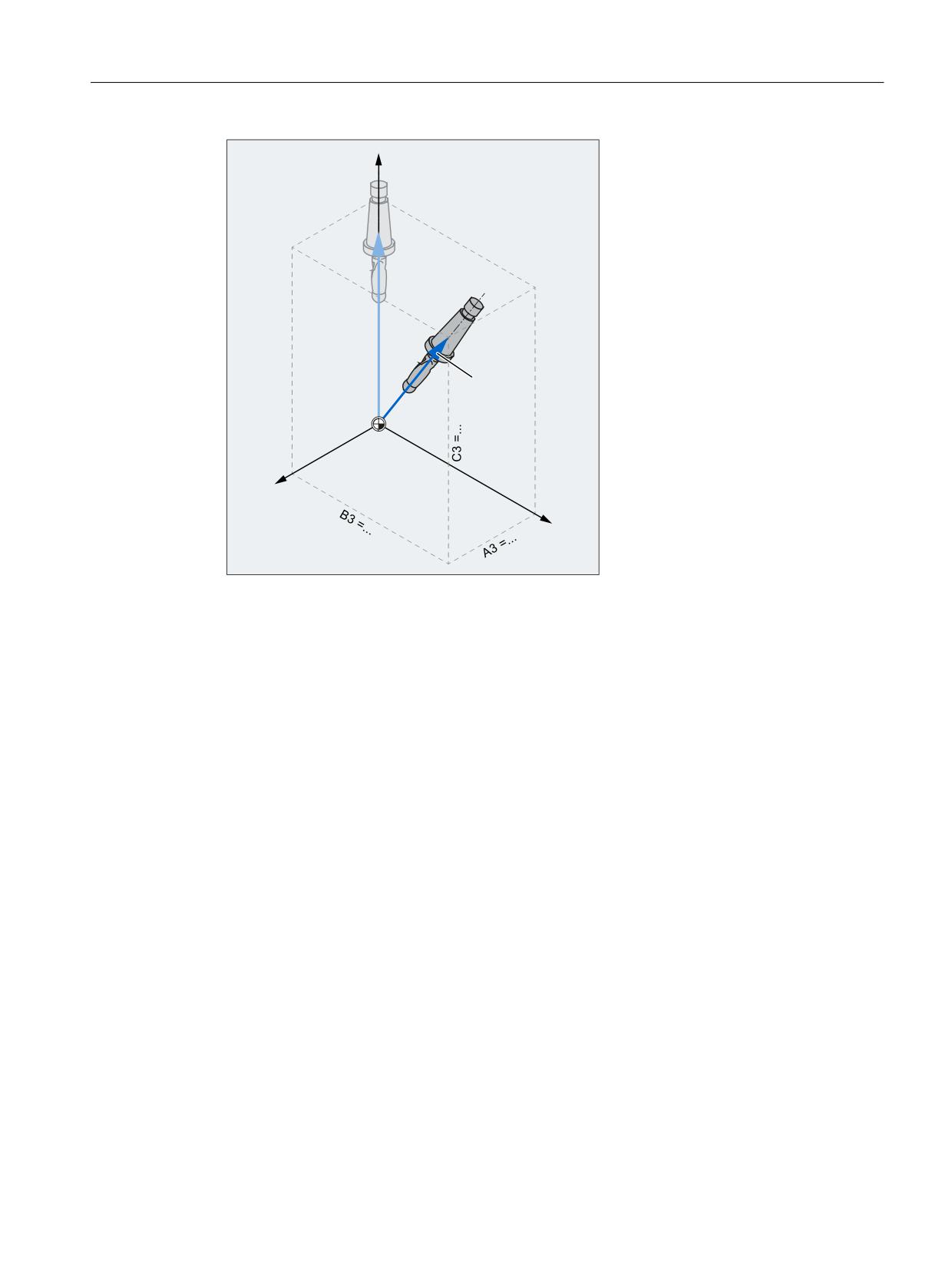
Transformations
7.2 Three, four and five axis transformation (TRAORI)
=
2
;
<
X, Y, Z
Coordinate axes of the WCS
A3, B3,
Components of the directional vector
C3
O
Orientation vector
Figure 7-1
Programming the directional vector
Programming the tool orientation with LEAD and TILT
The resultant tool orientation is determined from:
● Path tangent
● Surface normal vector
At the start of the block A4, B4, C4 and at the end of the block A5, B5, C5
● Lead angle LEAD
Angle in the plane defined by the path tangent and surface normal vector
● Tilt angle TILT at end of block
Angle in the plane, perpendicular to the path tangent relative to the surface normal vector
Job Planning
Programming Manual, 12/2018, A5E40869460B AB
331
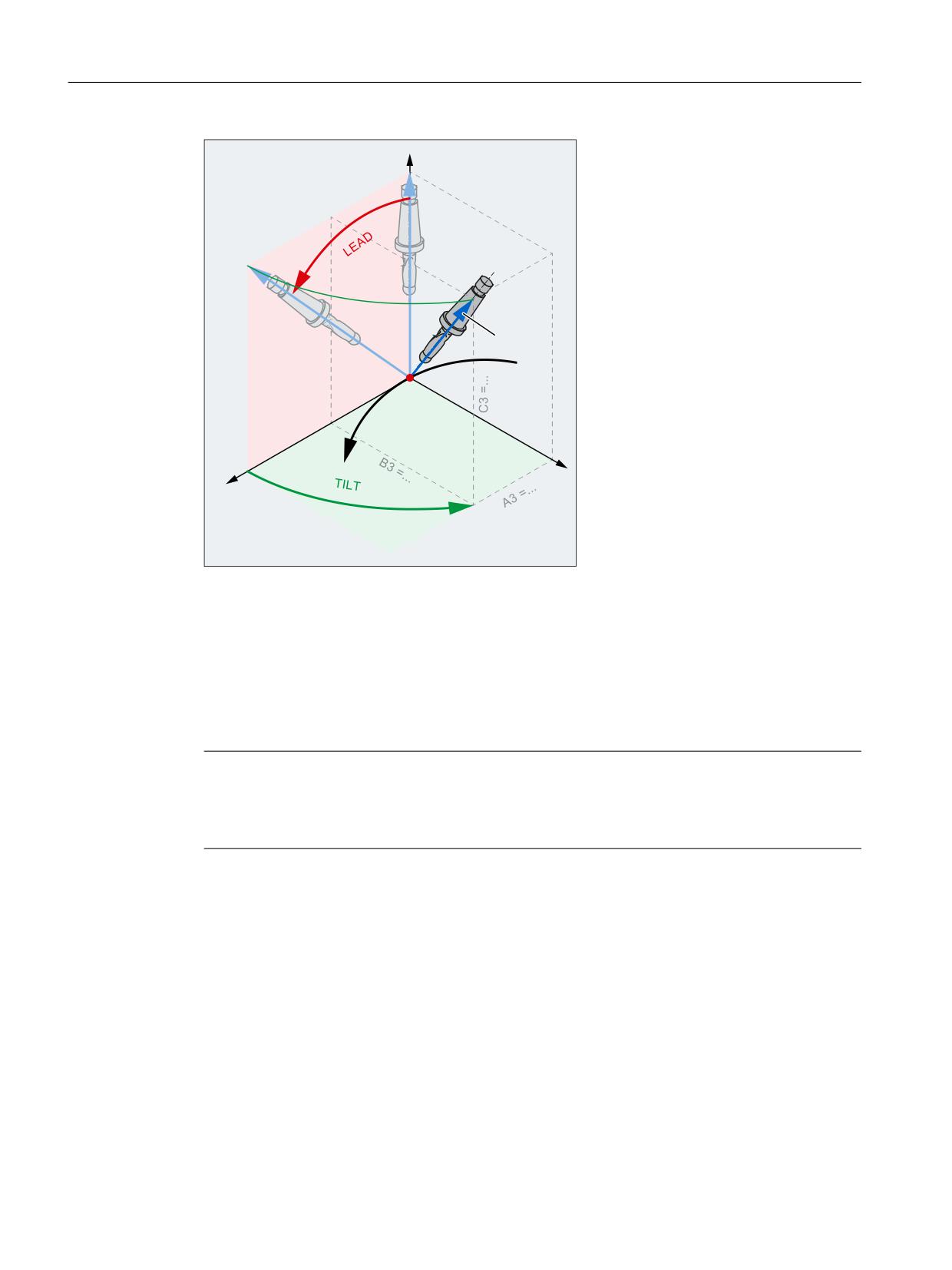
Transformations
7.2 Three, four and five axis transformation (TRAORI)
1
2
7&3
%
6
7
T
Path tangent
S
Perpendicular to path tangent
N
Surface normal
B
Path
TCP Tool Center Point
O
Orientation vector
Figure 7-2
Programming of LEAD TILT
Note
Behavior at inside corners with 3D tool offset
If the block is shortened at an inside corner, the programmed tool orientation is still taken over
at the end of the block.
Job Planning
332
Programming Manual, 12/2018, A5E40869460B AB
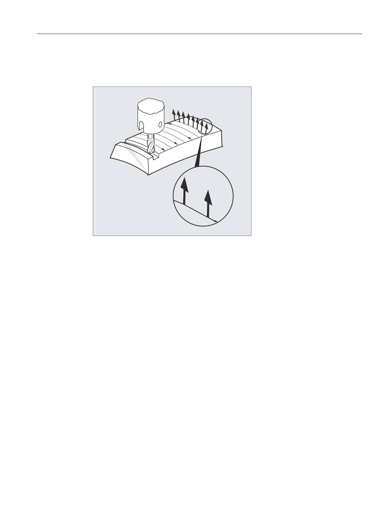
Transformations
7.2 Three, four and five axis transformation (TRAORI)
7.2.5
Face milling (A4, B4, C4, A5, B5, C5)
Face milling is used to machine curved surfaces of any kind.
$
%
$
&
%
&
For this type of 3D milling, you will require the line-by-line description of the 3D paths on the
workpiece surface.
The tool shape and dimensions are taken into account in the calculations, which are normally
performed in CAM. The fully calculated NC blocks are then read into the control via
postprocessors.
Programming the path curvature
Surface description
The path curvature is described by surface normal vectors with the following components:
A4, B4, C4 Start vector at block start
A5, B5, C5 End vector at block end
If a block only contains the start vector, the surface normal vector will remain constant
throughout the block. If a block only contains the end vector, interpolation will run from the end
value of the previous block via large-circle interpolation to the programmed end value.
If the start and end vectors are programmed, interpolation runs between the two directions,
also via large-circle interpolation. This allows continuously smooth paths to be created.
Regardless of the active G17 to G19 level, in the initial setting, surface normal vectors point
in the Z direction.
The length of a vector is meaningless.
Vector components that have not been programmed are set to zero.
Job Planning
Programming Manual, 12/2018, A5E40869460B AB
333
Transformations
7.2 Three, four and five axis transformation (TRAORI)
When ORIWKS is active (see "Reference of the orientation axes (ORIWKS, ORIMKS):
(Page 334)"), the surface normal vectors refer to the active frame and are also rotated with
frame rotation.
Machine manufacturer
The surface normal vector must be perpendicular to the path tangent, within a limit value set
via machine data, otherwise an alarm will be output.
7.2.6
Reference of the orientation axes (ORIWKS, ORIMKS):
For orientation programming in the workpiece coordinate system using
● Euler or RPY angle or
● Orientation vector
the course of the rotary motion can be set using ORIMKS/ORIWKS.
Note
Machine manufacturer
The type of interpolation for the orientation is specified with machine data:
MD21104 $MC_ORI_IPO_WITH_G_CODE
= FALSE: The reference is provided by the G commands ORIWKS und ORIMKS.
= TRUE: The reference are the G commands of the 51th group (ORIAXES, ORIVECT,
ORIPLANE, ...)
Syntax
ORIMKS=...
ORIWKS=...
Meaning
ORIMKS:
Rotation in the machine coordinate system
ORIWKS:
Rotation in the workpiece coordinate system
Note
ORIWKS is the basic setting. In the case of a 5-axis program, if it is not immediately obvious
on which machine it is to run, ORIWKS must always be selected. Which movements the
machine actually executes depend on the machine kinematics.
ORIMKS can be used to program actual machine movements (to avoid collisions with devices
or similar, for example).
Job Planning
334
Programming Manual, 12/2018, A5E40869460B AB
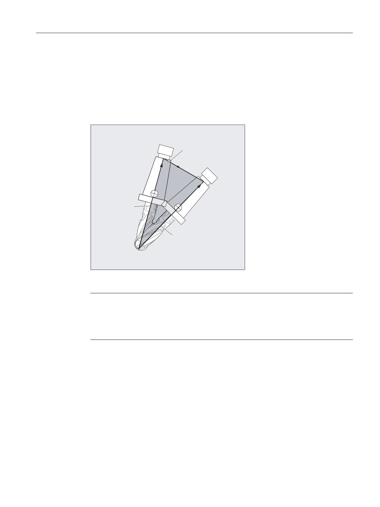
Transformations
7.2 Three, four and five axis transformation (TRAORI)
Further information
With ORIMKS, the movement executed by the tool depends on the machine kinematics. In the
case of a change in orientation of a tool tip at a fixed point in space, linear interpolation takes
place between the rotary axis positions.
With ORIWKS, the movement executed by the tool does not depend on the machine kinematics.
With an orientation change with a fixed tool tip, the tool moves in the plane set up by the start
and end vectors.
3ODQH WKDW ERWK
YHFWRUV FRYHUV
9HFWRU DW
EORFN VWDUW
9HFWRU DW EORFN HQG
Singular positions
Note
ORIWKS
Orientation movements in the singular setting area of the 5-axis machine require vast
movements of the machine axes. (For example, with a rotary swivel head with C as the rotary
axis and A as the swivel axis, all positions with A = 0 are singular.)
Machine manufacturer
To avoid overloading the machine axes, the velocity control vastly reduces the tool path velocity
near the singular positions.
With machine data
$MC_TRAFO5_NON_POLE_LIMIT
$MC_TRAFO5_POLE_LIMIT
the transformation can be parameterized in such a way that orientation movements close to
the pole are put through the pole and rapid machining is possible.
Singular positions are handled only with the MD $MC_TRAFO5_POLE_LIMIT.
Job Planning
Programming Manual, 12/2018, A5E40869460B AB
335

Transformations
7.2 Three, four and five axis transformation (TRAORI)
References:
/FB3/ Function Manual, Special Functions; 3- to 5-Axis Transformation (F2),
"Singular Points and How to Deal with Them" section.
7.2.7
Programming orientation axes (ORIAXES, ORIVECT, ORIEULER, ORIRPY,
ORIRPY2, ORIVIRT1, ORIVIRT2)
The "Orientation axes" function describes the orientation of the tool in space and is achieved
by programming the offset for the rotary axes. An additional, third degree of freedom can be
achieved by also rotating the tool about itself. In this case, the tool is oriented in space via a
third rotary axis for which 6-axis transformation is required. The rotation of the tool about itself
is defined using the THETA angle of rotation in accordance with the type of interpolation of the
rotation vectors (see "Rotations of the tool orientation (ORIROTA, ORIROTR, ORIROTT,
ORIROTC, THETA) (Page 346)").
Axis identifiers A2, B2 and C2 are used to program the orientation axes.
Syntax
N... ORIAXES/ORIVECT
; Linear or large-circle interpolation
N... G1 X Y Z A B C
N... ORIPLANE
; Orientation interpolation of the plane
N... ORIEULER/ORIRPY/ORIRPY2
: Orientation angle Euler/RPY angle
N... G1 X Y Z A2= B2= C2=
; Angle programming of virtual axes
N... ORIVIRT1/ORIVIRT2
; Virtual orientation axes def. 1/2
N... G1 X Y Z A3= B3= C3=
; Direction vector programming
Note
Other rotary axis offsets of the orientation axes can be programmed for orientation changes
along the peripheral surface of a taper in space, see "Orientation programming along the
peripheral surface of a taper (ORIPLANE, ORICONCW, ORICONCCW, ORICONTO,
ORICONIO) (Page 338)".
Meaning
ORIAXES:
Linear interpolation of machine or orientation axes
ORIVECT:
Large-circle interpolation (identical to ORIPLANE)
ORIMKS:
Rotation in the machine coordinate system
ORIWKS:
Rotation in the workpiece coordinate system
For a description, see "Reference of the orientation axes (ORIWKS,
ORIMKS): (Page 334)".
A= B= C=:
Programming the machine axis position
Job Planning
336
Programming Manual, 12/2018, A5E40869460B AB

Transformations
7.2 Three, four and five axis transformation (TRAORI)
ORIEULER:
Orientation programming via Euler angle
ORIRPY:
Orientation programming via RPY angle
The rotation sequence is XYZ and:
● A2 is the angle of rotation around X
● B2 is the angle of rotation around Y
● C2 is the angle of rotation around Z
ORIRPY2:
Orientation programming via RPY angle
The rotation sequence is ZYX and:
● A2 is the angle of rotation around Z
● B2 is the angle of rotation around Y
● C2 is the angle of rotation around X
A2= B2= C2=:
Angle programming of virtual axes
ORIVIRT1/ORIVIRT2:
Orientation programming using virtual orientation axes
Definition 1:
Definition according to MD21120 $MC_ORIAX_TURN_TAB_1
Definition 2:
Definition according to MD21130 $MC_ORIAX_TURN_TAB_2
A3= B3= C3=:
Direction vector programming of direction axis
Further information
Machine manufacturer
MD21102 $MC_ORI_DEF_WITH_G_CODE specifies how the programmed angles A2, B2, C2
are defined:
The definition is according to MD21100 $MC_ORIENTATION_IS_EULER (standard) or the
definition is according to G group 50 (ORIEULER, ORIRPY, ORIVIRT1, ORIVIRT2).
MD21104 $MC_ORI_IPO_WITH_G_CODE defines which interpolation mode type is active:
ORIWKS/ORIMKS or ORIAXES/ORIVECT.
JOG mode
Interpolation for orientation angles in this mode of operation is always linear. During continuous
and incremental traversal via the traversing keys, only one orientation axis can be traversed.
Orientation axes can be traversed simultaneously using the handwheels.
When orientation axes are traversed manually, the channel-specific feedrate override switch
or the rapid traverse override switch in rapid traverse override is applied.
A separate velocity setting is possible with the following machine data:
MD21160 $MC_JOG_VELO_RAPID_GEO
MD21165 $MC_JOG_VELO_GEO
MD21150 $MC_JOG_VELO_RAPID_ORI
Job Planning
Programming Manual, 12/2018, A5E40869460B AB
337
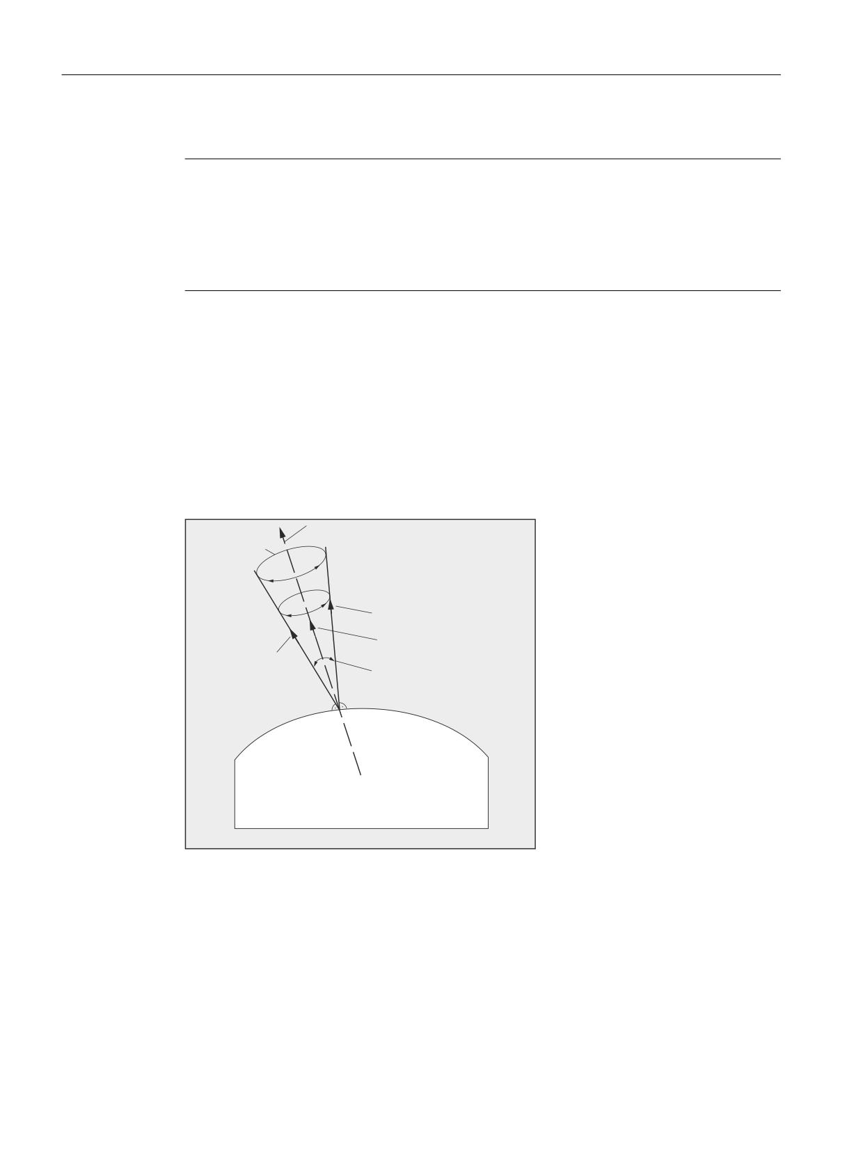
Transformations
7.2 Three, four and five axis transformation (TRAORI)
MD21155 $MC_JOG_VELO_ORI
Note
SINUMERIK 840D sl with "handling transformation package"
Using the "Cartesian manual traverse" function, the translation of geometry axes in JOG mode
can be set separately from one another in the reference systems MCS, WCS and TCS.
References:
Function Manual Extended Functions; Kinematic Transformation (M1)
7.2.8
Orientation programming along the peripheral surface of a taper (ORIPLANE,
ORICONCW, ORICONCCW, ORICONTO, ORICONIO)
With extended orientation it is possible to execute a change in orientation along the peripheral
surface of a taper in space. The orientation vector is interpolated on the peripheral surface of
a taper using the ORICONxx modal command. The end orientation can be programmed with
ORIPLANE for interpolation on a plane. The start orientation is usually defined by the previous
blocks.
'LUHFWLRQ D[LV
$QJOH RI
URWDWLRQ
3+,
25,&21&&:
FRXQWHU FORFNZLVH
25,&21&:
(QG RULHQWDWLRQ
FORFNZLVH
,QWHUPHGLDWH RULHQWDWLRQ
6WDUW RULHQWDWLRQ
GHWHUPLQHG E\
2SHQLQJ DQJOH 36,
SUHYLRXV EORFN
RI WDSHU
:RUNSLHFH
VXUIDFH
Job Planning
338
Programming Manual, 12/2018, A5E40869460B AB

Transformations
7.2 Three, four and five axis transformation (TRAORI)
Programming
The end orientation is either defined by specifying the angle programming in the Euler or RPY
angle using A2, B2, C2 or by programming the rotary axis positions using A, B, C. Further
programming details are needed for orientation axes along the peripheral surface of a taper:
● Rotary axis of taper as a vector with A6, B6, C6
● Opening angle PSI with identifier NUT
● Intermediate orientation outside of the taper with A7, B7, C7
Note
Programming direction vector A6, B6, C6 for the rotary axis of the taper
The programming of an end orientation is not absolutely necessary. If no end orientation
is specified, a full outside taper with 360 degrees is interpolated.
Programming the opening angle of the taper with NUT=angle
An end orientation must be specified.
A complete outside taper with 360 degrees cannot be interpolated in this way.
Programming the intermediate orientation A7, B7, C7 on the outside of the taper
An end orientation must be specified. The change in orientation and the direction of rotation
is defined uniquely by the three vectors Start orientation, End orientation and Intermediate
orientation. All three vectors must be different. If the programmed intermediate orientation
is parallel to the start or end orientation, a linear large-circle interpolation of the orientation
is executed in the plane that is defined by the start and end vector.
Extended orientation interpolation on the peripheral surface of a taper
N... ORICONCW or ORICONCCW
Interpolation on the outside of a taper with
N... A6= B6= C6= A3= B3= C3=
direction vector in the clockwise/counter-
clockwise direction of the taper and end ori-
or
entation or
N... ORICONTO
tangential transition and
N... G1 X Y Z A6= B6= C6=
specification of end orientation
or
or
N... ORICONIO
specification of end orientation and
N... G1 X Y Z A7= B7= C7=
intermediate orientation on the outside of
the taper with
N... PO[PHI]=(a2, a3, a4, a5)
polynomials for angle of rotation and
N... PO[PSI]=(b2, b3, b4, b5)
polynomials for opening angle
Parameters
ORIPLANE:
Interpolation in the plane (large-circle interpolation)
ORICONCW:
Interpolation on the peripheral surface of a taper in the clockwise di-
rection
ORICONCCW:
Interpolation on the peripheral surface of a taper in the counter-clock-
wise direction
Job Planning
Programming Manual, 12/2018, A5E40869460B AB
339
Transformations
7.2 Three, four and five axis transformation (TRAORI)
ORICONTO:
Interpolation on the peripheral surface of a taper with tangential tran-
sition
A6= B6= C6=:
Programming of a rotary axis of the taper (normalized vector)
NUT=angle:
Opening angle of taper in degrees
NUT=+179:
Traverse angle less than or equal to 180 degrees
NUT=-181:
Traverse angle greater than or equal to 180 degrees
ORICONIO:
Interpolation on the peripheral surface of a taper
A7= B7= C7=:
Intermediate orientation (programming as normalized vector)
PHI:
Angle of rotation of the orientation about the direction axis of the taper
PSI:
Opening angle of the taper
Possible polynomials
Apart from the different angles, polynomials can also be programmed
PO[PHI]=(a2, a3, a4, a5)
up to the
PO[PSI]=(b2, b3, b4, b5)
5th degree
Example: Different changes to orientation
Program code
Comment
…
N10 G1 X0 Y0 F5000
N20 TRAORI(1)
; Orientation transformation ON
N30 ORIVECT
; Interpolate tool orientation as a vec-
tor.
…
; Tool orientation in the plane.
N40 ORIPLANE
; Select large-circle interpolation.
N50 A3=0 B3=0 C3=1
N60 A3=0 B3=1 C3=1
; Orientation in the Y/Z plane is rota-
ted through 45 degrees, orientation (0,1/
√2,1/√2) is reached at the end of the
block.
…
N70 ORICONCW
; Orientation programming on the outside
of the taper:
N80 A6=0 B6=0 C6=1 A3=0 B3=0 C3=1
The orientation vector is interpolated
on the outside of a taper with the direc-
tion (0,0,1) up to the orientation (1/
√2,0,1/√2) in the clockwise sense, the
angle of rotation is 270 degrees.
N90 A6=0 B6=0 C6=1
; The tool orientation goes through a
full revolution on the outside of the
same taper.
Further information
If changes of orientation along the peripheral surface of a taper anywhere in space are to be
described, the vector about which the tool orientation is to be rotated must be known. The start
and end orientation must also be specified. The start orientation results from the previous block
and the end orientation has to be programmed or defined via other conditions.
Job Planning
340
Programming Manual, 12/2018, A5E40869460B AB
Transformations
7.2 Three, four and five axis transformation (TRAORI)
Programming in the ORIPLANE plane corresponds to ORIVECT
The programming of large-radius circular interpolation together with angle polynomials
corresponds to the linear and polynomial interpolation of contours. The tool orientation is
interpolated in a plane that is defined by the start and end orientation. If additional polynomials
are programmed, the orientation vector can also be tilted out of the plane.
Programming of circles in a plane G2/G3, CIP and CT
The extended orientation corresponds to the interpolation of circles in a plane. For the
corresponding programming options for circles with centers or radii such as G2/G3, circle via
intermediate point CIP and tangential circles CT, see
References: Programming Manual Fundamentals, "Programming motion commands".
Orientation programming
Interpolation of the orientation vector on the peripheral surface of a taper ORICONxx
Four different types of interpolation from G group 51 can be selected for interpolating
orientations on the peripheral surface of a taper:
1. Interpolation on the outside of a taper in the clockwise direction ORICONCW with
specification of end orientation and taper direction, or opening angle. The direction vector
is programmed with identifiers A6, B6, C6 and the opening angle of the taper with
identifier NUT= value range in interval 0 degrees to 180 degrees.
2. Interpolation on the outside of a taper in the counterclockwise direction ORICONCCW with
specification of end orientation and taper direction, or opening angle. The direction vector
is programmed with identifiers A6, B6, C6 and the opening angle of the taper with
identifier NUT= value range in interval 0 degrees to 180 degrees.
3. Interpolation on the outside of a taper ORICONIO with specification of end orientation and
an intermediate orientation, which is programmed with identifiers A7, B7, C7.
4. Interpolation on the outside of a taper ORICONTO with tangential transition and specification
of end orientation. The direction vector is programmed with identifiers A6, B6, C6.
7.2.9
Specification of orientation for two contact points (ORICURVE, PO[XH]=,
PO[YH]=, PO[ZH]=)
Programming the change in orientation using the second curve in space ORICURVE
Another way to program changes in orientation, besides using the tool tip along a curve in
space, is to program the motion of a second contact point of the tool using ORICURVE. In this
way, changes in tool orientation can be defined uniquely, as when programming the tool vector
itself.
Machine manufacturer
Please refer to the machine manufacturer's notes on axis identifiers that can be set via machine
data for programming the 2nd orientation path of the tool.
Job Planning
Programming Manual, 12/2018, A5E40869460B AB
341
Transformations
7.2 Three, four and five axis transformation (TRAORI)
Programming
This type of interpolation can be used to program points (using G1) or polynomials (using
POLY) for the two curves in space. Circles and involutes are not permitted. A BSPLINE spline
interpolation and the "Combine short spline blocks" function can also be activated.
References:
Function Manual, Basic Functions; Continuous-Path Mode, Exact Stop, Look Ahead (B1),
Section: Combine short spline blocks
The other spline types, ASPLINE and CSPLINE, and compressor activation using COMPON,
COMPCURV or COMPCAD are not permitted.
The motion of the two contact points of the tool can be predefined up to the 5th degree when
programming the orientation polynomials for coordinates.
Extended orientation interpolation with additional curve in space and polynomials for coordi-
nates
N... ORICURVE
Specification of the motion of the second
contact point of the tool and additional pol-
N... PO[XH]=(xe, x2, x3, x4, x5)
ynomials of the coordinates in question
N... PO[YH]=(ye, y2, y3, y4, y5)
N... PO[ZH]=(ze, z2, z3, z4, z5)
Parameters
ORICURVE
Interpolation of the orientation specifying a movement
between two contact points of the tool.
XH YH ZH
Identifiers of the coordinates of the second contact
point of the tool of the additional contour as a curve in
space
Possible polynomials
Apart from using the appropriate end points, the curves
PO[XH]=(xe, x2, x3, x4,
in space can also be programmed using polynomials.
x5) PO[YH]=(ye, y2, y3,
y4, y5) PO[ZH]=(ze, z2,
z3, z4, z5)
xe, ye, ze
End points of the curve in space
xi, yi, zi
Coefficients of the polynomials up to the 5th degree
Job Planning
342
Programming Manual, 12/2018, A5E40869460B AB
Transformations
7.2 Three, four and five axis transformation (TRAORI)
Note
Identifiers XH YH ZH for programming a 2nd orientation path
The identifiers must be selected such that no conflict arises with the other identifiers or linear
axes
X Y Z axes
and rotary axes such as
A2 B2 C2 Euler angle or RPY angle
A3 B3 C3 direction vectors
A4 B4 C4 or A5 B5 C5 surface normal vectors
A6 B6 C6 rotation vectors or A7 B7 C7 intermediate point coordinates
or other interpolation parameters.
Job Planning
Programming Manual, 12/2018, A5E40869460B AB
343
Transformations
7.3 Orientation polynomials (PO[angle], PO[coordinate])
7.3
Orientation polynomials (PO[angle], PO[coordinate])
Irrespective of the polynomial interpolation from G group 1 that is currently active, two different
types of orientation polynomial can be programmed up to the 5th degree for a three-axis to
five-axis transformation.
1. Polynomials for angles: lead angle LEAD, tilt angle TILT
in relation to the plane that is defined by the start and end orientation.
2. Polynomials for coordinates: XH, YH, ZH of the second curve in space for the tool
orientation of a reference point on the tool.
With a 6-axis transformation, the rotation of rotation vector THT can be programmed with
polynomials up to the 5th degree for rotations of the tool itself, in addition to the tool orientation.
Syntax
Type 1 orientation polynomials for angles
N… PO[PHI]=(a2, a3, a4, a5)
3-axis to 5-axis transformation
N… PO[PSI]=(b2, b3, b4, b5)
Type 2 orientation polynomials for coordinates
N… PO[XH]=(xe, x2, x3, x4, x5)
Identifiers for the coordinates of the second
orientation path for tool orientation
N… PO[YH]=(ye, y2, y3, y4, y5)
N… PO[ZH]=(ze, z2, z3, z4, z5)
In both cases, with 6-axis transformations, a polynomial can also be programmed for the
rotation using
N… PO[THT]=(c2, c3, c4, c5)
Interpolation of the rotation relative to the path
or
Interpolation absolute, relative and tangential
N… PO[THT]=(d2, d3, d4, d5)
to the change of orientation
of the orientation vector. This is possible if the transformation supports a rotation vector with
an offset that can be programmed and interpolated using the THETA angle of rotation.
Meaning
PO[PHI]
Angle in the plane between start and end orientation
PO[PSI]
Angle describing the tilt of the orientation from the plane between start and end orien-
tation
PO[THT]
Angle of rotation created by rotating the rotation vector of one of the G commands of
group 54 that is programmed using THETA
PHI
Lead angle LEAD
PSI
Tilt angle TILT
THETA
Rotation about the tool direction in Z
Job Planning
344
Programming Manual, 12/2018, A5E40869460B AB
Transformations
7.3 Orientation polynomials (PO[angle], PO[coordinate])
PO[XH]
X coordinate of the reference point on the tool
PO[YH]
Y coordinate of the reference point on the tool
PO[ZH]
Z coordinate of the reference point on the tool
Further information
Orientation polynomials cannot be programmed:
● If ASPLINE, BSPLINE, CSPLINE spline interpolations are active.
Type 1 polynomials for orientation angles are possible for every type of interpolation except
spline interpolation, that is, linear interpolation with rapid traverse G00 or with feedrate G01
with polynomial interpolation using POLY and
circular/involute interpolation G02, G03, CIP, CT, INVCW and INCCCW
However, type 2 polynomials for orientation coordinates are only possible if
linear interpolation with rapid traverse G00 or with feedrate G01 or
polynomial interpolation with POLY is active.
● If the orientation is interpolated using ORIAXES axis interpolation. In this case, polynomials
can be programmed directly with PO[A] and PO[B] for orientation axes A and B.
Type 1 orientation polynomials with ORIVECT, ORIPLANE and ORICONxx
Only type 1 orientation polynomials are possible for large-radius circular interpolation and
interpolation outside of the taper with ORIVECT, ORIPLANE and ORICONxx.
Type 2 orientation polynomials with ORICURVE
If interpolation with the additional curve in space ORICURVE is active, the Cartesian
components of the orientation vector are interpolated and only type 2 orientation polynomials
are possible.
Job Planning
Programming Manual, 12/2018, A5E40869460B AB
345

Transformations
7.4 Rotations of the tool orientation (ORIROTA, ORIROTR, ORIROTT, ORIROTC, THETA)
7.4
Rotations of the tool orientation (ORIROTA, ORIROTR, ORIROTT,
ORIROTC, THETA)
If you also want to be able to change the orientation of the tools on machine types with movable
tools, program each block with end orientation. Depending on the machine kinematics you can
either program the orientation direction of the orientation axes or the direction of rotation of
orientation vector THETA. Different interpolation types can be programmed for these rotation
vectors:
● ORIROTA: Angle of rotation to an absolute direction of rotation.
● ORIROTR: Angle of rotation relative to the plane between the start and end orientation.
● ORIROTT: Angle of rotation relative to the change in the orientation vector.
● ORIROTC: Tangential angle of rotation to the path tangent.
Syntax
Only if interpolation type ORIROTA is active can the angle of rotation or rotation vector be
programmed in all four modes as follows:
1. Directly as rotary axis positions A, B, C
2. Euler angles (in degrees) with A2, B2, C2
3. RPY angles (in degrees) with A2, B2, C2
4. Direction vector via A3, B3, C3 (angle of rotation using THETA=<value>)
If ORIOTR or ORIOTT is active, the angle of rotation can only be programmed directly with
THETA.
A rotation can also be programmed in a separate block without an orientation change taking
place. In this case, ORIROTR and ORIROTT are irrelevant. In this case, the angle of rotation
is always interpreted with reference to the absolute direction (ORIROTA).
N... ORIROTA
Define the interpolation of the rotation vector
N... ORIROTR
N... ORIROTT
N... ORIROTC
N... A3= B3= C3= THETA=<value> Define the rotation of the orientation vector
N... PO[THT]=(d2, d3, d4, d5)
Interpolate angle of rotation with a 5th order polyno-
mial
Meaning
ORIROTA:
Angle of rotation to an absolute direction of rotation
ORIROTR:
Angle of rotation relative to the plane between the start and end orientation
ORIROTT:
Angle of rotation as a tangential rotation vector to the change of orientation
ORIROTC:
Angle of rotation as a tangential rotation vector to the path tangent
THETA:
Rotation of the orientation vector
Job Planning
346
Programming Manual, 12/2018, A5E40869460B AB

Transformations
7.4 Rotations of the tool orientation (ORIROTA, ORIROTR, ORIROTT, ORIROTC, THETA)
THETA=<value>:
Angle of rotation in degrees reached by the end of the block
THETA=Θe:
Angle of rotation with end angle Θe of rotation vector
THETA=AC(…):
Non-modal switchover to absolute dimensions
THETA=AC(…):
Non-modal switchover to incremental dimensions
Θe:
End angle of rotational vector both absolute with G90 and relative with G91
(incremental dimensioning) is active
PO[THT]=(
):
Polynomial for angle of rotation
Example: Rotations of the orientations
Program code
Comment
N10 TRAORI
; Activate orientation transformation
N20 G1 X0 Y0 Z0 F5000
; Tool orientation
N30 A3=0 B3=0 C3=1 THETA=0
; In Z direction with angle of rotation 0
N40 A3=1 B3=0 C3=0 THETA=90
;In X direction and rotation about 90 degrees
N50 A3=0 B3=1 C3=0 PO[THT]=(180,90)
;Orientation
N60 A3=0 B3=1 C3=0 THETA=IC(-90)
;In Y direction and rotation about 180 degrees
N70 ORIROTT
;Remains constant and rotation to 90 degrees
N80 A3=1 B3=0 C3=0 THETA=30
;Angle of rotation relative to change of ori-
entation
;Rotation vector in angle 30 degrees to X/Y
plane
When interpolating block N40, the angle of rotation from initial value of 0 degrees to final value
of 90 degrees is interpolated linearly. In block N50, the angle of rotation changes from 90
degrees to 180 degrees, according to parabola θ(u) = +90u2. In N60, a rotation can also be
executed without a change in orientation taking place.
With N80, the tool orientation is rotated from the Y direction toward the X direction. The change
in orientation takes place in the X/Y plane and the rotation vector describes an angle of 30
degrees to this plane.
Further information
ORIROTA
The angle of rotation THETA is interpolated with reference to an absolute direction in space.
The basic direction of rotation is defined in the machine data.
ORIROTR
The angle of rotation THETA is interpreted relative to the plane defined by the start and end
orientation.
ORIROTT
The angle of rotation THETA is interpreted relative to the change in orientation. For THETA=0
the rotation vector is interpolated tangentially to the change in orientation and only differs from
ORIROTR if at least one polynomial has been programmed for "tilt angle PSI" for the orientation.
The result is a change in orientation that is not executed in the plane. An additional angle of
Job Planning
Programming Manual, 12/2018, A5E40869460B AB
347
Transformations
7.4 Rotations of the tool orientation (ORIROTA, ORIROTR, ORIROTT, ORIROTC, THETA)
rotation THETA can then be used to interpolate the rotation vector such that it always produces
a specific value referred to the change in orientation.
ORIROTC
The rotation vector is interpolated relative to the path tangent with an offset that can be
programmed using the THETA angle. A polynomial PO[THT]=(c2, c3, c4, c5) up to
the 5th degree can also be programmed for the offset angle.
Job Planning
348
Programming Manual, 12/2018, A5E40869460B AB
Transformations
7.5 Orientations relative to the path
7.5
Orientations relative to the path
7.5.1
Orientation types relative to the path
By using this expanded function, relative orientation is not only achieved at the end of the
block, but across the entire trajectory. The orientation achieved in the previous block is
transferred to the programmed end orientation using large-circle interpolation. There are
basically two ways of programming the desired orientation relative to the path:
1. Like the tool rotation, the tool orientation is interpolated relative to the path using ORIPATH,
ORPATHTS.
2. The orientation vector is programmed and interpolated in the usual manner. The rotation
of the orientation vector is initiated relative to the path tangent using ORIROTC.
Syntax
The type of interpolation of the orientation and the rotation of the tool is programmed using:
N... ORIPATH
Orientation relative to the path
N... ORIPATHS
Orientation relative to the path with smoothing of orientation
characteristic
N... ORIROTC
Interpolation of the rotation vector relative to the path
An orientation blip caused by a corner on the trajectory can be smoothed using ORIPATHS.
The direction and path length of the retracting movement is programmed via the vector using
the components A8=X, B8=Y C8=Z.
ORIPATH/ORIPATHS can be used to program various references to the path tangent via the
three angles
● LEAD= Specification of lead angle relative to the path and surface
● TILT= Specification of tilt angle relative to the path and surface
● THETA= Angle of rotation
for the entire trajectory. Polynomials up to the 5th degree can be programmed in addition to
the THETA angle of rotation using PO[THT]=(...).
Note
Machine manufacturer
Please refer to the machine manufacturer's instructions. Other settings can be made for
orientations relative to the path via configurable machine and setting data. For more detailed
information, please refer to
References:
/FB3/ Function Manual, Special Functions; 3 to 5-Axis Transformation (F2),
Section "Orientation"
Job Planning
Programming Manual, 12/2018, A5E40869460B AB
349
Transformations
7.5 Orientations relative to the path
Meaning
Various settings can be made for the interpolation of angles LEAD and TILT via machine data:
● The tool-orientation reference programmed using LEAD and TILT is retained for the entire
block.
● Lead angle LEAD: rotation about the direction vertical to the tangent and normal vector
TILT: rotation of the orientation about the normal vector.
● Lead angle LEAD: rotation about the direction vertical to the tangent and normal vector Tilt
angle TILT: rotation of the orientation in the direction of the path tangent.
● Angle of rotation THETA: rotation of the tool about itself with an additional third rotary axis
acting as an orientation axis in 6-axis transformation.
Note
Orientation relative to the path not permitted in conjunction with OSC, OSS, OSSE, OSD
and OST
Orientation interpolation relative to the path, that is ORIPATH or ORIPATHS and ORIOTC,
cannot be programmed in conjunction with orientation characteristic smoothing with a G
command from group 34. OSOF has to be active for this.
7.5.2
Rotation of the tool orientation relative to the path (ORIPATH, ORIPATHS, angle
of rotation)
With a 6-axis transformation, the tool can be rotated about itself with a third rotary axis to
orientate the tool as desired in space. With a rotation of the tool orientation relative to the path
using ORIPATH or ORIPATHS, the additional rotation can be programmed via the THETA
angle of rotation. Alternatively, the LEAD and TILT angles can be programmed using a vector,
which is located in the plane vertical to the tool direction.
Machine manufacturer
Please refer to the machine manufacturer's instructions. The interpolation of the LEAD and
TILT angles can be set differently using machine data.
Syntax
Rotation of tool orientation and tool
The type of tool orientation relative to the path is activated using ORIPATH or ORIPATHS.
N... ORIPATH
Activate type of orientation relative to the path
N... ORIPATHS
Activate type of orientation relative to the path with
smoothing of the orientation characteristic
Activating the three angles that can be rotated:
N... LEAD=
Angle for the programmed orientation relative to the
surface normal vector
Job Planning
350
Programming Manual, 12/2018, A5E40869460B AB