SINUMERIK 840D sl. Training. Operate - Turning (2016-2020) - page 26
Example 1: Taper shaft
6.2 Program management / creating programs
6.2
Program management / creating programs
Operating sequences
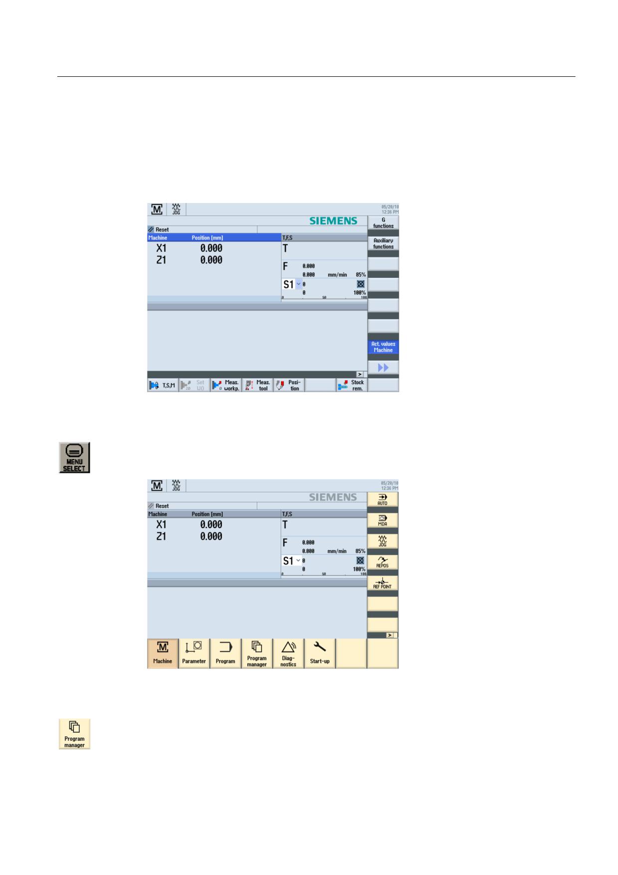
After power-up of the control system, you are in the main menu.
Figure 6-4
Main screen
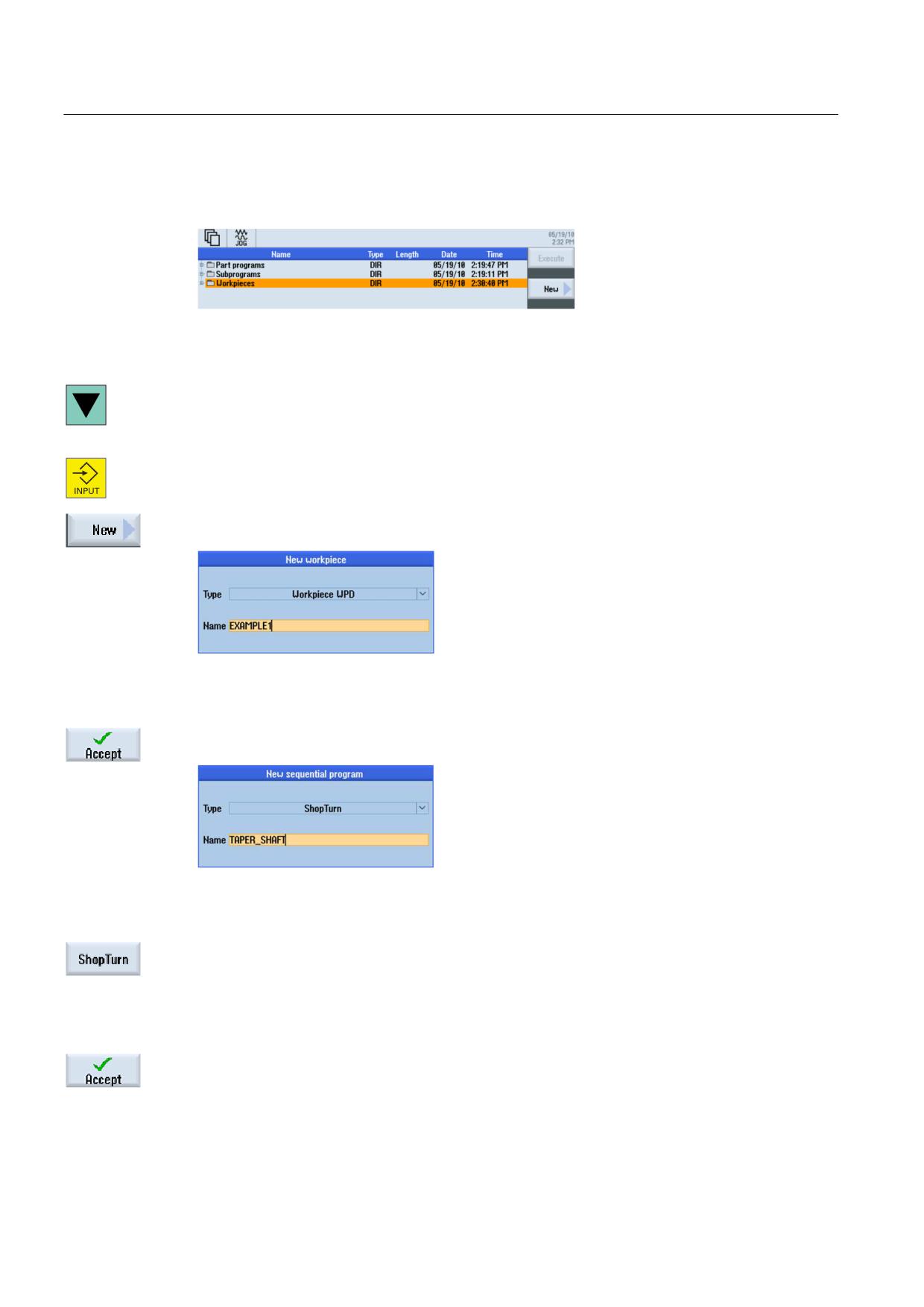
Open the main menu using the MENU SELECT key. You can call the various areas of
ShopTurn from the main menu.
Figure 6-5
Main menu
Select the Program Manager softkey. The Program Manager is opened.
Turning made easy with ShopTurn
Training Documents, 09/2011, 6FC5095-0AB80-1BP1
53
Example 1: Taper shaft
6.2 Program management / creating programs
In the Program Manager, you can manage process plans and contours (e.g. "New", "Open",
"Copy", ...).
Figure 6-6
Program Manager
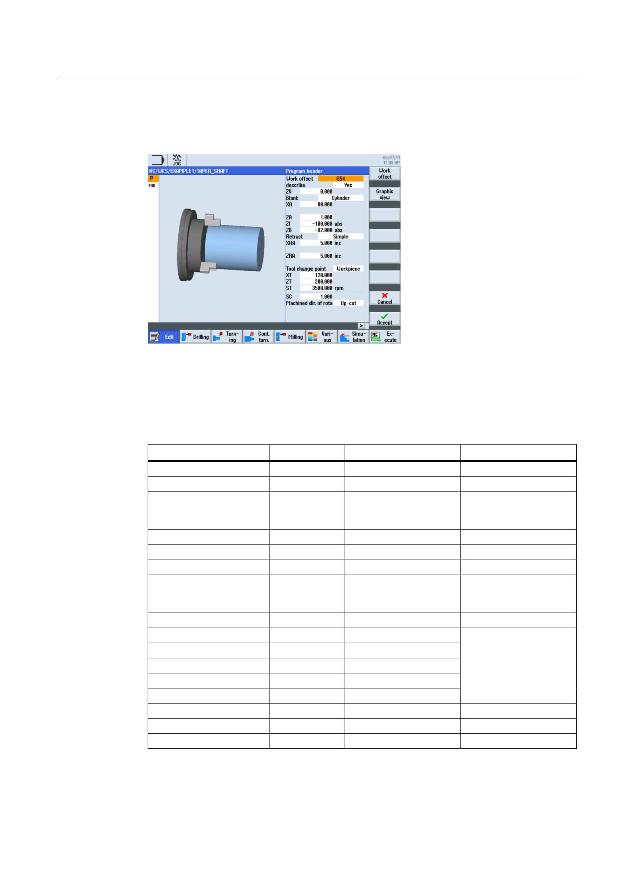
The Program Manager displays a list of the existing directories. Use the cursor key to select
the 'Workpieces' directory.
Open the "Workpieces" directory.
Enter the name 'EXAMPLE1' for the workpiece.
Figure 6-7
Creating a workpiece
Confirm your input. The following dialog box is opened:
Figure 6-8
Creating a step sequence program
Select the input format using the ShopTurn and ProgramGUIDE G code softkeys.
The program type can be specified via the ShopTurn softkey.
Specify the name of the process plan, in this case 'TAPER_SHAFT'.
Confirm your input.
Turning made easy with ShopTurn
54
Training Documents, 09/2011, 6FC5095-0AB80-1BP1
Example 1: Taper shaft
6.2 Program management / creating programs
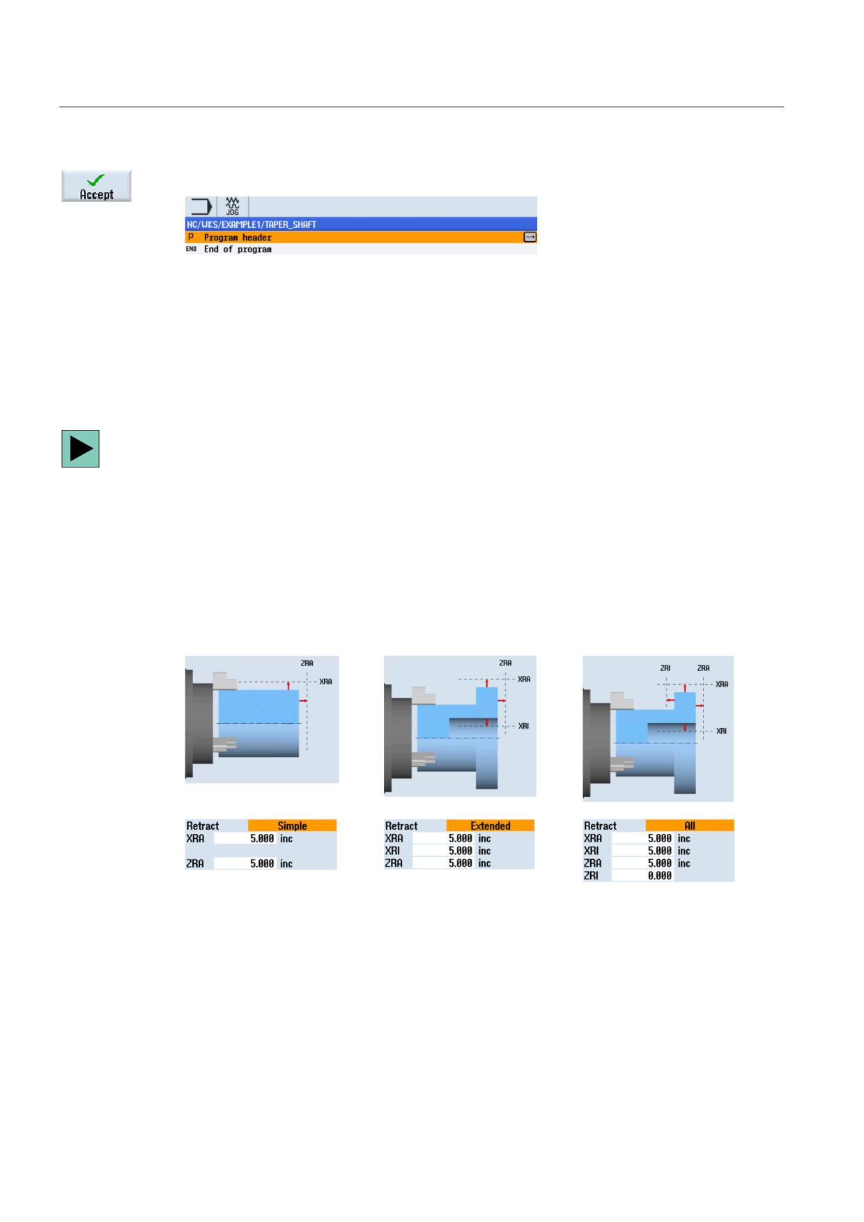
After confirming, the following interactive screenform is displayed to enter the workpiece
data.
Figure 6-9
Program header - Help display
Enter the workpiece data and general program specifications in the program header.
Enter the following values:
Field
Value
Selection via toggle key
Notes
Unit of measurement
mm
X
Work offset
X
Blank
Cylinder
X
Select the blank shape
(here cylinder) using the
toggle button.
XA
80
ZA
1
ZI
-100 abs
X
ZB
-92 abs
X
The value ZB indicates
the distance from the
chuck.
Retraction
normal
X
See below Retraction
XRA
5 inc
X
The dimensions of the
retraction planes
ZRA
5 inc
X
(absolute or incremental)
Tool change point
WCS
X
and the tool change point
XT
120
are entered here.
ZT
200
Safety clearance SC
1
Speed limits S1
3500
Machining direction
Synchronous
X
Turning made easy with ShopTurn
Training Documents, 09/2011, 6FC5095-0AB80-1BP1
55
Example 1: Taper shaft
6.2 Program management / creating programs
Accept the entered values. After confirming, the program header is displayed.
Figure 6-10 Program header, example 1 - Work step editor
Now the program has been created as the basis for further machining steps. It has a name
(in the blue bar), a program header (pictogram "P") and a program end (pictogram "END").
The individual machining steps and contours are stored in the program one beneath the
other. The later machining is performed from top to bottom.
You may call the program header again at any time to make changes or check the values.
Retraction
It is possible to switch the retraction plane between normal, extended and all. Depending on
the retraction setting, the associated fields are enabled for the input of the distances.
normal
extended
all
(for simple cylinders)
(for complex workpieces with
(for complex workpieces with
internal machining)
internal machining and/or relief
cuts)
Turning made easy with ShopTurn
56
Training Documents, 09/2011, 6FC5095-0AB80-1BP1
Example 1: Taper shaft
6.3 Calling a tool
Softkeys
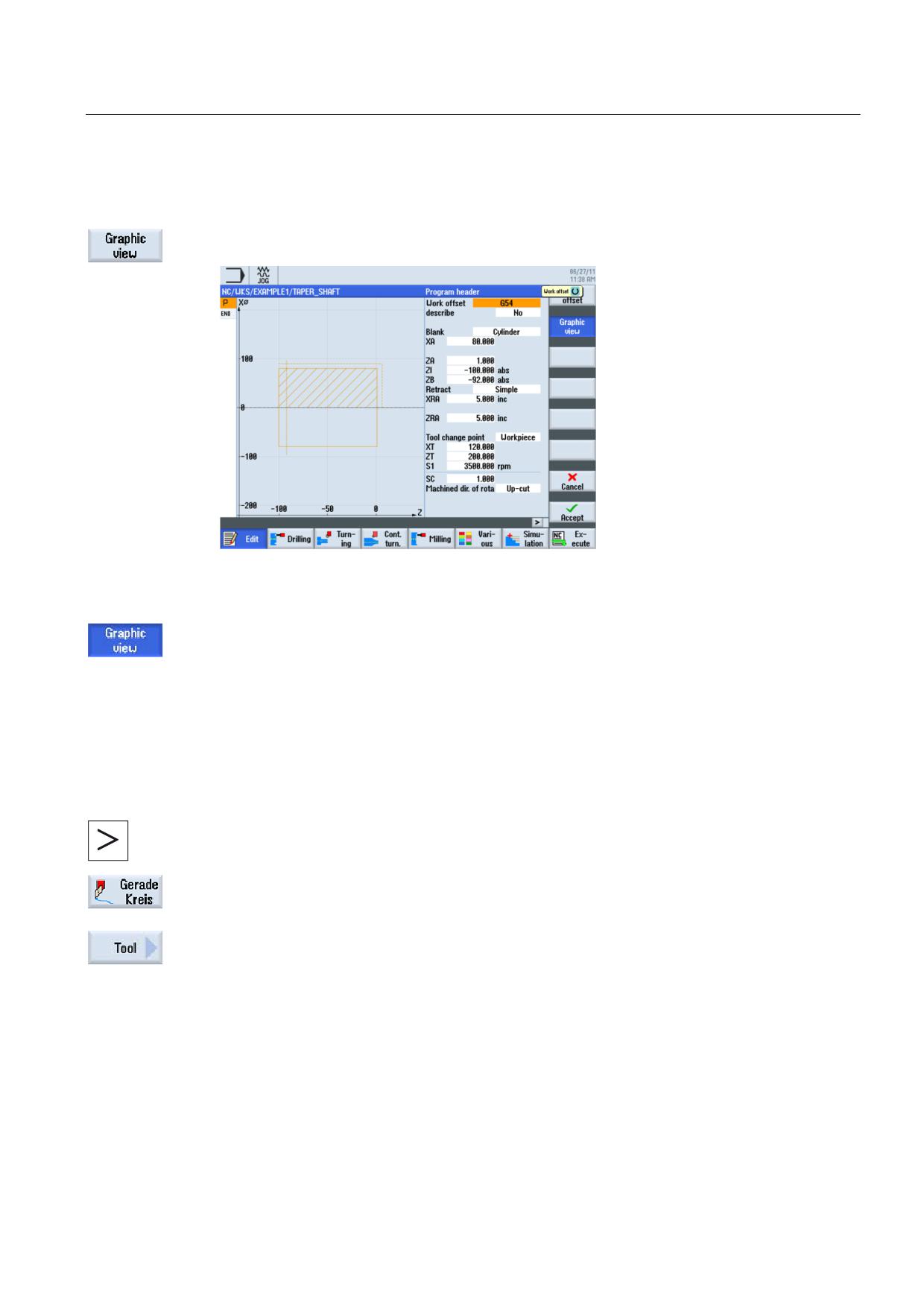
Use this softkey to switch to the online graphic of the workpiece (see screenform below).
Figure 6-11 Program header - graphical view
Use this softkey to switch back to the help display.
6.3
Calling a tool
Operating sequences
To call the required tool, proceed as follows:
Use this key to extend the horizontal softkey menu.
Select the Straight line Circle softkey.
Select the Tool softkey.
Turning made easy with ShopTurn
Training Documents, 09/2011, 6FC5095-0AB80-1BP1
57
Example 1: Taper shaft
6.3 Calling a tool
Open the tool list.
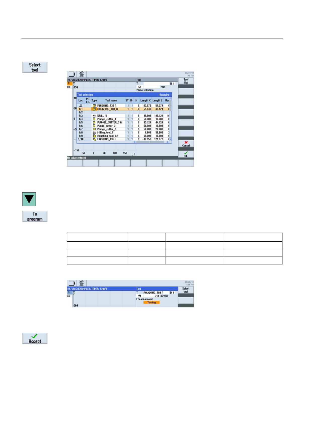
Figure 6-12 Tool list
Use the cursor key to select the ROUGHING_T80 A tool.
Accept the tool into your program. After accepting the tool, enter the following values in the
interactive screenform (if necessary, change the unit using the toggle key):
Field
Value
Selection via toggle key
Notes
Spindle
V1
X
Select main spindle V1.
Cutting rate
240 m/min
X
Plane selection
Turning
X
Figure 6-13 Tool - input
Accept the entered value.
Turning made easy with ShopTurn
58
Training Documents, 09/2011, 6FC5095-0AB80-1BP1
Example 1: Taper shaft
6.4 Specifying the distance to be traversed
6.4
Specifying the distance to be traversed
Operating sequences
Now enter the distances to be traversed:
Select the Straight line softkey.
Select the "Rapid traverse" softkey.
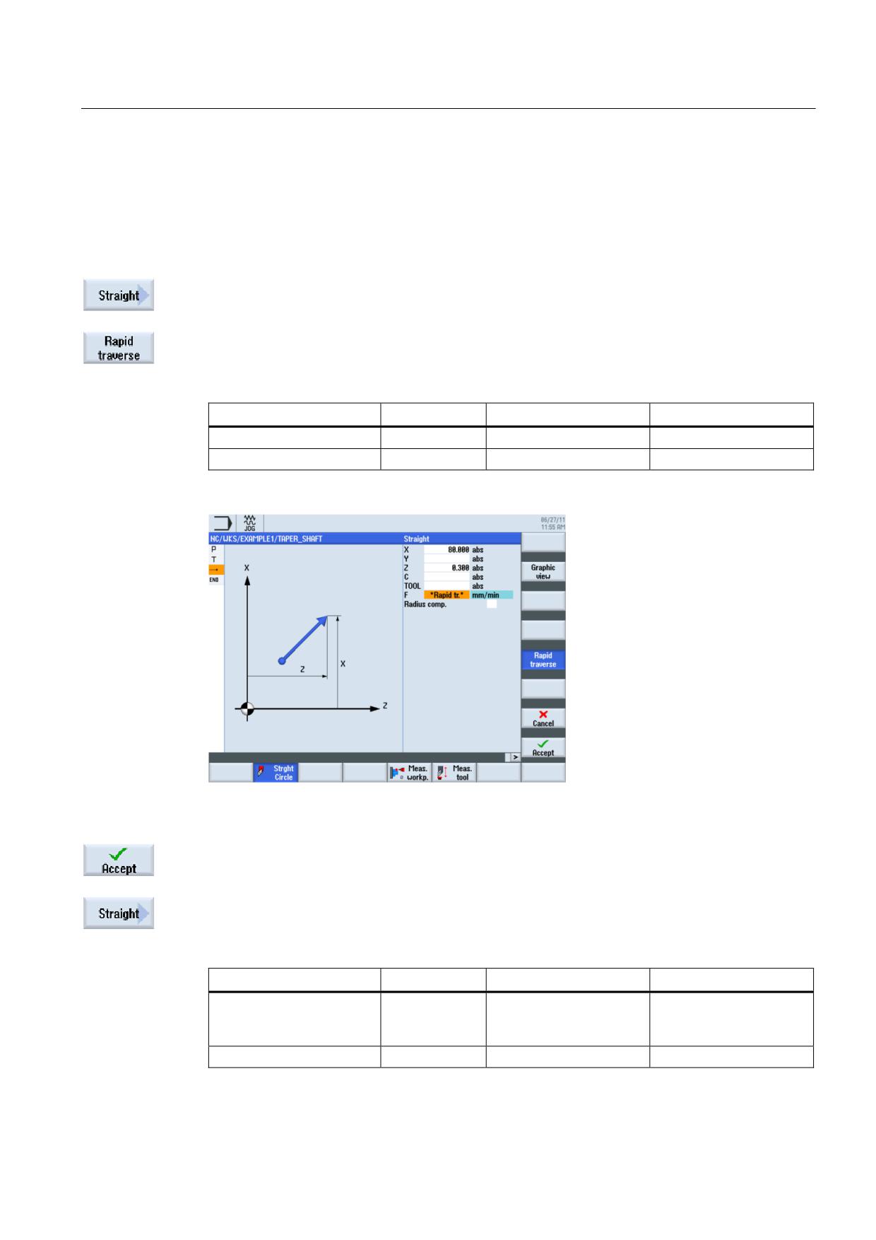
Enter the following starting point for roughing in the interactive screenform:
Field
Value
Selection via toggle key
Notes
X
82 abs
X
Z
0.3 abs
X
Enter the starting point for the traversing path
"Apply" the set values.
Select the Straight line softkey.
Enter the following values in the interactive screenform:
Field
Value
Selection via toggle key
Notes
X
-1.6 abs
X
The tool has a 0.8 radius,
so it must be traversed to
diameter X -1.6.
F
0.3 mm/rev
X
Turning made easy with ShopTurn
Training Documents, 09/2011, 6FC5095-0AB80-1BP1
59
Example 1: Taper shaft
6.4 Specifying the distance to be traversed
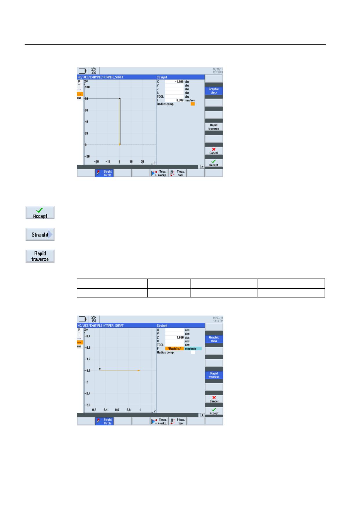
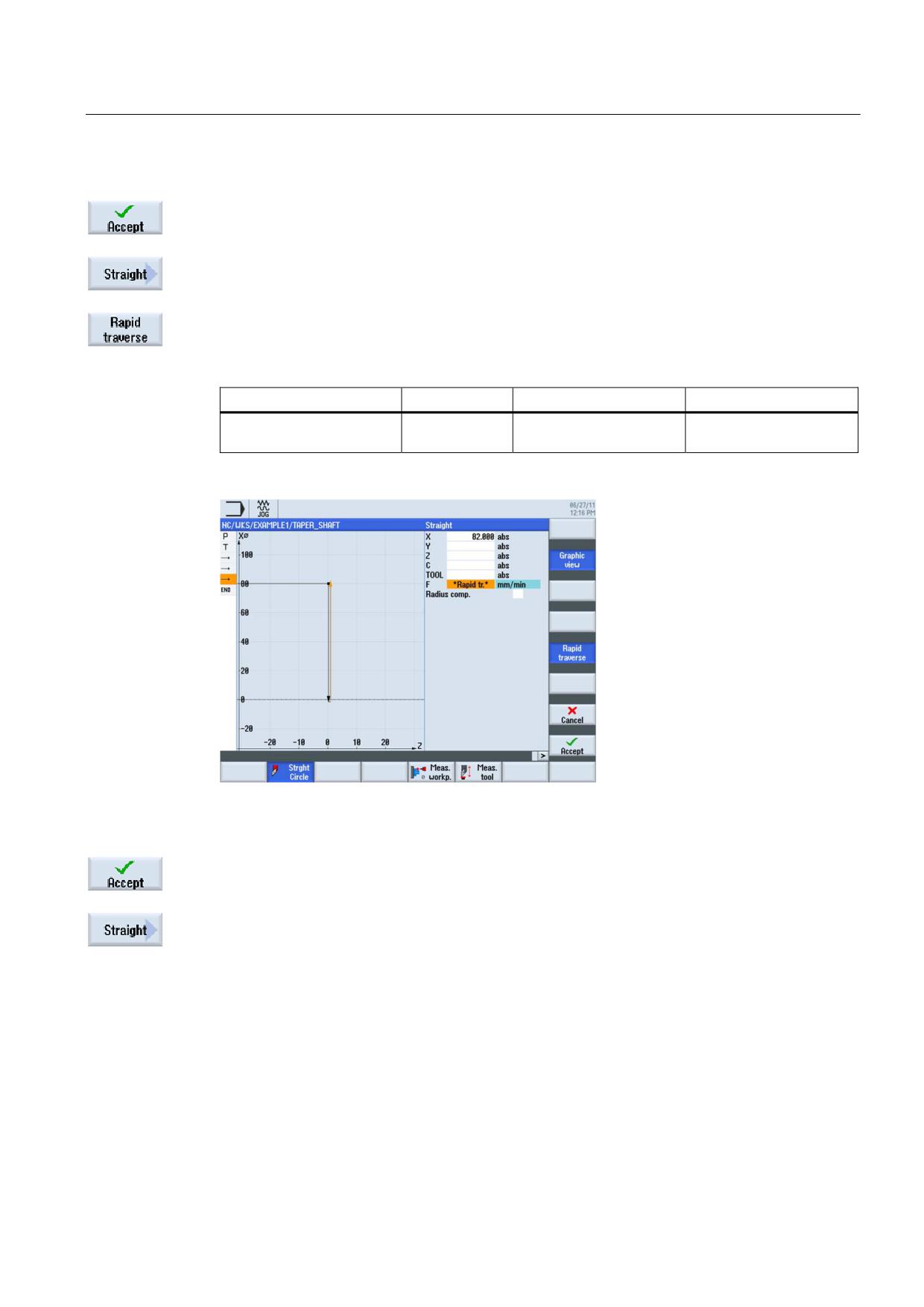
Figure 6-14 Specify the traversing path
"Apply" the set values.
Select the Straight line softkey.
Select the "Rapid traverse" softkey. Move the tool away from the end face in rapid traverse.
Enter the following values in the interactive screenform:
Field
Value
Selection via toggle key
Notes
Z
1 abs
X
Figure 6-15 Enter the traversing path - moving away from the end face
Turning made easy with ShopTurn
60
Training Documents, 09/2011, 6FC5095-0AB80-1BP1
Example 1: Taper shaft
6.4 Specifying the distance to be traversed
"Apply" the set values.
Select the Straight line softkey.
Select the "Rapid traverse" softkey.
Enter the following values in the interactive screenform:
Field
Value
Selection via toggle key
Notes
X
82 abs
X
This entry returns the tool
to the starting point.
Figure 6-16 Enter the traversing path - returning to the starting point
"Apply" the set values.
Select the Straight line softkey.
Turning made easy with ShopTurn
Training Documents, 09/2011, 6FC5095-0AB80-1BP1
61
Example 1: Taper shaft
6.4 Specifying the distance to be traversed
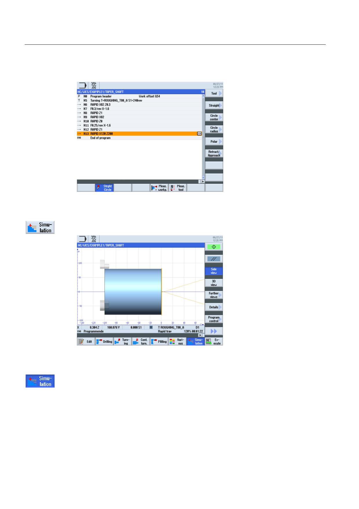
Create the four further traversing paths according to the following list of work steps.
Figure 6-17 Enter the traversing path - four further traversing paths
Start the simulation.
Figure 6-18 Simulation - side view
You may end simulation by selecting either the Simulation softkey again or any other
softkey.
Turning made easy with ShopTurn
62
Training Documents, 09/2011, 6FC5095-0AB80-1BP1
Example 1: Taper shaft
6.5 Creating contours with the contour calculator and machining sequence
6.5
Creating contours with the contour calculator and machining
sequence
Contour calculator
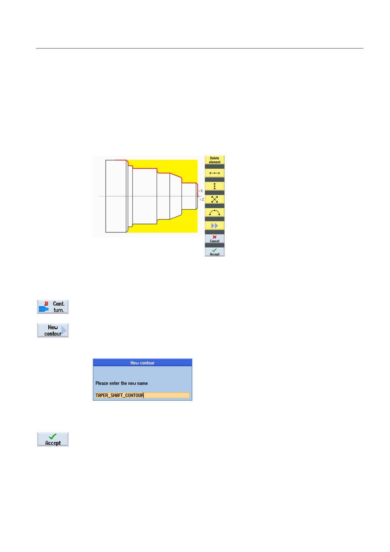
The integrated ShopTurn contour calculator allows you to enter even the most complicated
contours easily.
With the graphical contour calculator,
you can enter the contours faster and
more easily than with conventional
programming - and even without any
mathematical knowledge.
Operating sequences
Proceed as follows to enter the contour:
Select the Contour turning softkey.
Select the New contour softkey. Enter the name 'TAPER_SHAFT_CONTOUR' for the
contour.
Each contour is assigned its own name. This provides for better legibility of the programs.
Figure 6-19 Creating the 'TAPER_SHAFT_CONTOUR' contour
Confirm your input.
Turning made easy with ShopTurn
Training Documents, 09/2011, 6FC5095-0AB80-1BP1
63
Example 1: Taper shaft
6.5 Creating contours with the contour calculator and machining sequence
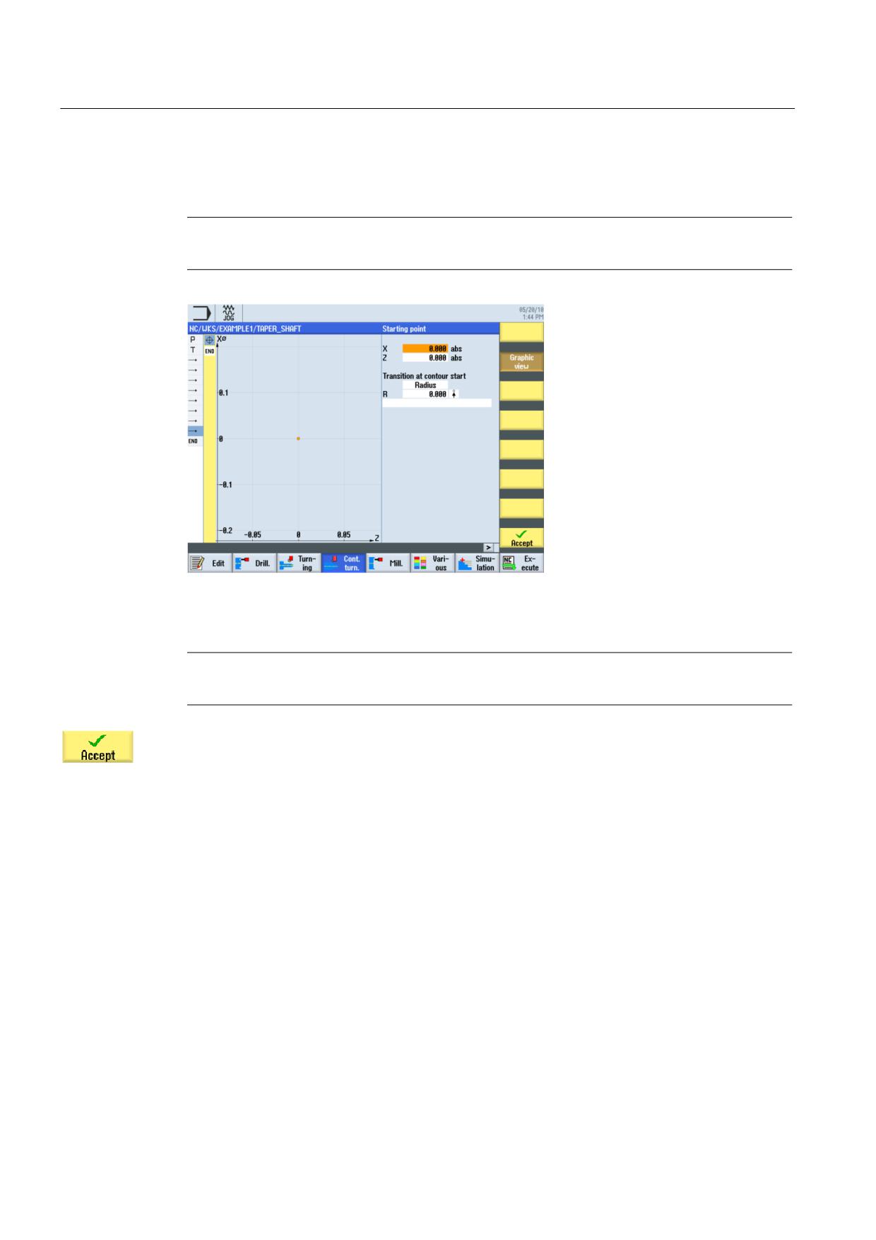
You can accept the starting point for the contour line without making any changes (see
illustration below).
Note
The contour line is in one sense the roughing limit and in another the finishing path.
Figure 6-20 Specifying the starting point
Note
If you deselect the Graphic view softkey, detailed help displays are shown.
Confirm your input.
Turning made easy with ShopTurn
64
Training Documents, 09/2011, 6FC5095-0AB80-1BP1
Example 1: Taper shaft
6.5 Creating contours with the contour calculator and machining sequence
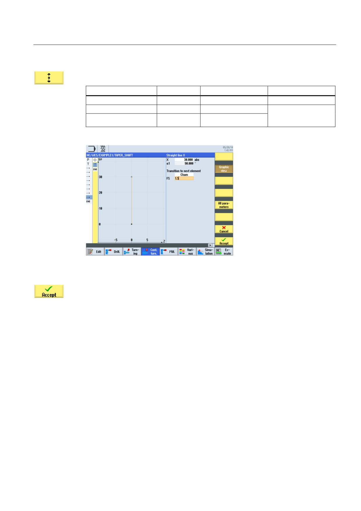
Enter the following values for the vertical straight line in the interactive screenform:
Field
Value
Selection via toggle key
Notes
X
30 abs
X
Transition to next element
Chamfer
X
Attach the chamfer (FS)
directly to the straight line
FS
1.5
as a transition element.
Figure 6-21 Specifying the vertical straight line contour
Accept the entered values.
Turning made easy with ShopTurn
Training Documents, 09/2011, 6FC5095-0AB80-1BP1
65
Example 1: Taper shaft
6.5 Creating contours with the contour calculator and machining sequence
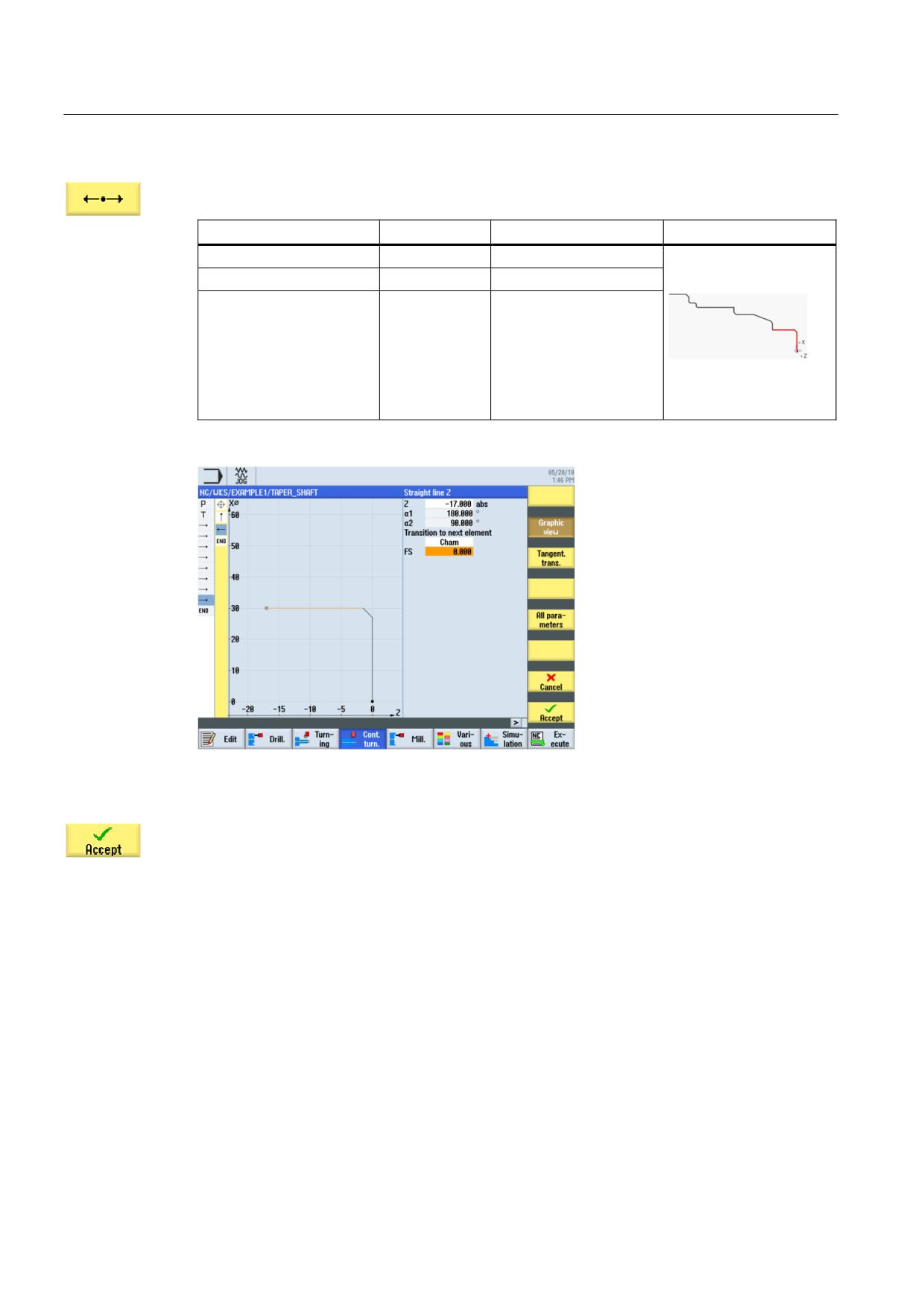
Enter the following values for the horizontal straight line in the interactive screenform:
Field
Value
Selection via toggle key
Notes
Z
-17 abs
X
A straight line appears up
to Z-17.
Transition to next element
Chamfer
X
FS
0
The thread undercut is
inserted later as an
individual element.
Figure 6-22 Specifying the horizontal straight line contour
Accept the entered values.
Turning made easy with ShopTurn
66
Training Documents, 09/2011, 6FC5095-0AB80-1BP1
Example 1: Taper shaft
6.5 Creating contours with the contour calculator and machining sequence
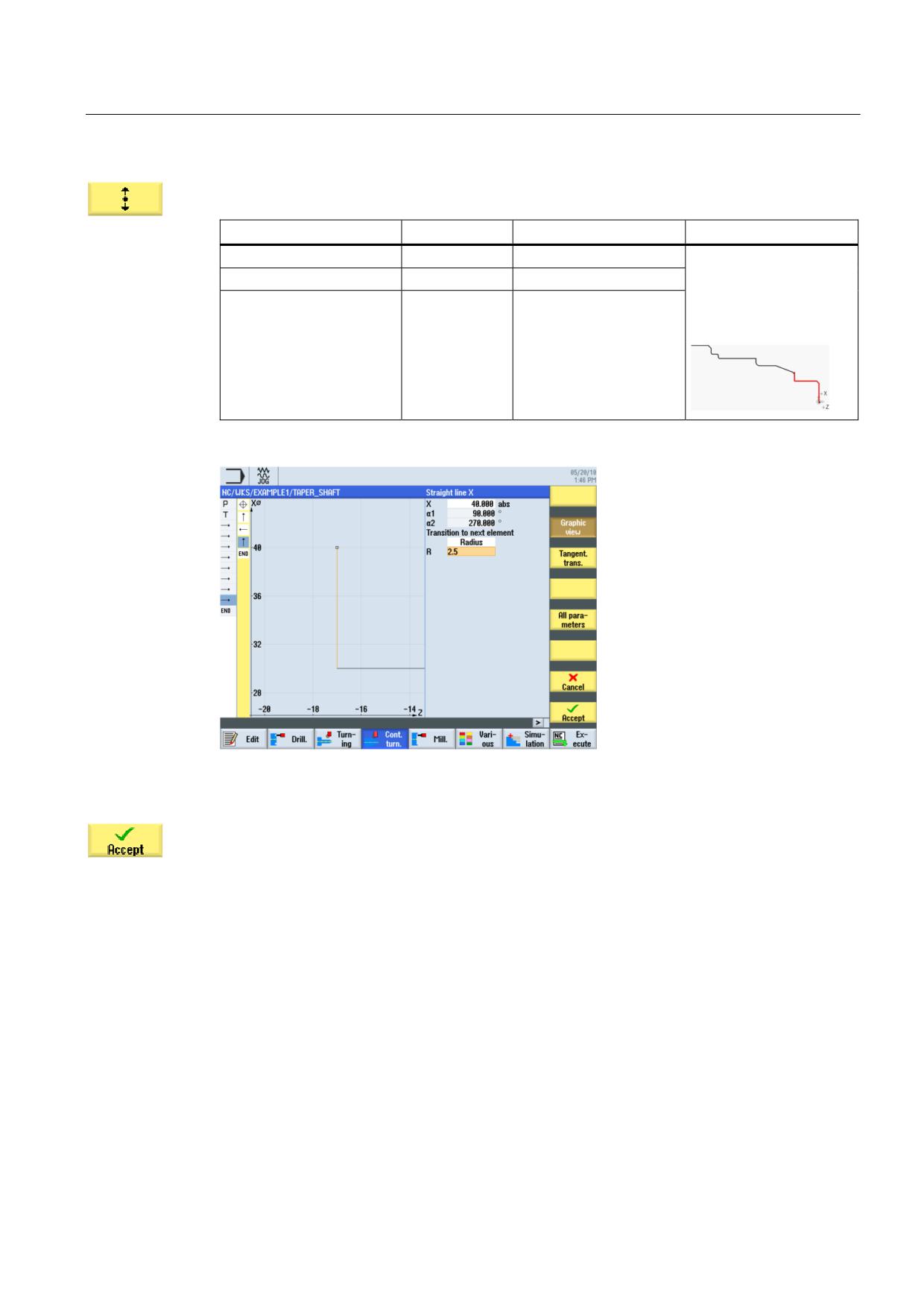
Enter the following value for the vertical straight line in the interactive screenform:
Field
Value
Selection via toggle key
Notes
X
40 abs
X
Draw the vertical straight
line up to the
Transition to next element
Radius
X
dimensioned intersection
R
2.5
including the rounding to
the next element.
Figure 6-23 Specifying the vertical straight line contour
Accept the entered values.
Turning made easy with ShopTurn
Training Documents, 09/2011, 6FC5095-0AB80-1BP1
67
Example 1: Taper shaft
6.5 Creating contours with the contour calculator and machining sequence
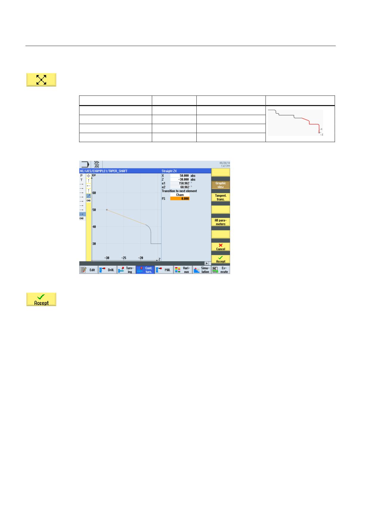
In the interactive screenform, enter the following values for the end point of the inclined
straight line:
Field
Value
Selection via toggle key
Notes
X
50 abs
X
Z
-30 abs
X
Transition to next element
Chamfer
X
FS
0
Figure 6-24 Specifying the contour end point of the inclined straight line
Accept the entered values.
Turning made easy with ShopTurn
68
Training Documents, 09/2011, 6FC5095-0AB80-1BP1
Example 1: Taper shaft
6.5 Creating contours with the contour calculator and machining sequence
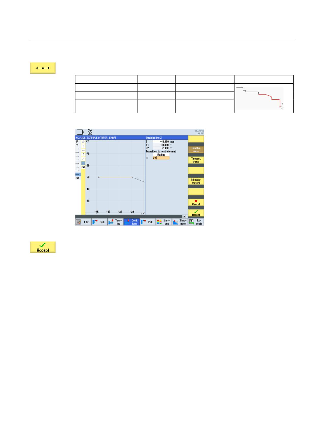
Enter the following values for the horizontal straight line in the interactive screenform:
Field
Value
Selection via toggle key
Notes
Z
-44 abs
X
Transition to next element
Radius
X
R
2.5
Figure 6-25 Specifying the horizontal straight line contour
Accept the entered values.
Turning made easy with ShopTurn
Training Documents, 09/2011, 6FC5095-0AB80-1BP1
69
Example 1: Taper shaft
6.5 Creating contours with the contour calculator and machining sequence
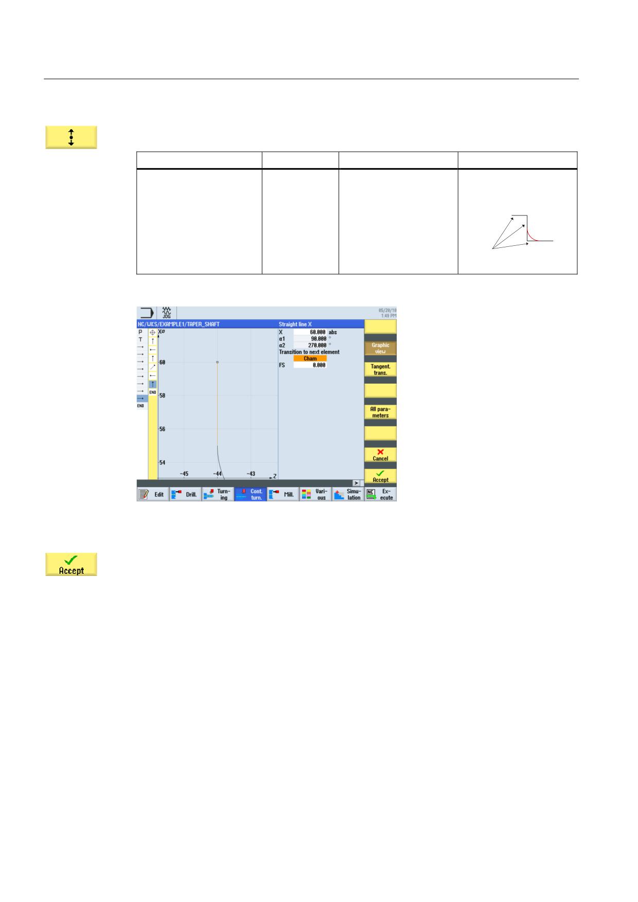
Enter the following values for the vertical straight line in the interactive screenform:
Field
Value
Selection via toggle key
Notes
X
60 abs
X
The paths (= main
elements) do not meet
tangentially.
5RXQGLQJ
PDLQ HOHPHQWV
Figure 6-26 Specifying the vertical straight line contour
Accept the entered values.
Turning made easy with ShopTurn
70
Training Documents, 09/2011, 6FC5095-0AB80-1BP1
Example 1: Taper shaft
6.5 Creating contours with the contour calculator and machining sequence
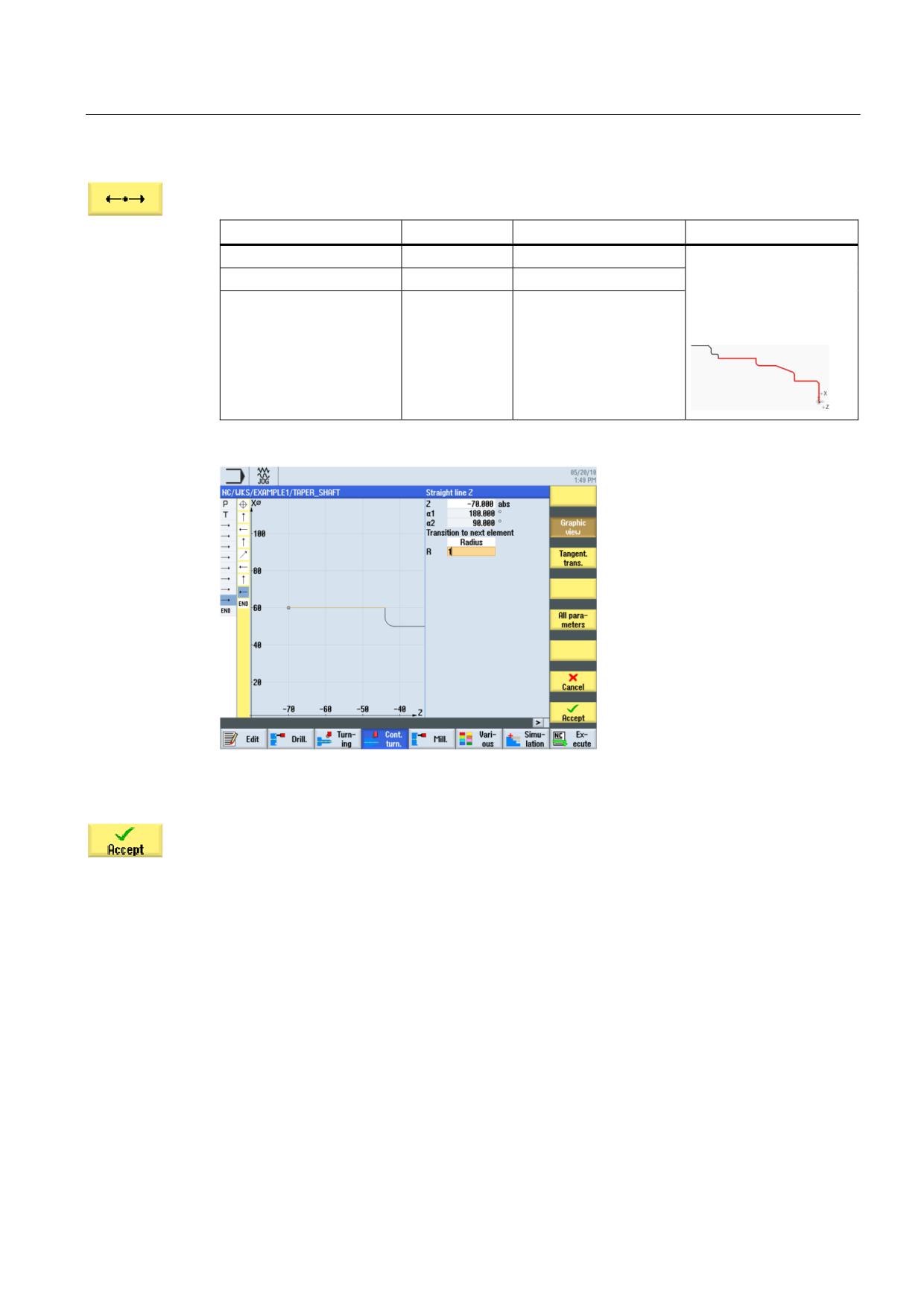
Enter the following values for the horizontal straight line in the interactive screenform:
Field
Value
Selection via toggle key
Notes
Z
-70 abs
X
The grooves are entered
later as individual
Transition to next element
Radius
X
elements in exactly the
R
1
same way as the thread
undercut.
Figure 6-27 Specifying the horizontal straight line contour
Accept the entered values.
Turning made easy with ShopTurn
Training Documents, 09/2011, 6FC5095-0AB80-1BP1
71
Example 1: Taper shaft
6.5 Creating contours with the contour calculator and machining sequence
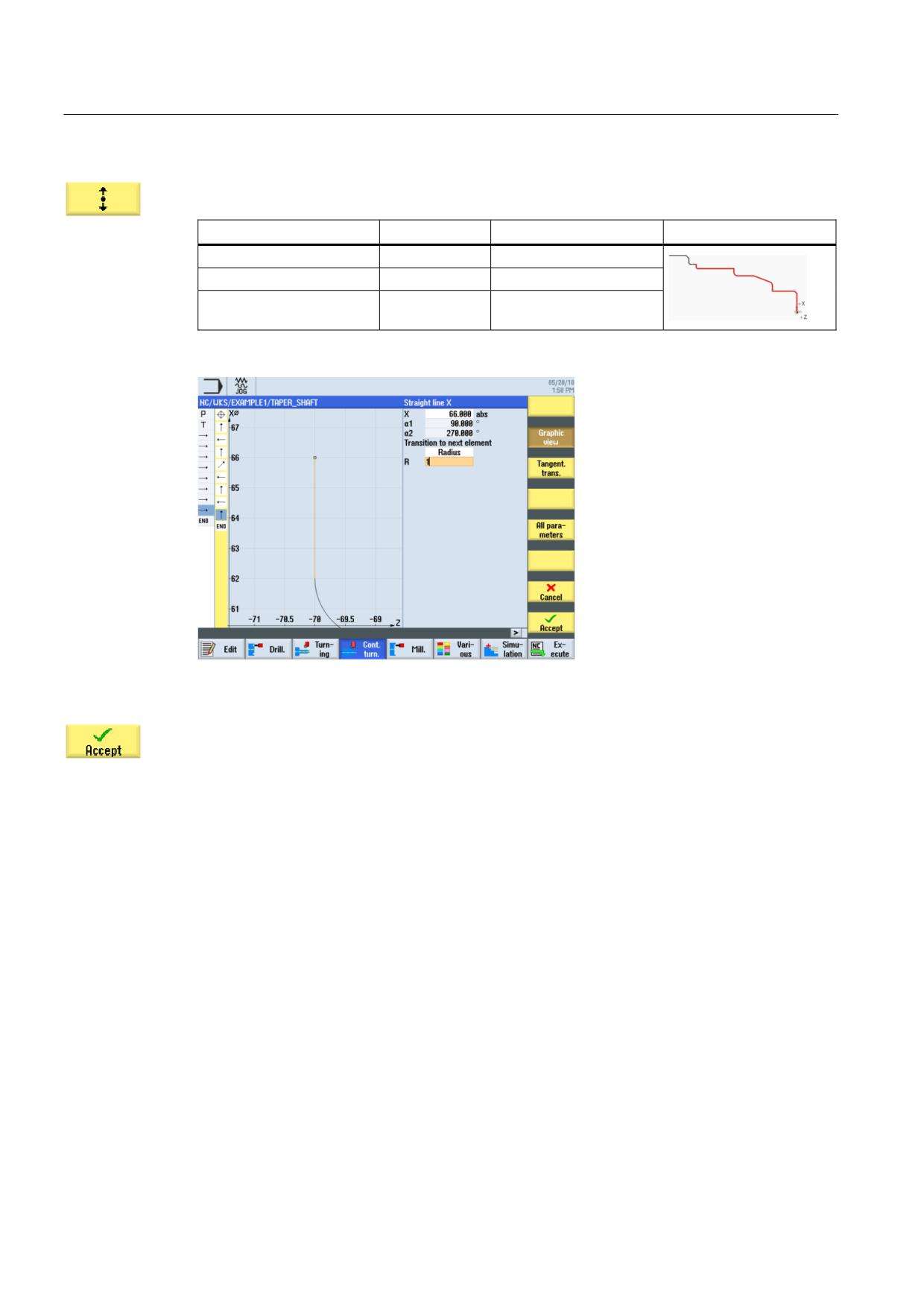
Enter the following value for the vertical straight line in the interactive screenform:
Field
Value
Selection via toggle key
Notes
X
66 abs
X
Transition to next element
Radius
X
R
1
Figure 6-28 Specifying the vertical straight line contour
Accept the entered values.
Turning made easy with ShopTurn
72
Training Documents, 09/2011, 6FC5095-0AB80-1BP1
Example 1: Taper shaft
6.5 Creating contours with the contour calculator and machining sequence
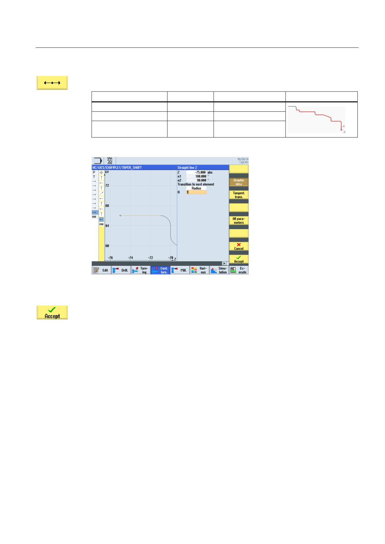
Enter the following values for the horizontal straight line in the interactive screenform:
Field
Value
Selection via toggle key
Notes
Z
-75 abs
X
Transition to next element
Radius
X
R
1
Figure 6-29 Specifying the horizontal straight line contour
Accept the entered values.
Turning made easy with ShopTurn
Training Documents, 09/2011, 6FC5095-0AB80-1BP1
73
Example 1: Taper shaft
6.5 Creating contours with the contour calculator and machining sequence
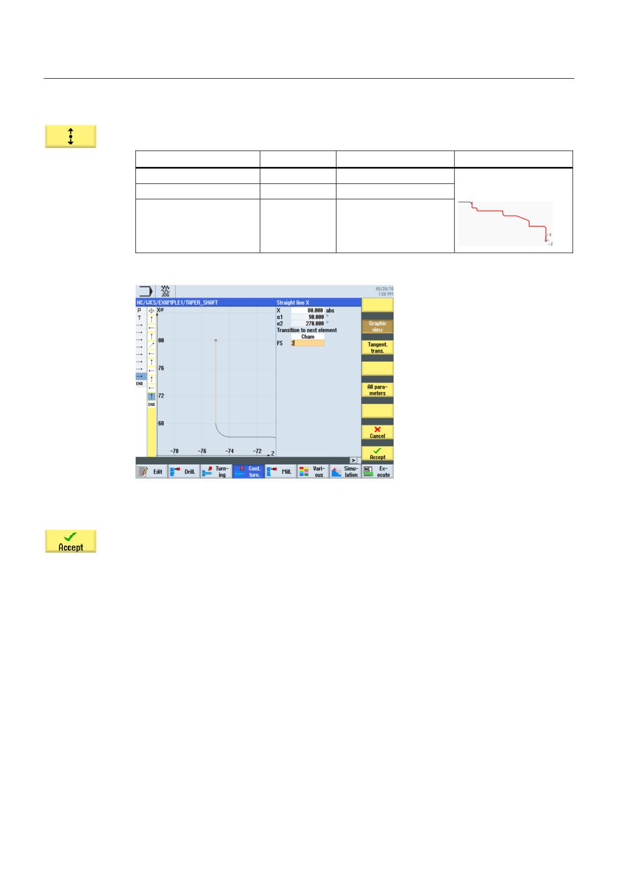
Enter the following value for the vertical straight line in the interactive screenform:
Field
Value
Selection via toggle key
Notes
X
80 abs
X
End point X80 with a
2x45° chamfer
Transition to next element
Chamfer
X
FS
2
Figure 6-30 Specifying the vertical straight line contour
Accept the entered values.
Turning made easy with ShopTurn
74
Training Documents, 09/2011, 6FC5095-0AB80-1BP1
Example 1: Taper shaft
6.5 Creating contours with the contour calculator and machining sequence
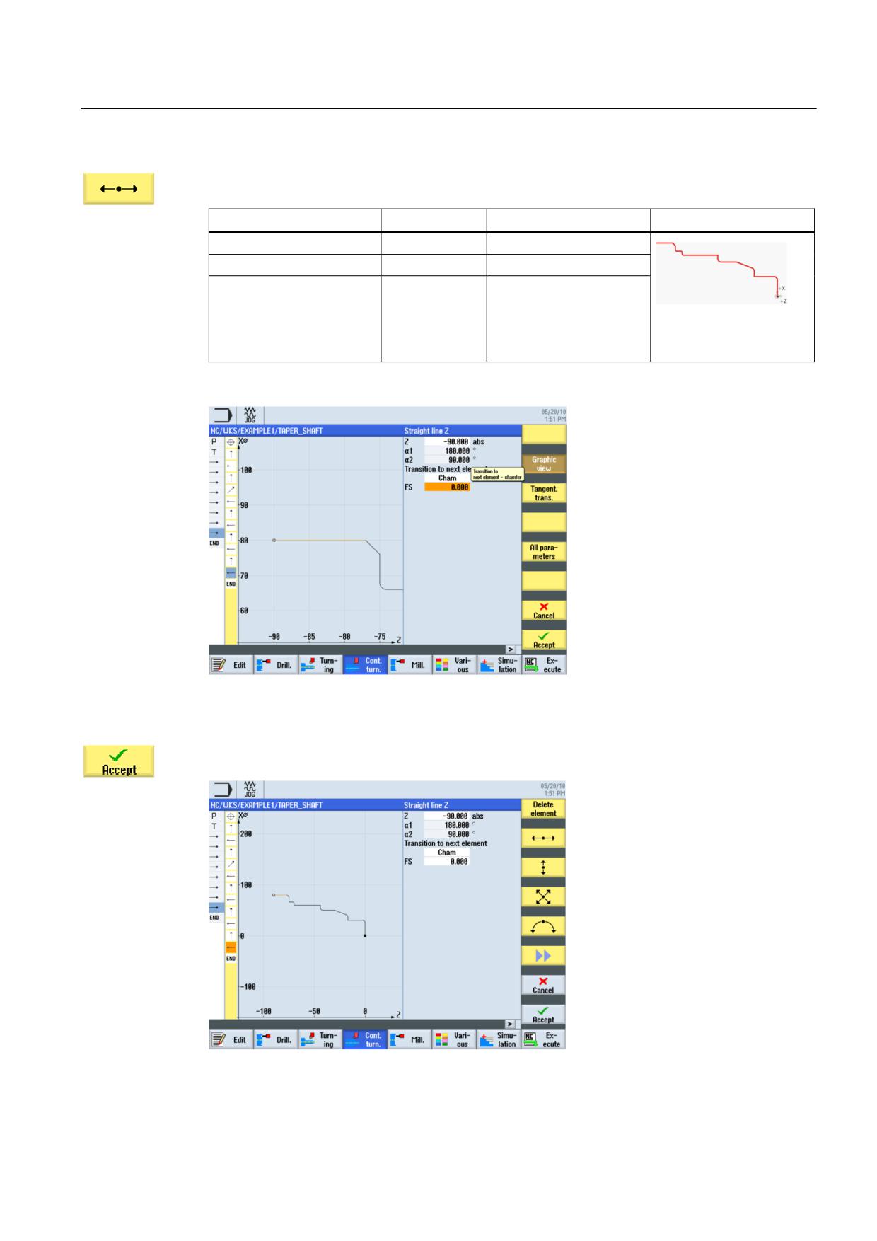
Enter the following values for the horizontal straight line in the interactive screenform:
Field
Value
Selection via toggle key
Notes
Z
-90 abs
X
Transition to next element
Chamfer
X
FS
0
The contour end point lies
at X80 and Z-90 (2mm in
front of the chuck).
Figure 6-31 Specifying the contour end point
Accept the entered values.
Figure 6-32 Full contour
Turning made easy with ShopTurn
Training Documents, 09/2011, 6FC5095-0AB80-1BP1
75
Example 1: Taper shaft
6.5 Creating contours with the contour calculator and machining sequence
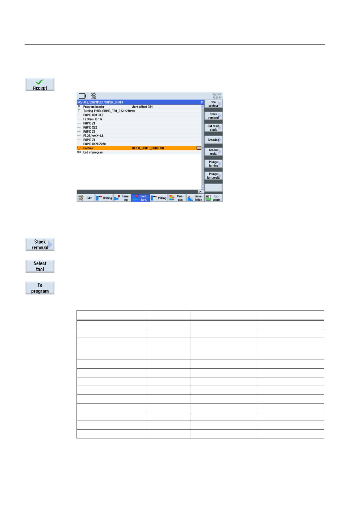
Accept the contour into your process plan.
Figure 6-33 Contour in the process plan
To be able to machine the created contour, you must now create the following work steps.
To this end, proceed as follows:
Select the Stock removal softkey.
Open the tool list and select ROUGHING_T80 A.
Accept the tool into your program.
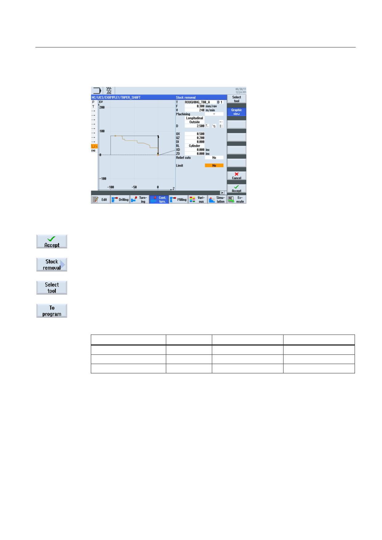
Enter the following values for roughing in the interactive screenform:
Field
Value
Selection via toggle key
Notes
F
0.3
V
240 m/min
X
Machining
longitudinal
X
external
X
roughing
X
D
2.5
UX
0.5
UZ
0.2
DI
0.0
BL
Cylinder
X
XD
0.0 inc
X
ZD
0.0 inc
X
Relief cuts
No
X
Set machining area limits
No
X
Turning made easy with ShopTurn
76
Training Documents, 09/2011, 6FC5095-0AB80-1BP1
Example 1: Taper shaft
6.5 Creating contours with the contour calculator and machining sequence
Figure 6-34 Roughing the contour
Accept the entered values.
Select the Stock removal softkey.
Open the tool list and select FINISHING_T35 A.
Accept the tool into your program.
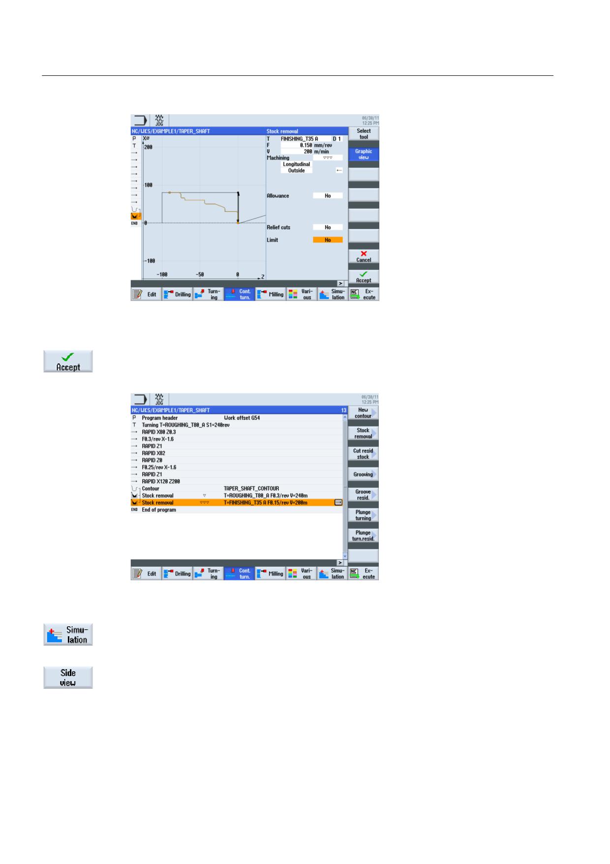
Enter the following values for finishing in the interactive screenform:
Field
Value
Selection via toggle key
Notes
F
0.15
V
200 m/min
X
Machining
Finishing
X
Turning made easy with ShopTurn
Training Documents, 09/2011, 6FC5095-0AB80-1BP1
77
Example 1: Taper shaft
6.5 Creating contours with the contour calculator and machining sequence
Figure 6-35 Finishing the contour
Accept the entered values.
The two machining steps are linked in the work step editor.
Figure 6-36 Linking of the work steps in the process plan
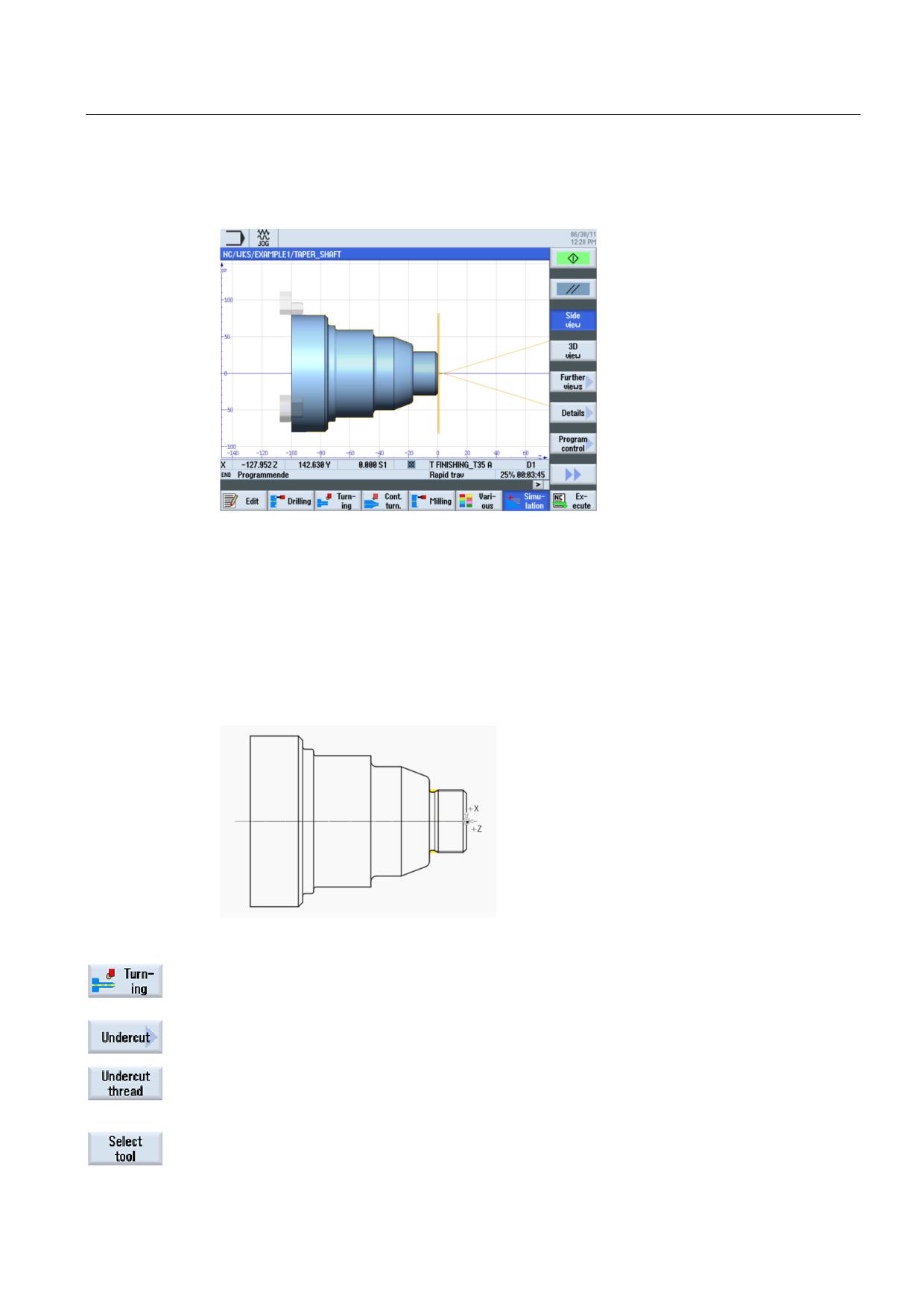
Select the Simulation softkey.
Select the Side view softkey.
Turning made easy with ShopTurn
78
Training Documents, 09/2011, 6FC5095-0AB80-1BP1
Example 1: Taper shaft
6.6 Thread undercut
The following simulation shows the manufacturing sequence for you to check before
manufacturing the workpiece.
Figure 6-37 Simulation - side view
6.6
Thread undercut
Operating sequences
Proceed as follows to create a thread undercut:
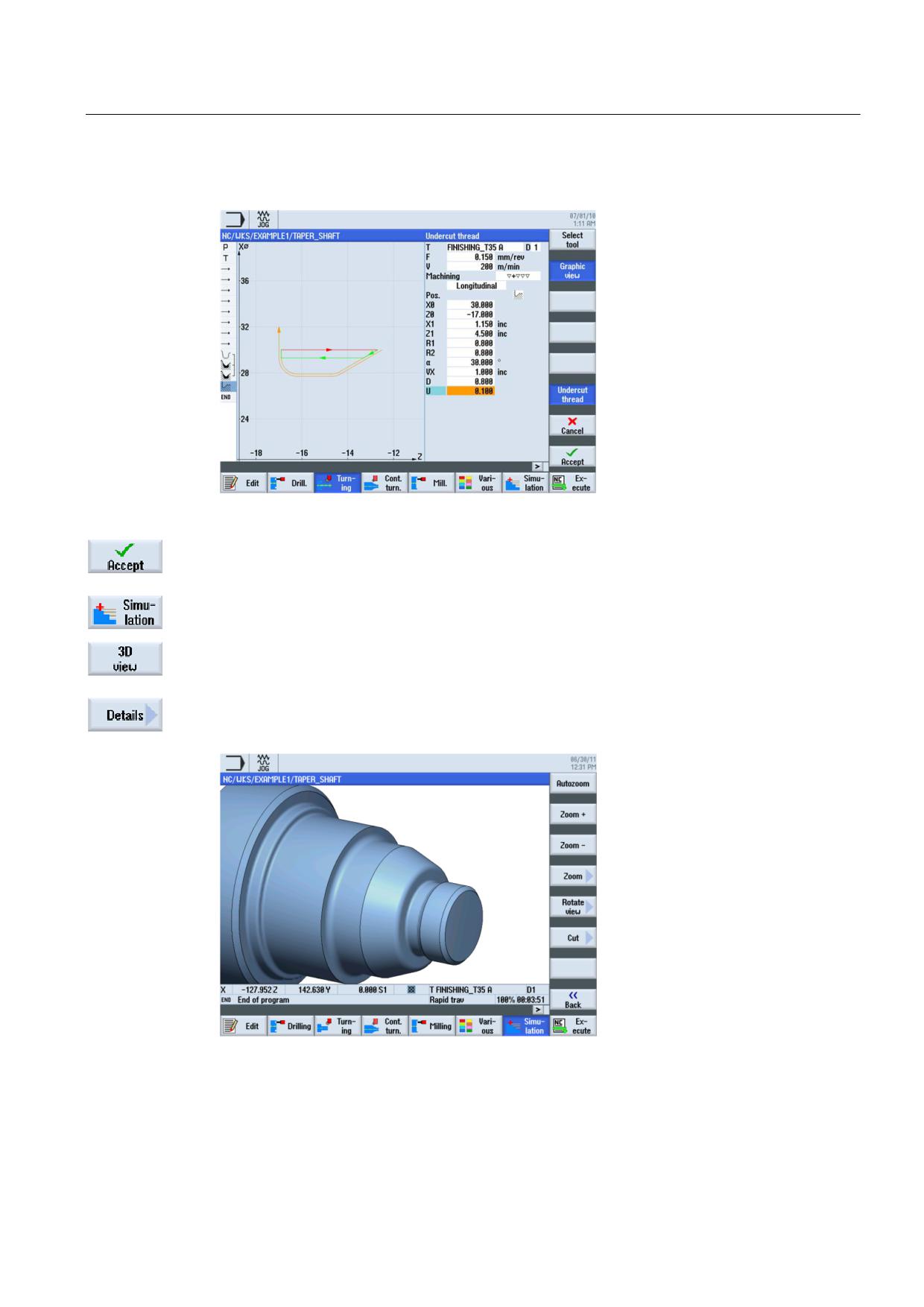
Figure 6-38 Thread undercut
Select the Turning softkey.
Select the Undercut softkey.
Select the Undercut thread softkey.
Open the tool list and select the finishing tool FINISHING_T35 A .
Turning made easy with ShopTurn
Training Documents, 09/2011, 6FC5095-0AB80-1BP1
79
Example 1: Taper shaft
6.6 Thread undercut
Accept the tool into your program.
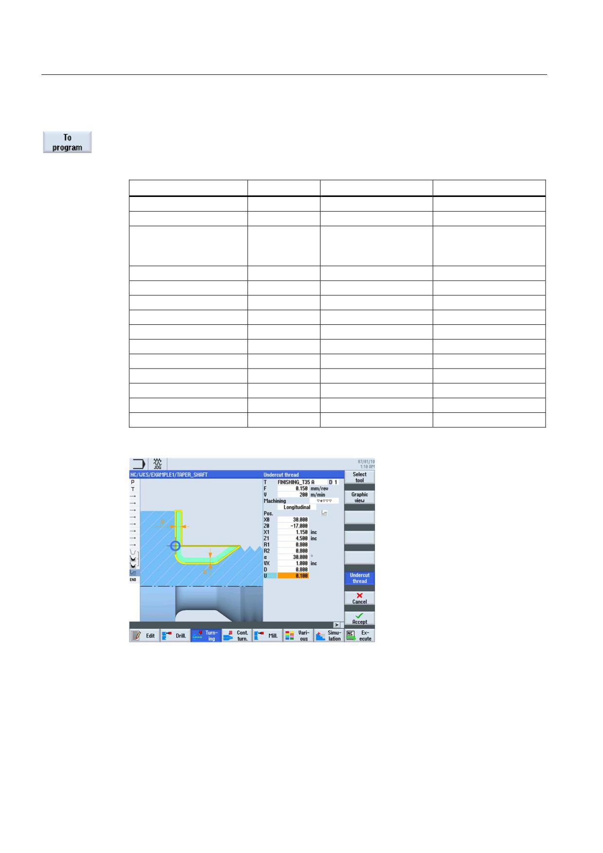
Enter the following values in the interactive screenform:
Field
Value
Selection via toggle key
Notes
F
0.15
V
200 m/min
X
Machining
Roughing/
X
finishing
Longitudinal
X
Position
X
(see illustration above)
X0
30
Z0
-17
X1
1.15 inc
X
Z1
4.5 inc
X
R1
0.8
R2
0.8
α
30
VX
1 inc
X
D
0.8
U
0.1
X (field)
Figure 6-39 Thread undercut
Turning made easy with ShopTurn
80
Training Documents, 09/2011, 6FC5095-0AB80-1BP1
Example 1: Taper shaft
6.6 Thread undercut
Switch between the graphic view and the help display as required.
Figure 6-40 Thread undercut - graphic view
Accept the entered values.
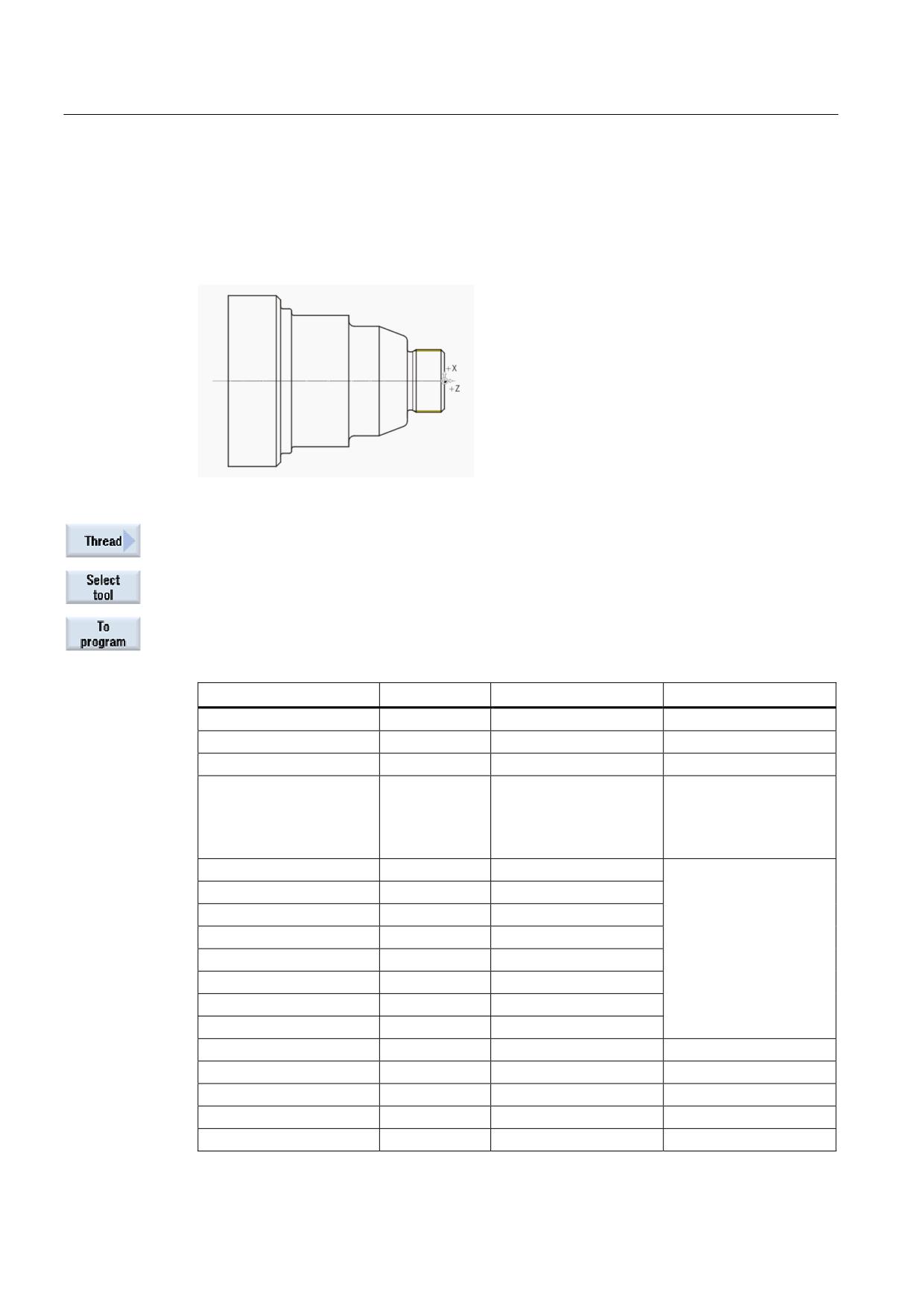
Select the Simulation softkey. Check the thread undercut via the detailed view in the 3D
view, for example.
Select the 3D view softkey.
Select the Details softkey. You can manipulate the display using the Zoom +, Zoom -,
Magnifying glass, etc. softkeys.
Figure 6-41 Detailed view of the simulation in the 3D display
Turning made easy with ShopTurn
Training Documents, 09/2011, 6FC5095-0AB80-1BP1
81
Example 1: Taper shaft
6.7 Thread
6.7
Thread
Operating sequences
Proceed as follows to create a thread:
Figure 6-42 Thread
Select the Thread softkey.
Open the tool list and select THREADING_T1.5.
Accept the tool into your program.
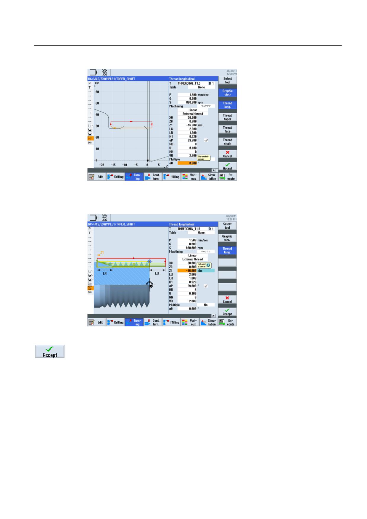
Enter the following values for the thread in the interactive screenform:
Field
Value
Selection via toggle key
Notes
P
1.5 mm/rev
X
G
0
S
800 rpm
X
Machining
Roughing/finishi
X
ng
Linear
X
External thread
X
X0
30
X
The following inputs
define the thread
Z0
0
geometrically.
Z1
-16 abs
X
LW
2
LR
1
H1
0.92
αP
29
X
ND
8
U
0.1
NN
0
VR
2
Multiple threads
No
X
α0
0
Turning made easy with ShopTurn
82
Training Documents, 09/2011, 6FC5095-0AB80-1BP1
Example 1: Taper shaft
6.7 Thread
Figure 6-43 Thread - graphic view
Switch to the help display when necessary.
Figure 6-44 Thread - help display
Accept the entered values.
Turning made easy with ShopTurn
Training Documents, 09/2011, 6FC5095-0AB80-1BP1
83
Example 1: Taper shaft
6.8 Grooves
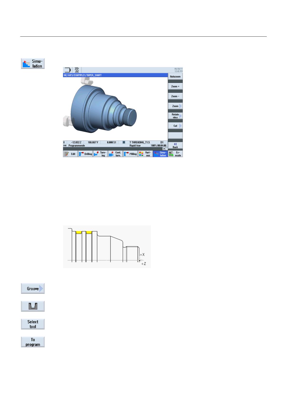
Start the simulation.
Figure 6-45 Thread simulation
6.8
Grooves
Operating sequences
Proceed as follows to create the two grooves:
Figure 6-46 Grooves
Select the Groove softkey.
Select the Groove 2 softkey.
Open the tool list and select the PLUNGE_CUTTER_3 A plunge cutter.
Accept the tool into your program.
Turning made easy with ShopTurn
84
Training Documents, 09/2011, 6FC5095-0AB80-1BP1
Example 1: Taper shaft
6.8 Grooves
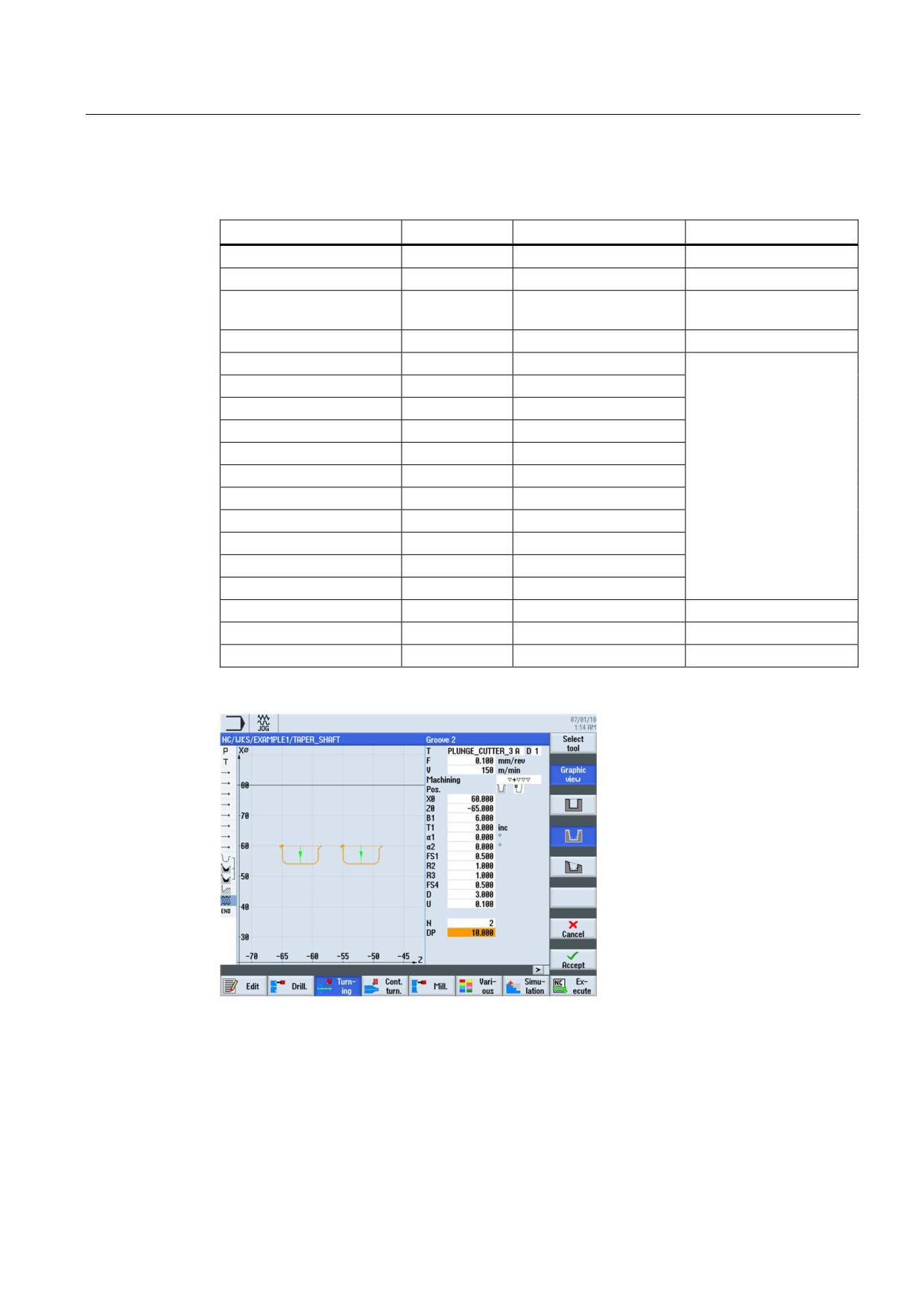
Enter the following values for the grooves in the interactive screenform:
Field
Value
Selection via toggle key
Notes
F
0.1
V
150 m/min
X
Machining
Roughing/finishi
ng
Position
(see illustration above)
X0
60
The following inputs
define the grooves
Z0
-65
geometrically.
B1
6
X (field)
T1
3 inc
X
α1
0
α2
0
FS1
0.5
X (field)
R2
1
X (field)
R3
1
X (field)
FS4
0.5
X (field)
D
3
U
0.1
X (field)
N
2
DP
10
Figure 6-47 Grooves - graphic view
Turning made easy with ShopTurn
Training Documents, 09/2011, 6FC5095-0AB80-1BP1
85
Example 1: Taper shaft
6.8 Grooves
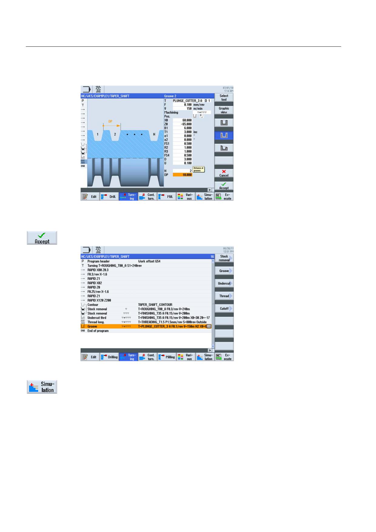
Switch to the help display when necessary.
Figure 6-48 Grooves - help display
Accept the entered values.
Figure 6-49 Process plan with grooves
Start the simulation in the side view or in the 2-window view, for example.
Turning made easy with ShopTurn
86
Training Documents, 09/2011, 6FC5095-0AB80-1BP1
Example 1: Taper shaft
6.8 Grooves
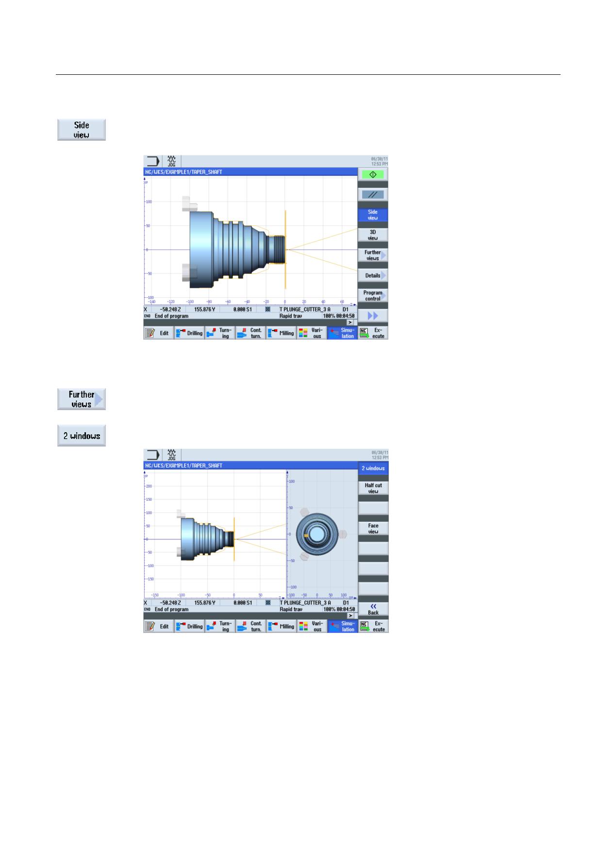
Select the Side view softkey.
Figure 6-50 Simulation - side view
Select the Further views softkey.
Select the 2-window softkey.
Figure 6-51 Simulation - 2-window view
Turning made easy with ShopTurn
Training Documents, 09/2011, 6FC5095-0AB80-1BP1
87
Example 1: Taper shaft
6.8 Grooves
Turning made easy with ShopTurn
88
Training Documents, 09/2011, 6FC5095-0AB80-1BP1
Example 2: Input shaft
7
7.1
Overview
Learning objectives
In this section you will learn the following new functions. You will learn how to...
● perform face turning;
● work with the contour calculator (advanced application);
● machine residual material.
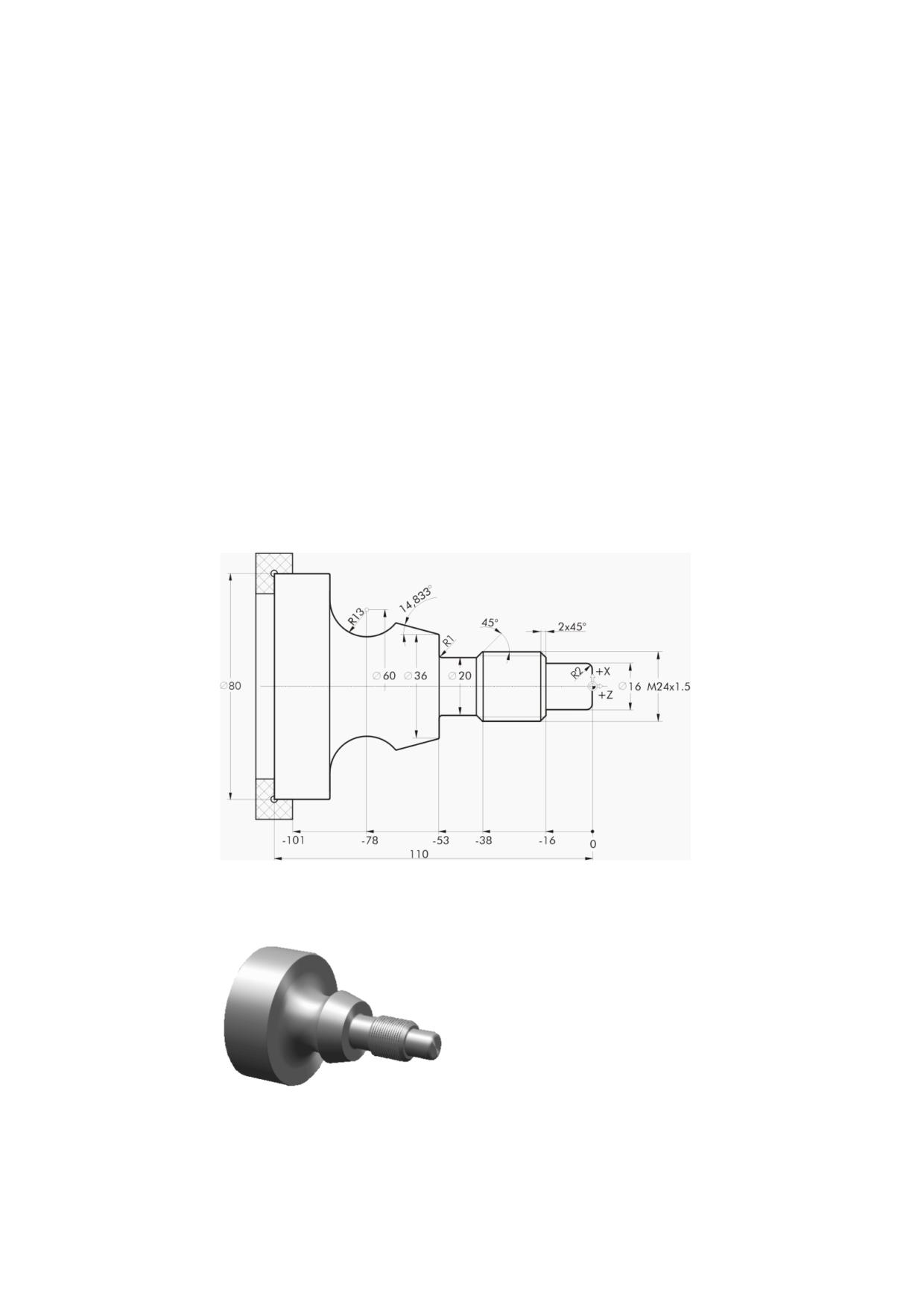
Task
Figure 7-1
Workshop drawing - Example 2:
Figure 7-2
Workpiece - Example 2:
Turning made easy with ShopTurn
Training Documents, 09/2011, 6FC5095-0AB80-1BP1
89
Example 2: Input shaft
7.2 Face turning
Preparation
Perform the following steps without help:
1. Create a new workpiece with the name 'EXAMPLE2'.
2. Create a new step sequence program with the name 'DRIVE_SHAFT' .
3. Specify the blank dimensions (for the procedure, see example 1).
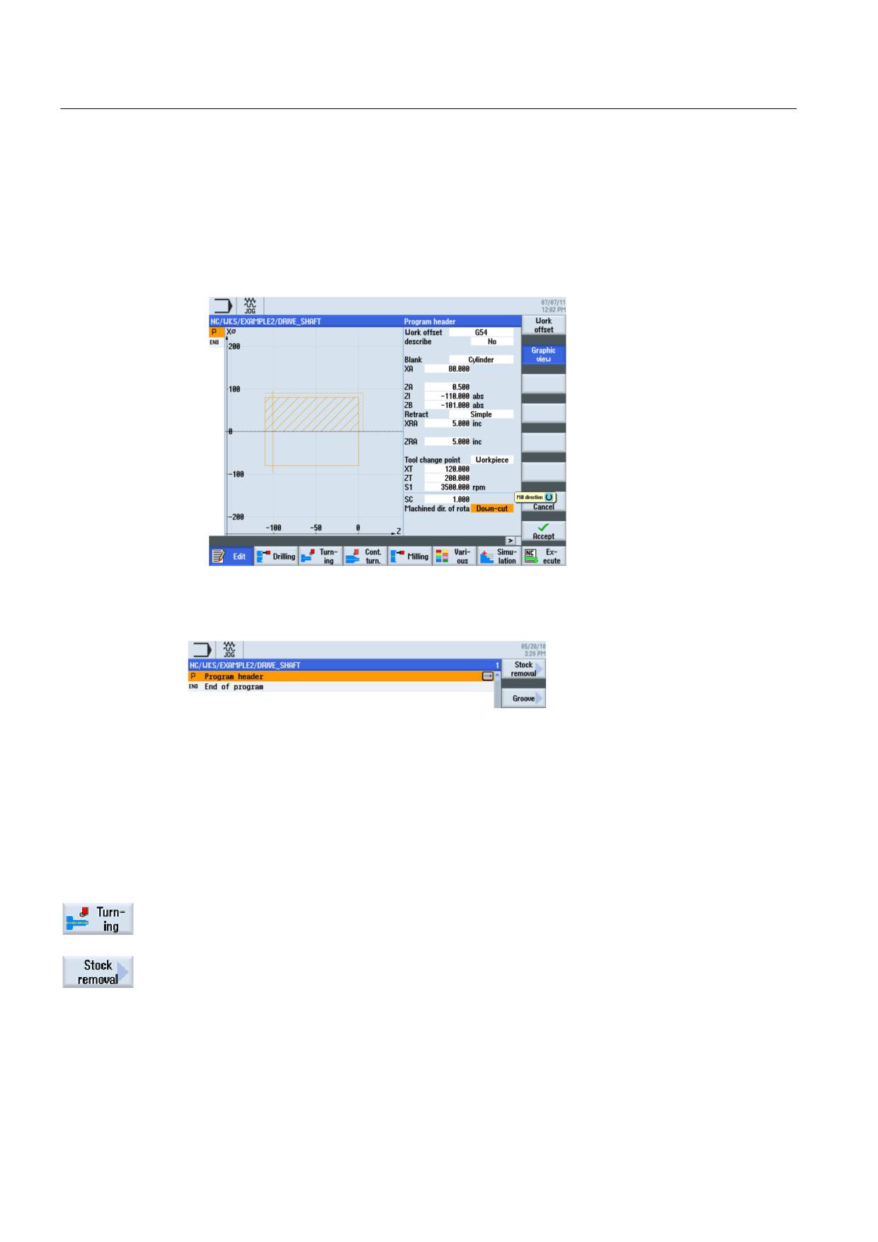
Figure 7-3
Creating a program header
Following creation of the program header, the process plan looks like this.
Figure 7-4
Work step program
7.2
Face turning
Operating sequences
Proceed as follows to face turn the workpiece:
Select the Turning softkey.
Select the Stock removal softkey.
Turning made easy with ShopTurn
90
Training Documents, 09/2011, 6FC5095-0AB80-1BP1
Example 2: Input shaft
7.3 Creating the contour, stock removal and residual stock removal
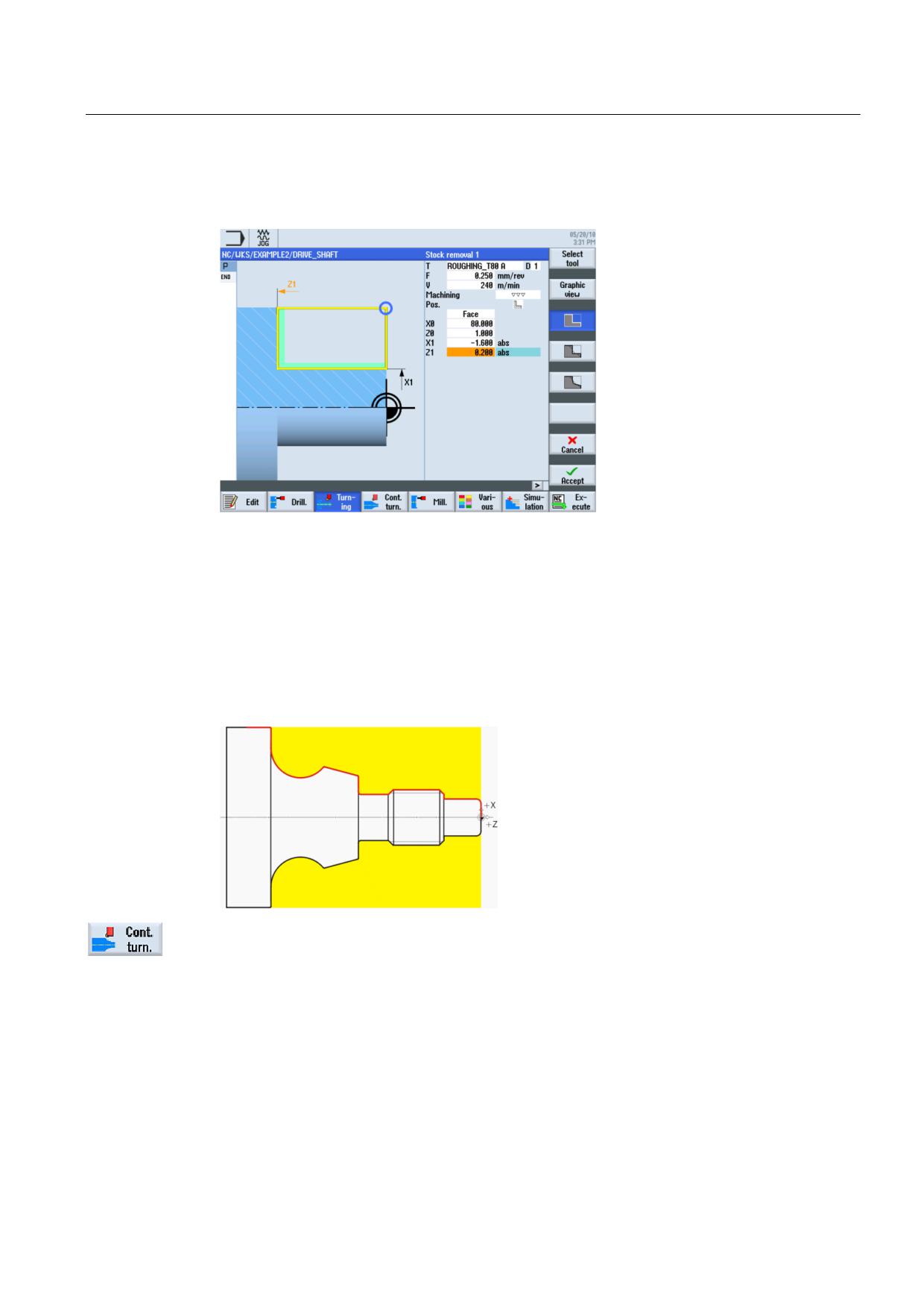
Since face turning should be completed in one cut, switch to finishing during machining.
Select the ROUGHING_T80 A tool and enter the following values.
Figure 7-5
Face turning the workpiece
7.3
Creating the contour, stock removal and residual stock removal
Operating sequences
Proceed as follows to enter the contour:
Select the Contour turning softkey.
Turning made easy with ShopTurn
Training Documents, 09/2011, 6FC5095-0AB80-1BP1
91
Example 2: Input shaft
7.3 Creating the contour, stock removal and residual stock removal
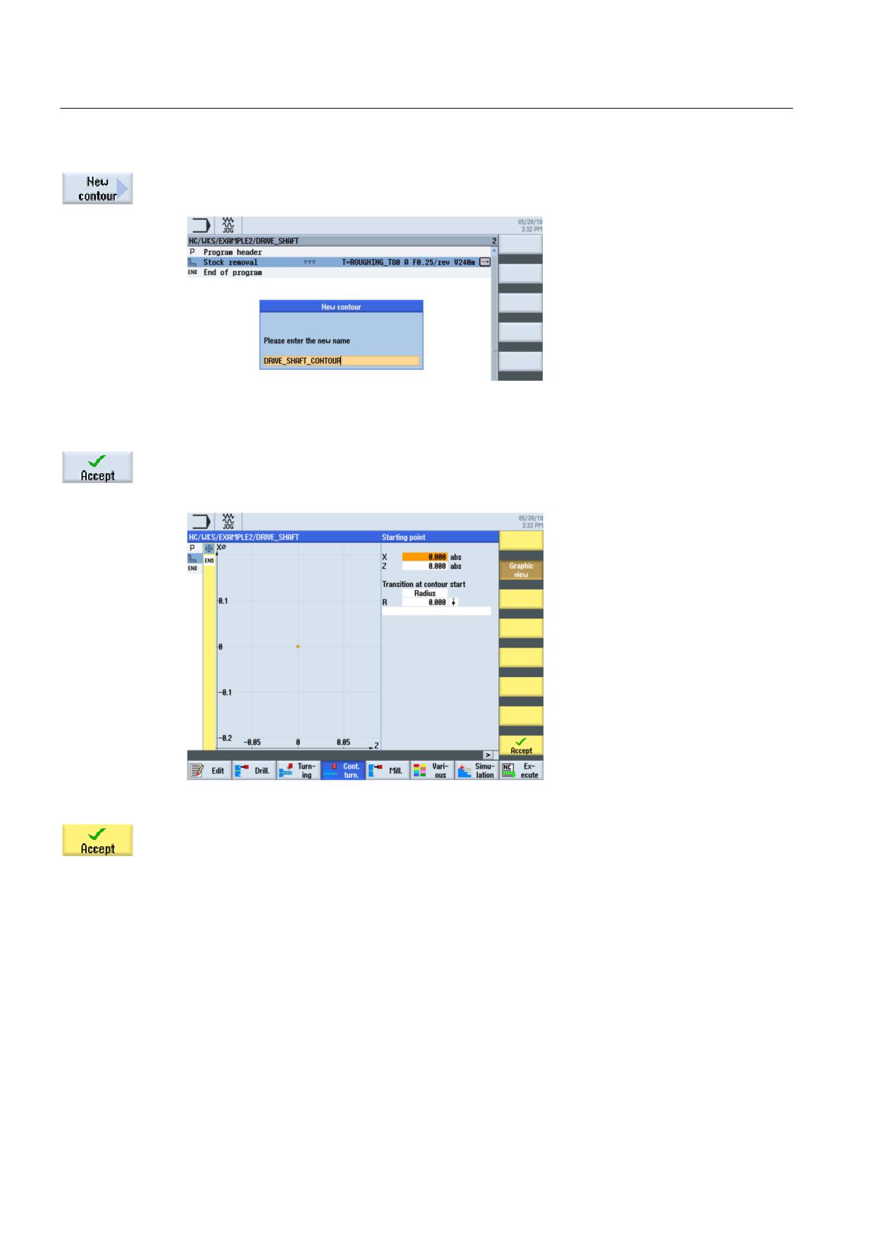
Select the New contour softkey. Enter the name 'DRIVE_SHAFT_CONTOUR' for the
contour.
Figure 7-6
Creating the contour
Confirm your input.
You can accept starting point X0/Z0 directly (see illustration below).
Figure 7-7
Accepting the starting point
Confirm your input.
Turning made easy with ShopTurn
92
Training Documents, 09/2011, 6FC5095-0AB80-1BP1
Example 2: Input shaft
7.3 Creating the contour, stock removal and residual stock removal
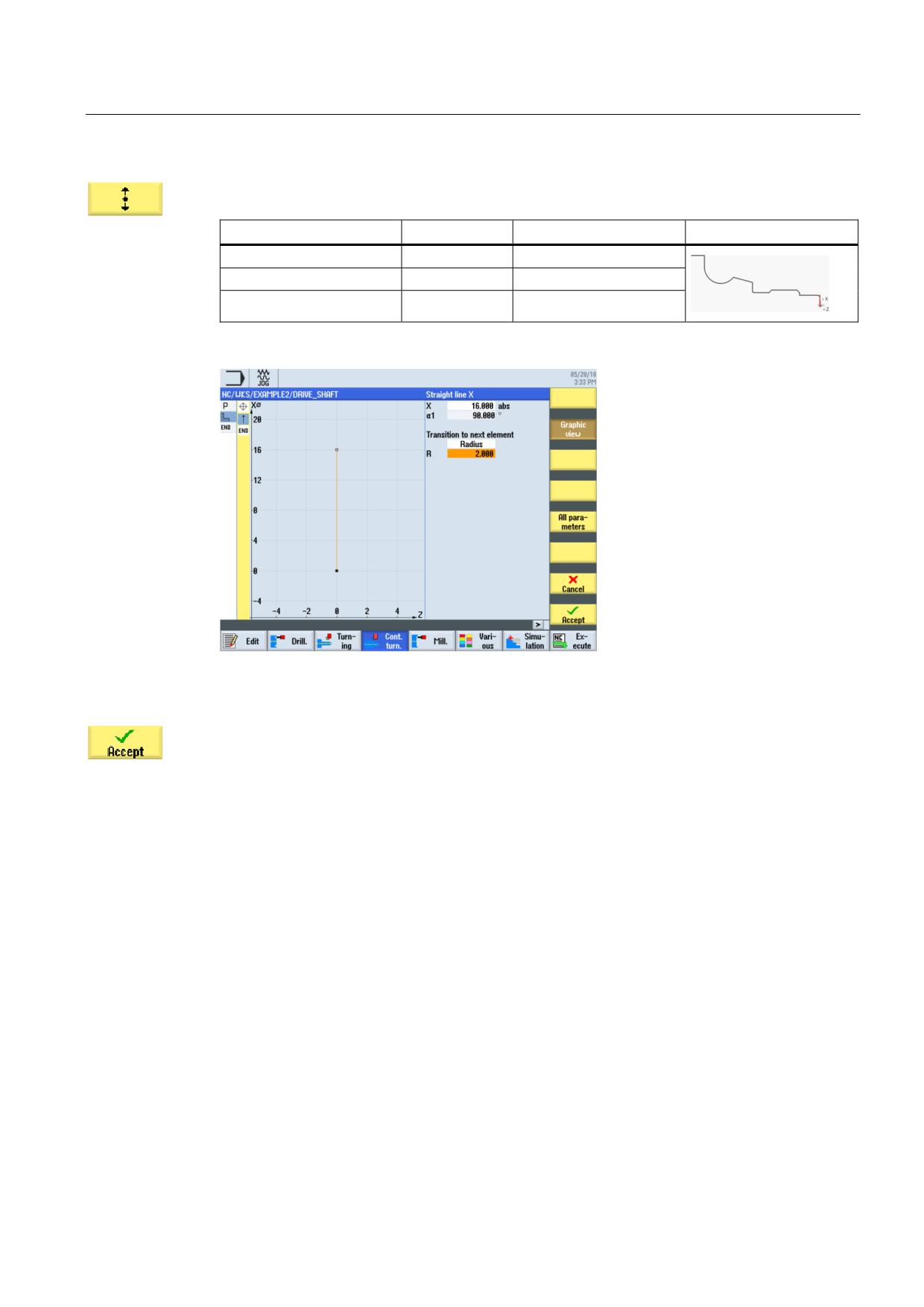
Enter the following values for the vertical straight line in the interactive screenform:
Field
Value
Selection via toggle key
Notes
X
16 abs
X
Transition to next element
Radius
X
R
2
Figure 7-8
Specifying the vertical straight line contour
Accept the entered values.
Turning made easy with ShopTurn
Training Documents, 09/2011, 6FC5095-0AB80-1BP1
93
Example 2: Input shaft
7.3 Creating the contour, stock removal and residual stock removal
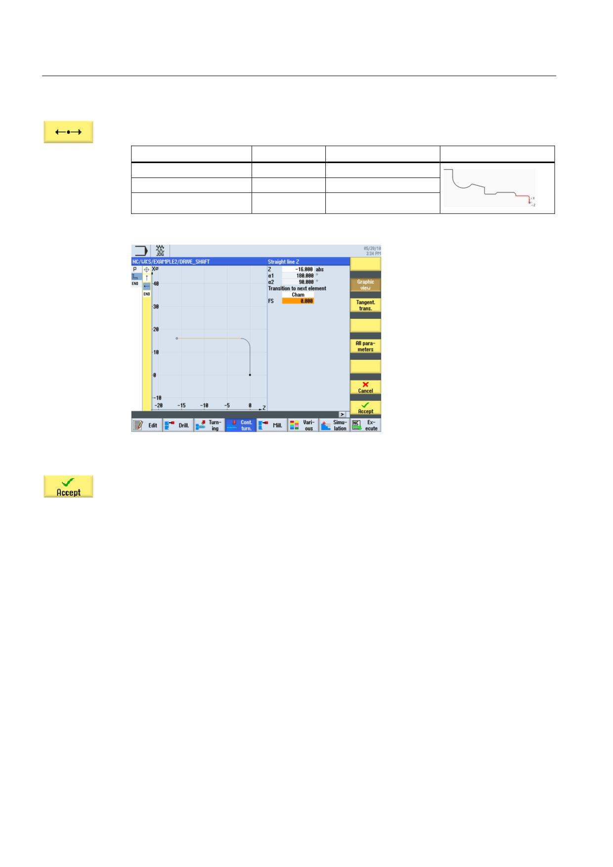
Enter the following values for the horizontal straight line in the interactive screenform:
Field
Value
Selection via toggle key
Notes
Z
-16 abs
X
Transition to next element
Chamfer
X
FS
0
Figure 7-9
Specifying the horizontal straight line contour
Accept the entered values.
Turning made easy with ShopTurn
94
Training Documents, 09/2011, 6FC5095-0AB80-1BP1
Example 2: Input shaft
7.3 Creating the contour, stock removal and residual stock removal
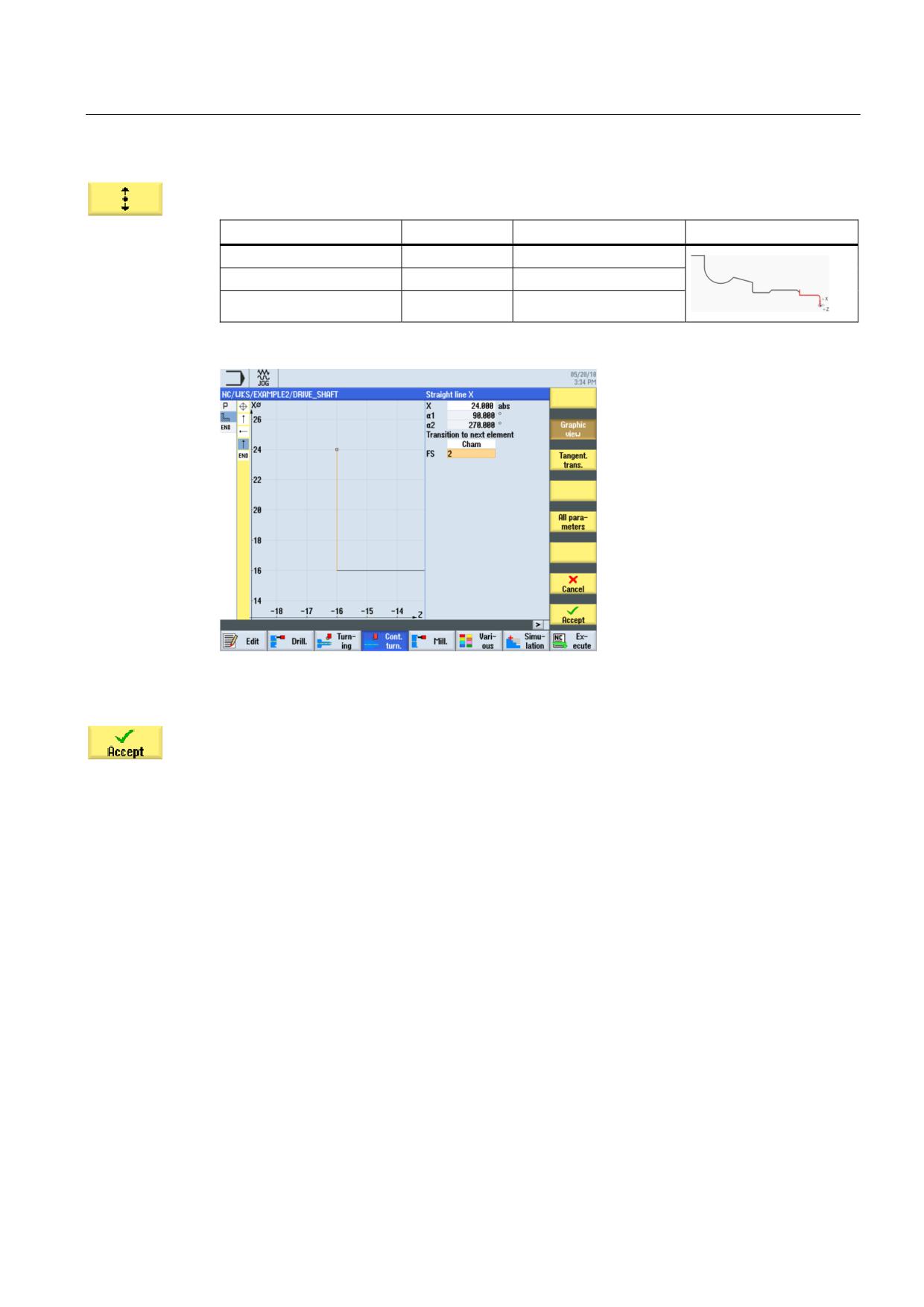
Enter the following value for the vertical straight line in the interactive screenform:
Field
Value
Selection via toggle key
Notes
X
24 abs
X
Transition to next element
Chamfer
X
FS
2
Figure 7-10 Specifying the vertical straight line contour
Accept the entered values.
Turning made easy with ShopTurn
Training Documents, 09/2011, 6FC5095-0AB80-1BP1
95
Example 2: Input shaft
7.3 Creating the contour, stock removal and residual stock removal
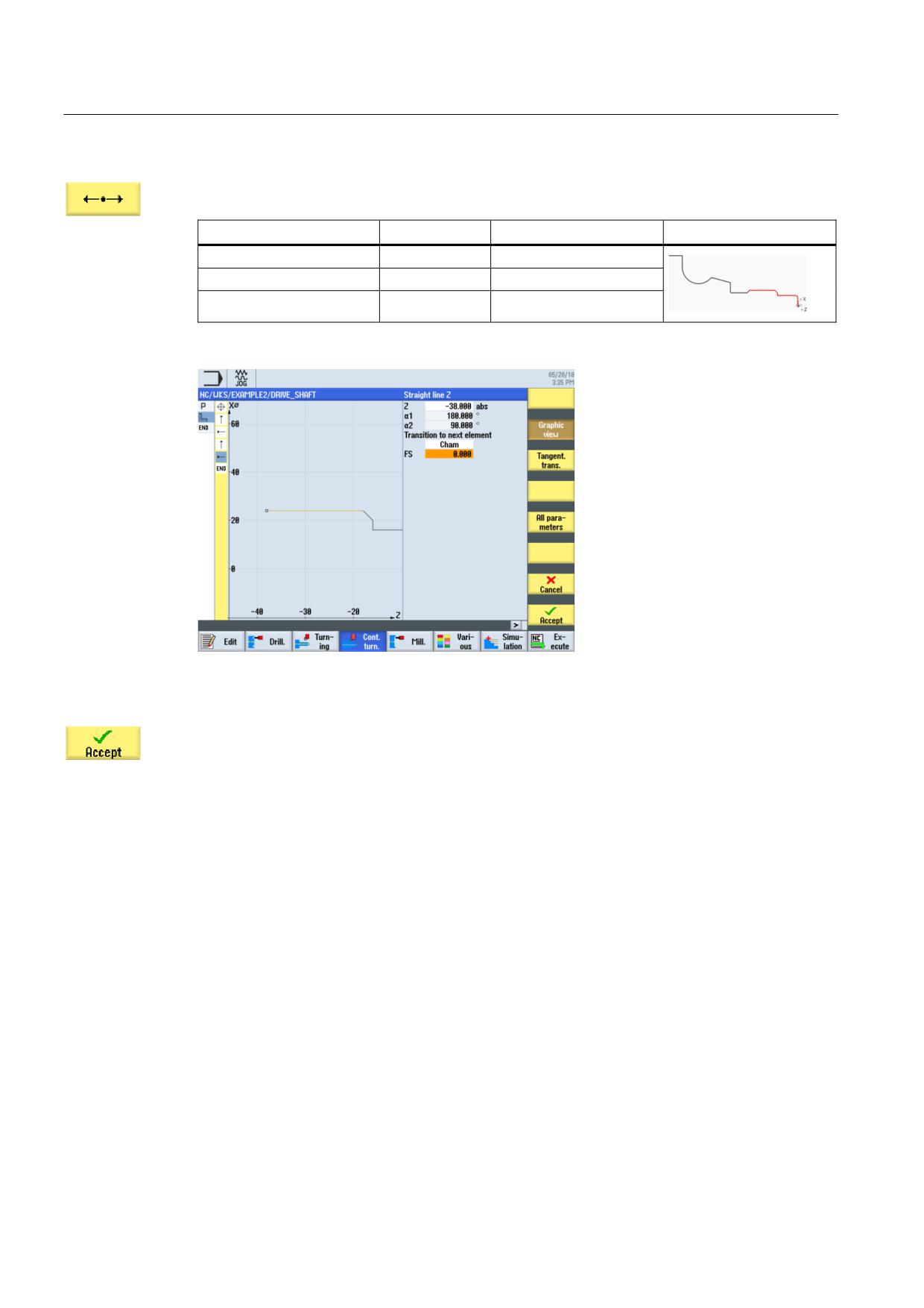
Enter the following values for the horizontal straight line in the interactive screenform:
Field
Value
Selection via toggle key
Notes
Z
-38 abs
X
Transition to next element
Chamfer
X
FS
0
Figure 7-11 Specifying the horizontal straight line contour
Accept the entered values.
Turning made easy with ShopTurn
96
Training Documents, 09/2011, 6FC5095-0AB80-1BP1
Example 2: Input shaft
7.3 Creating the contour, stock removal and residual stock removal
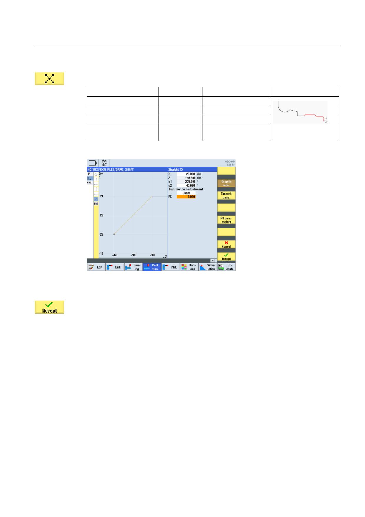
Enter the following values for the sloping straight line in the interactive screenform:
Field
Value
Selection via toggle key
Notes
X
20 abs
X
α2
45
X
Transition to next element
Chamfer
X
FS
0
The entered angle refers
to the preceding element.
Figure 7-12 Specifying the sloping straight line contour
Accept the entered values.
Turning made easy with ShopTurn
Training Documents, 09/2011, 6FC5095-0AB80-1BP1
97
Example 2: Input shaft
7.3 Creating the contour, stock removal and residual stock removal
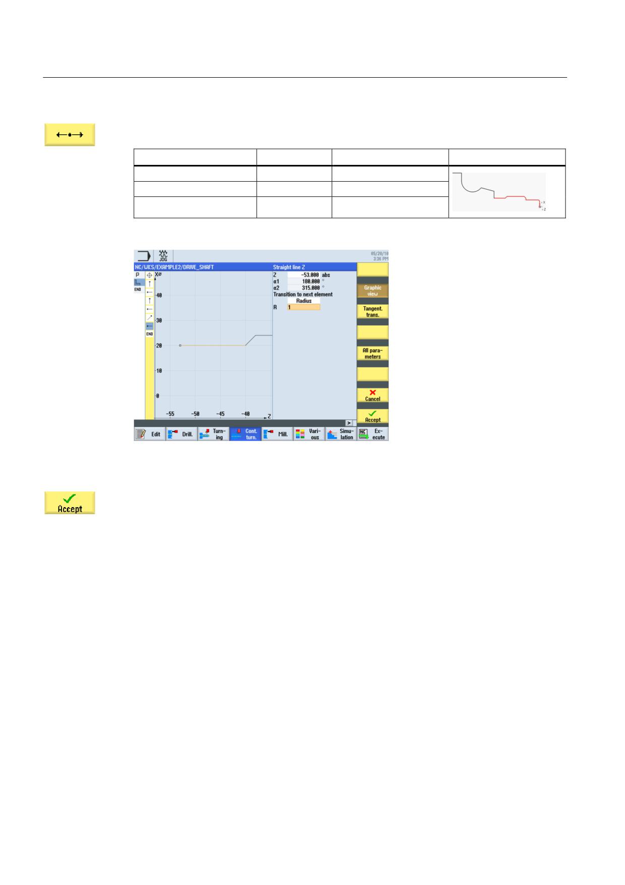
Enter the following values for the horizontal straight line in the interactive screenform:
Field
Value
Selection via toggle key
Notes
Z
-53 abs
X
Transition to next element
Radius
X
R
1
Figure 7-13 Specifying the horizontal straight line contour
Accept the entered values.
Turning made easy with ShopTurn
98
Training Documents, 09/2011, 6FC5095-0AB80-1BP1
Example 2: Input shaft
7.3 Creating the contour, stock removal and residual stock removal
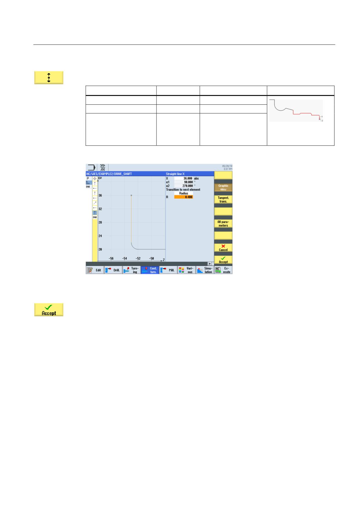
Enter the following values for the vertical straight line in the interactive screenform:
Field
Value
Selection via toggle key
Notes
X
36 abs
X
Transition to next element
Radius
X
R
0.4
Round the transition to
the next element with
R0.4.
Figure 7-14 Specifying the vertical straight line contour
Accept the entered values.
Turning made easy with ShopTurn
Training Documents, 09/2011, 6FC5095-0AB80-1BP1
99
Example 2: Input shaft
7.3 Creating the contour, stock removal and residual stock removal
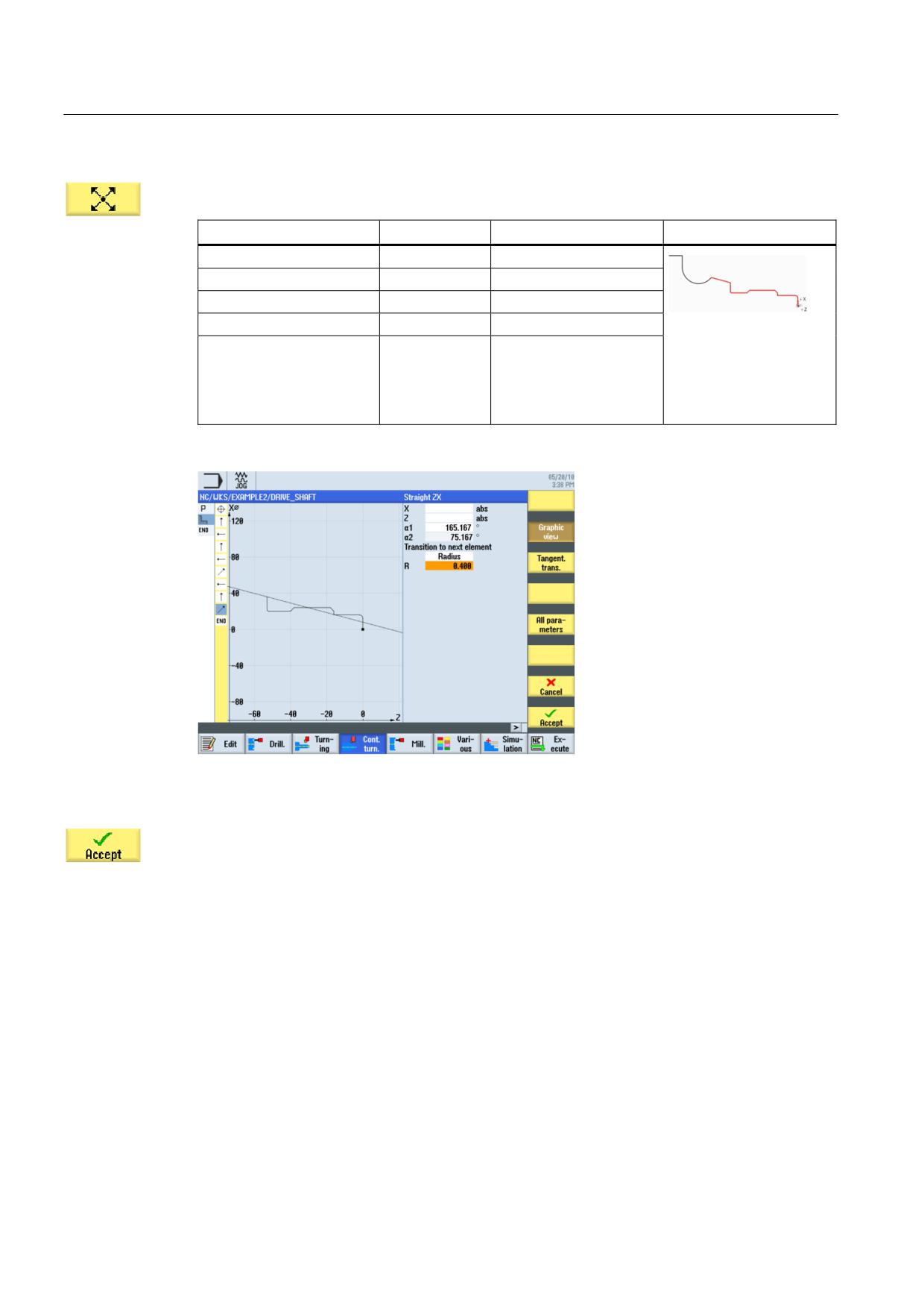
Enter the following values for the next section in the interactive screenform:
Field
Value
Selection via toggle key
Notes
X
X
Z
X
α1
165.167°
Transition to next element
Radius
X
Nothing more is known of
R
0.4
the path than the angle to
the Z axis, 165.167°. In
such cases, simply
continue the construction
with the next element.
Figure 7-15 Specifying the inclined straight line contour
Accept the entered values.
Turning made easy with ShopTurn
100
Training Documents, 09/2011, 6FC5095-0AB80-1BP1
Example 2: Input shaft
7.3 Creating the contour, stock removal and residual stock removal
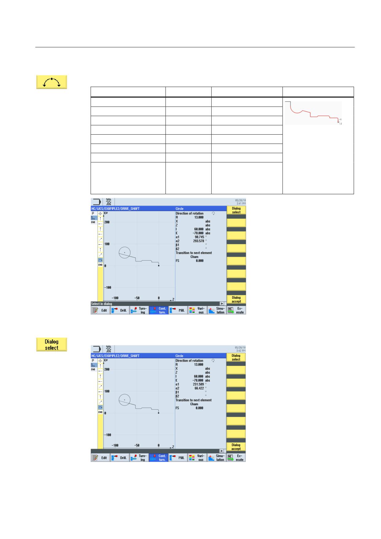
Enter the following values for the next section in the interactive screenform:
Field
Value
Selection via toggle key
Notes
Direction of rotation
Right
X
R
13
X
Z
The missing points of the
I
60 abs
X
previous contour element
are calculated using the
K
-78 abs
X
known dimensions of the
Transition to next element
Chamfer
X
arc.
R
0
Since there are several
possibilities, it is
important that the correct
selection is made.
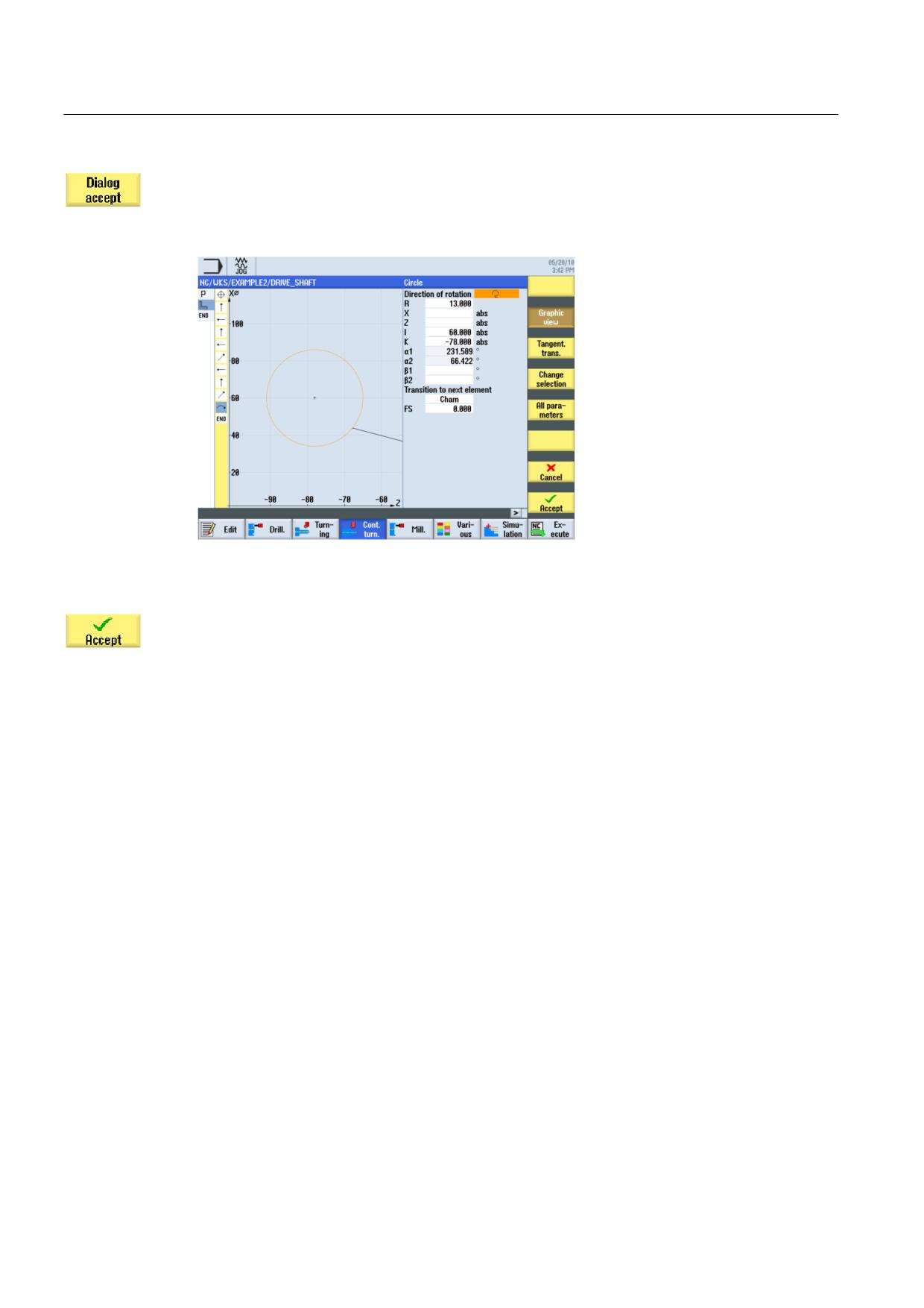
Figure 7-16 Specifying the arc contour
Select the recommended solution in accordance with the below illustration.
Figure 7-17 Confirming the contour selection
Turning made easy with ShopTurn
Training Documents, 09/2011, 6FC5095-0AB80-1BP1
101
Example 2: Input shaft
7.3 Creating the contour, stock removal and residual stock removal
Select the desired construction, then accept.
Since the end point of the arc is not known, simply continue with the construction. You could
also use the All parameters softkey to enter the exit angle here.
Figure 7-18 Accepting the arc contour
Accept the contour section.
Turning made easy with ShopTurn
102
Training Documents, 09/2011, 6FC5095-0AB80-1BP1
Example 2: Input shaft
7.3 Creating the contour, stock removal and residual stock removal
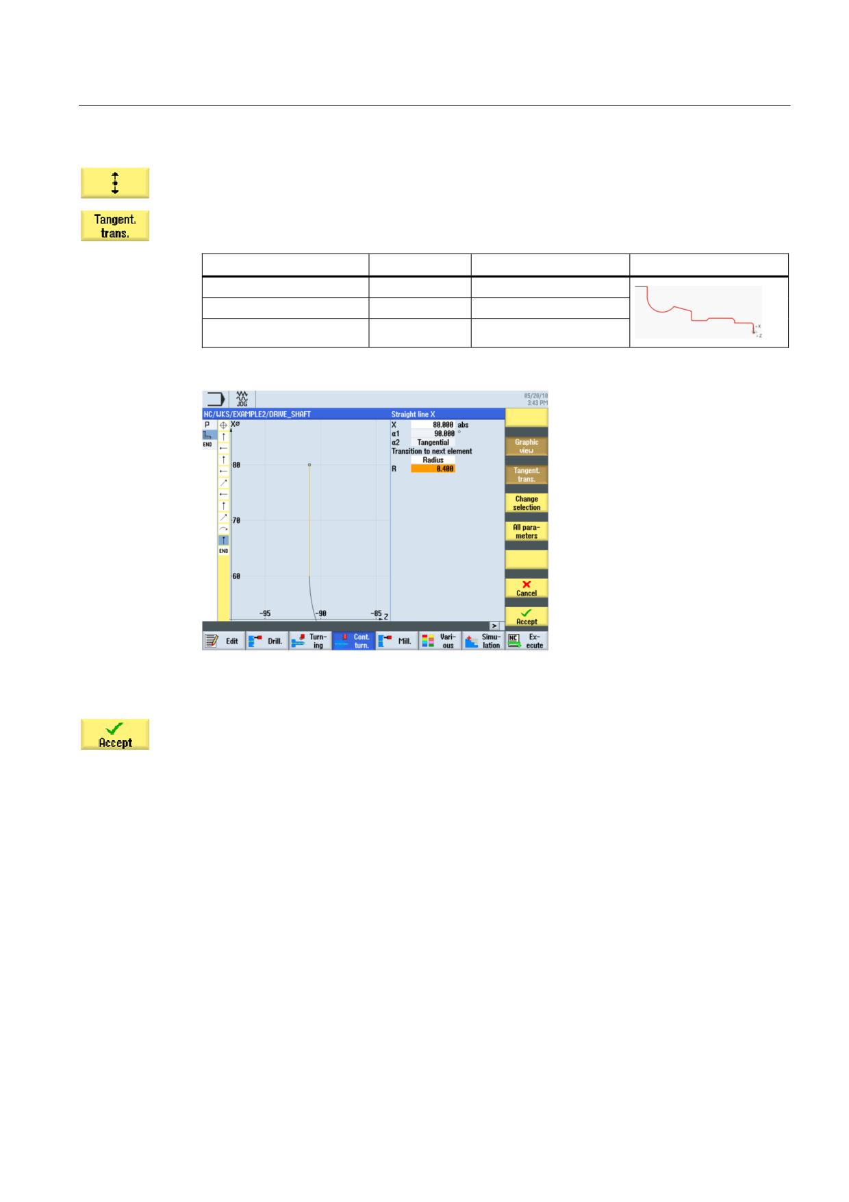
A tangential path follows.
Select the Tangent to prec.elem. softkey.
Field
Value
Selection via toggle key
Notes
X
80 abs
X
Transition to next element
Radius
X
R
0.4
Figure 7-19 Specifying the vertical straight line contour
Accept the entered values.
Turning made easy with ShopTurn
Training Documents, 09/2011, 6FC5095-0AB80-1BP1
103
Example 2: Input shaft
7.3 Creating the contour, stock removal and residual stock removal
Enter the following values for the horizontal straight line in the interactive screenform:
Field
Value
Selection via toggle key
Notes
Z
-100 abs
X
Transition to next element
Chamfer
X
FS
0
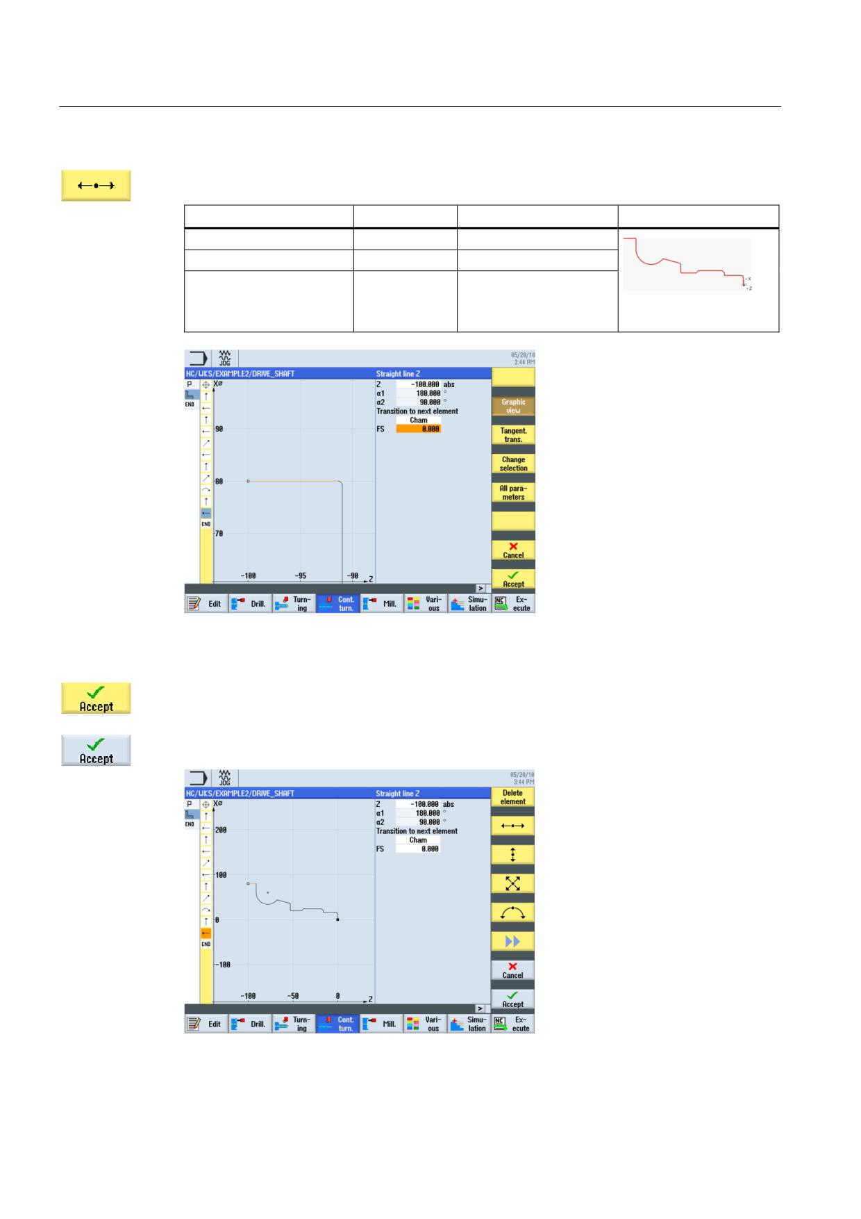
The end point of the
contour is at Z-100.
Figure 7-20 Specifying the horizontal straight line contour
Accept the entered values.
Accept the contour into your process plan.
Figure 7-21 Accepting the contour
Turning made easy with ShopTurn
104
Training Documents, 09/2011, 6FC5095-0AB80-1BP1
Example 2: Input shaft
7.3 Creating the contour, stock removal and residual stock removal
Stock removal, residual stock removal and finishing
To be able to machine the created contour, you must now create the following work steps.
To this end, proceed as follows:
Select the Stock removal softkey.
Open the tool list and select the ROUGHING_T80 A tool.
Accept the tool into your program.
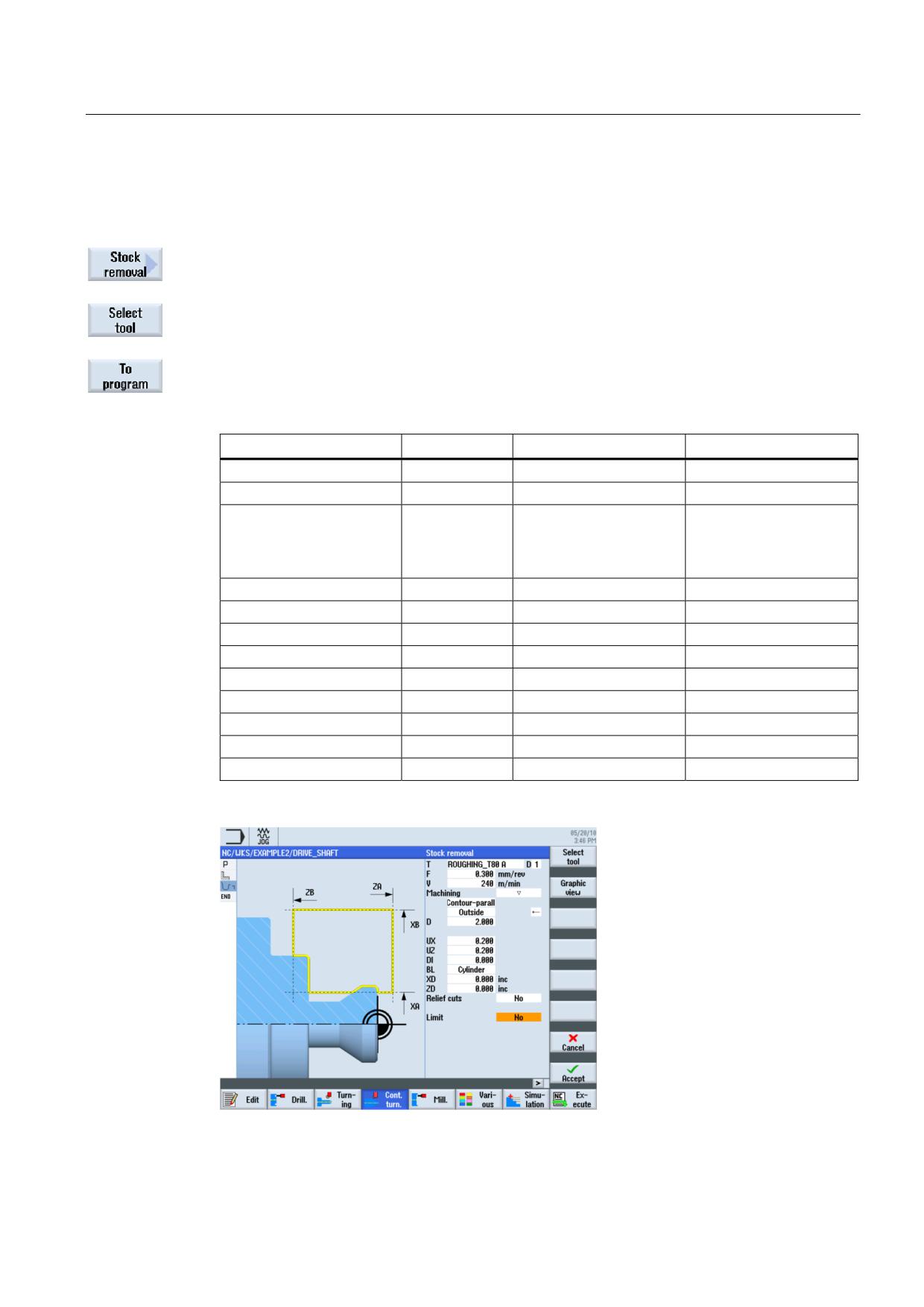
Enter the following values for roughing in the interactive screenform:
Field
Value
Selection via toggle key
Notes
F
0.3
S
240 rpm
X
Machining
contour-parallel
X
The machining of the
external
X
contour, for example, is
roughing
X
performed parallel to the
contour here.
D
2.0
UX
0.2
UZ
0.2
DI
0.0
BL
Cylinder
X
XD
0.0 inc
X
ZD
0.0 inc
X
Relief cuts
No
X
Set machining area limits
No
X
Figure 7-22 Roughing the contour
Turning made easy with ShopTurn
Training Documents, 09/2011, 6FC5095-0AB80-1BP1
105
Example 2: Input shaft
7.3 Creating the contour, stock removal and residual stock removal
Accept the entered values.
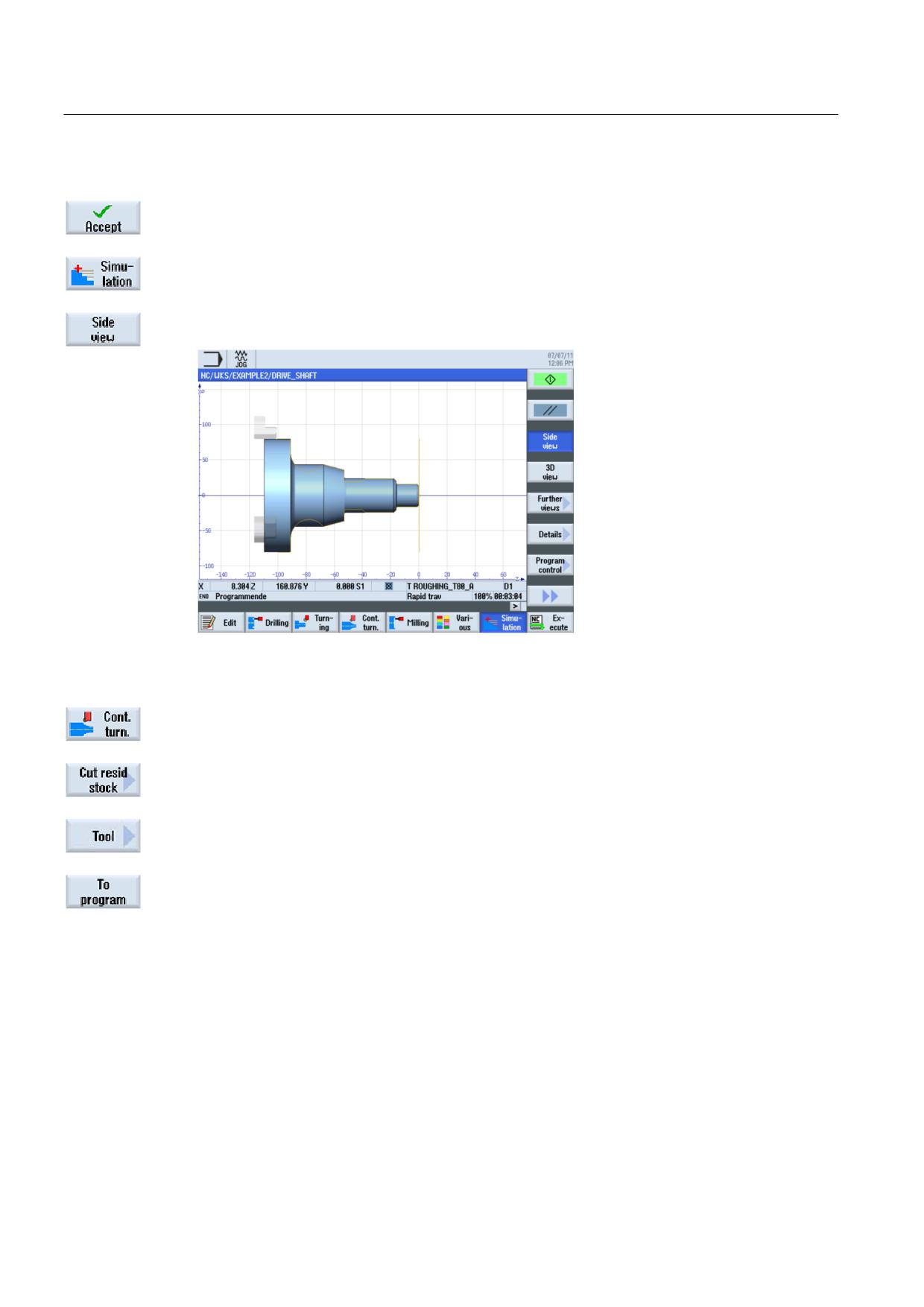
Select the Simulation softkey.
Select the Side view softkey.
Figure 7-23 Roughing the contour - side view simulation
Select the Contour turning softkey.
Select the Residual stock removal softkey.
Open the tool list and select the FINISHING_T35 A tool.
Accept the tool into your program.
Turning made easy with ShopTurn
106
Training Documents, 09/2011, 6FC5095-0AB80-1BP1
Example 2: Input shaft
7.3 Creating the contour, stock removal and residual stock removal
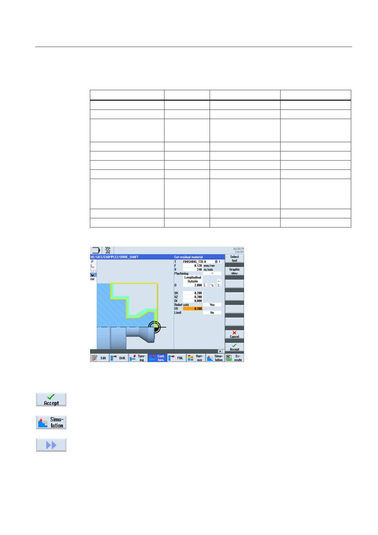
Enter the following values for residual stock removal in the interactive screenform:
Field
Value
Selection via toggle key
Notes
F
0.12
V
240 m/min
X
Machining
longitudinal
X
external
X
roughing
X
D
2.0
UX
0.2
UZ
0.2
DI
0.0
Relief cuts
Yes
X
To be able to cut all
residual material, you
must switch the input field
to Yes .
FR
0.2
Set machining area limits
No
X
Figure 7-24 Cutting contour residual material
Accept the entered values.
Select the Simulation softkey.
Extend the menu.
Turning made easy with ShopTurn
Training Documents, 09/2011, 6FC5095-0AB80-1BP1
107
Example 2: Input shaft
7.3 Creating the contour, stock removal and residual stock removal
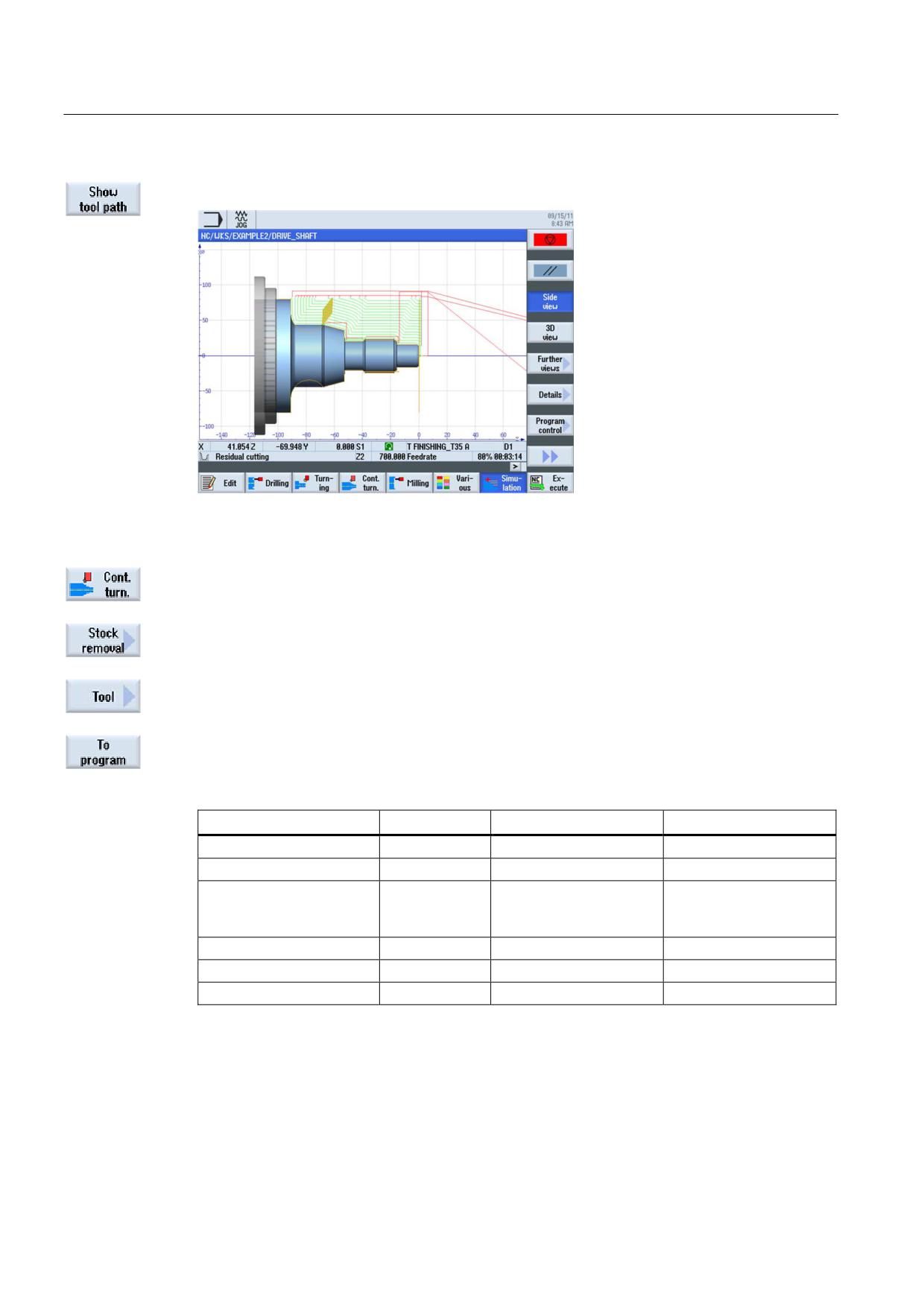
Activate the display of traversing paths.
Figure 7-25 Cutting residual material - side view simulation
Select the Contour turning softkey.
Select the Stock removal softkey.
Open the tool list and select the FINISHING_T35 A tool.
Accept the tool into your program.
Enter the following values for finishing in the interactive screenform:
Field
Value
Selection via toggle key
Notes
F
0.12
S
280 rpm
X
Machining
longitudinal
X
external
X
finishing
X
Allowance
No
X
Relief cuts
Yes
X
Set machining area limits
No
X
Turning made easy with ShopTurn
108
Training Documents, 09/2011, 6FC5095-0AB80-1BP1
Example 2: Input shaft
7.3 Creating the contour, stock removal and residual stock removal
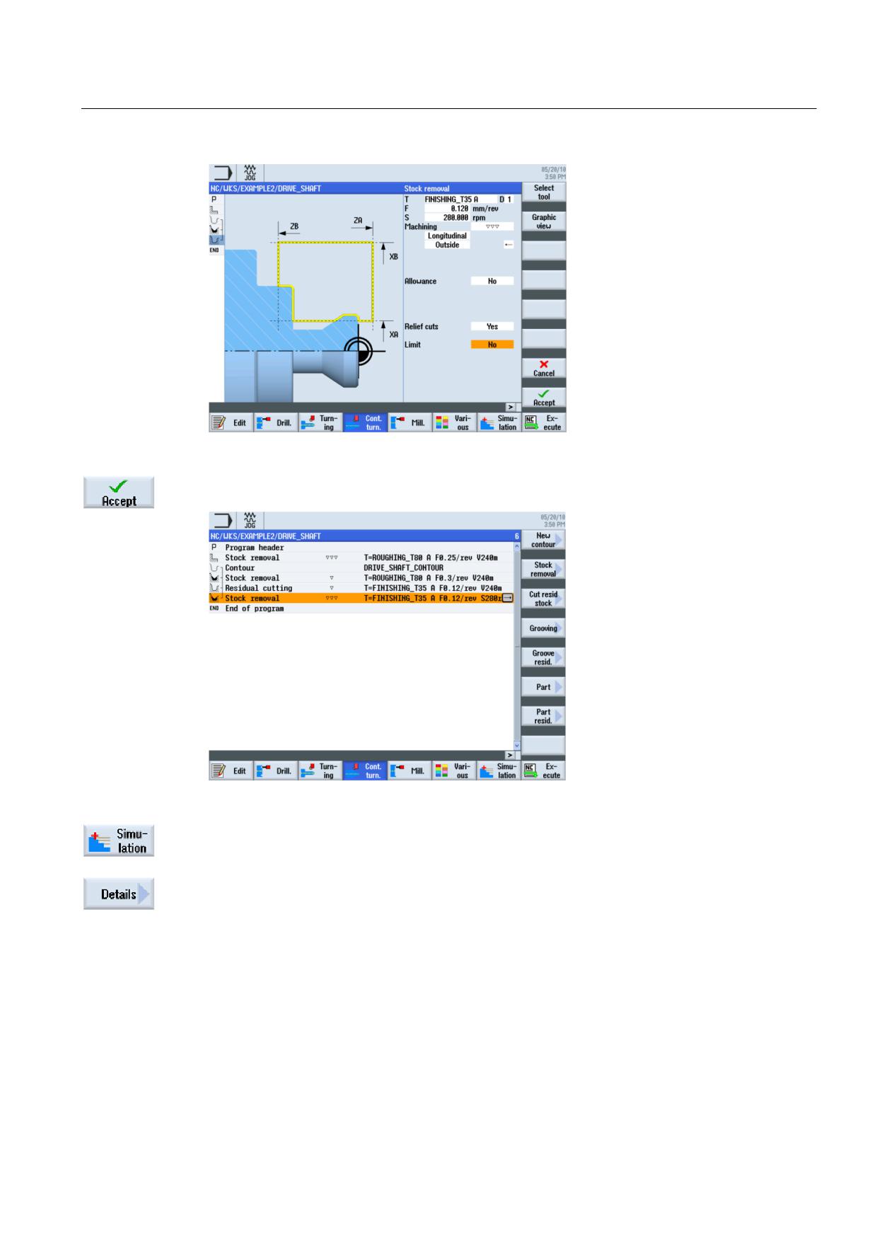
Figure 7-26 Finishing the contour
Accept the entered values. After acceptance, the process plan looks like this.
Figure 7-27 Process plan
Start the simulation.
Select the Details softkey. Here you can expand or minimize the view.
Turning made easy with ShopTurn
Training Documents, 09/2011, 6FC5095-0AB80-1BP1
109
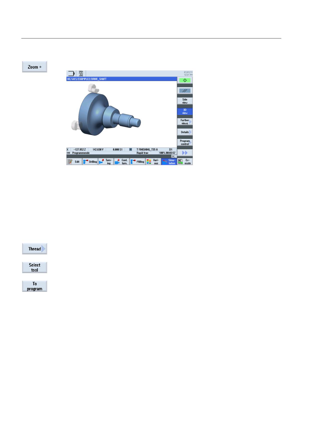
Example 2: Input shaft
7.4 Thread
The Zoom + softkey expands the view.
Figure 7-28 3D view simulation - details
7.4
Thread
Operating sequences
Proceed as follows to create a thread.
Select the Thread softkey.
Open the tool list and select THREADING_T1.5.
Accept the tool into your program.
Turning made easy with ShopTurn
110
Training Documents, 09/2011, 6FC5095-0AB80-1BP1
Example 2: Input shaft
7.4 Thread
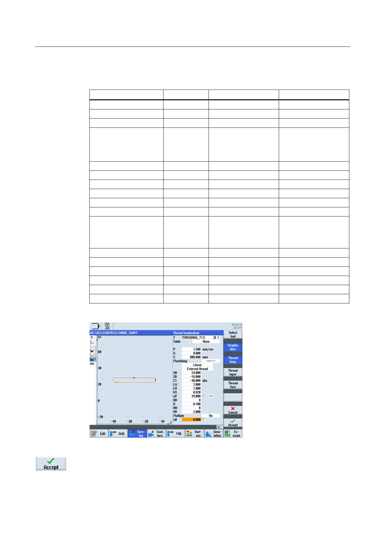
Enter the following values for the thread in the interactive screenform:
Field
Value
Selection via toggle key
Notes
P
1.5 mm/rev
X
G
0
S
800 rpm
X
Machining
Roughing +
X
finishing
Linear
X
External thread
X
X0
24
Z0
-16
Z1
-40 abs
X
LW
2
LR
1
H1
0.92
αP
29
X
Infeed with
X
alternating
flanks
ND
8
U
0.1
NN
0
VR
2
Multiple threads
No
X
α0
0
Figure 7-29 Producing a thread
Accept the entered values.
Turning made easy with ShopTurn
Training Documents, 09/2011, 6FC5095-0AB80-1BP1
111
Example 2: Input shaft
7.4 Thread
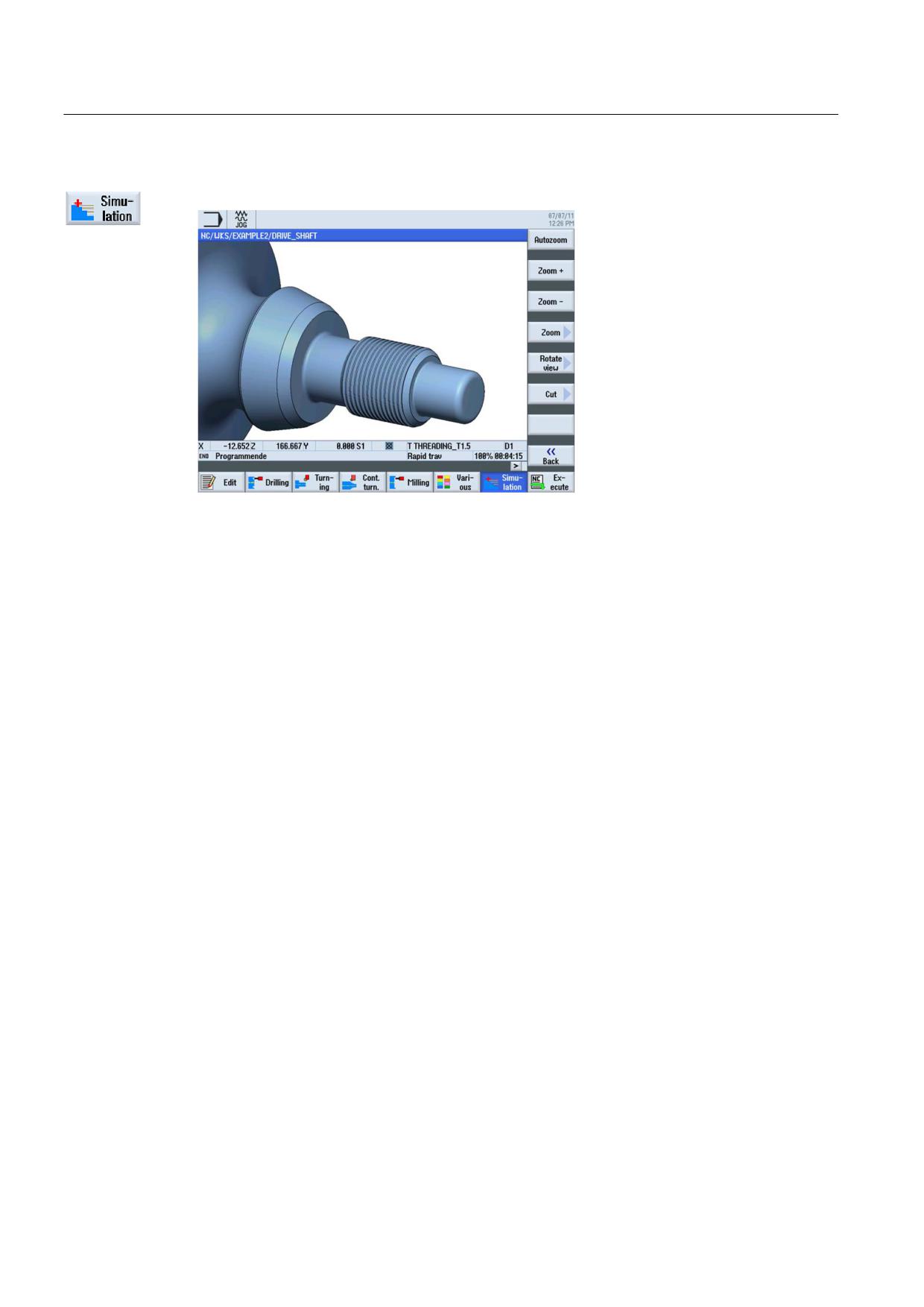
Figure 7-30 3D view simulation - details
Turning made easy with ShopTurn
112
Training Documents, 09/2011, 6FC5095-0AB80-1BP1
Example 3: Guide shaft
8
8.1
Overview
Learning objectives
In this section you will learn the following new functions. You will learn how to...
● create any blank;
● perform stock removal of the difference material between the blank and the machined
part;
● drill on the front face;
● mill on the front face;
Task
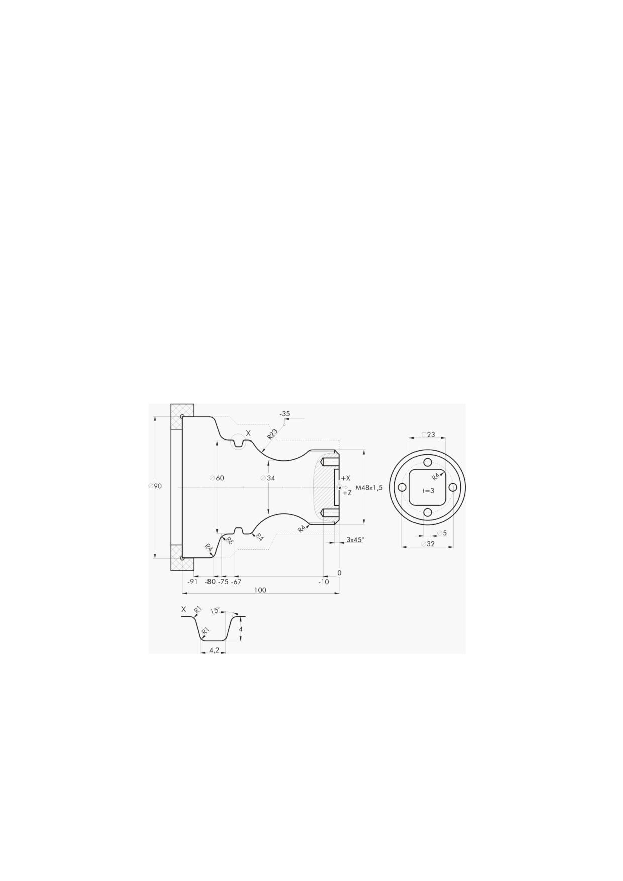
Figure 8-1
Workshop drawing - Example 3:
Turning made easy with ShopTurn
Training Documents, 09/2011, 6FC5095-0AB80-1BP1
113
Example 3: Guide shaft
8.2 Face turning
Preparation
Perform the following steps without help:
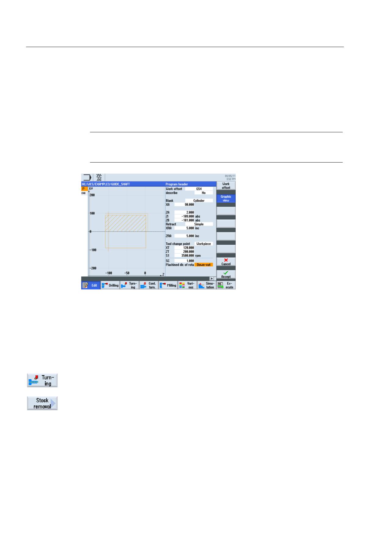
1. Create a new workpiece with the name 'EXAMPLE3'.
2. Create a new step sequence program with the name 'GUIDE_SHAFT'.
3. Fill in the program header (see illustration below).
Note
Although you can do this for any blank, select the Cylinder blank here. ShopTurn ignores
this input and selects an arbitrary blank.
Figure 8-2
Creating a program header
8.2
Face turning
Operating sequences
Proceed as follows to create a new program and face turn the blank to Z0:
Select the Turning softkey.
Select the Stock removal softkey.
Select the ROUGHING_T80 A tool.
Turning made easy with ShopTurn
114
Training Documents, 09/2011, 6FC5095-0AB80-1BP1
Example 3: Guide shaft
8.2 Face turning
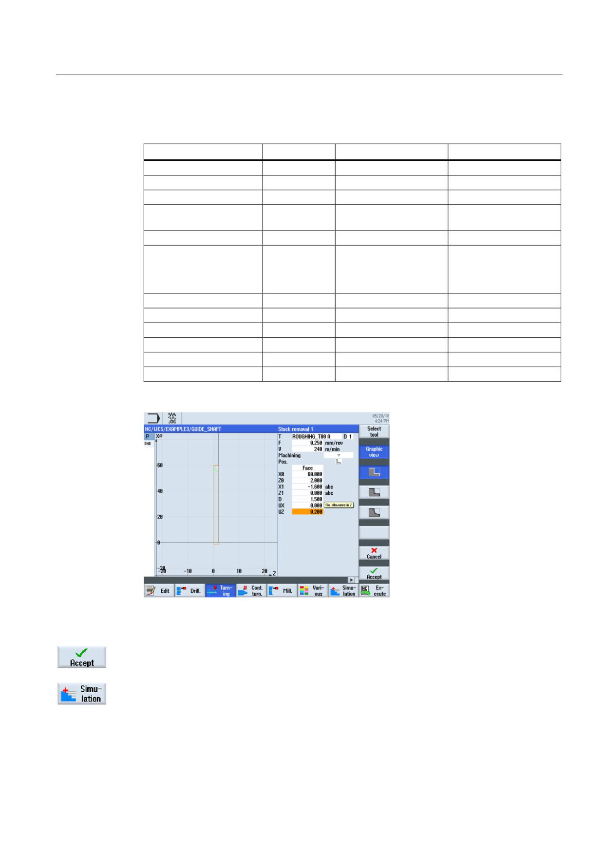
Enter the following values in the interactive screenform:
Field
Value
Selection via toggle key
Notes
F
0.25
V
240 m/min
X
Machining
Finishing
X
Position
(see illustration
X
below)
Machining direction
Chart
X
X0
60
Since the blank has a
diameter of 60mm, you
must also set dimension
X0 to 60 in this work step.
Z0
2
X1
-1.6 abs
X
Z1
0.0 abs
X
D
1.5
UX
0.0
UZ
0.2
Figure 8-3
Face turning the workpiece
Accept the entered values.
Start the simulation to check the work step.
Turning made easy with ShopTurn
Training Documents, 09/2011, 6FC5095-0AB80-1BP1
115
Example 3: Guide shaft
8.3 Creating any blank contour
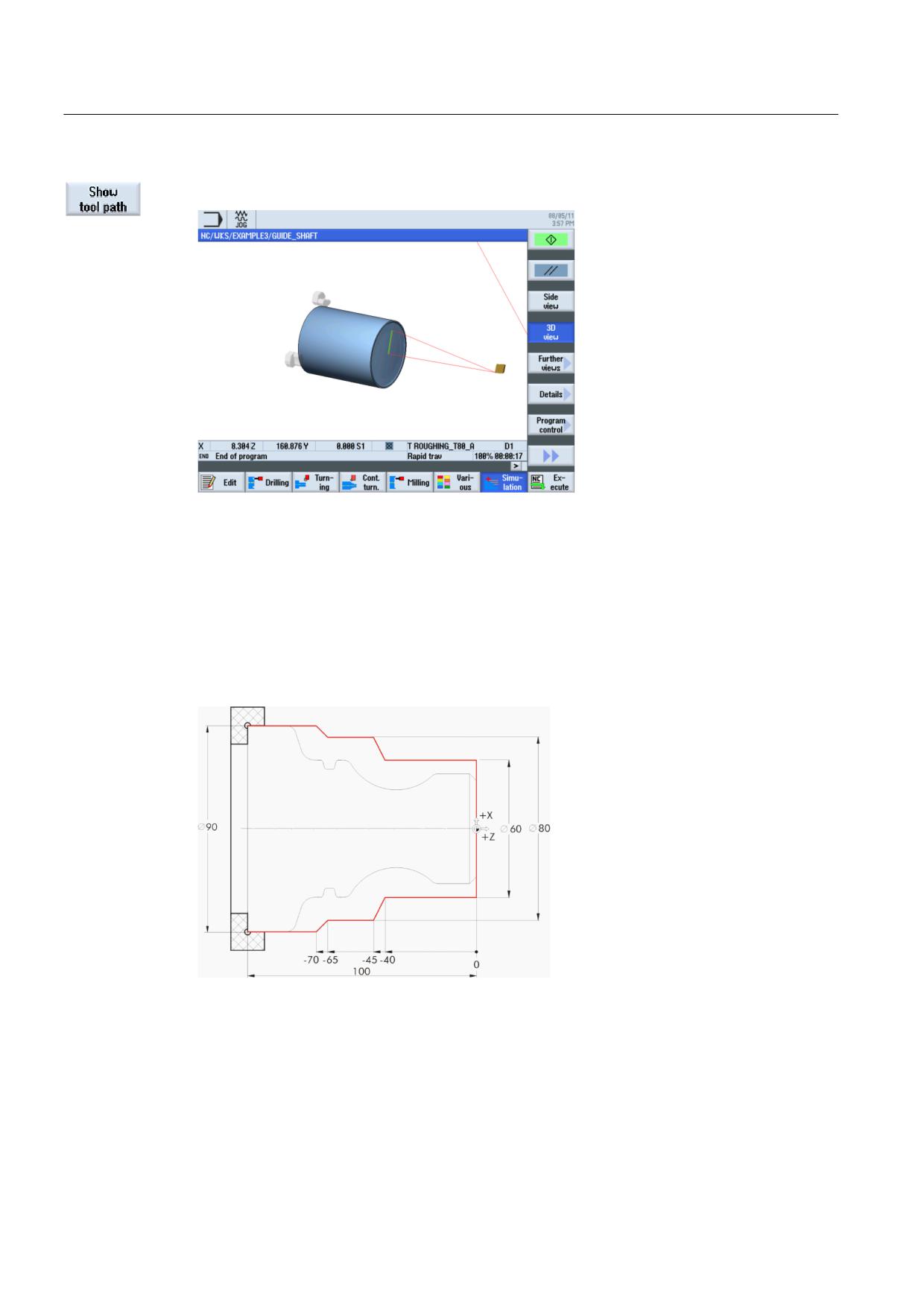
You can activate the display of traversing paths via the extended menu.
Figure 8-4
Face turning simulation
8.3
Creating any blank contour
Operating sequences
Enter the following blank contour without help:
Turning made easy with ShopTurn
116
Training Documents, 09/2011, 6FC5095-0AB80-1BP1
Example 3: Guide shaft
8.3 Creating any blank contour
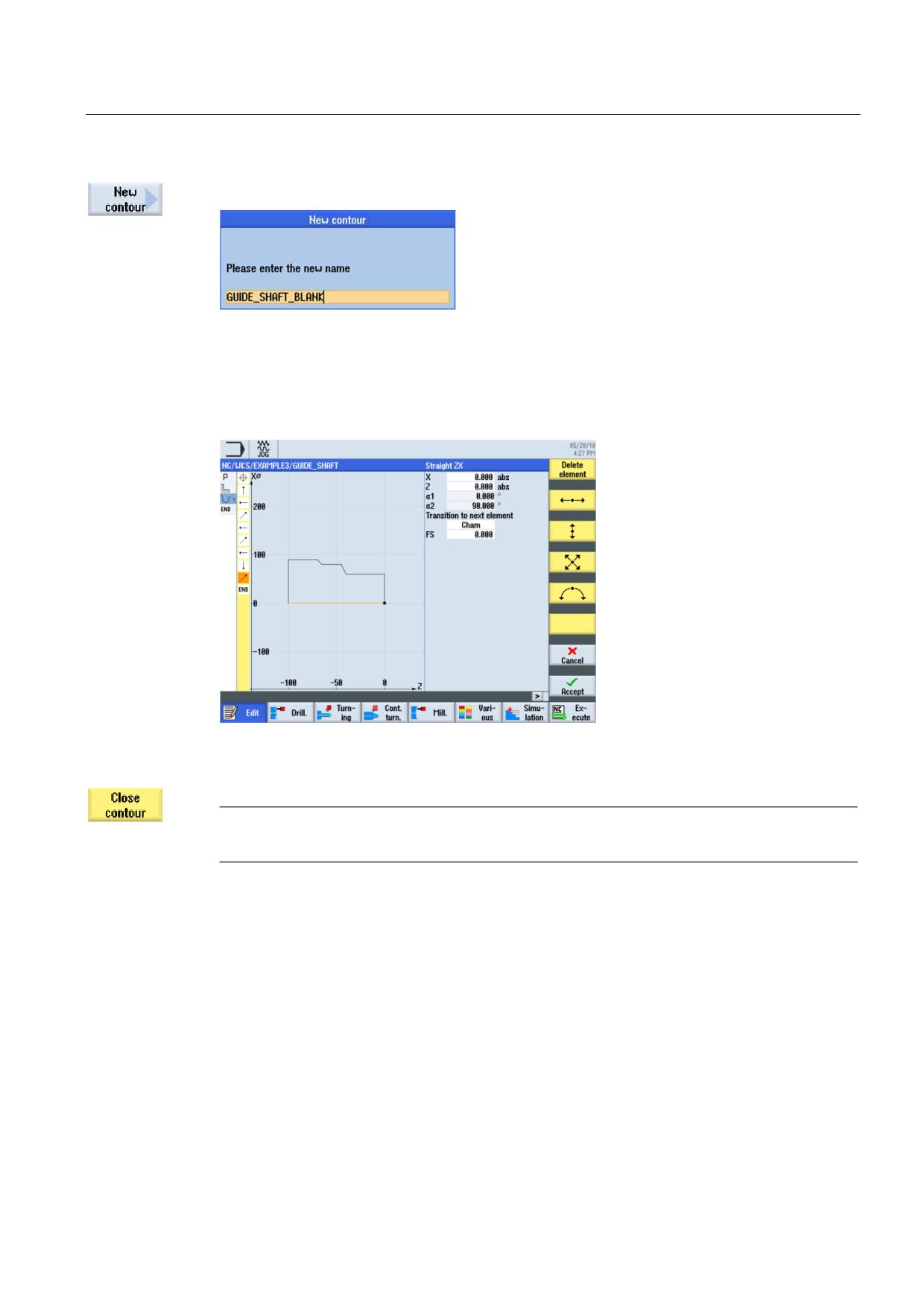
Select the New contour softkey. Enter the name 'GUIDE_SHAFT_BLANK' for the contour.
Figure 8-5
Creating the contour
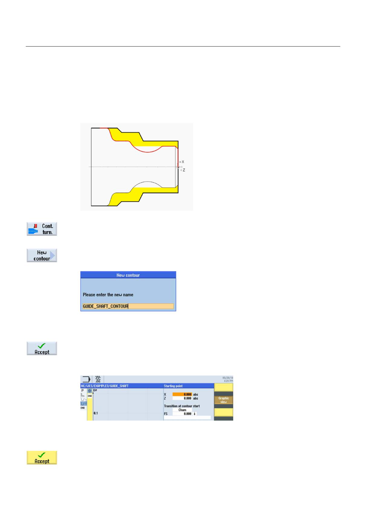
In the contour calculator, create the blank contour with the starting point at X0/Z0 (see
illustration below).
Figure 8-6
Any blank contour
Note
The contour must be closed.
Turning made easy with ShopTurn
Training Documents, 09/2011, 6FC5095-0AB80-1BP1
117
Example 3: Guide shaft
8.4 Creating the machined part contour and stock removal
8.4
Creating the machined part contour and stock removal
Operating sequences
Proceed as follows to enter the machined part contour:
Select the Contour turning softkey.
Select the New contour softkey. Enter the name 'GUIDE_SHAFT_CONTOUR' for the
contour.
Figure 8-7
Creating the contour
Confirm your input.
Since the blank was assigned to Z0 in the first work step, you can accept the starting point
X0/Z0 directly (see illustration below).
Figure 8-8
Specifying the contour starting point
Confirm your input.
Turning made easy with ShopTurn
118
Training Documents, 09/2011, 6FC5095-0AB80-1BP1
Example 3: Guide shaft
8.4 Creating the machined part contour and stock removal
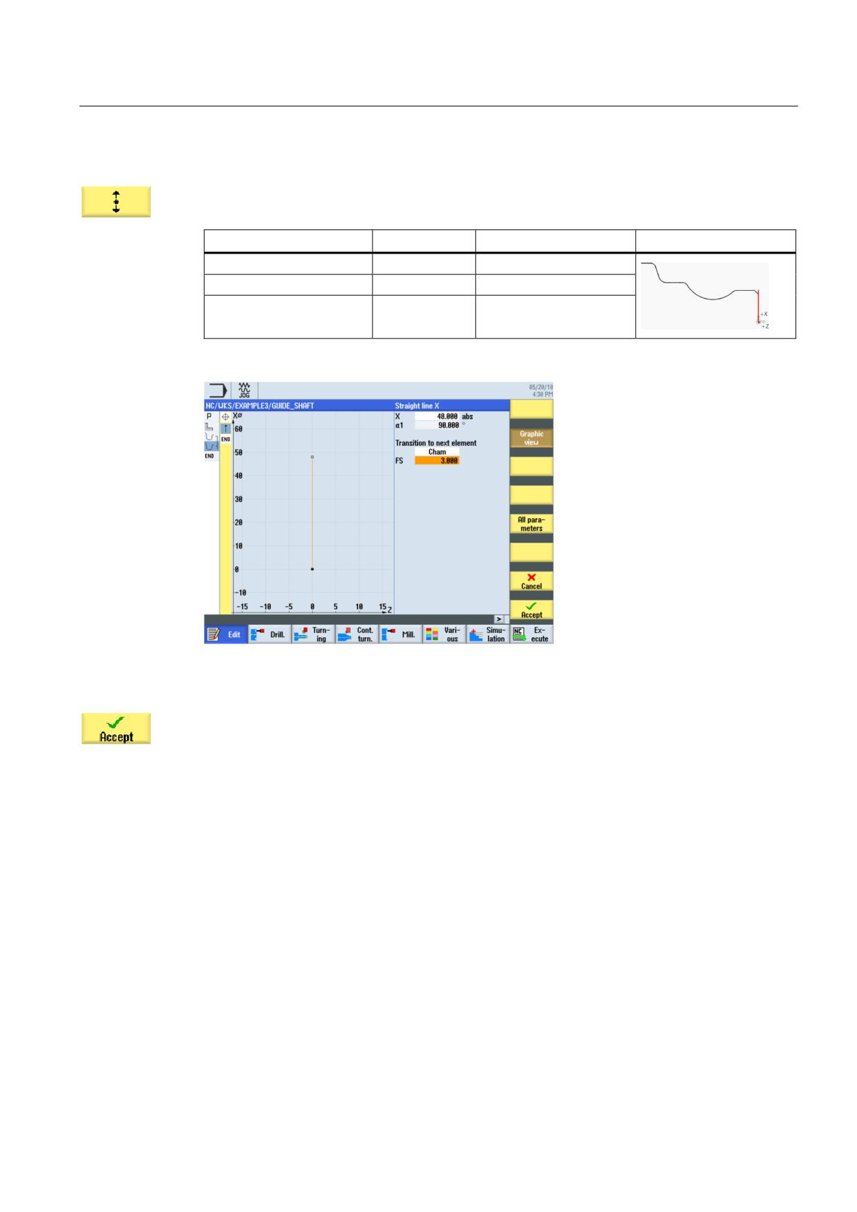
Enter the following values for the vertical straight line in the interactive screenform:
Field
Value
Selection via toggle key
Notes
X
48 abs
X
Transition to next element
Chamfer
X
R
3
Figure 8-9
Specifying the vertical straight line contour
Accept the entered values.
Turning made easy with ShopTurn
Training Documents, 09/2011, 6FC5095-0AB80-1BP1
119
Example 3: Guide shaft
8.4 Creating the machined part contour and stock removal
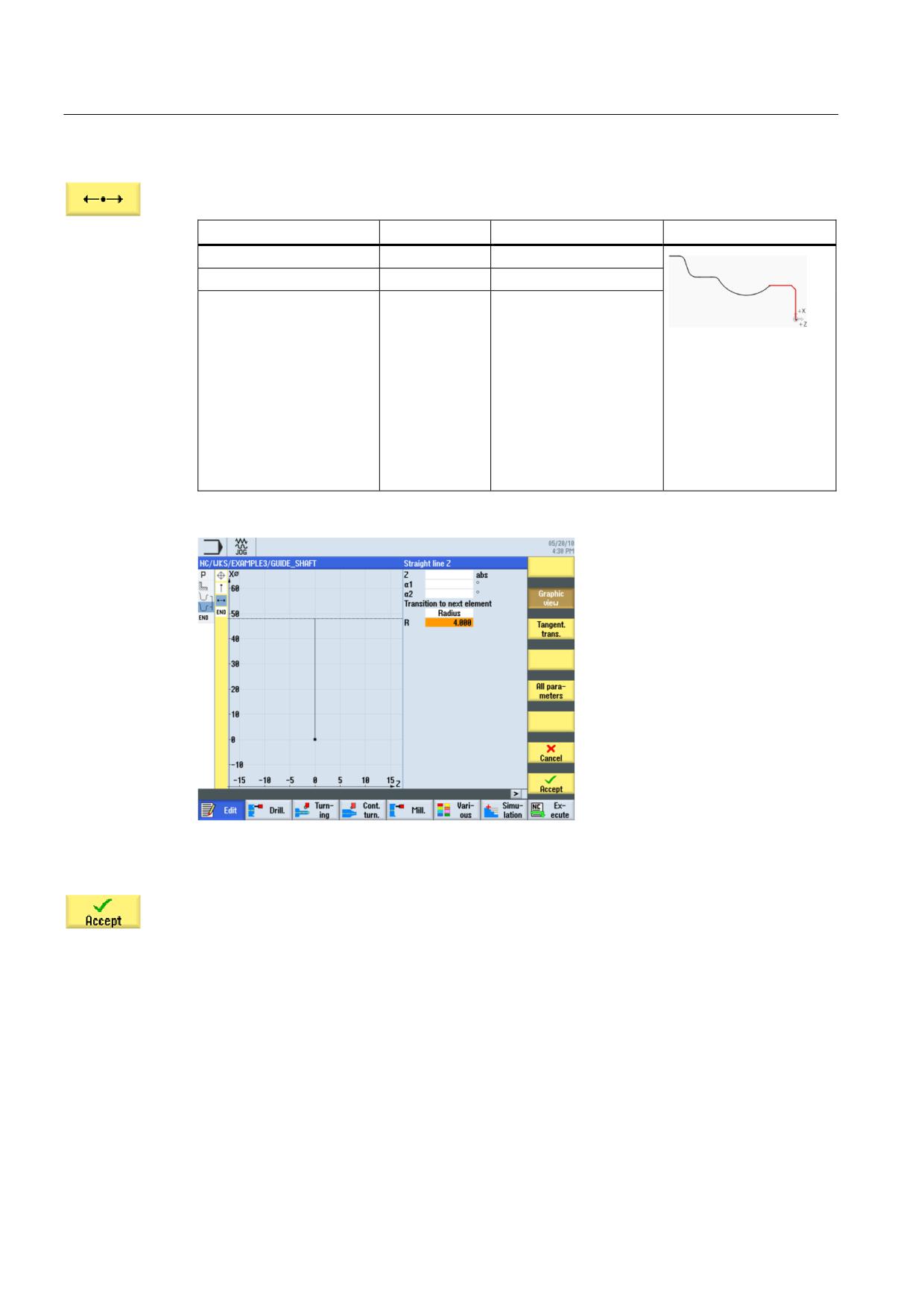
Enter the following values for the horizontal straight line in the interactive screenform:
Field
Value
Selection via toggle key
Notes
Z
Transition to next element
Radius
X
R
4
The end point of the
horizontal straight line is
unknown. Enter only the
transition to the next
element with R4. The end
point of the straight line is
calculated automatically
from the subsequent
contour constructions.
Figure 8-10 Specifying the horizontal straight line contour
Accept the entered values.
Turning made easy with ShopTurn
120
Training Documents, 09/2011, 6FC5095-0AB80-1BP1
Example 3: Guide shaft
8.4 Creating the machined part contour and stock removal
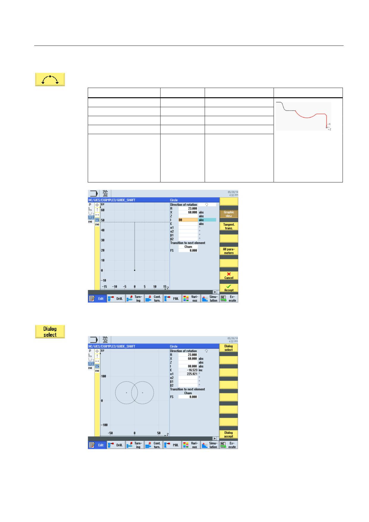
Enter the following values for the next section in the interactive screenform:
Field
Value
Selection via toggle key
Notes
Direction of rotation
Right
X
R
23
X
60 abs
X
Z
If several solutions are
I
80 abs
X
possible when entering
the contour data (e.g. in
the case of circular arcs
here), you can select
these via the Selection
dialog softkey.
Figure 8-11 Specifying the arc contour
Select the recommended solution in accordance with the below illustration.
Figure 8-12 Selecting an arc contour
Turning made easy with ShopTurn
Training Documents, 09/2011, 6FC5095-0AB80-1BP1
121