SINUMERIK 840D sl. Training. Operate - Turning (2016-2020) - page 27
Example 3: Guide shaft
8.4 Creating the machined part contour and stock removal
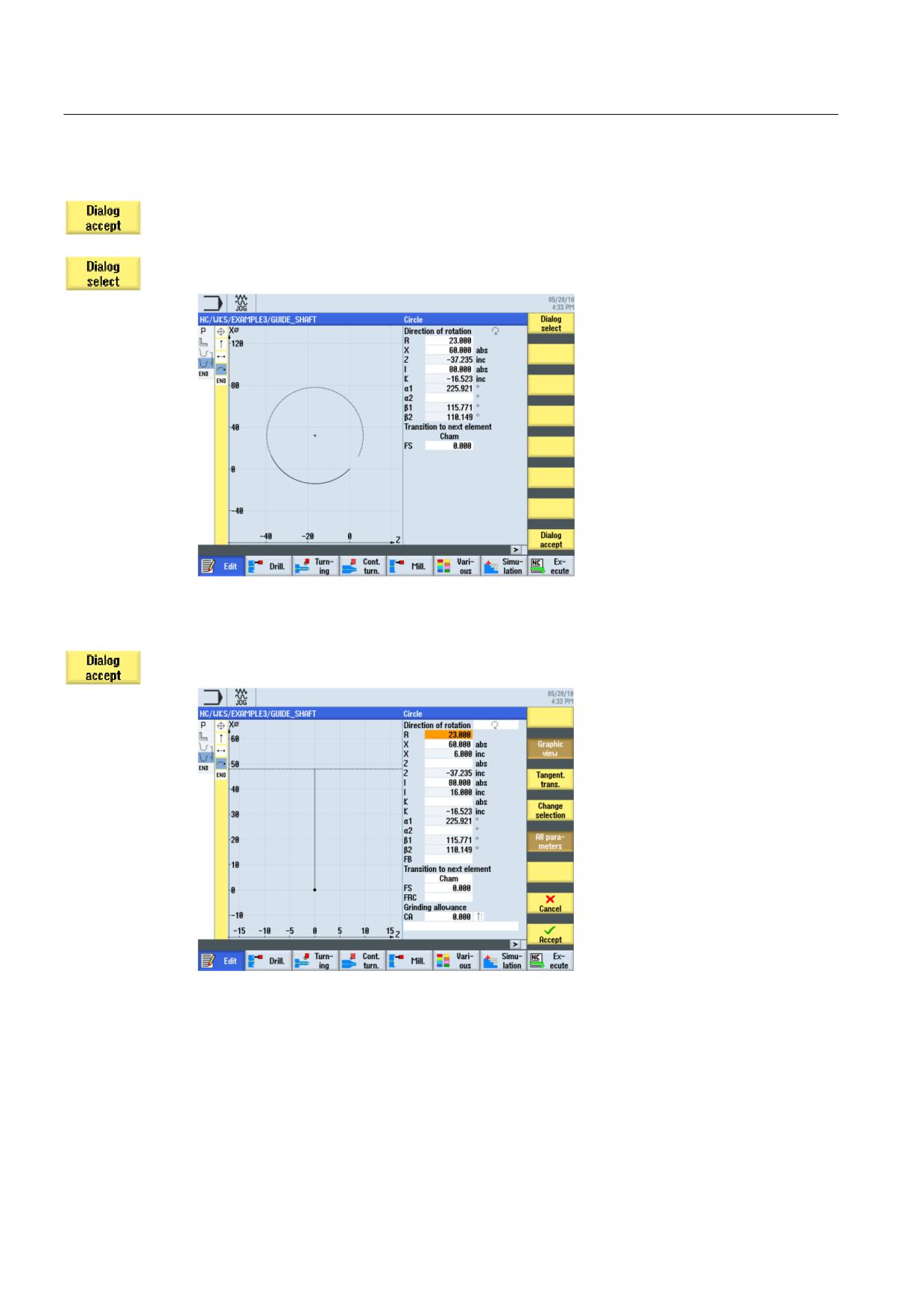
Select the desired construction, then accept.
Select the recommended solution in accordance with the below illustration.
Figure 8-13 Selecting an arc contour
Select the desired construction, then accept.
Figure 8-14 Accepting the selected arc contour
Turning made easy with ShopTurn
122
Training Documents, 09/2011, 6FC5095-0AB80-1BP1
Example 3: Guide shaft
8.4 Creating the machined part contour and stock removal
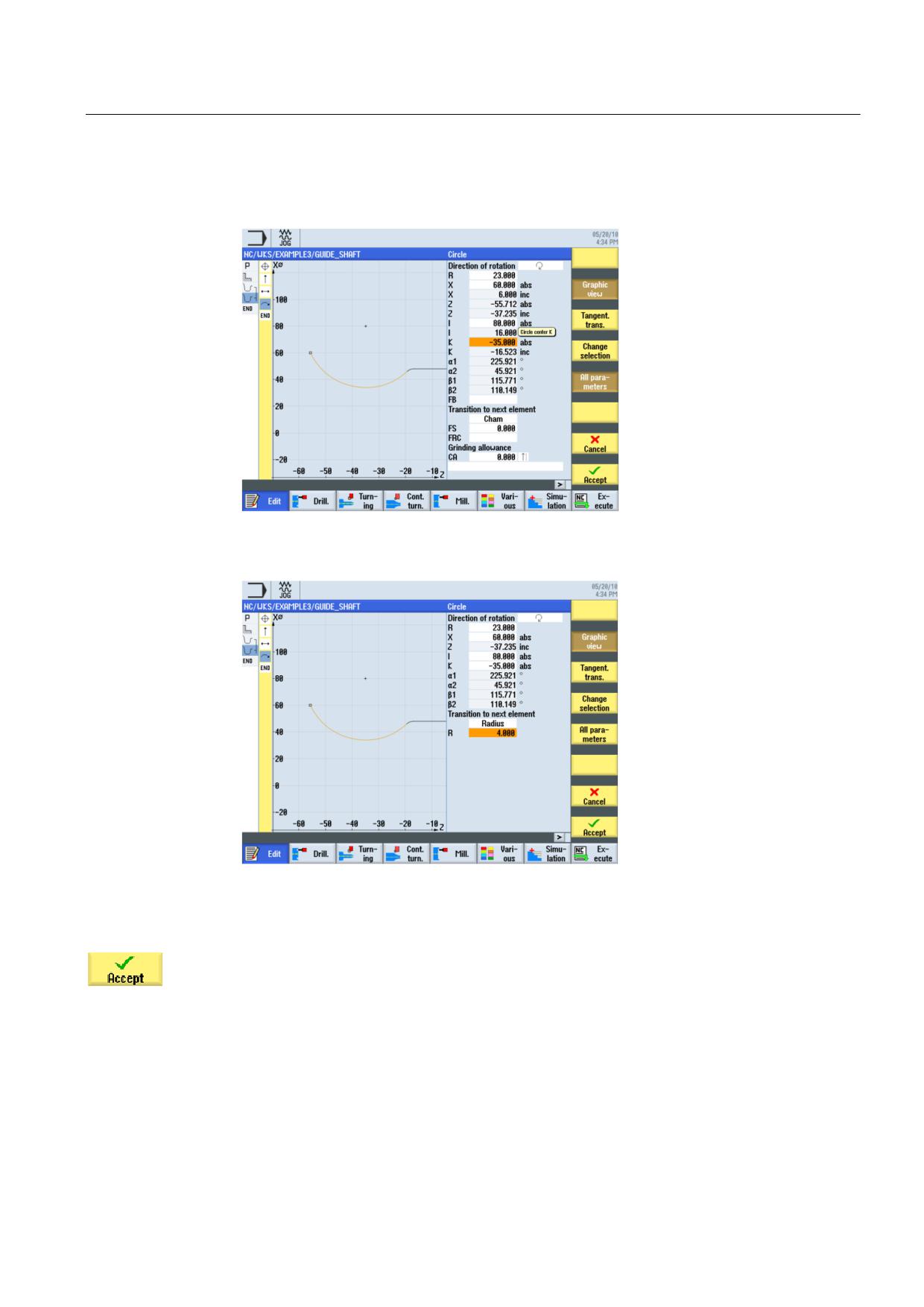
To complete the arc, proceed as follows:
1. Enter center point K-35 (absolute dimension).
Figure 8-15 Specifying the arc contour center point
2. Enter the transition to the next element with R4.
Figure 8-16 Specifying the arc contour radius
You can use the existing contour data and the calculated selection options to construct the
arc and the straight line (with unknown end point).
Accept the contour section.
Turning made easy with ShopTurn
Training Documents, 09/2011, 6FC5095-0AB80-1BP1
123
Example 3: Guide shaft
8.4 Creating the machined part contour and stock removal
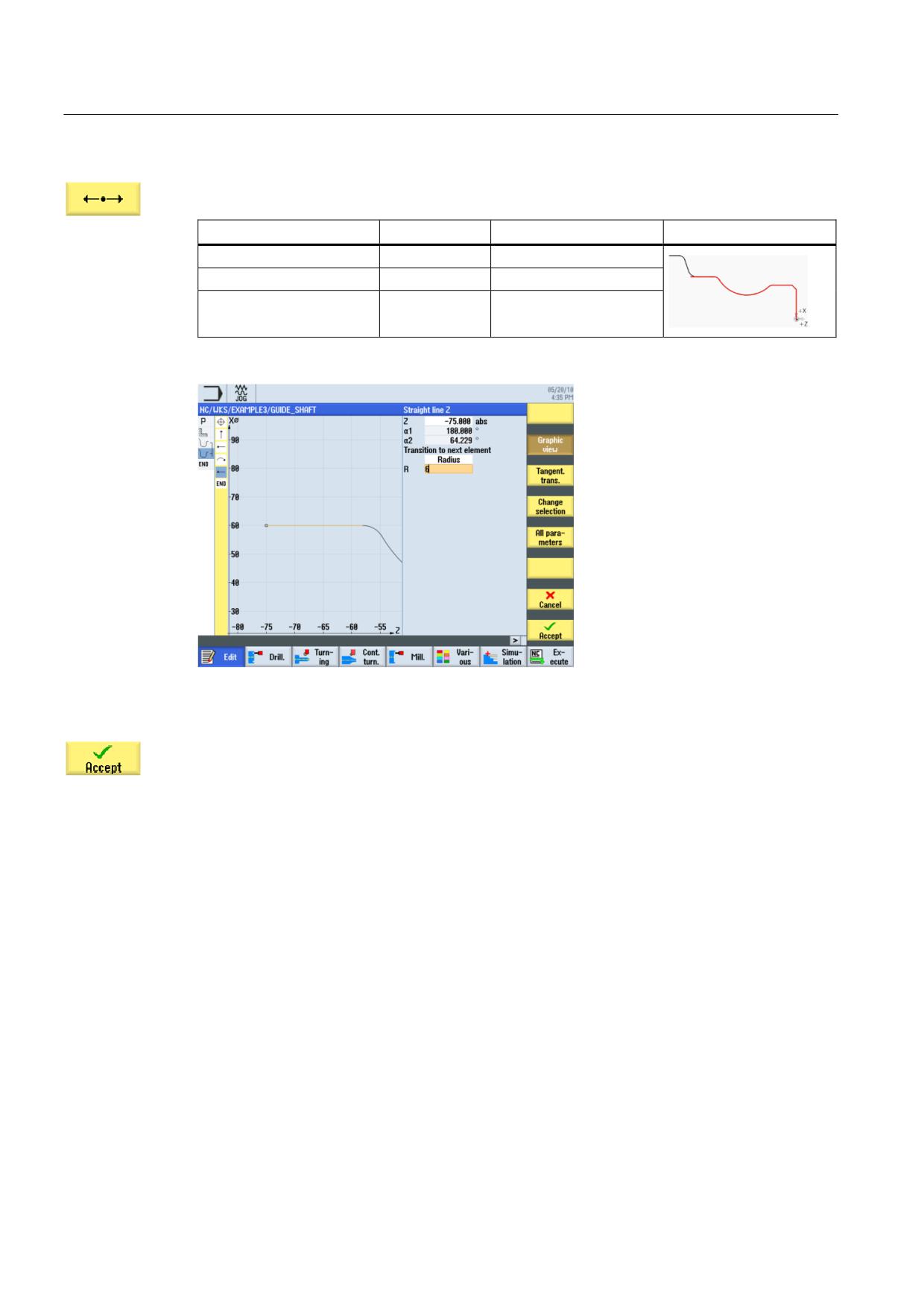
Enter the following values for the horizontal straight line in the interactive screenform:
Field
Value
Selection via toggle key
Notes
Z
-75 abs
X
Transition to next element
Radius
X
R
6
Figure 8-17 Specifying the horizontal straight line contour
Accept the entered values.
Turning made easy with ShopTurn
124
Training Documents, 09/2011, 6FC5095-0AB80-1BP1
Example 3: Guide shaft
8.4 Creating the machined part contour and stock removal
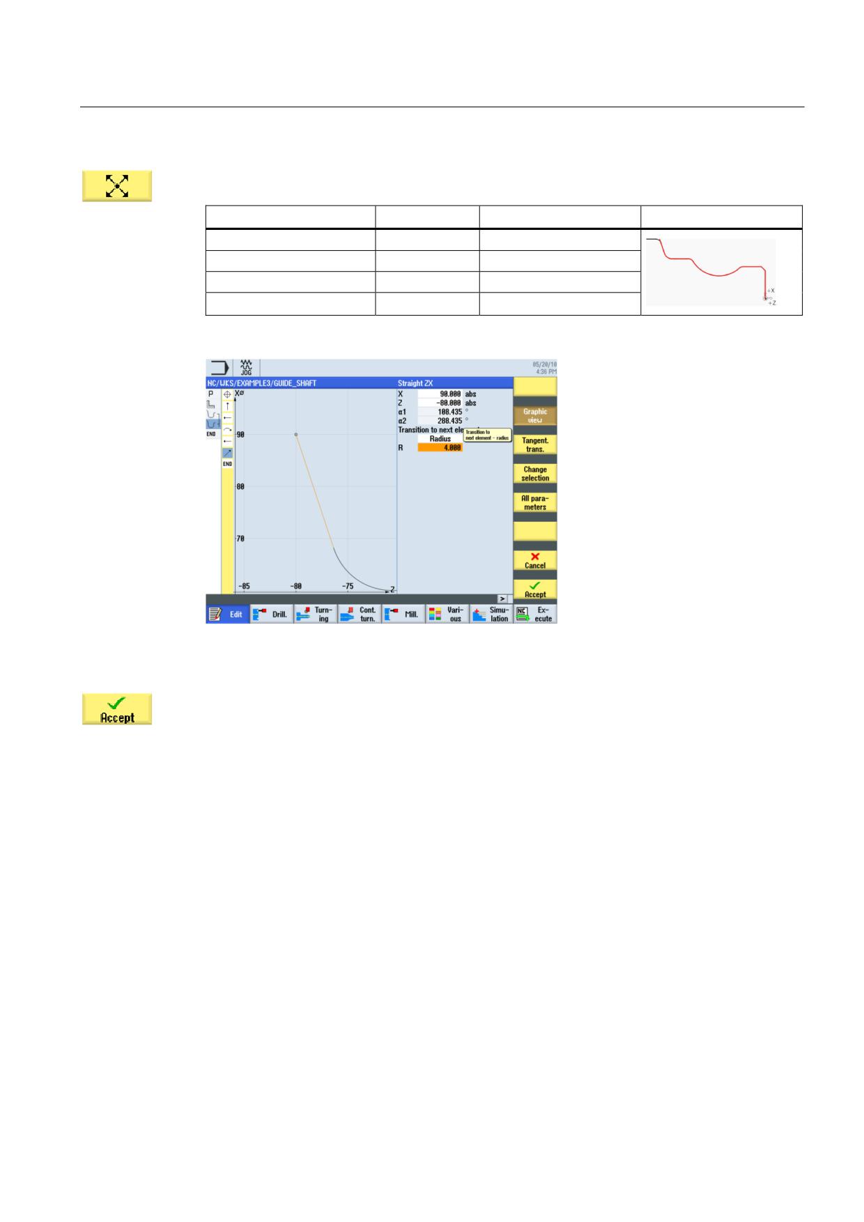
Enter the following values for the inclined straight line in the interactive screenform:
Field
Value
Selection via toggle key
Notes
X
90 abs
X
Z
-80 abs
X
Transition to next element
Radius
X
R
4
Figure 8-18 Specifying the inclined straight line contour
Accept the entered values.
Turning made easy with ShopTurn
Training Documents, 09/2011, 6FC5095-0AB80-1BP1
125
Example 3: Guide shaft
8.4 Creating the machined part contour and stock removal
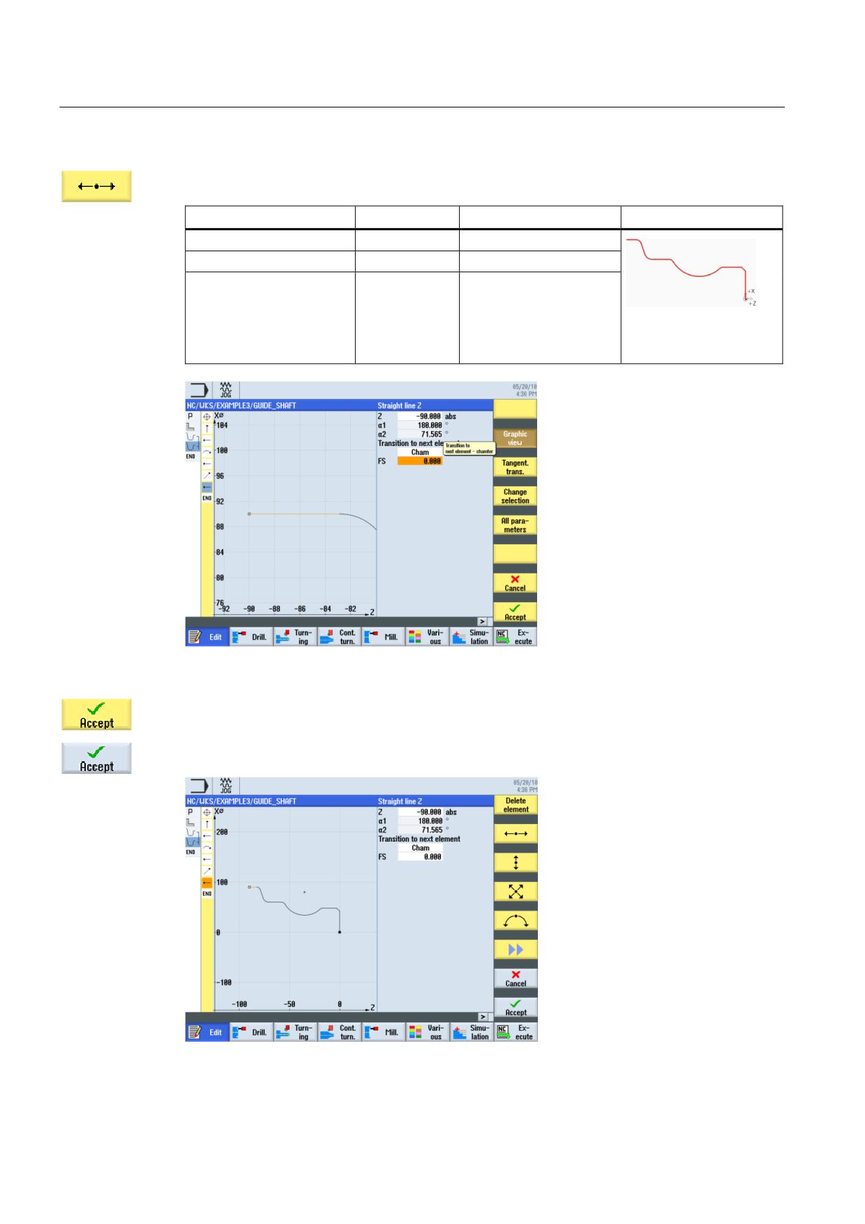
Enter the following values for the horizontal straight line in the interactive screenform:
Field
Value
Selection via toggle key
Notes
Z
-90 abs
X
Transition to next element
Chamfer
X
FS
0
To prevent damage to the
chuck, end the
construction at Z-90.
Figure 8-19 Specifying the horizontal straight line contour
Accept the entered values.
Accept the contour into your process plan.
Figure 8-20 Accepting the contour
Turning made easy with ShopTurn
126
Training Documents, 09/2011, 6FC5095-0AB80-1BP1
Example 3: Guide shaft
8.4 Creating the machined part contour and stock removal
Stock removal
In the following work step you will perform contour stock removal.
To this end, proceed as follows:
Select the Stock removal softkey.
Open the tool list and select the ROUGHING_T80 A tool.
Accept the tool into your program.
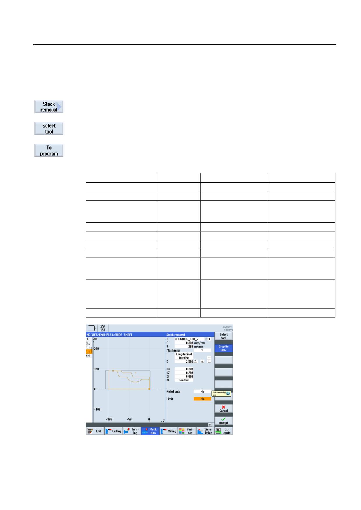
Enter the following values for roughing in the interactive screenform:
Field
Value
Selection via toggle key
Notes
F
0.3
V
260 m/min
X
Machining
longitudinal
X
external
X
roughing
X
D
2.5
UX
0.2
UZ
0.2
DI
0.0
BL
Contour
X
The blank description
must be switched to
contour here.
Relief cuts
No
X
To ensure that the recess
of radius 23 is not
machined, you must
switch to No.
Set machining area limits
No
X
Figure 8-21 Contour stock removal
Turning made easy with ShopTurn
Training Documents, 09/2011, 6FC5095-0AB80-1BP1
127
Example 3: Guide shaft
8.5 Residual stock removal
Accept the entered values. Both contours and the work step are linked together following
acceptance.
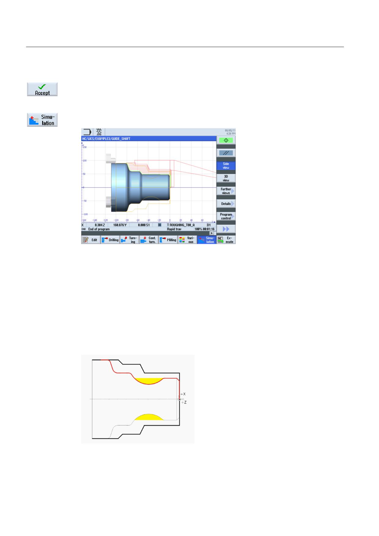
Select the Simulation softkey.
Figure 8-22 Contour stock removal simulation (with display of the traversing paths).
The traversing paths in the simulation clearly indicate how the previously constructed blank
is taken into consideration.
8.5
Residual stock removal
Operating sequences
Proceed as follows to cut the residual material:
Turning made easy with ShopTurn
128
Training Documents, 09/2011, 6FC5095-0AB80-1BP1
Example 3: Guide shaft
8.5 Residual stock removal
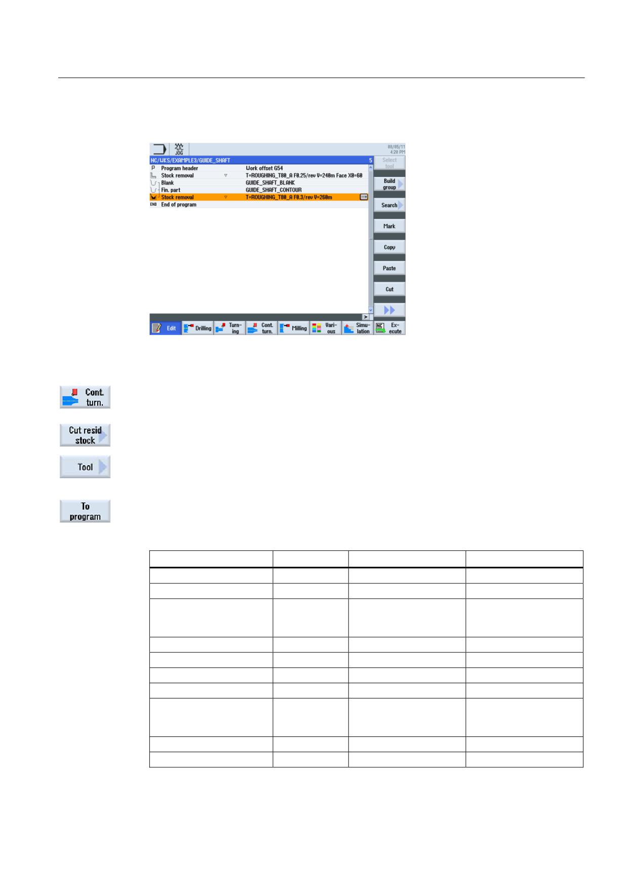
The following illustration shows the process plan up to roughing machining:
Figure 8-23 Process plan including roughing machining
Select the Contour turning softkey.
Select the Residual stock removal softkey.
Open the tool list and select the BUTTON_TOOL_8 tool.
Accept the tool into your program.
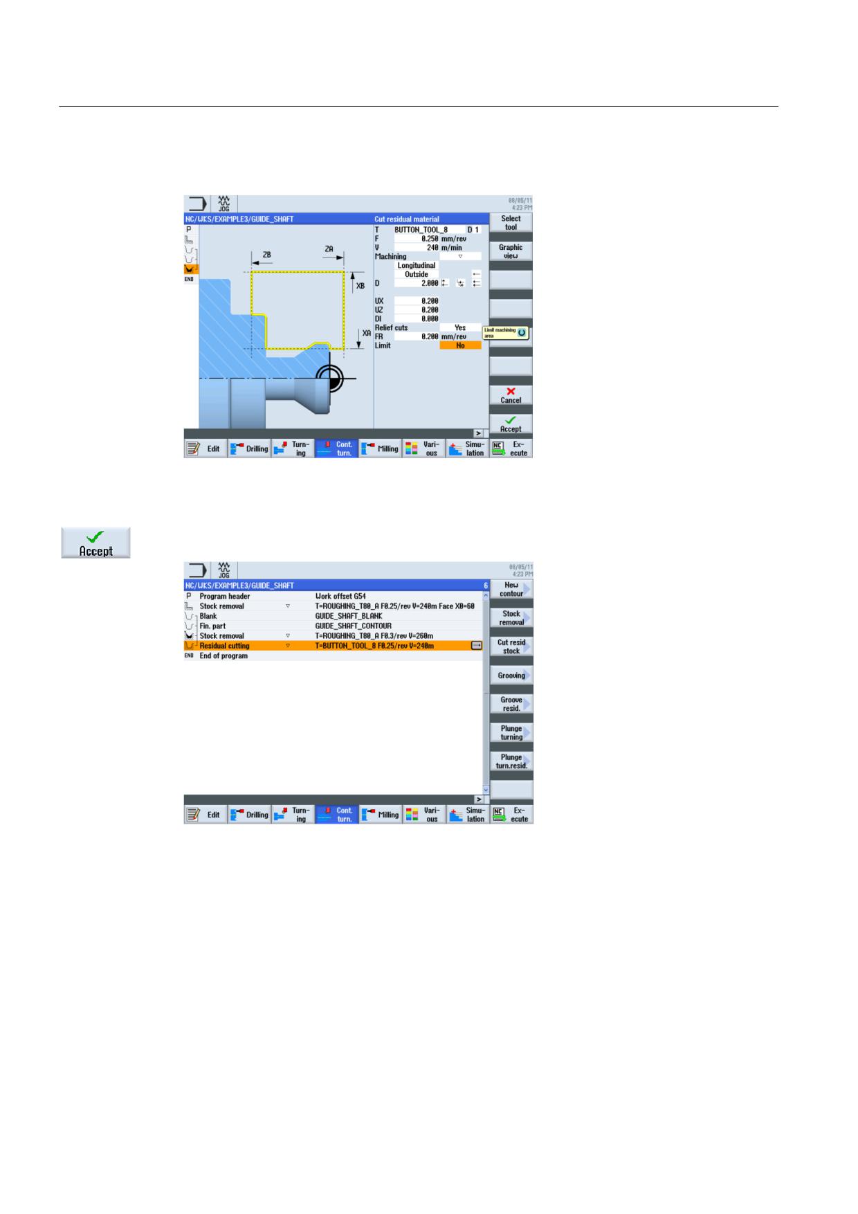
Enter the following values for residual stock removal in the interactive screenform:
Field
Value
Selection via toggle key
Notes
F
0.25
V
240 m/min
X
Machining
longitudinal
X
external
X
roughing
X
D
2.0
UX
0.2
UZ
0.2
DI
0.0
Relief cuts
Yes
X
Machining with relief cuts
must be switched to Yes
here.
FR
0.2
Set machining area limits
No
X
Turning made easy with ShopTurn
Training Documents, 09/2011, 6FC5095-0AB80-1BP1
129
Example 3: Guide shaft
8.5 Residual stock removal
Figure 8-24 Cutting contour residual material
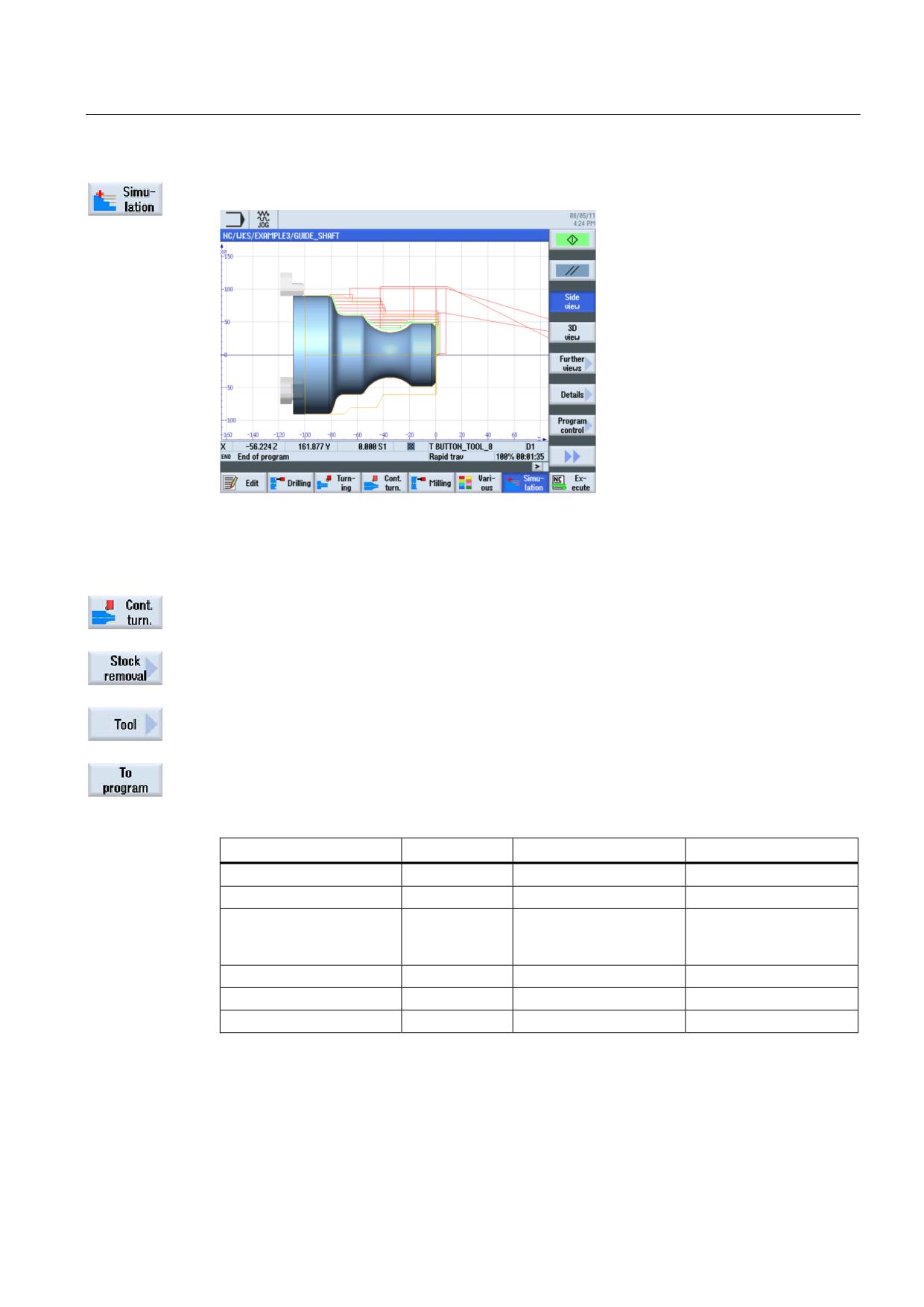
Accept the entered values. After acceptance, the list of work steps looks like this:
Figure 8-25 Process plan with residual stock removal
Turning made easy with ShopTurn
130
Training Documents, 09/2011, 6FC5095-0AB80-1BP1
Example 3: Guide shaft
8.5 Residual stock removal
Start the simulation.
Figure 8-26 Residual stock removal simulation
After roughing the contour, it must then be finished.
Select the Contour turning softkey.
Select the Stock removal softkey.
Open the tool list and select the FINISHING_T35 A tool.
Accept the tool into your program.
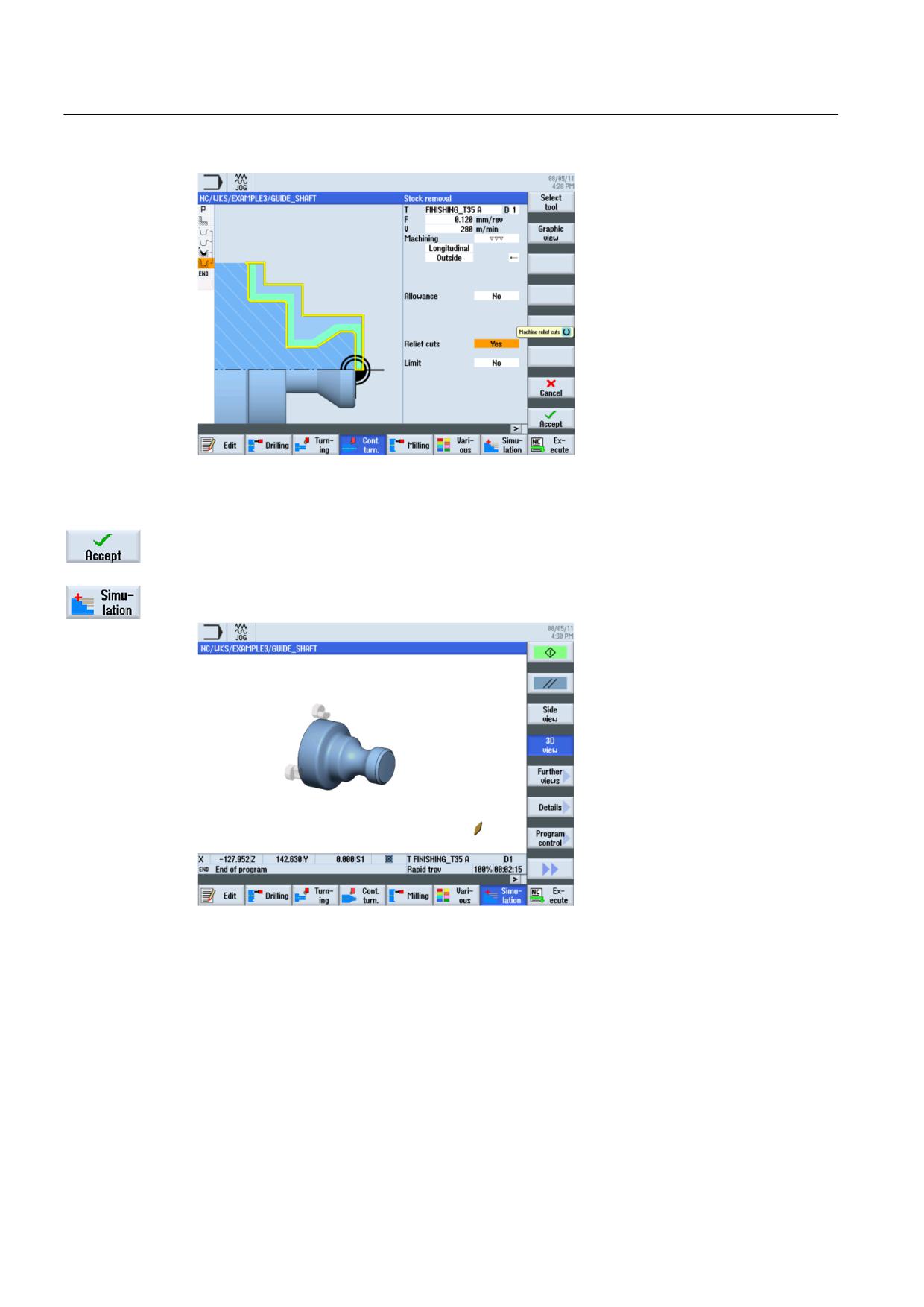
Enter the following values for finishing in the interactive screenform:
Field
Value
Selection via toggle key
Notes
F
0.12
S
280 m/min
X
Machining
longitudinal
X
external
X
finishing
X
Allowance
No
X
Relief cuts
Yes
X
Set machining area limits
No
X
Turning made easy with ShopTurn
Training Documents, 09/2011, 6FC5095-0AB80-1BP1
131
Example 3: Guide shaft
8.5 Residual stock removal
Figure 8-27 Finishing the contour
Accept the entered values.
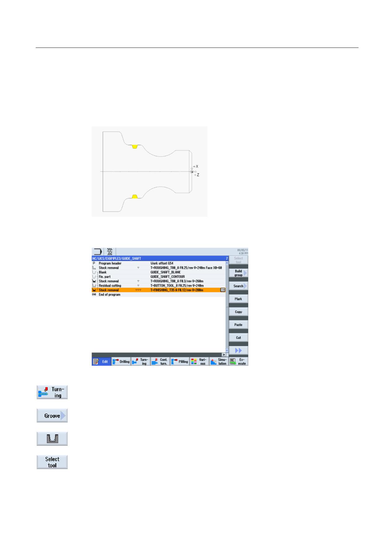
Start the simulation.
Figure 8-28 Finishing simulation - 3D view
Turning made easy with ShopTurn
132
Training Documents, 09/2011, 6FC5095-0AB80-1BP1
Example 3: Guide shaft
8.6 Groove
8.6
Groove
Operating sequences
Proceed as follows to create a groove:
After residual stock removal, the list of work steps looks like this:
Figure 8-29 Process plan following stock removal
Select the Turning softkey.
Select the Groove softkey.
Select the second groove shape (groove 2).
Open the tool list and select PLUNGE_CUTTER_3 A.
Turning made easy with ShopTurn
Training Documents, 09/2011, 6FC5095-0AB80-1BP1
133
Example 3: Guide shaft
8.6 Groove
Accept the tool into your program.
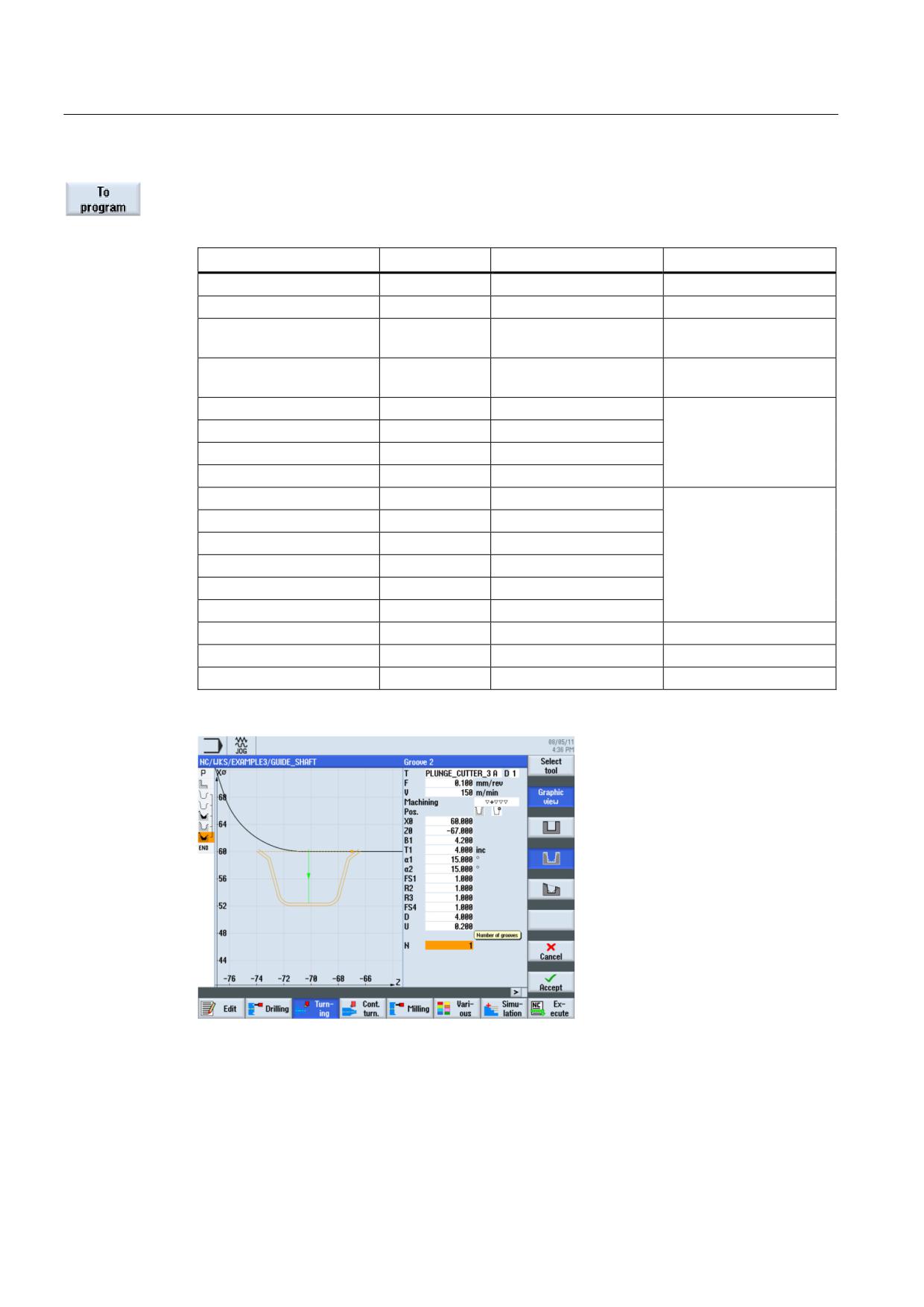
Enter the following values for the groove in the interactive screenform:
Field
Value
Selection via toggle key
Notes
F
0.1 mm/rev
V
150 m/min
X
Machining
Roughing +
X
finishing
Position
see illustration
X
below
X0
60
Here, you enter the
position and allowance of
Z0
-67
the groove.
B1
4.2
X (field)
T1
4 inc
X
α1
15
Here, you enter the flank
angle and rounding at the
α2
15
corners.
FS1
1
X (field)
R2
1
X (field)
R3
1
X (field)
FS4
1
X (field)
D
4
U
0.2
X (field)
N
1
Figure 8-30 Creating a groove
Turning made easy with ShopTurn
134
Training Documents, 09/2011, 6FC5095-0AB80-1BP1
Example 3: Guide shaft
8.6 Groove
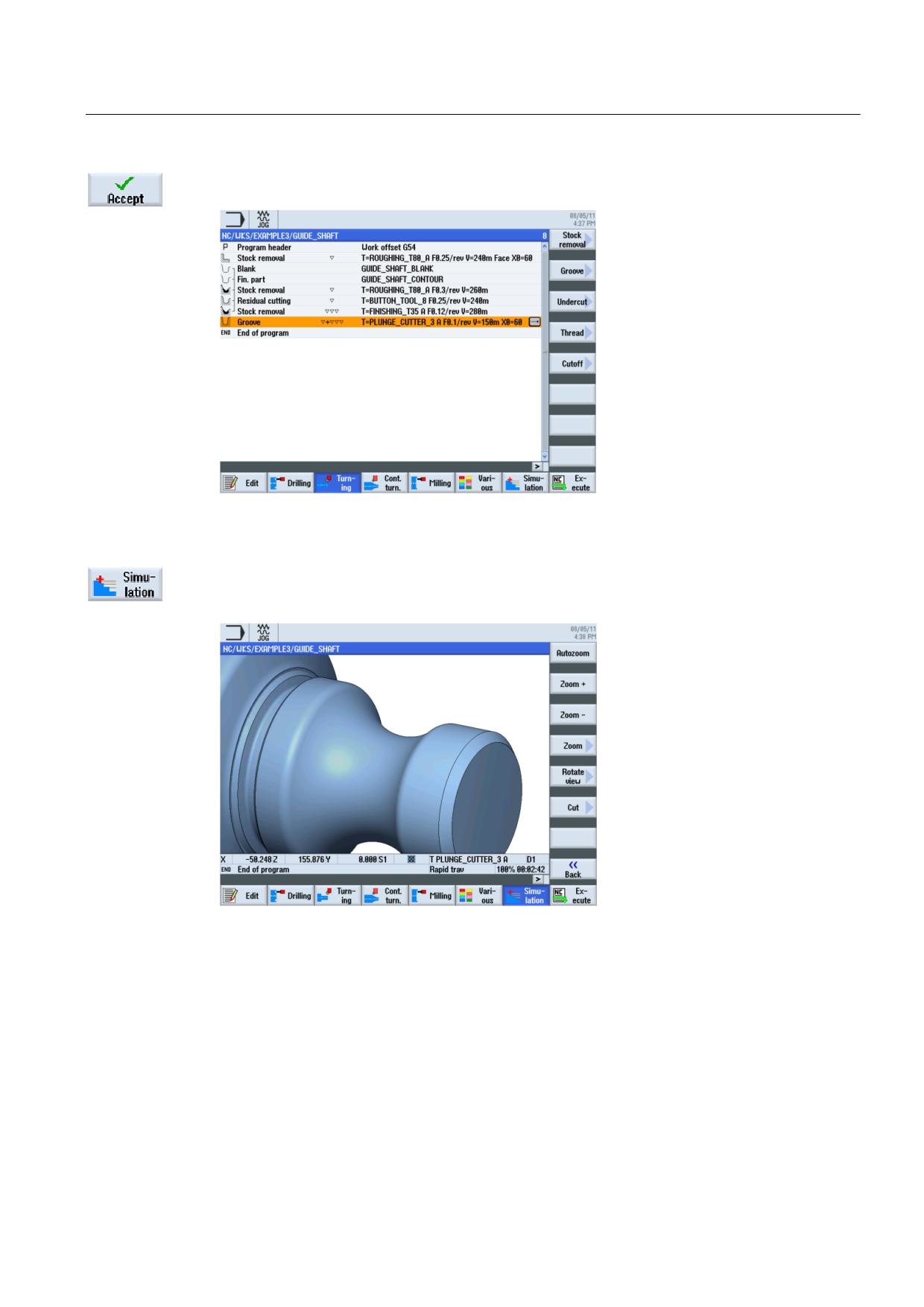
Accept the entered values. After acceptance, the list of work steps looks like this:
Figure 8-31 Process plan including groove
Start the simulation. You can check subareas of the workpiece using the Magnifying glass
softkey.
Figure 8-32 Simulation - 3D view (magnifying glass)
Turning made easy with ShopTurn
Training Documents, 09/2011, 6FC5095-0AB80-1BP1
135
Example 3: Guide shaft
8.7 Thread
8.7
Thread
Operating sequences
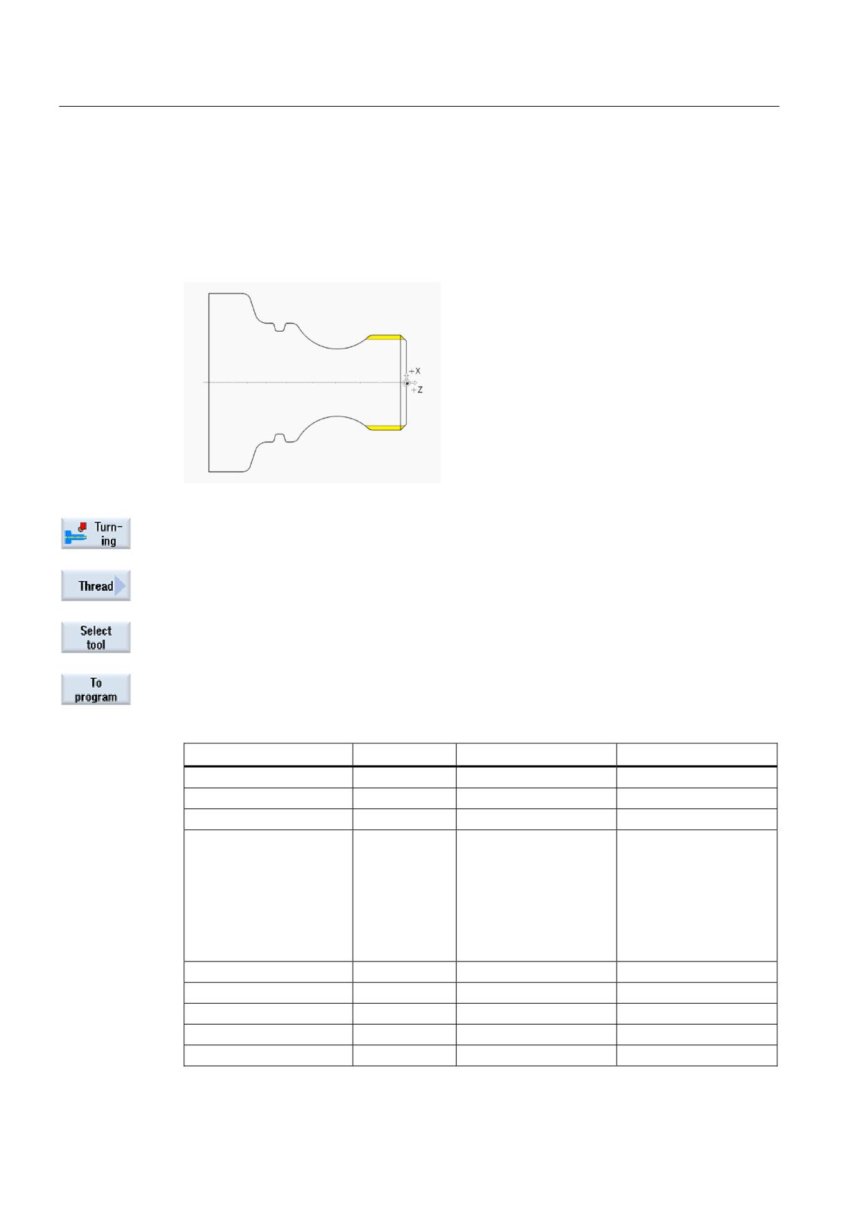
Proceed as follows to create a thread.
Select the Turning softkey.
Select the Thread softkey.
Open the tool list and select THREADING_T1.5.
Accept the tool into your program.
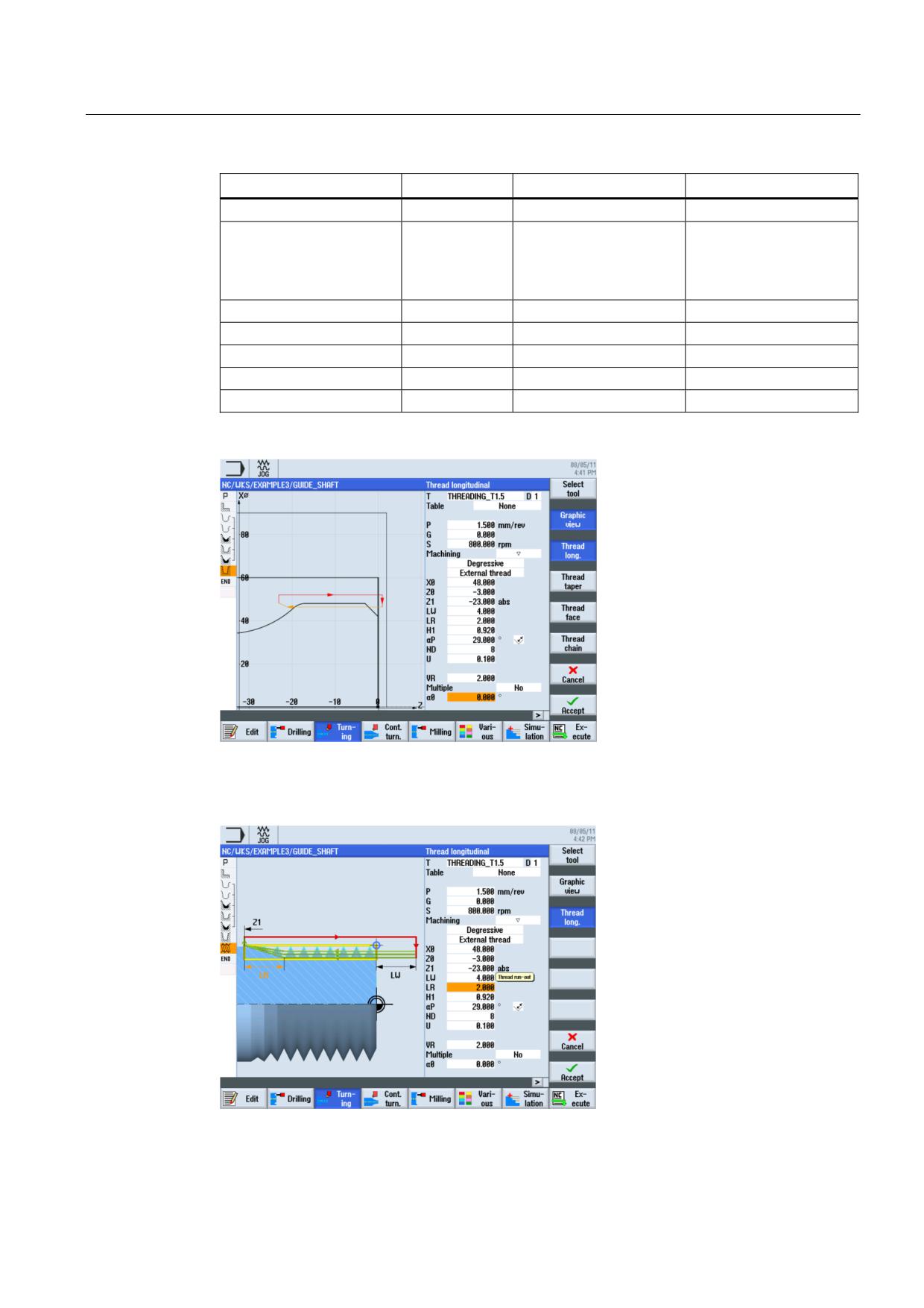
Enter the following values for the thread in the interactive screenform:
Field
Value
Selection via toggle key
Notes
P
1.5 mm/rev
X
G
0
S
800 rpm
X
Machining
Roughing
X
The thread is created with
the diminishing setting.
Diminishing
X
This setting causes the
External thread
X
cutting division to be
reduced for each cut, and
so ensures that the
cutting cross-section
remains constant.
X0
48
Z0
-3
Z1
-23 abs
X
LW
4
X (field)
LR
2
Turning made easy with ShopTurn
136
Training Documents, 09/2011, 6FC5095-0AB80-1BP1
Example 3: Guide shaft
8.7 Thread
Field
Value
Selection via toggle key
Notes
H1
0.92
αP
29
X (field)
Infeed with
X
alternating
flanks
ND
8
X (field)
U
0.1
VR
2
Multiple threads
No
X
α0
0
Figure 8-33 Producing a thread
Switch to the help display when necessary.
Figure 8-34 Help display - thread exit
Turning made easy with ShopTurn
Training Documents, 09/2011, 6FC5095-0AB80-1BP1
137
Example 3: Guide shaft
8.8 Drilling
Accept the entered values.
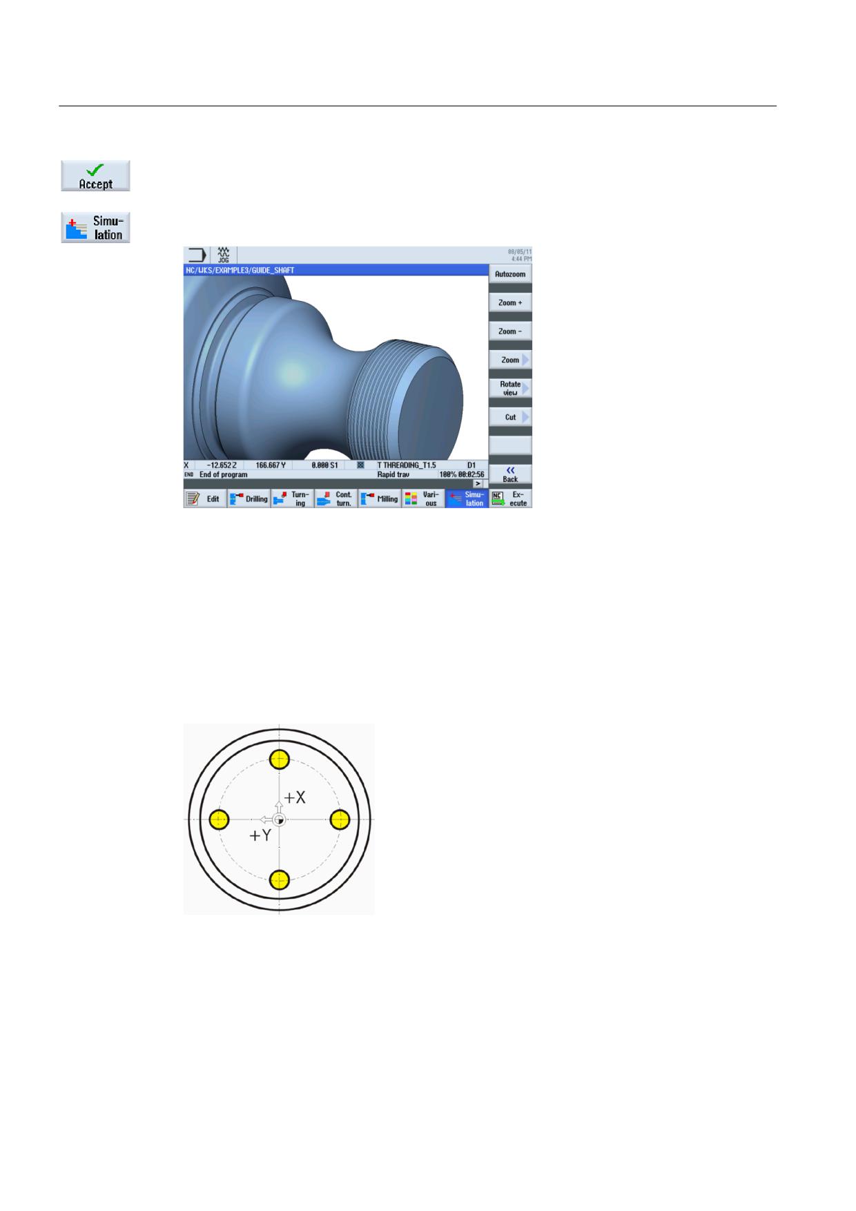
Start the simulation. You can check subareas of the workpiece using the Details softkey.
Figure 8-35 3D view simulation - details
8.8
Drilling
Operating sequences
Proceed as follows to create drill holes on the front face (C axis or complete machining
sequence).
Turning made easy with ShopTurn
138
Training Documents, 09/2011, 6FC5095-0AB80-1BP1
Example 3: Guide shaft
8.8 Drilling
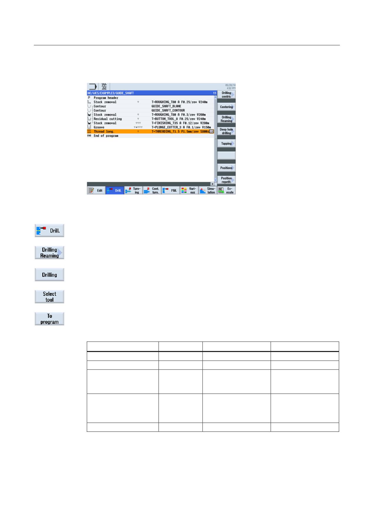
After the thread has been created, the list of work steps looks like this:
Figure 8-36 Process plan following thread creation
Select the Drilling softkey.
Select the Drilling Reaming softkey. The workpiece is drilled directly, i.e. without centering.
Select the Drilling softkey.
Open the tool list and select DRILL_5.
Accept the tool into your program.
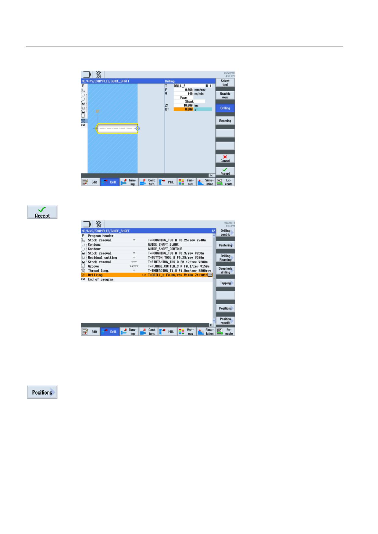
Enter the following values for the drill hole in the interactive screenform:
Field
Value
Selection via toggle key
Notes
F
0.06 mm/rev
X
V
140 m/min
X
Face
X
Shank
X
The depth reference is
switched to Shank.
Z1
10 inc
X
The hole depth can be
entered as 10mm
incremental or -10mm
absolute.
DT
0 s
X
Turning made easy with ShopTurn
Training Documents, 09/2011, 6FC5095-0AB80-1BP1
139
Example 3: Guide shaft
8.8 Drilling
Figure 8-37 Drilling
Accept the entered values. After acceptance, the list of work steps looks like this:
Figure 8-38 Process plan following drilling
During the drilling work step, an open connector appears in the list of work steps. This is
automatically linked to the drilling positions in the next step.
Select the Positions softkey.
Turning made easy with ShopTurn
140
Training Documents, 09/2011, 6FC5095-0AB80-1BP1
Example 3: Guide shaft
8.8 Drilling
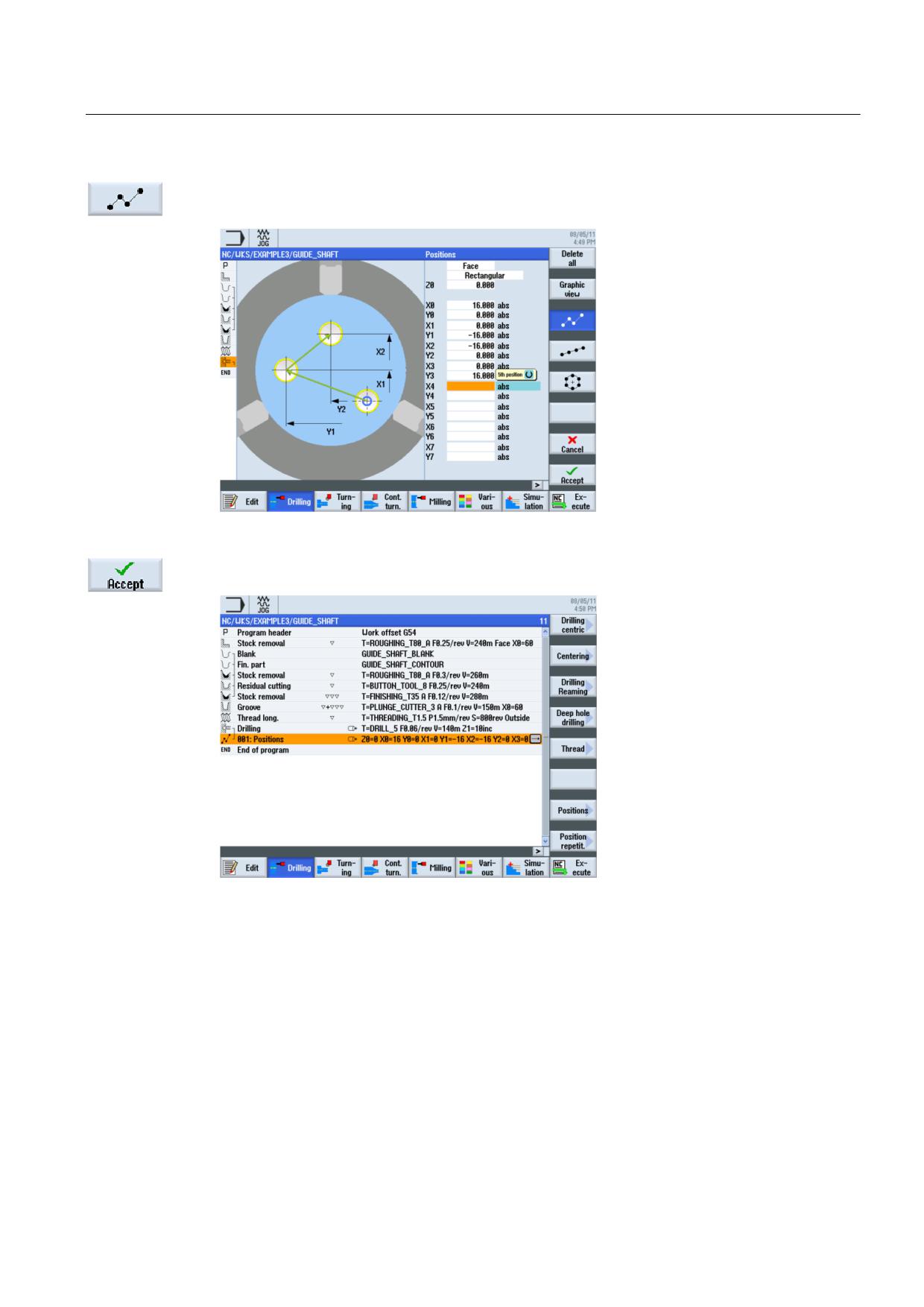
For the purposes of the exercise, the four drill holes are entered as single positions. A
simpler solution here would be to use the position circle.
Figure 8-39 Entering the positions
Accept the entered values. After acceptance, the list of work steps looks like this:
Figure 8-40 Process plan following input of the position pattern
The drill holes are now linked to the drilling positions.
Turning made easy with ShopTurn
Training Documents, 09/2011, 6FC5095-0AB80-1BP1
141
Example 3: Guide shaft
8.8 Drilling
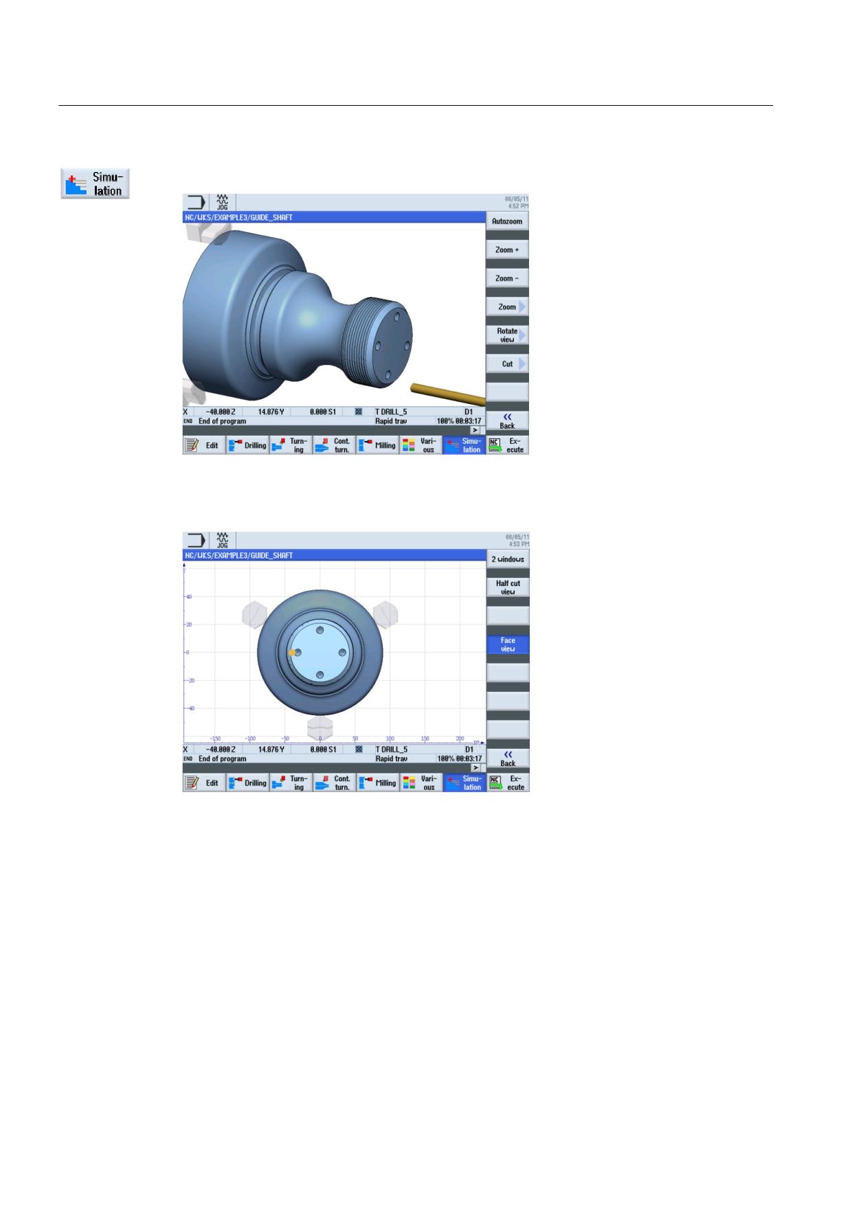
Start the simulation.
Figure 8-41 Simulation - 3D view
Figure 8-42 Simulation - front view
Turning made easy with ShopTurn
142
Training Documents, 09/2011, 6FC5095-0AB80-1BP1
Example 3: Guide shaft
8.9 Milling the rectangular pocket
8.9
Milling the rectangular pocket
Operating sequences
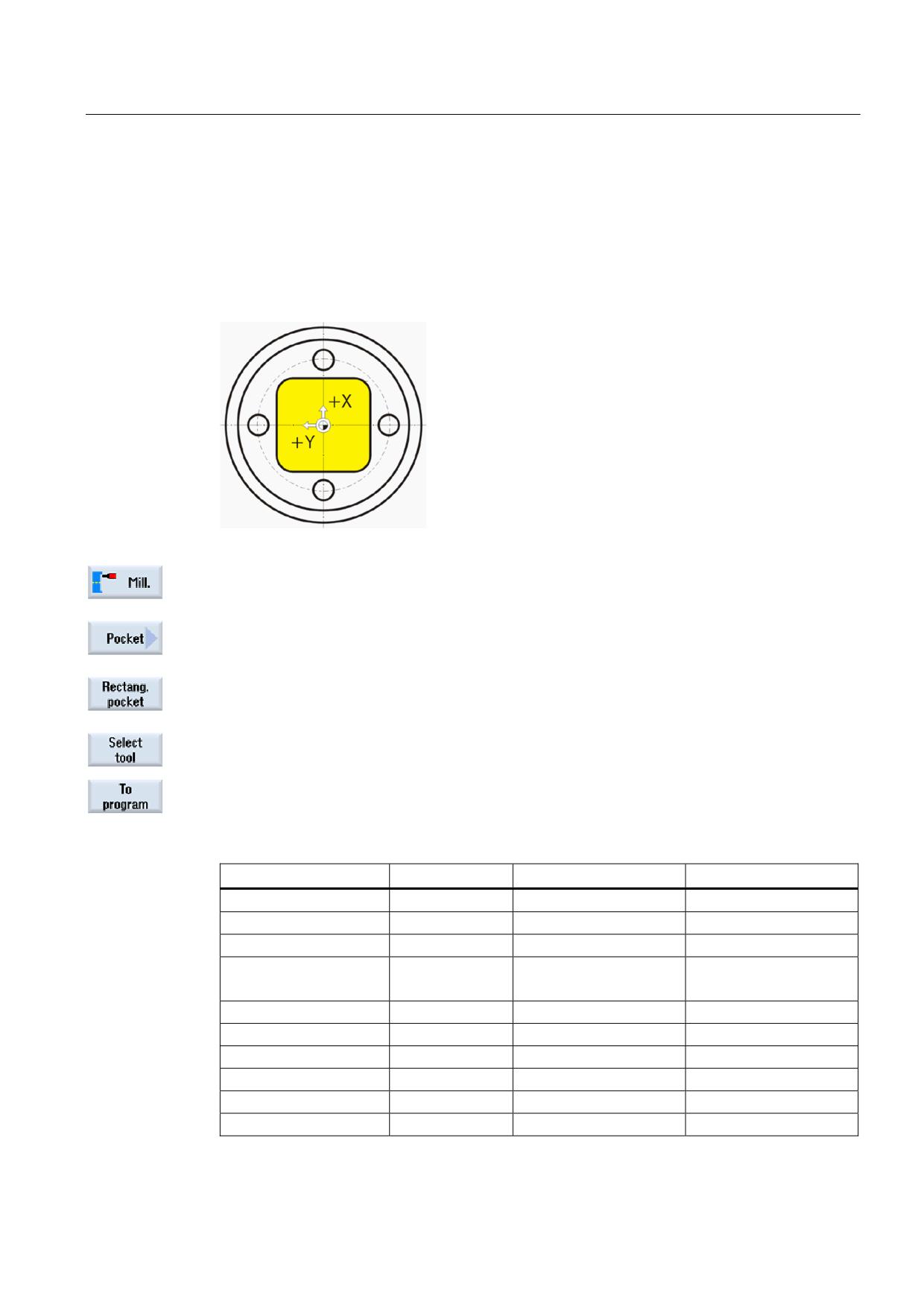
Proceed as follows to create a rectangular pocket on the front face (C axis or complete
machining sequence).
Select the Milling softkey.
Select the Pocket softkey.
Select the Rectangular pocket softkey.
Open the tool list and select CUTTER_8.
Accept the tool into your program.
Enter the following values for the rectangular pocket in the interactive screenform:
Field
Value
Selection via toggle key
Notes
F
0.03 mm/tooth
X
V
220 m/min
X
Face
X
Machining
Roughing
X
Single positions
X
X0
0
X (field)
Y0
0
X (field)
Z0
0
W
23
L
23
R
4
Turning made easy with ShopTurn
Training Documents, 09/2011, 6FC5095-0AB80-1BP1
143
Example 3: Guide shaft
8.9 Milling the rectangular pocket
Field
Value
Selection via toggle key
Notes
α0
0
Z1
3 inc
X
DXY
75%
X
DZ
1.5
UXY
0
UZ
0
Insertion
Helical
X
see insertion below
EP
1
ER
7
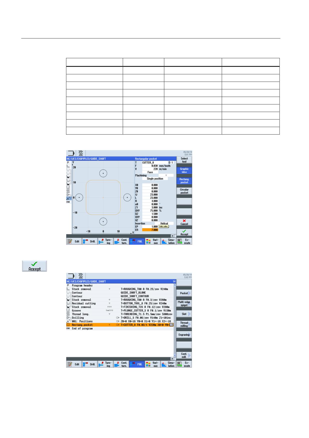
Figure 8-43 Producing a rectangular pocket
Accept the entered values. After acceptance, the list of work steps looks like this:
Figure 8-44 Process plan following rectangular pocket
Turning made easy with ShopTurn
144
Training Documents, 09/2011, 6FC5095-0AB80-1BP1
Example 3: Guide shaft
8.9 Milling the rectangular pocket
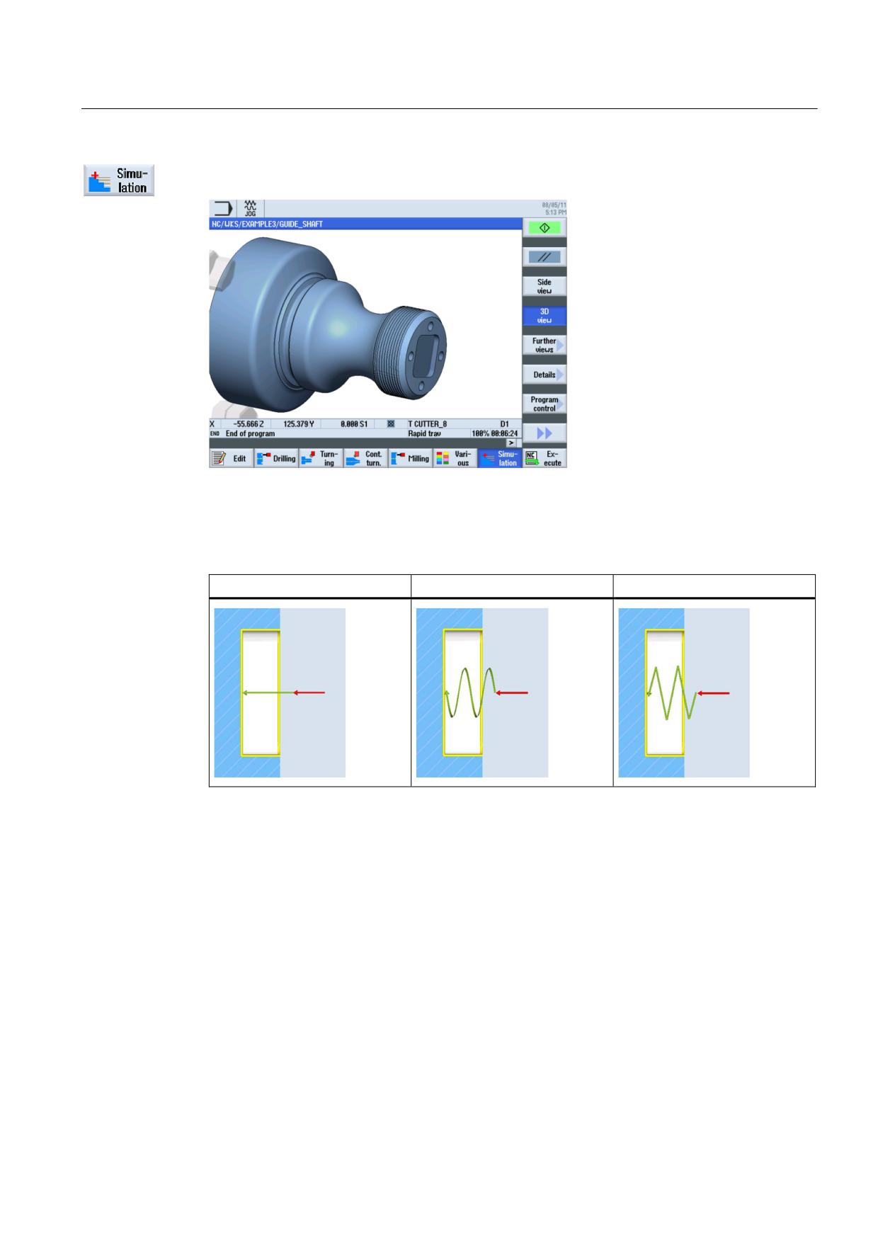
Start the simulation.
Figure 8-45 Simulation - 3D view
Insertion
Vertical insertion
Helical insertion
Oscillating insertion
Turning made easy with ShopTurn
Training Documents, 09/2011, 6FC5095-0AB80-1BP1
145
Example 3: Guide shaft
8.9 Milling the rectangular pocket
Turning made easy with ShopTurn
146
Training Documents, 09/2011, 6FC5095-0AB80-1BP1
Example 4: Hollow shaft
9
9.1
Overview
Learning objectives
In this section you will learn the following new functions. You will learn how to...
● perform internal machining on workpieces;
● work with the work step editor;
● create an undercut and
● an asymmetrical groove.
Task
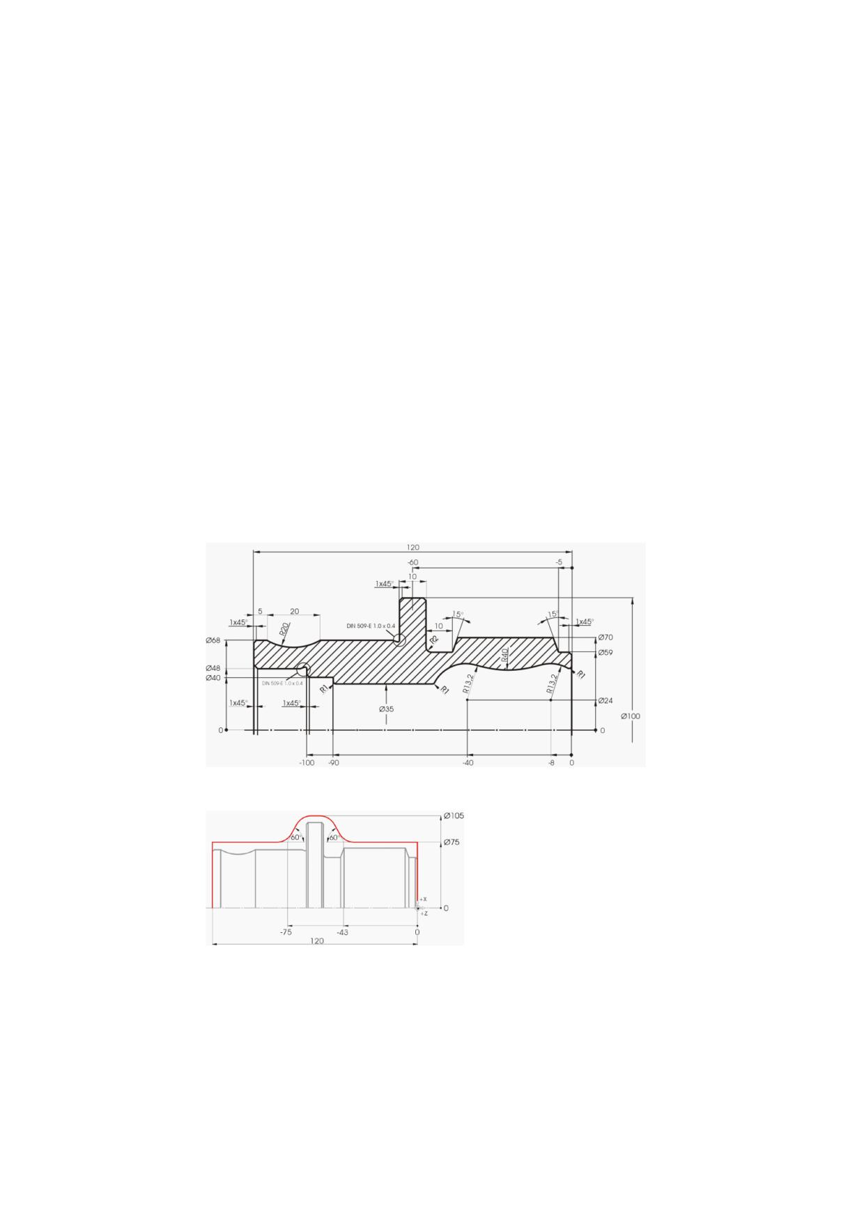
Figure 9-1
Workshop drawing - Example 4:
Figure 9-2
Blank contour
Turning made easy with ShopTurn
Training Documents, 09/2011, 6FC5095-0AB80-1BP1
147
Example 4: Hollow shaft
9.2 Creating the first workpiece side
All non-dimensioned radii R10.
Note
On account of improved clamping, side 1 is manufactured first.
9.2
Creating the first workpiece side
Creating a process plan
Since the workpiece is to be machined from two sides (and produced without
counterspindle), two process plans must be created.
Create the process plan for the left-hand side first ('HOLLOW_SHAFT_SIDE1')
Operating sequences
Create the program 'HOLLOW_SHAFT_SIDE1' without help.
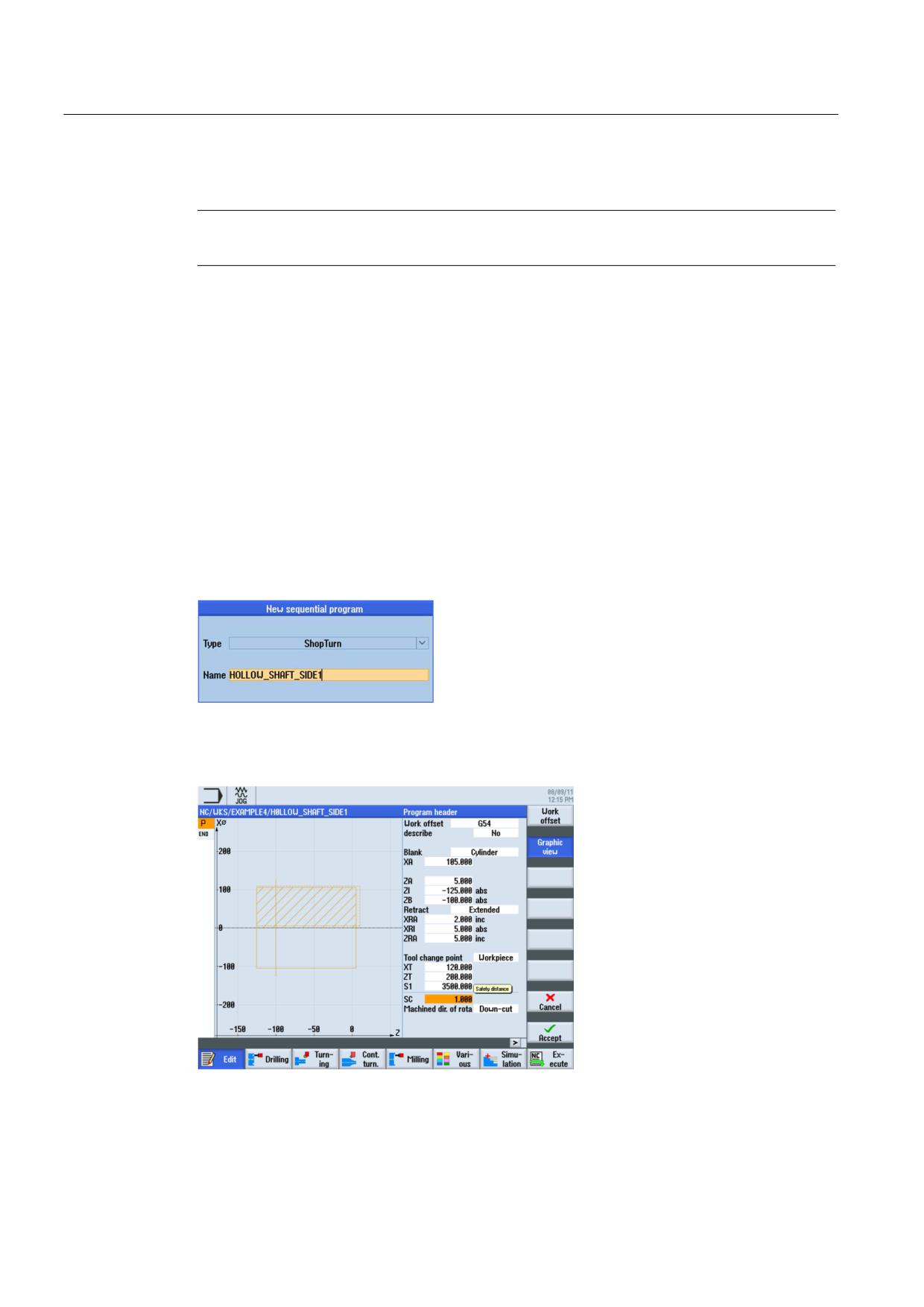
Figure 9-3
Creating a ShopTurn program
Enter the following data in the program header (see illustration).
Figure 9-4
Workpiece dimensions in the program header
Turning made easy with ShopTurn
148
Training Documents, 09/2011, 6FC5095-0AB80-1BP1
Example 4: Hollow shaft
9.2 Creating the first workpiece side
9.2.1
Face turning
Operating sequences
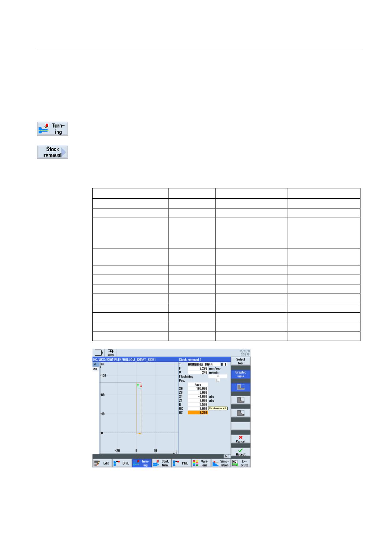
Proceed as follows to face turn the blank to Z0:
Select the Turning softkey.
Select the Stock removal softkey.
Select the ROUGHING_T80 A tool.
Enter the following values in the interactive screenform:
Field
Value
Selection via toggle key
Notes
F
0.2
V
240 m/min
X
Machining
Roughing
X
Since a large amount of
material (5mm) remains
on the front face, set the
machining to roughing.
Position
(see illustration
X
below)
Machining direction
Chart
X
X0
105
Z0
5
X1
-1.6 abs
X
Z1
0 abs
X
D
2.5
UX
0.0
UZ
0.2
Figure 9-5
Face turning the workpiece
Turning made easy with ShopTurn
Training Documents, 09/2011, 6FC5095-0AB80-1BP1
149
Example 4: Hollow shaft
9.2 Creating the first workpiece side
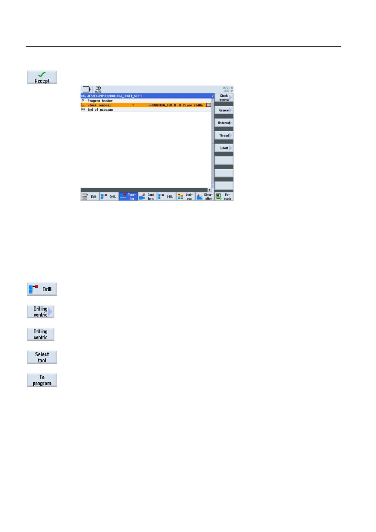
Accept the entered values. After acceptance, your work step program looks like this:
Figure 9-6
Process plan following face turning
9.2.2
Drilling
Operating sequences
Proceed as follows to drill the workpiece at the center.
Select the Drilling softkey.
Select the Drilling Centric softkey.
Select the Drilling Centric softkey.
Open the tool list and select DRILL_32.
Accept the tool into your program.
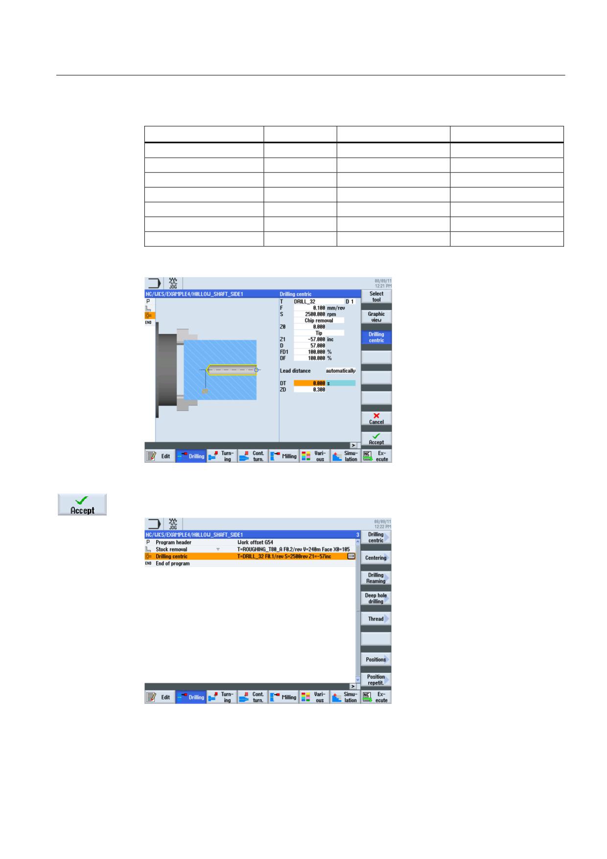
Enter the following values for the drill hole in the interactive screenform:
Turning made easy with ShopTurn
150
Training Documents, 09/2011, 6FC5095-0AB80-1BP1
Example 4: Hollow shaft
9.2 Creating the first workpiece side
Field
Value
Selection via toggle key
Notes
F
0.1 mm/rev
X
S
2500 rpm
X
Chip removal
X
Z0
0
Tip
X
Z1
-57 inc
X
D
57
Figure 9-7
Hole
"Apply" the set values. After acceptance, the list of work steps looks like this:
Figure 9-8
Process plan following drilling
Turning made easy with ShopTurn
Training Documents, 09/2011, 6FC5095-0AB80-1BP1
151
Example 4: Hollow shaft
9.2 Creating the first workpiece side
9.2.3
Blank contour
Operating sequences
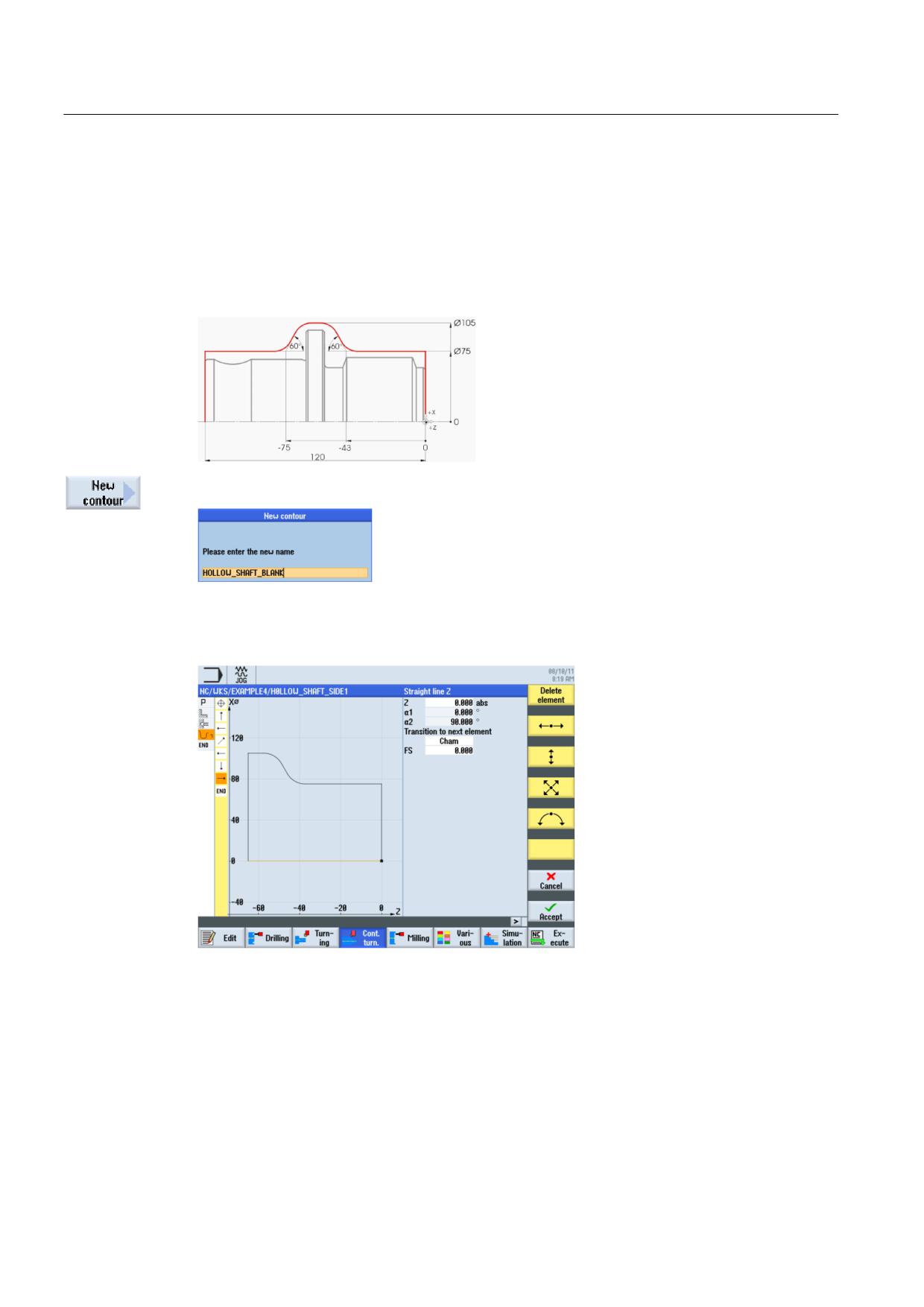
Enter the following blank contour without help. Since the workpiece is only machined on one
side for each process plan, the blank contour only needs to be constructed to Z-65.
Select the New contour softkey. Enter the name 'HOLLOW_SHAFT_BLANK' for the contour.
Figure 9-9
Creating the contour
Create the blank contour in the contour calculator (see illustration below).
Figure 9-10 Creating a blank contour
Turning made easy with ShopTurn
152
Training Documents, 09/2011, 6FC5095-0AB80-1BP1
Example 4: Hollow shaft
9.2 Creating the first workpiece side
9.2.4
Machined part contour of the first side, external
Operating sequences
Proceed as follows to enter the machined part contour:
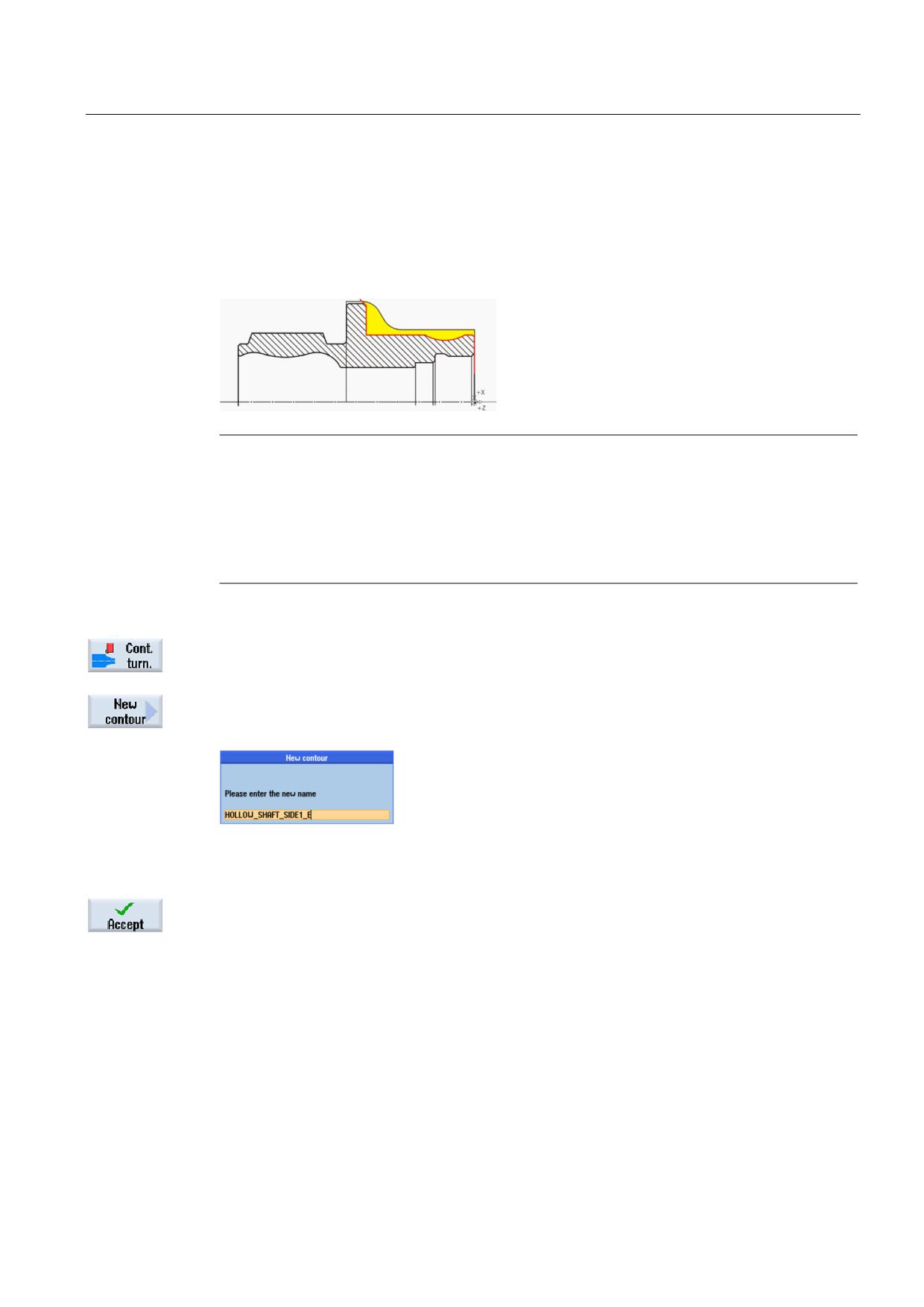
Note
The (red) contour of the machined part is intended not to correspond to the drawing. The
machined part contour serves as the roughing machining limit, but more importantly it
specifies the precise traversing path for finishing. Thus, the construction begins here at the
drill hole diameter. This ensures that the end face is finished cleanly. The contour end is an
extension of the chamfer extending outside the blank. The large diameter is produced only in
the second clamping.
Select the Contour turning softkey.
Select the New contour softkey. Enter the name 'HOLLOW_SHAFT_SIDE1_E' for the
contour.
Figure 9-11 Creating the contour
Confirm your input.
Turning made easy with ShopTurn
Training Documents, 09/2011, 6FC5095-0AB80-1BP1
153
Example 4: Hollow shaft
9.2 Creating the first workpiece side
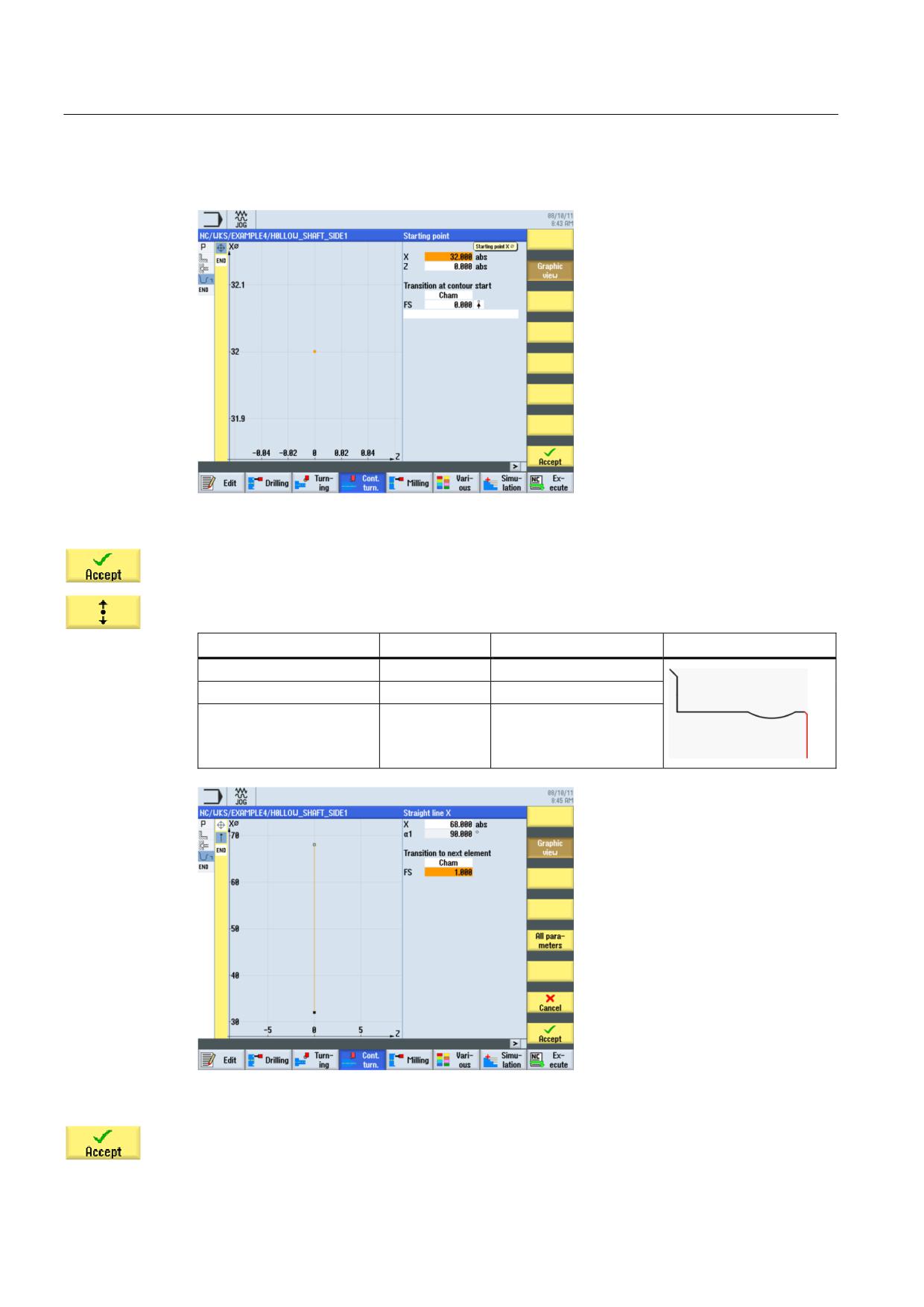
Set the starting point to X32/Z0.
Figure 9-12 Specifying the contour starting point
Confirm your input.
Enter the following values for the vertical straight line in the interactive screenform:
Field
Value
Selection via toggle key
Notes
X
68 abs
X
Transition to next element
Chamfer
X
F
1
Figure 9-13 Specifying the vertical straight line contour
Accept the entered values.
Turning made easy with ShopTurn
154
Training Documents, 09/2011, 6FC5095-0AB80-1BP1
Example 4: Hollow shaft
9.2 Creating the first workpiece side
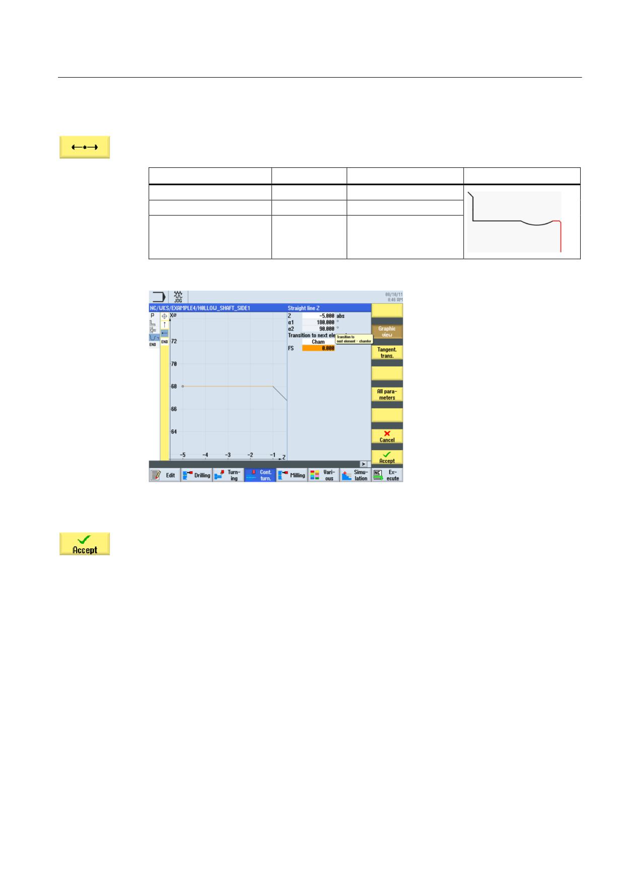
Enter the following values for the horizontal straight line in the interactive screenform:
Field
Value
Selection via toggle key
Notes
Z
-5 abs
X
Transition to next element
Chamfer
X
FS
0
Figure 9-14 Specifying the horizontal straight line contour
Accept the entered values.
Turning made easy with ShopTurn
Training Documents, 09/2011, 6FC5095-0AB80-1BP1
155
Example 4: Hollow shaft
9.2 Creating the first workpiece side
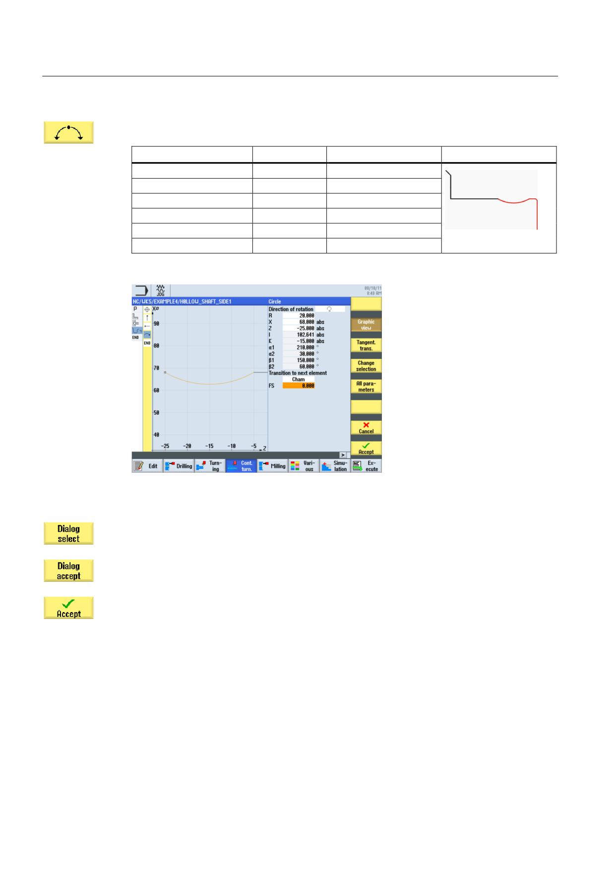
Enter the following values for the next section in the interactive screenform:
Field
Value
Selection via toggle key
Notes
Direction of rotation
Right
X
R
20
X
68 abs
X
Z
-25 abs
X
Transition to next element
Chamfer
X
FS
0
Figure 9-15 Specifying the arc contour
Select the desired construction.
Accept your selection.
Accept the contour section.
Turning made easy with ShopTurn
156
Training Documents, 09/2011, 6FC5095-0AB80-1BP1
Example 4: Hollow shaft
9.2 Creating the first workpiece side
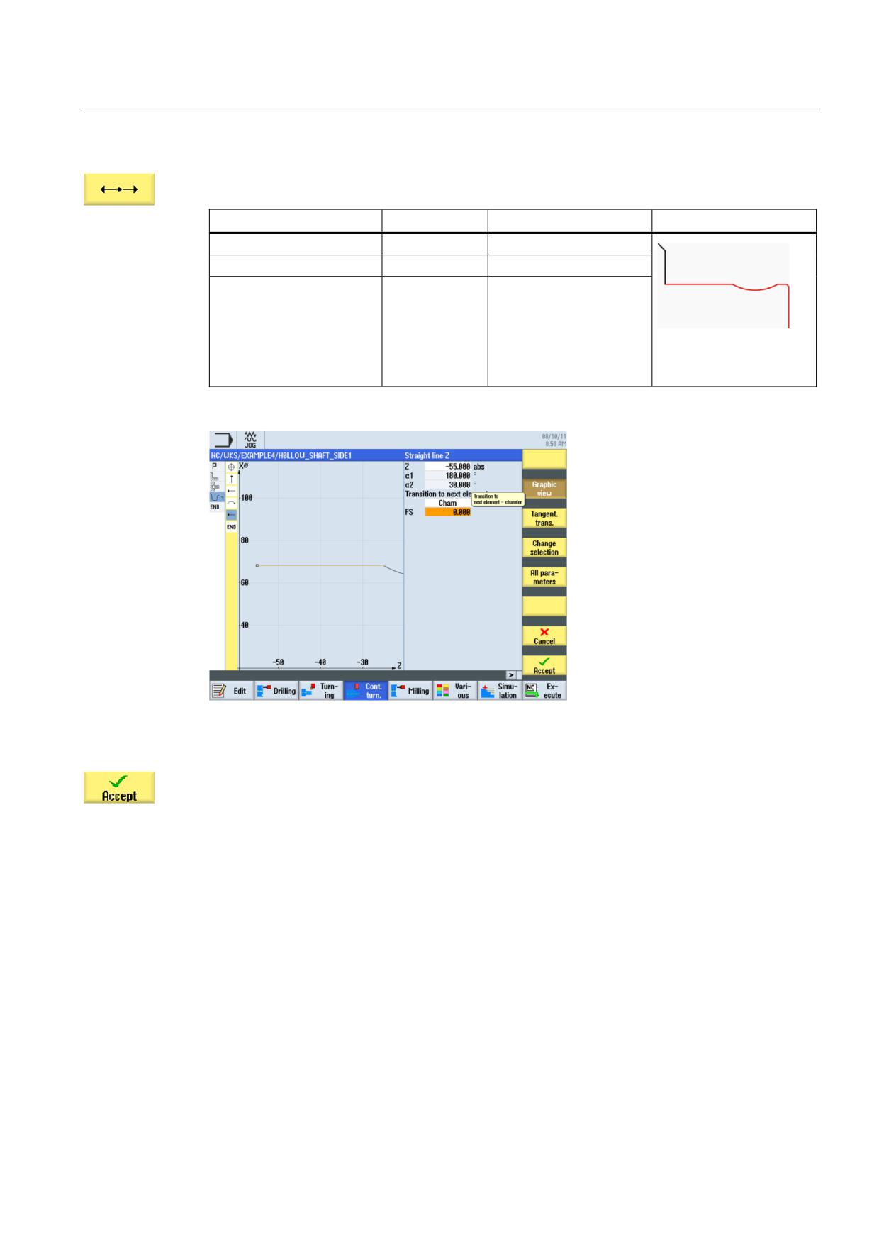
Enter the following values for the horizontal straight line in the interactive screenform:
Field
Value
Selection via toggle key
Notes
Z
-55 abs
X
Transition to next element
Chamfer
X
FS
0
The undercut is inserted
later as an individual
element.
Figure 9-16 Specifying the horizontal straight line contour
Accept the entered values.
Turning made easy with ShopTurn
Training Documents, 09/2011, 6FC5095-0AB80-1BP1
157
Example 4: Hollow shaft
9.2 Creating the first workpiece side
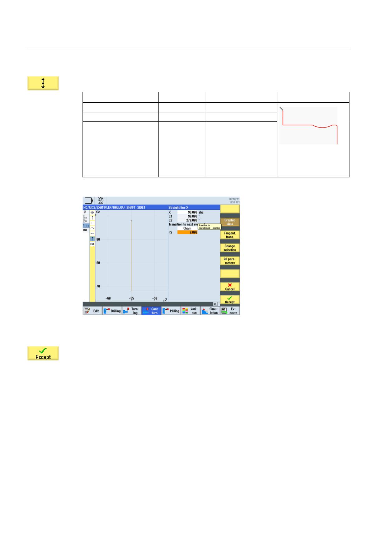
Enter the following values for the vertical straight line in the interactive screenform:
Field
Value
Selection via toggle key
Notes
X
98 abs
X
Transition to next element
Chamfer
X
FS
0
The inclined straight line
remains as chamfer after
the second side has been
machined.
Figure 9-17 Specifying the vertical straight line contour
Accept the entered values.
Turning made easy with ShopTurn
158
Training Documents, 09/2011, 6FC5095-0AB80-1BP1
Example 4: Hollow shaft
9.2 Creating the first workpiece side
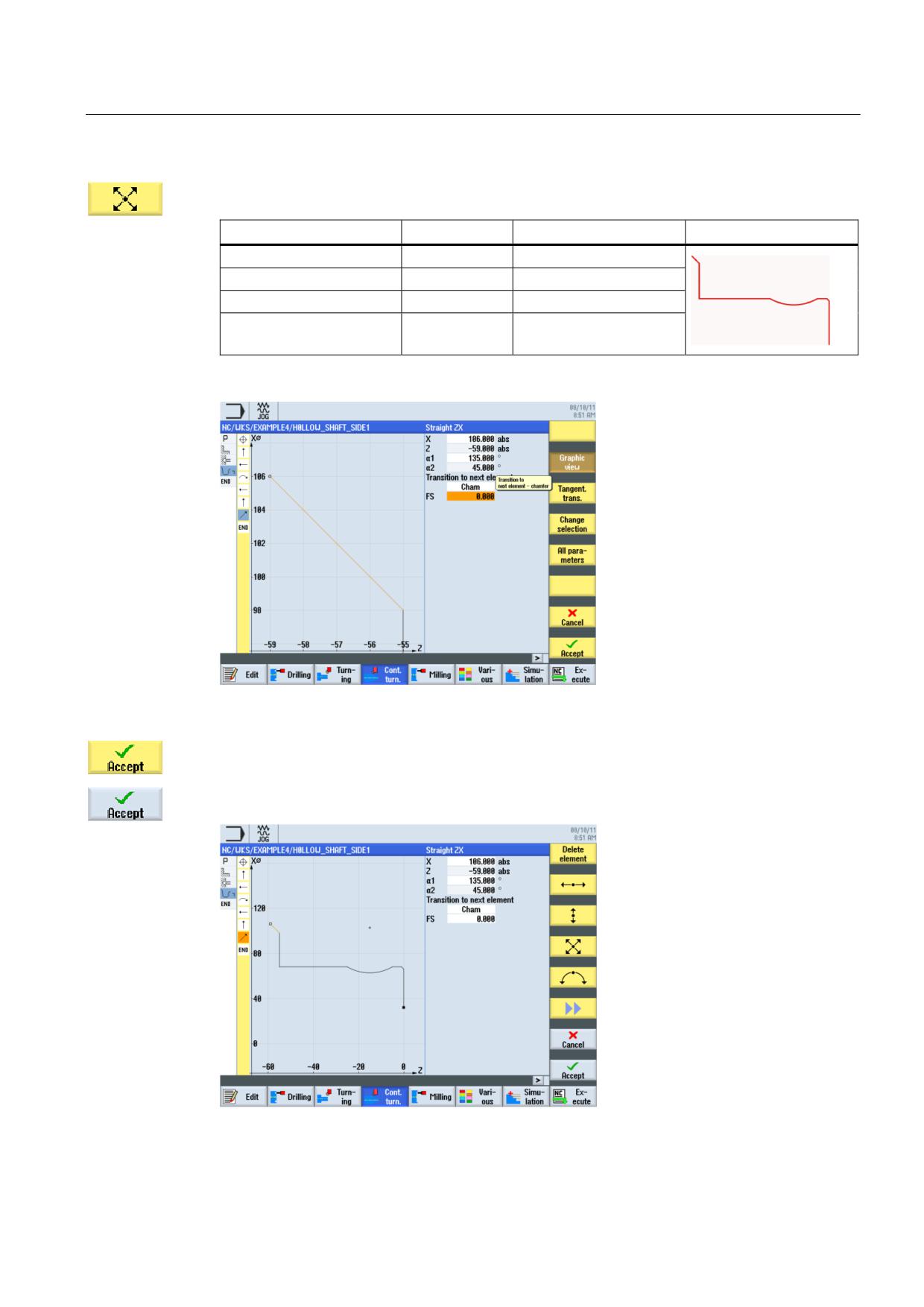
Enter the following values for the inclined straight line in the interactive screenform:
Field
Value
Selection via toggle key
Notes
X
106 abs
X
α1
135
X
Transition to next element
Chamfer
X
FS
0
Figure 9-18 Specifying the inclined straight line contour
Accept the entered values.
Accept the contour into your process plan.
Figure 9-19 Contour in the contour calculator
Turning made easy with ShopTurn
Training Documents, 09/2011, 6FC5095-0AB80-1BP1
159
Example 4: Hollow shaft
9.2 Creating the first workpiece side
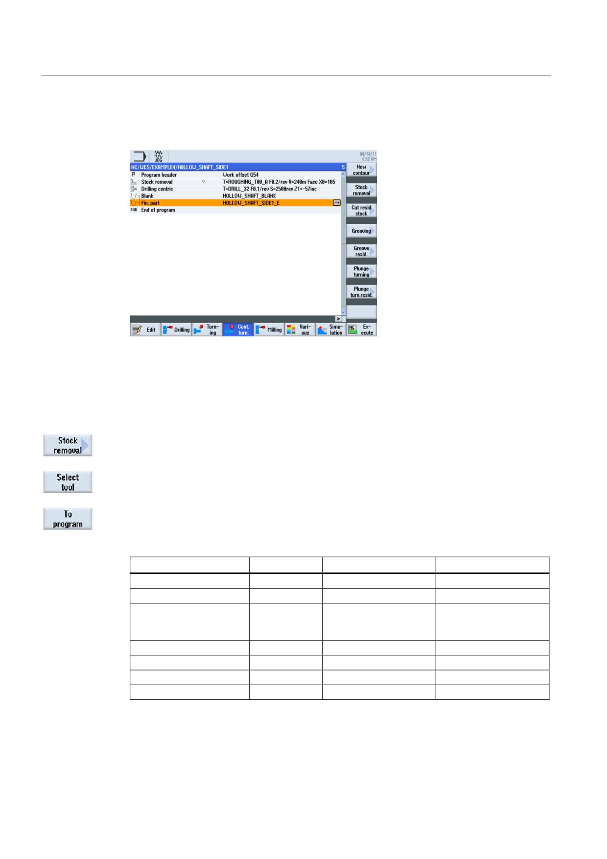
After acceptance, the process plan looks like this. Both contours are automatically linked
together.
Figure 9-20 Process plan following input of the contours
Stock removal, residual stock removal and finishing
In the following work step you will perform contour stock removal.
To this end, proceed as follows:
Select the Stock removal softkey.
Open the tool list and select the ROUGHING_T80 A tool.
Accept the tool into your program.
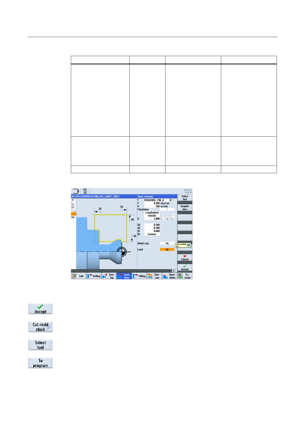
Enter the following values for roughing in the interactive screenform:
Field
Value
Selection via toggle key
Notes
F
0.3
V
260 m/min
X
Machining
longitudinal
X
external
X
roughing
X
D
2.0
UX
0.2
UZ
0.2
DI
0.0
Turning made easy with ShopTurn
160
Training Documents, 09/2011, 6FC5095-0AB80-1BP1
Example 4: Hollow shaft
9.2 Creating the first workpiece side
Field
Value
Selection via toggle key
Notes
BL
Contour
X
In the blank descriptions
you can choose between
the following settings:
Cylinder:
Blank = cylinder
Contour:
Blank = constructed
contour
Allowance:
Blank = constructed
contour with defined
allowance
Relief cuts
No
X
Insertion with the
roughing tool is not
recommended. Therefore,
switch the Relief cuts field
to No.
Set machining area limits
No
X
Figure 9-21 Roughing the contour
Accept the entered values.
Select the Residual stock removal softkey.
Open the tool list and select the FINISHING_T35 A tool.
Accept the tool into your program. Before finishing, the residual material is cut in the concave
fillet.
Turning made easy with ShopTurn
Training Documents, 09/2011, 6FC5095-0AB80-1BP1
161
Example 4: Hollow shaft
9.2 Creating the first workpiece side
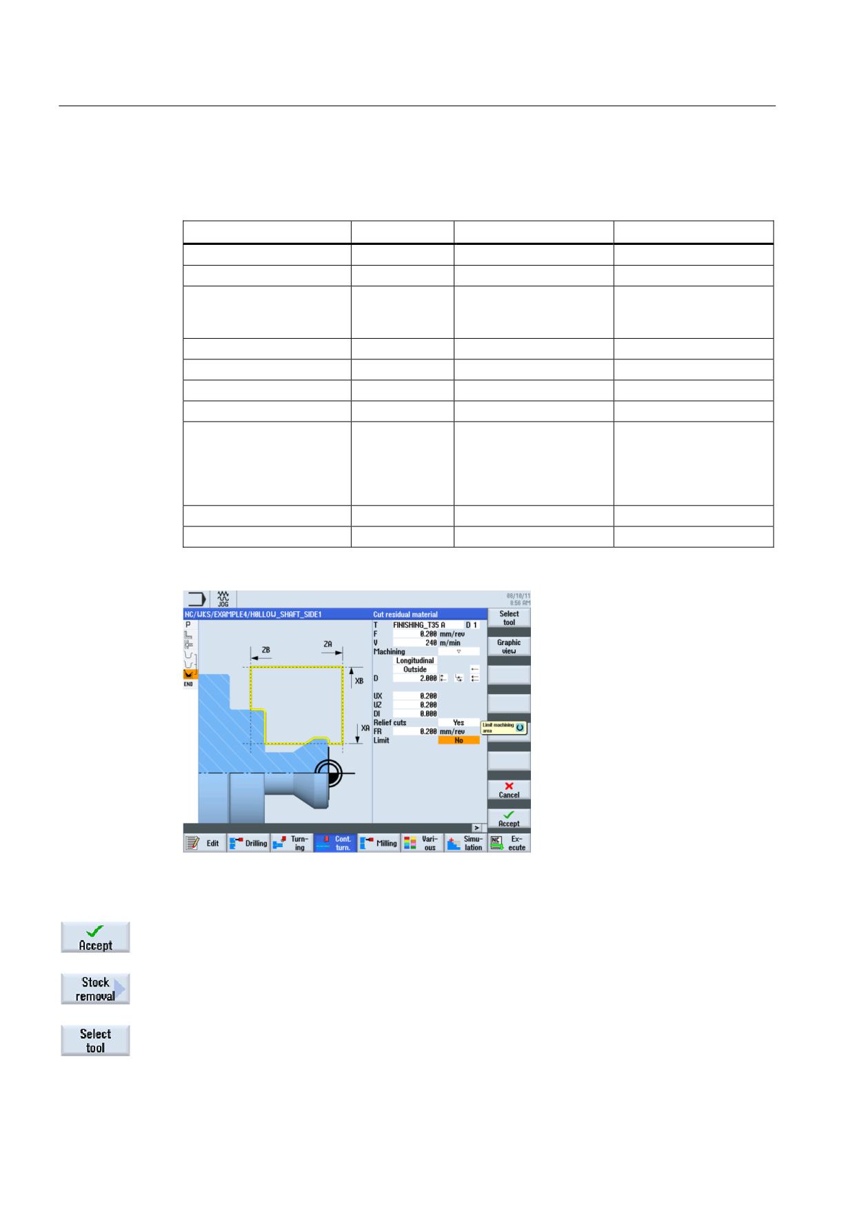
Enter the following values for stock removal of residual material in the interactive
screenform:
Field
Value
Selection via toggle key
Notes
F
0.2
V
240 m/min
X
Machining
longitudinal
X
external
X
roughing
X
D
2.0
UX
0.2
UZ
0.2
DI
0.0
Relief cuts
Yes
X
To ensure that the
concave fillet is taken into
consideration, the Relief
cuts field must be
switched to Yes.
FR
0.2
Set machining area limits
No
X
Figure 9-22 Stock removal of residual material contour
Accept the entered values.
Select the Stock removal softkey.
Open the tool list and select the FINISHING_T35 A tool.
Turning made easy with ShopTurn
162
Training Documents, 09/2011, 6FC5095-0AB80-1BP1
Example 4: Hollow shaft
9.2 Creating the first workpiece side
Accept the tool into your program.
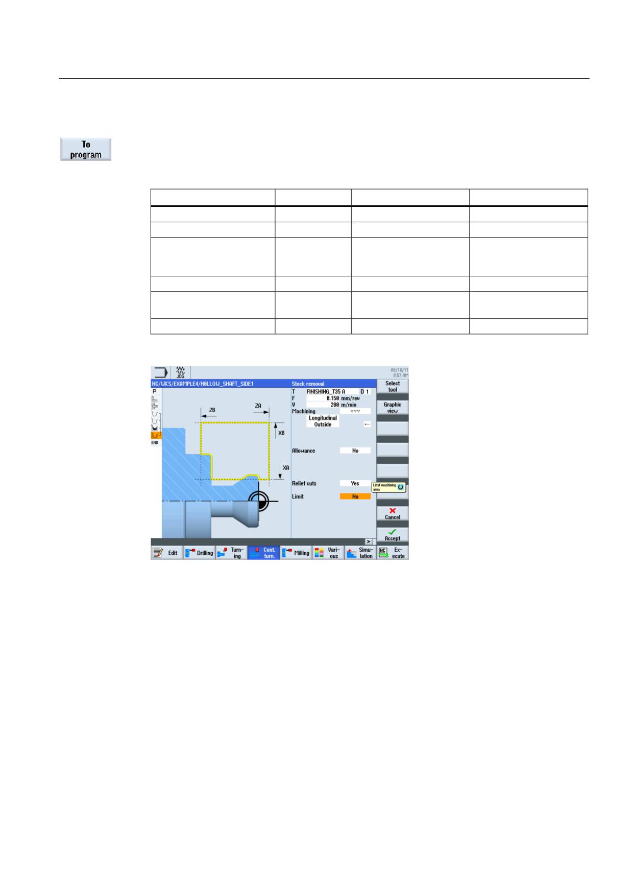
Enter the following values for finishing in the interactive screenform:
Field
Value
Selection via toggle key
Notes
F
0.15
V
280 m/min
X
Machining
longitudinal
X
external
X
finishing
X
Allowance
No
X
Relief cuts
Yes
X
Switch Relief cuts to Yes
here, too.
Set machining area limits
No
X
Figure 9-23 Finishing the contour
Turning made easy with ShopTurn
Training Documents, 09/2011, 6FC5095-0AB80-1BP1
163
Example 4: Hollow shaft
9.2 Creating the first workpiece side
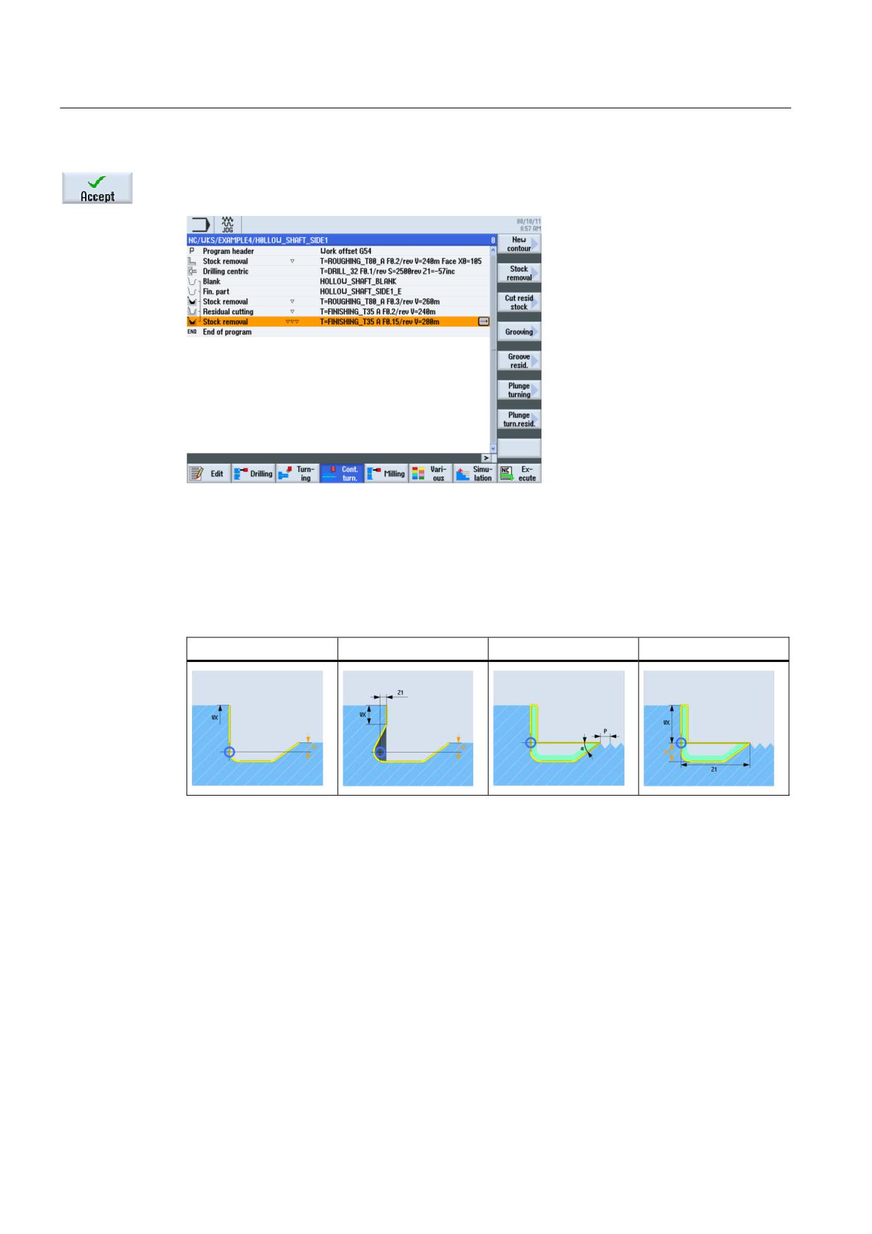
Accept the entered values. After acceptance, your work step program looks like this: The
contours are automatically linked to the stock removal work steps.
Figure 9-24 Process plan following stock removal of the contour
9.2.5
Undercut
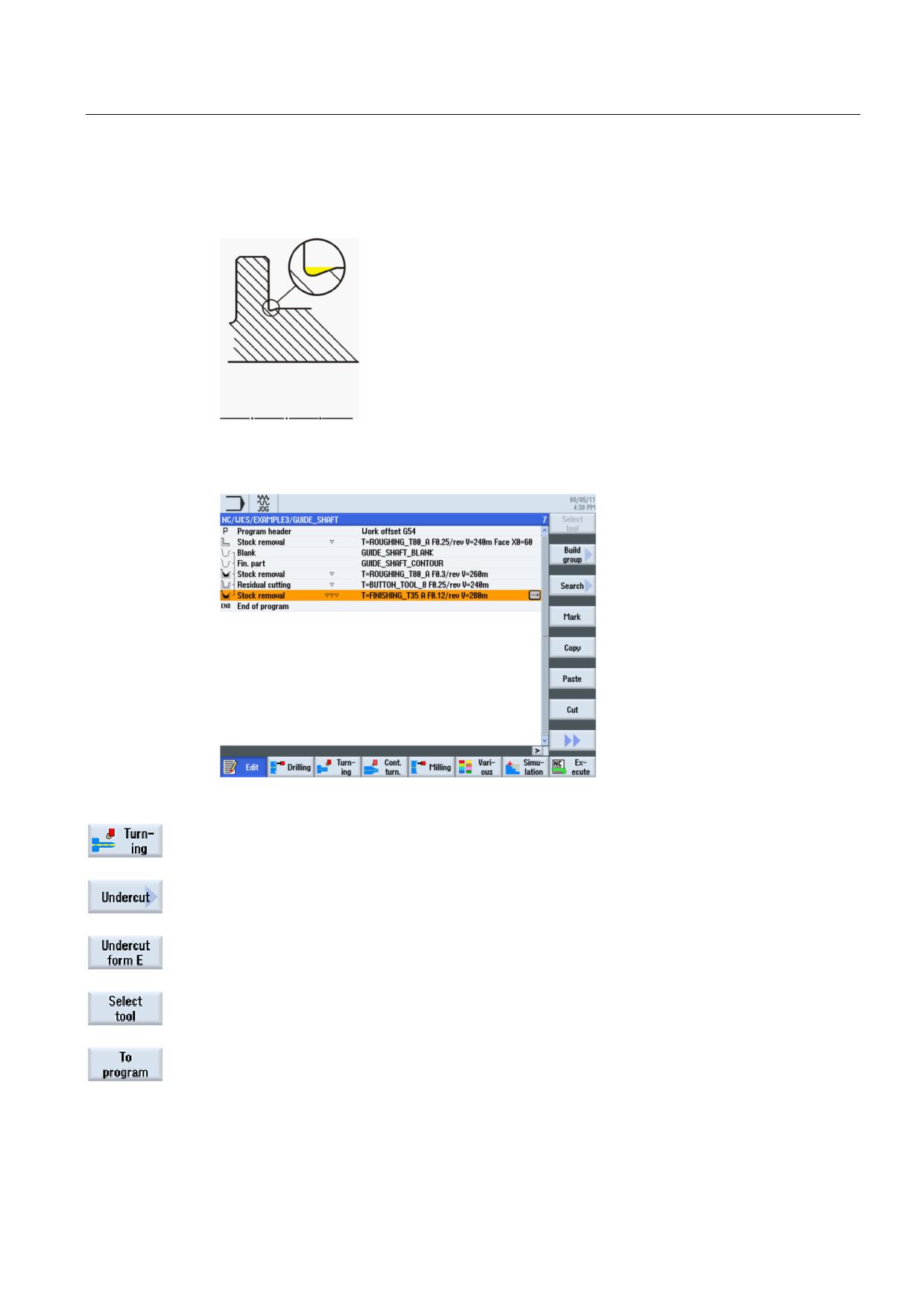
You can select from four different types of undercut:
Undercut form E
Undercut form F
Undercut DIN thread
Undercut thread
Turning made easy with ShopTurn
164
Training Documents, 09/2011, 6FC5095-0AB80-1BP1
Example 4: Hollow shaft
9.2 Creating the first workpiece side
Operating sequences
Proceed as follows to create an undercut.
After residual stock removal, the list of work steps looks like this:
Figure 9-25 Process plan following stock removal
Select the Turning softkey.
Select the Undercut softkey.
Select the Undercut form E softkey.
Open the tool list and select the FINISHING_T35 A tool.
Accept the tool into your program.
Turning made easy with ShopTurn
Training Documents, 09/2011, 6FC5095-0AB80-1BP1
165
Example 4: Hollow shaft
9.2 Creating the first workpiece side
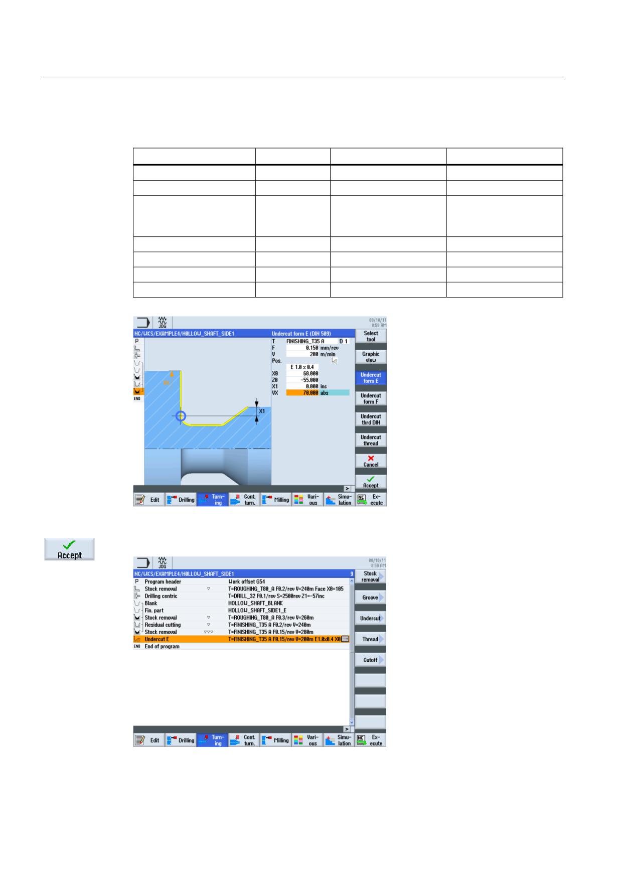
Enter the following values for the groove in the interactive screenform:
Field
Value
Selection via toggle key
Notes
F
0.15
V
200 m/min
X
Position
see illustration
X
below
E 1.0 x 0.4
X
X0
68
Z0
-55
X1
0 inc
X
VX
70 abs
X
Figure 9-26 Specifying the undercut
Accept the entered values. After acceptance, the list of work steps looks like this:
Figure 9-27 Process plan with undercut
Turning made easy with ShopTurn
166
Training Documents, 09/2011, 6FC5095-0AB80-1BP1
Example 4: Hollow shaft
9.2 Creating the first workpiece side
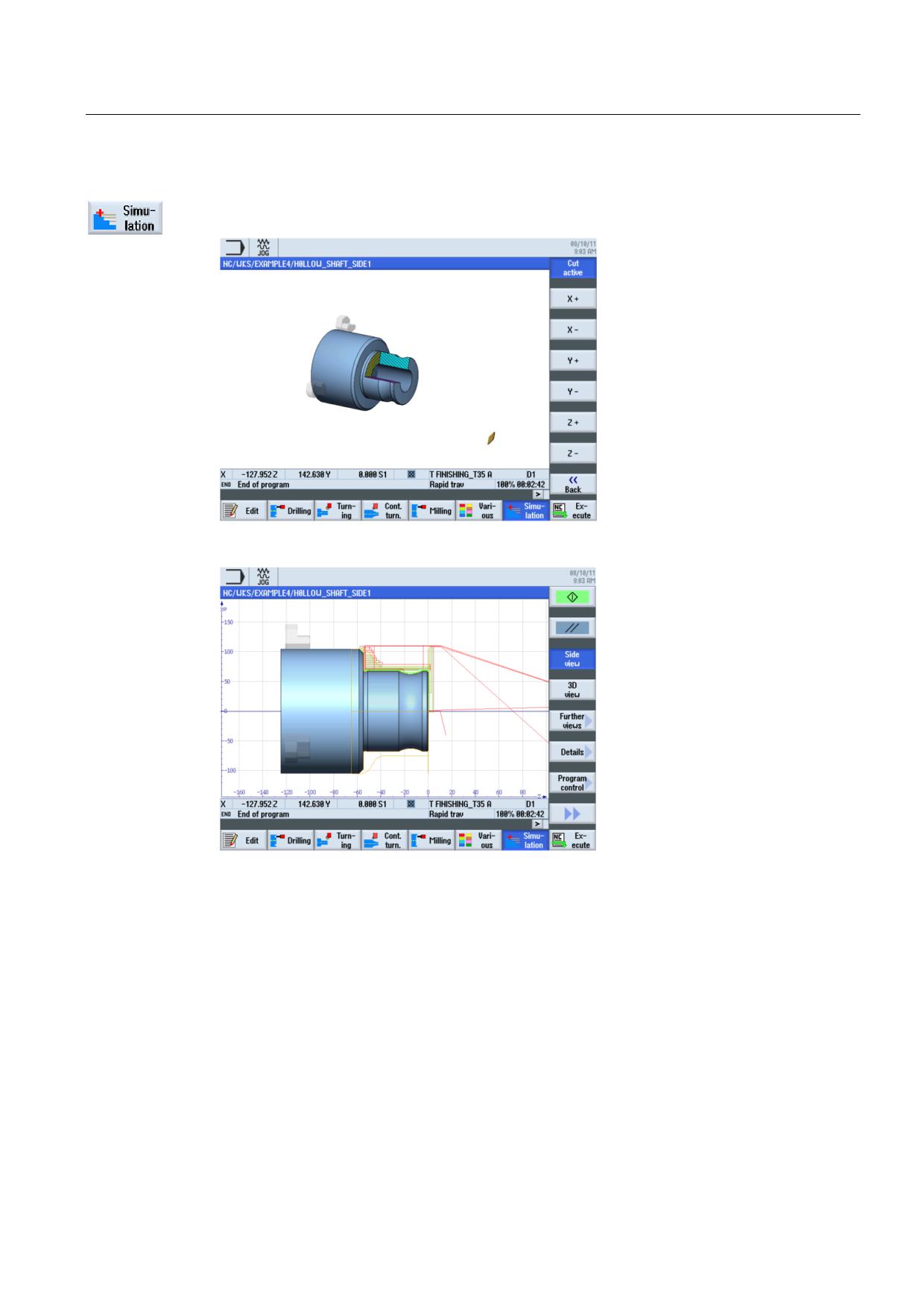
Start the simulation.
Figure 9-28 Simulation - Cut active
Figure 9-29 Simulation - Side view with display of the traversing paths
Turning made easy with ShopTurn
Training Documents, 09/2011, 6FC5095-0AB80-1BP1
167
Example 4: Hollow shaft
9.2 Creating the first workpiece side
9.2.6
Machined part contour of the first side, internal
Operating sequences
Proceed as follows to enter the machined part contour:
Select the Contour turning softkey.
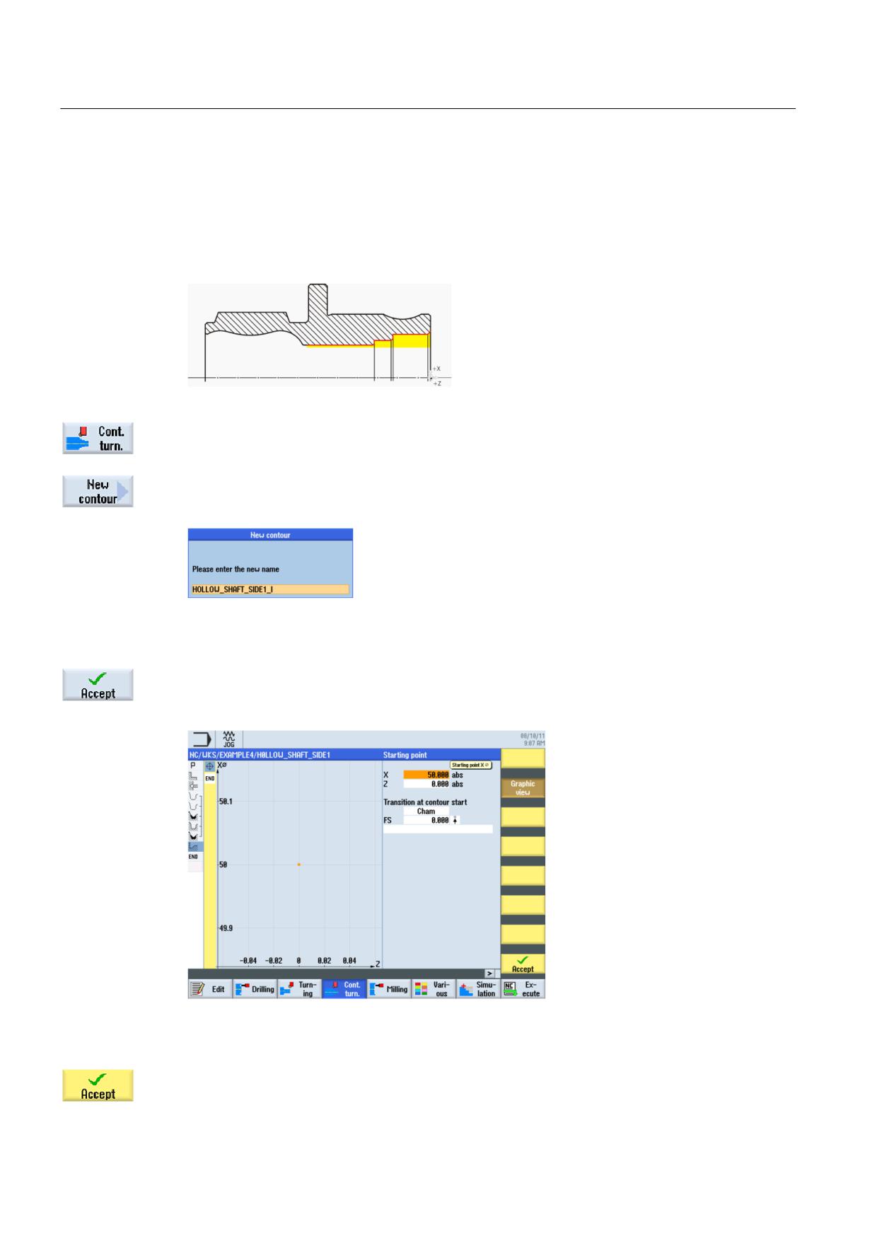
Select the New contour softkey. Enter the name 'HOLLOW_SHAFT_SIDE1_I' for the
contour.
Figure 9-30 Creating the contour
Confirm your input.
Set the starting point to X50/Z0.
Figure 9-31 Specifying the contour starting point
Confirm your input.
Turning made easy with ShopTurn
168
Training Documents, 09/2011, 6FC5095-0AB80-1BP1
Example 4: Hollow shaft
9.2 Creating the first workpiece side
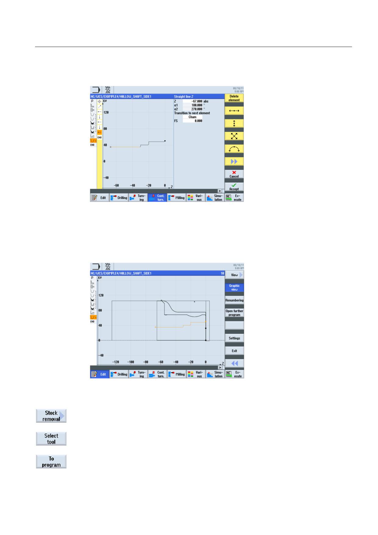
Create the contour without help (see illustration below).
Figure 9-32 Machined part contour of the first side, internal
Stock removal, residual stock removal and finishing
In the following work step you will perform contour stock removal. Enter the geometries into
your process plan as follows.
Figure 9-33 Broken-line graphics
Select the Stock removal softkey.
Open the tool list and select the ROUGHING_T80 I tool.
Accept the tool into your program.
Turning made easy with ShopTurn
Training Documents, 09/2011, 6FC5095-0AB80-1BP1
169
Example 4: Hollow shaft
9.2 Creating the first workpiece side
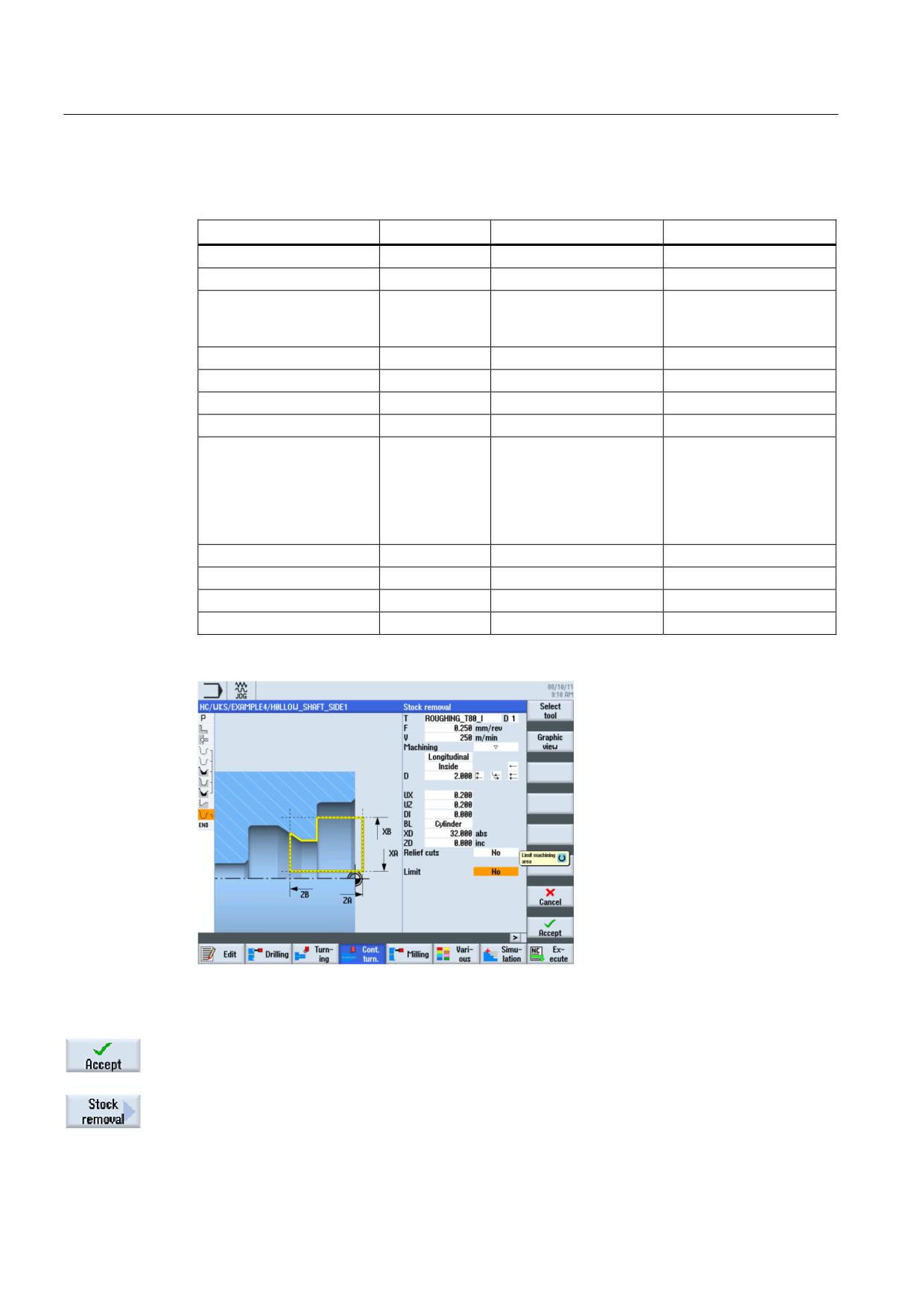
Enter the following values for roughing in the interactive screenform:
Field
Value
Selection via toggle key
Notes
F
0.25
V
250 m/min
X
Machining
longitudinal
X
You must switch the
internal
X
machining to Inside.
roughing
X
D
2.0
UX
0.2
UZ
0.2
DI
0.0
BL
Cylinder
X
Since drilling has already
taken place, you do not
need to take a blank
contour into consideration
for internal machining.
Switch to Cylinder.
XD
32 abs
X
ZD
0 inc
X
Relief cuts
No
X
Set machining area limits
No
X
Figure 9-34 Roughing the contour
Accept the entered values.
Select the Stock removal softkey.
Turning made easy with ShopTurn
170
Training Documents, 09/2011, 6FC5095-0AB80-1BP1
Example 4: Hollow shaft
9.2 Creating the first workpiece side
Open the tool list and select the FINISHING_T35 I tool.
Accept the tool into your program.
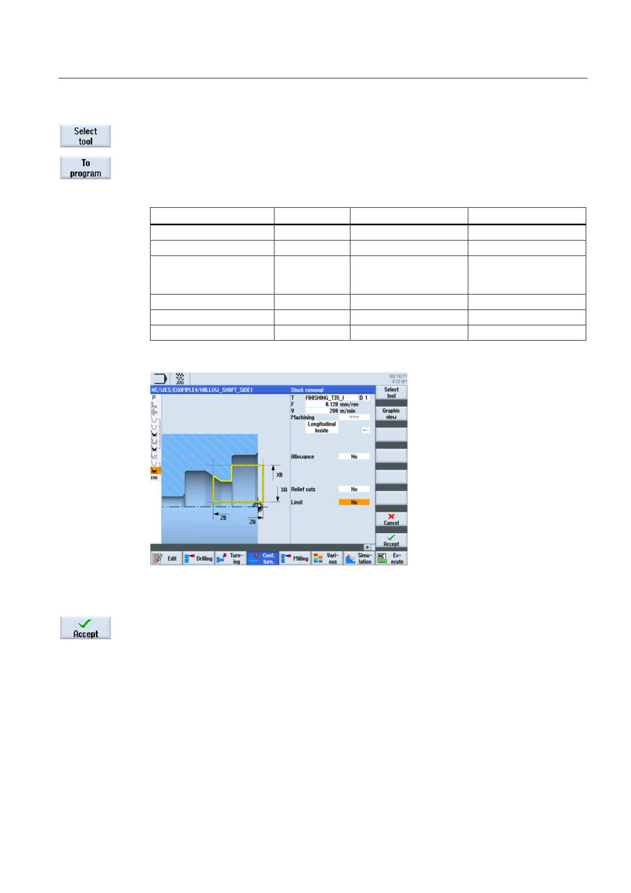
Enter the following values for finishing in the interactive screenform:
Field
Value
Selection via toggle key
Notes
F
0.12
V
280 m/min
X
Machining
longitudinal
X
internal
X
finishing
X
Allowance
No
X
Relief cuts
No
X
Set machining area limits
No
X
Figure 9-35 Finishing the contour
Accept the entered values.
Turning made easy with ShopTurn
Training Documents, 09/2011, 6FC5095-0AB80-1BP1
171
Example 4: Hollow shaft
9.2 Creating the first workpiece side
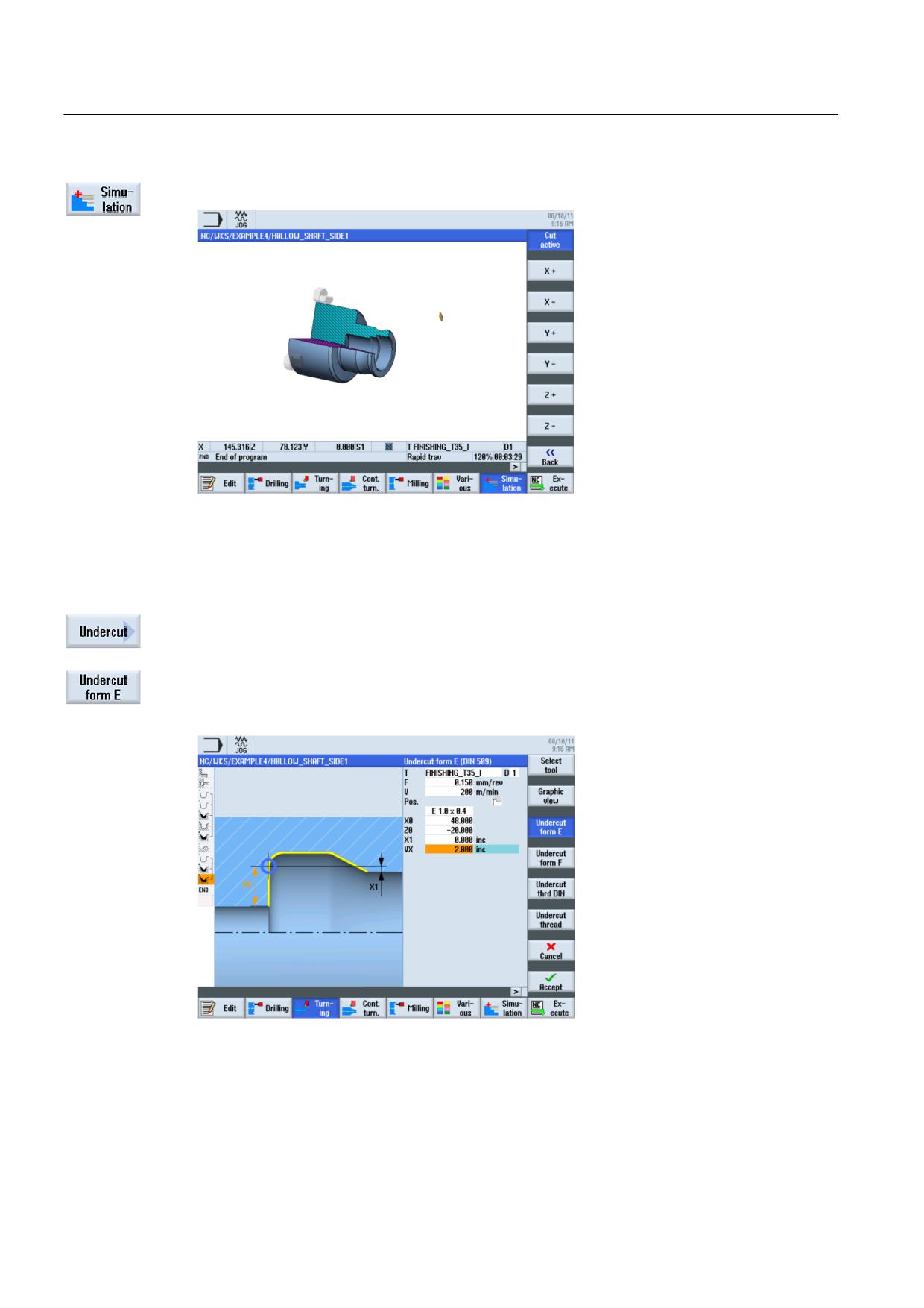
Start the simulation to perform checks.
Figure 9-36 Simulation - Cut active
Undercut
Proceed as follows to create an undercut:
Select the Undercut softkey.
Select the Undercut form E softkey.
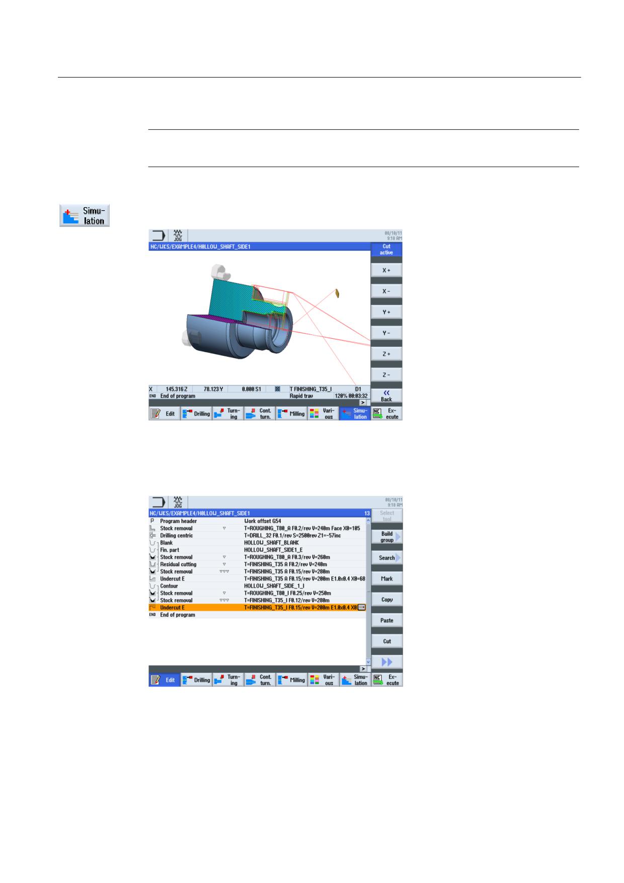
Create the undercut (see illustration below).
Figure 9-37 Creating an undercut
Turning made easy with ShopTurn
172
Training Documents, 09/2011, 6FC5095-0AB80-1BP1
Example 4: Hollow shaft
9.2 Creating the first workpiece side
Note
Make sure that the undercut is in the correct position.
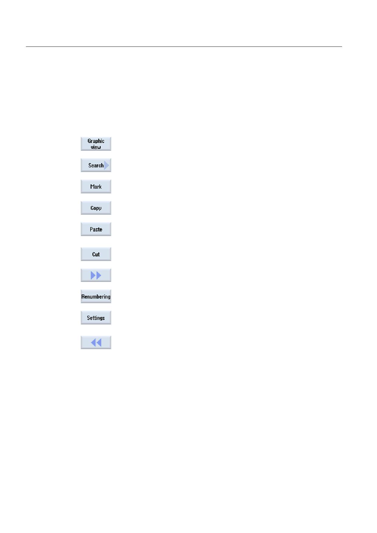
Start the simulation.
Figure 9-38 Undercut simulation (with display of the traversing paths)
The process plan for the first side of the workpiece looks like this.
Figure 9-39 Process plan with undercut
Turning made easy with ShopTurn
Training Documents, 09/2011, 6FC5095-0AB80-1BP1
173
Example 4: Hollow shaft
9.2 Creating the first workpiece side
9.2.7
The work step editor
Functions of the work step editor
The following information provides you with an overview of the functions of the work step
editor.
Use this softkey to switch to the broken-line graphics.
Use this softkey to search for texts in the program.
Use this softkey to select several work steps for further processing (e.g.,
"Copy" or "Cut").
Use this softkey to copy work steps to the clipboard.
Use this softkey to paste work steps from the clipboard to the process
plan. The copied step is always inserted after the currently highlighted
step.
Use this softkey to copy work steps to the clipboard; at the same time, it
is deleted at its origin. This softkey can also be used for "pure" deletion.
Use this softkey to switch to the extended menu.
Use this softkey to renumber the work steps.
Use this softkey to open the "Settings" dialog. Here you can specify, e.g.
automatic numbering or whether you wish the end of the block to be
represented as a symbol.
Use this softkey to return to the previous menu.
Turning made easy with ShopTurn
174
Training Documents, 09/2011, 6FC5095-0AB80-1BP1
Example 4: Hollow shaft
9.2 Creating the first workpiece side
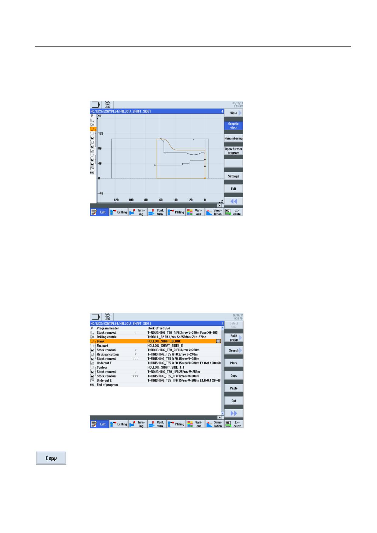
You will need some of these functions in order to reuse the blank contour of the first side in
the process plan for the second side of the workpiece. The blank contour will be copied to
the clipboard and pasted into the process plan for the second side.
Figure 9-40 Blank contour
9.2.8
Copying the contour
Operating sequence
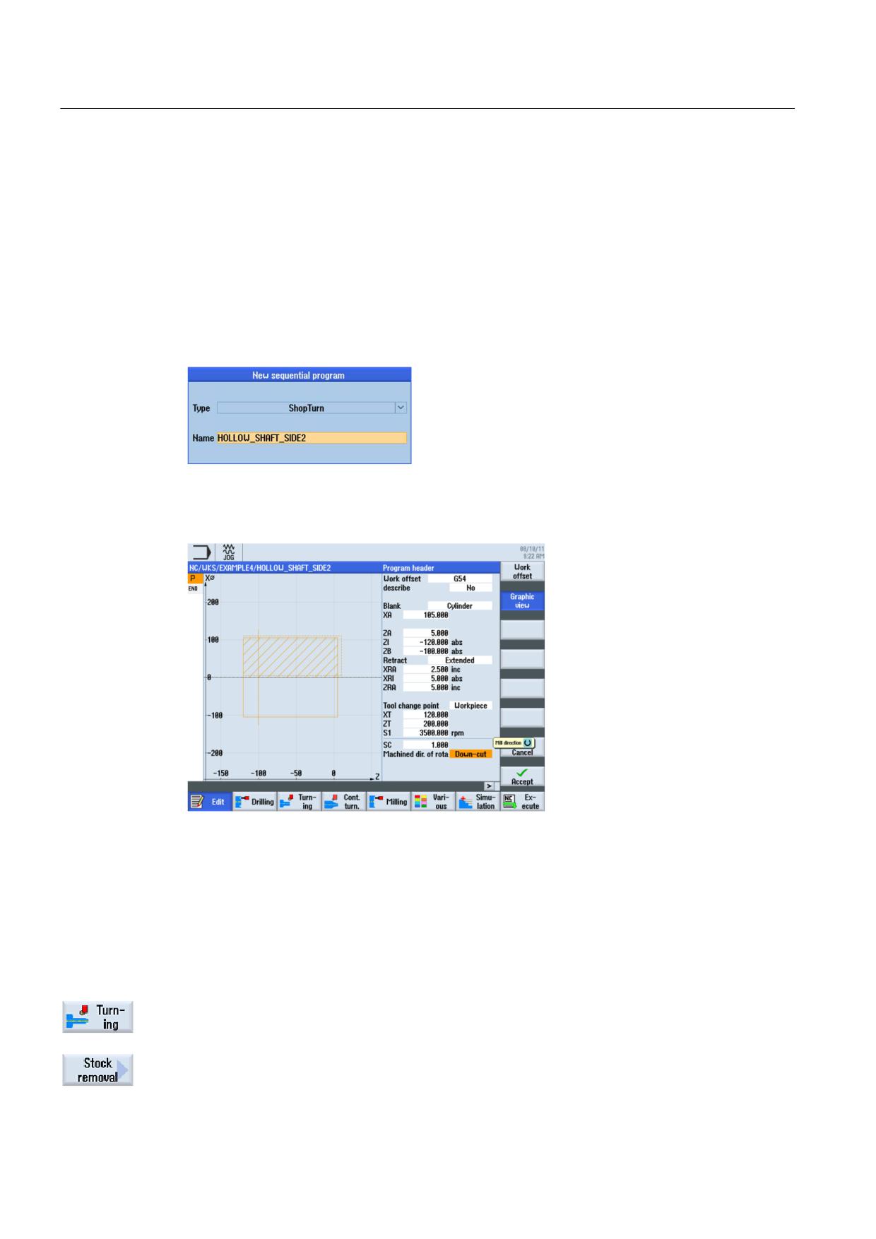
Proceed as follows to copy the blank contour to the clipboard:
Navigate to the 'HOLLOW_SHAFT_BLANK' contour.
Figure 9-41 Copying the contour to the clipboard.
Copy the blank contour to the clipboard. The contour remains on the clipboard until you copy
another work step to the clipboard or shut down the control system.
Turning made easy with ShopTurn
Training Documents, 09/2011, 6FC5095-0AB80-1BP1
175
Example 4: Hollow shaft
9.3 Creating the second workpiece side
9.3
Creating the second workpiece side
Creating a process plan
Proceed as follows to create a process plan for the second side of the workpiece.
Operating sequences
Create the program 'HOLLOW_SHAFT_SIDE2' without help.
Figure 9-42 Creating a ShopTurn program
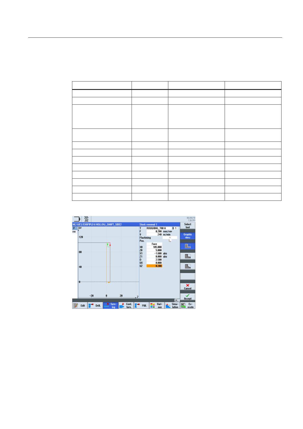
Enter the following data in the program header (see illustration).
Figure 9-43 Workpiece dimensions in the program header
9.3.1
Face turning
Operating sequences
Proceed as follows to face turn the blank to X-1.6 and Z0:
Select the Turning softkey.
Select the Stock removal softkey.
Turning made easy with ShopTurn
176
Training Documents, 09/2011, 6FC5095-0AB80-1BP1
Example 4: Hollow shaft
9.3 Creating the second workpiece side
Select the ROUGHING_T80 A tool.
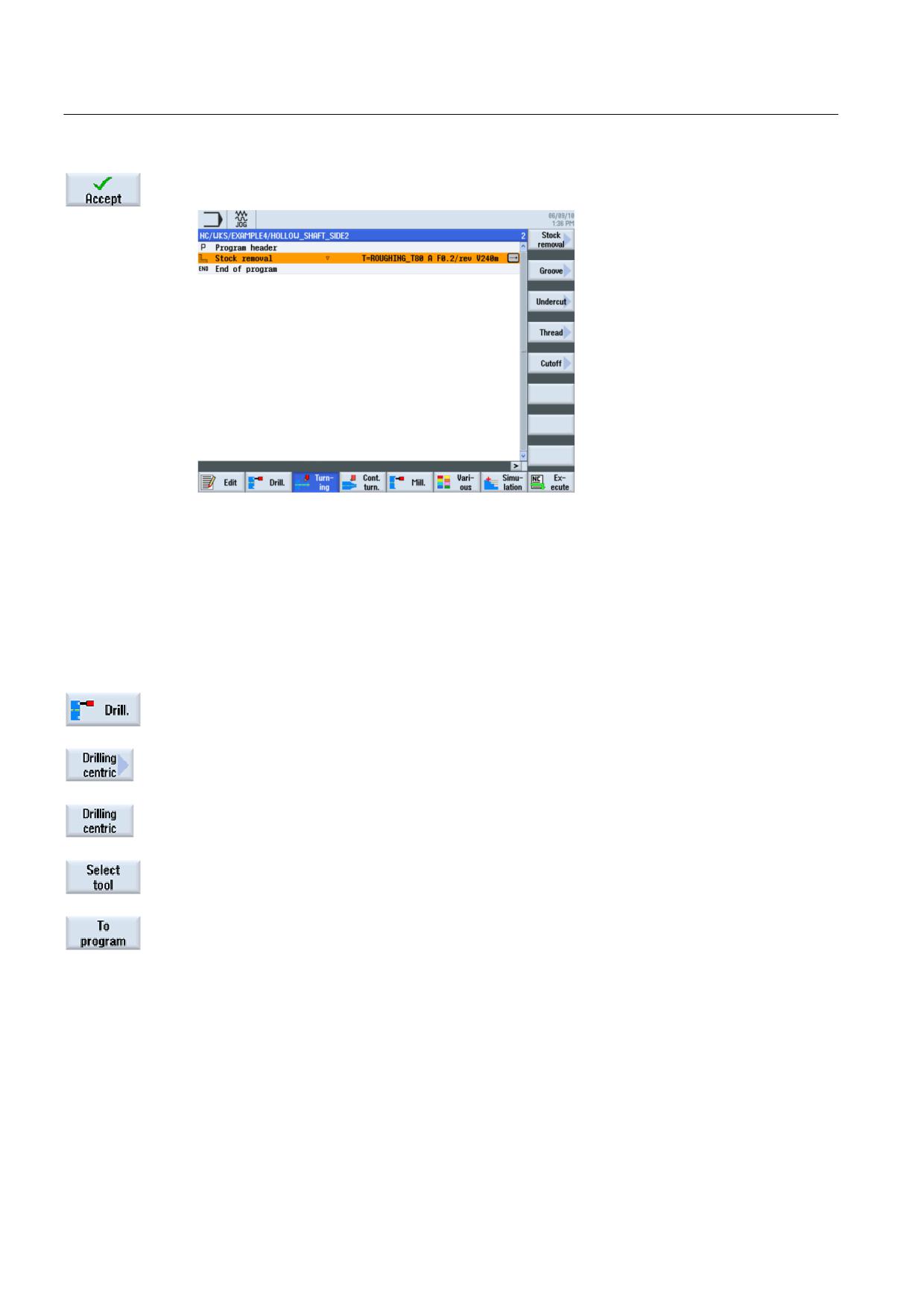
Enter the following values in the interactive screenform:
Field
Value
Selection via toggle key
Notes
F
0.2
V
240 m/min
X
Machining
Roughing
X
Since a large amount of
material (5mm) remains
on the front face, set the
machining to roughing.
Position
(see illustration
X
below)
Machining direction
Chart
X
X0
105
Z0
5
X1
-1.6 abs
X
Z1
0 abs
X
D
2.5
UX
0.0
UZ
0.2
Figure 9-44 Face turning the workpiece
Turning made easy with ShopTurn
Training Documents, 09/2011, 6FC5095-0AB80-1BP1
177
Example 4: Hollow shaft
9.3 Creating the second workpiece side
Accept the entered values. After acceptance, your work step program looks like this:
Figure 9-45 Process plan following face turning
9.3.2
Drilling
Operating sequences
Proceed as follows to drill the workpiece at the center.
Select the Drilling softkey.
Select the Drilling Centric softkey.
Select the Drilling Centric softkey.
Open the tool list and select DRILL_32.
Accept the tool into your program.
Turning made easy with ShopTurn
178
Training Documents, 09/2011, 6FC5095-0AB80-1BP1
Example 4: Hollow shaft
9.3 Creating the second workpiece side
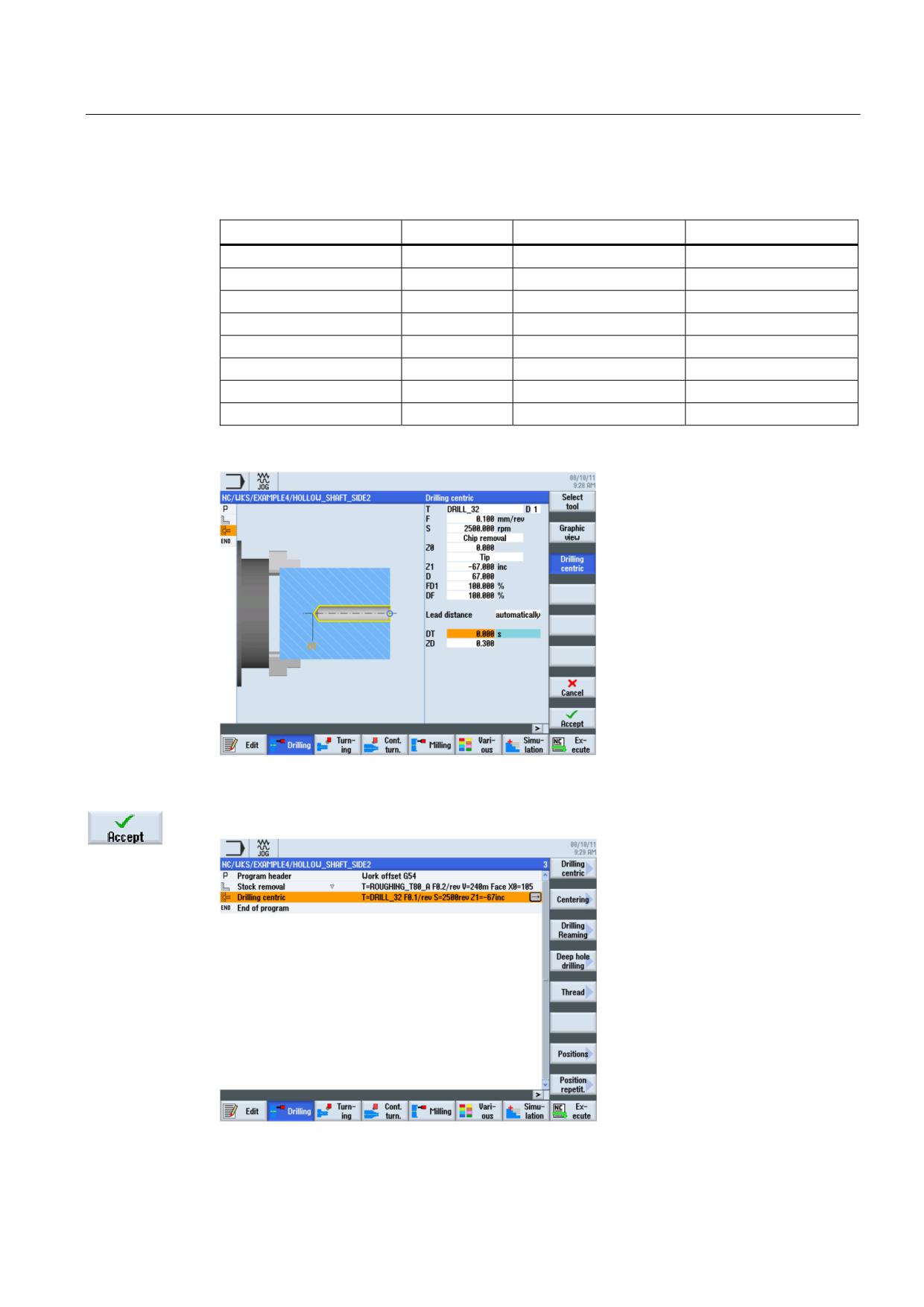
Enter the following values for the drill hole in the interactive screenform:
Field
Value
Selection via toggle key
Notes
F
0.1 mm/rev
X
S
2500 rpm
X
Chip removal
X
Z0
0
Tip
Z1
-67 abs
X
D
67
DT
0
X
Figure 9-46 Hole
"Apply" the set values. After acceptance, the list of work steps looks like this:
Figure 9-47 Process plan following input of the drilling position
Turning made easy with ShopTurn
Training Documents, 09/2011, 6FC5095-0AB80-1BP1
179
Example 4: Hollow shaft
9.3 Creating the second workpiece side
9.3.3
Specifying a blank contour
Operating sequences
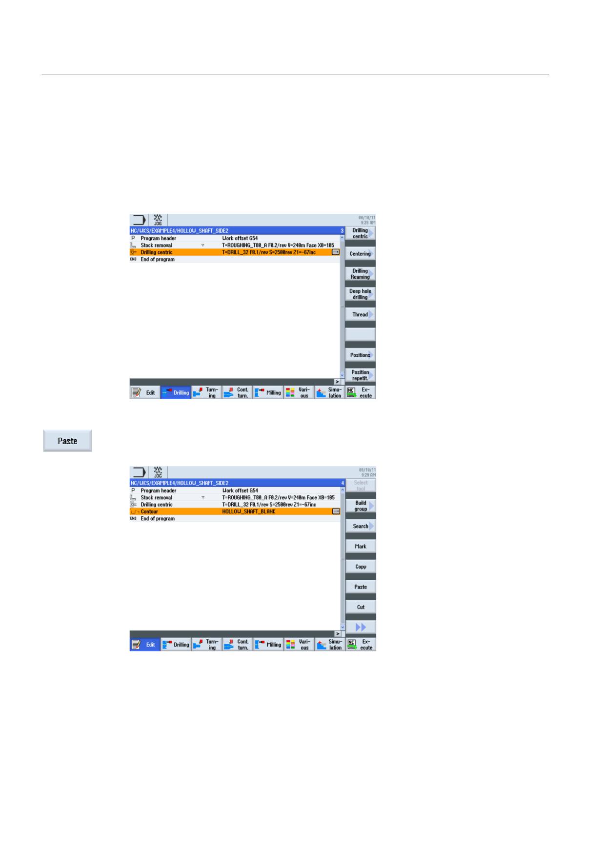
Proceed as follows to paste the blank contour from the clipboard into your process plan:
First, navigate in the process plan to the most recently entered work step (see illustration).
Figure 9-48 Position for inserting the blank contour
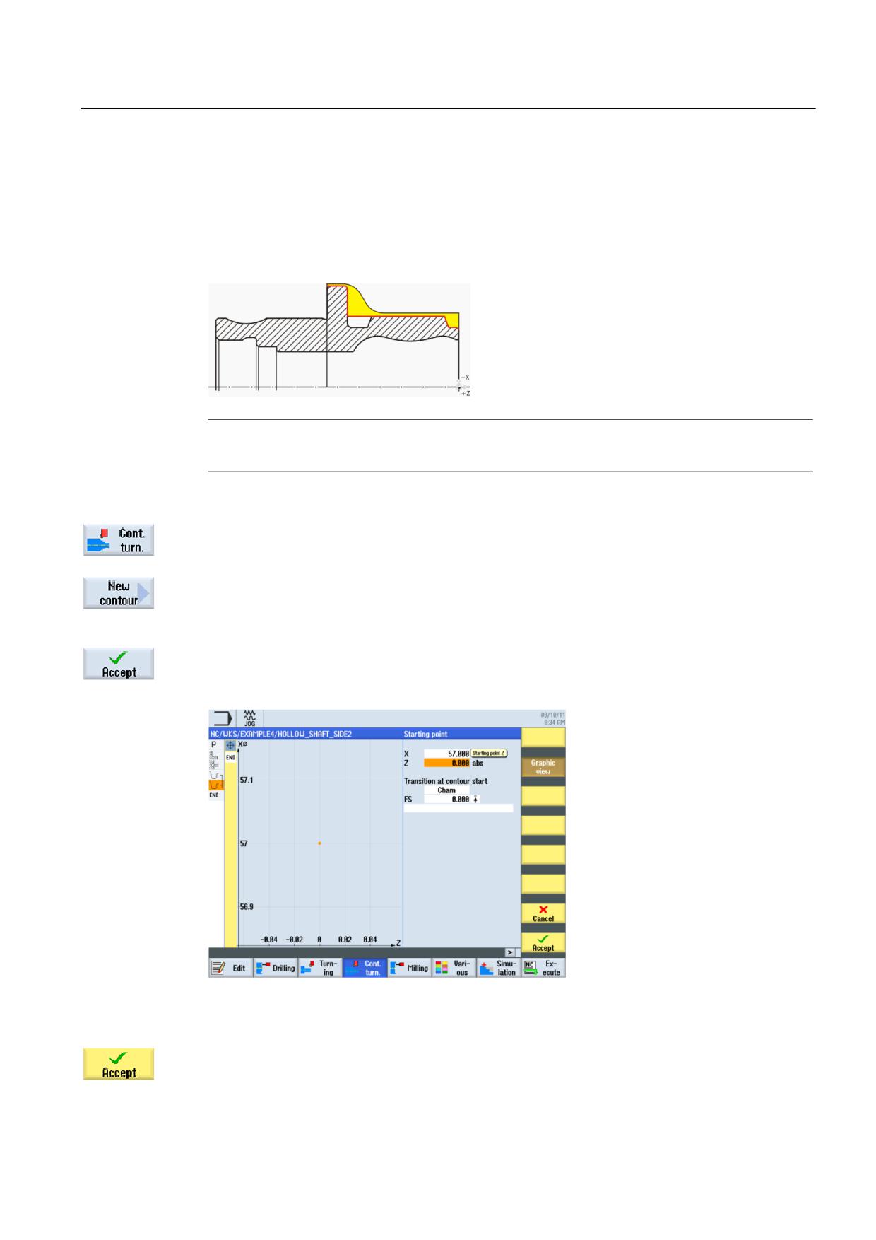
Paste the blank contour from the clipboard. After pasting the contour, your process plan
should look like this.
Figure 9-49 Pasting the contour
Turning made easy with ShopTurn
180
Training Documents, 09/2011, 6FC5095-0AB80-1BP1
Example 4: Hollow shaft
9.3 Creating the second workpiece side
9.3.4
Machined part contour of the second side, external
Operating sequences
Proceed as follows to enter the machined part contour:
Note
The asymmetrical groove is produced later.
Select the Contour turning softkey.
Select the New contour softkey. Enter the name 'HOLLOW_SHAFT_SIDE2_E' for the
contour.
"Apply" your input.
Set the starting point to X57/Z0.
Figure 9-50 Specifying the contour starting point
"Apply" your input.
Turning made easy with ShopTurn
Training Documents, 09/2011, 6FC5095-0AB80-1BP1
181
Example 4: Hollow shaft
9.3 Creating the second workpiece side
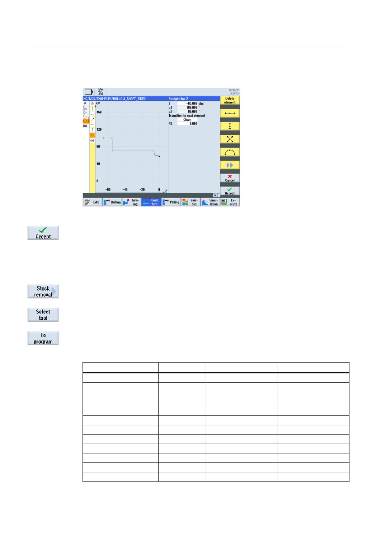
Create the contour up to the end point to Z-65 and X100 without help (see illustration below).
Figure 9-51 Contour in the contour calculator
Accept the contour into your process plan.
Stock removal and finishing
In the following work step you will perform contour stock removal.
To this end, proceed as follows:
Select the Stock removal softkey.
Open the tool list and select the ROUGHING_T80 A tool.
Accept the tool into your program.
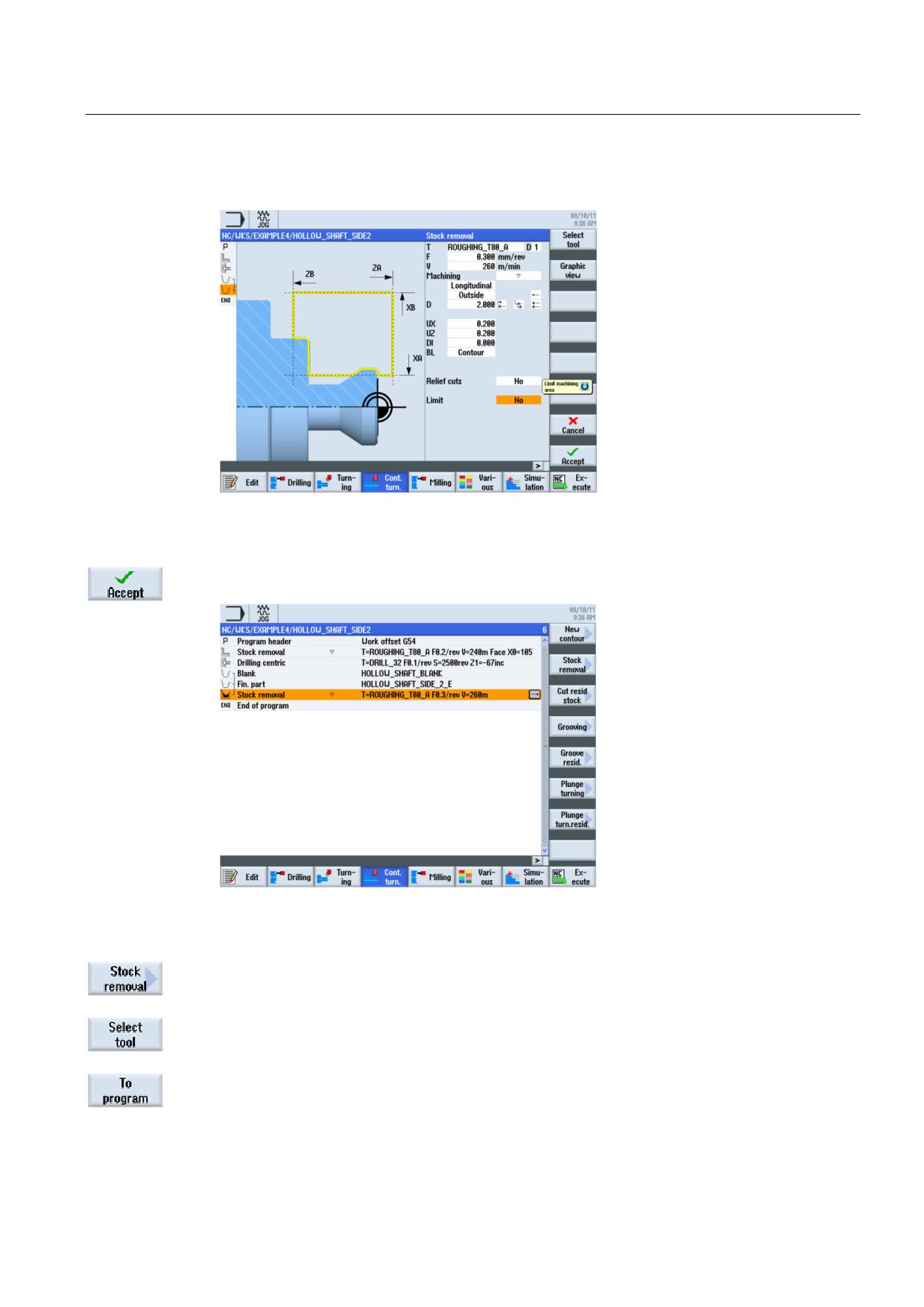
Enter the following values for roughing in the interactive screenform:
Field
Value
Selection via toggle key
Notes
F
0.3
V
260 m/min
X
Machining
longitudinal
X
external
X
roughing
X
D
2.0
UX
0.2
UZ
0.2
DI
0.0
BL
Contour
X
Relief cuts
No
X
Set machining area limits
No
X
Turning made easy with ShopTurn
182
Training Documents, 09/2011, 6FC5095-0AB80-1BP1
Example 4: Hollow shaft
9.3 Creating the second workpiece side
Figure 9-52 Roughing the contour
"Apply" the set values. After acceptance, your work step program looks like this:
Figure 9-53 Process plan following roughing
Select the Stock removal softkey.
Open the tool list and select the FINISHING_T35 A tool.
Accept the tool into your program.
Turning made easy with ShopTurn
Training Documents, 09/2011, 6FC5095-0AB80-1BP1
183
Example 4: Hollow shaft
9.3 Creating the second workpiece side
Enter the following values for finishing in the interactive screenform:
Field
Value
Selection via toggle key
Notes
F
0.15
V
200 m/min
X
Machining
longitudinal
X
external
X
finishing
X
Allowance
No
X
Relief cuts
No
X
Set machining area limits
No
X
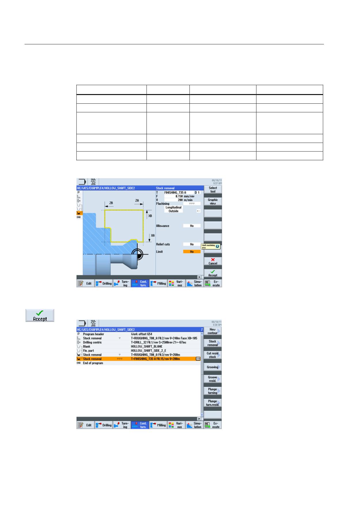
Figure 9-54 Finishing the contour
"Apply" the set values. After acceptance, your work step program looks like this:
Figure 9-55 Process plan following stock removal of the contour
Turning made easy with ShopTurn
184
Training Documents, 09/2011, 6FC5095-0AB80-1BP1
Example 4: Hollow shaft
9.3 Creating the second workpiece side
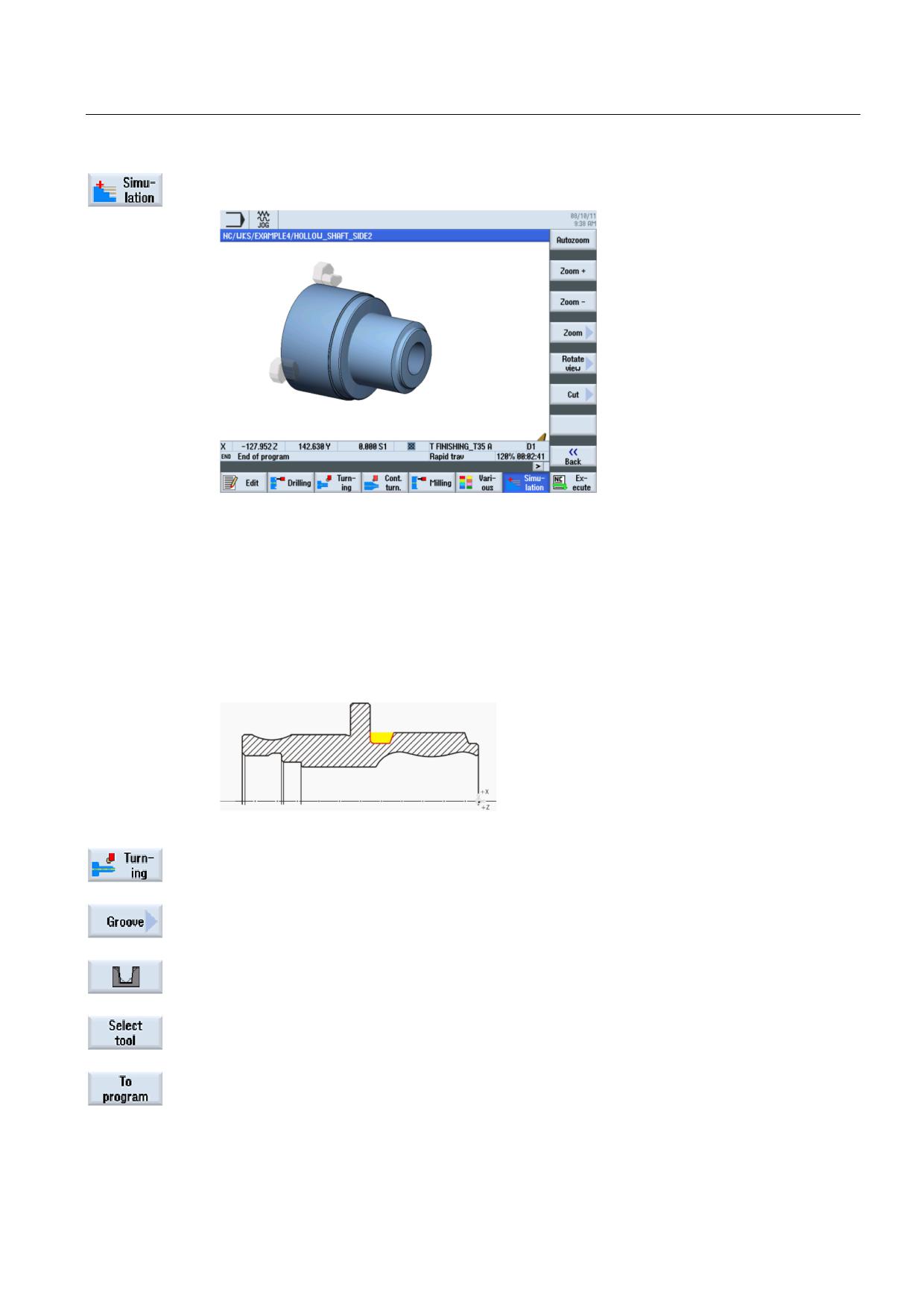
Start the simulation.
Figure 9-56 Simulation - 3D view
9.3.5
Creating an asymmetrical groove
Operating sequences
Proceed as follows to create an asymmetrical groove.
Select the Turning softkey.
Select the Groove softkey.
Select the Groove 2 softkey.
Open the tool list and select the PLUNGE_CUTTER_3 A tool.
Accept the tool into your program.
Turning made easy with ShopTurn
Training Documents, 09/2011, 6FC5095-0AB80-1BP1
185
Example 4: Hollow shaft
9.3 Creating the second workpiece side
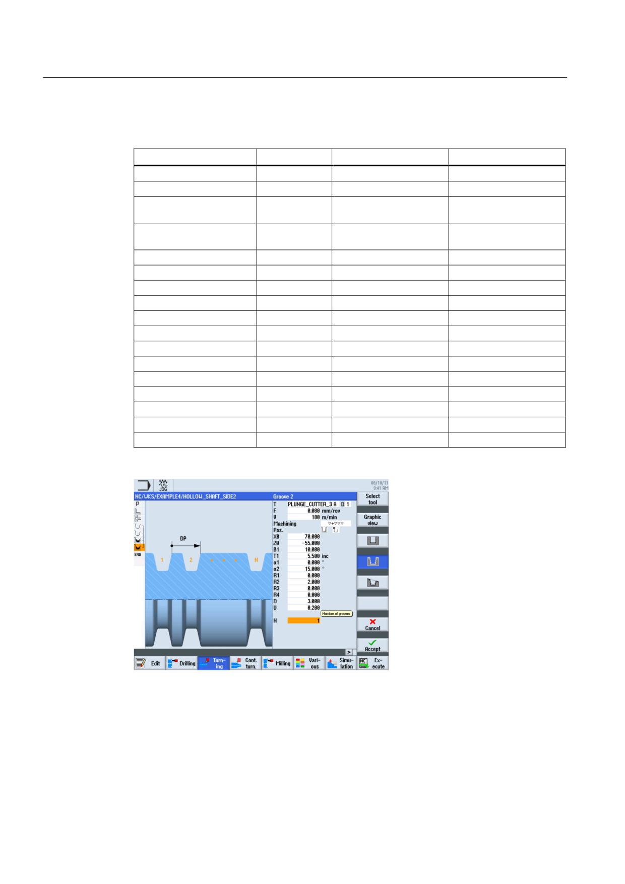
Enter the following values for the groove in the interactive screenform:
Field
Value
Selection via toggle key
Notes
F
0.08
V
180 m/min
X
Machining
Roughing +
X
finishing
Position
see illustration
X
below
X0
70
Z0
-55
B1
10
X (field)
T1
5.5 inc
X
α1
0
α1
15
R1
0
X (field)
R2
2
X (field)
R3
0
X (field)
R4
0
X (field)
D
3
U
0.2
X (field)
N
1
Figure 9-57 Specifying a groove
Turning made easy with ShopTurn
186
Training Documents, 09/2011, 6FC5095-0AB80-1BP1
Example 4: Hollow shaft
9.3 Creating the second workpiece side
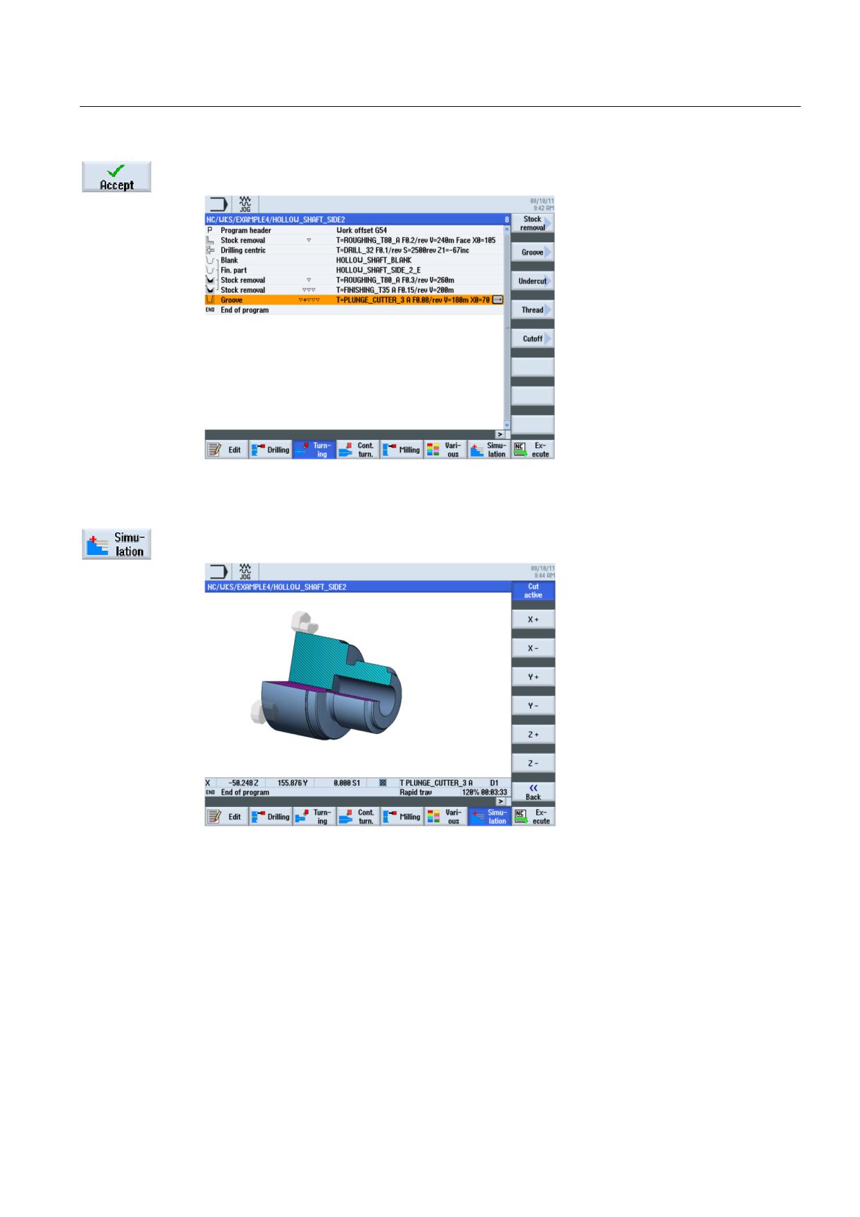
Accept the entered values. After acceptance, the list of work steps looks like this:
Figure 9-58 Process plan following groove
Start the simulation.
Figure 9-59 Simulation - 3D view (cut active)
Turning made easy with ShopTurn
Training Documents, 09/2011, 6FC5095-0AB80-1BP1
187
Example 4: Hollow shaft
9.3 Creating the second workpiece side
9.3.6
Machined part contour of the second side, internal
Operating sequences
Proceed as follows to enter the machined part contour:
Select the Contour turning softkey.
Select the New contour softkey. Enter the name 'HOLLOW_SHAFT_SIDE2_I' for the
contour.
"Apply" your input.
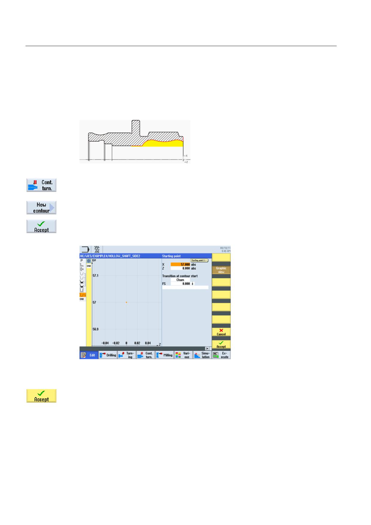
Set the starting point to X57/Z0.
Figure 9-60 Specifying the contour starting point
"Apply" your input.
Turning made easy with ShopTurn
188
Training Documents, 09/2011, 6FC5095-0AB80-1BP1
Example 4: Hollow shaft
9.3 Creating the second workpiece side
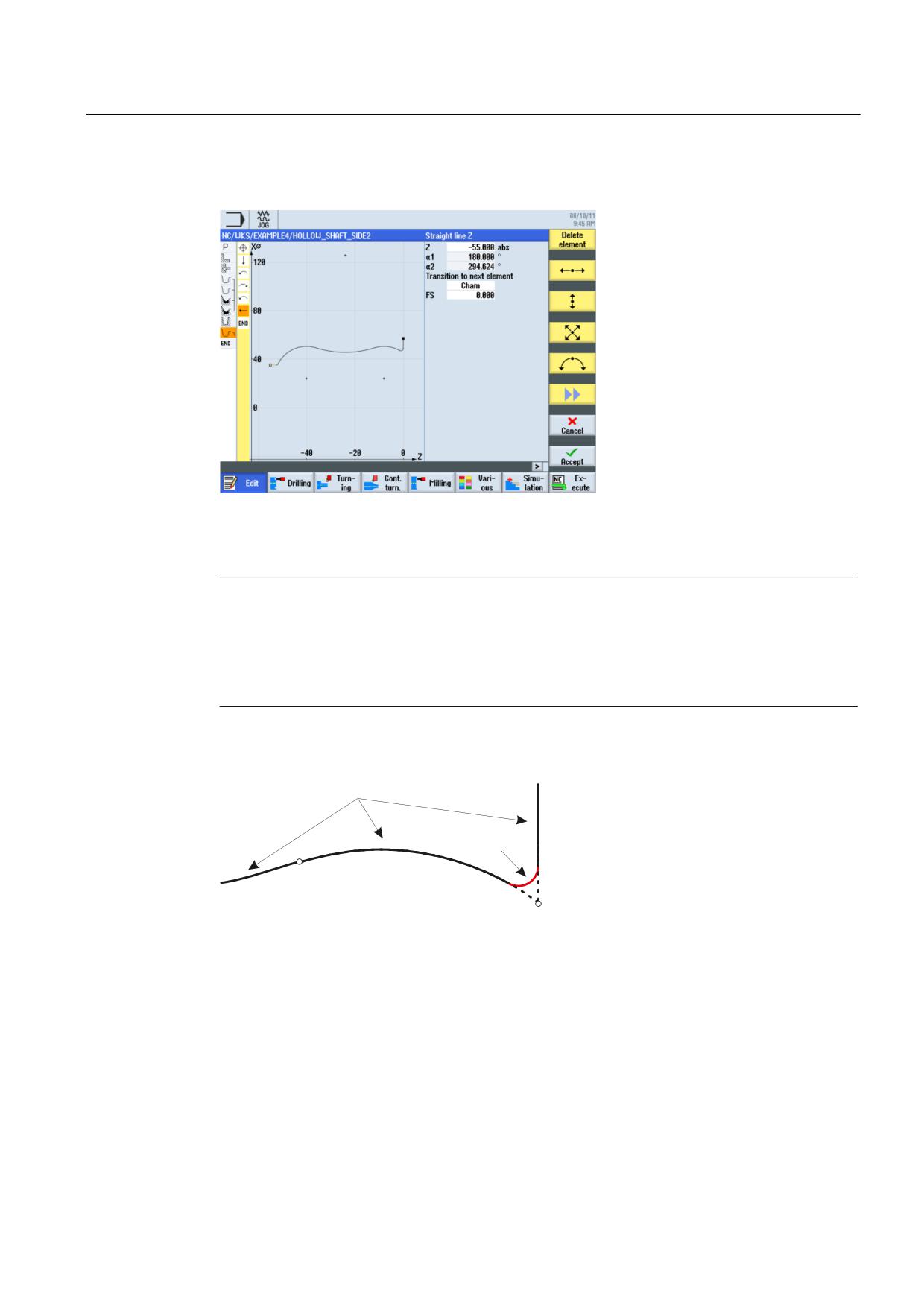
Create the contour without help (see illustration below).
Figure 9-61 Machined part contour of the second side, internal
Note
When creating the contour, ensure that the arc elements merge tangentially.
Tangential merging applies only to main elements, i.e. the rounding is attached to the main
element.
(See illustration below)
0DLQ HOHPHQWV
5RXQGLQJ
WDQJHQWLDO
QRQ WDQJHQWLDO
Turning made easy with ShopTurn
Training Documents, 09/2011, 6FC5095-0AB80-1BP1
189
Example 4: Hollow shaft
9.3 Creating the second workpiece side
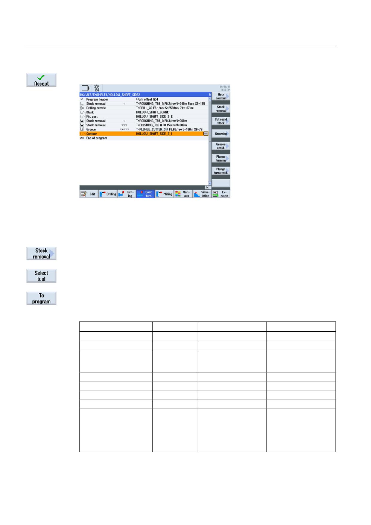
Accept the contour. After accepting the contour, your work step program looks like this.
Figure 9-62 Process plan following input of the contour
Stock removal, residual stock removal and finishing
In the following work step you will perform contour stock removal.
Select the Stock removal softkey.
Open the tool list and select the ROUGHING_T80 I tool.
Accept the tool into your program.
Enter the following values for roughing in the interactive screenform:
Field
Value
Selection via toggle key
Notes
F
0.25
V
280 m/min
X
Machining
longitudinal
X
You must switch the
internal
X
machining to Inside.
roughing
X
D
2.0
UX
0.2
UZ
0.2
DI
0.0
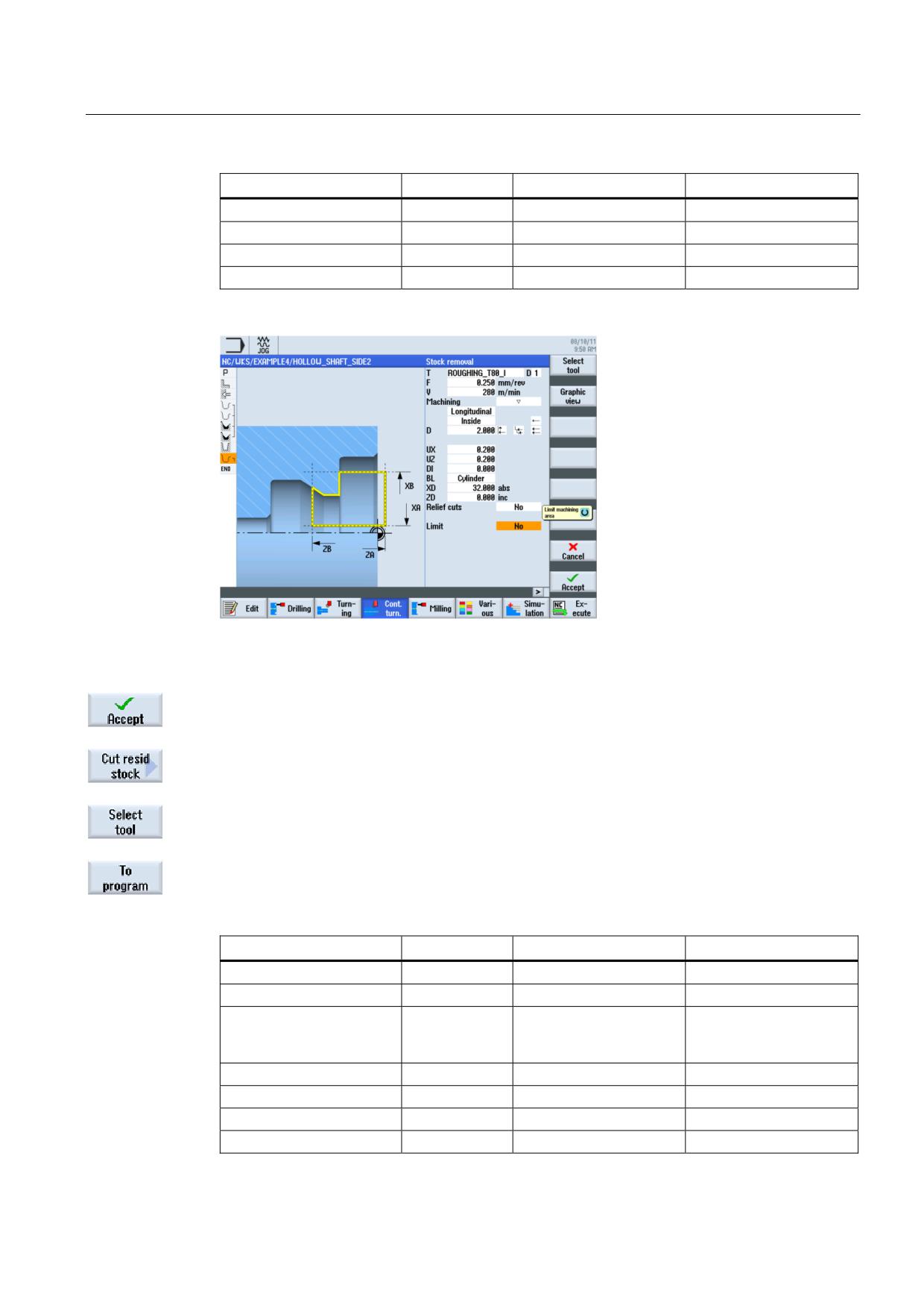
BL
Cylinder
X
Since drilling has already
taken place, you do not
need to take a blank
contour into consideration
for internal machining.
Switch to Cylinder.
Turning made easy with ShopTurn
190
Training Documents, 09/2011, 6FC5095-0AB80-1BP1
Example 4: Hollow shaft
9.3 Creating the second workpiece side
Field
Value
Selection via toggle key
Notes
XD
32 abs
X
ZD
0 abs
X
Relief cuts
No
X
Set machining area limits
No
X
Figure 9-63 Roughing the contour
"Apply" the set values.
Select the Residual stock removal softkey.
Open the tool list and select the FINISHING_T35 I tool.
Accept the tool into your program.
Enter the following values for finishing in the interactive screenform:
Field
Value
Selection via toggle key
Notes
F
0.2
V
240 m/min
X
Machining
longitudinal
X
internal
X
finishing
X
Allowance
No
X
Relief cuts
Yes
X
FR
0.2
Set machining area limits
No
X
Turning made easy with ShopTurn
Training Documents, 09/2011, 6FC5095-0AB80-1BP1
191
Example 4: Hollow shaft
9.3 Creating the second workpiece side
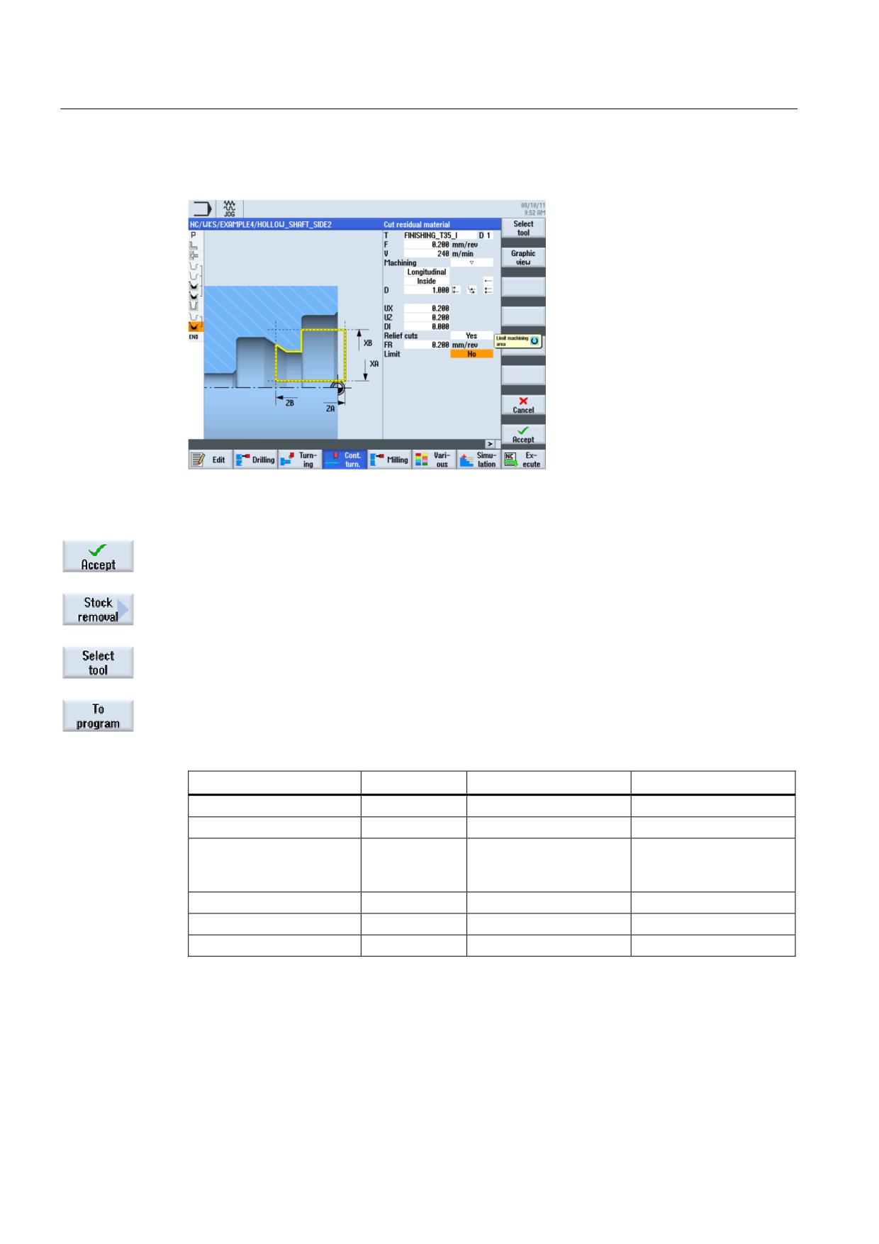
Figure 9-64 Contour residual stock removal
"Apply" the set values.
Select the Stock removal softkey.
Open the tool list and select the FINISHING_T35 I tool.
Accept the tool into your program.
Enter the following values for finishing in the interactive screenform:
Field
Value
Selection via toggle key
Notes
F
0.12
V
280 m/min
X
Machining
longitudinal
X
internal
X
finishing
X
Allowance
No
X
Relief cuts
Yes
X
Set machining area limits
No
X
Turning made easy with ShopTurn
192
Training Documents, 09/2011, 6FC5095-0AB80-1BP1
Example 4: Hollow shaft
9.3 Creating the second workpiece side
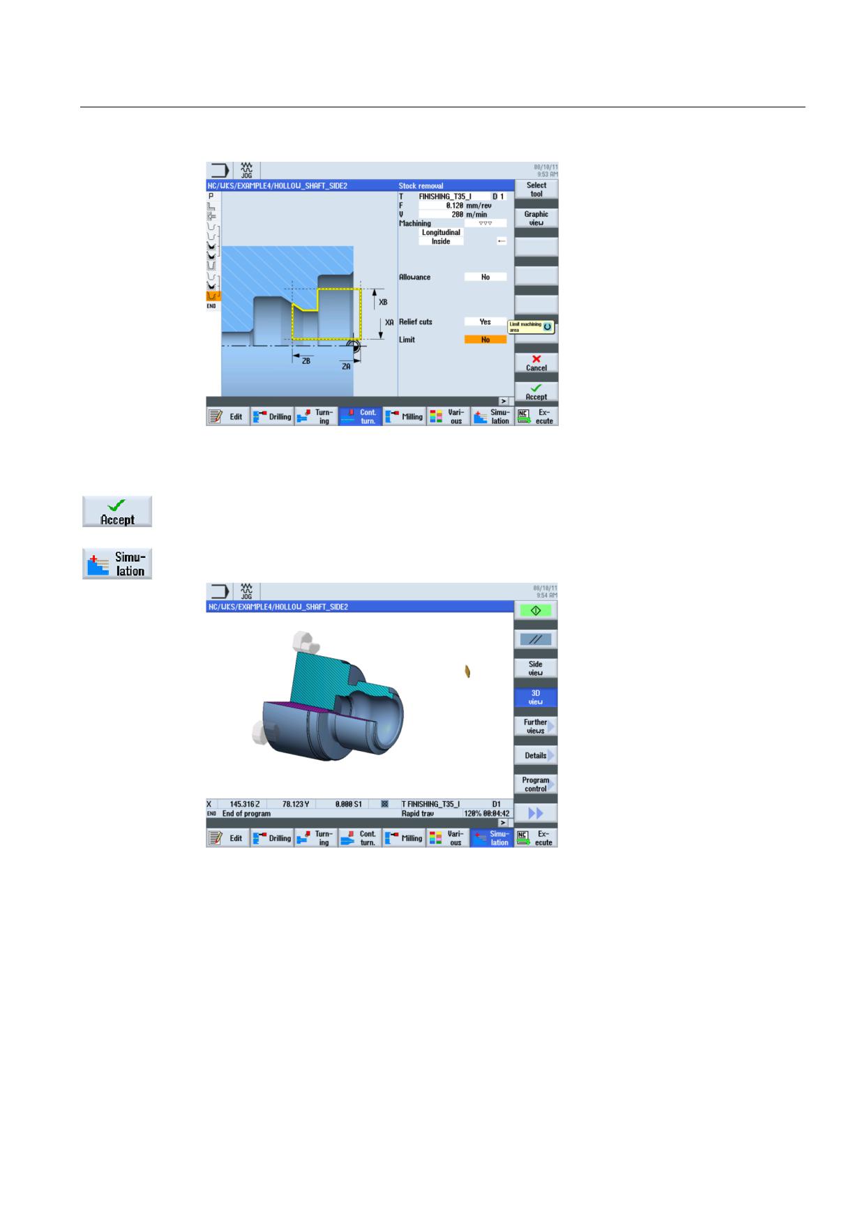
Figure 9-65 Finishing the contour
"Apply" the set values.
Start the simulation to perform checks.
Figure 9-66 Simulation - 3D view (cut active)
Turning made easy with ShopTurn
Training Documents, 09/2011, 6FC5095-0AB80-1BP1
193
Example 5: Plunge-turning
10
10.1
Overview
Learning objectives
In this section you will learn how to use the plunge-turning functions.
Task
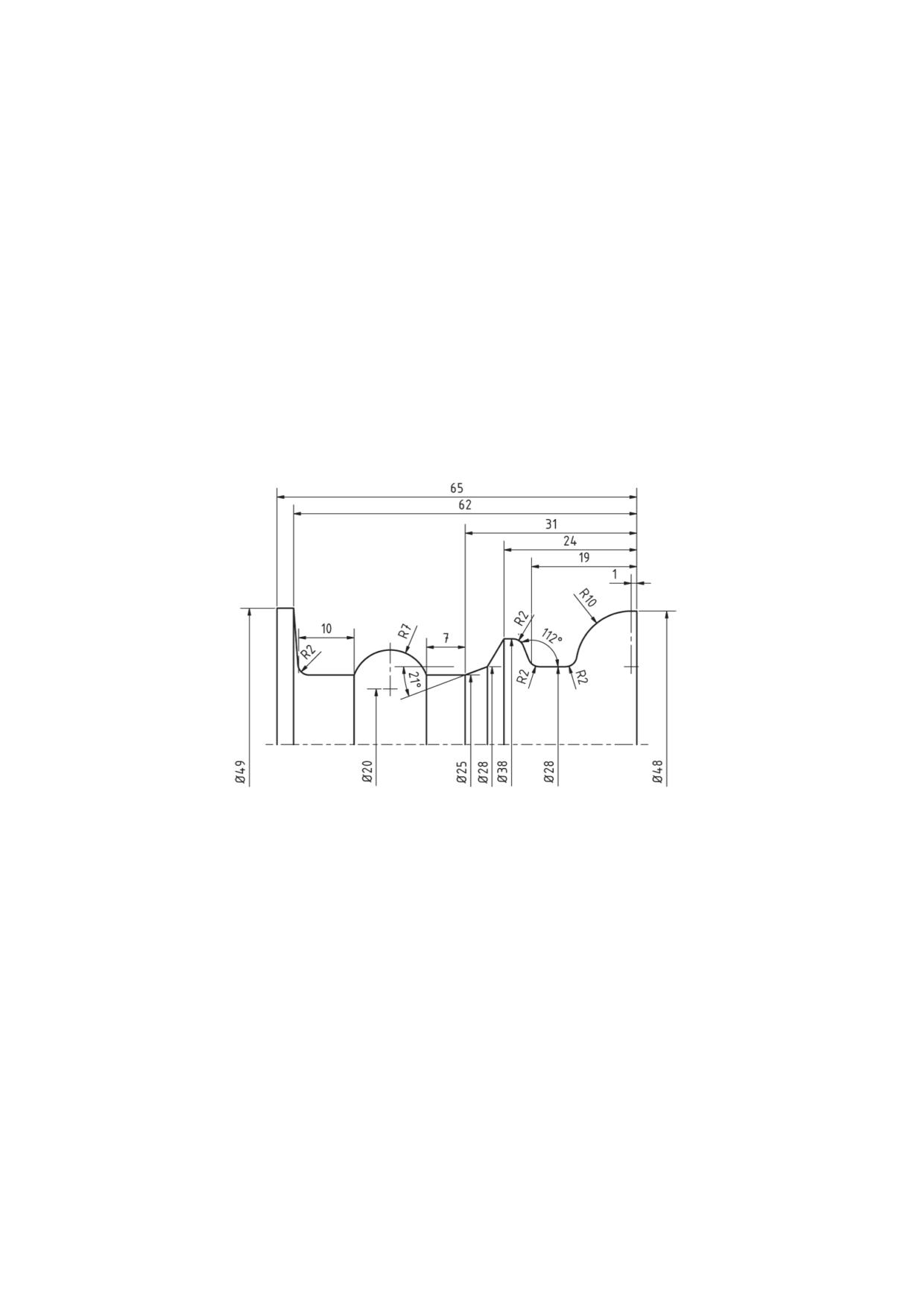
Figure 10-1 Workshop drawing - Example 5:
Turning made easy with ShopTurn
Training Documents, 09/2011, 6FC5095-0AB80-1BP1
195
Example 5: Plunge-turning
10.2 Plunge-turning
Preparation
Perform the following steps without help:
1. Create a new workpiece with the name 'EXAMPLE5'.
2. Create a new step sequence program with the name 'PLUNGE_TURNING'.
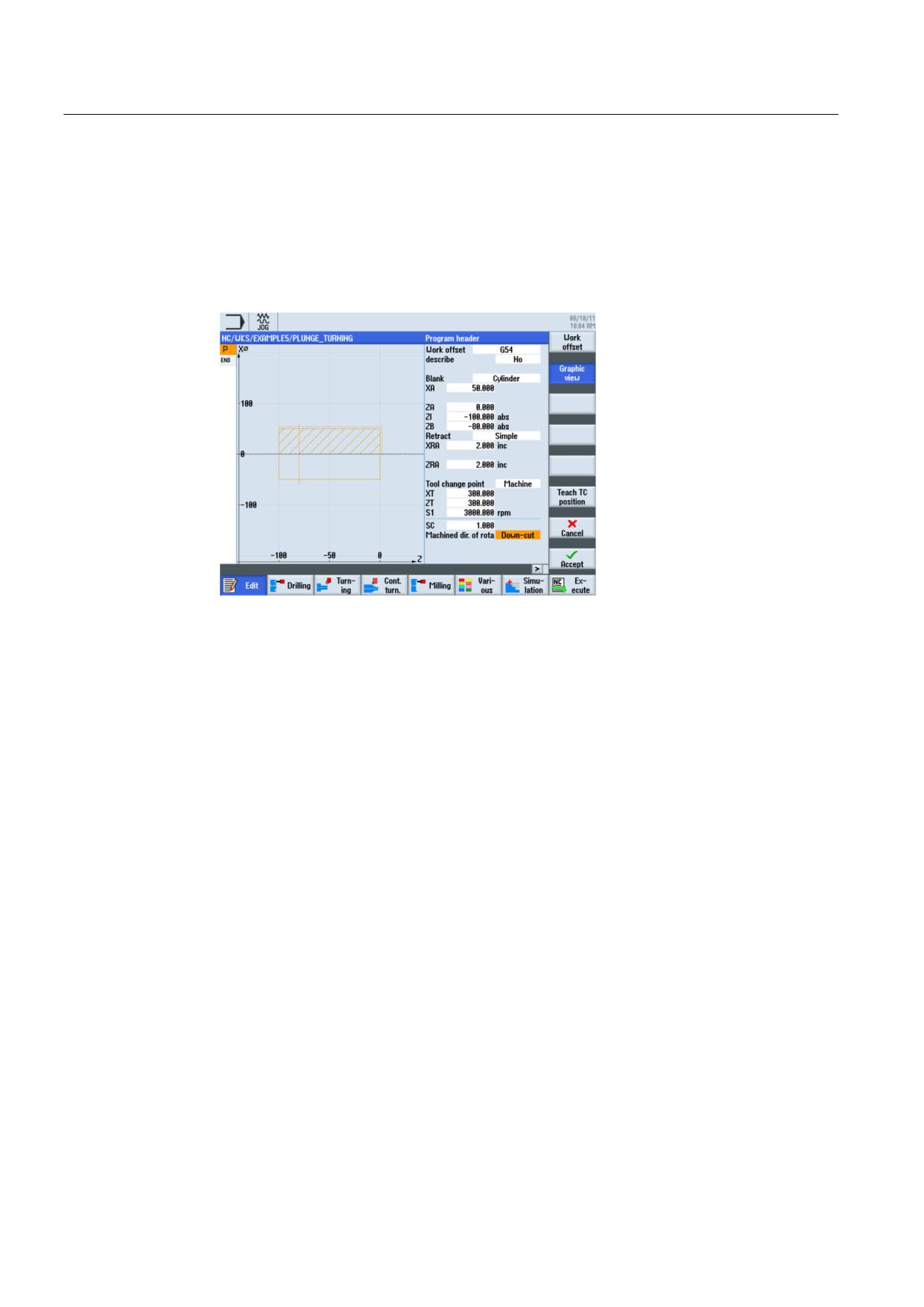
3. Fill in the program header (see illustration below).
Figure 10-2 Creating a program header
10.2
Plunge-turning
The achievable level of productivity during turning is limited, among other things, by the
possible number of tools in the revolver and the frequent tool changes required for effective
turning machining. With standard turning tools alone, not all possible contours can be
produced, and residual material machining, therefore, is often performed by means of
plunge-cutting. For the complete machining of a contour, therefore, it is always necessary to
change between standard turning tools and plunge-cutting tools.
The aim of the plunge-turning cycle is to reduce the number of tool changes and to avoid
empty cuts, such as those that occur during the backward movement of the turning tool, for
example.
As a general rule, hardly any empty cuts exist during the plunge-turning cycle, as stock
removal is performed during both forward and backward movement. This must be taken into
account during program creation. ShopTurn offers optimum support for this. As you already
know, you only need to describe the contour of the turning part and during the stock removal
cycle you can select whether you wish to perform stock removal using a conventional
procedure or by means of plunge-cutting or plunge-turning. ShopTurn automatically
calculates the cuts and traversing movements of the tool based on the cycle. This means
that empty cuts are eliminated to a great extent.
During the simulation, you can clearly analyze the calculated traversing movements of the
tool. Even a combination of conventional turning machining and plunge-turning is possible,
i.e. a standard tool is used for roughing, while plunge-turning is used for machining residual
material, meaning that the contour can be thoroughly machined without the risk of damage.
Turning made easy with ShopTurn
196
Training Documents, 09/2011, 6FC5095-0AB80-1BP1
Example 5: Plunge-turning
10.3 Creating the contour
10.3
Creating the contour
Operating sequences
Create the contour without help.
Select the Contour turning softkey.
Select the New contour softkey. Enter the name 'CONTOUR_E' for the contour.
Confirm your input.
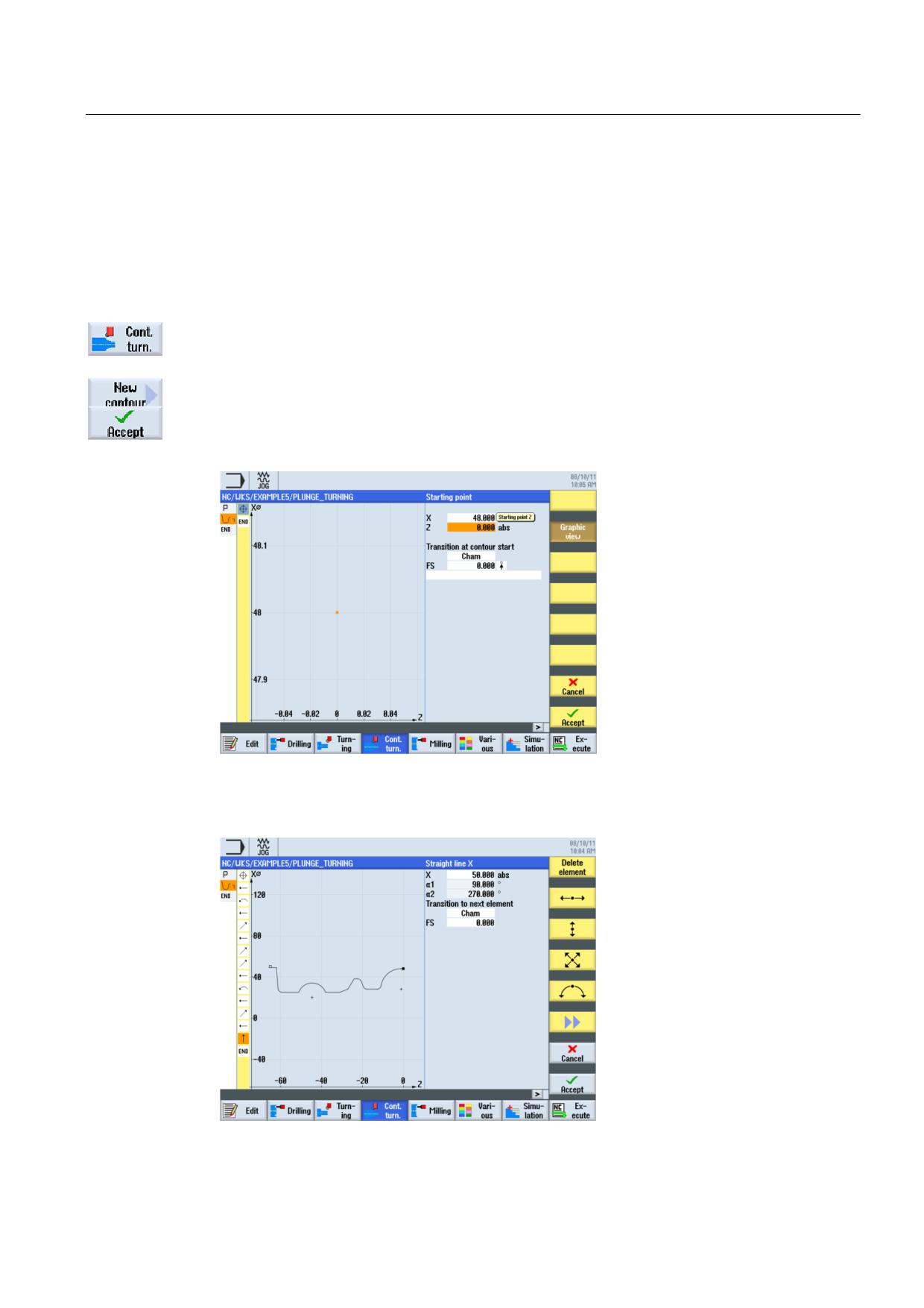
Set the starting point to X48/Z0.
Figure 10-3 Specifying the contour starting point
Create a contour (see illustration below).
Figure 10-4 Contour in the contour calculator
Turning made easy with ShopTurn
Training Documents, 09/2011, 6FC5095-0AB80-1BP1
197
Example 5: Plunge-turning
10.4 Stock removal with the plunge-turning cycle
10.4
Stock removal with the plunge-turning cycle
Operating sequences
In the following work step you will perform contour stock removal.
To this end, proceed as follows:
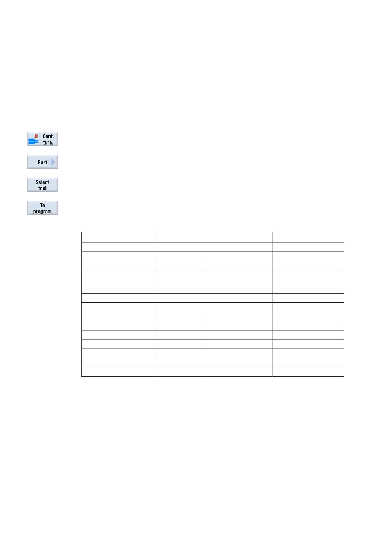
Select the Contour turning softkey.
Select the Plunge-turning softkey.
Open the tool list and select the PLUNGE_CUTTER_3 A tool.
Accept the tool into your program.
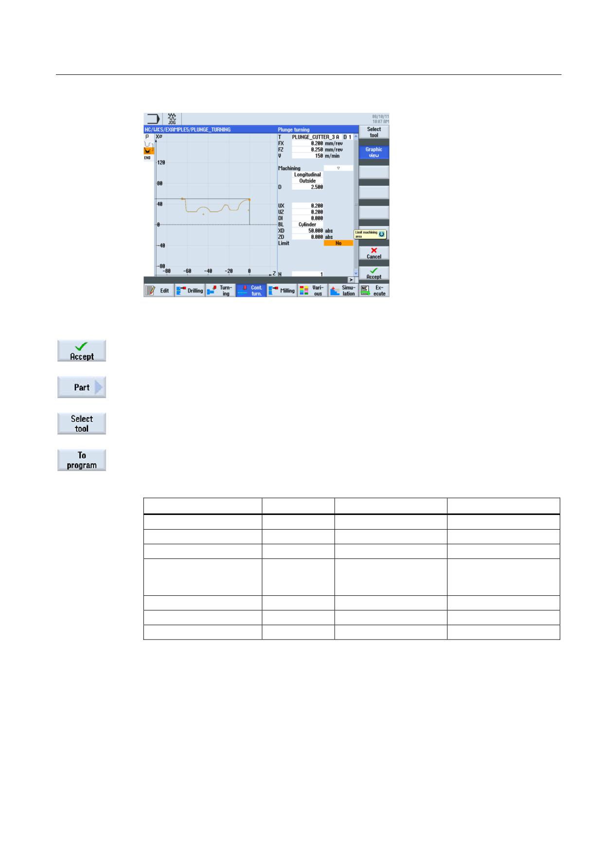
Enter the following values for roughing in the interactive screenform:
Field
Value
Selection via toggle key
Notes
FX
0.2
FZ
0.25
V
150 m/min
X
Machining
longitudinal
X
external
X
roughing
X
D
2.5
UX
0.2
UZ
0.2
DI
0.0
BL
Cylinder
X
XD
50 abs
X
ZD
0 abs
X
Set machining area limits
No
X
N
1
Turning made easy with ShopTurn
198
Training Documents, 09/2011, 6FC5095-0AB80-1BP1
Example 5: Plunge-turning
10.4 Stock removal with the plunge-turning cycle
Roughing the contour
Accept the entered values.
Select the Plunge-turning softkey.
Open the tool list and select the PLUNGE_CUTTER_3 A tool.
Accept the tool into your program.
Enter the following values for finishing in the interactive screenform:
Field
Value
Selection via toggle key
Notes
FX
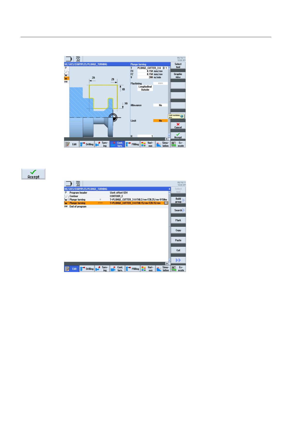
0.15
FZ
0.15
V
200 m/min
X
Machining
longitudinal
X
external
X
finishing
X
Allowance
No
X
Set machining area limits
No
X
N
1
Turning made easy with ShopTurn
Training Documents, 09/2011, 6FC5095-0AB80-1BP1
199
Example 5: Plunge-turning
10.4 Stock removal with the plunge-turning cycle
Finishing the contour
Accept the entered values. After acceptance, your work step program looks like this:
Figure 10-5 Work step program
Turning made easy with ShopTurn
200
Training Documents, 09/2011, 6FC5095-0AB80-1BP1
Example 5: Plunge-turning
10.4 Stock removal with the plunge-turning cycle
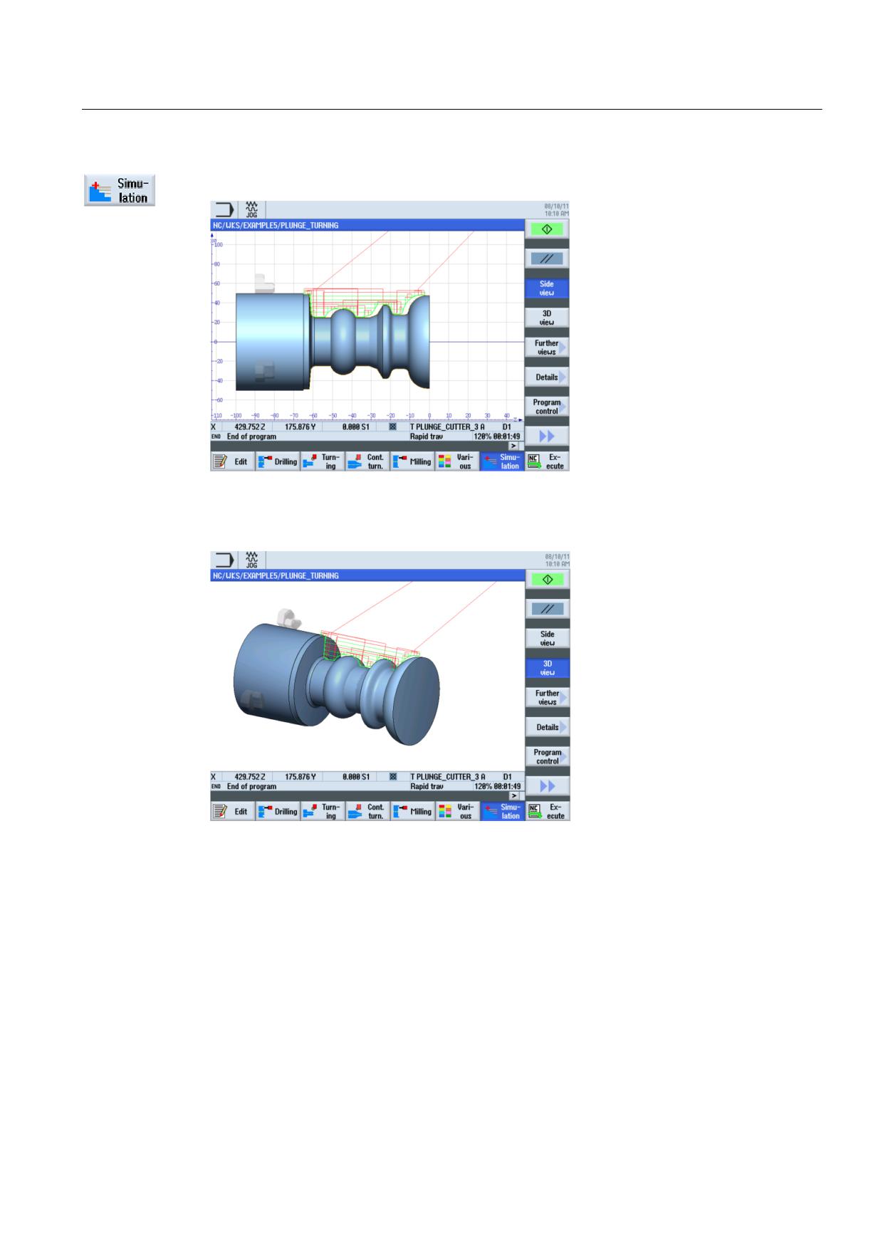
Select the Simulation softkey.
Figure 10-6 Simulation - Side view (with display of the traversing paths)
Figure 10-7 Simulation - 3D view (with display of the traversing paths)
Turning made easy with ShopTurn
Training Documents, 09/2011, 6FC5095-0AB80-1BP1
201
And now you can start manufacturing!
11
After you have acquired a well-founded knowledge of the creation of process plans in
ShopTurn by working with the examples, we will now machine workpieces.
To machine a workpiece, proceed as follows:
Approaching reference point
After turning on the control system and before traversing the axes according to the process
plans or traversing manually, you will have to approach the reference point of the machine.
In this way, ShopTurn will find the start of counting in the position measuring system of the
machine.
Since approaching of the reference point is different depending on machine type and
manufacturer, only a few hints can be given here for orientation:
1. If necessary traverse the tool to a free point in the work space from which traversing is
possible in all directions without collision. Make sure that the tool is then not beyond the
reference point of the corresponding axis (since reference point approach is only
performed in one direction for each axis; otherwise, this point cannot be reached).
2. Perform the reference point approach exactly according to the specifications of the
machine manufacturer.
Clamping the workpiece
To guarantee machining in accordance with the specified dimensions and, naturally, also for
your own safety, it is imperative to clamp the workpiece tightly. A three-block chuck is usually
used for this.
Setting the workpiece zero
Since ShopTurn cannot guess where in the work space the workpiece is located, you must
determine the workpiece zero in Z.
The workpiece zero is usually determined through sampling with a calculated tool in the Z
axis.
Executing the process plan
Now the machine is prepared, the workpiece is set up, and the tools are gauged. At last we
can start!
Turning made easy with ShopTurn
Training Documents, 09/2011, 6FC5095-0AB80-1BP1
203
And now you can start manufacturing!
11.1 And now you can start manufacturing!
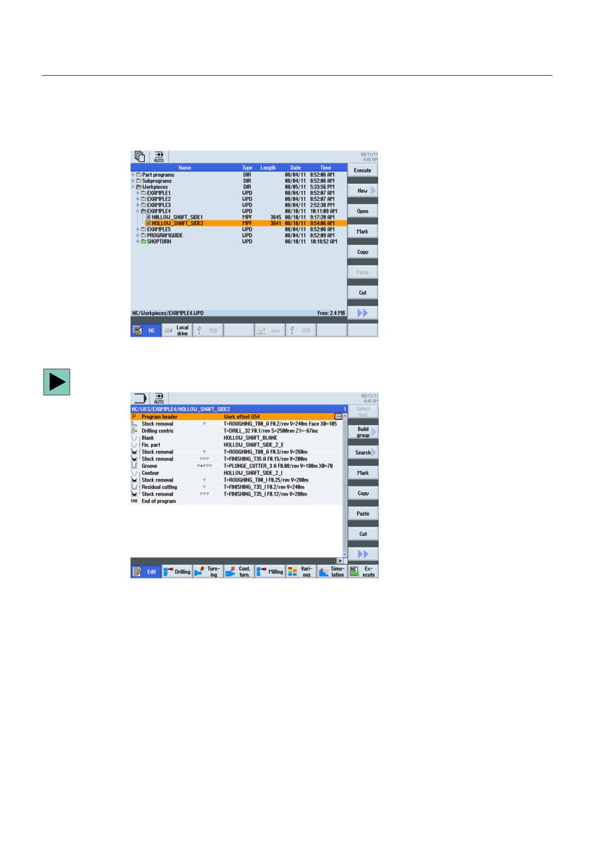
First select the program you want to execute in the Program Manager, e.g.
HOLLOW_SHAFT_SIDE2.
Figure 11-1 Selecting the program
Open the program.
Figure 11-2 Opening the process plan
Turning made easy with ShopTurn
204
Training Documents, 09/2011, 6FC5095-0AB80-1BP1
And now you can start manufacturing!
11.1 And now you can start manufacturing!
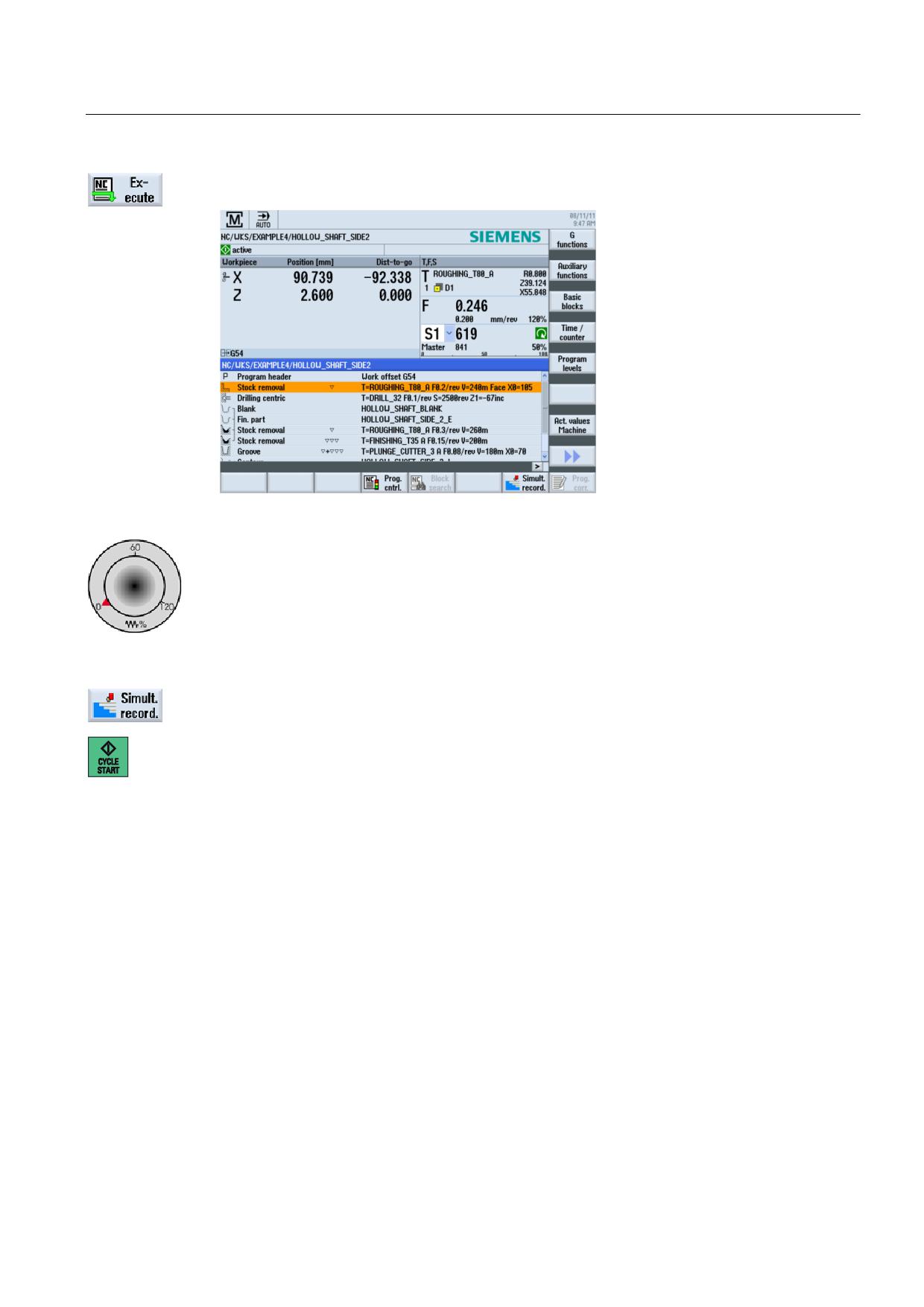
Select the NC selection softkey.
Figure 11-3 Executing
Due to the fact that the process plan has not yet been executed with control, turn the
feedrate potentiometer to zero position to ensure that you keep everything under control
from the beginning.
If you also want to see a simulation during machining, select the Drawing softkey before
starting. Only then are all traversing paths and their effects are displayed.
Start machining and check the speed of the tool motions using the feedrate potentiometer.
Turning made easy with ShopTurn
Training Documents, 09/2011, 6FC5095-0AB80-1BP1
205
How accomplished are you in the use of ShopTurn?
12
12.1
Exercise 1
Will you manage this task using ShopTurn within 10 minutes?
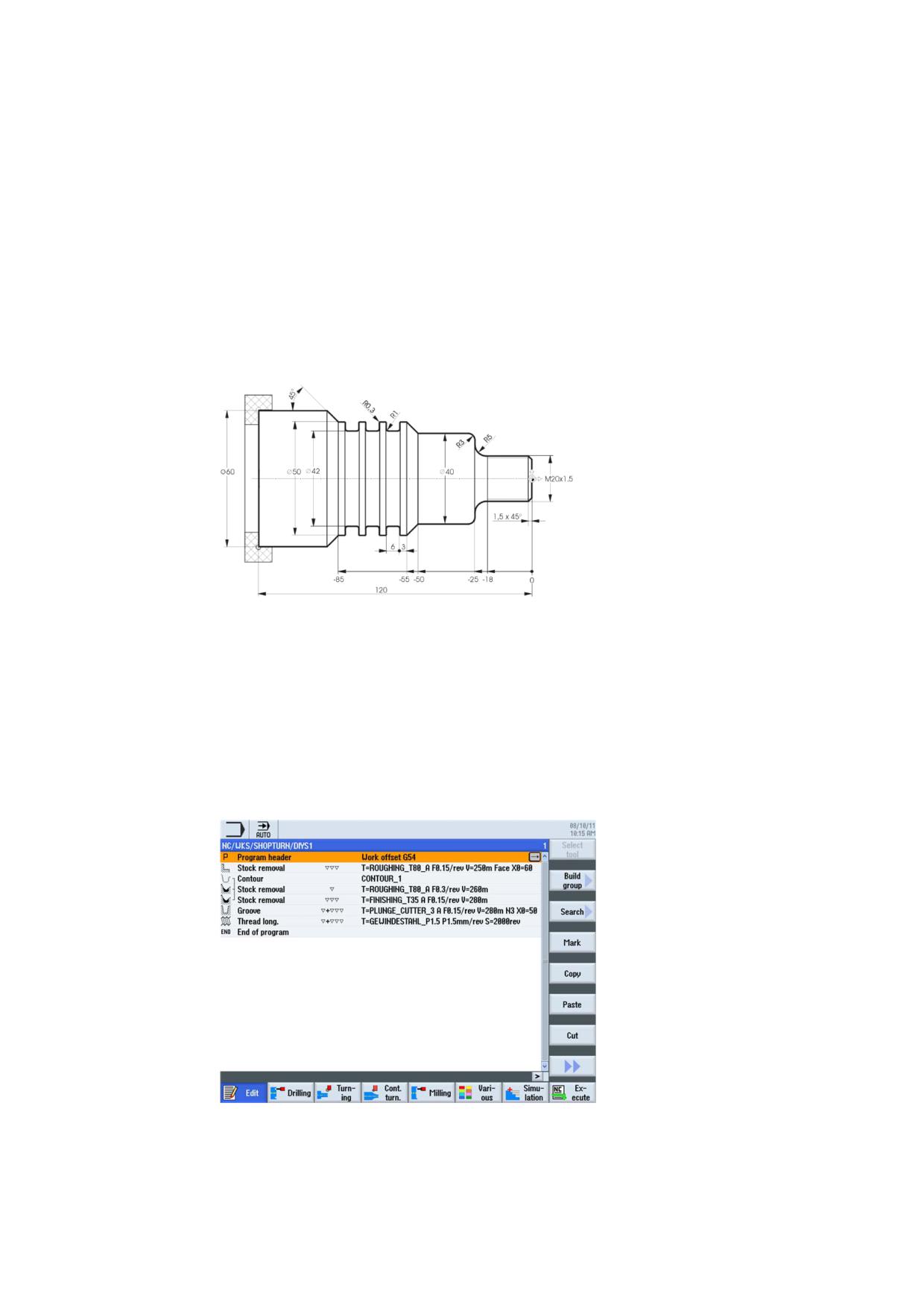
Figure 12-1 Workshop drawing DIYS1
Notes
In the process plan, the workpiece is milled to size in two work steps (see model below). For
this reason, you can assign the the starting point of the CONTOUR_1 contour to the start of
the first chamfer.
Model
Figure 12-2 Process plan
Turning made easy with ShopTurn
Training Documents, 09/2011, 6FC5095-0AB80-1BP1
207
How accomplished are you in the use of ShopTurn?
12.1 Exercise 1
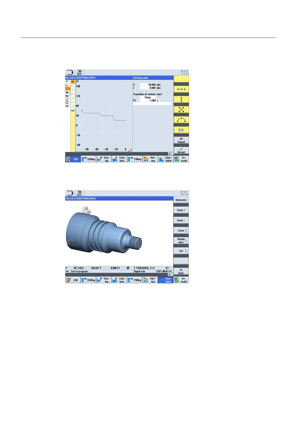
Figure 12-3 Contour in the contour calculator
Figure 12-4 Workpiece simulation
Turning made easy with ShopTurn
208
Training Documents, 09/2011, 6FC5095-0AB80-1BP1
How accomplished are you in the use of ShopTurn?
12.2 Exercise 2
12.2
Exercise 2
Will you manage this task using ShopTurn within 10 minutes?
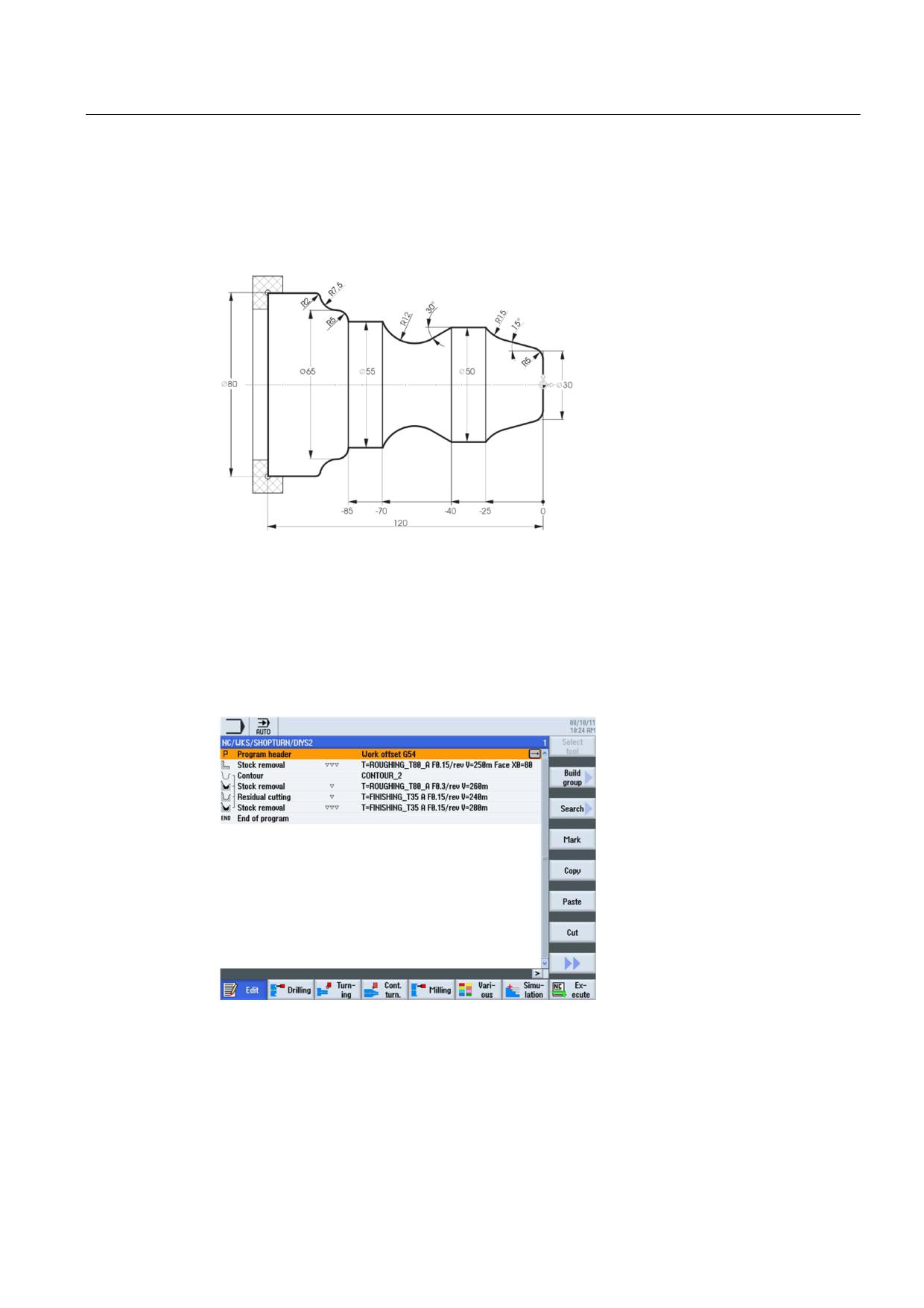
Figure 12-5 Workshop drawing DIYS2
Notes
You can use the automatic cutting of residual material to great effect here.
Model
Figure 12-6 Process plan
Turning made easy with ShopTurn
Training Documents, 09/2011, 6FC5095-0AB80-1BP1
209
How accomplished are you in the use of ShopTurn?
12.2 Exercise 2
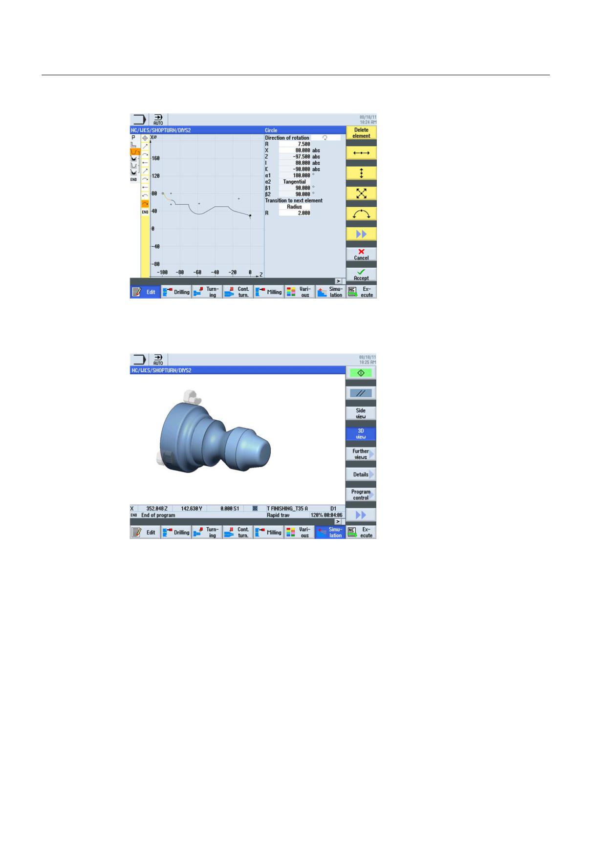
Figure 12-7 Contour in the contour calculator
Figure 12-8 Workpiece simulation
Turning made easy with ShopTurn
210
Training Documents, 09/2011, 6FC5095-0AB80-1BP1
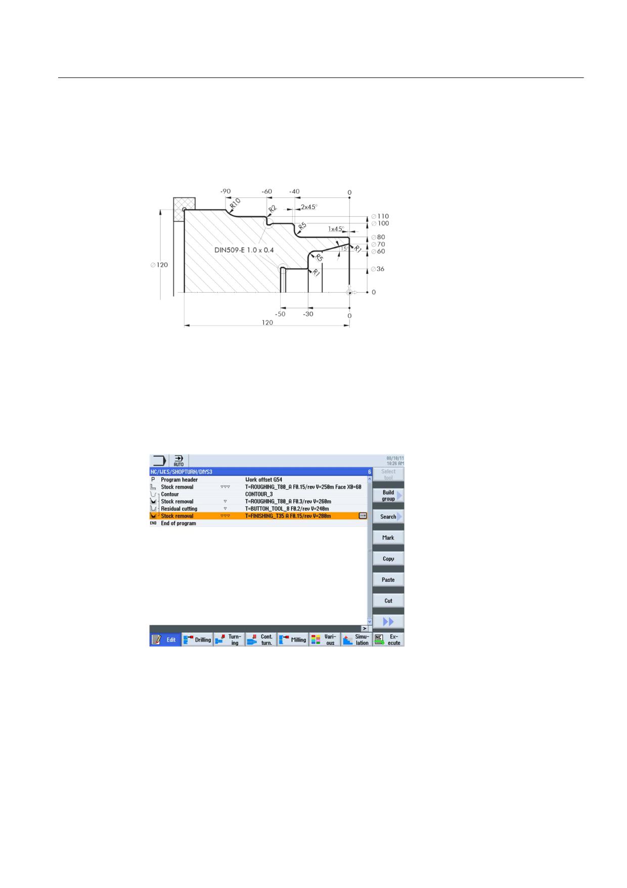
How accomplished are you in the use of ShopTurn?
12.3 Exercise 3
12.3
Exercise 3
Will you manage this task using ShopTurn within 10 minutes?
Figure 12-9 Workshop drawing DIYS3
Notes
Construct radius 5 in two steps.
Model
Figure 12-10 Process plan
Turning made easy with ShopTurn
Training Documents, 09/2011, 6FC5095-0AB80-1BP1
211
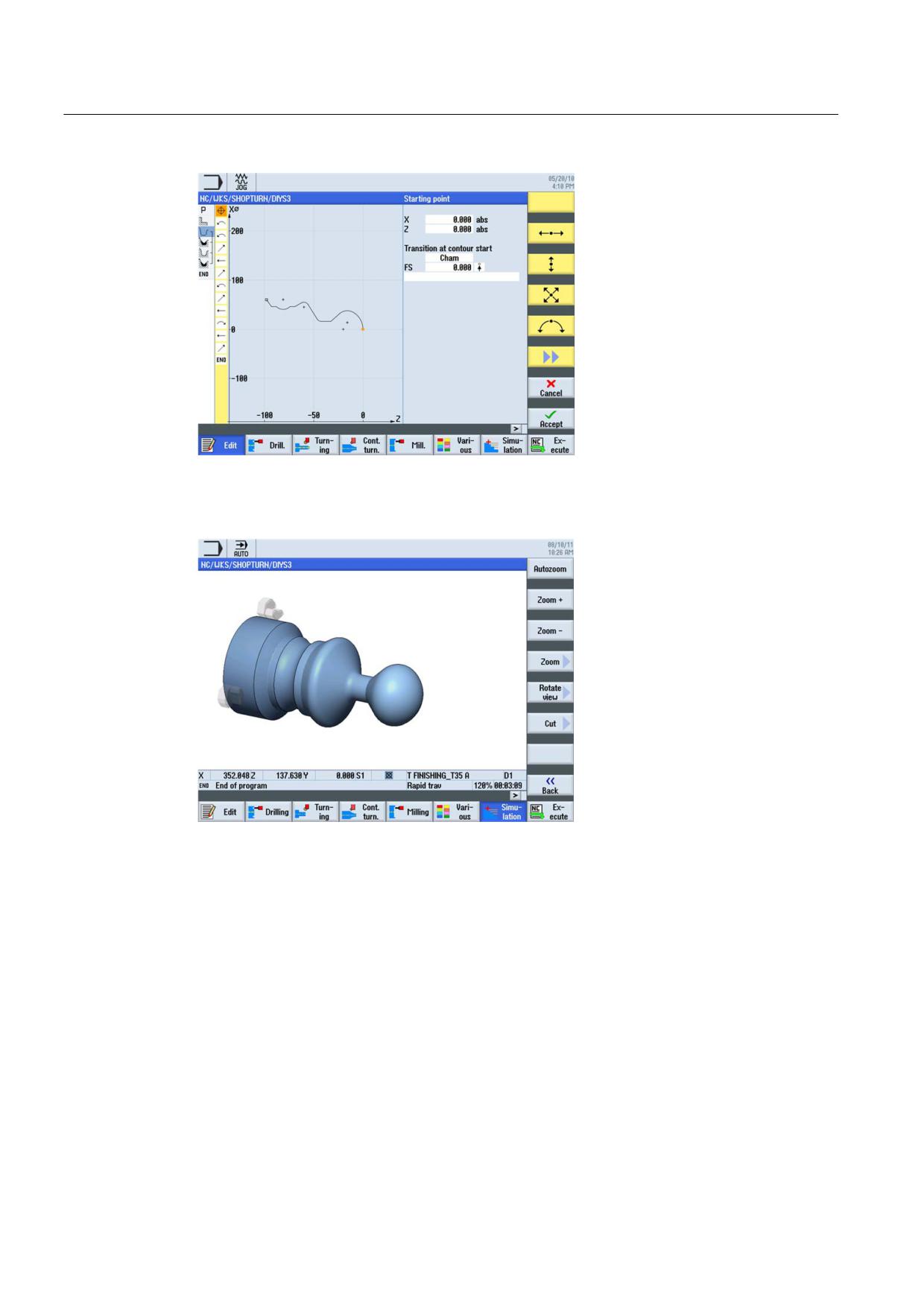
How accomplished are you in the use of ShopTurn?
12.3 Exercise 3
Figure 12-11 Contour in the contour calculator
Figure 12-12 Workpiece simulation
Turning made easy with ShopTurn
212
Training Documents, 09/2011, 6FC5095-0AB80-1BP1
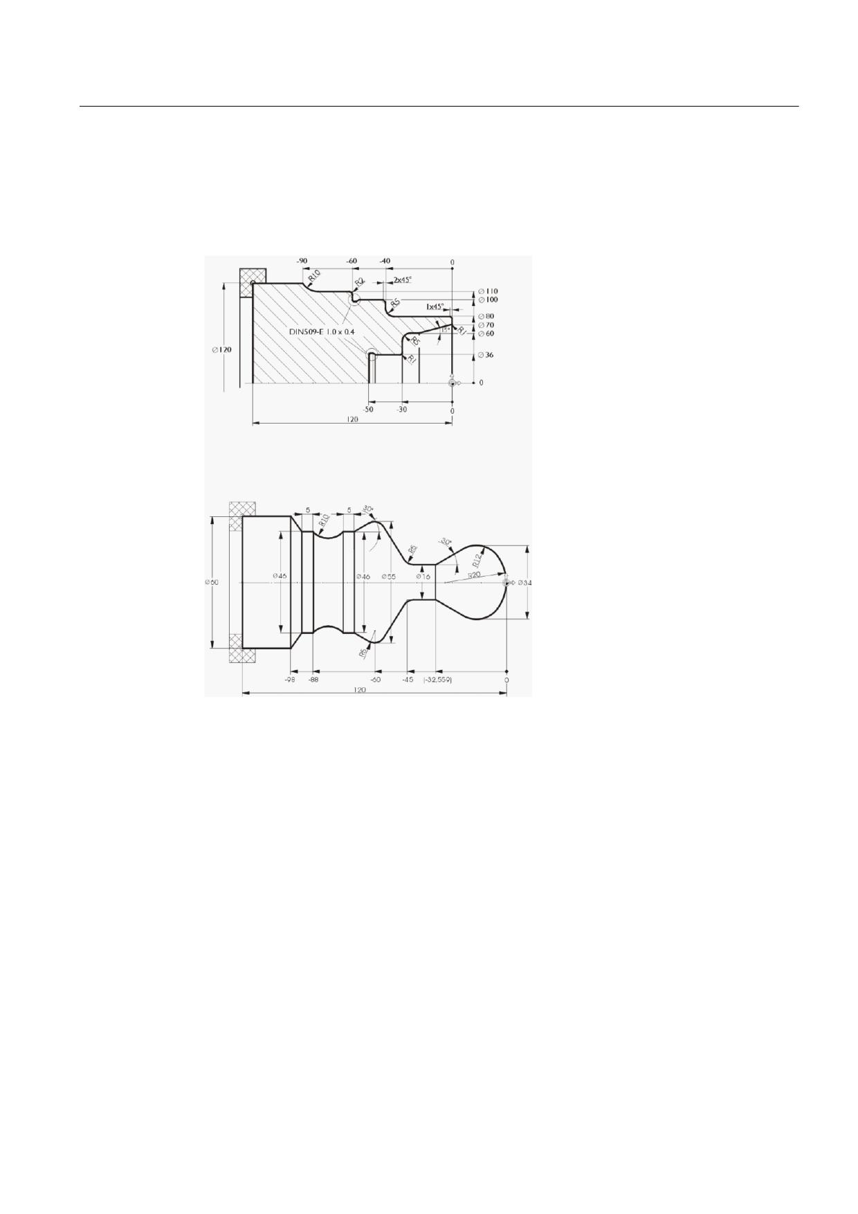
How accomplished are you in the use of ShopTurn?
12.4 Exercise 4
12.4
Exercise 4
Will you manage this task using ShopTurn within 15 minutes?
Figure 12-13 Workshop drawing DIYS4
Notes
In the process plan, the end face is roughed and finished first (see model below). Then the
entire external area, including the undercut, is produced. Following this, the internal part of
the contour is machined. The starting point of the internal contour is set to X70/Z0. You can
copy the external and internal machining sequences using the work step editor by means of
cut and paste.
Turning made easy with ShopTurn
Training Documents, 09/2011, 6FC5095-0AB80-1BP1
213
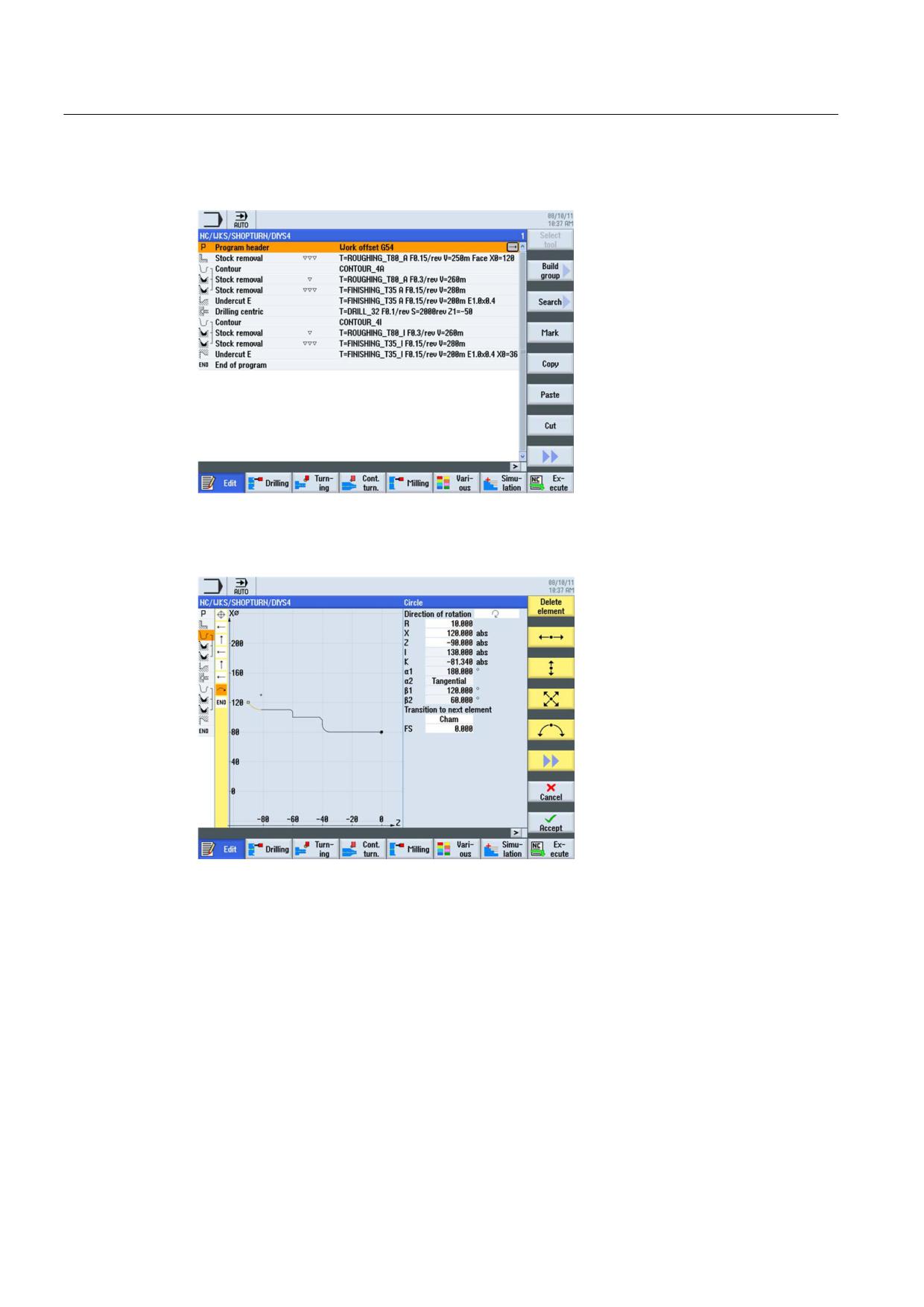
How accomplished are you in the use of ShopTurn?
12.4 Exercise 4
Model
Figure 12-14 Process plan
Figure 12-15 External contour in the contour calculator
Turning made easy with ShopTurn
214
Training Documents, 09/2011, 6FC5095-0AB80-1BP1
How accomplished are you in the use of ShopTurn?
12.4 Exercise 4
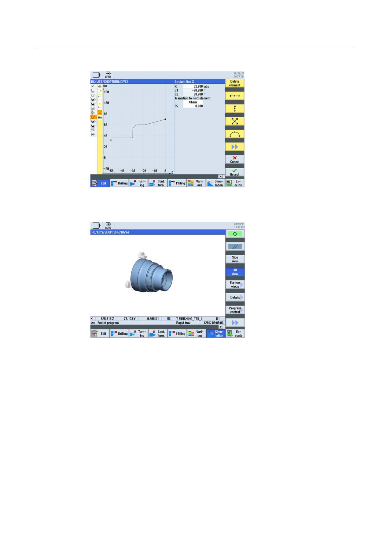
Figure 12-16 Internal contour in the contour calculator
Figure 12-17 Workpiece simulation
Turning made easy with ShopTurn
Training Documents, 09/2011, 6FC5095-0AB80-1BP1
215
How accomplished are you in the use of ShopTurn?
12.4 Exercise 4
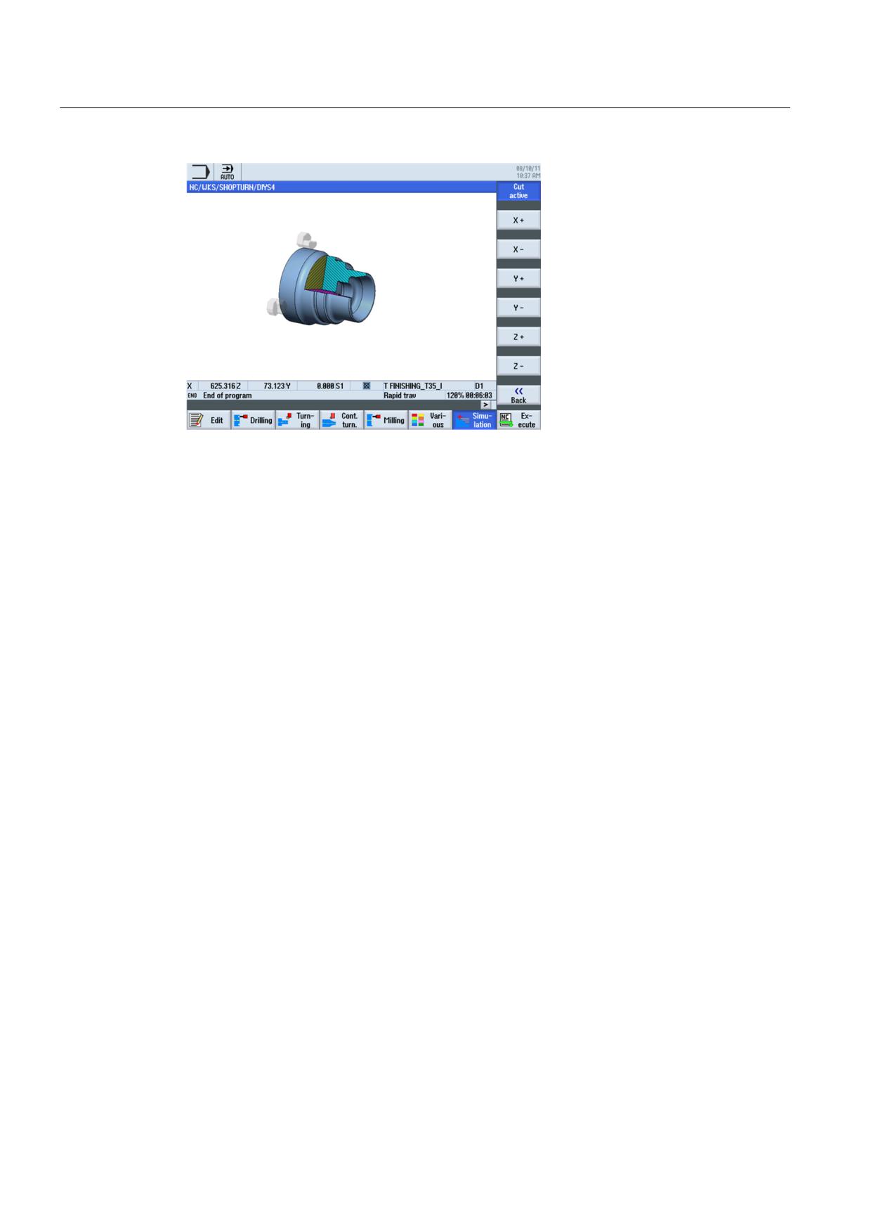
Figure 12-18 Workpiece simulation - Cut active
Turning made easy with ShopTurn
216
Training Documents, 09/2011, 6FC5095-0AB80-1BP1