SINUMERIK 840D sl. Training. Operate - Turning (2016-2020) - page 25

Mirror, offset, rotate, scale for turning
M510
Program for the washer 2 with dwell time
N10 G18 G54 G64 LIMS=4000
N20 SCALE X0.737 Z0.737
; Scaling
N30 LBL14:
N40 G00 X300 Z400
N50 T1
; Roughing tool
N60 G96 S160 F0.2 M4 D1
N70 G00 X44 Z0.2 M8
N80 G01 X-1.6
N90 Z3
N100 G00 G42 X14 Z2
N110 G01 Z0
N120 X38 RND=1.5
N130 Z-8
N140 X42
N150 G00 G40 X200 Z300
N160 T10
; Core drill Ø16mm
N170 G97 S2500 F0.15 M4 D1
N180 G00 X0 Z3 M8
N190 G01 Z-7
N200 G00 Z3
N210 G00 X200 Z300
N220 T3
; Parting tool 3mm wide
N230 G96 S140 F0.1 M4 D2
; Right hand cutting edge activated
N240 G00 X40 Z-4
N250 G01 X30
N260 G04 F0.5
; Dwell time 0,5 sec
N270 G01 X22
N280 G04 S5
; Dwell time 5 revolutions
N250 G01 X14
N260 G00 X40
N270 ATRANS Z-8
; Offset additive
N280 REPEAT LBL14 P2
; Repeat
N290 TRANS
; Cancel all Frames
N300 G00 X200 Z300
N310 M30
M510: END
Notes
828D/840Dsl SINUMERIK Operate
Page 11
M510

M510
Mirror, offset, rotate, scale for turning
Notes
M510
Page 12
828D/840Dsl SINUMERIK Operate
M701
Drawings of programming examples
Sinumerik
Operate
Module Description:
This module contains all the drawings that were used in the individual modules so far and additional
work piece drawings as exercises for the consolidation of the acquired knowledge.
Module Objective:
This module provides the means to carry out further exercises regarding the programming with Shop-
Turn and to consolidate the programming knowledge so far attained.
Content:
Shop drawings
- Bolt_1
- Bolt_2
- Shaft_1
- Spigot_1
- Pin
- Stepped shaft
- Contour spigot
- Joint shaft
- Bowling pin
- Core
- Kidney
- Fitting shaft
- Example counter spindle
- Hub
This document was produced for training purposes.
828D/840Dsl SINUMERIK Operate
Page 1
M701
Siemens assumes no responsibility for its contents.
M701
M701
Page 2
828D/840Dsl SINUMERIK Operate
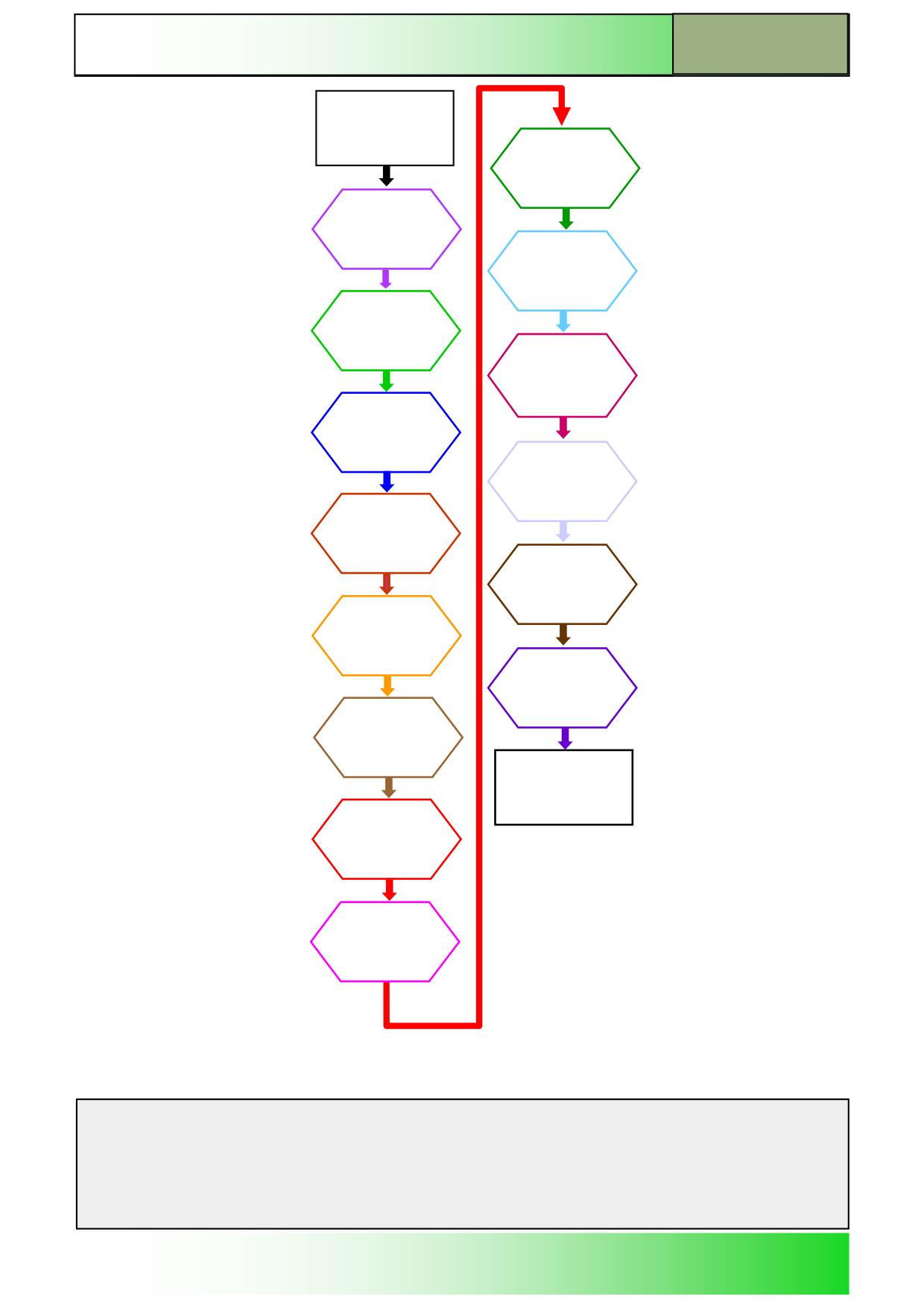
Drawings of programming examples
M701
Drawings of
programming
examples:
START
Bowling Pin
Bolt_1
Core
Bolt_2
Kidney
Shaft_1
Fixed Shaft
Spigot_1
Example
Counter
Spindle
Pin
Hub
Stepped
shaft
Drawings of
programming
examples:
END
Contour
spigot
Joint shaft
Notes
828D/840Dsl SINUMERIK Operate
Page 3
M701
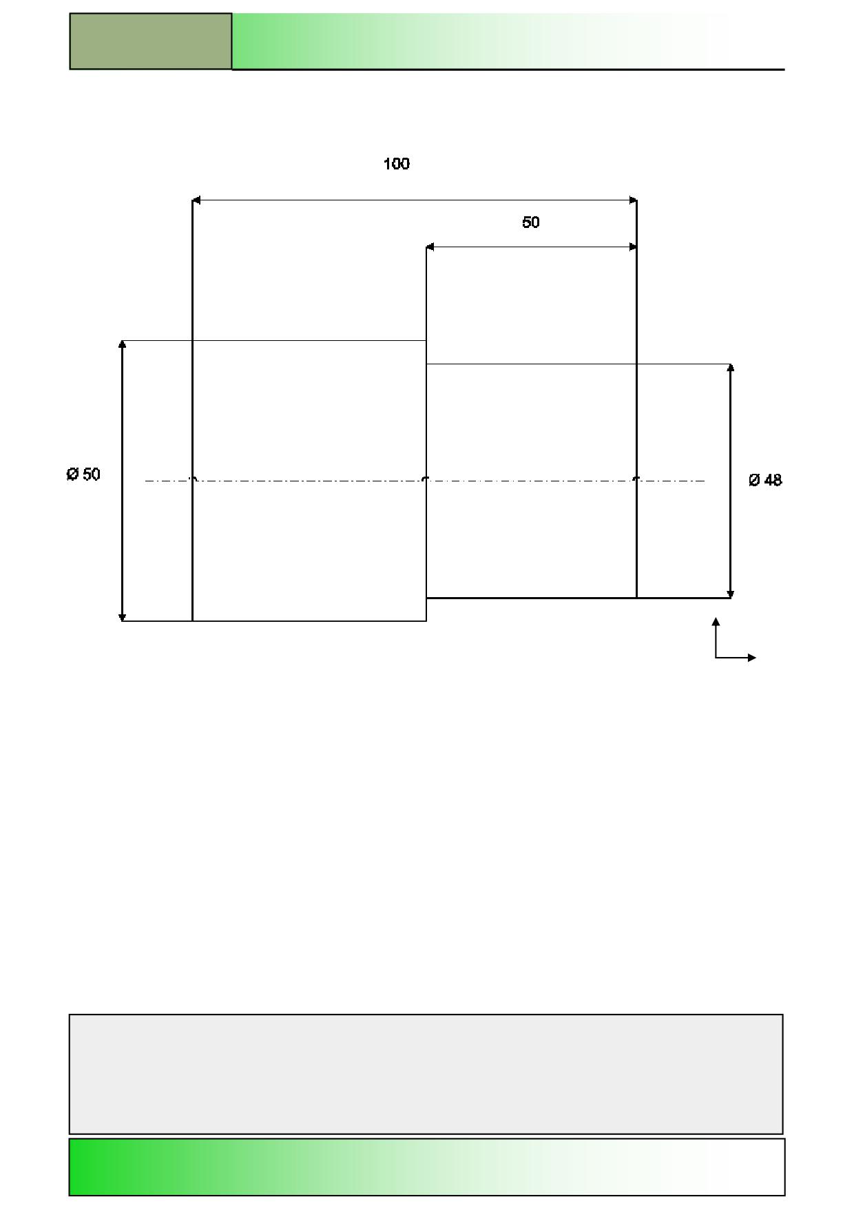
M701
Drawings of programming examples
Bolt_1
X
Z
Notes
M701
Page 4
828D/840Dsl SINUMERIK Operate
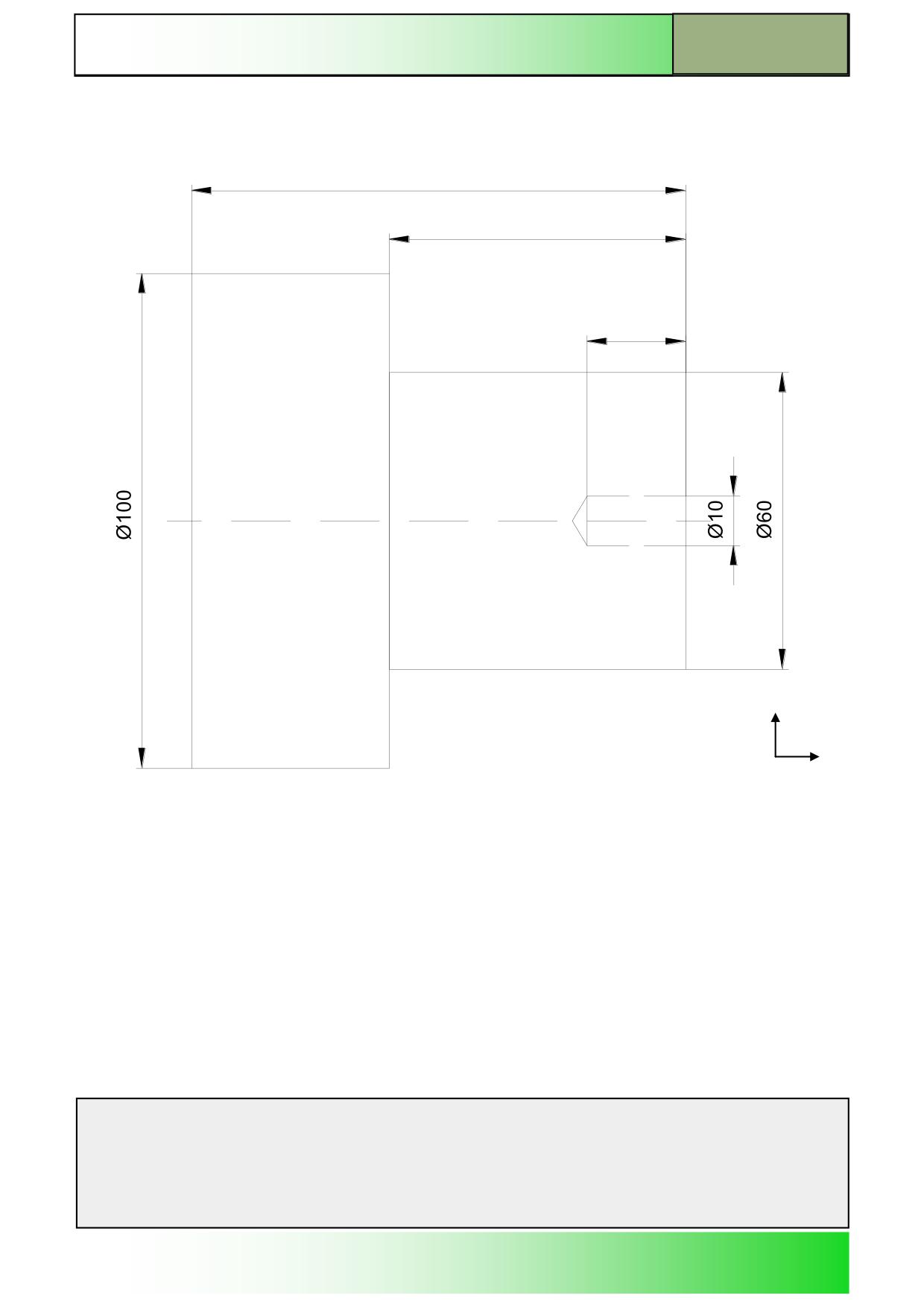
Drawings of programming examples
M701
Bolt_2
100
60
20
X
Z
Notes
828D/840Dsl SINUMERIK Operate
Page 5
M701
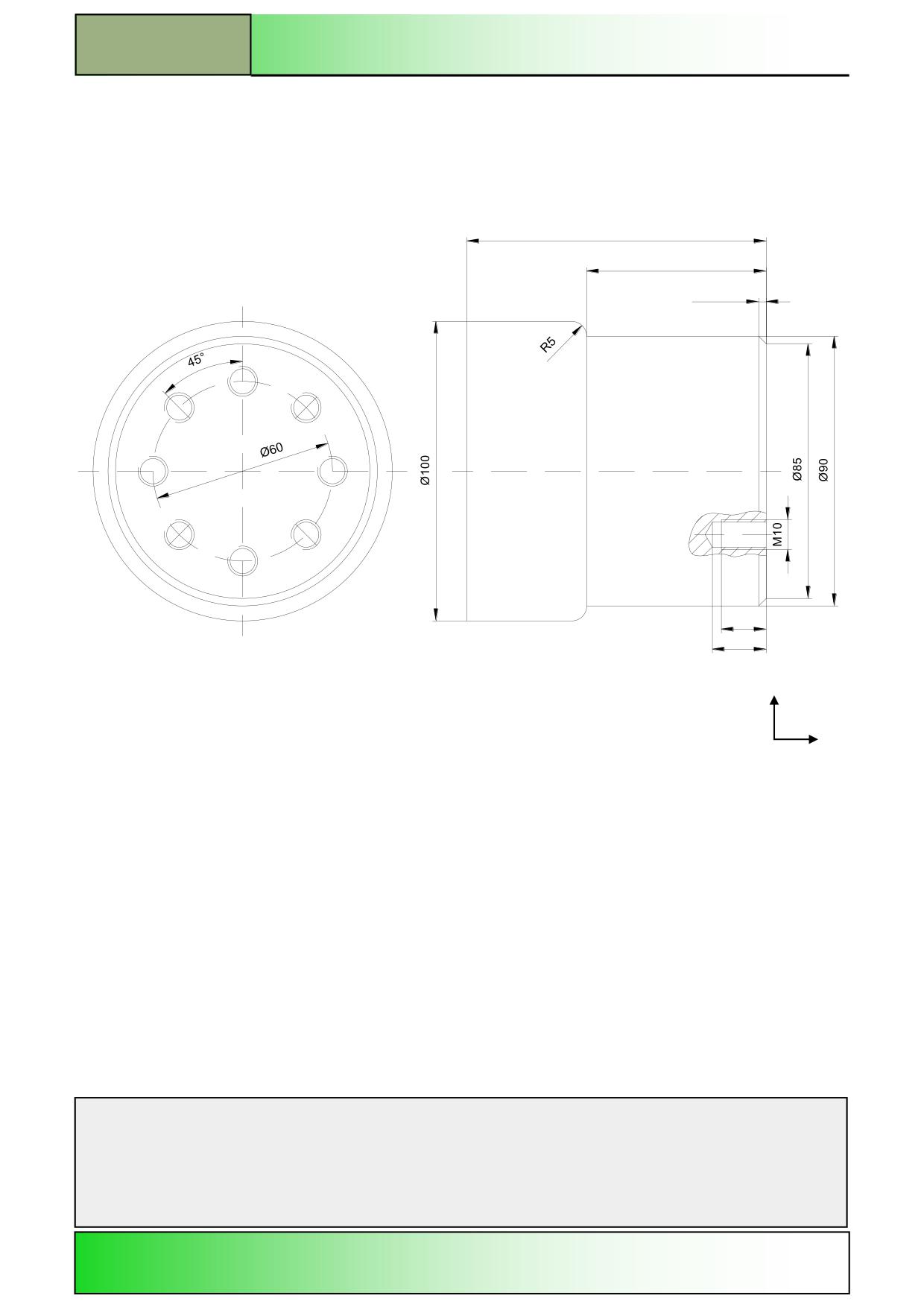
M701
Drawings of programming examples
Shaft_1
100
60
3x45°
15
18
X
Z
Notes
M701
Page 6
828D/840Dsl SINUMERIK Operate
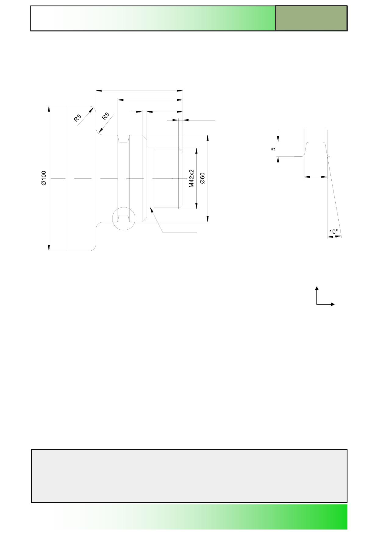
Drawings of programming examples
M701
Spigot_1
60
45
3x45°
25
3x45°
Detail X
8
All not-dimensioned Radii: 1 mm
DIN76
X
X
Z
Notes
828D/840Dsl SINUMERIK Operate
Page 7
M701
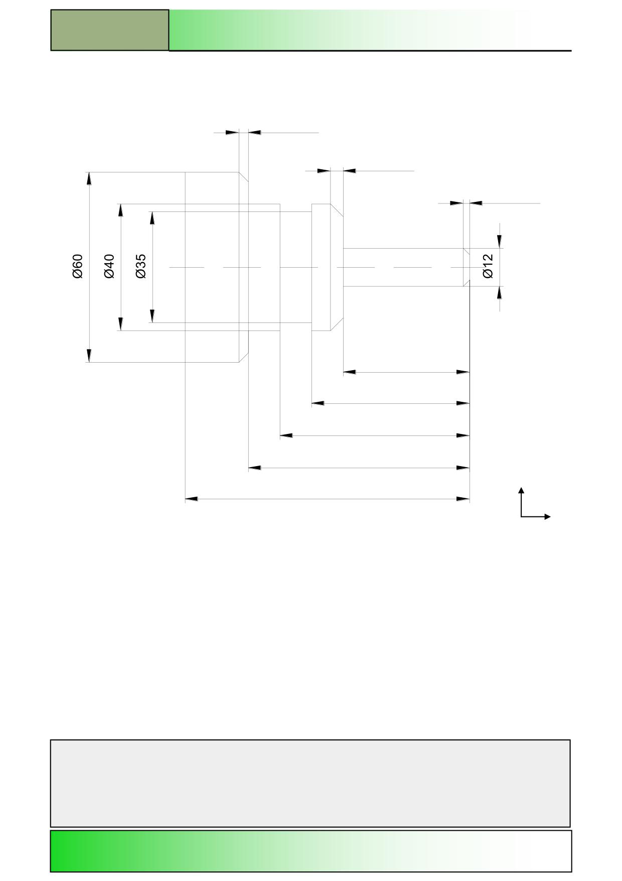
M701
Drawings of programming examples
Pin
3x45°
4x45°
2x45°
40
50
60
70
90
X
Z
Notes
M701
Page 8
828D/840Dsl SINUMERIK Operate
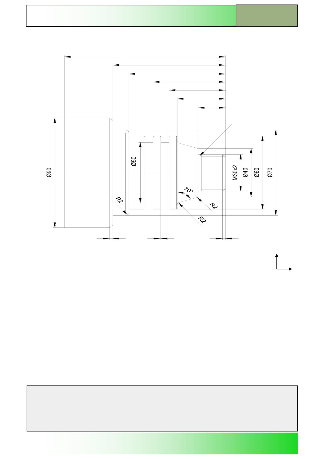
Drawings of programming examples
M701
Stepped shaft
100
70
60
45
35
30
17
DIN76
2x45°
0,5x45°
2x45°
X
Z
Notes
828D/840Dsl SINUMERIK Operate
Page 9
M701
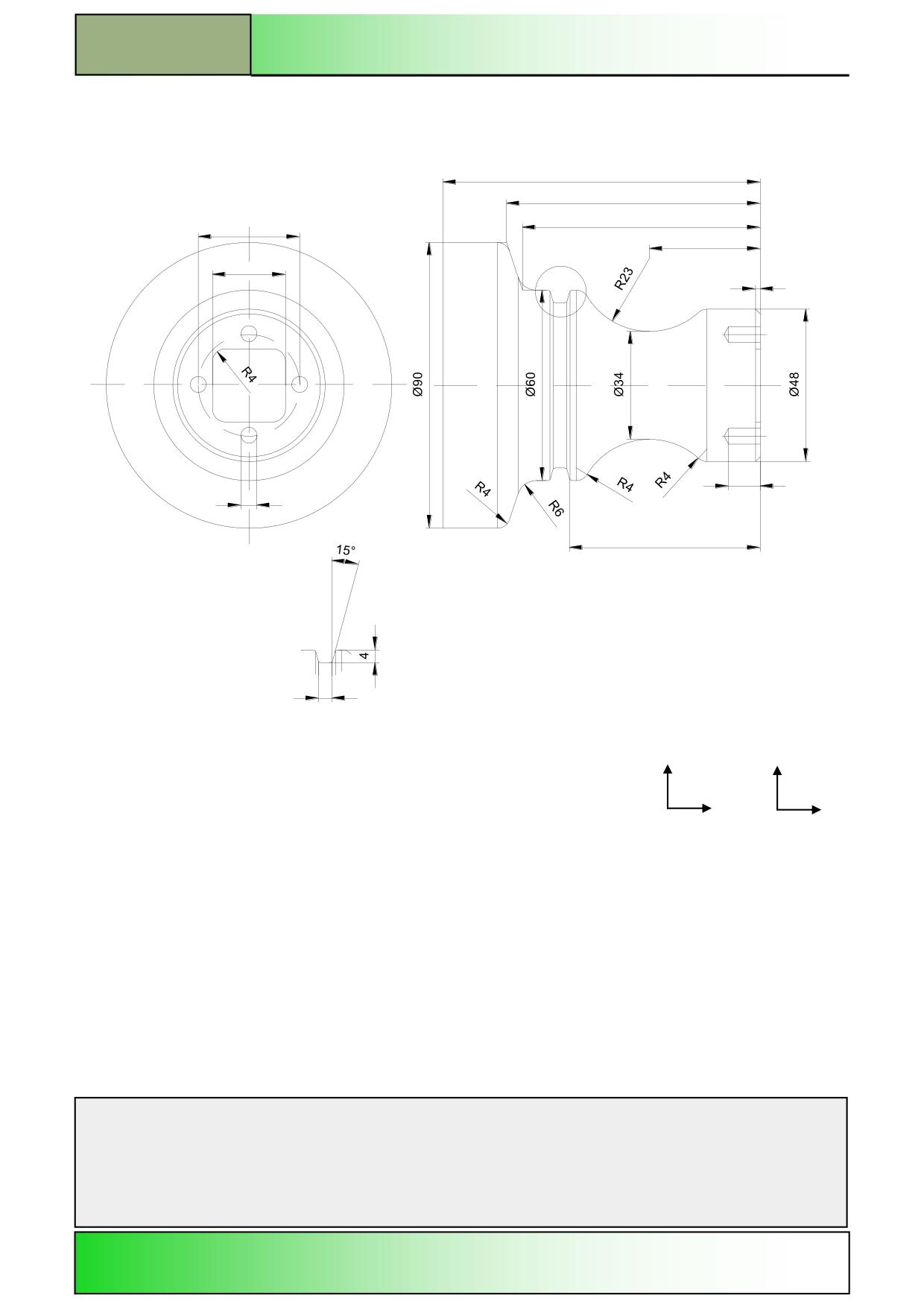
M701
Drawings of programming examples
Contour spigot
100
80
75
Ø32
35
X
23
2x45°
t=3
10
Ø5
60
X
All not-dimensioned Radii:
4,2
R=1
Y
X
X
Z
Notes
M701
Page 10
828D/840Dsl SINUMERIK Operate
Drawings of programming examples
M701
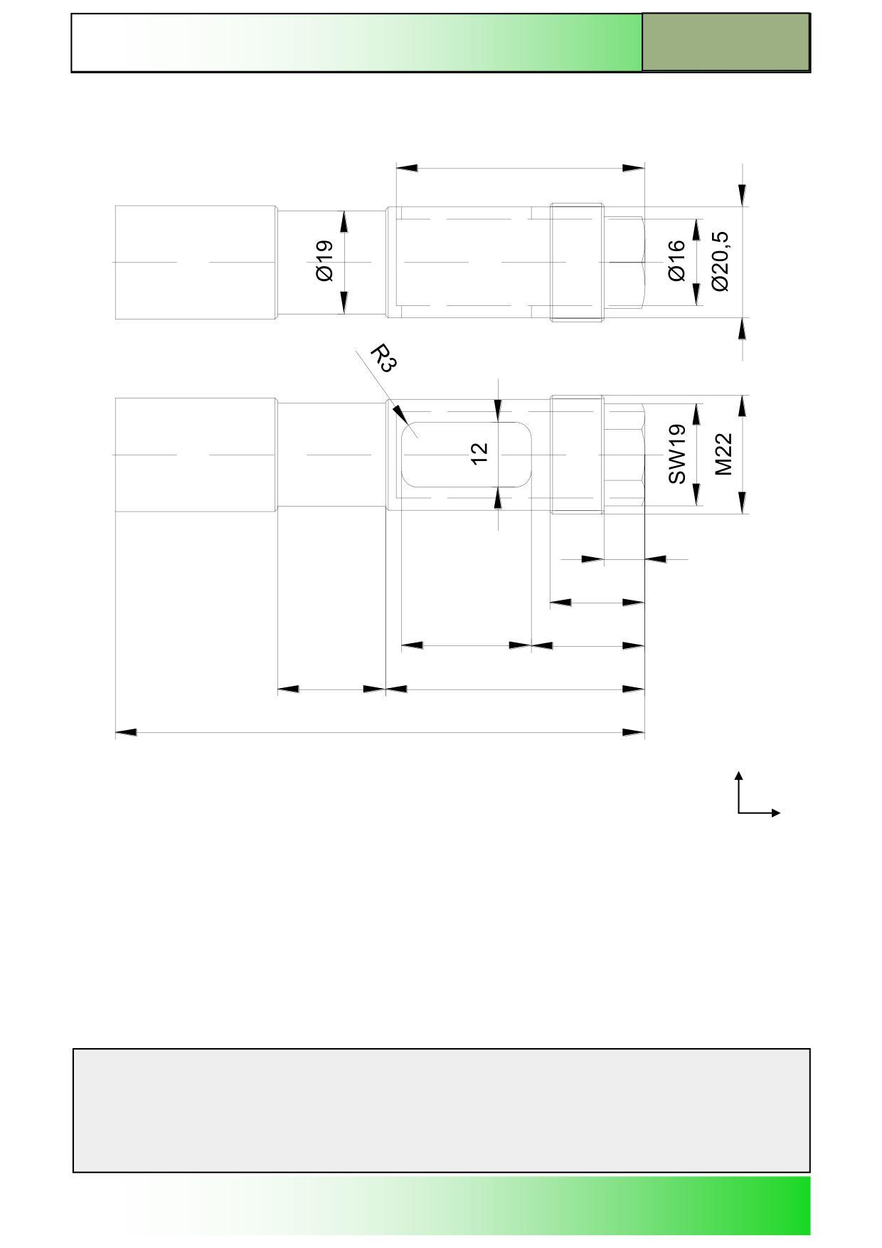
Joint shaft
46
8
18
24
21
20
48
98
X
Z
Notes
828D/840Dsl SINUMERIK Operate
Page 11
M701
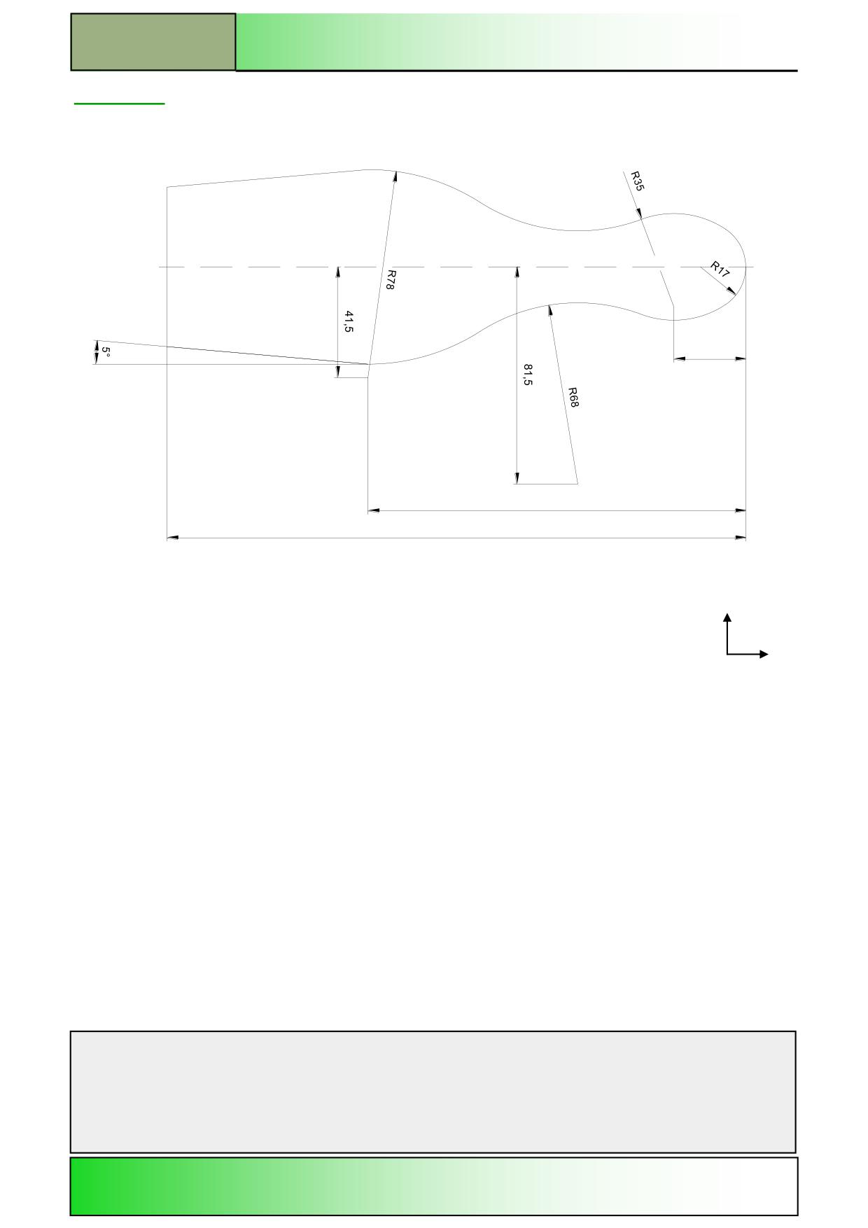
26,95
141,618
217
X
Z
Notes
M701
Page 12
828D/840Dsl SINUMERIK Operate
Drawings of programming examples
M701
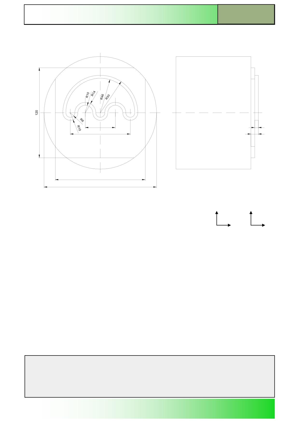
Core
t=3
40
5
80
10
120
Ø150
Y
X
X
Z
Notes
828D/840Dsl SINUMERIK Operate
Page 13
M701
M701
Drawings of programming examples
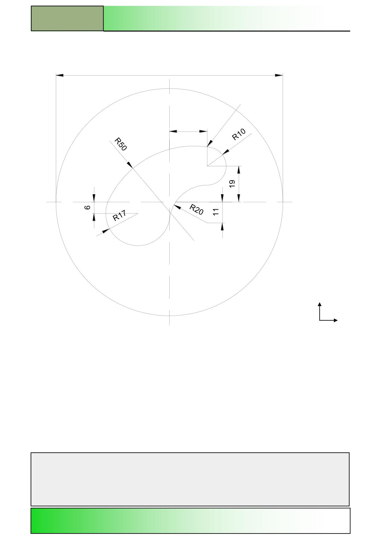
Kidney
Ø120
Startpoint
20
t=5
Y
X
Notes
M701
Page 14
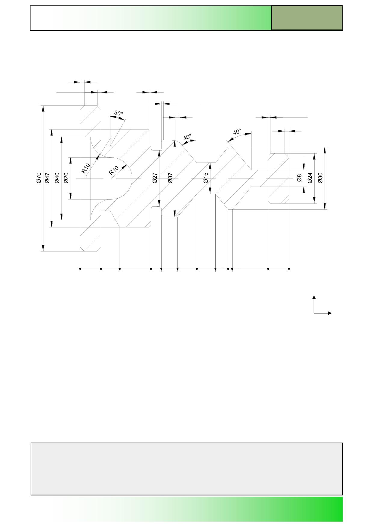
828D/840Dsl SINUMERIK Operate
Drawings of programming examples
M701
Fitting shaft
2x45°
2x45°
1x45°
1x45°
2x45°
1x45°
2x45°
10
9
15
5
8
9
9
6
2
17
10
X
Z
Notes
828D/840Dsl SINUMERIK Operate
Page 15
M701
M701
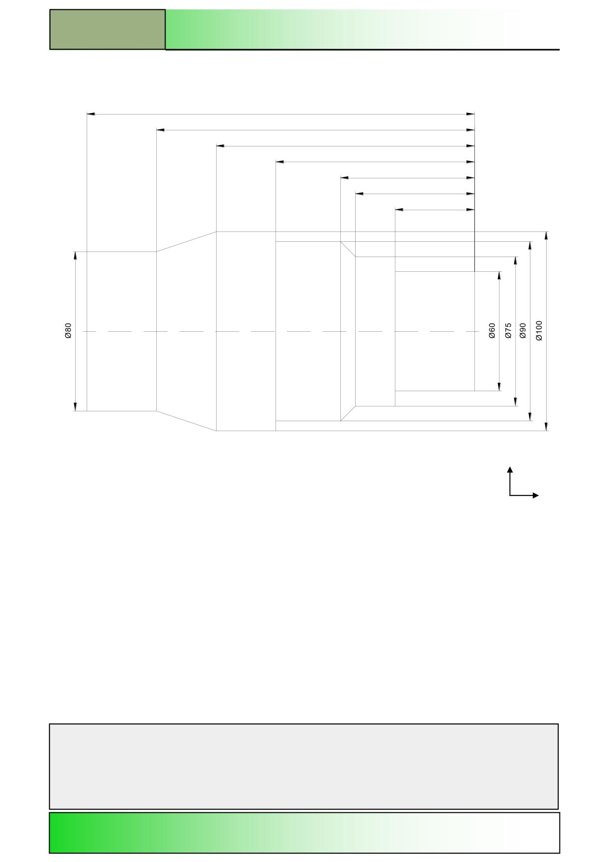
Drawings of programming examples
Example counter spindle
195
160
130
100
67,5
60
40
X
Z
Notes
M701
Page 16
828D/840Dsl SINUMERIK Operate
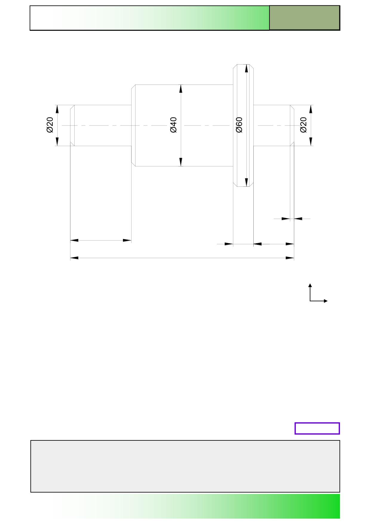
Drawings of programming examples
M701
Hub
2x45°
30
10
20
110
X
Z
M701: END
Notes
828D/840Dsl SINUMERIK Operate
Page 17
M701

y with ShopTurn
1
Introduction__________
2
ShopTurn
3
smoothly
SINUMERIK Operate
4
Basics for beginners_____
SinuTrain
5
Well equipped________
Turning made easy with ShopTurn
6
Example 1: Taper shaft____
Training Documents
7
Example 2: Input shaft ____
8
Example 3: Guide shaft____
9
Example 4: Hollow shaft___
10
Example 5: Plunge-turning __
And now you can start
11
manufacturing!________
How accomplished are you__
12
n the use of ShopTurn?
09/2011
6FC5095-0AB80-1BP1
Table of contents
1
Introduction
7
2
Advantages of working with ShopTurn
9
2.1
You will save time for training
9
2.2
You will save time for programming
11
2.3
You will save time for manufacturing
14
3
Ensuring everything runs smoothly
17
3.1
Using ShopTurn
17
3.2
The contents of the main menu
19
3.2.1
Machine
19
3.2.2
Parameters
22
3.2.3
Program
24
3.2.4
Program Manager
27
3.2.5
Diagnosis
29
4
Basics for beginners
31
4.1
Geometrical basics
31
4.1.1
Tool axes and work planes
31
4.1.2
Points in the work space
31
4.1.3
Absolute and incremental dimensioning
32
4.1.4
Cartesian and polar dimensions
34
4.1.5
Circular motions
36
4.2
Technological basics
38
4.2.1
Cutting rate and speeds
38
4.2.2
Feed
39
5
Well equipped
41
5.1
Tool management
41
5.1.1
The tool list
41
5.1.2
The tool wear list
43
5.1.3
Magazine list
44
5.2
Tools used
44
5.3
Tools in the magazine
46
5.4
Gauging tools
47
5.5
Setting the workpiece zero
49
6
Example 1: Taper shaft
51
6.1
Overview
51
6.2
Program management / creating programs
53
6.3
Calling a tool
57
Turning made easy with ShopTurn
Training Documents, 09/2011, 6FC5095-0AB80-1BP1
3
Table of contents
6.4
Specifying the distance to be traversed
59
6.5
Creating contours with the contour calculator and machining sequence
63
6.6
Thread undercut
79
6.7
Thread
82
6.8
Grooves
84
7
Example 2: Input shaft
89
7.1
Overview
89
7.2
Face turning
90
7.3
Creating the contour, stock removal and residual stock removal
91
7.4
Thread
110
8
Example 3: Guide shaft
113
8.1
Overview
113
8.2
Face turning
114
8.3
Creating any blank contour
116
8.4
Creating the machined part contour and stock removal
118
8.5
Residual stock removal
128
8.6
Groove
133
8.7
Thread
136
8.8
Drilling
138
8.9
Milling the rectangular pocket
143
9
Example 4: Hollow shaft
147
9.1
Overview
147
9.2
Creating the first workpiece side
148
9.2.1
Face turning
149
9.2.2
Drilling
150
9.2.3
Blank contour
152
9.2.4
Machined part contour of the first side, external
153
9.2.5
Undercut
164
9.2.6
Machined part contour of the first side, internal
168
9.2.7
The work step editor
174
9.2.8
Copying the contour
175
9.3
Creating the second workpiece side
176
9.3.1
Face turning
176
9.3.2
Drilling
178
9.3.3
Specifying a blank contour
180
9.3.4
Machined part contour of the second side, external
181
9.3.5
Creating an asymmetrical groove
185
9.3.6
Machined part contour of the second side, internal
188
Turning made easy with ShopTurn
4
Training Documents, 09/2011, 6FC5095-0AB80-1BP1
Table of contents
10
Example 5: Plunge-turning
195
10.1
Overview
195
10.2
Plunge-turning
196
10.3
Creating the contour
197
10.4
Stock removal with the plunge-turning cycle
198
11
And now you can start manufacturing!
203
11.1
And now you can start manufacturing!
203
12
How accomplished are you in the use of ShopTurn?
207
12.1
Exercise 1
207
12.2
Exercise 2
209
12.3
Exercise 3
211
12.4
Exercise 4
213
Index
217
Turning made easy with ShopTurn
Training Documents, 09/2011, 6FC5095-0AB80-1BP1
5
Introduction
1
Faster from the drawing to the workpiece - but how?
The technological development of machine tools is highly dynamic. Particularly with the
creation of NC programs, the range has extended from pure CAM system programming to
programming directly at the CNC machine. Special, productive programming methods are
available for each area. With ShopTurn, SIEMENS therefore offers a programming method
specially tailored to the shop floor which allows quick and practical programming of
machining steps from the manufacture of single parts up to small batches. In conjunction
with SINUMERIK Operate, the new operator interface for the control system, intuitive and
effective working in the workshop is possible even for series production.
The solution is: Creating a process plan instead of programming
The creation of a process plan with intuitive and operator-friendly handling sequences,
allows the ShopTurn user to create the NC program directly from the drawing. Even changes
and different variants of a workpiece can be quickly programmed due to the clear structure.
Even the most complicated contours and workpieces are simple to manufacture with
ShopTurn thanks to the integrated, powerful tools for creating traversing paths. For this
reason:
Simpler and faster from the drawing to the workpiece - with ShopTurn.
Although ShopTurn is easy to learn, these ShopTurn Training Documents allow you to enter
this world even faster. Before, however, it comes to actually working with ShopTurn, the first
sections cover a few important basics:
● First, we will show you the advantages of working with ShopTurn.
● Then, we will explain the basics of the operation.
● And next, the geometrical and technological fundamentals will be introduced to the
beginner.
● A short introduction to tool management will be given in a further section.
The theory is followed by practical exercises with ShopTurn:
● Five examples have been chosen to explain the machining possibilities with ShopTurn,
whereby the degree of difficulty is increased continuously. At the beginning, all key
actions are specified; later you will be prompted to proceed without help.
● Then you will learn how to cut in AUTOMATIC mode using ShopTurn.
● If you wish, at the end you may test your knowledge of ShopTurn.
Turning made easy with ShopTurn
Training Documents, 09/2011, 6FC5095-0AB80-1BP1
7
Introduction
Please note that the technology data used here are only examples due to the wide variety of
situations in the workshop.
Just as ShopTurn itself was created with the help of skilled workers, these Training
Documents were also drawn up by practical users. On that note, we wish you much pleasure
and success in your work with ShopTurn.
Turning made easy with ShopTurn
8
Training Documents, 09/2011, 6FC5095-0AB80-1BP1
Advantages of working with ShopTurn
2
This section shows you the special advantages of working with ShopTurn.
2.1
You will save time for training
● ShopTurn does not use any foreign-language terms you would otherwise have to learn.
All required inputs are requested in plain text.
● When working with ShopTurn, you are offered clear assistance by colored help displays.
Turning made easy with ShopTurn
Training Documents, 09/2011, 6FC5095-0AB80-1BP1
9
Advantages of working with ShopTurn
2.1 You will save time for training
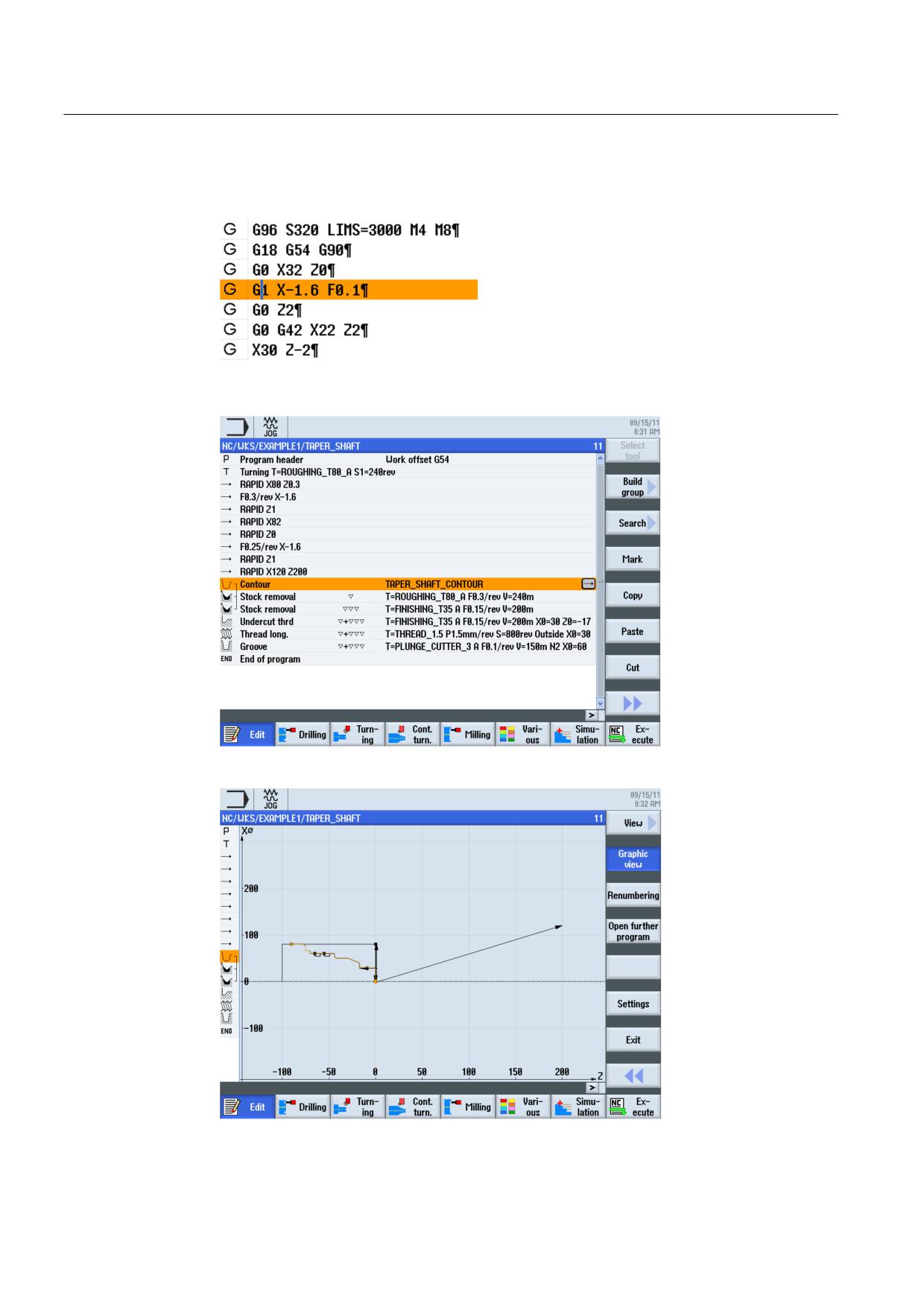
● You can also integrate DIN/ISO commands into the Graphical Process Plan of ShopTurn.
You may also program in DIN/ISO 66025 and use DIN cycles.
● You may switch between the individual work step and the workpiece graphic (broken-line
graphics) at any time during the creation of a process plan.
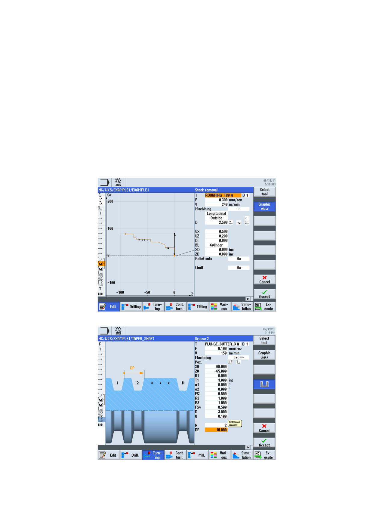
Figure 2-1
Work step in a process plan
Figure 2-2
Broken-line graphics
Turning made easy with ShopTurn
10
Training Documents, 09/2011, 6FC5095-0AB80-1BP1
Advantages of working with ShopTurn
2.2 You will save time for programming...
2.2
You will save time for programming...
● ShopTurn offers optimum assistance when it comes to entering technological values: You
only have to enter the handbook values feedrate (or feed) and cutting rate - the speed is
calculated by ShopTurn automatically.
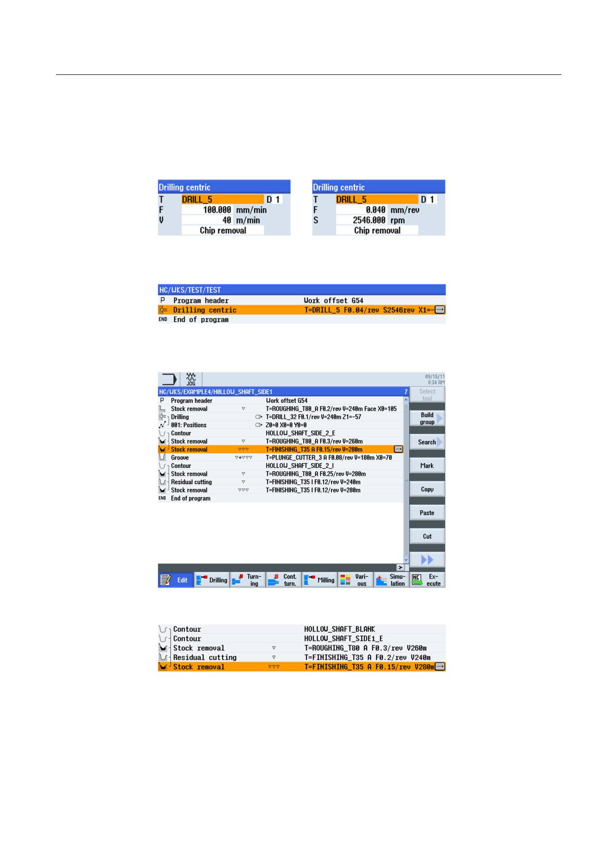
● ShopTurn enables you to describe a complete machining sequence using only one work
step, and the required positioning motions (in this case, from the tool change point to the
workpiece and back) are created automatically.
● All work steps are represented by ShopTurn in a compact and clear fashion in the
Graphical Process Plan. This provides you a complete overview and thus better editing
possibilities even if comprehensive manufacturing sequences are to be performed.
● During stock removal, for example, several machining operations and contours can be
linked together.
Turning made easy with ShopTurn
Training Documents, 09/2011, 6FC5095-0AB80-1BP1
11
Advantages of working with ShopTurn
2.2 You will save time for programming...
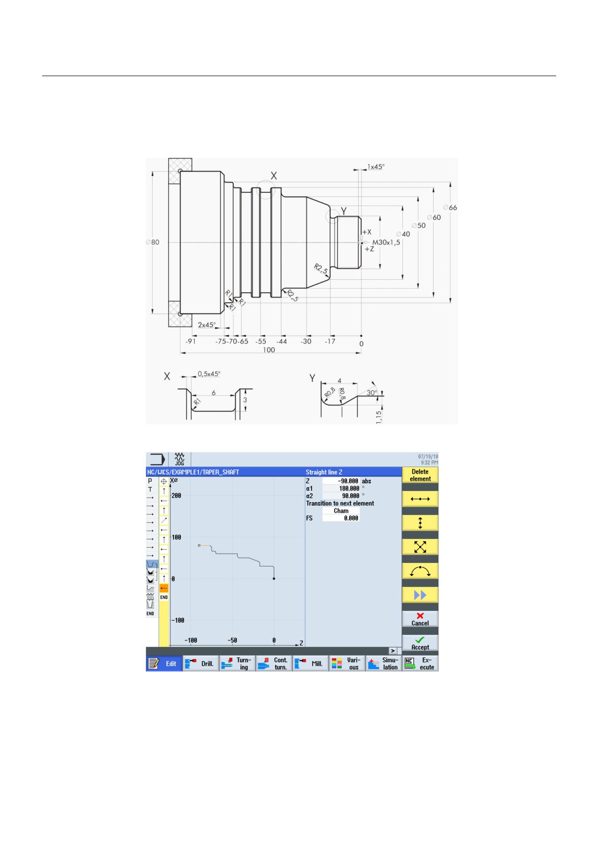
● The integrated contour calculator can process all standard dimensions (Cartesian, polar);
it is nevertheless very easy to handle and understand - thanks to colloquial input and
graphic support.
Figure 2-3
Technical drawing
Figure 2-4
Screenform
Turning made easy with ShopTurn
12
Training Documents, 09/2011, 6FC5095-0AB80-1BP1
Advantages of working with ShopTurn
2.2 You will save time for programming...
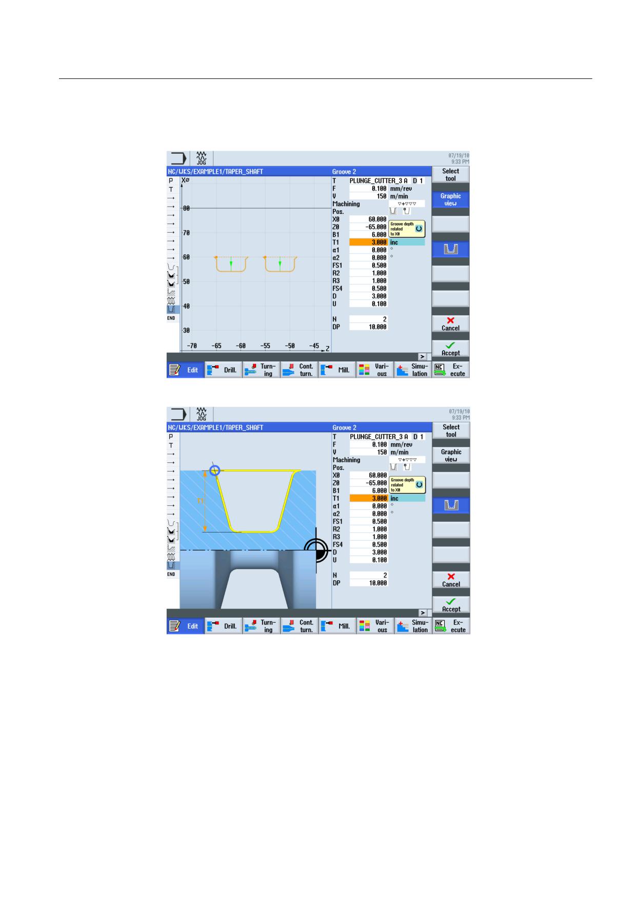
● You may switch between the graphic view and parameter screenform with help display at
any time.
Figure 2-5
Graphic view
Figure 2-6
Help display
● Process plan and manufacturing do not exclude each other. With ShopTurn, you can
create a new process plan parallel to manufacturing.
Turning made easy with ShopTurn
Training Documents, 09/2011, 6FC5095-0AB80-1BP1
13
Advantages of working with ShopTurn
2.3 You will save time for manufacturing...
2.3
You will save time for manufacturing...
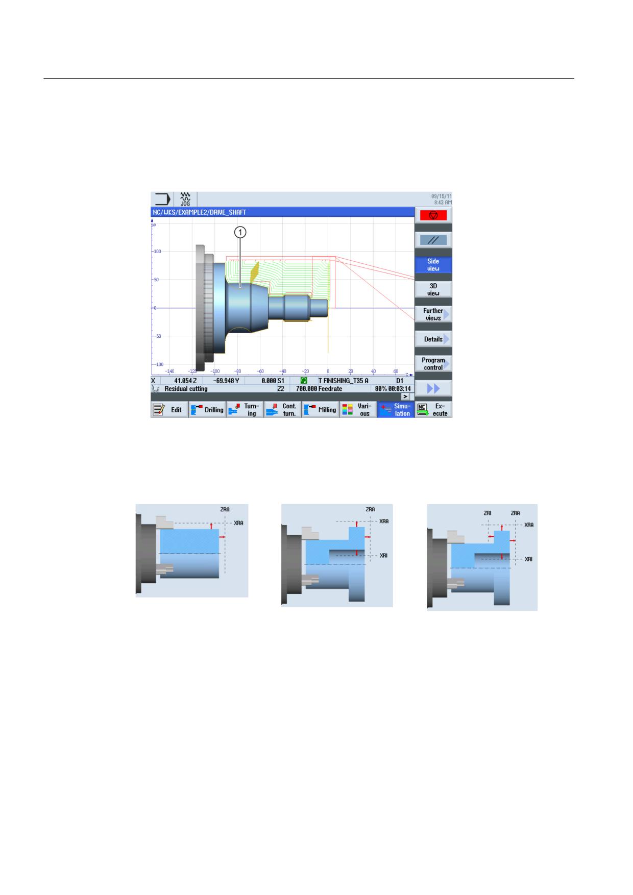
● You can optimize tool selection during the stock removal of contours:
Large volumes are removed using roughing tools, any residual material ① is then
detected and removed automatically using a pointed tool.
● The exact specification of the selected retraction plane avoids the use of unnecessary
traversing paths and thereby saves valuable manufacturing time. This is possible using
the settings normal, extended and all.
Retraction plane: normal
Retraction plane: extended
Retraction plane: all
Turning made easy with ShopTurn
14
Training Documents, 09/2011, 6FC5095-0AB80-1BP1
Advantages of working with ShopTurn
2.3 You will save time for manufacturing...
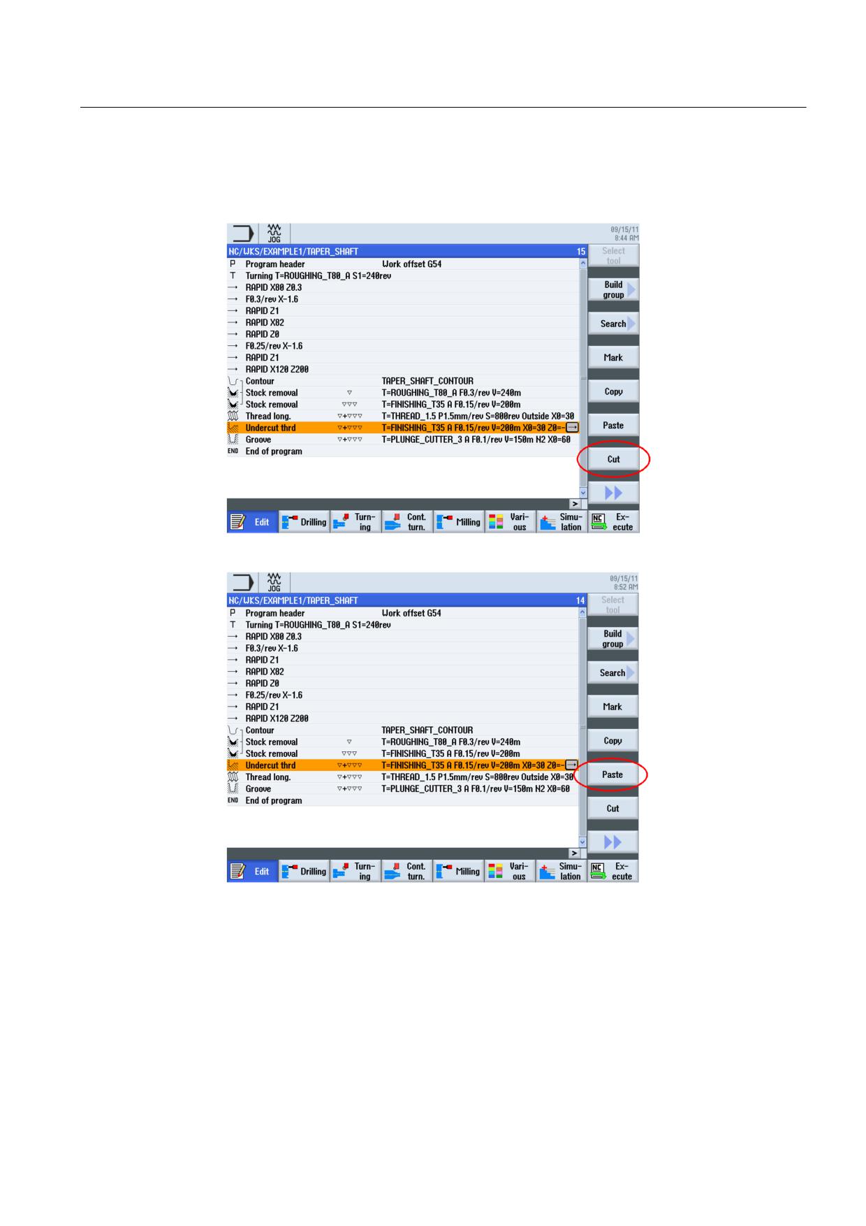
● You can optimize your machining sequence with a minimum of work - thanks to the
compact structure of the process plan (in this case, by saving of a tool change, for
example).
Figure 2-7
Original machining sequence
Figure 2-8
Optimized machining sequence with cutting and pasting
● With ShopTurn, you can achieve extremely high feedrates with optimum repeat accuracy
based on consistent digital technology (SINAMICS drives,
, SINUMERIK control
systems).
Turning made easy with ShopTurn
Training Documents, 09/2011, 6FC5095-0AB80-1BP1
15
Advantages of working with ShopTurn
2.3 You will save time for manufacturing...
Turning made easy with ShopTurn
16
Training Documents, 09/2011, 6FC5095-0AB80-1BP1
Ensuring everything runs smoothly
3
In this section you will learn the basics of ShopTurn operation with the help of examples.
3.1
Using ShopTurn
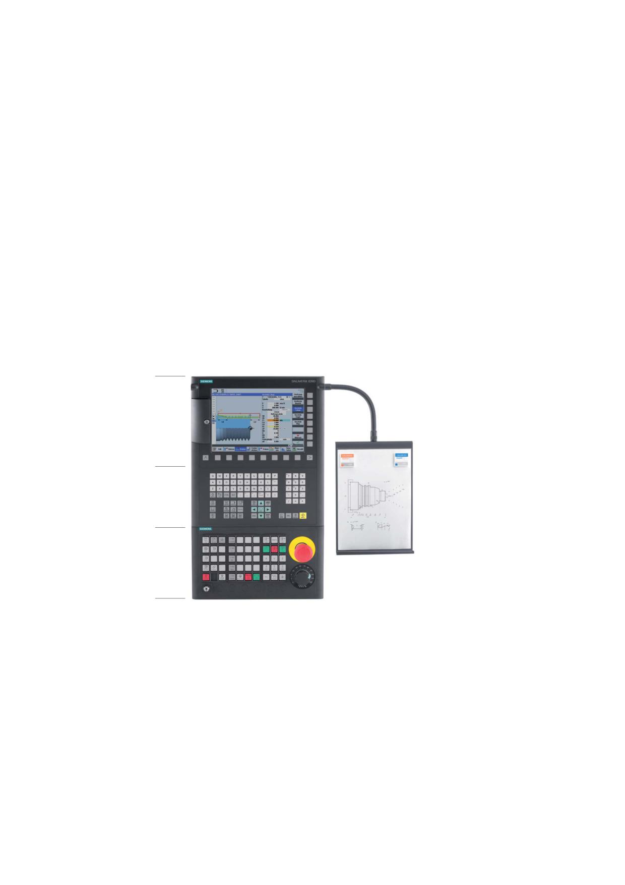
A powerful software is one thing, but it must also be easy to operate. Regardless of whether
you work with the SINUMERIK 840D sl or SINUMERIK 828D shown here - you are always
assisted by the clearly laid-out machine operator panel. The operator panel consists of 3
parts - the flat operator panel ①, the CNC full keyboard ② and the machine control panel
(MCP) ③.
ཱ
ི
Turning made easy with ShopTurn
Training Documents, 09/2011, 6FC5095-0AB80-1BP1
17
Ensuring everything runs smoothly
3.1 Using ShopTurn
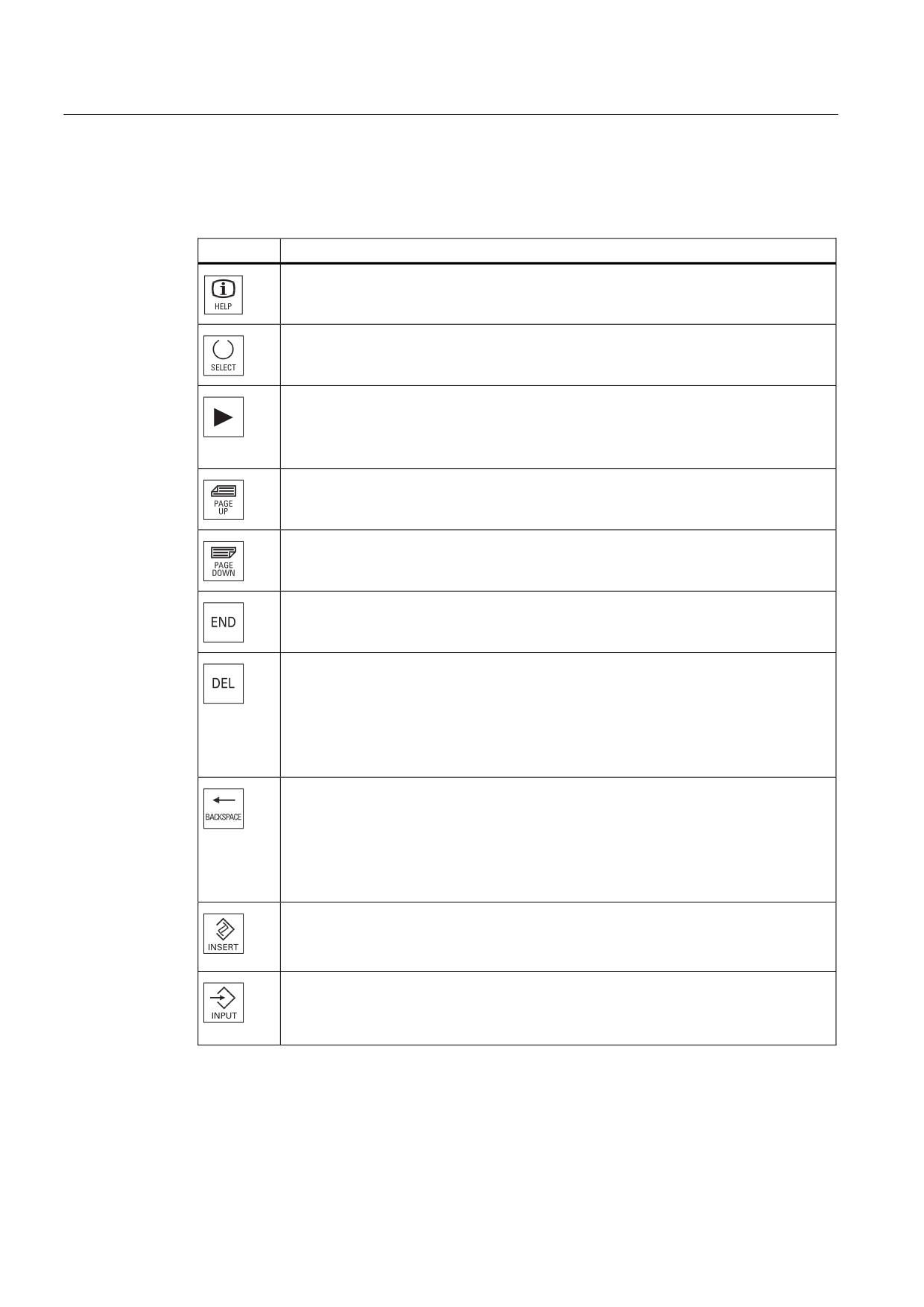
The most important keys on the CNC full keyboard for navigation in ShopTurn are listed in
the following:
Key
Function
<HELP>
Calls the context-sensitive online help for the selected window.
<SELECT>
Selects a listed value.
Cursor keys
The cursor is moved using the 4 cursor keys.
Use the <Cursor to the right> key to open a directory or program (e.g. a cycle) in the
editor.
<PAGE UP>
Scrolling upwards in a menu screen.
<PAGE DOWN>
Scrolling downwards in a menu screen.
<END>
Moves the cursor to the last input field in a menu screen or a table.
<DEL>
• Edit mode:
Deletes the first character to the right.
• Navigation mode:
Deletes all characters.
<BACKSPACE>
• Edit mode:
Deletes a character selected to the left of the cursor.
• Navigation mode:
Deletes all of the selected characters to the left of the cursor.
<INSERT>
• Pressing the <INSERT> key opens the "Editing" mode, and when you press the key
again, you will leave the "Editing" mode and you can call the "Navigation" mode.
<INPUT>
• Completes input of a value in the input field.
• Opens a directory or program.
The actual function selection in ShopTurn is performed using the keys located around the
screen. Most of them are assigned directly to the individual menu items. Since the contents
of the menus change depending on the situation, the term 'softkeys' is used.
Turning made easy with ShopTurn
18
Training Documents, 09/2011, 6FC5095-0AB80-1BP1
Ensuring everything runs smoothly
3.2 The contents of the main menu
All main functions can be called using the horizontal softkeys.
All subfunctions in ShopTurn can be called using the vertical softkeys.
The main menu can be called with this key at any time - irrespective of in which operating
area you are at the moment.
Main menu
3.2
The contents of the main menu
3.2.1
Machine
Machine - Manual
Select the "Machine" softkey.
Press the "JOG" key.
Turning made easy with ShopTurn
Training Documents, 09/2011, 6FC5095-0AB80-1BP1
19
Ensuring everything runs smoothly
3.2 The contents of the main menu
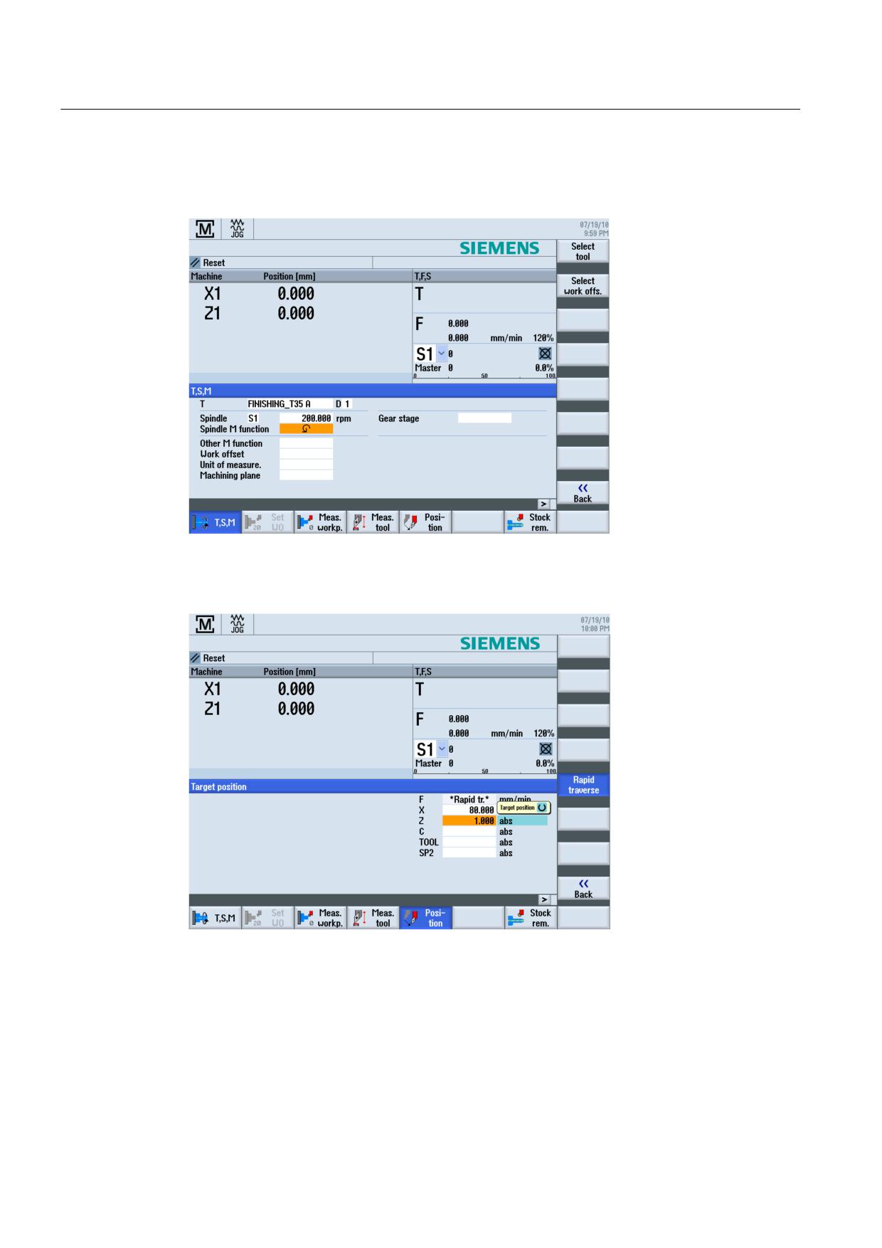
In this mode, the machine is set up; the tool is traversed in the MANUAL mode. It is also
possible to gauge tools and to set workpiece zeros.
Figure 3-1
Call of a tool and input of technological values
Figure 3-2
Input of a target position
Turning made easy with ShopTurn
20
Training Documents, 09/2011, 6FC5095-0AB80-1BP1
Ensuring everything runs smoothly
3.2 The contents of the main menu
Machine - AUTO
Select the "Machine" softkey.
Press the AUTO key.
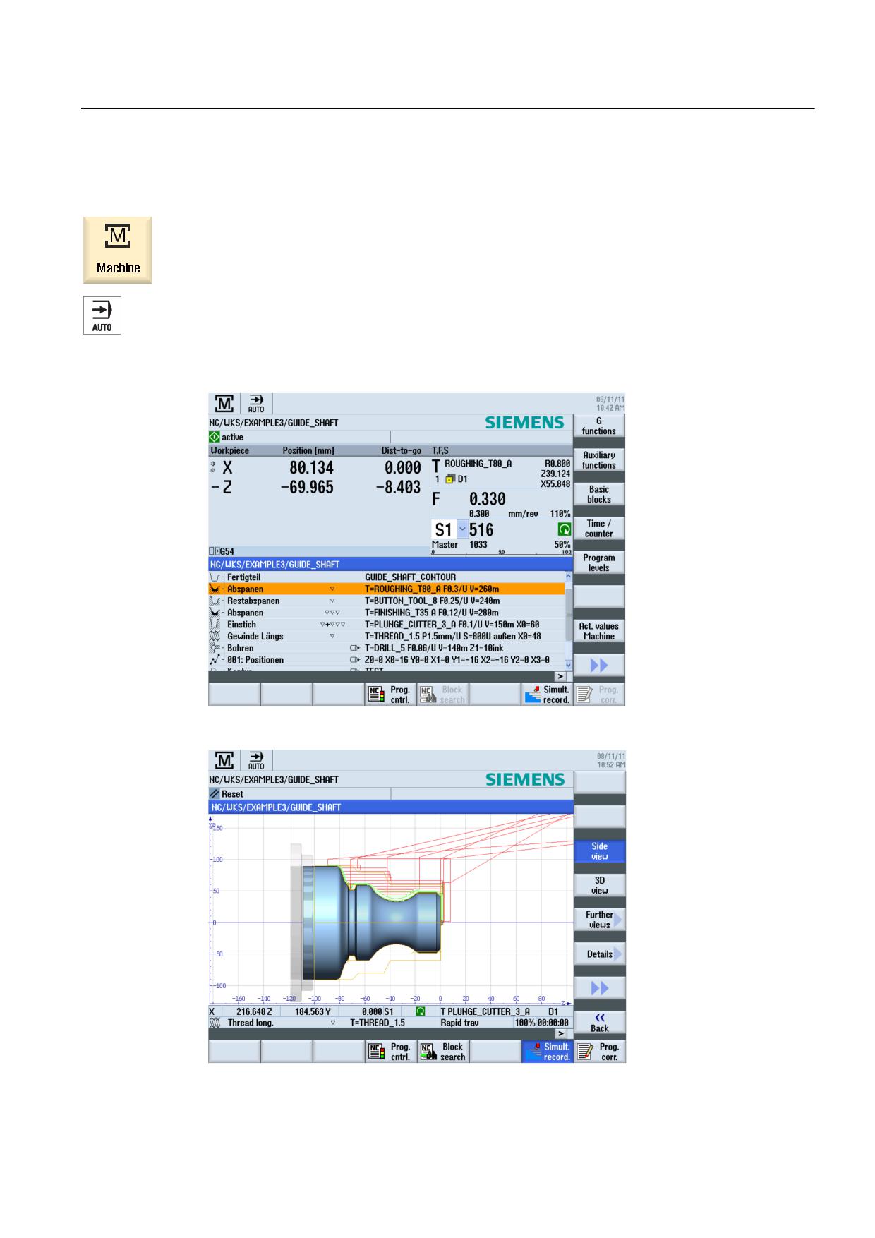
During manufacturing, the current work step is displayed. It is possible to switch to a running
simulation using the relevant key ("Drawing"). When executing a process plan, you may
insert work steps and/or create a new process plan.
Figure 3-3 Executing a process plan
Figure 3-4
Simultaneous recording of the execution
Turning made easy with ShopTurn
Training Documents, 09/2011, 6FC5095-0AB80-1BP1
21
Ensuring everything runs smoothly
3.2 The contents of the main menu
3.2.2
Parameters
Parameter lists
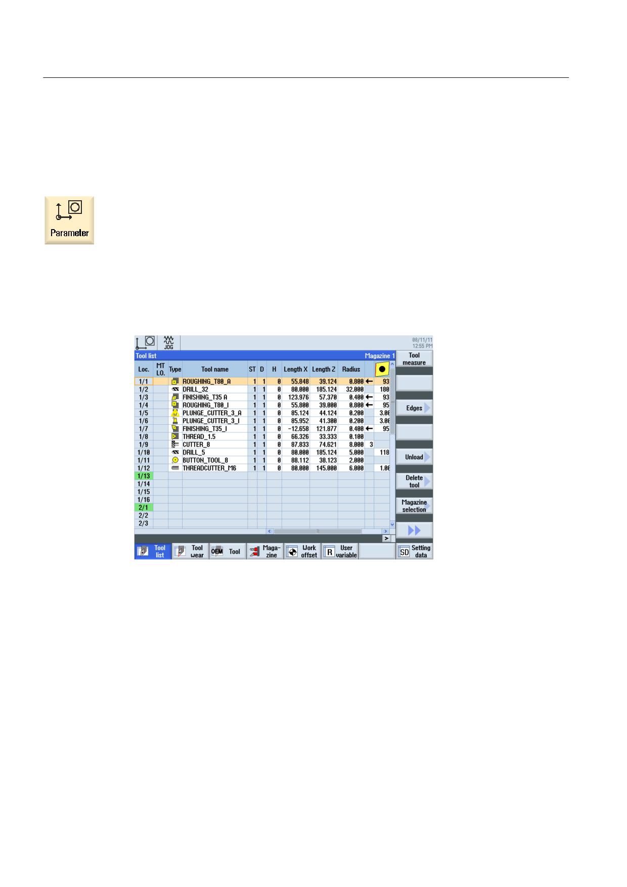
This key can be used to edit data for the tool management and for programs.
Tool lists
No cutting without tools.
The tools can be managed in a tool list.
Figure 3-5
Tool list
Turning made easy with ShopTurn
22
Training Documents, 09/2011, 6FC5095-0AB80-1BP1
Ensuring everything runs smoothly
3.2 The contents of the main menu
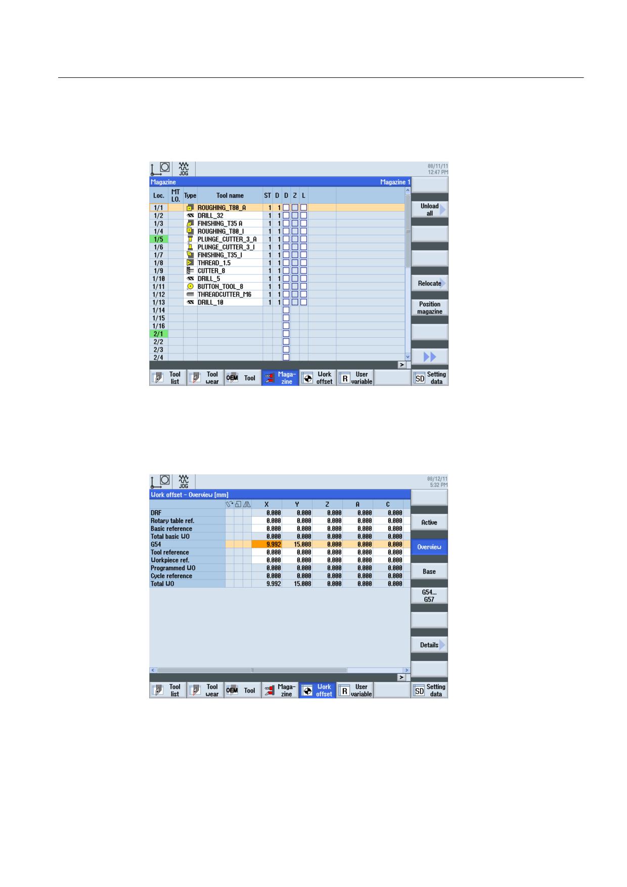
Magazine
Tools can be organized into a magazine.
Figure 3-6
Magazine
Work offsets
Zero points are saved in a clearly laid-out zero-point table.
Figure 3-7
Work offsets
Turning made easy with ShopTurn
Training Documents, 09/2011, 6FC5095-0AB80-1BP1
23
Ensuring everything runs smoothly
3.2 The contents of the main menu
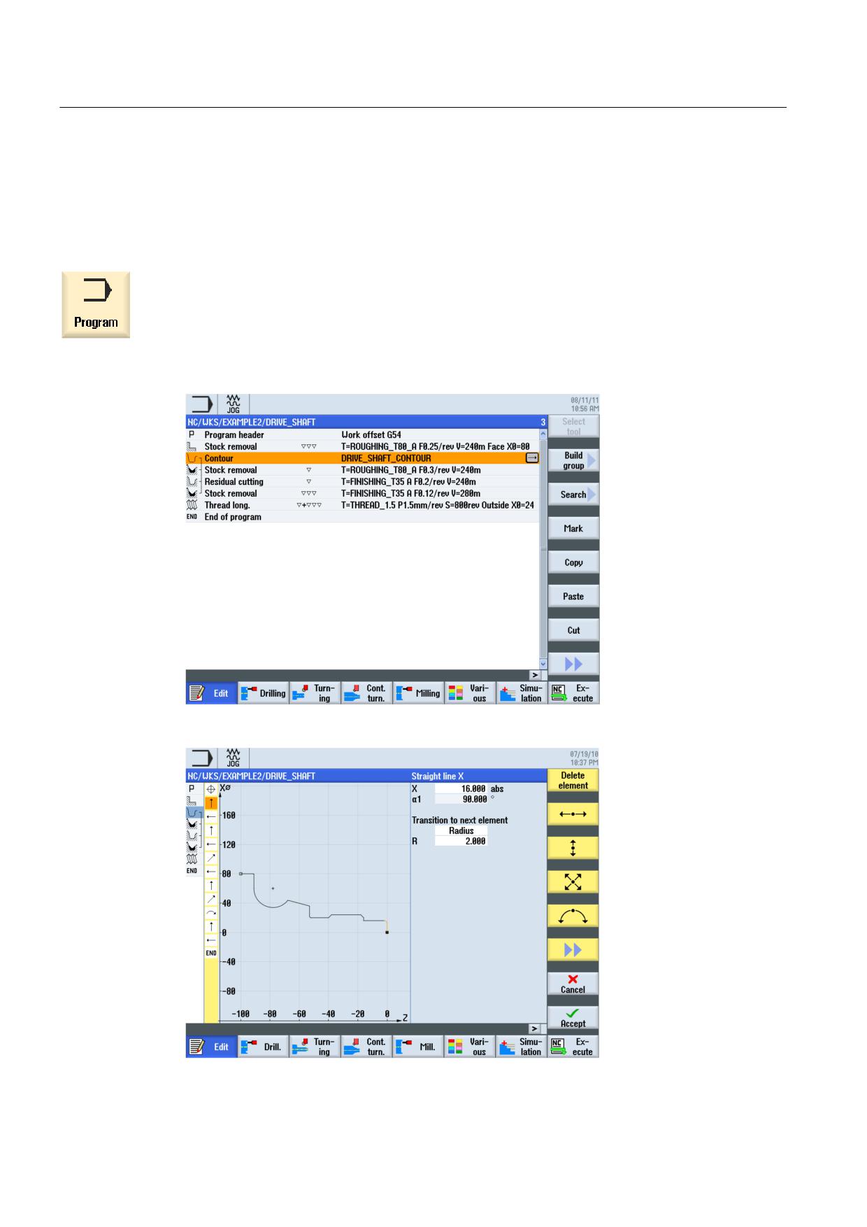
3.2.3
Program
Editing programs
This key can be used to edit programs.
If you have created a ShopTurn program in the Program Manager, you can now create the
process plan with the complete machining sequence for the appropriate workpiece. An
optimum sequence can only be achieved by a skilled worker with suitable experience.
The contour to be machined is entered graphically as a machining step.
Turning made easy with ShopTurn
24
Training Documents, 09/2011, 6FC5095-0AB80-1BP1
Ensuring everything runs smoothly
3.2 The contents of the main menu
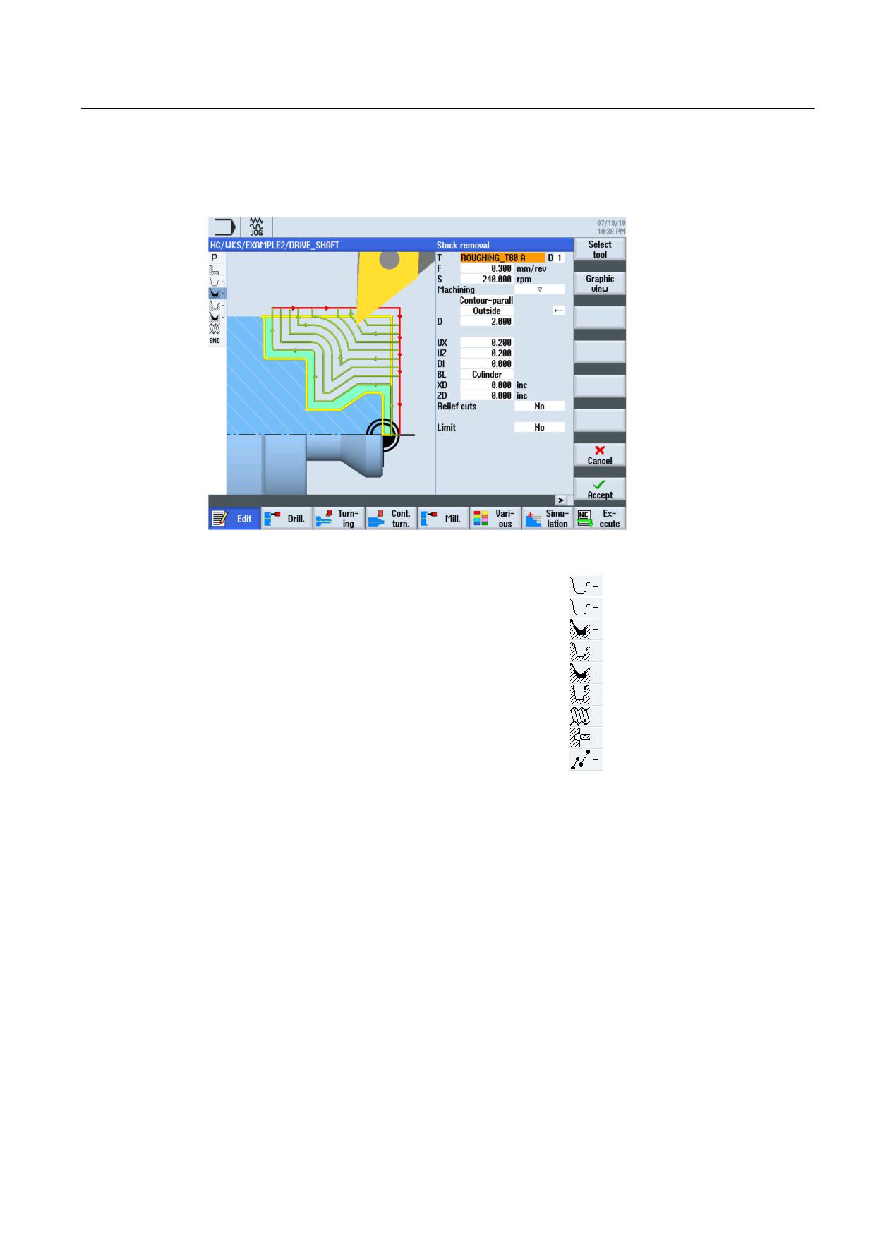
Geometry and technology constitute a unit in programming. The subsequent technological
machining operations are applied to the contour.
Example for the dovetailing of geometry and technology:
%ODQN FRQWRXU
0DFKLQHG SDUW FRQWRXU
6WRFN UHPRYDO URXJKLQJ LQFOXGLQJ DSSURDFK DQG UHWUDFW VWUDWHJLHV
5HVLGXDO VWRFN UHPRYDO
6WRFN UHPRYDO ILQLVKLQJ
*URRYH F\FOH
7KUHDG F\FOH
'ULOOLQJ F\FOH
'ULOOLQJ SRVLWLRQV
This geometrical-technological interrelation is represented very clearly in the graphical
display of the work steps by putting the appropriate symbols in brackets. The brackets mean
linking of geometry and technology to one work step.
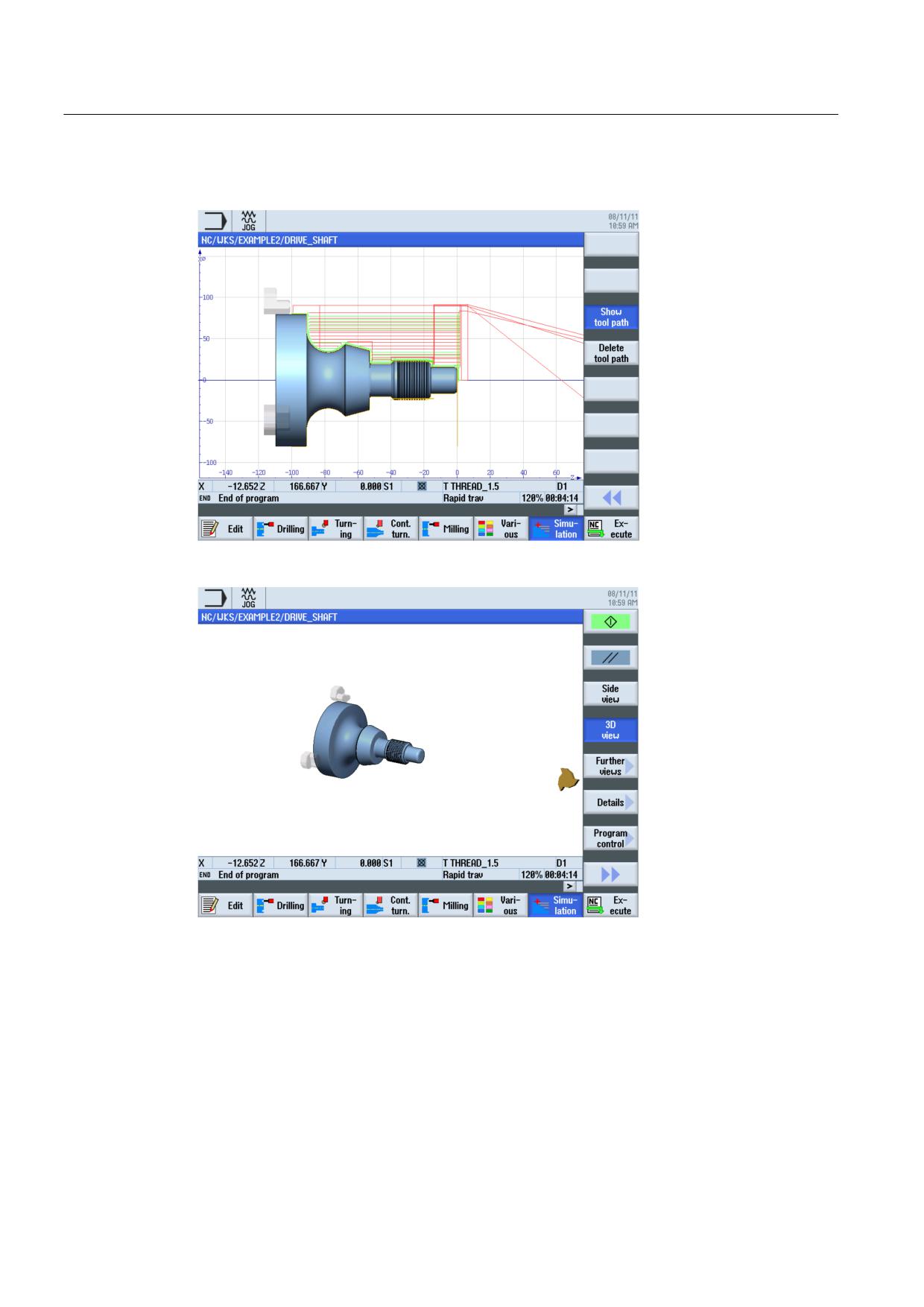
Simulating programs
Before machining a workpiece on the machine, it is possible to display the program
execution graphically on the screen.
● To this end, select the "Simulation" and "Start" softkeys.
● To stop simulation, select the "Stop" softkey.
● To cancel simulation, use the "Reset" softkey.
Turning made easy with ShopTurn
Training Documents, 09/2011, 6FC5095-0AB80-1BP1
25
Ensuring everything runs smoothly
3.2 The contents of the main menu
The following views are available, among others, for simulation:
Figure 3-8
Side view (display tool path, activated)
Figure 3-9
3D view
Turning made easy with ShopTurn
26
Training Documents, 09/2011, 6FC5095-0AB80-1BP1
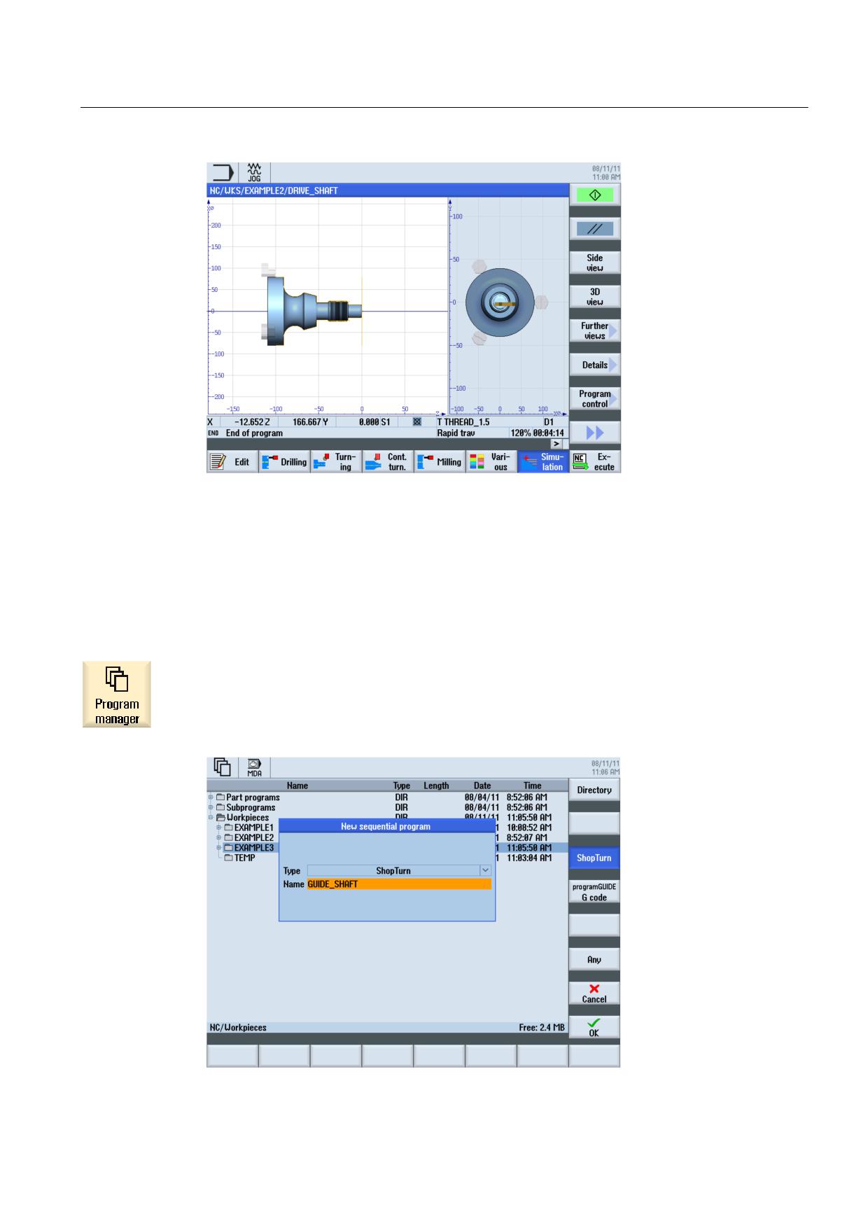
Ensuring everything runs smoothly
3.2 The contents of the main menu
Figure 3-10
2-window view
3.2.4
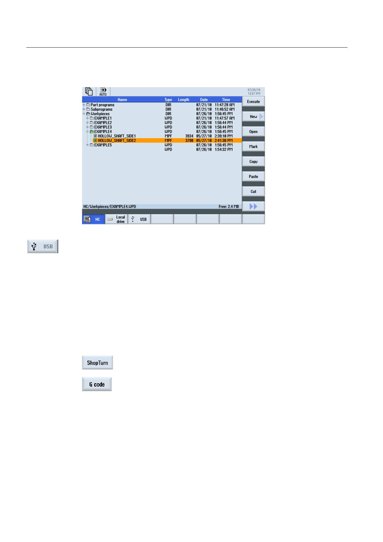
Program Manager
Managing programs
With the Program Manager, you can create new programs at any time. You can similarly
open existing programs to execute, modify, copy or rename them. Programs no longer
required can be deleted.
Turning made easy with ShopTurn
Training Documents, 09/2011, 6FC5095-0AB80-1BP1
27
Ensuring everything runs smoothly
3.2 The contents of the main menu
Active programs are marked with a green symbol.
USB flash drives can be used for data exchange. For example, programs which were
created on an external device can be copied and executed on the NC.
Creating a new workpiece
You can manage your programs and other files, such as tool data, zero points, magazine
mapping, in a workpiece.
Creating a new program
If you create a new program, you can specify the type of programming using the following
softkeys:
ShopTurn program
G code program
Turning made easy with ShopTurn
28
Training Documents, 09/2011, 6FC5095-0AB80-1BP1
Ensuring everything runs smoothly
3.2 The contents of the main menu
3.2.5
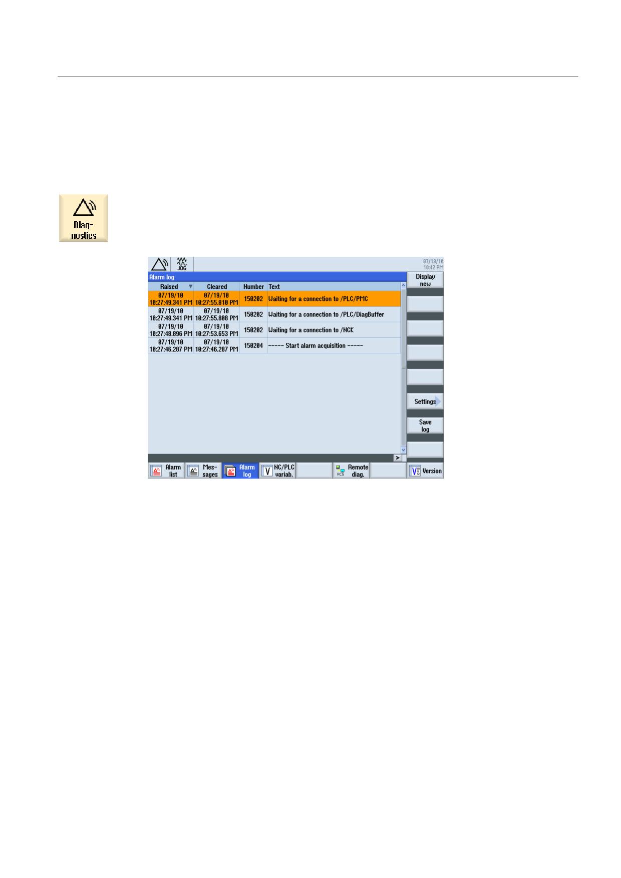
Diagnosis
Alarms and messages
Here you can see alarm lists, messages and alarm logs.
Figure 3-11 Alarm log
Turning made easy with ShopTurn
Training Documents, 09/2011, 6FC5095-0AB80-1BP1
29
Ensuring everything runs smoothly
3.2 The contents of the main menu
Turning made easy with ShopTurn
30
Training Documents, 09/2011, 6FC5095-0AB80-1BP1
Basics for beginners
4
This section explains the general basics of the geometry and technology for turning. No
inputs for ShopTurn are planned yet.
4.1
Geometrical basics
4.1.1
Tool axes and work planes
During turning, it is the workpiece, and not the tool, that rotates. The axis is the Z axis.
● G18 plane = machining with turning tools
● G17 plane = drilling and milling operations on the front face
● G19 plane = drilling and milling operations on the peripheral surface
Since the diameter of the turned workpieces is relatively easy to control, the dimensions of
the transverse axis are based on the diameter. This means that you can directly compare the
actual dimensions with the dimensions in the drawing.
4.1.2
Points in the work space
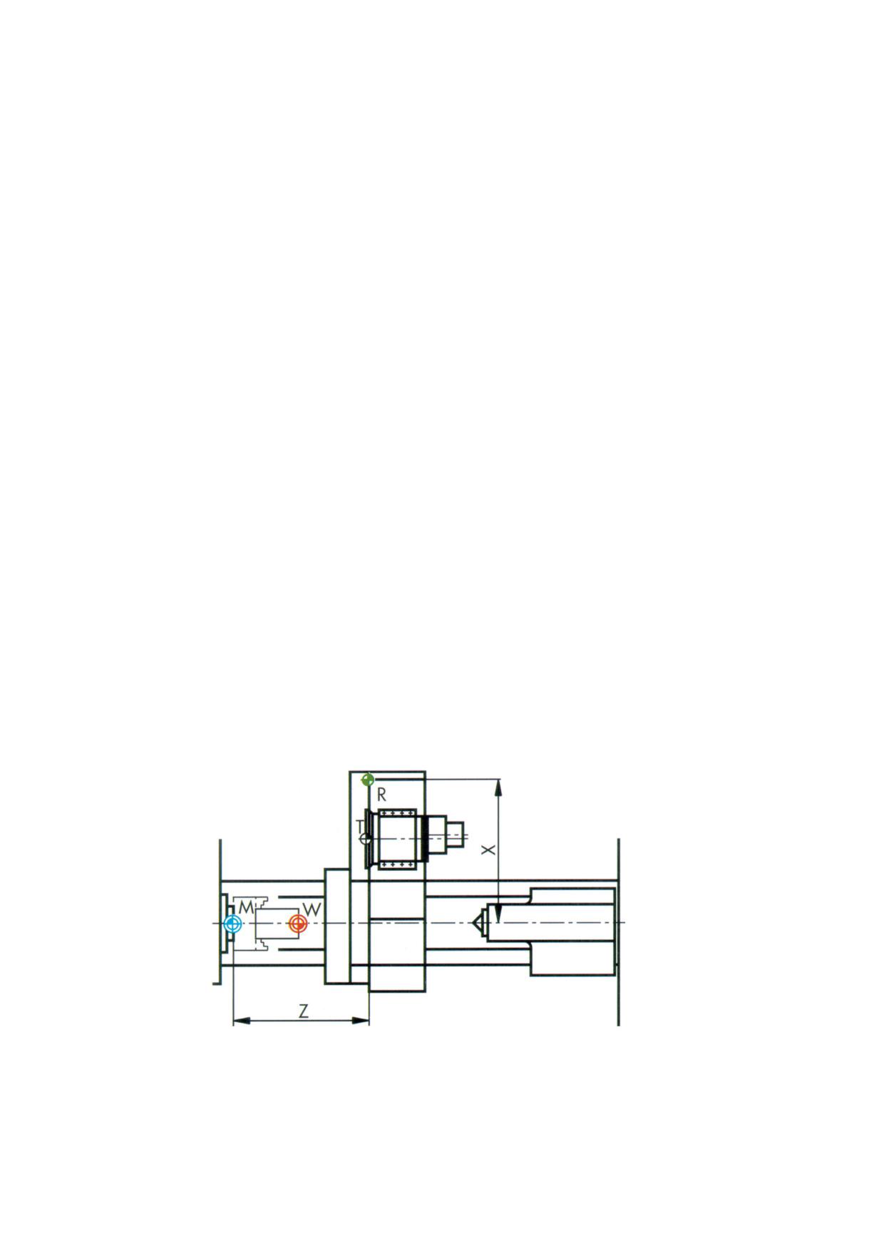
Various important reference points are provided for a CNC - such as the SINUMERIK 828D
with ShopTurn - for orientation in the working space by means of the measuring system.
Turning made easy with ShopTurn
Training Documents, 09/2011, 6FC5095-0AB80-1BP1
31
Basics for beginners
4.1 Geometrical basics
Machine zero (M)
The machine zero (M) is specified by the manufacturer and cannot be changed. It lies in the
origin of the machine coordinate system.
Workpiece zero (W)
The workpiece zero (W) - also called program zero - is the origin of the workpiece coordinate
system. It can be selected freely and should be located at a point from which the most
dimensions start in the drawing.
Reference point (R)
The reference point (R) is approached to set the measuring system to zero, as the machine
zero cannot be approached in most cases. Thus, the control system finds the start of
counting in the position measuring system.
Toolholder reference point T
Toolholder reference point T is used to set up machines with tool revolvers with default tools.
Its position and location hole permit setup with cutter holders for shank tools in accordance
with DIN 69880 and VDI 3425.
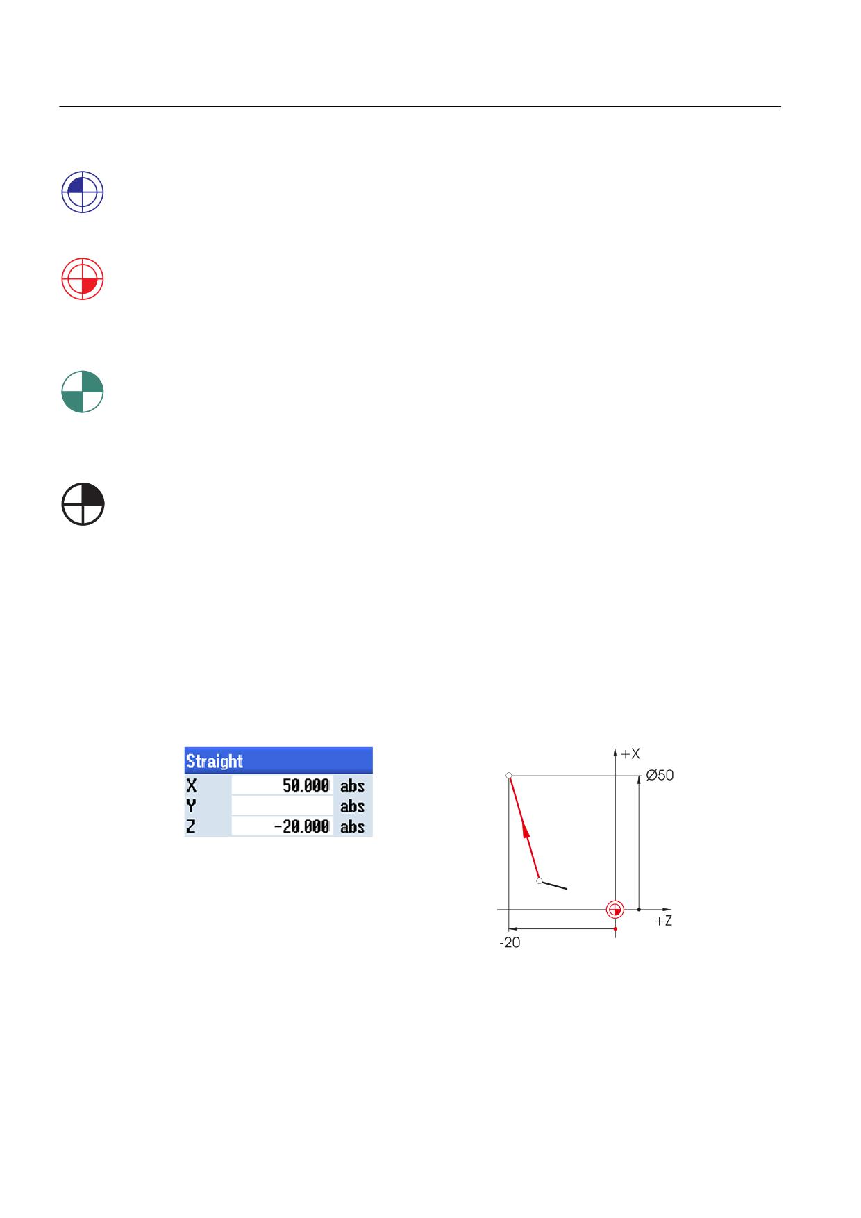
4.1.3
Absolute and incremental dimensioning
Absolute input
The entered values refer to the workpiece zero.
(QG SRLQW
&XUUHQW
* G90 Absolute dimensions
3RVLWLRQ
With absolute inputs, the absolute coordinate values of the end point must always be
entered (the current position is not taken into account).
Turning made easy with ShopTurn
32
Training Documents, 09/2011, 6FC5095-0AB80-1BP1
Basics for beginners
4.1 Geometrical basics
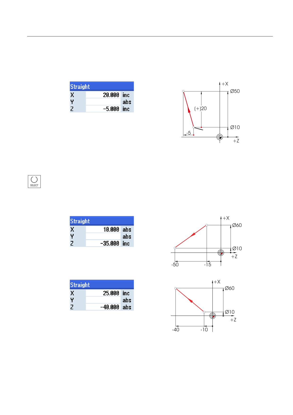
Incremental input
The entered values refer to the current position.
(QG SRLQW
* G91 Incremental dimensions
&XUUHQW
3RVLWLRQ
With incremental inputs, the difference values between the current position and the end point
must always be entered, observing the direction.
Switching between absolute and incremental input is possible at any time using the SELECT
key.
A few examples for the absolute/incremental combination can be found below:
Turning made easy with ShopTurn
Training Documents, 09/2011, 6FC5095-0AB80-1BP1
33
Basics for beginners
4.1 Geometrical basics
4.1.4
Cartesian and polar dimensions
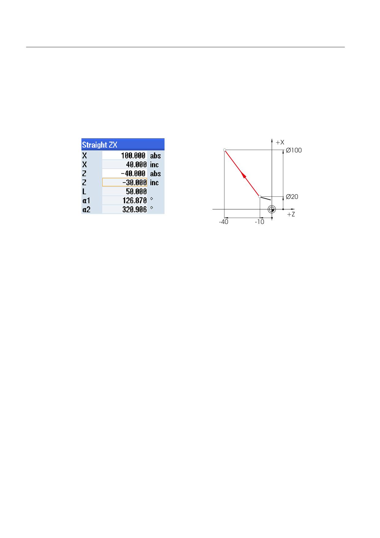
Cartesian input
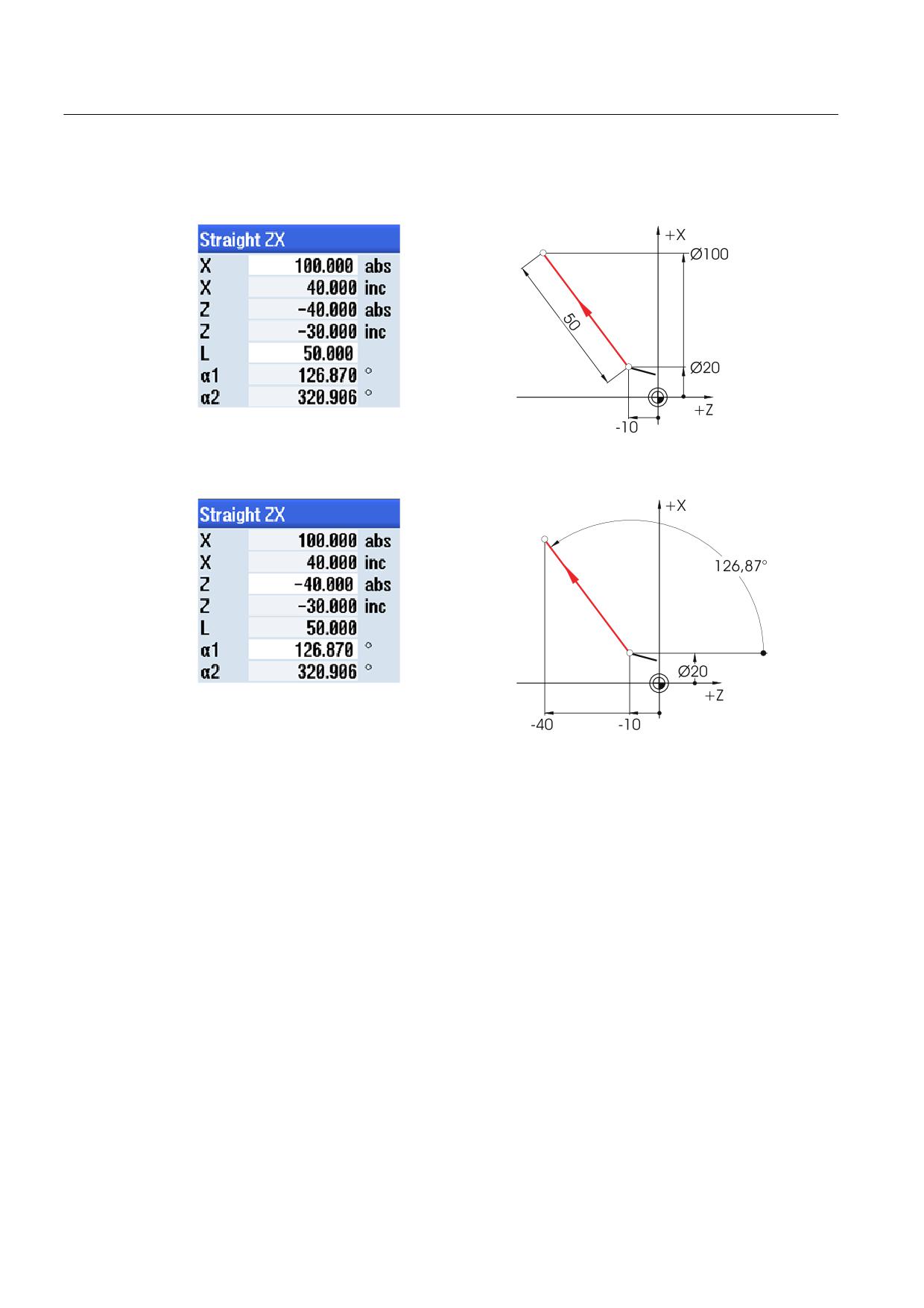
Input of the X and Z coordinates. The gray values in the example were calculated
automatically.
(QG SRLQW
With absolute inputs, the absolute coordinate values of the end point must always be
entered (the current position is not taken into account).
Turning made easy with ShopTurn
34
Training Documents, 09/2011, 6FC5095-0AB80-1BP1
Basics for beginners
4.1 Geometrical basics
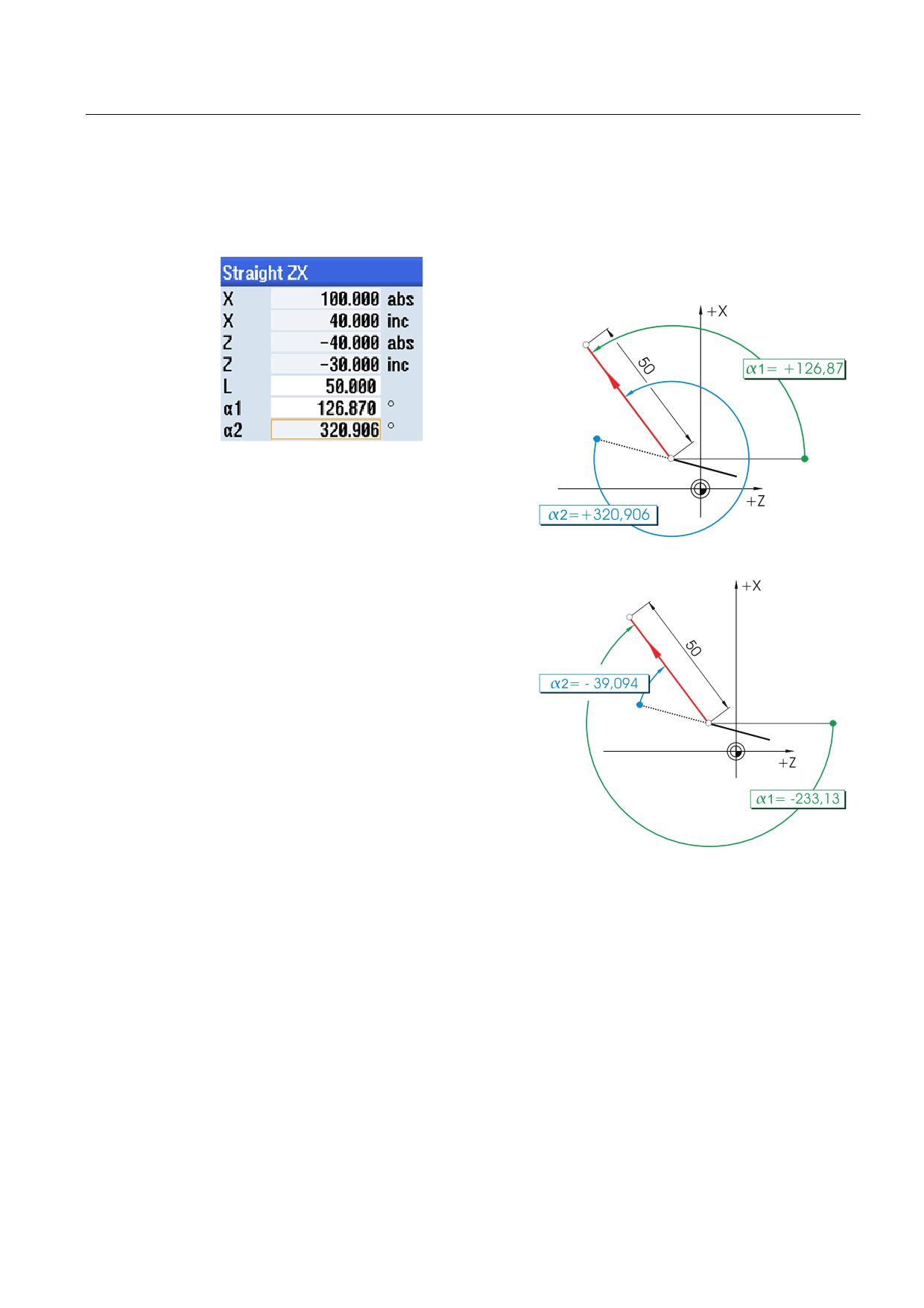
Polar input
Input of the length and angle. The gray values in the example were calculated automatically.
The angles can be entered...
positive and/or...
α1 = Angle to the positive Z axis
α2 = Angle to the preceding element
... negative.
The Cartesian and polar inputs can also be combined. Here are two examples:
Turning made easy with ShopTurn
Training Documents, 09/2011, 6FC5095-0AB80-1BP1
35
Basics for beginners
4.1 Geometrical basics
Input of the end point in X and the length
Input of the end point in Z and an angle
4.1.5
Circular motions
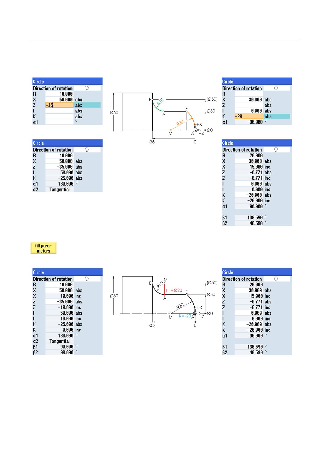
In accordance with DIN, circular arcs are specified with the end point of the arc (X and Z
coordinates in the G18 plane) and the center point (I and K in the G18 plane).
The ShopTurn contour calculator gives you the freedom to use any dimension from the
drawing for circular arcs, without having to carry out conversions.
The following example shows two circular arcs, one of which is only partially determined.
Turning made easy with ShopTurn
36
Training Documents, 09/2011, 6FC5095-0AB80-1BP1
Basics for beginners
4.1 Geometrical basics
Input of the R10 arc:
Input of the R20 arc:
After the input:
After the input:
The following displays of all values appear when you have entered all known dimensions
and pressed the All parameters softkey in the input window of the respective arc.
In DIN format:
In DIN format:
G2 X50 Z-35 CR=10
G3 X30 Z-6.771 K-20
Turning made easy with ShopTurn
Training Documents, 09/2011, 6FC5095-0AB80-1BP1
37
Basics for beginners
4.2 Technological basics
4.2
Technological basics
4.2.1
Cutting rate and speeds
The cutting rate is usually directly programmed for turning, in particular for roughing, finishing
and plunge-cutting. The speed is programmed only for drilling and (usually) for thread
cutting.
Determination of the cutting rate
First, the optimum cutting rate is determined using either the manufacturer catalogs or a
handbook.
Material of the tool:
Hard metal
Material of the workpiece:
Machining steel
Value:
vc = 180 m/min
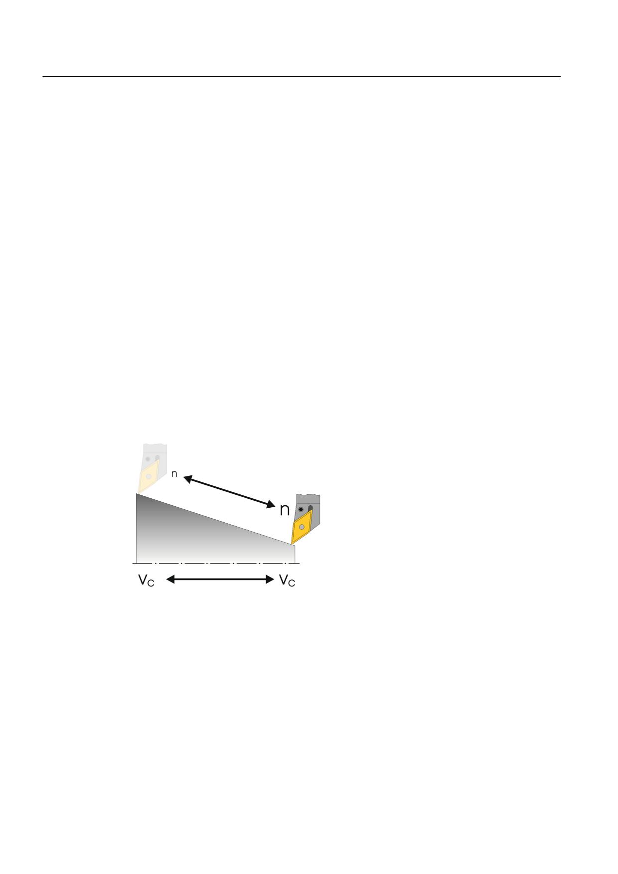
Constant cutting rate vc (G96) for rough cutting, finishing and plunge-cutting:
To ensure that the selected cutting rate
remains constant for each workpiece
diameter, the control uses the G96 command
(= constant cutting rate) to adjust the
appropriate speed. This is performed using
direct-current or frequency-controlled three-
phase motors. As the diameter reduces, the
speed will theoretically increase to infinity. To
prevent danger caused by excessive
centrifugal forces, a speed limitation
of n = 3000 rpm, for example, must be
programmed.
In DIN format, the block would have the
following form:
G96 S180 LIMS=3000
(LIMS = limit).
Turning made easy with ShopTurn
38
Training Documents, 09/2011, 6FC5095-0AB80-1BP1
Basics for beginners
4.2 Technological basics
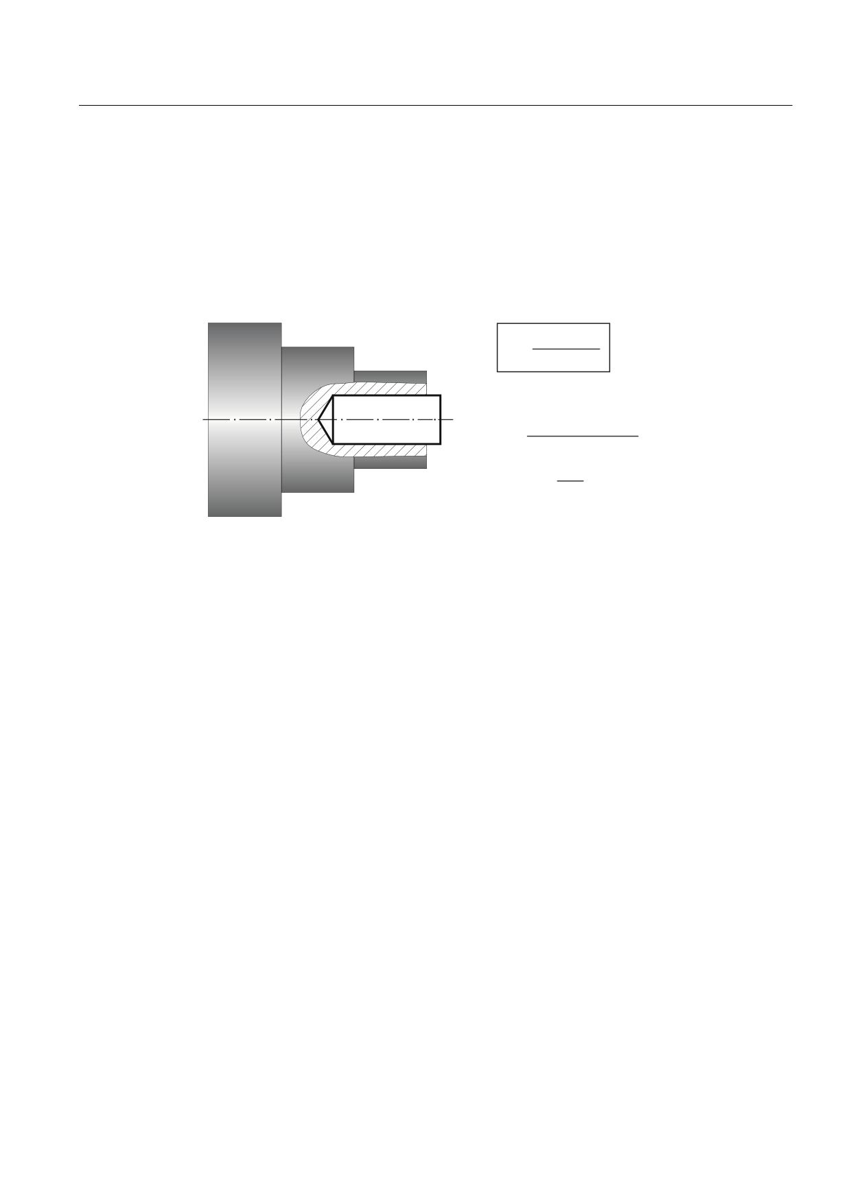
Constant speed n (G97) for drilling and thread cutting:
Since a constant speed is used for drilling, the command G97 (= constant speed) must be
used here.
The speed is dependent on the desired cutting rate (120 m/min selected here) and the tool
diameter.
The inputs are then G97 S1900.
YF y
Q
Gy˭
G
PP WRRO GLDPHWHU
PP y
Q
PP y ˭ y PLQ
Qป
PLQ
4.2.2
Feed
In the previous chapter, you learned how to determine the cutting rate and the speed. The
tool can only perform machining if the cutting rate or the speed is assigned a tool feedrate.
Determination of the feed
Like the cutting rate, the value for the feed is also taken from the handbook, the documents
of the tool manufacturer or from empirical knowledge.
Cutting material of the tool:
Hard metal
Material of the workpiece:
Machining steel
Determined value (handbook):
f = 0.2 - 0.4 mm
The mean value will be chosen:
f = 0.3 mm
Turning made easy with ShopTurn
Training Documents, 09/2011, 6FC5095-0AB80-1BP1
39
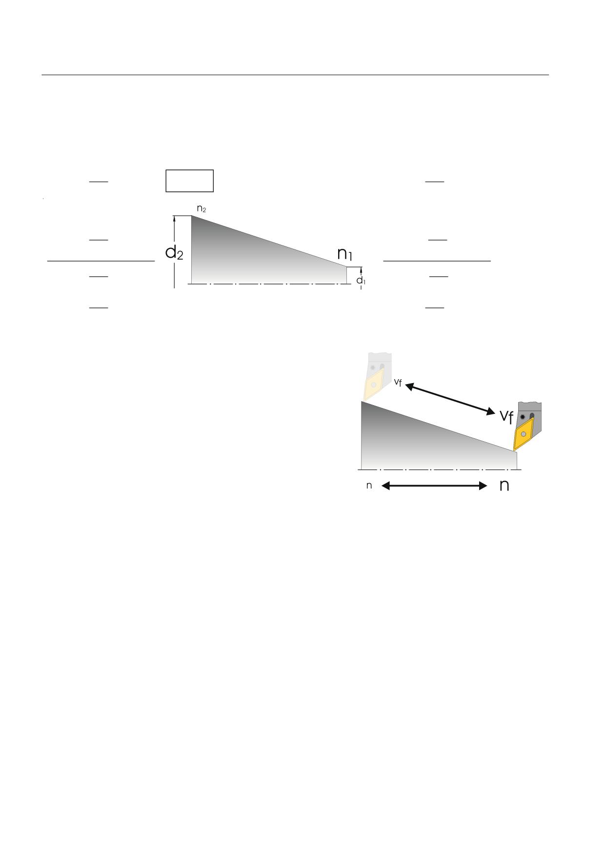
Basics for beginners
4.2 Technological basics
Relationship between feed and feedrate:
The constant feed f and the associated speed n produce the feedrate:
P
P
YI I y Q
YF
YF
PLQ
PLQ
G
PP
G
PP
Q ป
Q ป
PLQ
PLQ
YI
y
PP
YI
y
PP
PLQ
PLQ
PP
PP
YI ป
YI ป
PLQ
PLQ
Since the speed is different, the feedrate is different for the various
diameters, despite having the same feed.
Turning made easy with ShopTurn
40
Training Documents, 09/2011, 6FC5095-0AB80-1BP1
Well equipped
5
In this section you will learn how to create the tools required for the examples in the following
sections. Furthermore, it is explained how to take into account the tool lengths and how to
set the workpiece zero.
5.1
Tool management
ShopTurn offers three lists for tool management:
● the tool list
● the tool wear list
● the magazine list.
5.1.1
The tool list
The tool list displays all parameters and functions required to create and set up the tools.
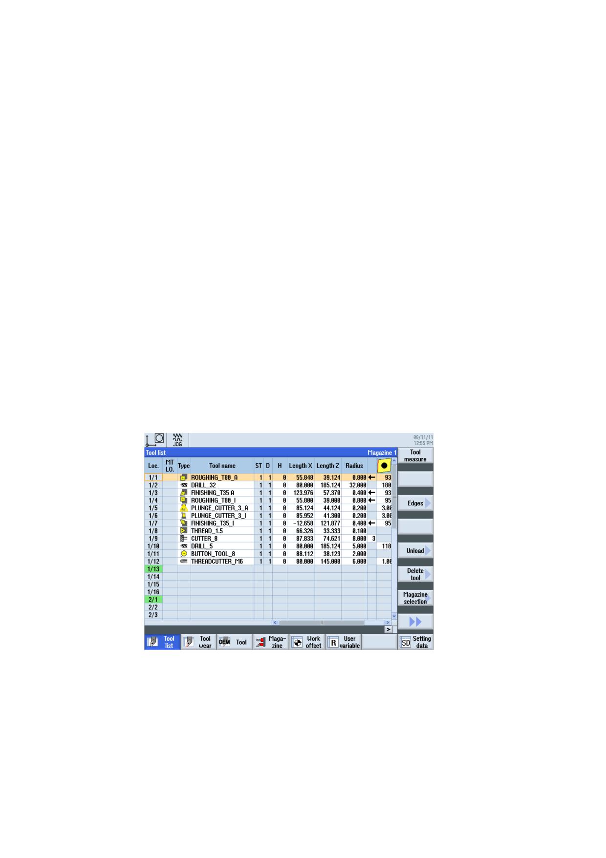
Figure 5-1
Example for tool lists
Turning made easy with ShopTurn
Training Documents, 09/2011, 6FC5095-0AB80-1BP1
41
Well equipped
5.1 Tool management
Meanings of the most important parameters:
Location
Location number
Type
Tool type
Tool name
The tool is identified by the name and the replacement tool number. You
may enter the names as text or numbers.
ST
Replacement tool number (for replacement tool strategy)
D
Cutting edge number
Length X
Geometry data, length X
Length Z
Geometry data, length Z
Diameter
Tool diameter
Holder angle, point angle,
Holder angle (roughing tool and finishing tool), point angle (drill) and
board width
board width (plunge-cutter)
Direction of spindle rotation
Coolants 1 and 2 (e.g. internal and external cooling)
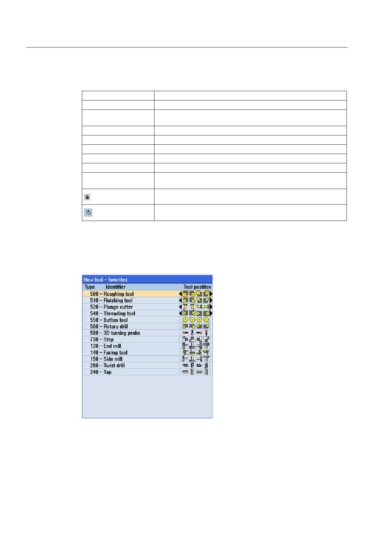
ShopTurn features various tool types (favorites, milling cutters, drills, turning tools and
special tools). Tools can be created in the tool list by means of a predefined tool catalog.
Various mounting positions and geometrical parameters exist (e.g. holder angle), depending
on the tool type.
Figure 5-2
Example of Favorites list
Turning made easy with ShopTurn
42
Training Documents, 09/2011, 6FC5095-0AB80-1BP1
Well equipped
5.1 Tool management
5.1.2
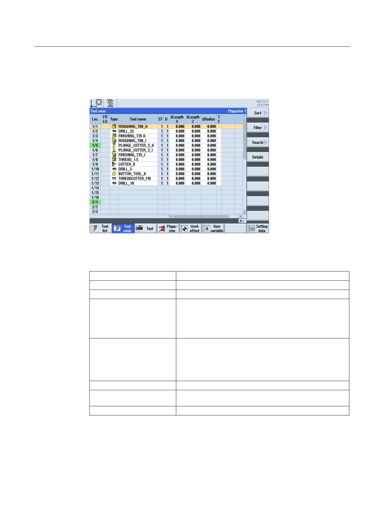
The tool wear list
The wearing data for the appropriate tools are defined here.
Figure 5-3
Tool wear list
The most important tool wearing parameters are:
Δ Length X
Length X wear
Δ Length Z
Length Z wear
Δ Radius
Radius wear
TC
Selection of tool monitoring
• by tool life (T)
• by count (C)
• by wear (W)
Tool life or
Tool life
workpiece count or
Number of workpieces
wear *
Tool wear
*Parameter depends on
selection in TC
Setpoint
Setpoint for tool life, workpiece count, or wear
Prewarning limit
Specification of the tool life, workpiece count or wear at which a
warning is displayed.
G
The tool is disabled when the checkbox is selected.
Turning made easy with ShopTurn
Training Documents, 09/2011, 6FC5095-0AB80-1BP1
43
Well equipped
5.2 Tools used
5.1.3
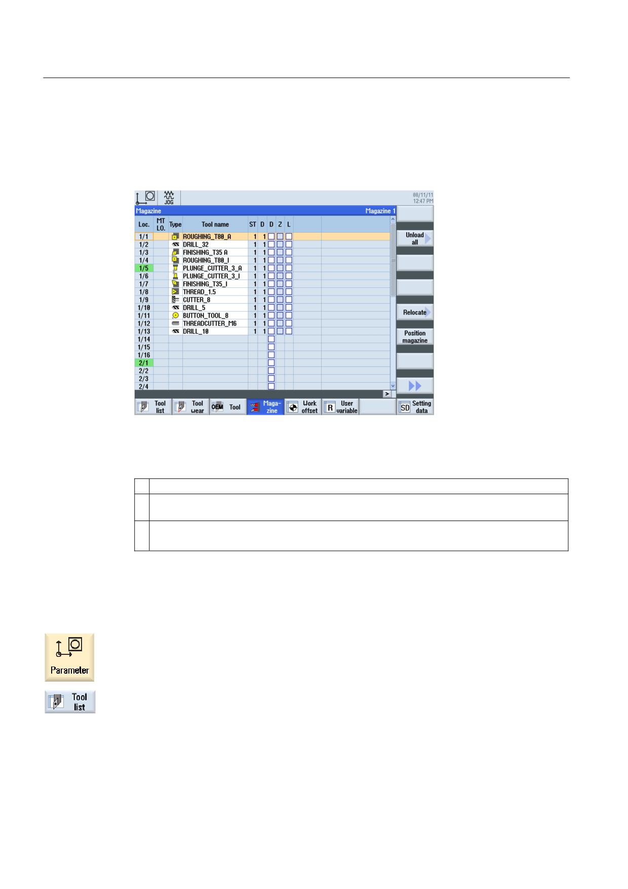
Magazine list
All tools that are assigned to one or several tool magazines are contained in the magazine
list. This list displays the condition of each tool. Individual magazine locations can be
reserved or disabled for existing tools.
Figure 5-4
Magazine list
Meanings of the most important parameters:
G
Disabling of the magazine location
Ü
Marking of a tool as oversized. The tool occupies two half locations left, two half locations right,
one half location top and one half location bottom in a magazine.
P
Fixed location coding
The tool is permanently assigned to this magazine location.
5.2
Tools used
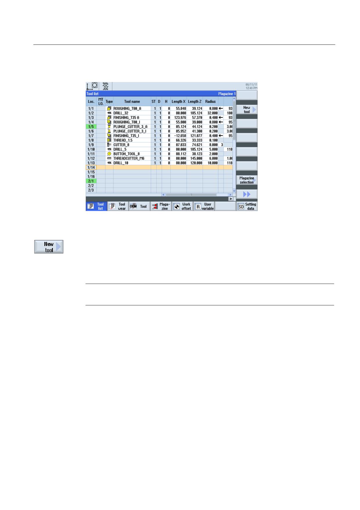
In this section you will learn how to enter tools required for the later machining in the tool list.
Select the "Parameters" area in the main menu.
Select the "Tool list” softkey.
Turning made easy with ShopTurn
44
Training Documents, 09/2011, 6FC5095-0AB80-1BP1
Well equipped
5.2 Tools used
To create a new tool, call the tool list and search for a free location.
Figure 5-5
Tool list - free location
Select the "New tool" softkey.
Select the desired tool type from the tool catalog displayed. This tool type is inserted in the
tool list and you can enter the data of the tool.
Note
Milling cutter 8 (CUTTER_8) must immerse, as it is used for milling a pocket.
Turning made easy with ShopTurn
Training Documents, 09/2011, 6FC5095-0AB80-1BP1
45
Well equipped
5.3 Tools in the magazine
5.3
Tools in the magazine
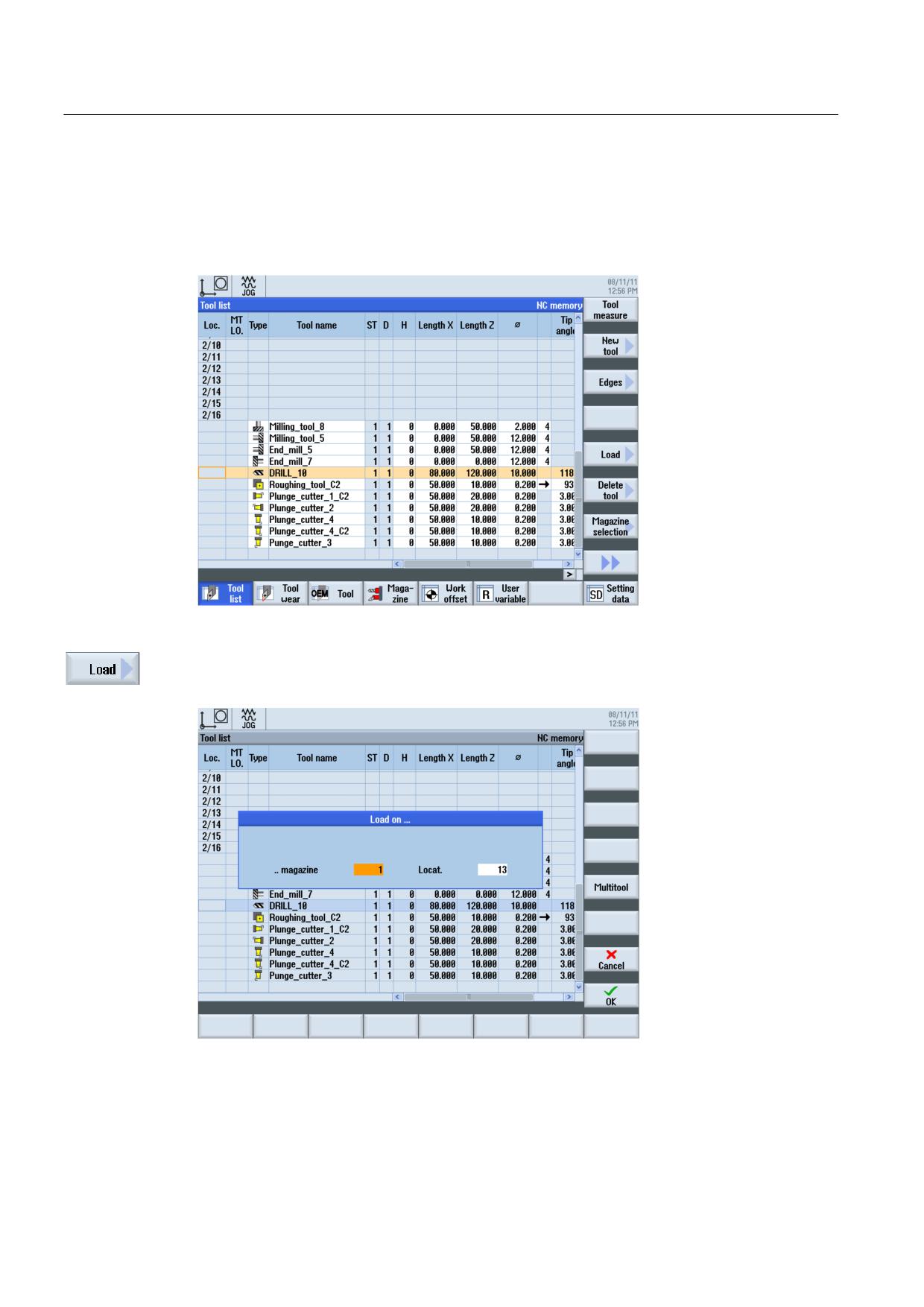
In the following you will learn how to insert the tools into the magazine.
In the tool list, select a tool without a location number.
Figure 5-6
Select the tool in the magazine
Press the "Load" key. The following dialog offers the first free magazine location for you to
change or accept directly.
Figure 5-7
Enter and/or accept a magazine location
Turning made easy with ShopTurn
46
Training Documents, 09/2011, 6FC5095-0AB80-1BP1
Well equipped
5.4 Gauging tools
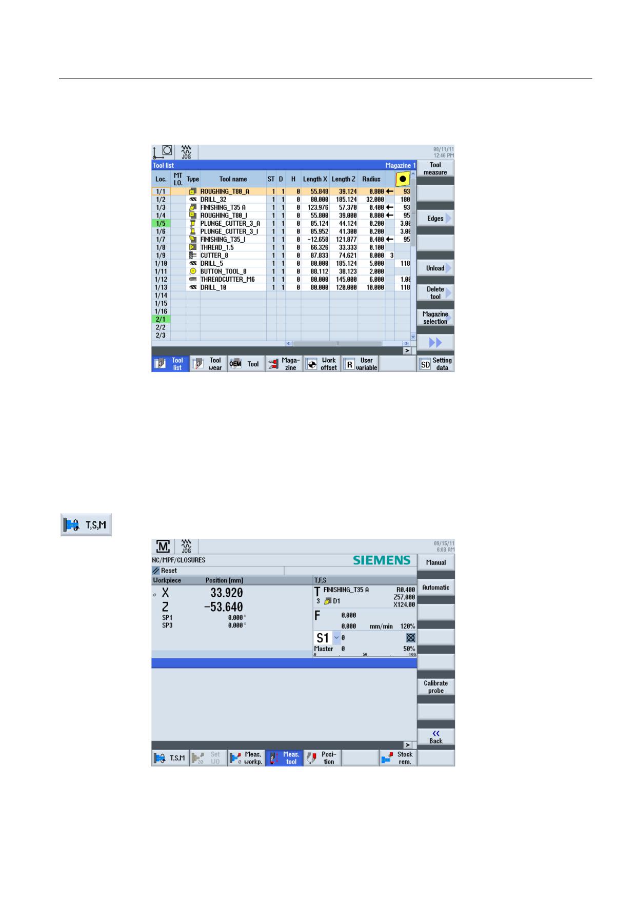
After acceptance, the tool list may look like this.
Figure 5-8
Tool list following acceptance
5.4
Gauging tools
In the following you will learn how to calculate tools.
Procedure
Insert a tool from the tool list into the spindle using the "T,S,M" softkey.
Turning made easy with ShopTurn
Training Documents, 09/2011, 6FC5095-0AB80-1BP1
47
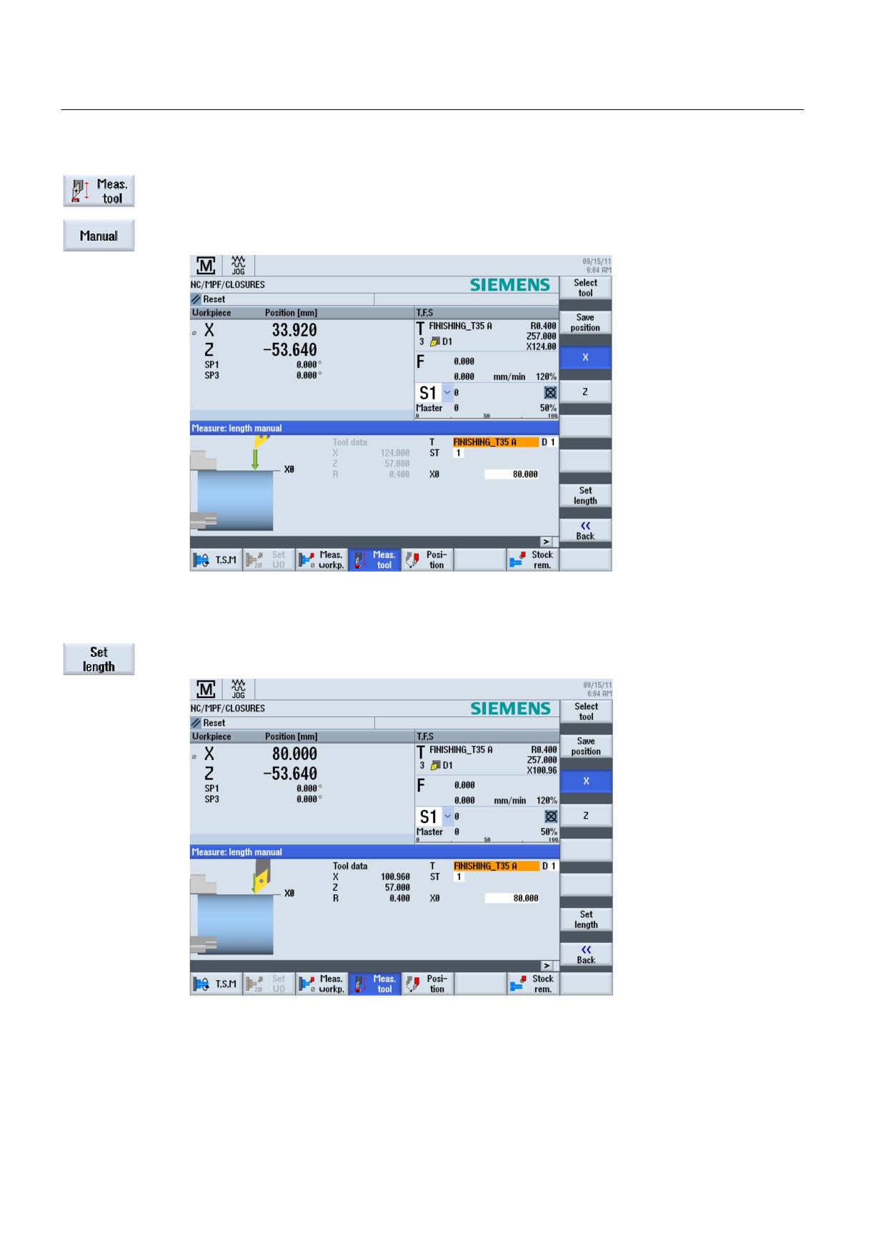
Well equipped
5.4 Gauging tools
Then switch to the "Gauge tool" menu.
Enter the probed or turned diameter.
Figure 5-9
Tool measurement - input of the X value
The current position of the tool is calculated taking into account the workpiece diameter.
Figure 5-10 Tool measurement - set length X
Turning made easy with ShopTurn
48
Training Documents, 09/2011, 6FC5095-0AB80-1BP1
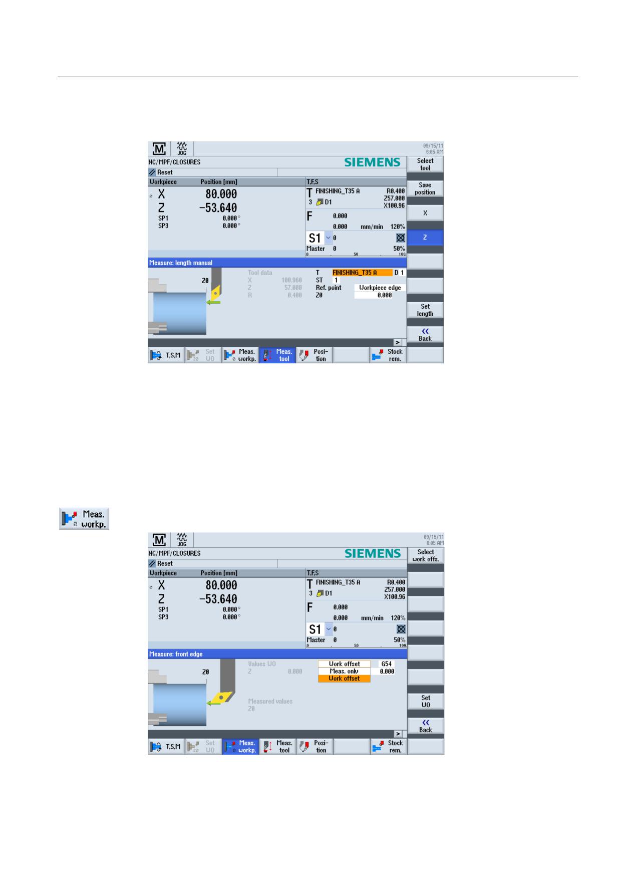
Well equipped
5.5 Setting the workpiece zero
Repeat for Z.
Figure 5-11 Tool measurement - set length Z
5.5
Setting the workpiece zero
In the following you will learn how to set the workpiece zero.
Procedure
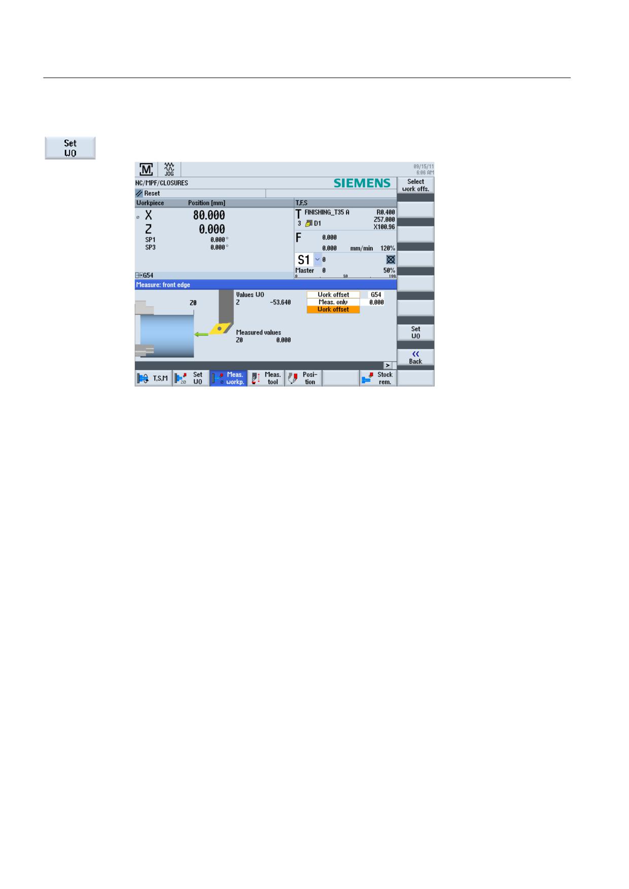
To set the workpiece zero, switch to the Machine - Manual mode in the main menu.
Move the workpiece zero if this does not lie on the end face of the workpiece.
Figure 5-12 Enter the work offset
Turning made easy with ShopTurn
Training Documents, 09/2011, 6FC5095-0AB80-1BP1
49
Well equipped
5.5 Setting the workpiece zero
Confirm your input.
Figure 5-13 Work offset set
Turning made easy with ShopTurn
50
Training Documents, 09/2011, 6FC5095-0AB80-1BP1
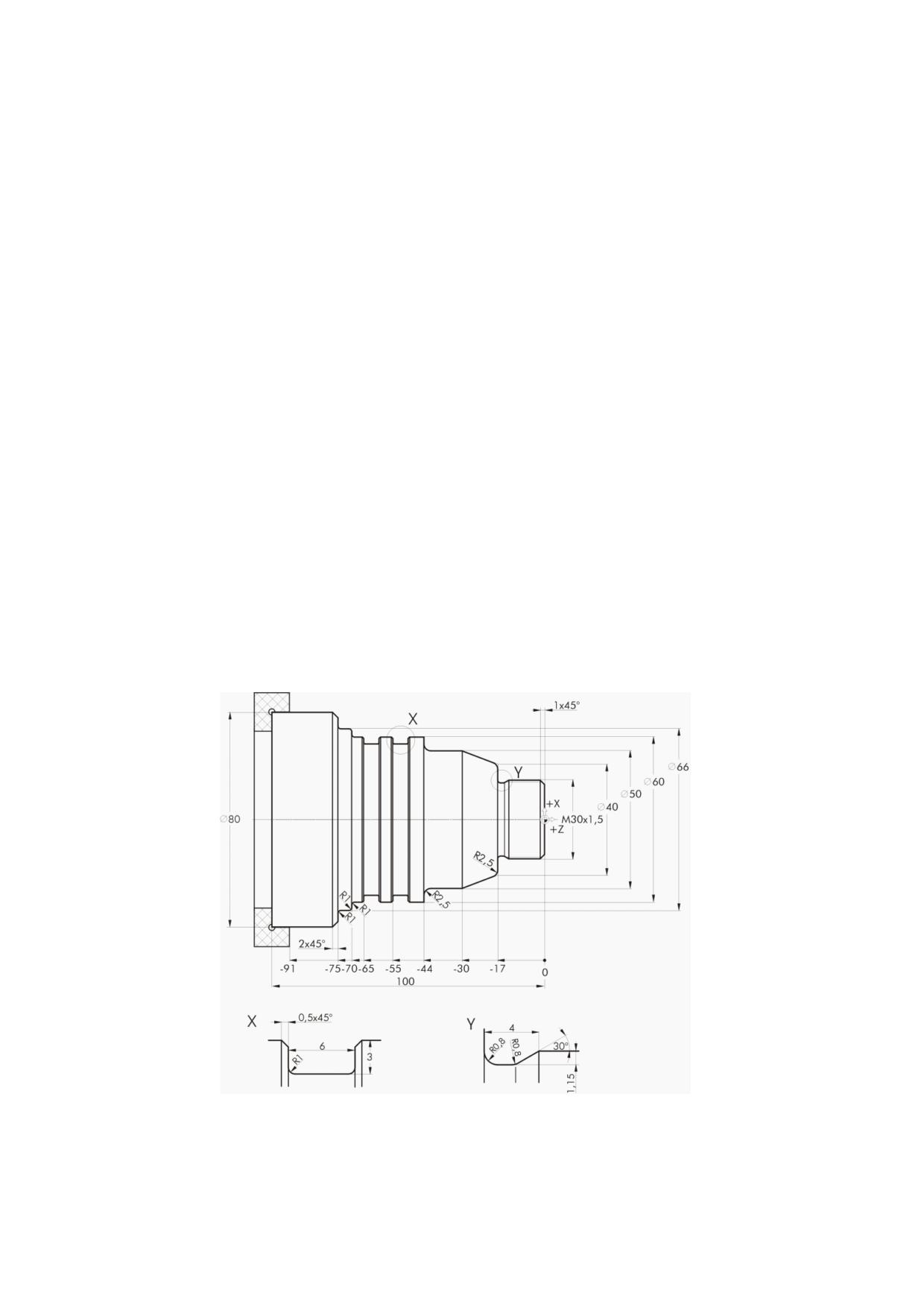
Example 1: Taper shaft
6
6.1
Overview
Learning objectives
This section will explain the first steps to create a workpiece in detail. You will learn how to...
● create and manage programs;
● call tools;
● enter traversing paths;
● create any contours with the contour calculator;
● rough and finish contours;
● create a thread undercut,
● thread and
● grooves.
Task
Figure 6-1
Workshop drawing - Example 1:
Turning made easy with ShopTurn
Training Documents, 09/2011, 6FC5095-0AB80-1BP1
51
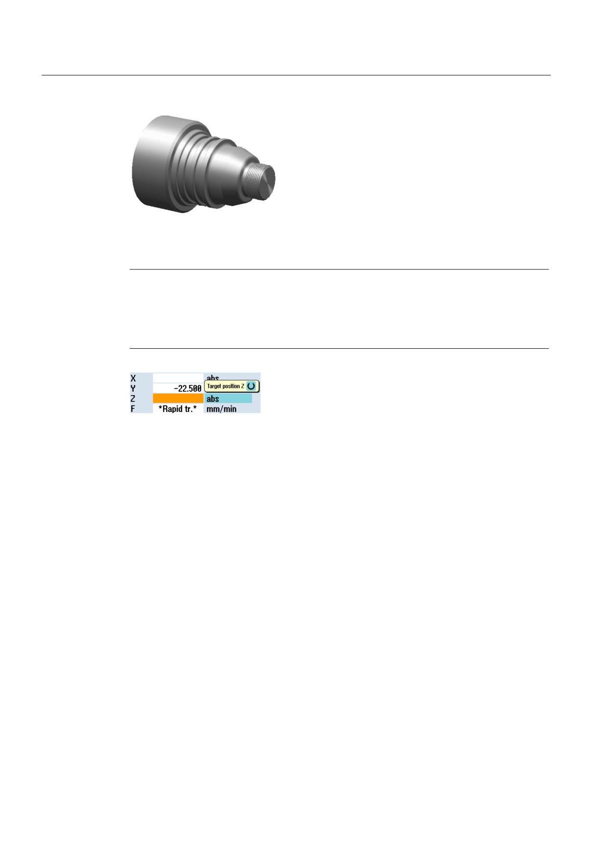
Example 1: Taper shaft
6.1 Overview
Figure 6-2
Workpiece - Example 1:
Note
ShopTurn always saves the last setting selected with the toggle key. Therefore, make sure
that all units, texts and symbols are specified as in the dialog boxes shown here in the
relevant input fields and all toggle fields.
Whenever it is possible to switch, this is indicated in the help text (see screenshot below).
Figure 6-3
Example toggle field
Turning made easy with ShopTurn
52
Training Documents, 09/2011, 6FC5095-0AB80-1BP1