SINUMERIK 840D sl. Training. Operate - Turning (2016-2020) - page 23
Straight Circle with ShopTurn
M641
13.
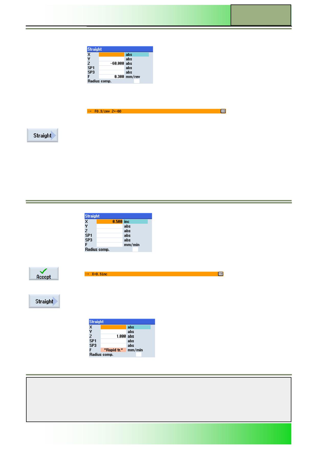
Insert the following values into the input mask:
Confirm your inputs by pressing the VSK 8 “Accept”.
The following program block is inserted into the program:
14.
Insert another “Straight”-cycle into the program.
Press the VSK 2 “Straight”, to open the input mask for the function “Straight”.
15.
Insert the following values into the input mask:
Confirm your inputs by pressing the VSK 8 “Accept”.
The following program block is inserted into the program:
15.
Insert another “Straight”-cycle into the program.
Press the VSK 2 “Straight”, to open the input mask for the function “Straight”.
16.
Insert the following values into the input mask:
Notes
828D/840Dsl SINUMERIK Operate
Page 9
M641
M641
Straight Circle with ShopTurn
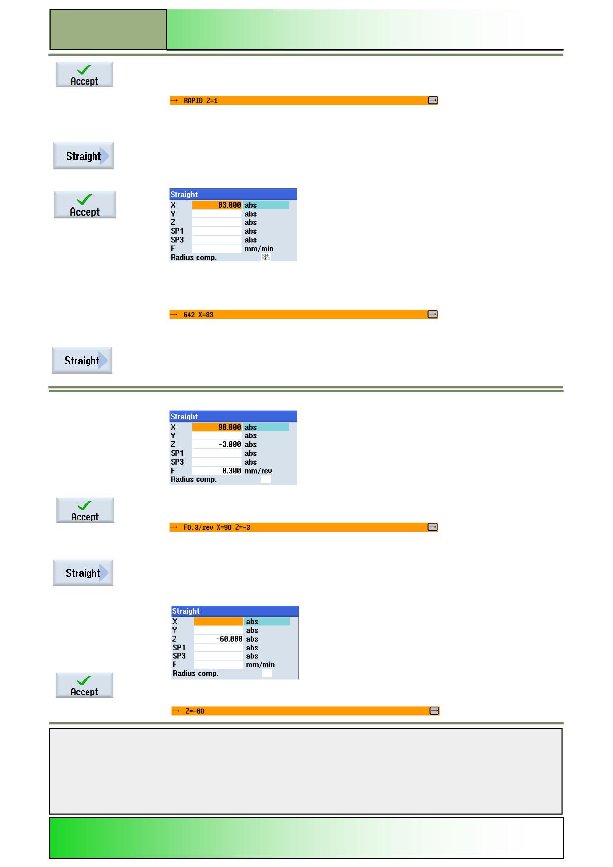
Confirm your inputs by pressing the VSK 8 “Accept”.
The following program block is inserted into the program:
17.
Insert another “Straight”-cycle into the program.
Press the VSK 2 “Straight”, to open the input mask for the function “Straight”.
18.
Insert the following values into the input mask:
Confirm your inputs by pressing the VSK 8 “Accept”.
The following program block is inserted into the program:
19.
Insert another “Straight”-cycle into the program.
Press the VSK 2 “Straight”, to open the input mask for the function “Straight”.
20.
Insert the following values into the input mask:
Confirm your inputs by pressing the VSK 8 “Accept”.
The following program block is inserted into the program:
21.
Insert another “Straight”-cycle into the program.
Press the VSK 2 “Straight”, to open the input mask for the function “Straight”.
22.
Insert the following value into the input mask:
Confirm your inputs by pressing the VSK 8 “Accept”.
The following program block is inserted into the program:
Notes
M641
Page 10
828D/840Dsl SINUMERIK Operate
Straight Circle with ShopTurn
M641
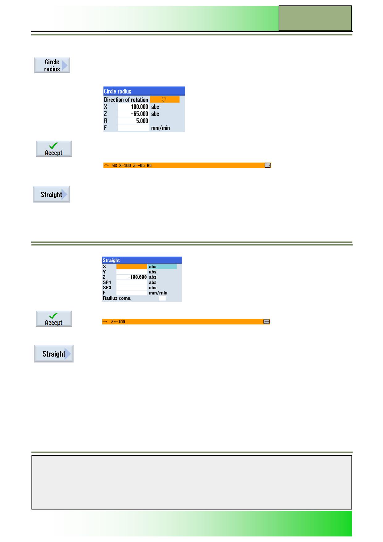
23.
Now, insert a “Circle radius”-cycle into the program.
Press the VSK 4 “Circle radius”, to open the input mask for the function “Circle radius”.
24.
Insert the following values into the input mask:
Confirm your inputs by pressing the VSK 8 “Accept”.
The following program block is inserted into the program:
25.
Insert another “Straight”-cycle into the program.
Press the VSK 2 “Straight”, to open the input mask for the function “Straight”.
26.
Insert the following value into the input mask:
Confirm your inputs by pressing the VSK 8 “Accept”.
The following program block is inserted into the program:
27.
Insert another “Straight”-cycle into the program.
Press the VSK 2 “Straight”, to open the input mask for the function “Straight”.
Notes
828D/840Dsl SINUMERIK Operate
Page 11
M641
M641
Straight Circle with ShopTurn
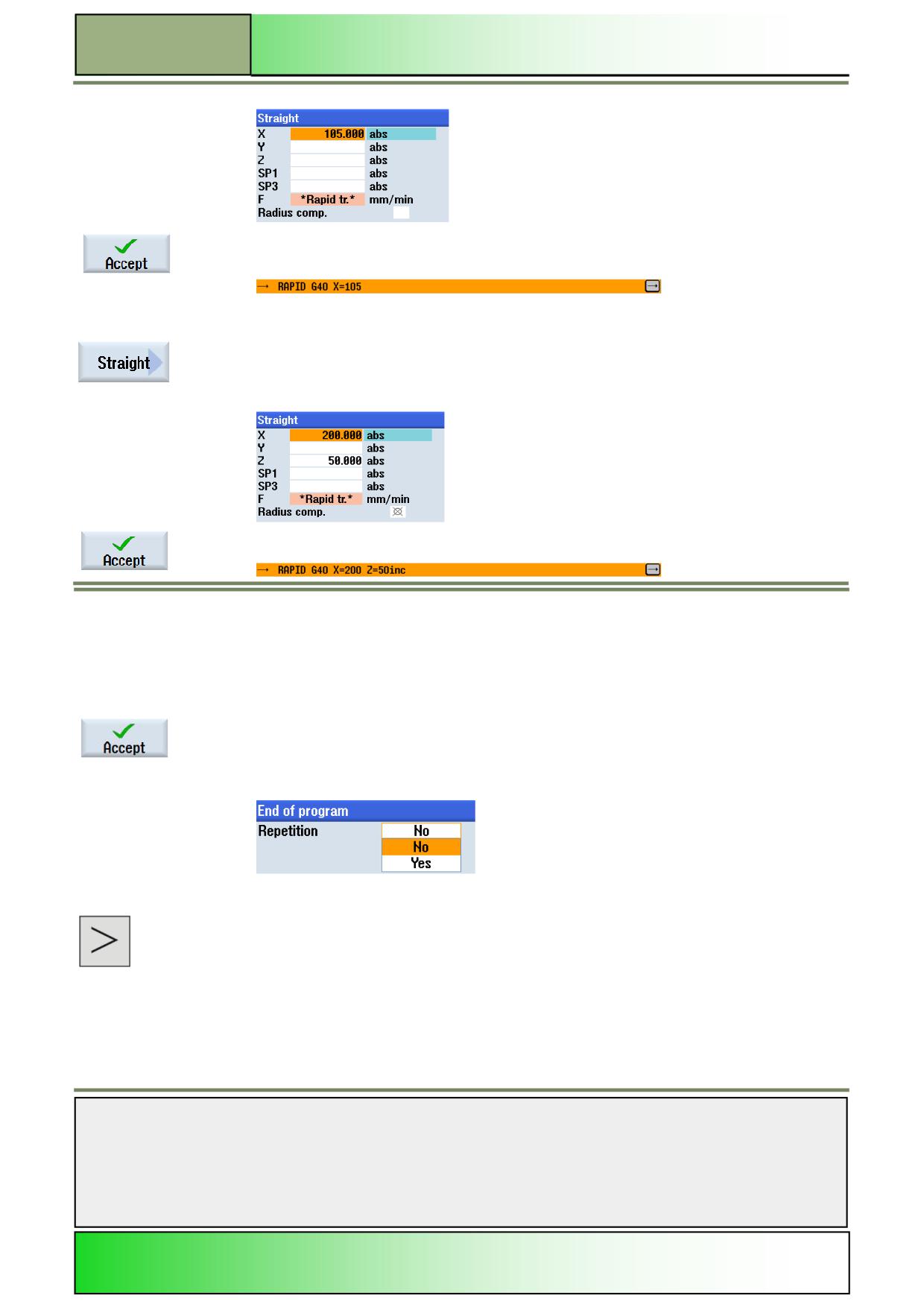
28.
Insert the following values into the input mask:
Confirm your inputs by pressing the VSK 8 “Accept”.
The following program block is inserted into the program:
29.
Now insert the last “Straight”-cycle into the program.
Press the VSK 2 “Straight”, to open the input mask for the function “Straight”.
30.
Insert the following values into the input mask:
Confirm your inputs by pressing the VSK 8 “Accept”.
The following program block is inserted into the program:
31.
Program now the end of the program and simulate the machining afterwards.
For this, place the orange selection cursor on the program block “End of program”, using the
blue cursor keys on the keyboard.
Press the “cursor-to-the-right”-key in order to switch to the input mask for the “End of pro-
gram”.
The input window for the program end opens. Here you can adjust whether you want to repeat
the program run or not.
Accept the default value “No” by pressing the VSK 8 “Accept”.
32.
To simulate the machining, switch back to the horizontal softkey bar 1.
For this press the “Menu extend”-key on the operator panel. The horizontal softkey bar 1
opens.
Notes
M641
Page 12
828D/840Dsl SINUMERIK Operate
Straight Circle with ShopTurn
M641
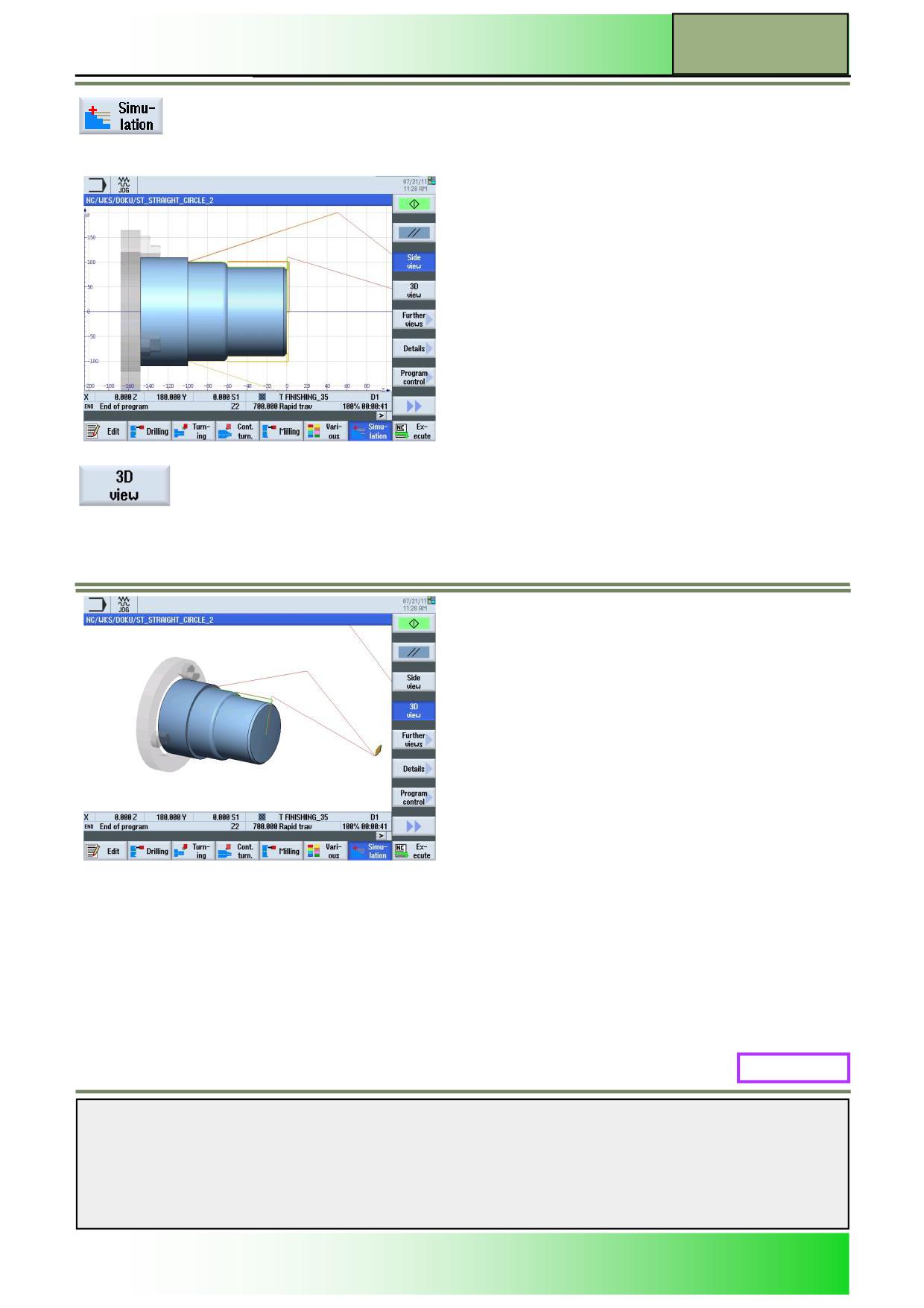
Start the simulation, by pressing the HSK 1.7 “Simulation”.
The control calculates the simulation and starts the simulation in an animation window, showing
the machining in a side view on the blank.
For a simulation with a view on the front side of the blank, press the VSK 1.4 “3D view”.
M641: END
Notes
828D/840Dsl SINUMERIK Operate
Page 13
M641

M641
Straight Circle with ShopTurn
Notes
M641
Page 14
828D/840Dsl SINUMERIK Operate
M660
Contour Milling with ShopTurn
Sinumerik
Operate
Module Description:
This module shows an example of sequential programming of contour milling in ShopTurn.
Module Objective:
This module uses a programming example to teach you about the contour milling techno-
logy with sequential programming in ShopTurn.
Content:
Simple program example
This document was produced for training purposes.
828D/840Dsl SINUMERIK Operate v4.7
Page 1
M660
Siemens assumes no responsibility for its contents.
M660
M660
Page 2
828D/840Dsl SINUMERIK Operate
Contour Milling with ShopTurn
M660
Contour Milling:
START
Simple
program
example
Contour Milling:
END
Notes
828D/840Dsl SINUMERIK Operate
Page 3
M660
M660
Contour Milling with ShopTurn
Simple programming example
Creating a new ShopTurn program
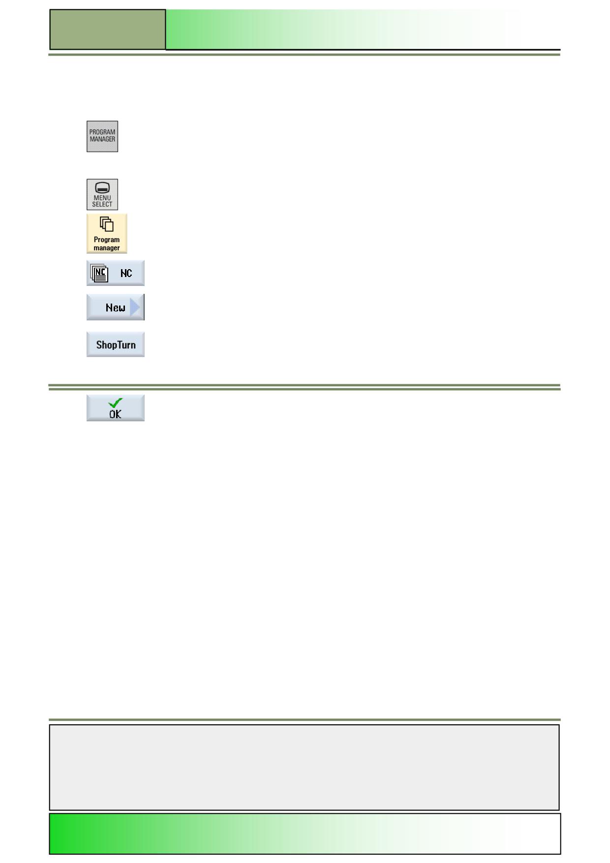
A new ShopTurn program can be created in all operating modes, as follows:
1.
Press the “Program Manager”-key on the keyboard.
The program manager opens directly.
- OR -
1.
Press the “MENU SELECT”-key on the operator panel.
Press the yellow HSK 4 “Program Manager”.
The program manager opens.
2.
Select a drive, where you want to create the program by pressing the corresponding horizontal
softkey (“NC”, “Local drive”, “USB”).
3.
Press the VSK 2 “New“.
The vertical softkey bar for creating new programs opens.
4.
Press the VSK 3 “ShopTurn” to open the input mask for creating a new ShopTurn sequential
program.
Enter a name for the program in the “Name” field and accept with pressing the VSK 8 “OK”.
The program is loaded to the editor and the input mask for the program header is opened by
default.
Description:
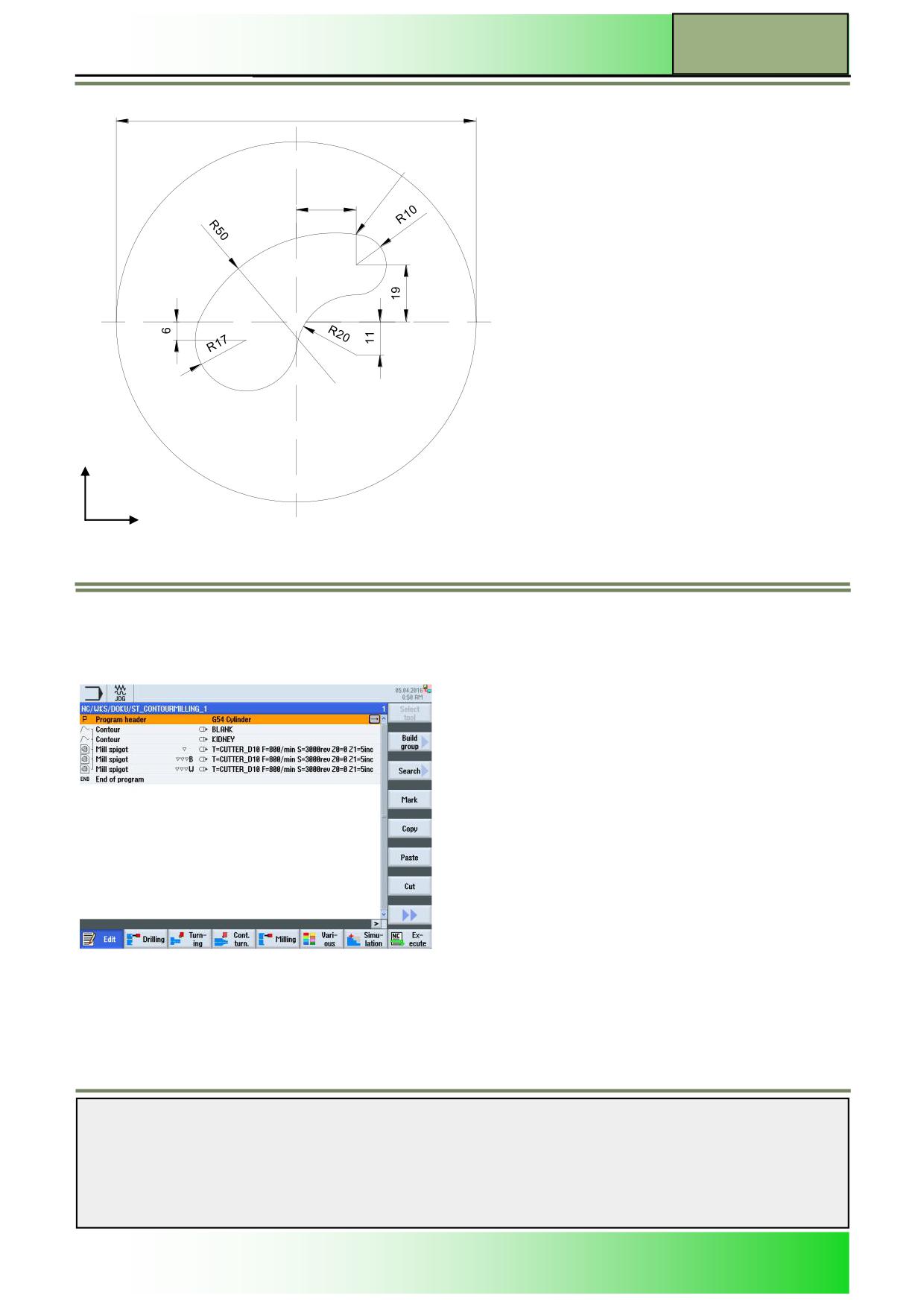
A ShopTurn program (Kidney) is to be programmed with the aid of various milling cycles (spigot).
Objective:
The workpiece shown below is to be programmed.
The program is then to be simulated.
The following tool and technology are required for the programming:
Tool and
CUTTER_D10
technology data:
(F800 mm/min, S3000 rpm)
Contour starting point:
The following position is programmed as the contour starting point:
Contour 1:
X0 Y60 (blank)
Contour 2:
X20 Y29 (kidney)
Notes
M660
Page 4
828D/840Dsl SINUMERIK Operate
Contour Milling with ShopTurn
M660
Ø120
Start
20
t=5
Y
X
Example: Kidney
The following program with call of two contour definitions as well as the spigot milling cycle is to be programmed.
1.
Create a new ShopTurn program.
Give the program a name, for example “ST_CONTOURMILLING_1.MPF”.
The input screen for the program header opens automatically.
Notes
828D/840Dsl SINUMERIK Operate
Page 5
M660
M660
Contour Milling with ShopTurn
2.
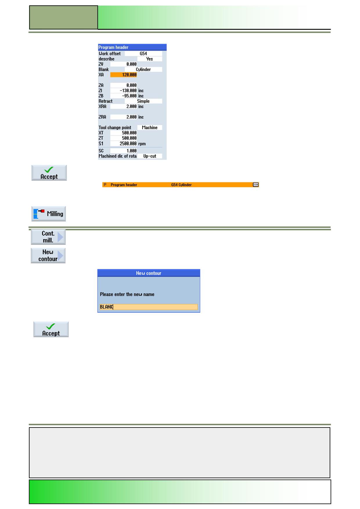
Fill in the program header as follows:
Confirm the entries with VSK 8 “Accept”.
The following “Program header” block is inserted in the machining plan:
3.
Program the first contour definition.
To do this, press HSK 1.5 “Milling” to call the “Milling” technology.
Then press VSK 8 “Contour milling” to call the “Contour milling” technology.
Press VSK 1 “New contour”.
An input window for the assignment of a contour name opens.
4.
Confirm the entry with VSK 8 “Accept”.
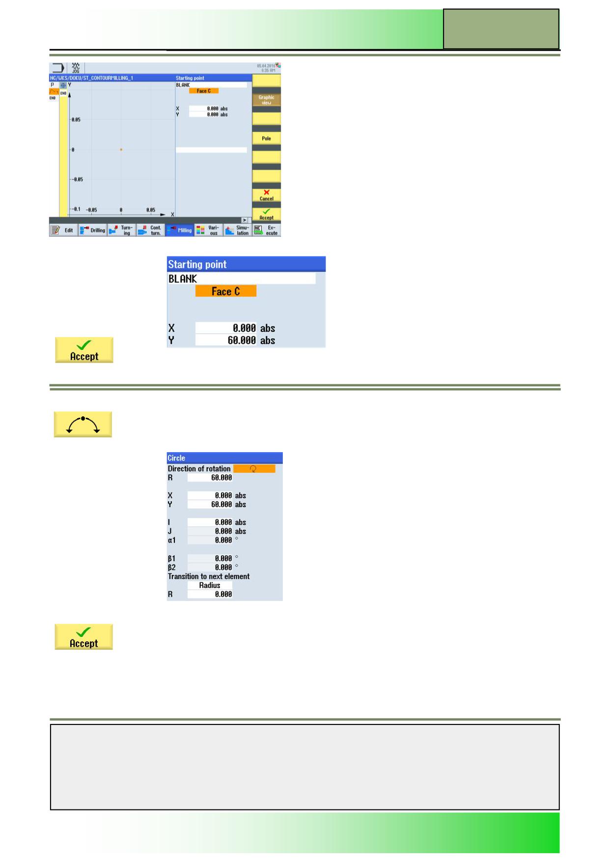
The operating area for the contour input opens with the input window for the contour starting
point (which can be recognized by the yellow bar with the contour increments and the pro-
gramming symbols on the left-hand edge of the screen as well as the yellow vertical softkey
bar on the right-hand side):
Notes
M660
Page 6
828D/840Dsl SINUMERIK Operate
Contour Milling with ShopTurn
M660
5.
Enter the following coordinates as starting point:
Confirm the entries with VSK 8 “Accept”.
6.
Extend the contour with a circular movement in the clockwise direction.
Press VSK 1.5 “Circle”.
The input window for the contour element of a
circular movement opens.
7.
ows:
Confirm the entries with VSK 8 “Accept”.
Note:
When entering the circle center point in X (“I”), a dialog selection is opened. Note the input
screen and the changing color of the graphic if you press the “Select dialog” softkey several
times.
If your entries in the input screen are correct, press the “Accept dialog” softkey to accept
these entries.
8.
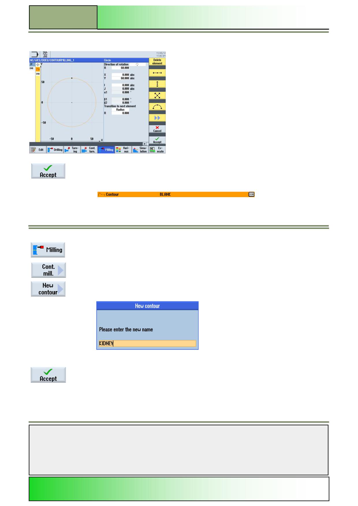
Now check your entries for the first contour. (See figure on the next page.)
Notes
828D/840Dsl SINUMERIK Operate
Page 7
M660
M660
Contour Milling with ShopTurn
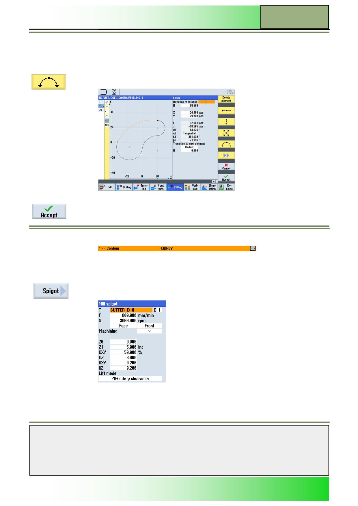
The following screen with the finished contour definition is displayed:
Finish the contour definition by pressing VSK 8 “Accept”.
The following “Contour” program block is inserted in the machining plan:
The step sequence is opened (which can be recognized by the open bracket on the right next
to the programming symbol).
Now insert another contour in the program.
9.
To do this, press HSK 1.5 “Milling” to call the “Milling” technology.
Then press VSK 8 “Contour milling” to call the “Contour milling” technology.
Press VSK 1 “New contour”.
An input window for the assignment of a contour name opens.
10.
Confirm the entries with VSK 8 “Accept”.
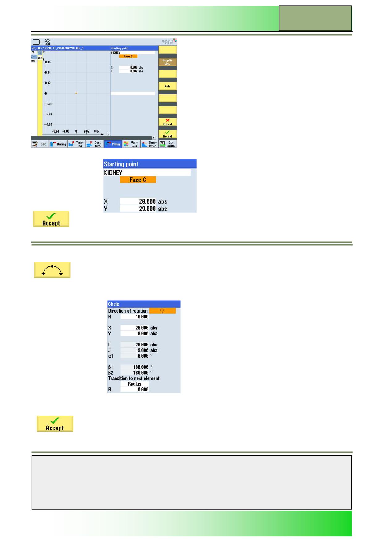
The operating area for the contour input opens with the input window for the contour starting point (which can be recog-
nized by the yellow bar with the contour increments and the programming symbols on the left-hand edge of the screen as
well as the yellow vertical softkey bar on the right-hand side).
Notes
M660
Page 8
828D/840Dsl SINUMERIK Operate
Contour Milling with ShopTurn
M660
11.
Enter the following coordinates as starting point:
Confirm the entries with VSK 8 “Accept”.
12.
Extend the contour with a circular movement in the clockwise direction.
Press VSK 1.5 “Circle”.
The input window for the contour element of a circular movement opens.
13.
Enter the coordinates as follows:
Confirm the entries with VSK 8 “Accept”.
Note:
(When entering the circle center point in X (“I”), a dialog selection is opened. Note the input
screen and the changing color of the graphic if you press the “Select dialog” softkey several
times.
If your entries in the input screen are correct, press the “Accept dialog” softkey to accept these
entries.)
Notes
828D/840Dsl SINUMERIK Operate
Page 9
M660
M660
Contour Milling with ShopTurn
14.
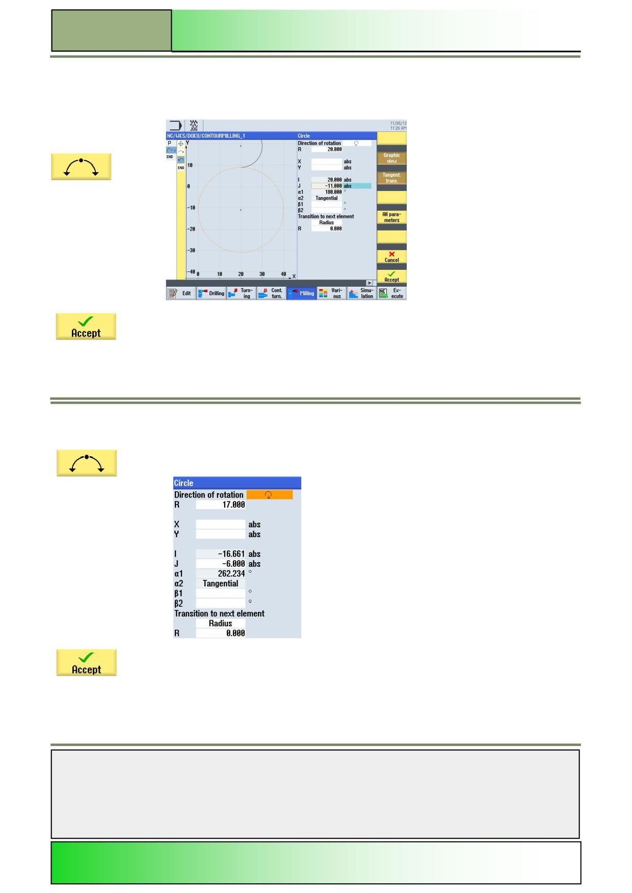
Extend the contour with a circular movement in the clockwise direction.
Press VSK 1.5 “Circle”.
The input window for the contour element of a
circular movement opens.
Confirm the entries with VSK 8 “Accept”.
Note:
(When entering the parameters, activate the “Tangent prev. elem.” softkey to receive the tan-
gential transition to the previous element.)
15.
Extend the contour with a circular movement in the clockwise direction.
Press VSK 1.5 “Circle”.
The input window for the contour element of a circular movement opens.
Confirm the entries with VSK 8 “Accept”.
Note:
(When entering the parameters, activate the “Tangent prev. elem.” softkey to receive the tan-
gential transition to the previous element.)
Notes
M660
Page 10
828D/840Dsl SINUMERIK Operate
Contour Milling with ShopTurn
M660
Note:
(When entering the parameters, activate the “Tangent prev. elem.” softkey to receive the tan-
gential transition to the previous element.)
Extend the contour with a circular movement in the clockwise direction.
16.
Press VSK 1.5 “Circle”.
The input window for the contour element of a
circular movement opens.
1
Finish the contour definition by pressing VSK 8 “Accept”.
The following “Contour” program block is inserted in the machining plan:
The step sequence is extended and opened downward (which can be recognized by the open
bracket on the right next to the programming symbol).
18.
Add a spigot milling cycle to the program.
Now press VSK 1.6 “Spigot” to call the input screen for the milling cycle.
19.
Notes
828D/840Dsl SINUMERIK Operate
Page 11
M660
M660
Contour Milling with ShopTurn
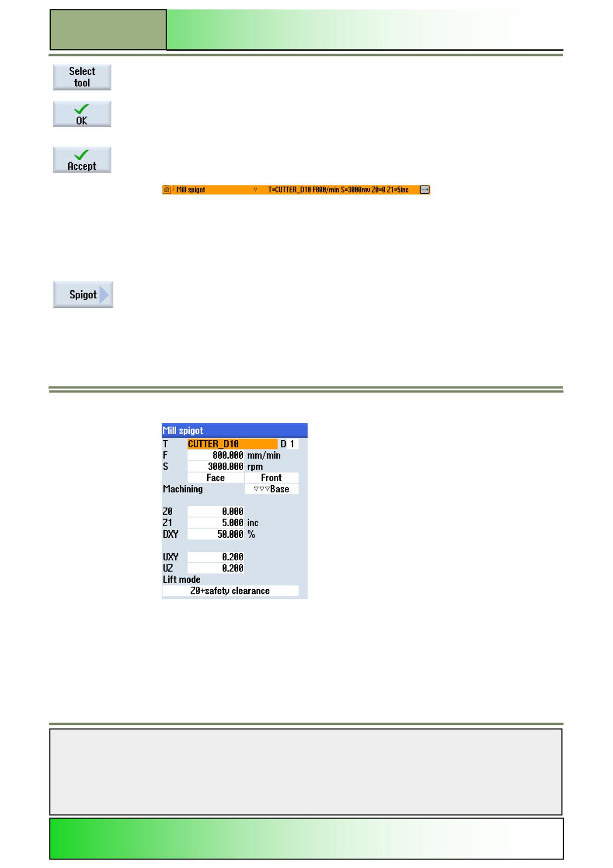
To insert a tool press VSK 1 “Select tool”.
Select the appropriate tool in the tool list (here
CUTTER_D10) with the orange selection cursor and press VSK 8 “OK”.
Confirm the entries with VSK 8 “Accept”.
The “Mill spigot” program block is inserted in the machining plan:
The step sequence is extended.
20.
Add a cycle for further spigot milling.
Press VSK 1.6 “Spigot” to call the input screen for the milling cycle.
21.
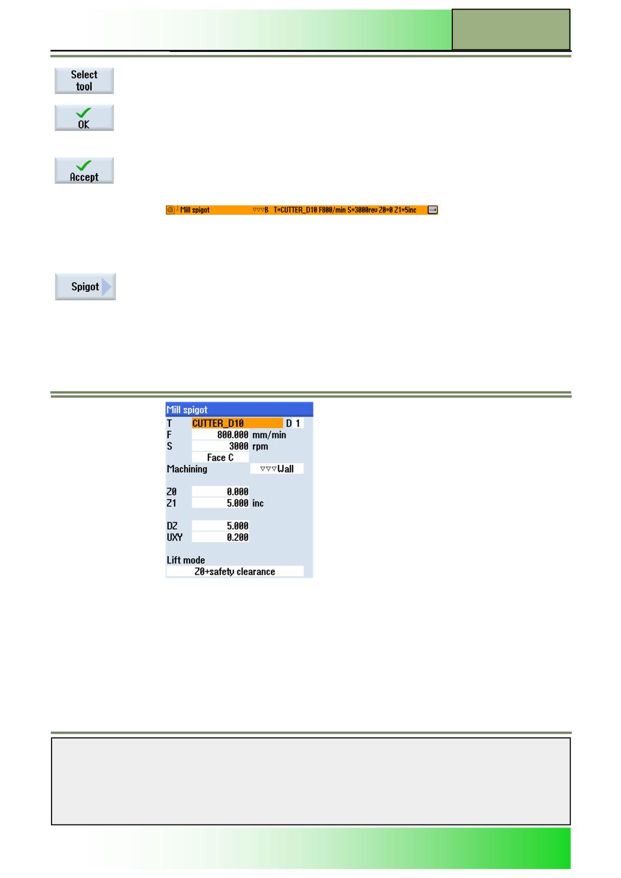
Fill in the input screen as follows:
22.
Notes
M660
Page 12
828D/840Dsl SINUMERIK Operate
Contour Milling with ShopTurn
M660
To insert a tool press VSK 1 “Select tool”.
Select the appropriate tool in the tool list (here
CUTTER_D10) with the orange selection cursor and press VSK 8 “OK”.
Confirm the entries with VSK 8 “Accept”.
The “Mill spigot” program block is inserted in the machining plan:
The step sequence is extended.
23.
Add a last spigot milling cycle to the program.
Press VSK 1.6 “Spigot” to call the input screen for the milling cycle.
Notes
828D/840Dsl SINUMERIK Operate
Page 13
M660
M660
Contour Milling with ShopTurn
24.
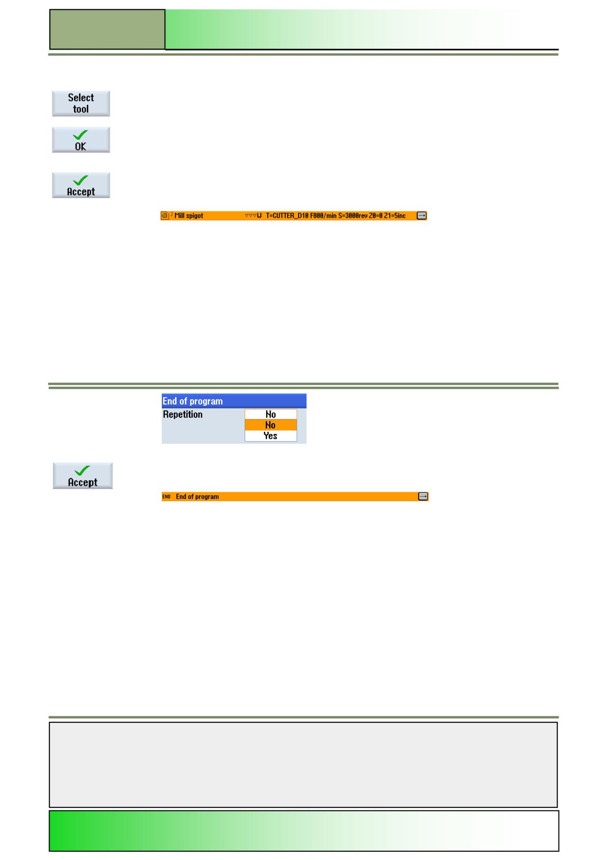
To insert a tool press VSK 1 “Select tool”.
Select the appropriate tool in the tool list (here
CUTTER_D10) with the orange selection cursor and press VSK 8 “OK”.
Confirm the entries with VSK 8 “Accept”.
The last “Mill spigot” program block is inserted in the machining plan:
The step sequence is now closed.
25.
Program the end of the program and simulate the machining.
Place the orange selection cursor on the “End of program” program block and extend the line
by pressing the blue “Cursor right” key on the keyboard.
26.
The input screen for the end of the program opens. Here you can select whether the program is
to be repeated for several workpieces.
Leave the settings at the default value “No” and confirm this with VSK 8 “Accept”.
The “End of program” program block is updated:
Notes
M660
Page 14
828D/840Dsl SINUMERIK Operate
Contour Milling with ShopTurn
M660
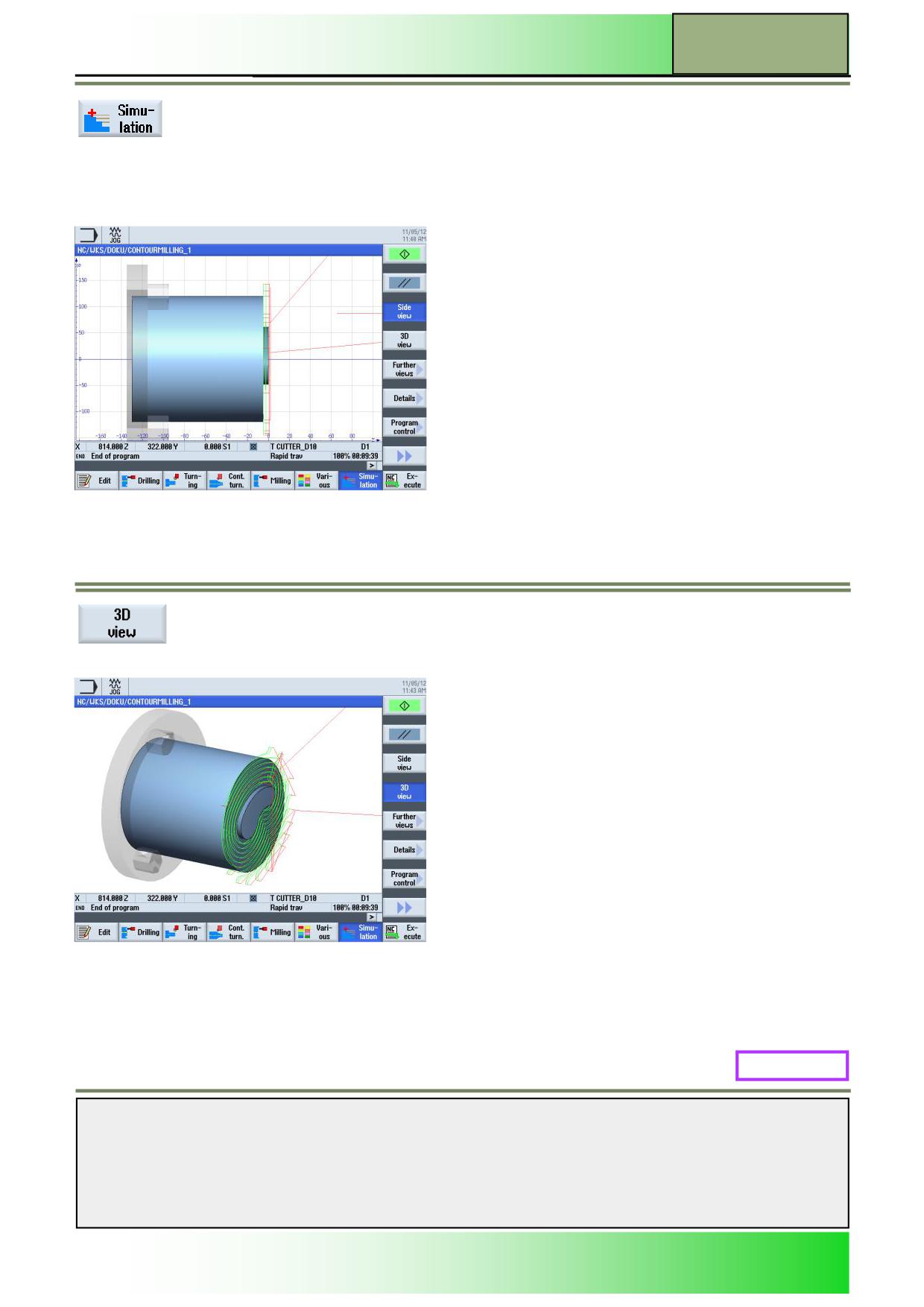
Press HSK 1.7 “Simulation” to start the simulation of the program.
The control calculates the simulation and opens the Simulation window as standard with the
“Side view” of the blank.
To view the simulation on the face end of the blank, press VSK 1.4 “3D view”.
M660: END
Notes
828D/840Dsl SINUMERIK Operate
Page 15
M660

M660
Contour Milling with ShopTurn
Notes
M660
Page 16
828D/840Dsl SINUMERIK Operate
M605
Basics of programming with the program-
Sinumerik
GUIDE
Operate
Module Description:
This module explains the general program structure of a ShopTurn G code program, programmed
with the programGUIDE. Furthermore the functions of the “Editor“ are described, as well as the func-
tions “Various “.
Module Objective:
Working with this module you will learn the concept of the G code programming with the
ShopTurn programGUIDE.
Content:
Basics
Creating G-code programs
Editor
Various
This document was produced for training purposes.
828D/840Dsl SINUMERIK Operate v4.7
Page 1
M605
Siemens assumes no responsibility for its contents.
M605
M605
Page 2
828D/840Dsl SINUMERIK Operate
Basics of programming with the programGUIDE
M605
Basics with
programGUIDE:
START
Basics
Creating
G-code
programs
Editor
Various
Basics with
programGUIDE:
END
Notes
828D/840Dsl SINUMERIK Operate
Page 3
M605
M605
Basics of programming with the programGUIDE
Basics
G code programming with ShopTurn
ShopTurn offers beside the manual operation, are the possibility to create NC programs on the control. These programs can
be of the type chained sequential programs, G code programs or a mix of both.
If you do not want to program with the ShopTurn functionality, you can
generate G code programs with G code commands in the ShopTurn user interface. G code commands can be programmed
as per DIN 66025.
Note:
The creation of chained sequential programs is explained in detail in the module - M601 - „Basics of programming with
ShopTurn”.
With the G code programming in ShopTurn with the programGUIDE, parameter masks guide you in the process of measur-
ing, programming of contours, as well as drilling, turning and milling cycles.
From within the parameter masks, G code will be generated, which can also be translated back into the parameter masks.
The following functions simplify the programming of G code programs:
Technology oriented program step selection (cycles) using softkeys
Input masks and -windows for parameters, with animated help graphics
Context sensitive online help for every input mask and window
Comfortable definition of the blank
Support for the contour input (geometric processor)
ShopTurn programs can be represented in different views:
As a work plan showing the call up of the tool, path commands, revolution settings, spindle data, feed, cycle calls, the
program end, etc.
Notes
M605
Page 4
828D/840Dsl SINUMERIK Operate
Basics of programming with the programGUIDE
M605
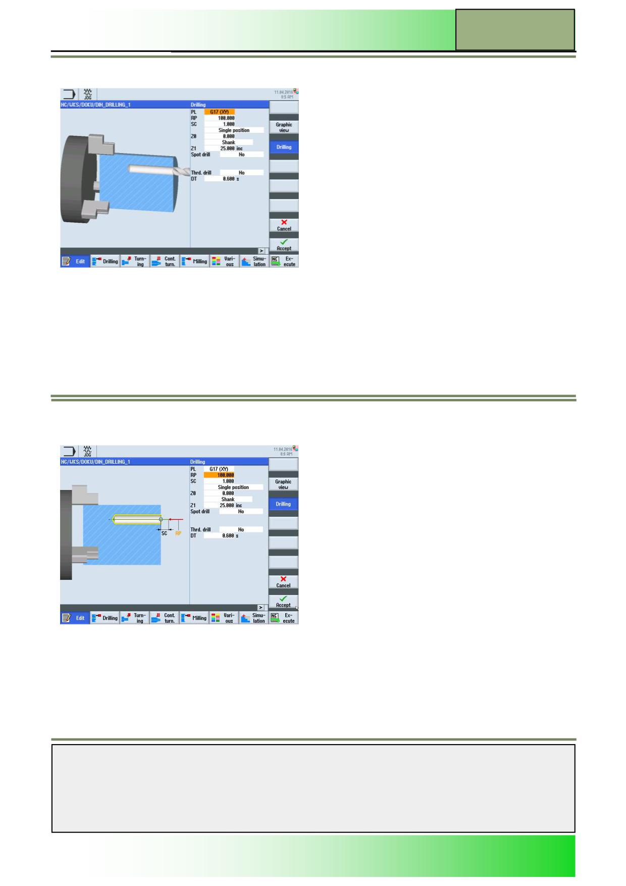
As a parameter mask, with 3D animations during parameter input of cycles and blank definition.
As a parameter mask, with help graphics during parameter input of cycles and blank definition. .
Notes
828D/840Dsl SINUMERIK Operate
Page 5
M605
M605
Basics of programming with the programGUIDE
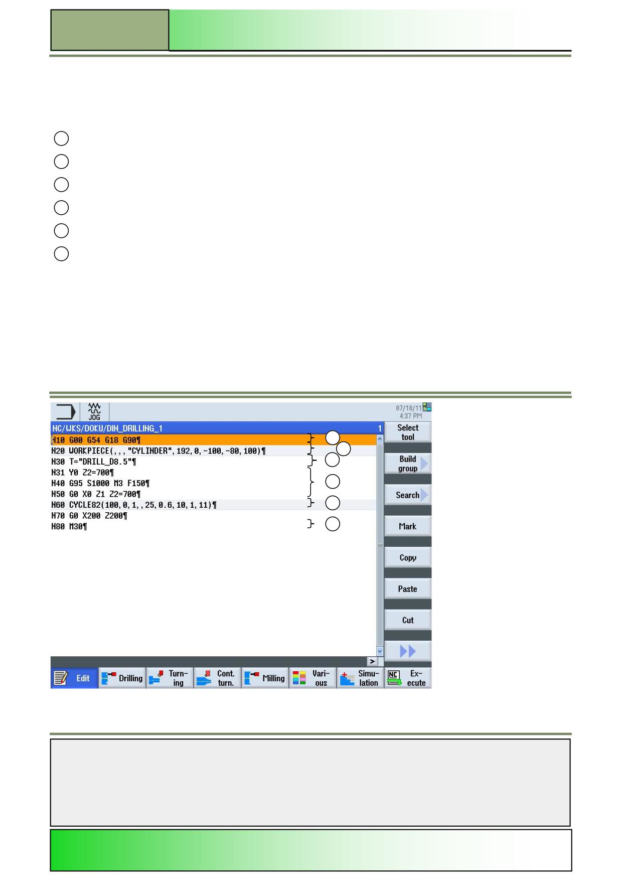
General program structure
In general a G code program can be programmed freely.
For a good legibility however, the following structure is recommended:
1
Zero point selection, plane selection, absolute dimensioning
2
Blank attribution for the simulation
3
Tool call-up and tool change
4
Technology data, path commands
5
Programming of the technologies (cycles)
6
Program end
1
2
3
4
5
6
Notes
M605
Page 6
828D/840Dsl SINUMERIK Operate

Basics of programming with the programGUIDE
M605
Standard commands in the G code Editor
Unlike in a program with ShopTurn functionality the following G-code commands are programmed through graphically sup-
ported parameter masks, where as in the programGUIDE G-code editor they have to be specifically typed into the editor.
Note:
Unnamed G commands are freely selectable.
The documentation of the machine manufacturer must be observed.
Command
Meaning
G 00
Rapid traverse command
G 01
Linear interpolation (Feed motion)
G 02
Circular interpolation anti-clockwise
G 03
Circular interpolation clockwise
G 04
Dwell time
Note: Additional parameter inputs are required
G 17
Plane selection XY Z
G 18
Plane selection ZX Y
G 19
Plane selection YZ X
G 54 - G 57
Selection of the zero points
Note:
More zero points may be available.
The documentation by the machine manufacturer must be observed.
G 90
Absolute dimensions
G 91
Incremental dimensions
The following standard M commands are available in the G code editor.
Note: Unnamed M-commands are freely selectable. The documentation by the machine manufacturer must be observed.
Command
Meaning
M00
Programmed Halt
M01
Optional stop, see also M00
M02
End of Program
M03
Spindle Start clockwise
M04
Spindle Start anti-clockwise
M05
Spindle Stop
M06
Tool change
M08
Coolant ON
M09
Coolant OFF
M19
Defined spindle stop
M30
End of Program (see also M02)
Notes
828D/840Dsl SINUMERIK Operate
Page 7
M605
M605
Basics of programming with the programGUIDE
The following standard “other“ commands are available in the G code editor.
Note:
The documentation by the machine manufacturer must be observed.
Command
Meaning
T
Tool call-up (Tool)
S
Speed (Speed)
F
Feed rate (Feed)
Navigation in the editor window
For a fast and comfortable navigation within a G code program and the parameter masks you can use the blue cursor
keys.
With the blue “cursor-up”-key on the keyboard you can navigate upwards in the program editor
and the parameter masks.
With the blue “cursor-down”-key on the keyboard you can navigate downwards in the program
editor and the parameter masks.
The arrow symbol (extend symbol) on the right side of a cycle or workpiece line in the editor
window indicates that you can enter the parameter input mask by pressing the “cursor-to-the-
right”-key
The “cursor-to-the-right”-key opens the parameter mask of the corresponding program block.
The “cursor-to-the-left”-key closes the parameter mask for the cycle or workpiece settings and
brings you back to the editor window, displaying the G code program.
Creating G Code programs
Creating a new G code program or opening an existing one
A new G code program can be created from the operating modes “JOG”, “MDA” and “AUTO” as follows:
Press the “Program Manager“-key on the keyboard.
The program manager for creating and administering programs opens directly.
See module M525 - „Operating area Program Manager“.
- OR -
Press the “MENU SELECT“ key on the operator panel (OP).
Press the yellow HSK 1.4 “Program Manager“.
The program manager for creating and administering programs opens.
Notes
M605
Page 8
828D/840Dsl SINUMERIK Operate
Basics of programming with the programGUIDE
M605
- THEN -
Select a storage drive by pressing the horizontal softkey “NC”, “Local drive” or “USB”, where
you want to create the program.
Move the orange cursor with the blue cursor-keys to the directory of your choice.
For the navigation process refer to the modules M516 - “Operating elements“ or module M525
- “Operating area Program Manager“.
Press the VSK 2 “New”.
The vertical softkey bar with functions for creating new programs opens.
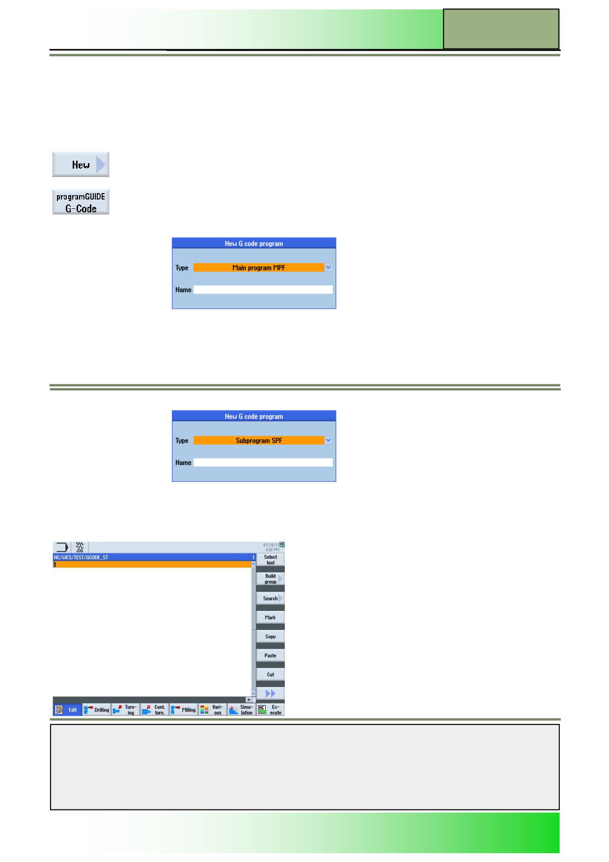
Press the VSK 4 „programGUIDE G code“, to open the input mask for creating a new G code
program.
Here you can create a new main program,
or a new subprogram.
Enter a name for the program and confirm your input by pressing the VSK 8 “OK”, or abort
with pressing the VSK 7 “Cancel”.
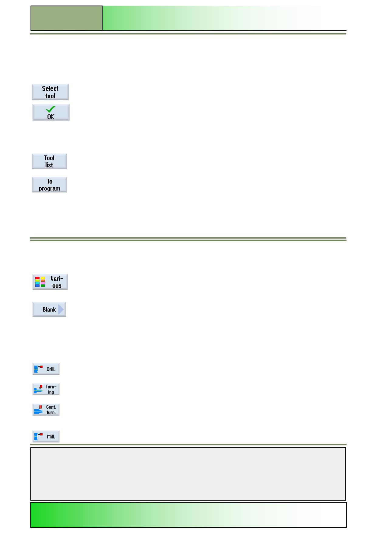
After creating a new programGUIDE program, the program will be loaded into the G code editor in the operating area
“Program”, where all the functions for entering and editing G code commands and cycles are available (see picture below).
Notes
828D/840Dsl SINUMERIK Operate
Page 9
M605
M605
Basics of programming with the programGUIDE
Programming a tool
Within the editor, tools can be selected and inserted in the G code program comfortably by using a
softkey.
Under the function “Edit” HSK 1 press the VSK 1.1 “Select Tool” to open the tool selection win-
dow.
You can use the cursor key to select the tool you require followed by pressing the VSK 1.8 “OK”
- OR -
Press the VSK 1.1 “Tool list” Will open the tool list in the operating area “Parameter”.
(see module - M523 “Operating area Parameter”).
Select an already existing tool from the tool list by placing the orange selection cursor on that
tool and pressing the VSK 1.1 “To program”.
Afterwards program the tool change (M06), the spindle start (M03/M04), the coolant (M07/M08),
the speed (S...), the feed (F) and if needed, some tool specific functions.
Programming the blank
The blank is needed for the simulation and the simultaneous recording. A realistic simulation is only possible with a blank,
that represents the actual blank dimensions as close as possible.
The shape (Block centred, Pipe, Cylinder or N-corners) and dimensions of the blank must be defined.
In the operating area “Program” press the HSK 1.6 “Various” to open the vertical softkey bar with
“various” functions.
Here, press the VSK 1.1 “Blank” to open the input mask for defining the blank.
Fill in the needed parameters and press the VSK 8 “Accept” to take over the blank settings into the pro-
gram or abort with pressing the VSK 7 “Cancel”.
Programming a cycle
Cycles (technologies) can be programmed easily by using softkeys and parameter masks.
In the operating area “Program”
press the HSK 1.2 “Drill.”, or
press the HSK 1.3 “Turning”, or
press the HSK 1.4 “Cont. turn.”, or
press the HSK 1.5 “Mill.”
to open the cycles for drilling, turning, contour turning and milling.
Select the corresponding technology (cycle) and optionally a position pattern and accept for inserting the
Notes
cycle into the G code program.
See modules M611 - “Drilling“, M626 - “Contour turning” and M661 - “Contour Milling“.
M605
Page 10
828D/840Dsl SINUMERIK Operate
Basics of programming with the programGUIDE
M605
Select the corresponding technology (cycle) and optionally a position pattern and accept for inserting the
cycle into the G code program.
See modules M611 - “Drilling“, M626 - “Contour turning” and M661 - “Contour Milling“.
Inserting G code commands and programming the program end
In the G code editor window several functions for inserting, copying and cutting G code commands are available.
In the operating area “Program” press the HSK 1 “Edit” to program a part program with G code com-
mands or to edit an already loaded program.
Program the program end (M02/M30).
Press the HSK 1.7 “Simulation“ to simulate the machining.
- OR -
Press the HSK 1.8 “NC Execute” to load the program to the NC memory, ready for machining.
Edit
Explanation of the function “Edit”
With the editor you can create, supplement, or change part programs.
Selecting the function “Edit”
The program editor can be opened from the operating modes “JOG”, “MDA” or “AUTO”..
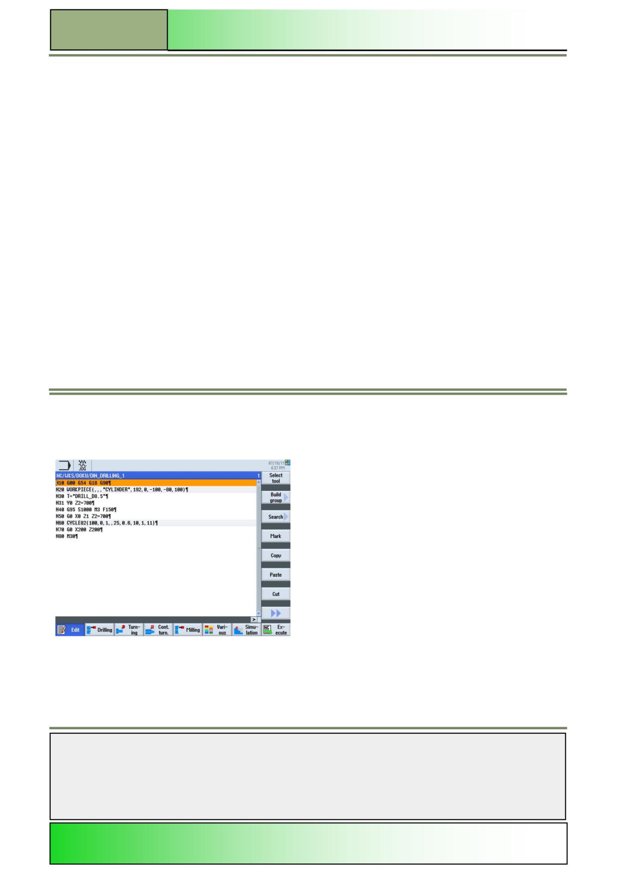
By pressing the “PROGRAM“-key on the keyboard the editor window opens directly, with the last
opened program.
If no program was loaded before, the program manager window opens instead, where you can
create or select an existing program.
- OR -
Press the “MENU SELECT“-key on the operator panel.
Press the yellow HSK 3 “Program” to change to the operating area “Program”. The last loaded
program in the editor opens (see picture below).
If not selected, press the HSK 1 “Edit“.
If no program had been opened for editing purpose, then the Sinumerik Operate opens the Pro-
gram Manager window, offering a chance to the user for choosing the desired program for edit-
ing.
For further details see module - M525 “Operating area Program Manager”.
Notes
828D/840Dsl SINUMERIK Operate
Page 11
M605
M605
Basics of programming with the programGUIDE
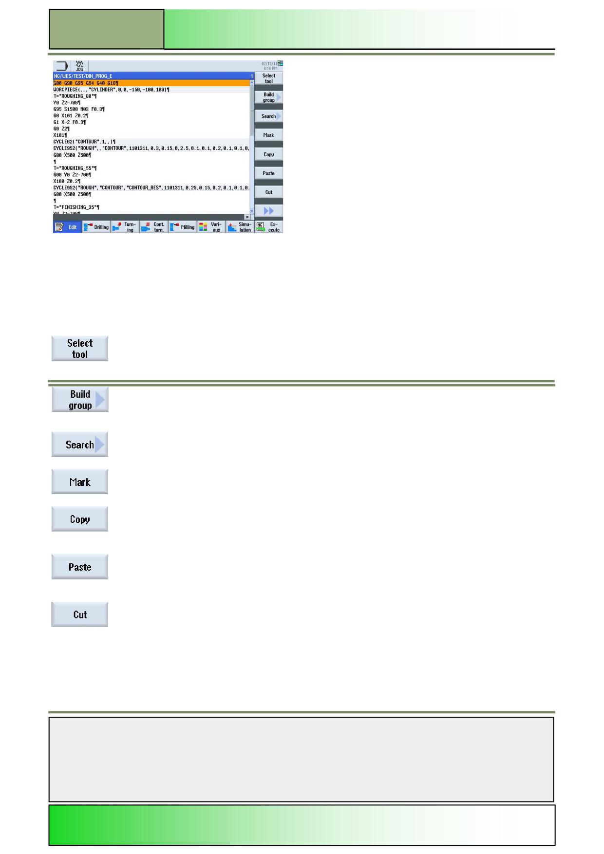
The following softkeys are available for editing a program:
Vertical softkey bar 1 and 2
Display area
Description
Under the function “Edit” HSK 1 press the VSK 1.1 “Select Tool” to open the tool selection
window.
Here you can select a tool, By pressing the VSK 1.8 “OK” you can insert the selected tool data
into the G code program.
By pressing the VSK 1.2 “Build group” you can create programme blocks into groups, this can
be useful when creating large programs.
By pressing the VSK 1.3 “Search“ you can search for any text in the current program. A search
window opens where you can enter a search string. You can continue searching afterwards.
By pressing the VSK 1.4 “Mark” you can mark one or several program blocks in order to copy
or cut (delete) them.
By pressing the VSK 1.5 “Copy” you can copy one or several program blocks to the internal
memory of the control, to paste them to a different location in the active program or to another
program.
By pressing the VSK 1.6 “Paste“ copied or cut program blocks can be inserted behind the
selected program block (actual cursor position). You can paste the block to the active program
as well as to another G code program on the NC, local drive or USB.
By pressing the VSK 1.7 “Cut” you can cut out one or several program blocks, to paste them
later somewhere in a program or to delete them. Cut program steps remain in the clipboard
and can be inserted again with the VSK 1.6 “Paste”
(see VSK 1.6 Paste“).
Notes
M605
Page 12
828D/840Dsl SINUMERIK Operate
Basics of programming with the programGUIDE
M605
Vertical softkey bar 1 and 2 continued
Display area
Description
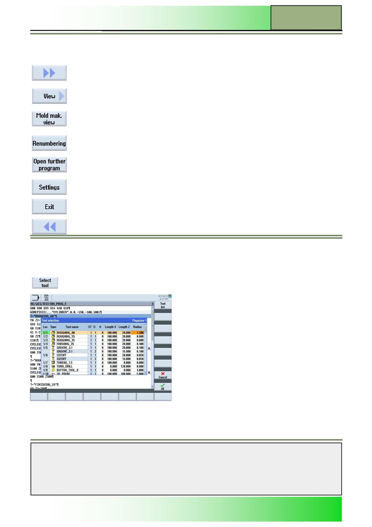
By pressing the VSK 1.8 “Extend“ the extended vertical softkey bar 2 will be displayed.
By pressing the VSK 2.1 “View” you can choose between “Close all blocks” and “Open all
blocks”.
By pressing the VSK 2.2 “Mold mak. view” you can see the simulated workpiece from a top view
as an outline drawing
By pressing the VSK 2.3 “Renumbering” you can assign new numbers for every program step in
the editor window.
By pressing the VSK 2.4 “Open further program” you can view two programs side by side.
By pressing the VSK 2.6 “Settings“ you can change the setting for the program editor.
By pressing the VSK 2.7 “Exit” you close the editor with the active program.
By pressing the VSK 2.8 “Back“ you switch back to the vertical softkey bar 1.
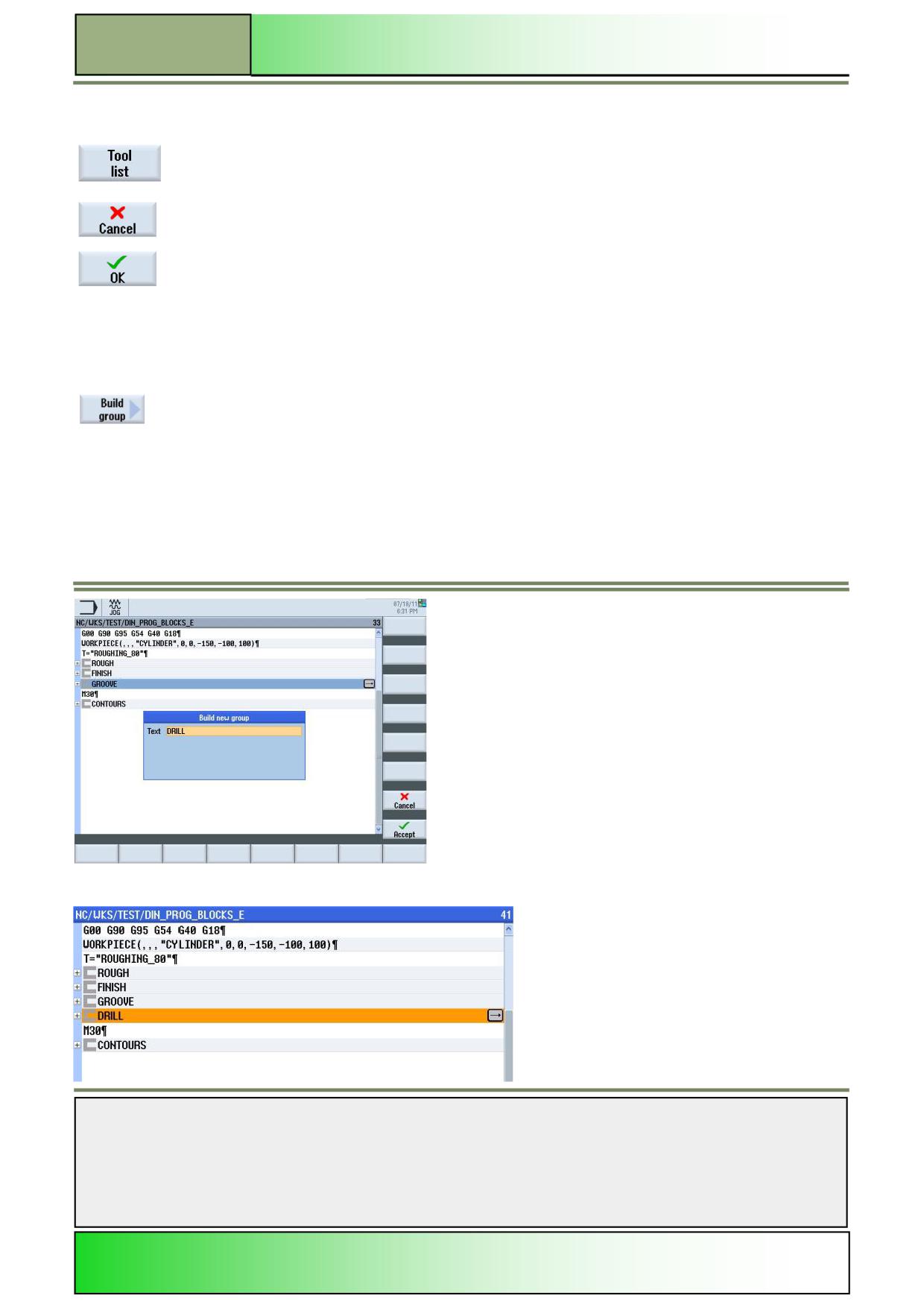
Select tool
With the function “Select tool” you can search and select a tool .
Selecting the function “Select tool”
By pressing the VSK1.1 “Select tool” the tool selection window opens like displayed below,
with the following functions available in the vertical softkey bar.
Use the “cursor up & cursor down” keys on the key board the select the required tool for the machining block.
If the required tool is not available press the VSK1 “Tool list” so that a new tool can be created .
See module - M573 “Operating area Parameter”.
Notes
828D/840Dsl SINUMERIK Operate
Page 13
M605
M605
Basics of programming with the programGUIDE
Vertical softkey bar
Display area
Description
By pressing the VSK 1 “Tool list” you are taken to the tool list.
See module - M573 “Operating area Parameter”.
With pressing the VSK 7 “Cancel” you can abort the search process.
By pressing the VSK 8 “OK“ you will load the selected tool into the machining block.
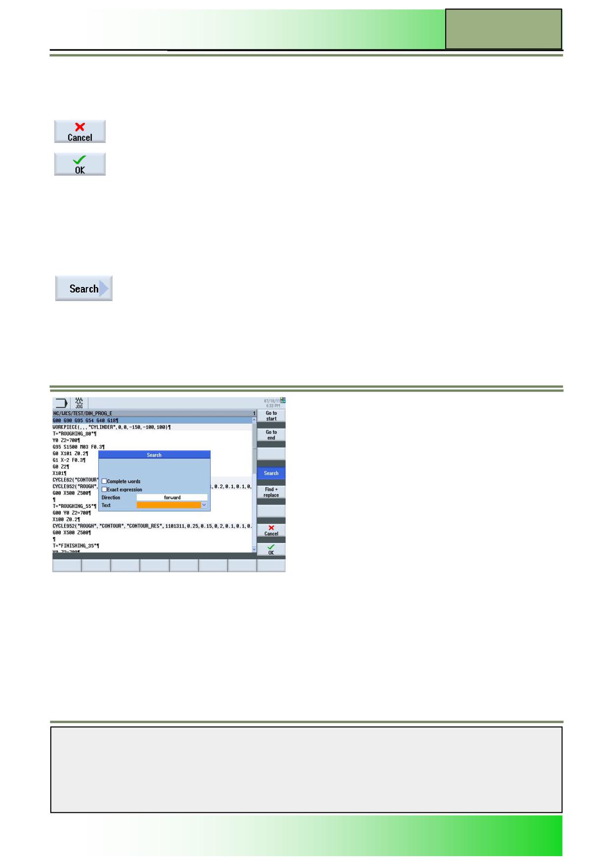
Build group
With the function “Build group” you can group similar machining blocks together .
Selecting the function “Build group”
By pressing the VSK1.2 “Build group” the build new block window opens like displayed below,
allowing you to give a name to a group
Notes
M605
Page 14
828D/840Dsl SINUMERIK Operate
Basics of programming with the programGUIDE
M605
You can now create machining blocks inside the group.
Vertical softkey bar
Display area
Description
With pressing the VSK 7 “Cancel” you can abort the search process.
By pressing the VSK 8 “OK“ you will load a new group block into the program with the name you
have chosen.
Search
With the function “Search” you can search for any text in a sequential program and even replace the text with other text.
Selecting the function “Search“
By pressing the VSK1.3 “Search” the search window opens, where you can search for any pro-
gram code in the current program.
Notes
828D/840Dsl SINUMERIK Operate
Page 15
M605
M605
Basics of programming with the programGUIDE
Vertical softkey bar
Display area
Description
By pressing the VSK 1 “Go to start” the cursor will be positioned on the first line of the pro-
gram.
By pressing the VSK 2 “Go to end” the cursor will be positioned on the last line of the program.
By pressing the VSK4 “Search” the search mask opens, where you can decide to search for
complete words, select the search direction (forward/backwards) and enter the search text.
By pressing the VSK5 “Find + replace” the “Search and replace” mask opens where you can
decide to search for complete words, select the search direction (forward/backwards), enter the
search text and enter the text you want to use for the replacement.
With pressing the VSK 7 “Cancel” you can abort the search process.
By pressing the VSK 8 “OK“ you start a search run with the above mentioned search criteria.
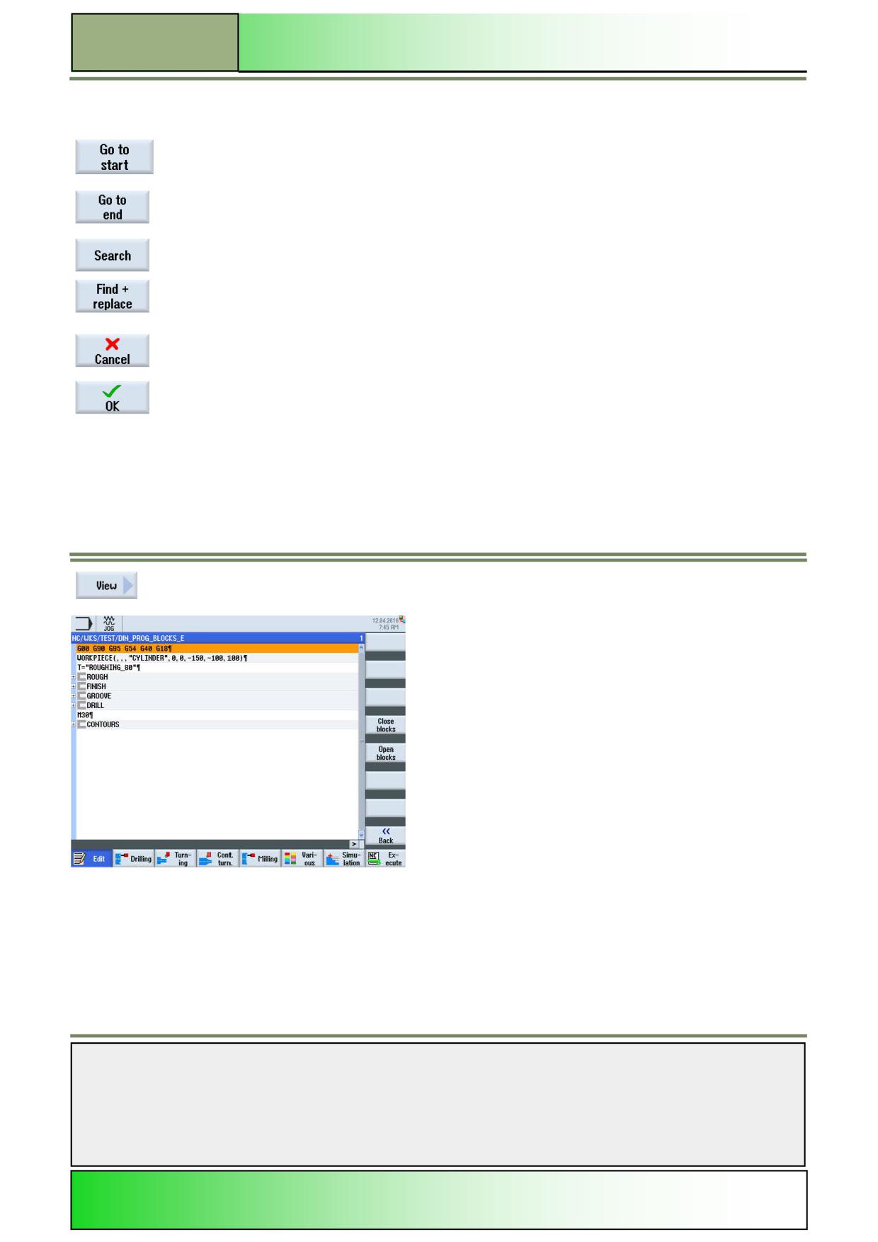
View
With the function “View” you can expand or close all “groups” that have been created in the program.
Selecting the function “View”
By pressing the VSK2.1 “View” the softkeys “Close blocks” and “Open blocks” are shown like
displayed below.
Press VSK 5 “Open all blocks”
Notes
M605
Page 16
828D/840Dsl SINUMERIK Operate
Basics of programming with the programGUIDE
M605
Vertical softkey bar
Display area
Description
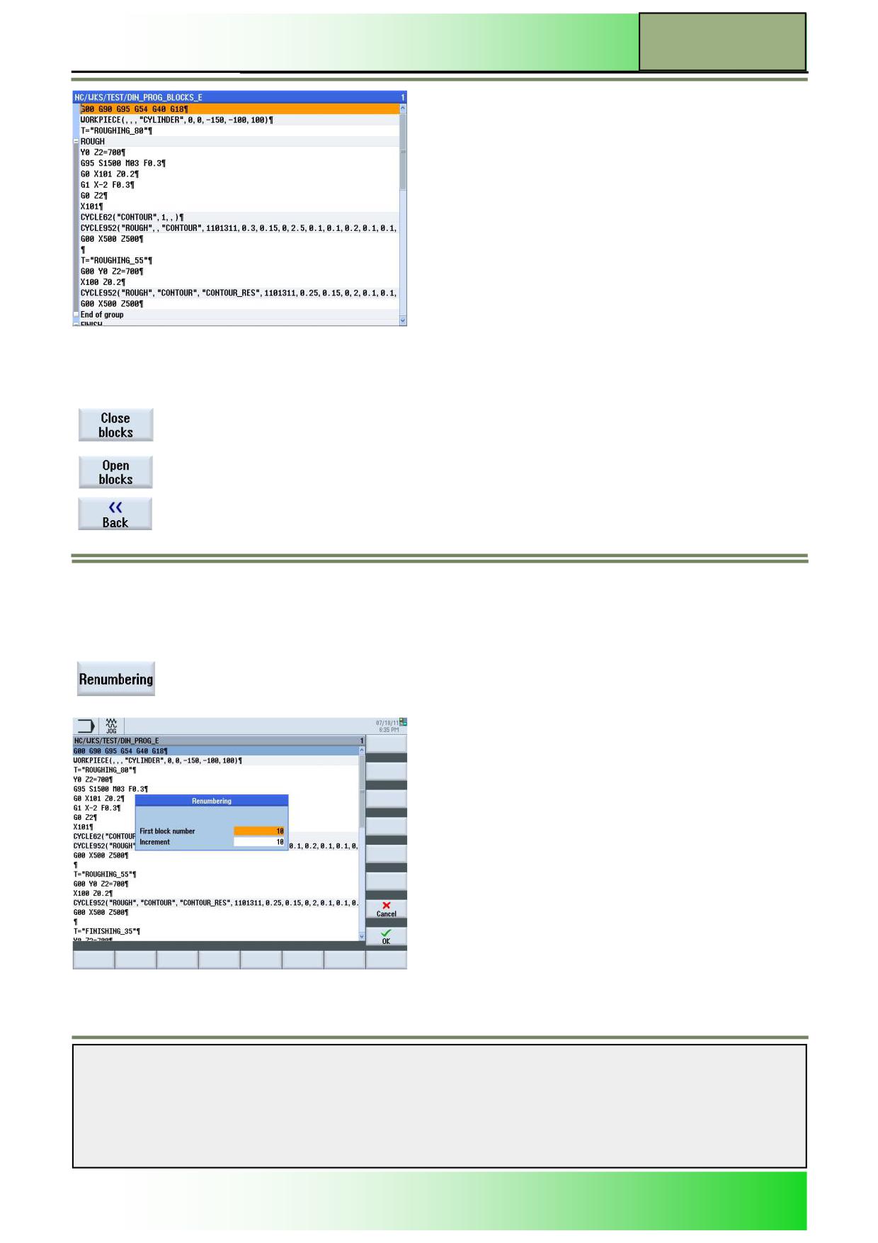
Pressing the VSK 4 “Close blocks” you can close all block in the program.
Pressing the VSK 5 “Open blocks“ you can open all block in the program
With the VSK 8 “Back” you can go back to the previous vertical softkey bar.
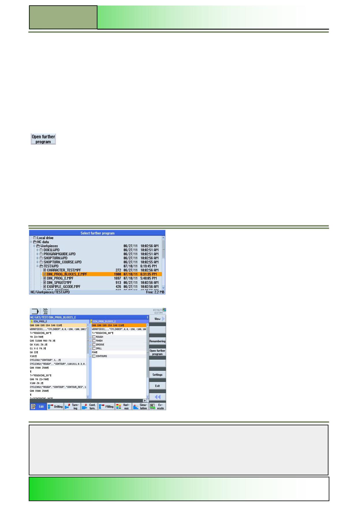
Renumbering
With the function “Renumbering” you can renumber manually the program steps in the work plan with an increment you
can select here.
Selecting the function “Renumbering“
By pressing the VSK 2.3 “Renumbering” the input window opens where you can change the
settings for the renumbering of the program blocks in the editor window.
Notes
828D/840Dsl SINUMERIK Operate
Page 17
M605
M605
Basics of programming with the programGUIDE
Parameters for “Renumbering”
Parameters
Meaning
First block number
The first block number you want to start with.
The values shown here by default can be adjusted under the function “Settings” in the input
field “First block number”.
Increment
The Increment between the program blocks.
The values shown here by default can be adjusted under the function “Settings” in the input
field “Increment”.
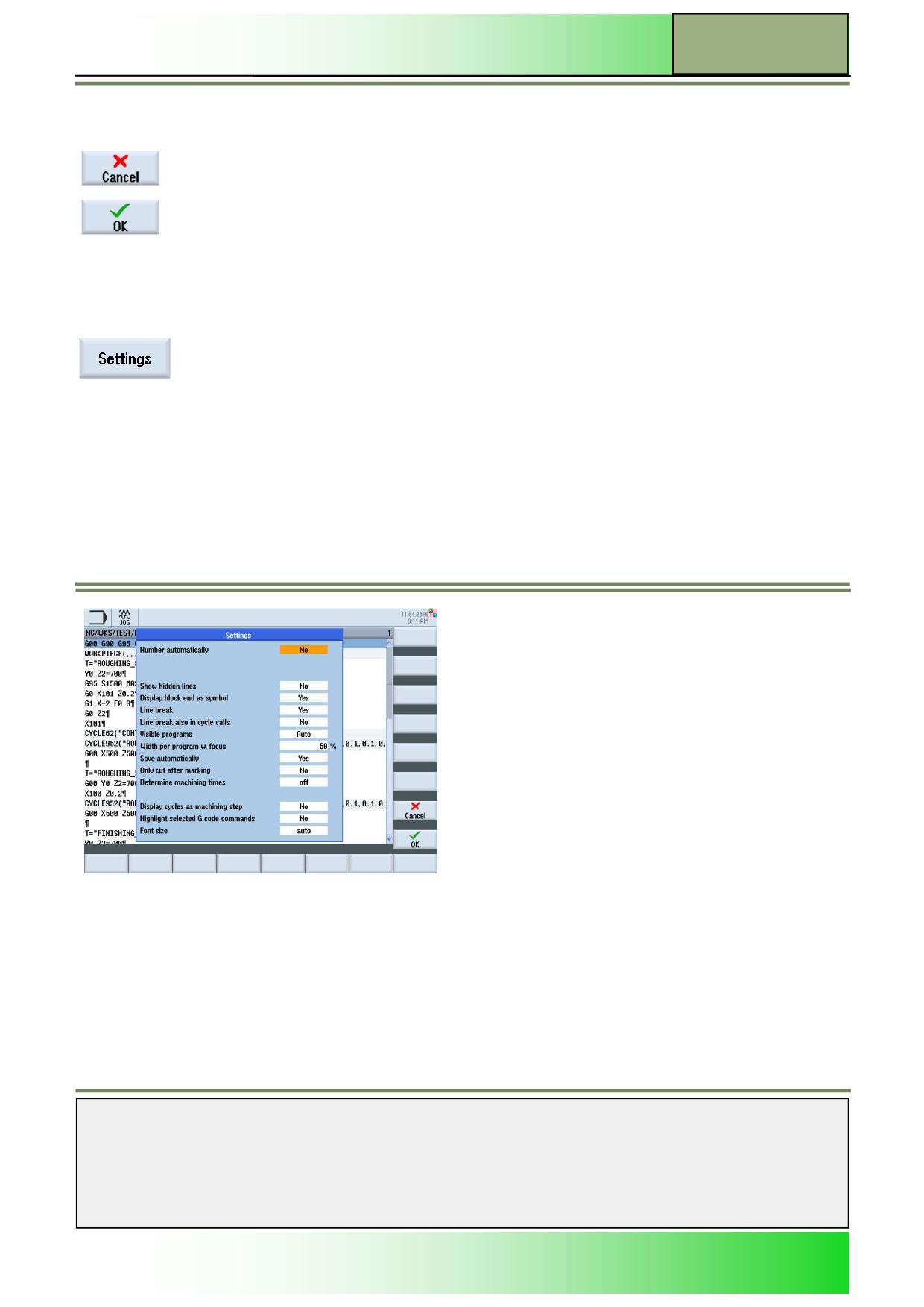
Open further programs
With the function “Open further programs” the control will show two programs side by side.
Selecting the function “Open further programs”
By pressing the VSK2.4 “Open further programs” the window opens that allows you to choose a
further program to be shown.
Use the “cursor up” or “cursor down” keys on the key board the select the required program and press VSK8 “OK”
Notes
M605
Page 18
828D/840Dsl SINUMERIK Operate
Basics of programming with the programGUIDE
M605
Vertical softkey bar
Display area
Description
With pressing the VSK 7 “Cancel” you can abort the select process.
By pressing the VSK 8 “OK“ the control will show two programs side by side, as shown above.
Settings
With the function “Settings” you can change the settings for the program editor.
Selecting the function “Settings“
By pressing the VSK 2.6 “Settings” the settings window for the program editor opens.
Notes
828D/840Dsl SINUMERIK Operate
Page 19
M605
M605
Basics of programming with the programGUIDE
Parameters for “Settings”
Parameters
Meaning
Number automatically
Program blocks will be numbered automatically.
(Yes/No)
Deactivating this parameter, hides the following two parameters too.
Show hidden lines
Show hidden line (with the ID ;*HD).
(Yes/No)
Display block end as
A symbol is displayed at the end of each block.
symbol (Yes/No)
Line break (Yes/No)
Lines are broken and wrapped around, or a horizontal scrollbar is displayed
Line break also in cycle
If the line of a cycle call becomes too long, then it is displayed over several lines, or the line is
call (Yes/No)
truncated.
Visible programs
Selects how many programs can be displayed next to one another in the editor
Width of program w. fo-
Here, you enter the width of the selected program in the editor as a percentage of the window
cus
width.
Save automatically
Changes are saved automatically without a query.
(Yes/No)
Only cut after making
The cutting of program sections is possible only when program lines have been selected or
(yes/no)
where the cursor is positioned.
determine machining
Block-by-block / off / Non-modal
times
Display cycles as ma-
The cycle calls in the G code are displayed as plain text or NC syntax.
chining step (Yes/No)
Highlight selected G
Selected G code commands or key words can be highlighted in colour
code commands
Font size
Defines the font size for the editor and the display of the program sequence
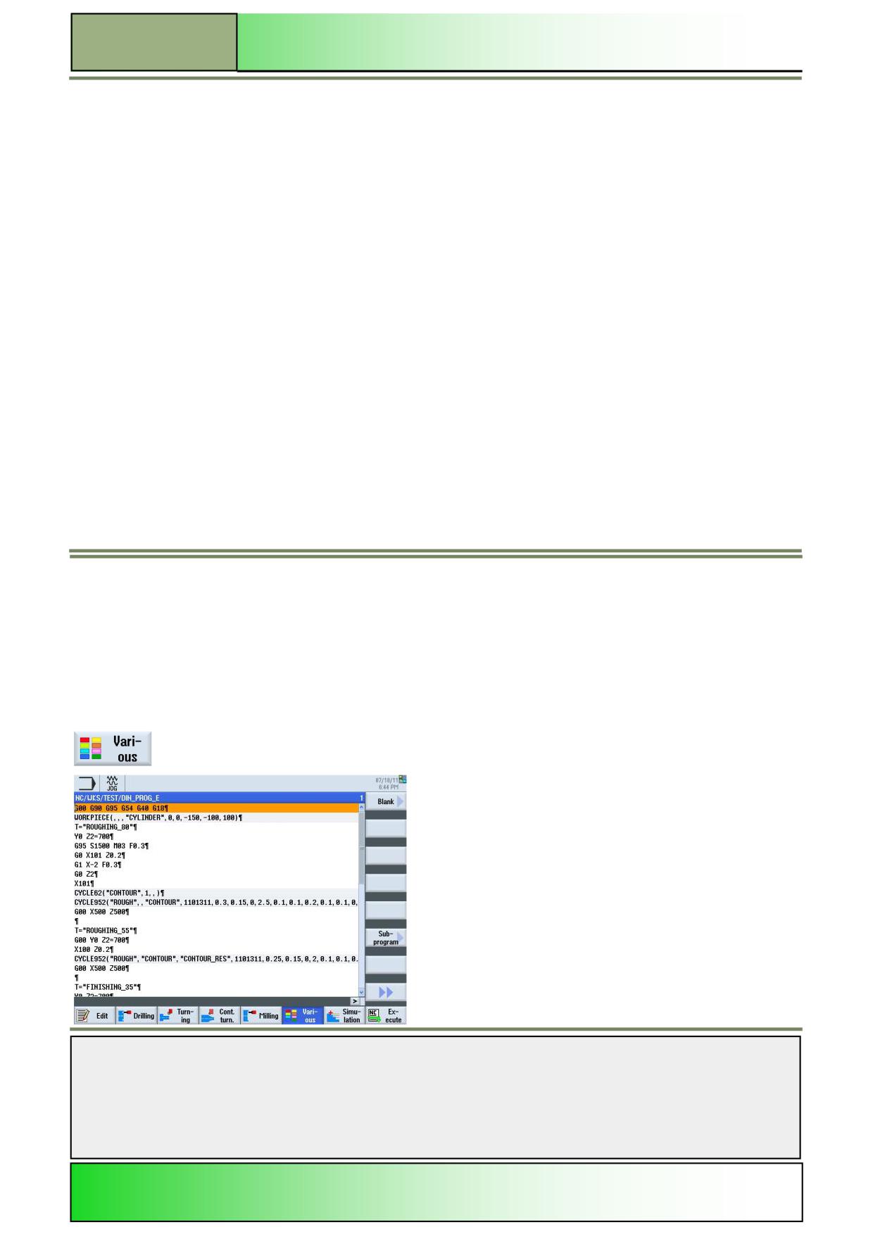
Various
Selecting the function “Various”
The function “Various” can be selected from the operating mode “JOG”, “MDA” or “AUTO” in the operating area “Program”
as follows:
Press the HSK 6 “Various“ to switch over to the function “Various”. The following functions
described are shown in the VSK-bar of the program editor.
Notes
M605
Page 20
828D/840Dsl SINUMERIK Operate
Basics of programming with the programGUIDE
M605
Vertical softkey bar 1 and 2
Display area
Description
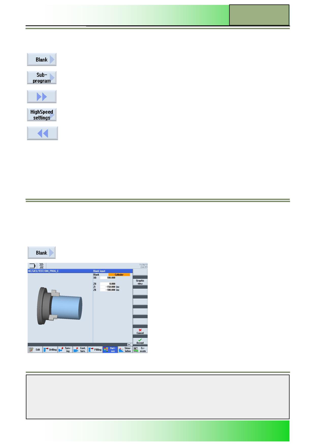
By pressing the VSK 1.1 “Blank“ an input mask opens where you can change the settings for the
blank.
By pressing the VSK 1.6 “Subprogram” the input mask for loading a subprogram to the main
program opens.
By pressing the VSK 1.8 “Extend“ the vertical softkey bar 2 opens.
By pressing the VSK 2.1 “HighSpeed settings“ the input mask for adjusting the settings for the
optimal speed in relation to the machining method opens.
By pressing the VSK 2.8 “Back“ you switch back to the vertical softkey bar 1.
Blank
The blank is needed for the simulation and the simultaneous recording. A realistic simulation is only possible with a blank,
that represents the actual blank dimensions as close as possible.
The shape (Block centred, Pipe, Cylinder or N-corners) and dimensions of the blank must be defined.
Selecting the function “Blank“
By pressing the VSK 1.1 “Blank” the blank input window opens.
Notes
828D/840Dsl SINUMERIK Operate
Page 21
M605

M605
Basics of programming with the programGUIDE
Parameters for the “Blank”
Parameter
Meaning
Blank
The following blank forms can be selected:
Block centred
Pipe
Cylinder
N corner
ZA
Initial dimension
ZI (abs/inc)
Final dimension related to ZA (absolute or incremental)
ZB (abs/inc)
Machining dimension
Parameter
Meaning (continuation)
XA
Outside diameter (only with pipe or cylinder)
XI
Inside diameter (absolute or incremental)
N
Number of edges (only with N corner)
SW
Width across flats (only with N corner)
W
Width of blank (only with Block centred)
L
Length of blank (only with Block centred))
5.3.3 Changing the graphical view on the blank
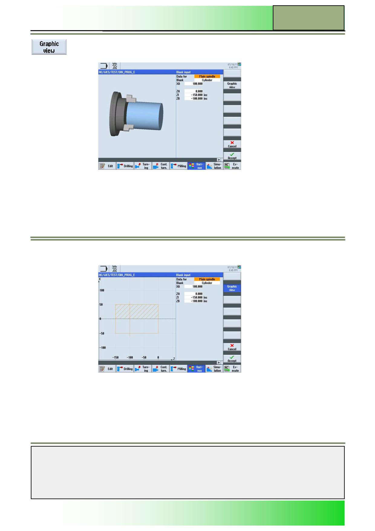
The graphic view of the blank and cycles can be changed under the function “Various” (blank), as well as under the technolo-
gy cycles Drilling”, “Turning” and “Milling”, by pressing the VSK 2 “Graphic view”.
Help pictures and animations are only displayed if the VSK 2 “Graphic view” is deselected.
You can change the graphic view of the blank as follows:
1.
In the operating area “Program” press the HSK 1.6 “Various”.
2.
Press the VSK 1.1 “Blank” to open the input mask for the blank settings.
Notes
M605
Page 22
828D/840Dsl SINUMERIK Operate
Basics of programming with the programGUIDE
M605
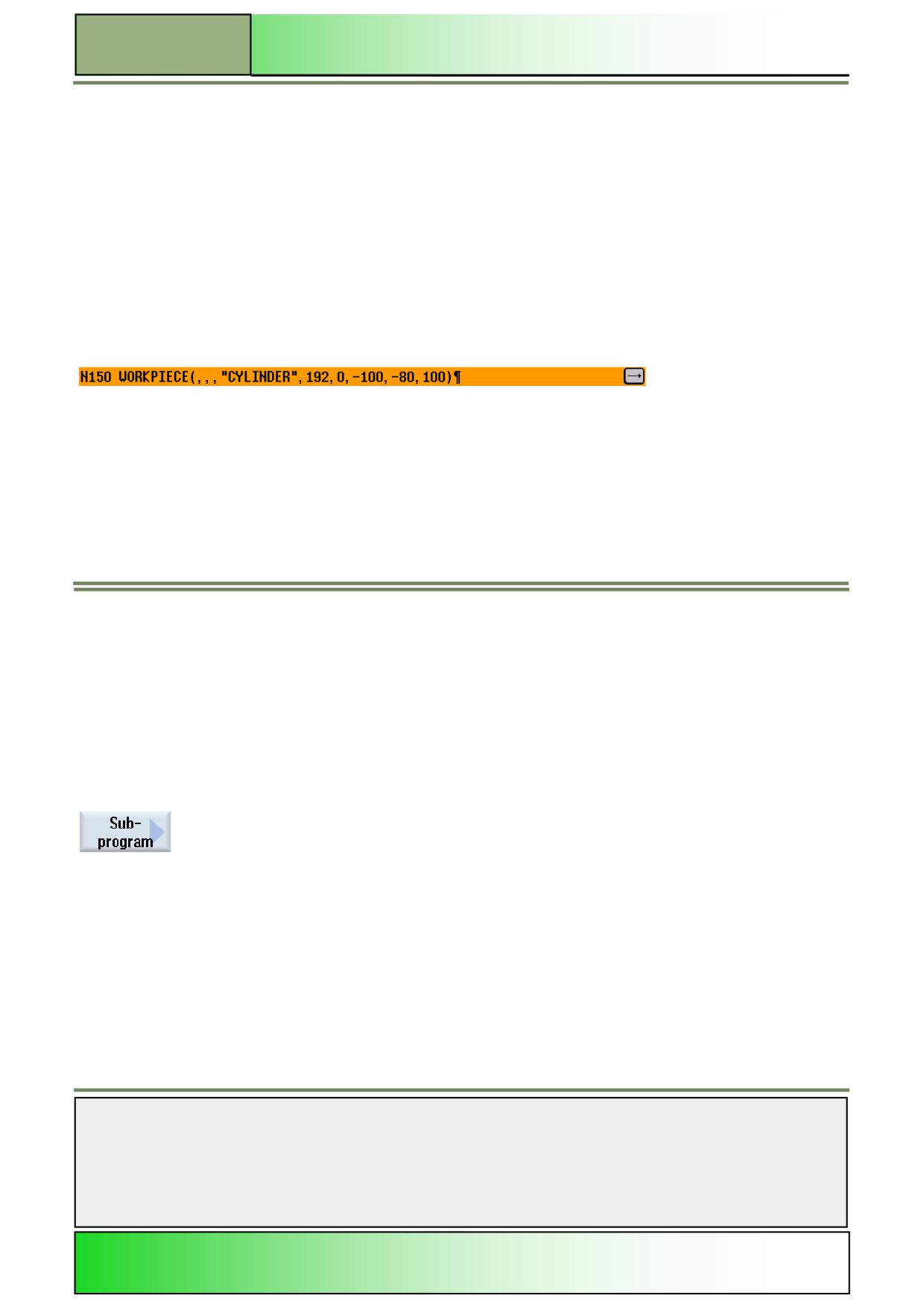
Activate or deactivate the VSK 2 “Graphic view” to switch between a:
3D view/side view
and an outline drawing.
Notes
828D/840Dsl SINUMERIK Operate
Page 23
M605
M605
Basics of programming with the programGUIDE
Changing the settings for the blank
1.
In the operating area “Program” press the HSK 1.6 “Various”.
2.
Press the VSK 1.1 “Blank”.
The setting window for the blank opens.
3.
Optionally change the help graphic view on the blank by pressing the VSK 2 “Graphic view”.
4.
Enter the parameters for the blank in the corresponding input fields.
5.
Confirm your inputs by pressing the VSK 8 “Accept” or abort with pressing the VSK 7
“Cancel”.
A new program block “WORKPIECE” is inserted into the Work plan (see picture below)
Subprogram
If you require the same machining steps in the programming of different workpieces, you can define these machining steps
in a separate subroutine. You can then call this subroutine in any program.
Identical machining steps therefore only have to be programmed once. ShopTurn does not differentiate between main pro-
gram and subprogram. This means that you can call a "standard" sequential ShopTurn or G code program as subprogram
from another G code program. In this subprogram, you can also call another subprogram. The maximum nesting depth is 8
subroutines.
If you want to call a sequential ShopTurn program as a subroutine, the program must already have been calculated once
(load or simulate program in “AUTO” mode). This is not necessary for G code
subroutines.
The subroutine must always be stored in the NCK main memory (in a separate directory "XYZ" or in the "ShopTurn", "Part
programs", "Subprograms" directories).
If you want to call a subprogram located on another drive, you can use the G code command "EXTCALL".
Note:
Please note that, when a subprogram is called, ShopTurn evaluates the settings in the program header of the subroutine.
These settings also
remain active even after the subprogram has ended.
If you wish to activate the settings from the program header for the main program again, you can make the settings again in
the main program after calling the subprogram.
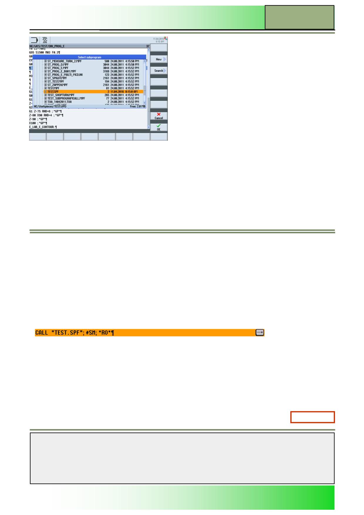
Selecting the function “Subprogram”
By pressing the VSK 1.6 “Subprogram”, the input window for calling up a subprogram opens.
Notes
M605
Page 24
828D/840Dsl SINUMERIK Operate
Basics of programming with the programGUIDE
M605
Subprogram call
1.
In the operating area “Program“ press the HSK 1.6 “Various“.
2.
Press the VSK 1.6 ”Subprogram”.
The input window for the subprogram call opens.
3.
Enter the directory path to the subprogram and the name of the subprogram in the input mask.
Press the VSK 8 “Accept” to confirm your inputs or press the VSK 7 “Cancel” to abort.
A new program block “Execute” with the subprogram path is inserted into the work plan (see
picture below).
M605: END
Notes
828D/840Dsl SINUMERIK Operate
Page 25
M605

M605
Basics of programming with the programGUIDE
Notes
M605
Page 26
828D/840Dsl SINUMERIK Operate
M509
Loops, jumps, repetitions and messages
Sinumerik
Operate
Module Description:
This module describes the possibilities of program jumps, repetitions of certain sections of the pro-
gram and the application of variables for calculation.
Module Objective:
In this module you learn to manipulate the regular block-by-block program execution and
to use R-variables. The use of the codes is equally possible for both milling and turning.
Content:
Program jumps and skip blocks
Program section repeat
Calculation variables R
Program loops
Programmable messages
This document was produced for training purposes.
828D/840Dsl SINUMERIK Operate v4.7
Page 1
M509
Siemens assumes no responsibility for its contents.
M509
M509
Page 2
828D/840Dsl SINUMERIK Operate
Loops, jumps, repetitions and messages
M509
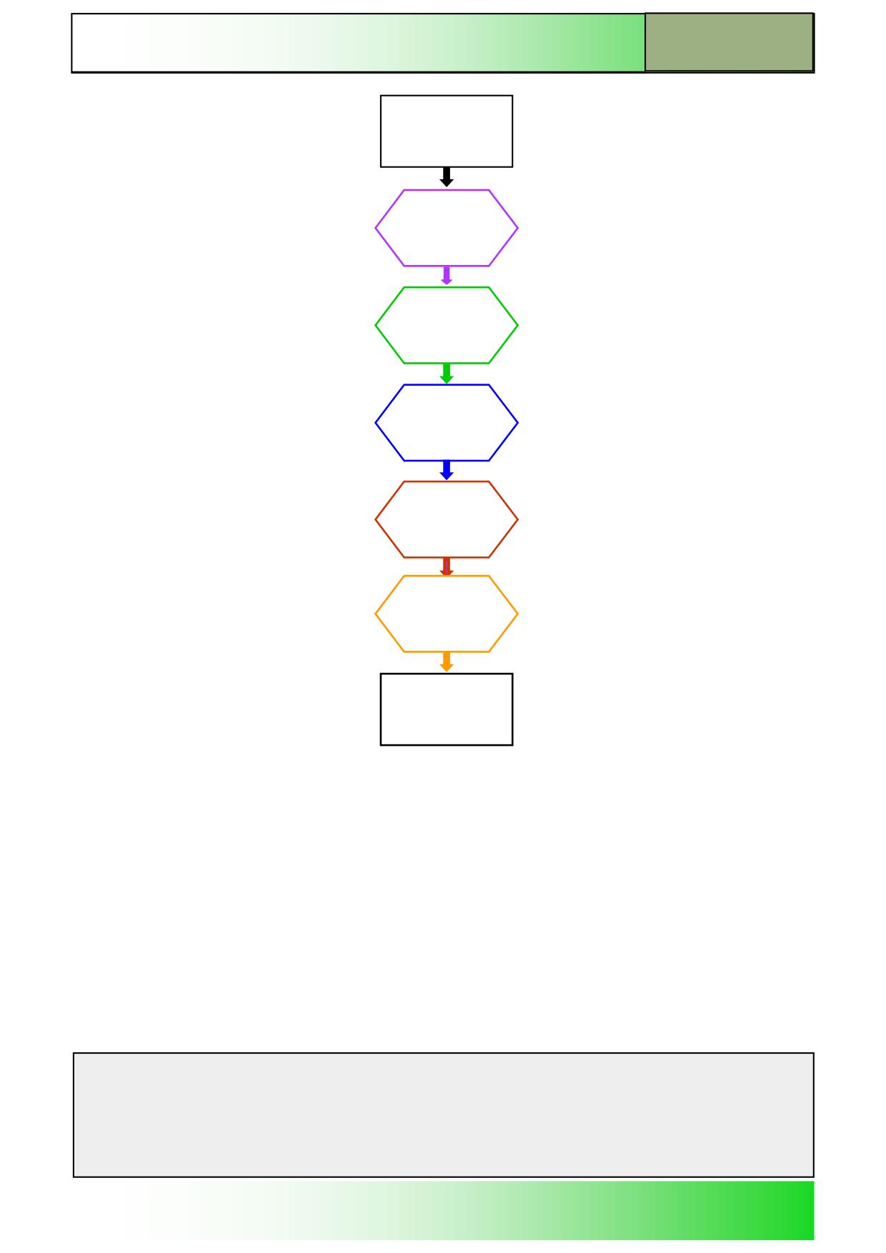
Loops, jumps,
Repetitions and
messages:
START
Program
jumps and
skip blocks
Program
section
repeat
Calculation
variables R
Program
loops
Programmabl
e messages
Loops, jumps,
Repetitions and
messages:
END
Notes
828D/840Dsl SINUMERIK Operate
Page 3
M509

M509
Loops, jumps, repetitions and messages
Program jumps and skip blocksProgram jumps
Porgram jumps
In practice it is often necessary to interrupt the block-by-block execution of the program and to jump to another part of the
program.
Certain number of blocks should not be executed by the control unit for instance when testing a program.
Since the control does not recognize the block numbers, the jump destination must always be identified by markers (labels).
The MARKER may be any chain of characters followed by a colon, however, the chain of characters must not be identical
to any command of the control unit.
Example:
N100 LBL8
If for instance a section of the program is to be left out, the jump instruction GOTOF can be used.
This instruction searches for the jump destination only in the forward direction of the program. The program will then be
continued from there on in the normal manner.
N10 G18 G54 G64 LIMS=3000
N20 G00 X200 Z300
N30 GOTOF LBL8
Forward jump to the marker „LBL8:“
N40 T1;
Roughing tool
N50 G96 S160 F0.2 M4 D1
The blocks N40 to N90 will be ignored
N60 G00 X82 Z0.2 M8
N70 G01 X-1.6
N80 Z2
The program will be continued as from
N90 G00 X200 Z300
block N100
N100 LBL8:
N110 T2; Finishing tool
N120 G96 S200 F0.15 M4 D1
N130 G00 G42 X0 Z2 M8
N140 G01 Z0
To initiate a backward jump in the program the instruction GOTOB must be used.
Caution!
The backward jump will result in an endless loop if the number of runs is not limited.
Note:
Markers will be ignored by the control unit if there is no jump command to the marker. The execution of the program will not
be affected under any circumstances by a marker without a jump instruction.
Notes
M509
Page 4
828D/840Dsl SINUMERIK Operate
Loops, jumps, repetitions and messages
M509
Deletion blocks
There is another way of optionally including or excluding certain parts of the program by excluding explicitly marked blocks.
The program blocks intended for optional exclusion are marked simply by a preceding / (slash).
Example:
/N200 CYCLE96(24,-30,“A“,3)
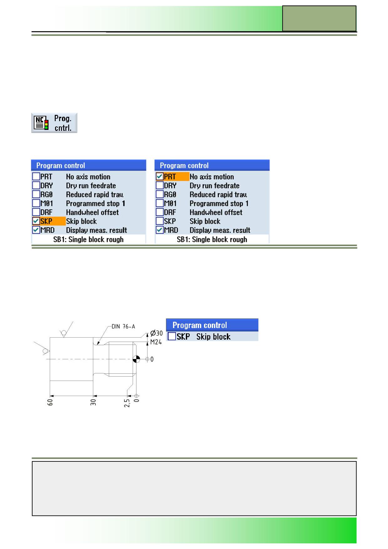
Simply by activating the option "SKP Skip block" (after pressing the VSK 4 "Prog. Cntrl." (Program control) in the automatic
mode) all blocks marked with a "/" will be ignored by the control unit.
If this option is deactivated, the marked blocks will be executed in the same manner as all others.
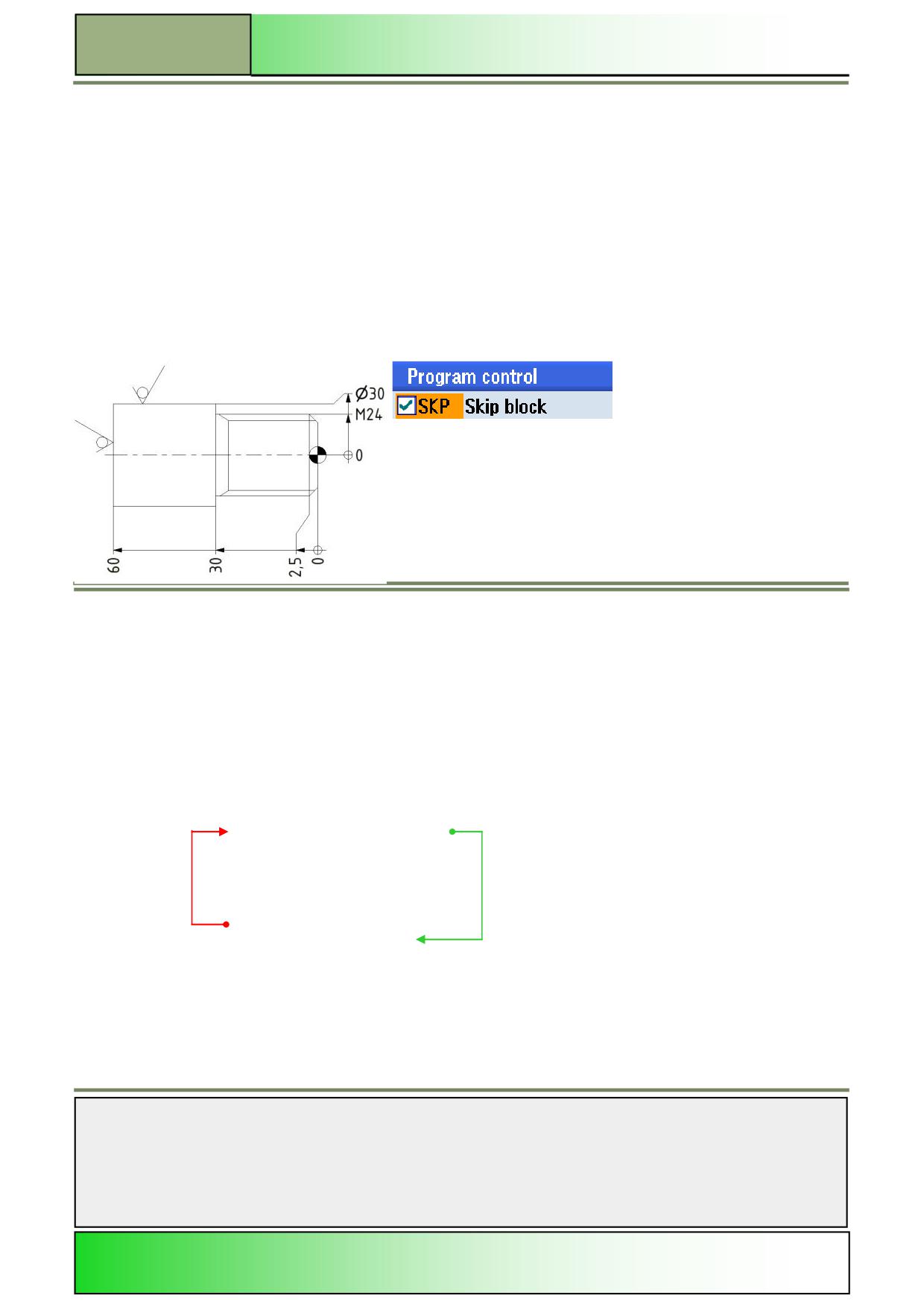
SKP is activated; in the program mode the
SKP is deactivated; the control also exe-
blocks with a preceding slash will be ig-
cutes the blocks with a preceding slash.
nored.
The following example is used to illustrate the usage of optional blocks:
Studs with a thread size M24 are to be produced, some of which have a thread relief as per DIN 76-A. You will now create a
single program and manipulate the machining using the optional “skip block” technique.
Stud with thread relief
The function “Skip block” is deactivat-
ed; optional blocks will be executed.
Block N200 will be executed.
Notes
828D/840Dsl SINUMERIK Operate
Page 5
M509
M509
Loops, jumps, repetitions and messages
Program section without roughing
N130 T2
; Finishing tool
N140 G96 S200 F0.15 M4 D1
N150 G00 G42 X14 Z2.5 M8
N160 G01 X24 Z-2.5
; Finishing
N170 Z-30
N180 X32
N190 G00 G40 Z2
/N200 CYCLE96(24,-30,"A",3)
; Optional block thread relief
N210 G00 X200 Z300
N220 T4
; Thread cutting tool
N230 G97 S1500 M3 M8 D1
N240 CYCLE97(3,24,0,-27,24,24,10,2,1.84,0.03,30,0,6,3,3,1,2)
N250 G00 X200 Z300
N260 M30
Stud without a thread relief
The function “Skip block” is activated;
optional blocks will not be executed.
Block N200 is not executed.
Program section repeat
If a certain number of NC-blocks is to be repeated at another part of the program, the instruction REPEAT is available.
The instruction requires a start marker as a jump destination. An end marker can possibly be included for a better overview.
The end marker is only really necessary if the repeat instruction is not directly in the succeeding block of the part of the
program to be repeated.
Example without end marker (single repeat):
N30 T1;
Roughing tool
N40 G96 S160 F0.2 M4 D1
N50 G00 X82 Z0 M8
N60 G01 X-1.6
N70 Z3
N80 G00 X80; blank dimension
N90 LBL10:
Single repetition of the
N100 G00 G42 X=IC(-4) Z1
program section
Jump to start
N110 G01 Z-20
N120 X=IC(6)
N130 G00 G40 Z4
N140 G01 X=IC(-6)
Program continuation
N150 REPEAT LBL10
After the blocks N90 to N140 have been repeated the program will be continued with block N160.
Note:
The program section (N90 to N140) is already executed once during the normal run of the program. With the “REPEAT”-
instruction this will be carried out a second time.
Notes
M509
Page 6
828D/840Dsl SINUMERIK Operate

Loops, jumps, repetitions and messages
M509
Example with end label and multiple repeat:
N80 G00 X80; blank dimension
N90 LBL12:
N100 G00 G42 X=IC(-4) Z1
N110 G01 Z-20
N120 X=IC(6)
N130 G00 G40 Z4
N140 G01 X=IC(-6)
N150 EBE12:
Repetition
N160 G00 X200 Z300
N170 T7;
Roughing tool 2
4 times
N180 G96 S180 F0.25 M4 D1
N190 G00 G42 X74 Z4 M8
N200 REPEAT LBL12 EBE12 P4
N210 G00 X200 Z300
With the instruction “REPEAT LBL12 EBE12 P4” the program blocks N90 to N150 are repeated a total of 4 times. After that
the program will be continued with block N210.
Note:
Make sure at all times that the markers are written correctly. The control unit treats these labels as a character chain, an
Notes
828D/840Dsl SINUMERIK Operate
Page 7
M509

M509
Loops, jumps, repetitions and messages
Calculation variables R
Calculation variables provide a large number of means for flexible programming of the numerical values of instructions.
In the program no actual values are assigned to the addresses, instead variable numbers are assigned to which the respec-
tive values have been assigned previously.
Exception: The addresses “N”, “G” and “L” can be programmed with an
“R variable”.
Normally the variables “R0” to “R99” are available.
Control specifically that this number can also be set to a greater number.
The “R variables” can be assigned with values in the range of 8 places and a decimal point as well as a sign.
Example:
± 0.000 0001 to ± 9999 9999
The value assignment to the variables can be achieved manually in the variable list, automatically in the program or by pro-
grammed calculation operations.
In the following editor extracts the two variants of programming the address values can be compared.
Addresses directly with values:
Indirect address values by means of “R
variables”:
N10 G18 G54 G64 LIMS=3000
N10 G18 G54 G64 LIMS=3000
N20 G00 X200 Z300
N20 G00 X=R1 Z=R2
N30 T1;
Roughing tool
N30 T1;
Roughing tool
N40 G96 S160 F0.2 M4 D1
N40 G96 S=R10 F=R11 M4 D1
N50 G00 X82 Z0 M8
N50 G00 X=R3+2 Z=R0 M8
N60 G01 X-1.6
N60 G01 X-1.6
N70 Z3
N70 Z3
N80 G00 X80;
Raw dimension
N80 G00 X=R3;
Raw dimension
N90 LBL12:
N90 LBL12:
N100 G00 G42 X=IC(-4) Z1
N100 G00 G42 X=IC(R4) Z1
N110 G01 Z-20
N110 G01 Z=R5
N120 X=IC(6)
N120 X=IC(R6)
N130 G00 G40 Z4
N130 G00 G40 Z4
N140 G01 X=IC(-6)
N140 G01 X=IC(-R6)
N150 EBE12:
N150 EBE12:
Note:
The respective numerical values that have been assigned to the variables “R0” to “R11” will be found in the variable list on
the following page.
Notes
M509
Page 8
828D/840Dsl SINUMERIK Operate
Loops, jumps, repetitions and messages
M509
Value assignment manually: (via variable list)
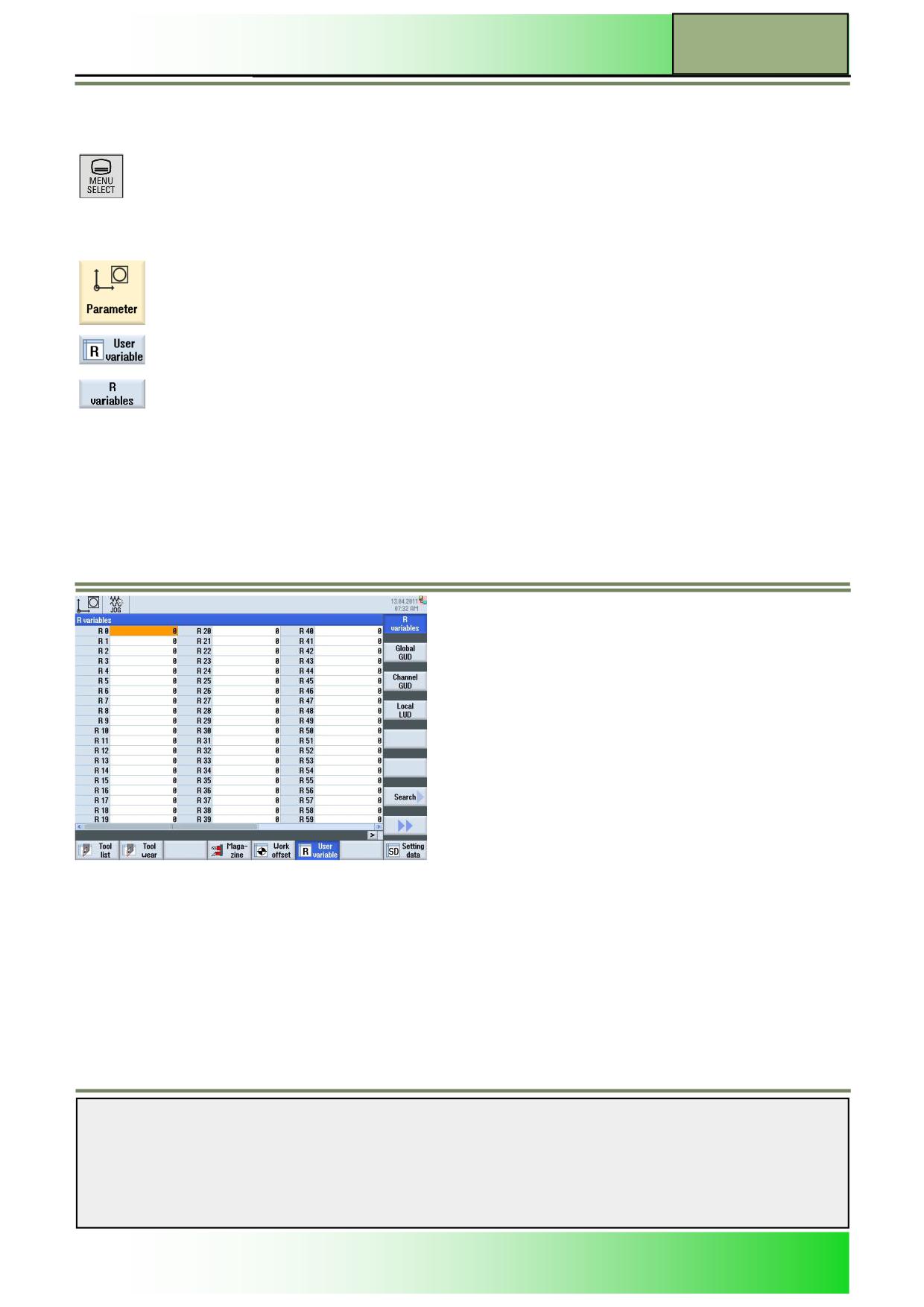
The “R-variables”-window can be accessed via:
1. Press the button “MENU SELECT” on the
operator panel (OP).
2. The yellow horizontal and vertical softkey-bar
appears.
3. Press the yellow HSK 2 “Parameter”.
4. Press the HSK 6 “User variable”
5. If not selected before press the VSK 1 “R variables“.
6. The “R variables”-window opens up (like dis-
played below).
7. Assign a “R variable“-value.
Note:
The values of the variables must have been assigned before they are called in the program.
Value assignment in the program block:
In an NC-block several assignments can be made, however, not in blocks with other instructions.
N1;
*** Value assignment to the R-Variable ***
N2 R0=0 R1=200 R2=300
N3 R3=80 R4=-4 R5=-20 R6=6
N4 R10=160 R11=0.2
N5;
*** End of value assignment ***
Notes
828D/840Dsl SINUMERIK Operate
Page 9
M509

M509
Loops, jumps, repetitions and messages
Value assignment by means of calculation operations:
The use of calculation variables and their linkage in mathematical functions provides many means in programming.
Since the control evaluates a certain number of blocks in advance, errors can occur when mathematical operations are car-
ried out.
For this reason program the code “STOPRE” before the calculation of variables as shown in block N120. This command
stops the advance evaluation until all stored blocks have been completed.
N10 G18 G54 G64 LIMS=3500
N20
N30 R1=20 R2=50
; Value assignment
N40
N50 STOPRE
; Advance evaluation stop
N60
N70
; Calculation instruction
N80 R10=R1+R2
; R10 derives from R1+R2 (value 70)
N90 R11=SIN(45)
; R11 results in the sin of 45° (value 0.707)
N100 R12=R1+2
; R12 results in 22
N110 R13=R1
; R13 takes over the value of R1
N120 R13=R13/10
; The new R13 derives from the old
N130
; R13 divided by 10 (value 2)
Note:
The editor extract shown here demonstrates only a small selection of the possible calculation operations.
Refer to the manual of your control unit regarding the available functions.
In order to maintain a clear overview it is sensible to describe a variable only once.
For the use of the calculation functions the usual mathematical rules apply.
Program loops
Contrary to the “REPEAT” command “GOTOB/GOTOF“ provides the programmer with greater flexibility.
The commands GOTOB/GOTOF can be used along with conditional statements for evaluation of program loops. If a condi-
tion is satisfied, a certain sections of the program will be repeated.
In this case the number of loop executions is counted and evaluated with the instruction “IF”.
The following comparison operators can be evaluated with “IF”:
==
equal
<>
not equal
<
larger than
>
smaller than
<=
larger or equal
>=
smaller or equal
Notes
M509
Page 10
828D/840Dsl SINUMERIK Operate

Loops, jumps, repetitions and messages
M509
N30 T1
; Roughing tool
N40 R20=0
; Counter = 0
N50 G96 S160 F0.2 M4 D1
N60 G00 X82 Z0 M8
N70 G01 X-1.6
N80 Z3
N90 G00 X80
; Blank dimension
N100 LBL14:
N110 STOPRE
; Advance evaluation stop
N120 R20=R20+1
; Counter is increased by 1
N130 G00 G42 X=IC(-4) Z1
N140 G01 Z-20
N150 X=IC(6)
N160 G00 G40 Z4
N170 G01 X=IC(-6)
N180 IF R20==4 GOTOF LBL16
; Comparison of the counters
N190 GOTOB LBL14
; Jump back to the marker LBL14
N200 LBL16:
Example:
Explanation of the situation directly after the program start:
N40
Counter for number of repeats set to 0
N100
First run without jump instruction
N120
Counter increases to 1
N130 to N170
technological motion sequence
N180
Comparison operation:
Counter is not = 4, hence carry on to block N190
N190 J
ump back to block N100, the second run starts
Situation in the fourth run:
N120 Counter receives the value 4
N180 The counter comparison is positive, hence jump to marker LBL16:
Programmable messages
Certain information that appears on the display while programs are being executed could be of special interest to the opera-
tor of the machine.
With the code MSG(“character chain“) a message can be programmed such that it will appear on the screen while the pro-
gram progresses.
Example:
The message programmed in block N30 will be displayed as shown below (Monitor extract).
Notes
828D/840Dsl SINUMERIK Operate
Page 11
M509

M509
Loops, jumps, repetitions and messages
N10 G18 G54 G64 LIMS=3000
N20 G00 X200 Z300
N30 MSG("Caution, jump to finishing operation!")
N40 GOTOF LBL18
N50 T1
; Roughing tool
N60 G96 S160 F0.2 M4 D1
N70 G00 X82 Z0.2 M8
N80 G01 X-1.6
N90 Z2
N100 G00 X200 Z300
N110 LBL18:
N120 T2
; Finishing tool
N130 G96 S200 F0.15 M4 D1
N140 G00 G42 X0 Z2 M8
N150 G01 Z0
N160 X78 CHR=1
N170 Z-20
N180 X82
N190 G00 G40 X200 Z300
The display will remain until a newly programmed message replaces it or the existing one is cancelled.
The message can be cleared using the code “MSG(““)” or by means of the end of program M30.
M509: END
Notes
M509
Page 12
828D/840Dsl SINUMERIK Operate
M634
Turning with programGUIDE
Sinumerik
Operate
Module Description:
This module explains the programming of a simple turning example with the programGUIDE in Shop-
Turn, by means of different turning cycles.
Module Objective:
Working through this module you become familiar with the technology “Turning” by pro-
gramming a G code program with the programGUIDE in ShopTurn.
Content:
Simple programming example
This document was produced for training purposes.
828D/840Dsl SINUMERIK Operate v4.7
Page 1
M634
Siemens assumes no responsibility for its contents.
M634
M634
Page 2
828D/840Dsl SINUMERIK Operate
Turning with programGUIDE
M634
Turning
programGUIDE:
START
Simple
programming
example
Turning
programGUIDE:
END
Notes
828D/840Dsl SINUMERIK Operate
Page 3
M634
M634
Turning with programGUIDE
Simple programming example
Creating a new programGUIDE program
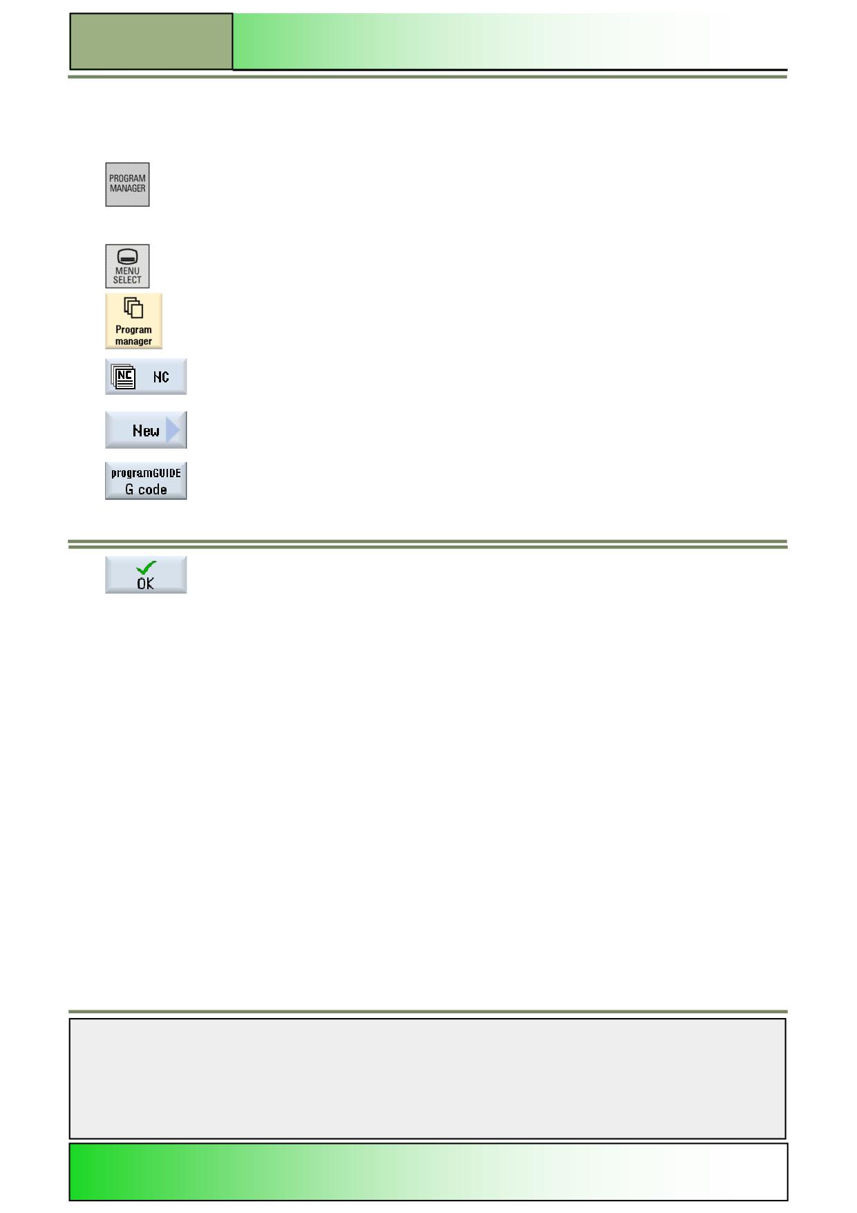
A new G code program can be created from within the operating modes “JOG, “MDA” and “AUTO” as follows:
1.
Press the “Program Manager”-key on the keyboard.
The program manager will be opened directly.
- OR -
1.
Press the “MENU SELECT”-key on the operator panel.
Press the yellow HSK 1.4 “Program Manager”.
The program manager window opens.
2.
Select a drive where you want to create the program (“NC”, “Local drive”, “USB”), by pressing a
horizontal softkey.
3.
Press the VSK 2 “New“.
The vertical softkey bar with functions for creating new programs opens.
4.
Press the VSK 4 „programGUIDE G code“ to open the input mask for creating a new G code
program.
Select “Main program MPF”.
5.
Assign a name for the program and confirm by pressing VSK 8 “OK”.
The control loads the program to the “Editor” operating area and opens the input screen for the
program
The editor window for entering G code commands opens.
Description:
A simple ShopTurn program (pin) to be programmed with the help of stock removal cycle calls
Objective:
A new ShopTurn program should be created and opened in the editor.
The program header, Stock Removal1, Stock Removal1 and Stock Removal2 cycles and end of the program to be pro-
grammed and subsequently simulated.
The following tools and technology data are required for programming:
Tool and technology da- ROUGHING_80A
ta:
( F 0.250 mm/rev, S 240 m/min)
FINISHING_35A
( F 0.150 mm/rev, S 250 m/min)
Workpiece data:
Blank: Ø 100 x 130 mm
Notes
M634
Page 4
828D/840Dsl SINUMERIK Operate
Turning with programGUIDE
M634
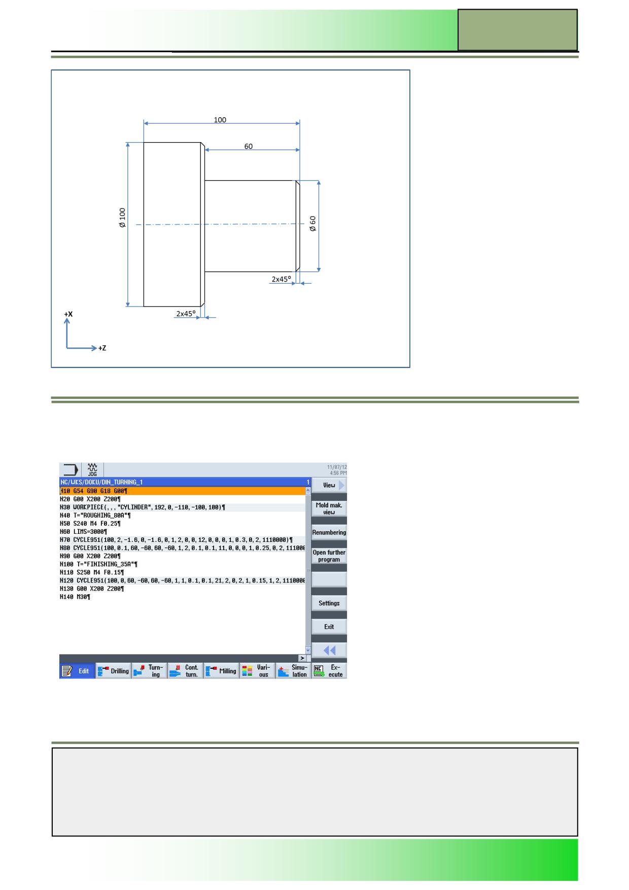
Programming example: Spigot
The G code program shown below is to be programmed:
Create a new G code programGUIDE-program in ShopTurn, like described in this module.
Call the program for example "DIN_TURNING_1.MPF".
Notes
828D/840Dsl SINUMERIK Operate
Page 5
M634
M634
Turning with programGUIDE
1.
Program the first lines of the program by inserting the following G code commands:
N10 G54 G90 G18 G00
N20 G00 X200 Z200
2.
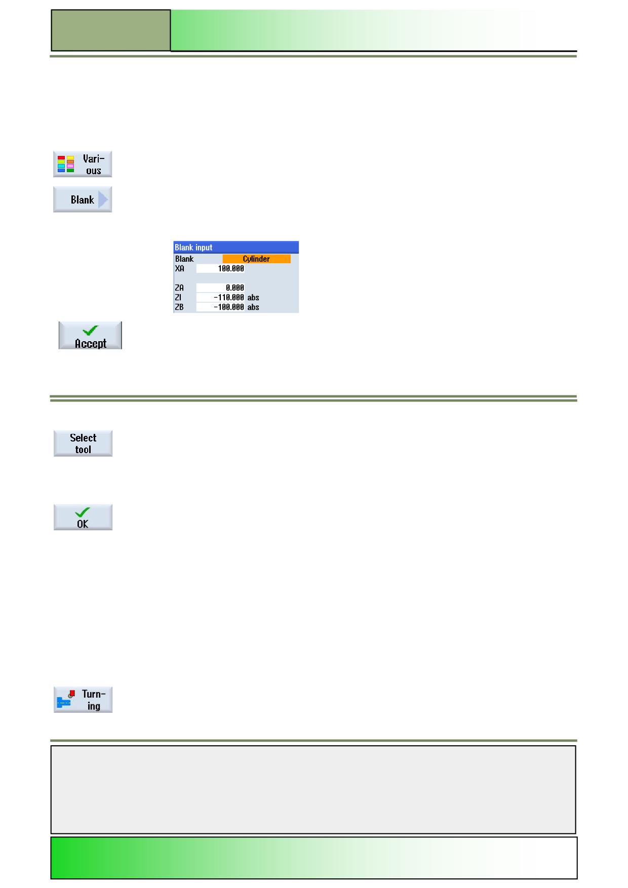
Insert now a blank for the simulation into the program.
Press the HSK 1.6 “Various” to open the work area “Various”.
Press the VSK 1 “Blank”.
The following input mask for the blank input opens.
3.
Insert following values/parameters for the blank:
Confirm your inputs by pressing the VSK 8 “Accept”.
The following line is inserted into the program:
N30 WORKPIECE(,,"","CYLINDER",192,0,-128,-90,100)
4.
Now, insert a new tool into the program.
Press the VSK 1.1 “Select tool“.
The tool list window opens.
Mark the desired tool “ROUGHING_A80” in the tool list window with the orange selection cur-
sor, by using the blue cursor keys on the keyboard.
Press the VSK 1.8 “OK”.
The following program line is inserted into the program:
N40 T="ROUGHING_80A"
Alternatively you can program the tool by hand.
5.
Insert the following G code commands into the program:
N50 S240 M4 F0.25
N60 LIMS=3000
6.
Insert a “Stock removal” cycle into the program.
(Stock removal1, Face)
Press the HSK 1.3 “Turning”, to open the technology “Turning”.
Notes
M634
Page 6
828D/840Dsl SINUMERIK Operate
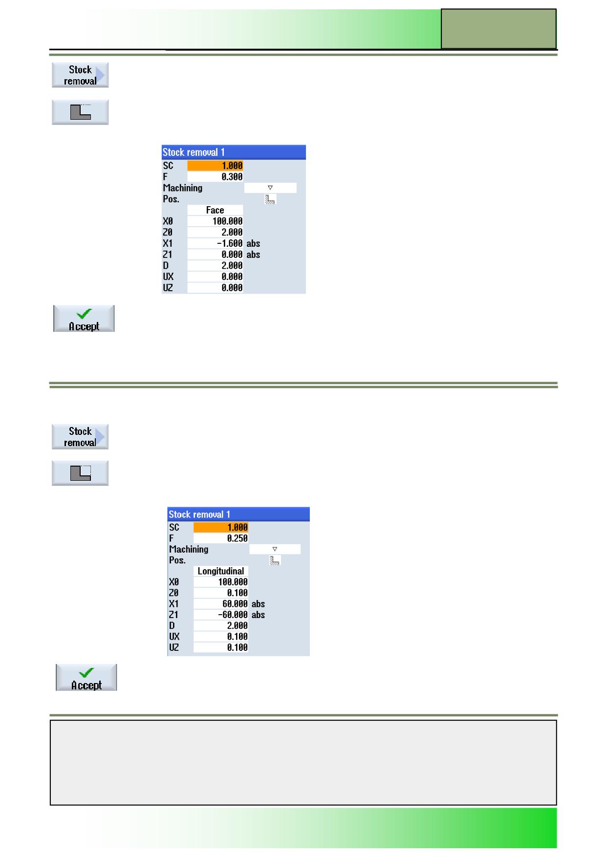
Turning with programGUIDE
M634
Press the VSK 1 “Stock removal”.
The work area with the functions for the technology “Stock removal” opens.
Press the VSK 3 “Stock removal 1”, to open the input mask for the “Stock removal 1” cycle.
7.
Fill out the input mask as displayed below:
Confirm your inputs by pressing the VSK 8 “Accept”.
The following line is inserted into the program:
N70 CYCLE951(100,2,-1.6,0,-1.6,0,1,2,0,0, 12,0,0,0,1,0.25,0,2,1110000)
8.
Insert a “Stock removal” cycle into the program.
(Stock removal1)
Press the VSK 1 “Stock removal”.
The work area with the functions for the technology “Stock removal” opens.
Press the VSK 3 “Stock removal 1”, to open the input mask for the “Stock removal 1” cycle.
9.
Fill out the input mask as displayed below:
Confirm your inputs by pressing the VSK 8 “Accept”.
The following line is inserted into the program:
N80 CYCLE951(100,0.1,60.-60,60,-60,1,2,0.1,0.1,11,0,0,0,1,0.25,0,2,1110000)
Notes
828D/840Dsl SINUMERIK Operate
Page 7
M634
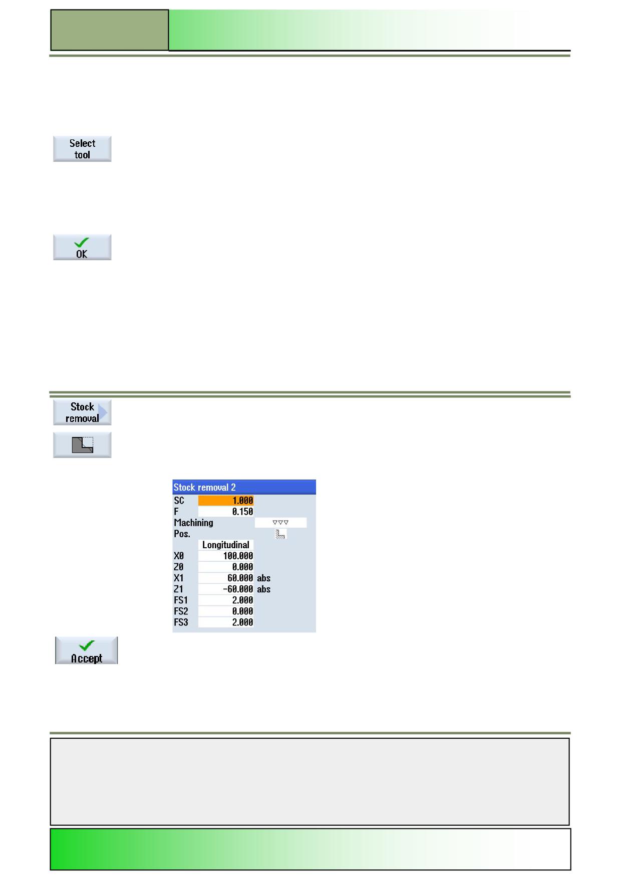
M634
Turning with programGUIDE
10.
Insert the following G code commands into the program:
N90 G0 X200 Z200
11.
Now, insert a new tool into the program.
(FINISHING_35A
Now, insert a new tool into the program.
Press the VSK 1.1 “Select tool“.
The tool list window opens.
Mark the desired tool “FINISHING_35A” in the tool list window with the orange selection cursor,
by using the blue cursor keys on the keyboard.
Press the VSK 1.8 “OK”.
The following program line is inserted into the program:
N100 T="FINISHING_35A"
Alternatively you can program the tool by hand.
12.
Insert the following G code commands into the program:
N110 S250 M4 F0.15
13.
Insert a “Stock removal” cycle into the program.
(Stock removal2, longitudinal)
Press the VSK 1 “Stock removal”.
The work area with the functions for the technology “Stock removal” opens.
Press the VSK 3 “Stock removal 2”, to open the input mask for the “Stock removal 2” cycle.
14.
Fill out the input mask as displayed below:
Confirm your inputs by pressing the VSK 8 “Accept”.
The following line is inserted into the program:
N120 CYCLE951(100,0,60,-60,60,-60,1,1,0.1,0.1, 21,2,0,2,1,0.15,1,2,1010000)
15.
Insert the following G code commands into the program:
N130 G00 X200 Z200
N140 M30
Notes
M634
Page 8
828D/840Dsl SINUMERIK Operate
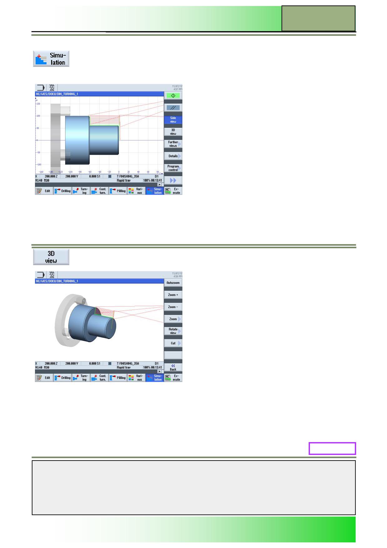
Turning with programGUIDE
M634
16.
Simulate the machining.
In order to start the simulation run, press the HSK 1.7 “Simulation”.
The control calculates the simulation parameters and opens the simulation in the simulation
window in a “Side view” by default.
To view the simulation with a view on the face of the blank, press the VSK 1.4 “3D view”.
M634: END
Notes
828D/840Dsl SINUMERIK Operate
Page 9
M634