SINUMERIK 840D sl. Training. Operate - Turning (2016-2020) - page 24
M611
Drilling with programGUIDE
Sinumerik
Operate
Module Description:
This module explains the programming of a simple drilling example with the programGUIDE in Shop-
Turn, by means of drilling cycles and position patterns.
Module Objective:
Working through this module you become familiar with the technology “Drilling” by pro-
gramming a G code program with programGUIDE in ShopTurn.
Content:
Simple programming example
This document was produced for training purposes.
828D/840Dsl SINUMERIK Operate v4.7
Page 1
M611
Siemens assumes no responsibility for its contents.
Drilling with programGUIDE
M611
Drilling
programGUIDE:
START
Simple
programming
example
Drilling
programGUIDE:
END
Notes
828D/840Dsl SINUMERIK Operate
Page 3
M611
M611
Drilling with programGUIDE
Simple programming example
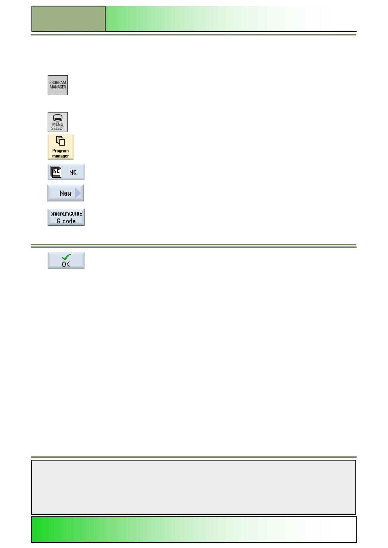
Creating a new programGUIDE program
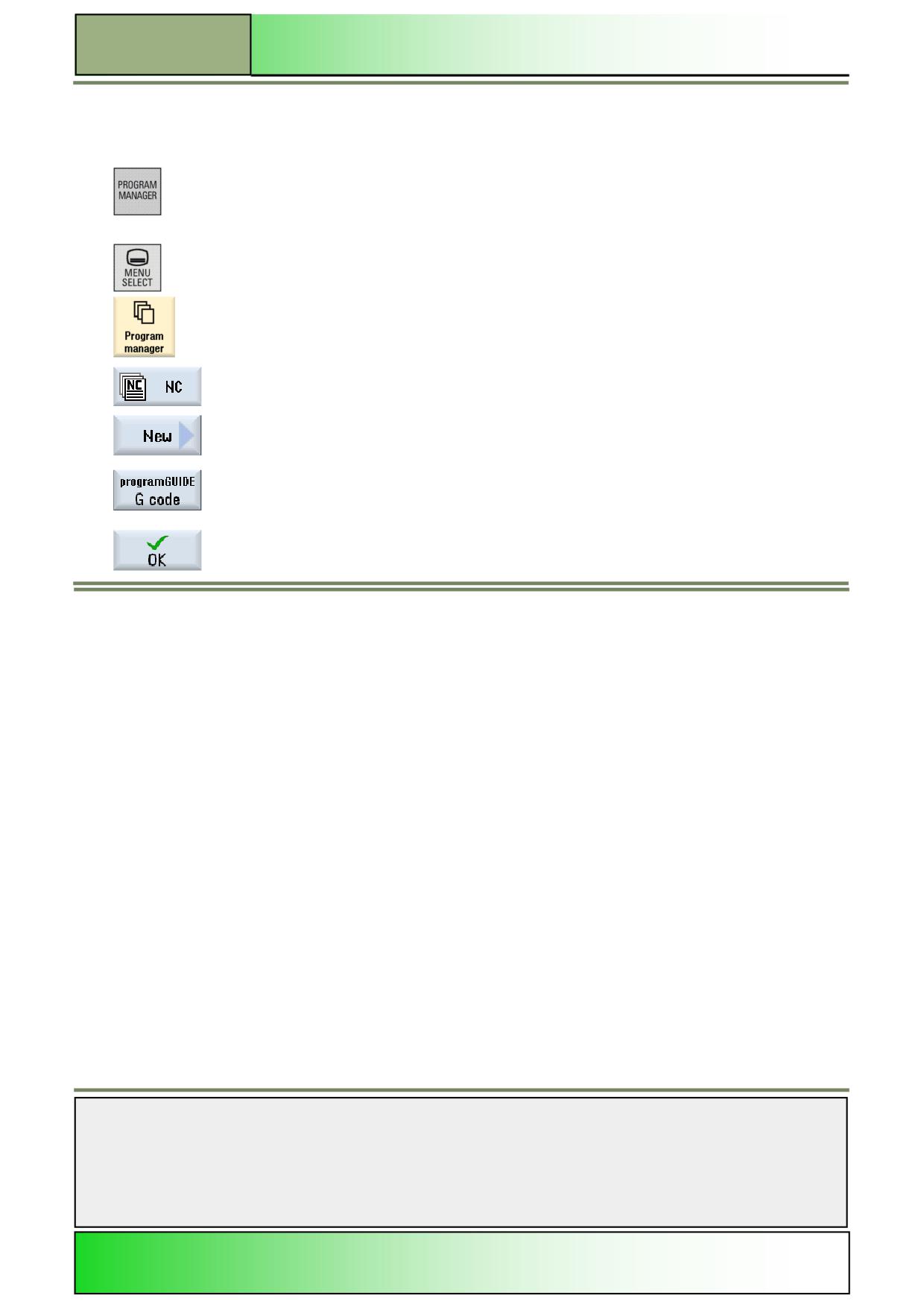
A new G code program can be created from within the operating modes “JOG, “MDA” and “AUTO” as follows:
1.
Press the “Program Manager”-key on the keyboard.
The program manager will be opened directly.
- OR -
1.
Press the “MENU SELECT”-key on the operator panel.
Press the yellow HSK 1.4 “Program Manager”.
The program manager window opens.
2.
Select a drive where you want to create the program (“NC”, “Local drive”, “USB”), by pressing a
horizontal softkey.
3.
Press the VSK 2 “New“.
The vertical softkey bar with functions for creating new programs opens.
4.
Press the VSK 4 „programGUIDE G code“ to open the input mask for creating a new G code
program.
Select “Main program MPF”.
5.
Assign a name for the program and confirm by pressing VSK 8 “OK”.
The control loads the program to the “Editor” operating area and opens the input screen for the
program
The editor window for entering G code commands opens.
Description:
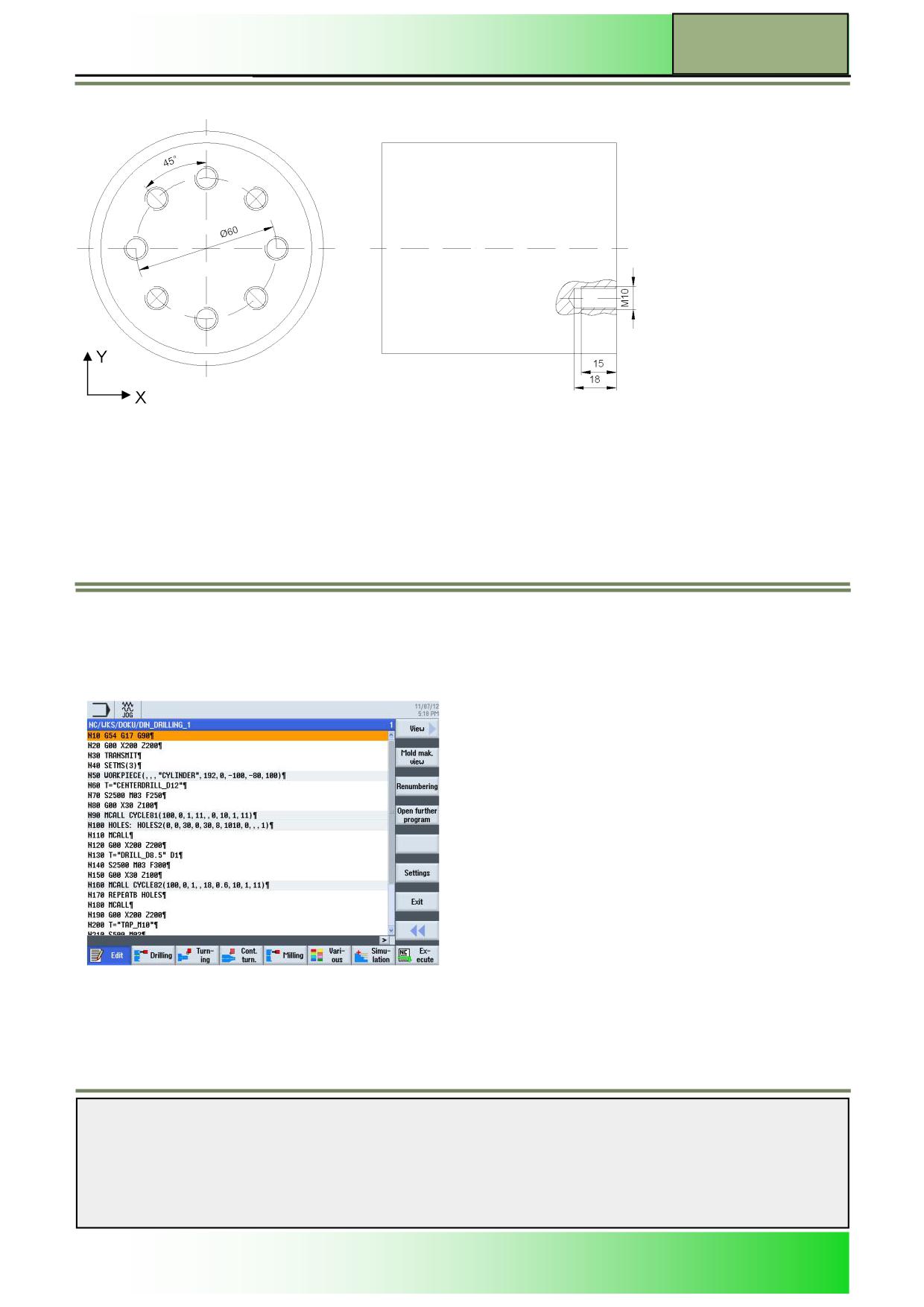
By using different drilling cycles (Centering, Drilling, Thread drilling) and a position pattern, a simple programGUIDE-
program (drill pattern) is to be created in ShopTurn.
Objective:
The workpiece shown below is to be programmed.
Afterwards, the program is to be simulated.
The following tools and technology data are to be used for programming.
Tool data:
Centre drill 12 mm (CENTERDRILL_D12)
Drill Ø 8,5 mm (DRILL_D8.5)
Tap M10 (TAP_M10)
Technology data:
F 150 mm/min
S 500 rpm
Approach strategy
As a start position for the machining, the first programmed drill hole is to be used.
This position is approached in rapid traverse.
Notes
M611
Page 4
828D/840Dsl SINUMERIK Operate
Drilling with programGUIDE
M611
Example: Drill pattern
The following program, with the call up of a drilling-, center drilling- and thread drilling-cycle, is to be programmed:
Create a new G code programGUIDE-program in ShopTurn, like described in section 2.1 in this module.
Give the program a name, for example “DIN_DRILLING_1”.
Notes
828D/840Dsl SINUMERIK Operate
Page 5
M611
M611
Drilling with programGUIDE
1.
Program the first G code lines of the program:
N10 G54 G17 G90 G0
N20 G0 X200 z200
N30 TRANSMIT
N40 SETMS(3)
2.
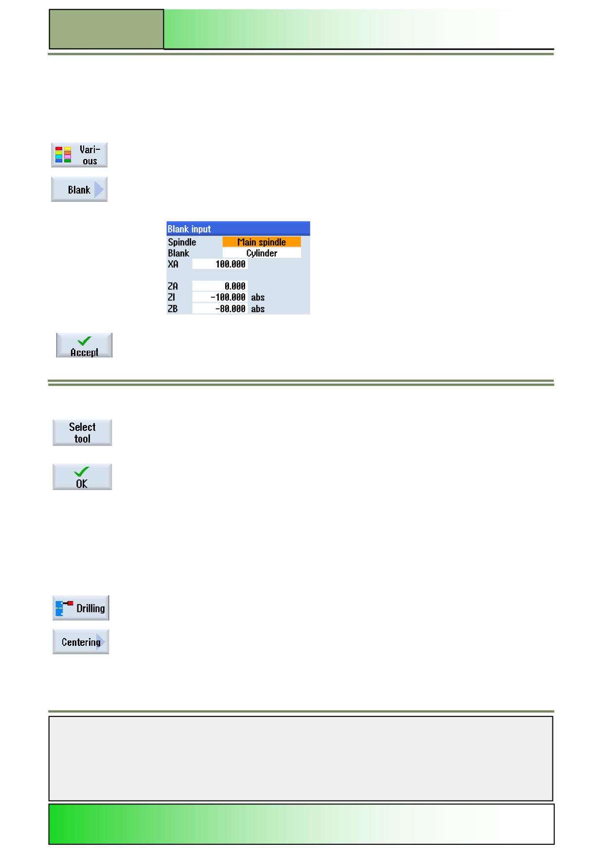
Now insert a blank for the simulation.
For this, press the HSK 1.6 “Various” to open the operating area “Various”.
Press the VSK 1 “Blank” to open the parameter mask for the blank.
3.
Fill in the following parameters for the blank:
Confirm your inputs by pressing the VSK 8 “Accept”.
The following line will be inserted into the program:
N40 WORKPIECE(,,"","CYLINDER",192,0,-100,
-80,100)
4.
Insert now a centre drill tool into the program.
Press the VSK 1.1 “Select tool”.
The tool list window opens.
Use the blue cursor keys to select the tool “CENTERDRILL_D12”.
Press the VSK 1.8 “OK”.
The program line N50 T="CENTERDRILL_D12" is inserted into the program.
Optional you can program the line by hand.
5.
Program the following G code commands:
N70 S2500 M3 F250
N80 G00 X30 Z100
6.
Program the centre drill cycle “CYCLE81”.
Press the HSK 1.2 “Drill.”, to open the technology “Drilling”.
Press the VSK 1 “Centering”.
The input mask for the centering cycle “CYCLE81” opens.
Notes
M611
Page 6
828D/840Dsl SINUMERIK Operate
Drilling with programGUIDE
M611
7.
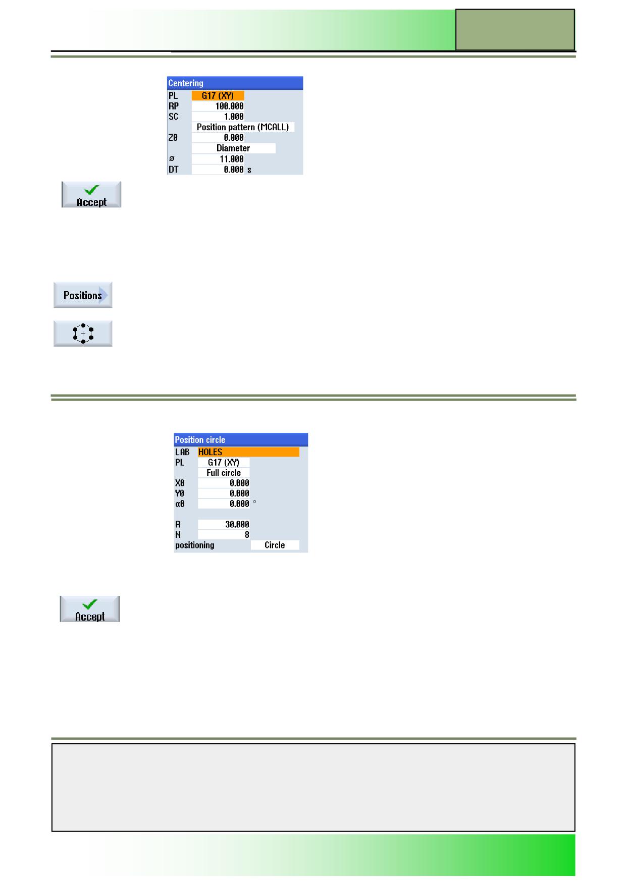
Fill out the input mask like displayed below:
Confirm your inputs by pressing the VSK 8 “Accept”.
The following line will be inserted into the program:
N90 MCALL CYCLE81(100,0,1,11,,0,10,1,11)
8.
Program now a position pattern (Position circle) for the following drillings.
Press the VSK 7 “Positions” for selecting a position pattern.
Press the VSK 5 “Position circle”. The parameter input mask for the position data of the bolt
hole pattern opens.
9.
Insert “HOLES” into the “LAB” field to set a name for the jump mark for the repeat positions.
Fill out the rest of the input mask like displayed below.
Confirm your inputs by pressing the VSK 8 “Accept”.
The following line will be inserted into the program:
N100 HOLES: HOLES (0,0,30,0,30,8,1010, 0,,,1).
10.
Program the following G code commands:
N110 MCALL
N120 G00 X200 Z200
11.
Insert the following tool “DRILL_D8.5” into the program (see step 5) or program the following
line by hand:
N130 T="Drill_D8.5" D1
Notes
828D/840Dsl SINUMERIK Operate
Page 7
M611
M611
Drilling with programGUIDE
12.
Program the following G code commands:
N140 S2500 M3 F300
N150 G00 X30 Z100
13.
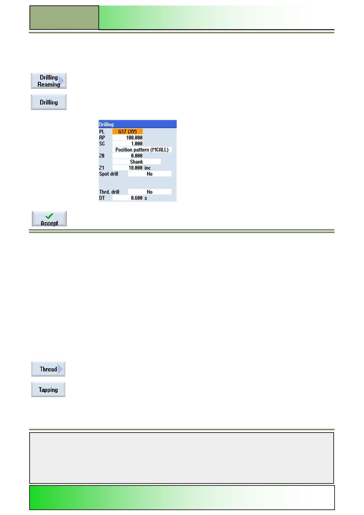
Program the cycle for the drilling (CYCLE82).
Press the VSK 2 “Drilling Reaming”.
Press the VSK 3 “Drilling”.
The input mask for the drilling cycle “CYCLE82” opens.
14.
Fill out the input mask like displayed below:
Accept your inputs by pressing the VSK 8 “Accept”.
The following line will be inserted into the program:
N160 MCALL CYCLE82(100,0,1,,18,0.6,10,1,11).
15.
Enter the following G code lines:
N170 REPEATB HOLES
N180 MCALL
N190 G00 X200 Z200
16.
Insert the tool “TAP_M10” into the program (see step 5) or program the following line by hand:
N200 T="TAP_M10"
17.
Program the following G code commands:
N210 S500 M3
N220 G00 X30 Z100
18.
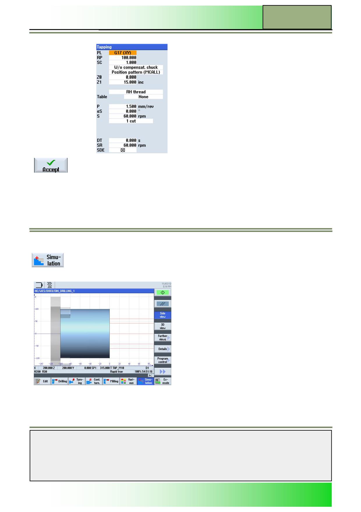
Finally program the cycle for the thread drilling
(CYCLE84).
Press the VSK 5 “Thread”.
If not active by default, press the VSK 3 “Tapping” to open the input mask for the CYCLE84
“Tapping”.
Notes
M611
Page 8
828D/840Dsl SINUMERIK Operate
Drilling with programGUIDE
M611
19.
Fill out the input mask like displayed below:
Accept your inputs by pressing the VSK 8 “Accept”.
The following line will be inserted into the program:
N230 MCALL CYCLE84(100,0,1,,15,0,5,,1.5,0,
60,60,0,1,0,0,5,1.4,,,,,1001,2001001)
20.
Enter following G code lines and end the program:
N240 REPEATB HOLES
N250 MCALL
N260 TRAFOOF
N270 G0 X200 Z200
N280 M30
21.
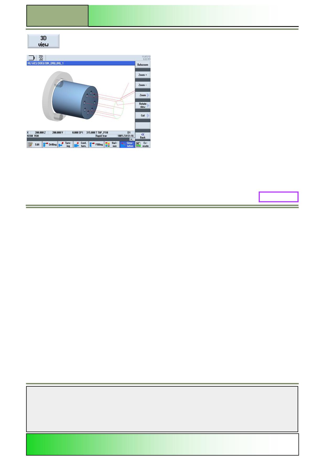
Start the simulation of the program.
Press the HSK 1.7 “Simulation” to open the simulation window. The control calculates the
simulation and shows the simulation in a side view.
Notes
828D/840Dsl SINUMERIK Operate
Page 9
M611
M611
Drilling with programGUIDE
To see the simulation of the machining from the front of the blank, press the VSK 1.4 “3D
view”.
M611: END
Notes
M611
Page 10
828D/840Dsl SINUMERIK Operate
M626
Contour turning with programGUIDE
Sinumerik
Operate
Module Description:
This module explains the programming of a contour turning machining with the programGUIDE in
ShopTurn, by means of contour descriptions, stock removal and grooving cycles.
Module Objective:
Working through this module you become familiar with the technology „Contour turning“
by programming a G code program with the programGUIDE in ShopTurn.
Content:
Simple programming example
This document was produced for training purposes.
828D/840Dsl SINUMERIK Operate v4.7
Page 1
M626
Siemens assumes no responsibility for its contents.
M626
M626
Page 2
828D/840Dsl SINUMERIK Operate
Contour turning with programGUIDE
M626
Contour turning
programGUIDE:
START
Simple
programming
example
Contour turning
programGUIDE:
END
Notes
828D/840Dsl SINUMERIK Operate
Page 3
M626
M626
Contour turning with programGUIDE
Simple programming example
Creating a new programGUIDE program
A new G code program can be created from within the operating modes “JOG, “MDA” and “AUTO” as follows:
1.
Press the “Program Manager”-key on the keyboard.
The program manager will be opened directly.
- OR -
1.
Press the “MENU SELECT”-key on the operator panel.
Press the yellow HSK 1.4 “Program Manager”.
The program manager window opens.
2.
Select a drive where you want to create the program (“NC”, “Local drive”, “USB”), by pressing a
horizontal softkey.
3.
Press the VSK 2 “New“.
The vertical softkey bar with functions for creating new programs opens.
4.
Press the VSK 4 „programGUIDE G code“ to open the input mask for creating a new G code
program.
Select “Main program MPF”.
5.
Assign a name for the program and confirm by pressing VSK 8 “OK”.
The control loads the program to the “Editor” operating area and opens the input screen for the
program
The editor window for entering G code commands opens.
Description:
A complex ShopTurn sequential program (SHAFT) is to be programmed, by using different turning cycles (contour, stock
removal, groove cutting).
Objective:
The workpiece shown below is to be programmed.
Then the program is to be simulated.
The following tool and technology data are to be used for programming:
Tool and
ROUGHING_80A
technology data:
(F 0,3 mm/min, V 260 m/min)
FINISHING_35A
(F 0,15 mm/min V 270 m/min)
GROOVE_3A
(F 0,08 mm/min, 2000 rpm)
Approach strategy:
The following position is programmed as the
contour starting point:
X
12
Z
0
This point will be approached in the cycle automatically with rapid traverse.
Notes
M626
Page 4
828D/840Dsl SINUMERIK Operate
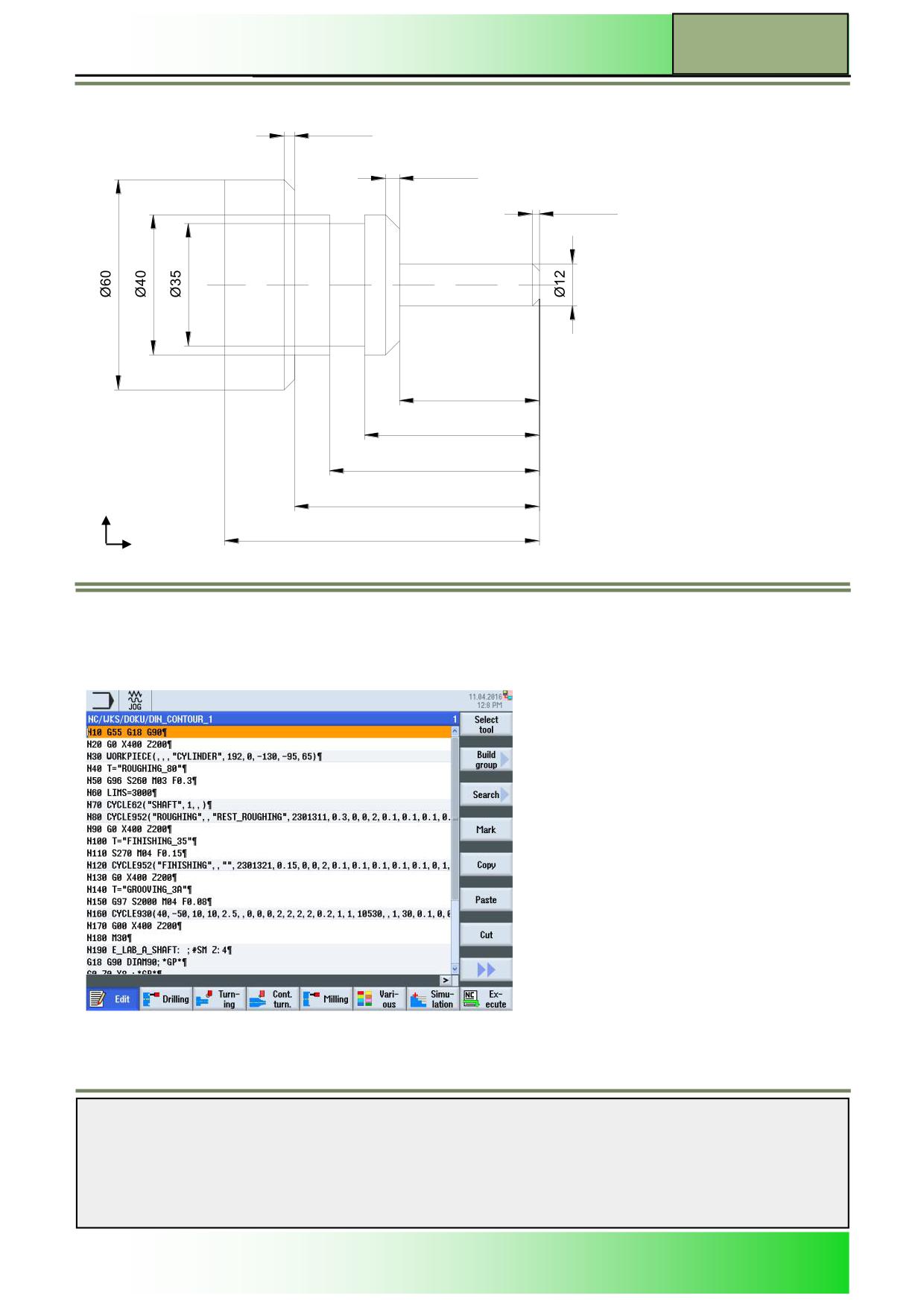
Contour turning with programGUIDE
M626
3x45°
4x45°
2x45°
40
50
60
70
X
90
Z
Programming example: Spigot
The following program is to be created, with the call up of contour descriptions, as well as stock removal and residual cut-
ting cycles.
Notes
828D/840Dsl SINUMERIK Operate
Page 5
M626
M626
Contour turning with programGUIDE
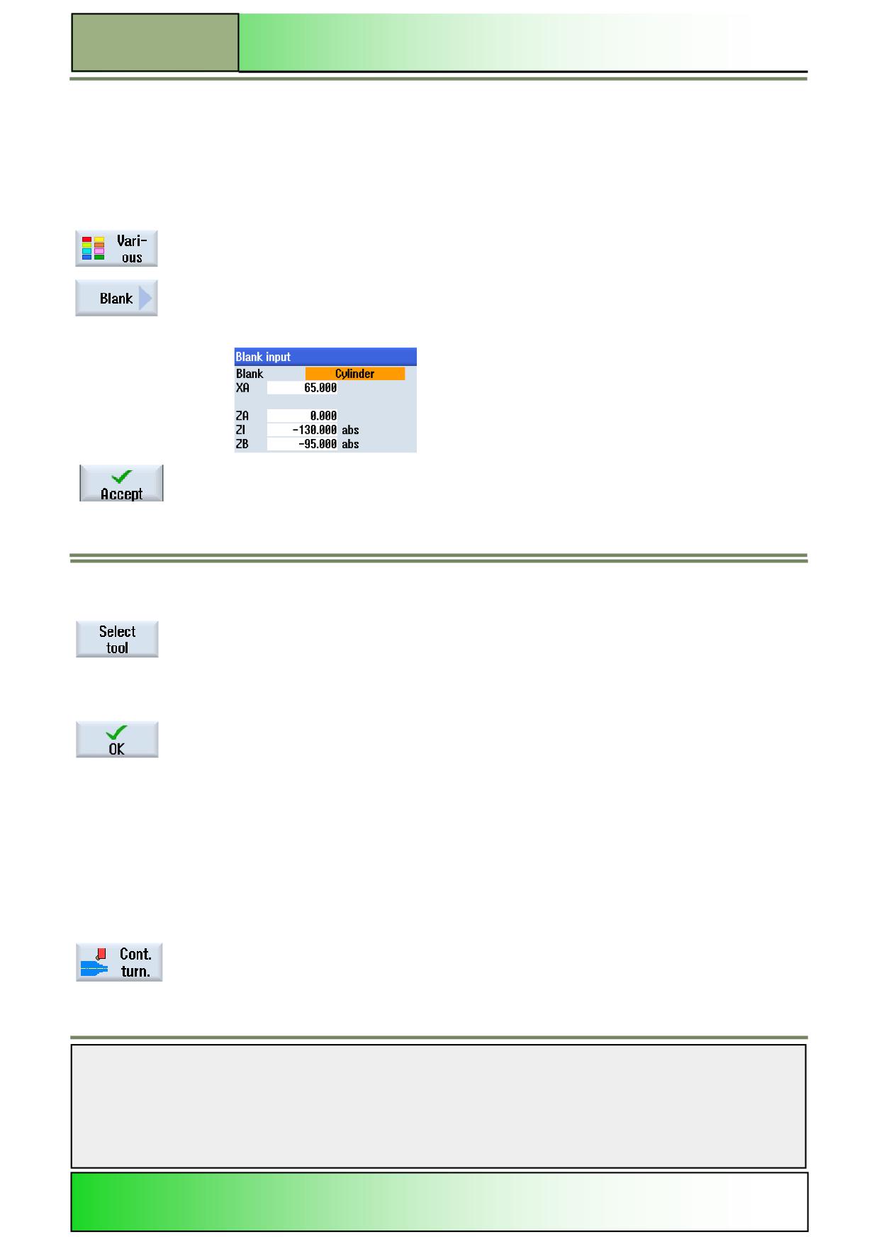
Create a new G code programGUIDE-program in ShopTurn, and give the program a name, for example
„DIN_CONTOUR_1.MPF“.
1.
Program now the first lines of the program with following G code commands:
N10 G55 G18 G90 G00
N20 G00 X200 Z200
2.
Insert a blank for the simulation into the program.
Press the HSK 1.6 “Various” to open the working area “Various”.
Here, press the VSK 1 “Blank” to open the parameter window for the blank.
3.
Enter the following parameters for the blank:
Confirm your inputs by pressing the VSK 8 “Accept”.
The following program line will be inserted into the program:
N30 WORKPIECE(,,"","CYLINDER",192,0,-130,
-95,65)
4.
Insert now a tool into the program.
Press the VSK 1.1 “Select tool“.
The tool list window opens.
Select the tool “ROUGHING_80A” by using the blue cursor key on the keyboard.
Press the VSK 1.8 “OK”.
Following program line is inserted into the program:
N40 T="ROUGHING_80A"
5.
Program the following G code commands.
N50 G96 S260 M04 F0.3
N60 LIMS=3000
6.
Program now the call up of the contour “CYCLE62”.
Note:
The contour itself is programmed at the end of the program.
For this, press the HSK 1.4 “Cont. turn.” to open the technology “Contour turning”.
Notes
M626
Page 6
828D/840Dsl SINUMERIK Operate
Contour turning with programGUIDE
M626
Press now the VSK 1 “Contour”.
The vertical softkey bar with functions for creating or calling up a contour opens.
Press the VSK 2 “Contour call” to open the input mask for the contour call up.
7.
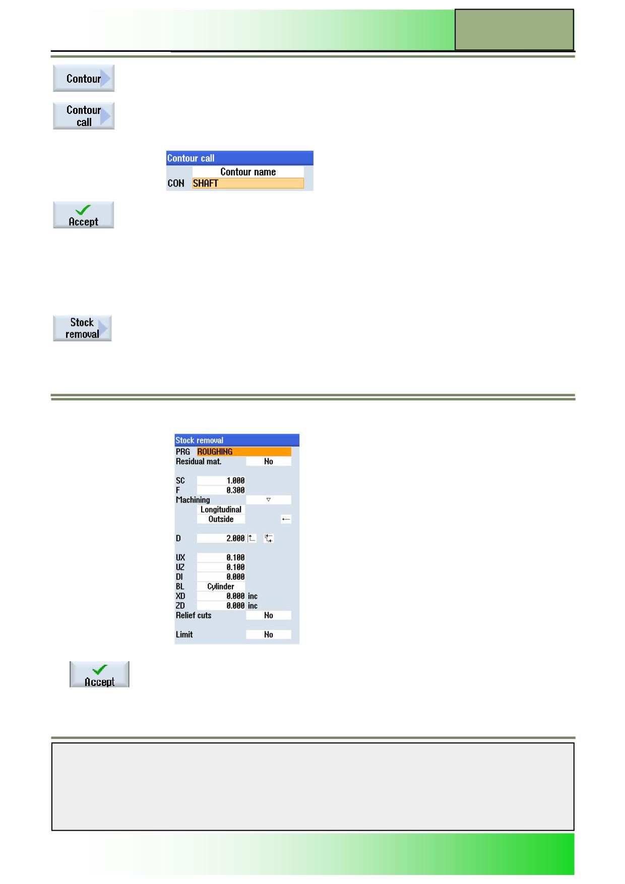
Insert the following contour name into the input mask:
Confirm your input by pressing the VSK 8 “Accept”.
The following line is inserted into the program:
N70 CYCLE62("SHAFT",1,,)
Note:
The contour “SHAFT” you called up here, will be created in section 2.
8.
Program now the next contour call “CYCLE952”.
Press now the VSK 2 “Stock removal”.
The vertical softkey bar with function for creating or calling up a contour opens.
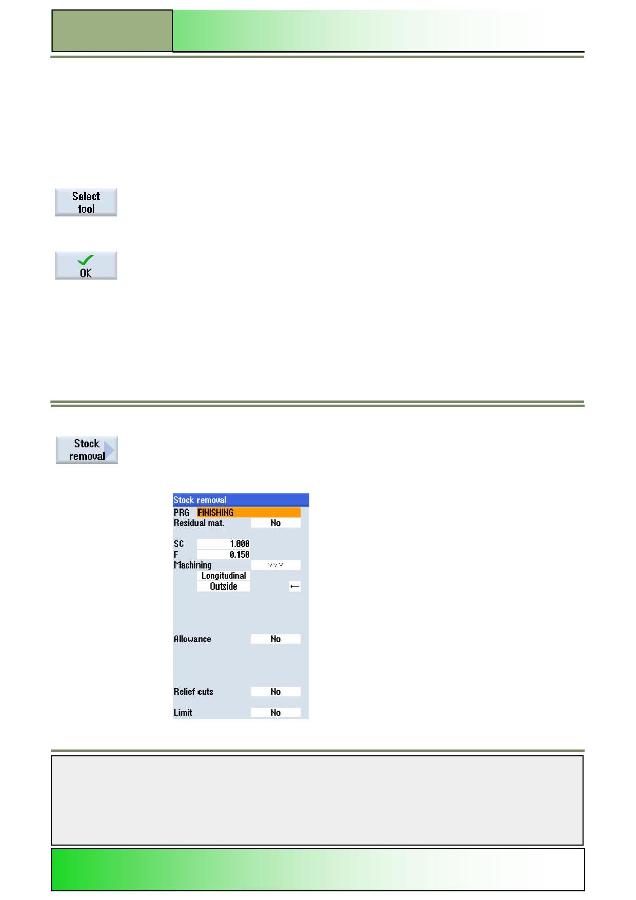
Fill out the input mask as follows:
11.
Confirm your inputs by pressing the VSK 8 “Accept”.
Notes
828D/840Dsl SINUMERIK Operate
Page 7
M626
M626
Contour turning with programGUIDE
11.
The following program code is inserted into the program:
N80 CYCLE952("ROUGHING",,"",2101311,0.3,0,
0,2,0.1,0.1,0.1,0.1,0.1,65,0,,,,,2,2,,,0,1,,0,12,10,1,0)
12.
Program this line with the following G-code commands:
N90 G0 X200 Z200
13.
Insert another tool into the program.
Press the VSK 1.1 “Select tool“.
The tool list window opens.
Select the tool “FINISHING_35A” by using the blue cursor key on the keyboard.
Press the VSK 1.8 “OK”.
The following program line is inserted into the program:
N100 T="FINISHING_35A"
Optionally you can program the tool by hand.
14.
Program this line with the following G-code commands:
N110 S270 M04 F0.15
15.
Insert a contour call “CYCLE952” into the program.
Press the VSK 2 "removal" to the input screen for the technology "removal" to open.
16.
Fill in the input mask as follows:
Notes
M626
Page 8
828D/840Dsl SINUMERIK Operate
Contour turning with programGUIDE
M626
17.
Confirm your inputs by pressing the VSK 8 “Accept”.
18.
The following program code is inserted into the program:
N120 CYCLE952("FINISHING",,"",2101321,0,
15,0,0,2,0.1,0.1,0.1,0.1,0.1,65,0,,,,,2,2,,,0,1,,0,12,10,1,0)
19.
Program the following G code commands:
N130 G0 X200 Z200
20.
Now add a tool into the program.
Press the VSK 1.1 “Select tool“.
The tool list window opens.
Select the tool “GROOVE_3A” by using the blue cursor key on the keyboard.
Press the VSK 1.8 “OK”.
21.
Program the following G code command:
N150 G97 S2000 M04 F0.08
22.
Now add a recess cycle "CYCLE930" into the program.
23.
Press the HSK 1.3 "Turning".
Press the VSK 2 "groove" to open the input screen for the technology "Recess".
Select “GROOVE 1”
24.
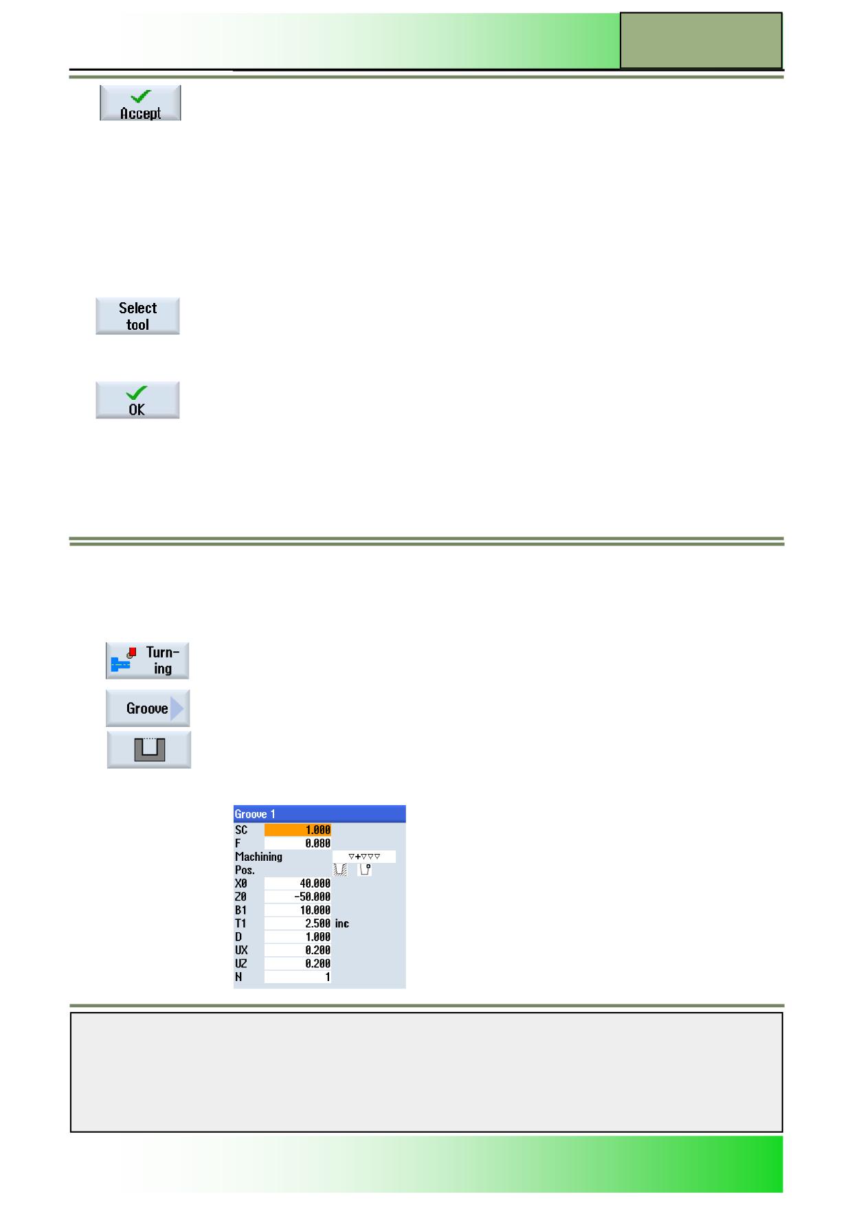
Fill out the input mask as follows:
Notes
828D/840Dsl SINUMERIK Operate
Page 9
M626
M626
Contour turning with programGUIDE
25.
Confirm your inputs by pressing the VSK 8 “Accept”.
The following program code is inserted into the program:
N160 CYCLE930(40,-50,10,10,2.5,,0,0,0,2,2
,2,2,0,2,1,1,10530,,1,30,0.08,0,0.2,0.2,2,1111110)
Program the following G code commands:
N170 G00 X200 Z200
N180 M30
26.
Now add the contour description for the "PIN" in the program.
Press HSK 1.4 “Contour Turn“
Now press the VSK 1 "contour".
The vertical softkey to create and call a new contour is opened.
Press the VSK 1 "New contour" to create a new contour.
The input screen for the creating of a contour name opens.
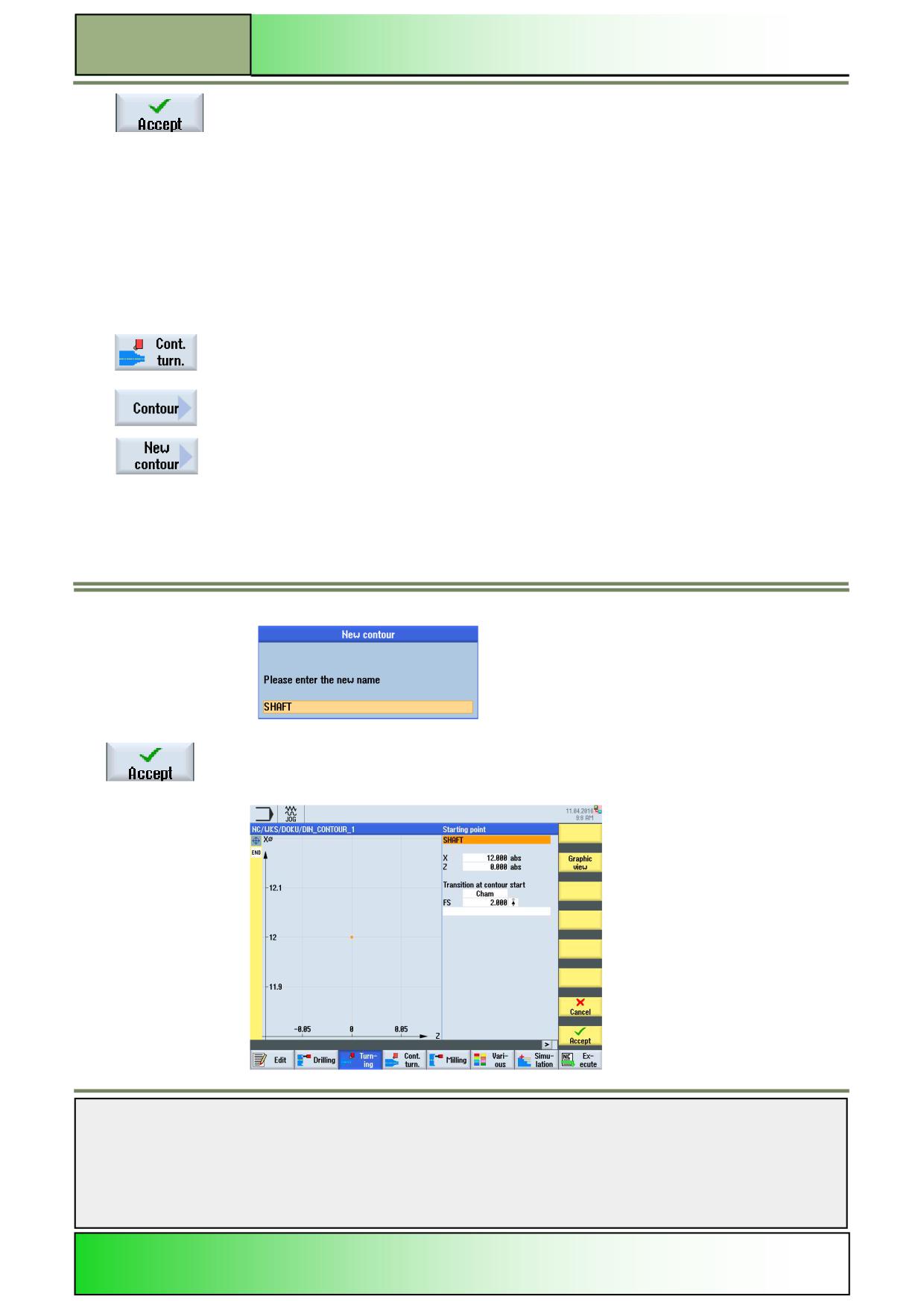
32.
Enter the following name for the new contour:
Confirm your input by pressing the VSK 8 “Accept”.
The contour editor with the input mask for the contour description opens automatically.
Enter the contour starting point:
Notes
M626
Page 10
828D/840Dsl SINUMERIK Operate
Contour turning with programGUIDE
M626
28.
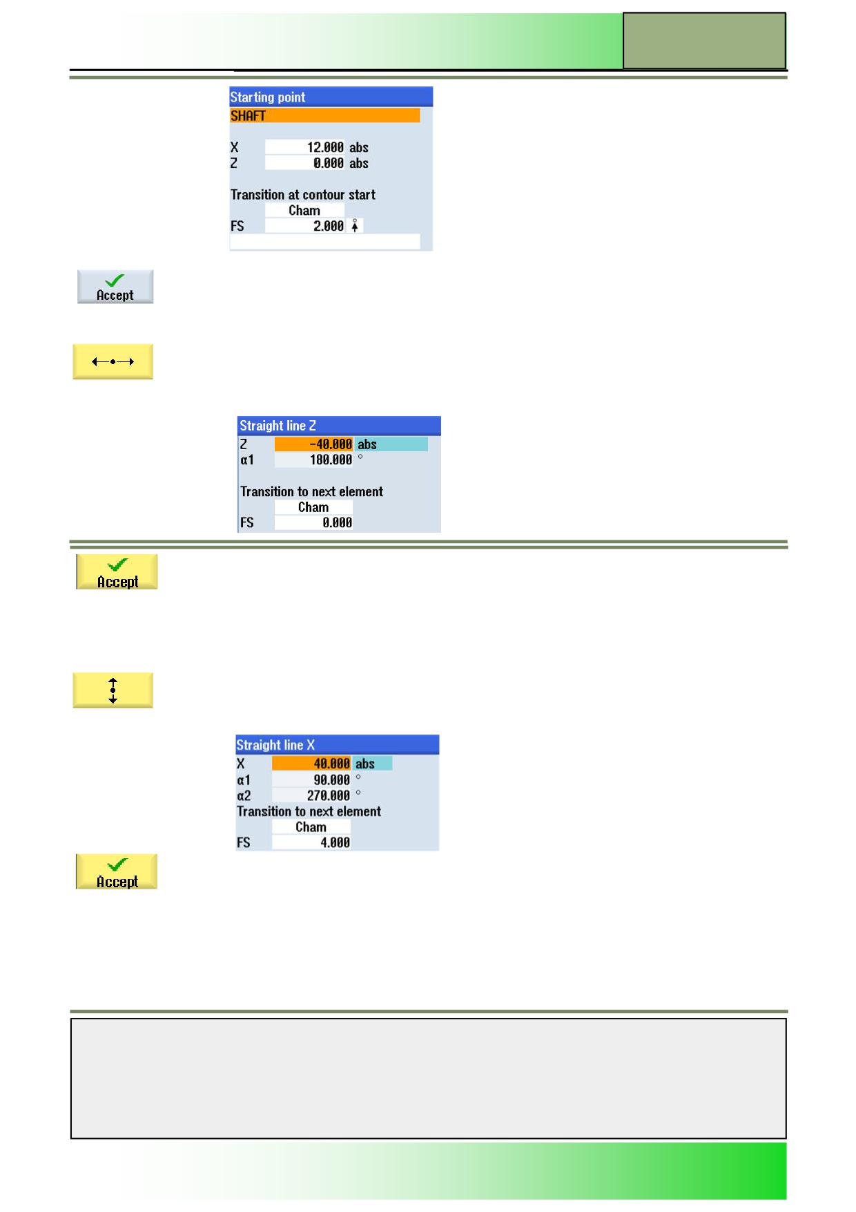
Enter the following coordinates as a starting point.
Confirm your input by pressing the VSK 8 “Accept”.
29.
Start the contour description with a straight line in direction “Z”.
Press the VSK 1.2 “Straight line Z”.
The parameter window for the “Straight line Z” opens.
30.
Insert the following coordinates into the input mask:
Confirm your inputs by pressing the VSK 8 “Accept”.
Note:
By entering the value for “Z, the starting value to the Z-axis “α1” is calculated automatically.
31.
Extend the contour description by adding a “Straight line X”.
Press the VSK 1.3 “Straight line X”.
The parameter window for the “Straight line Z” opens.
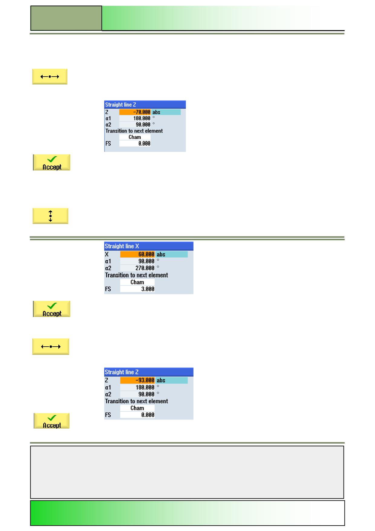
32.
the input mask:
Confirm your inputs by pressing the VSK 8 “Accept”.
Notes
828D/840Dsl SINUMERIK Operate
Page 11
M626
M626
Contour turning with programGUIDE
33.
Extend the contour description by adding a “Straight line Z”.
Press the VSK 1.2 “Straight line Z”.
The parameter window for a straight line in Z direction opens.
34.
Insert the following coordinates into the input mask:
Confirm your inputs by pressing the VSK 8 “Accept”.
Note:
By entering the value for “Z”, the values for “α1” and “α2” are calculated automatically.
35.
Extend the contour by adding a line in X direction.
Press the VSK 1.3 “Straight X”.
The parameter window for a straight line in ZX direction opens.
36.
Insert the following coordinates into the input mask:
Confirm your inputs by pressing the VSK 8 “Accept”.
Note:
By entering the values for “X” , the values for “α1” and “α2” are calculated automatically.
37.
Extend the contour by adding a line in Z direction.
Press the VSK 1.2 “Straight line Z”.
The parameter window for a straight line in Z direction opens.
38.
Insert the following coordinates into the input mask:
Confirm your inputs by pressing the VSK 8 “Accept”.
Notes
M626
Page 12
828D/840Dsl SINUMERIK Operate
Contour turning with programGUIDE
M626
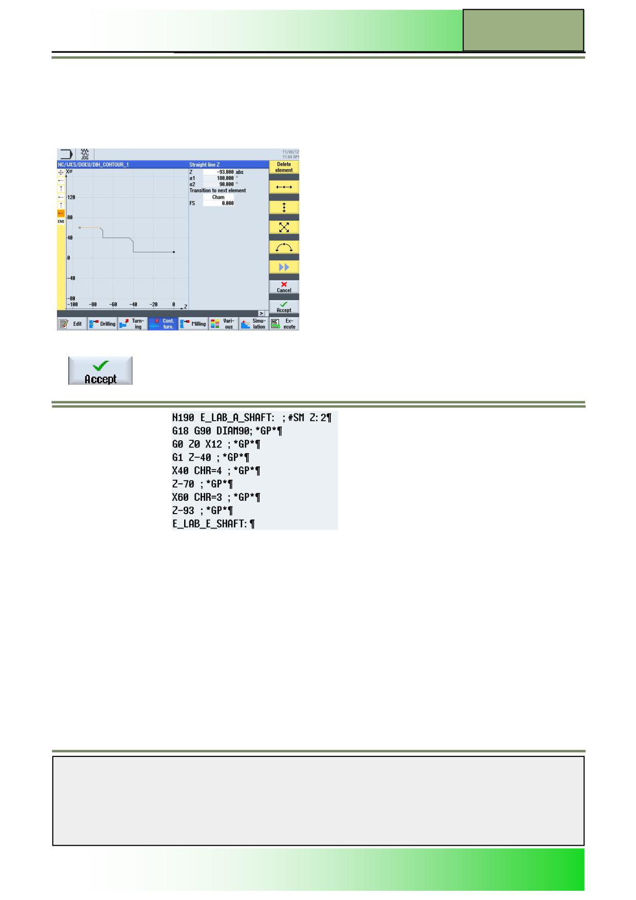
39.
Examine now the finished contour.
Press the blue “cursor-to-the-left” key on the keyboard, to switch with the orange selection cur-
sor to the yellow contour step bar on the left side of the screen (see picture below).
Use the blue “cursor-down” key on the keyboard to place the orange selection cursor on the
END-symbol.
The following screen with the a sketch of the finished
contour outline is displayed:
40.
Finish the creation of the contour by pressing the VSK 8 “Accept”
The following G code lines are inserted into the program:
Notes
828D/840Dsl SINUMERIK Operate
Page 13
M626
M626
Contour turning with programGUIDE
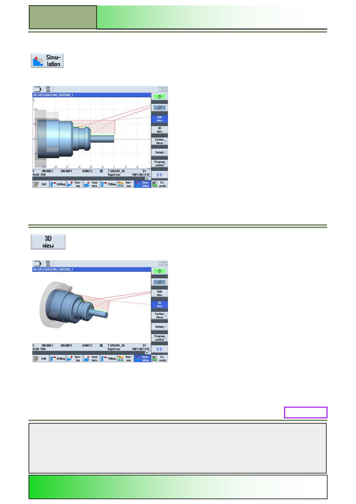
41.
Simulate the machining.
Press the HSK 1.7 “Simulation” to start the simulation of the program.
The control calculates the simulation parameters and the simulation window opens, showing the
workpiece in a side view, by default.
To view the simulation with a view on the face of the work piece, press the VSK 1.4 “3D view”.
M626: END
Notes
M626
Page 14
828D/840Dsl SINUMERIK Operate
M661
Contour Milling with programGUIDE
Sinumerik
Operate
Module Description:
This module explains the programming of a contour miling machining with the programGUIDE in
ShopTurn, by means of contour descriptions, and stock removal cycle.
Module Objective:
Working through this module you become familiar with the technology „Contour milling“
by programming a G code program with the programGUIDE in ShopTurn.
Content:
Simple program example
This document was produced for training purposes.
828D/840Dsl SINUMERIK Operate v4.7
Page 1
M661
Siemens assumes no responsibility for its contents.
M661
M661
Page 2
828D/840Dsl SINUMERIK Operate
Contour Milling with programGUIDE
M661
Contour Milling:
START
Simple
program
example
Contour Milling:
END
Notes
828D/840Dsl SINUMERIK Operate
Page 3
M661
M661
Contour Milling with programGUIDE
Simple program example
Creating a new programGUIDE program
A new G code program can be created from within the operating modes “JOG, “MDA” and “AUTO” as follows:
1.
Press the “Program Manager”-key on the keyboard.
The program manager will be opened directly.
- OR -
1.
Press the “MENU SELECT”-key on the operator panel.
Press the yellow HSK 1.4 “Program Manager”.
The program manager window opens.
2.
Select a drive where you want to create the program (“NC”, “Local drive”, “USB”), by pressing a
horizontal softkey.
3.
Press the VSK 2 “New“.
The vertical softkey bar with functions for creating new programs opens.
4.
Press the VSK 4 „programGUIDE G code“ to open the input mask for creating a new G code
program.
Select “Main program MPF”.
5.
Assign a name for the program and confirm by pressing VSK 8 “OK”.
The control loads the program to the “Editor” operating area and opens the input screen for the
program
The editor window for entering G code commands opens.
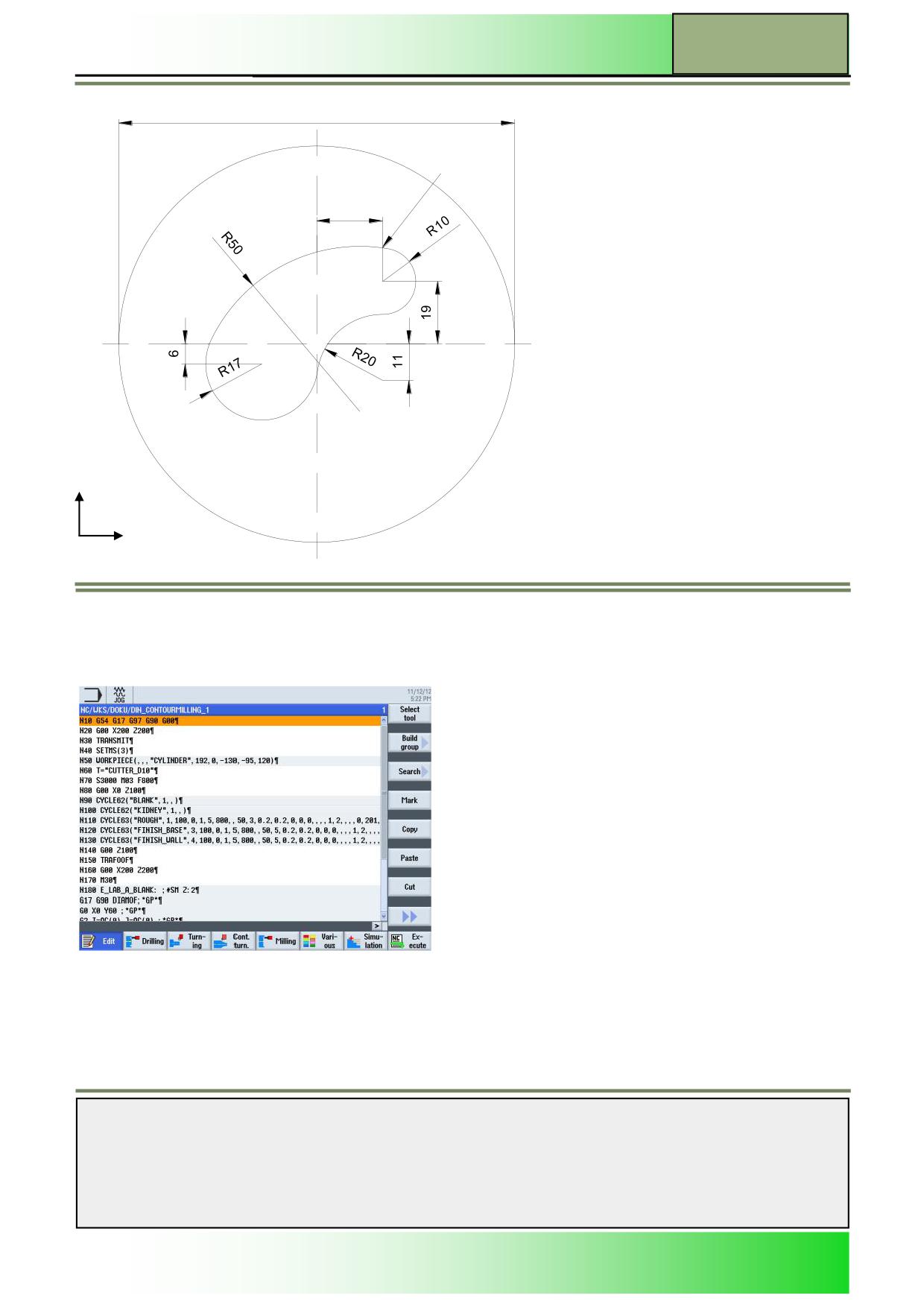
Description:
A G code program (Kidney) is to be programmed with programGUIDE with the aid of various milling cycles (spigot).
Objective:
The workpiece shown below is to be programmed.
The program is then to be simulated.
The following tool and technology are required for the programming:
Tool and
CUTTER_D10
technology data:
(F800 mm/min, S3000 rpm)
Contour starting point:
The following position is programmed as the contour starting point:
Contour 1:
X0 Y60 (blank)
Contour 2:
X20 Y29 (kidney)
Notes
M661
Page 4
828D/840Dsl SINUMERIK Operate
Contour Milling with programGUIDE
M661
Ø120
Startpunkt
20
t=5
Y
X
Program example: Kidney
The following program with call of two contour definitions as well as the spigot milling cycle is to be programmed.
Create a new G code program with programGUIDE as described in this module and name the program, for example,
“DIN_CONTOURMILLING_1.MPF”.
Notes
828D/840Dsl SINUMERIK Operate
Page 5
M661
M661
Contour Milling with programGUIDE
1.
Program the first lines of the program with the
following G code commands:
N10 G54 G17 G97 G90 G00
N20 G00 X200 Z200
N30 TRANSMIT
N40 SETMS(3)
2.
Insert a blank for the simulation.
To do this, press HSK 1.6 “Various” to call the “Various” working area.
Press VSK 1 “Blank” to open the input screen for the blank parameters.
3.
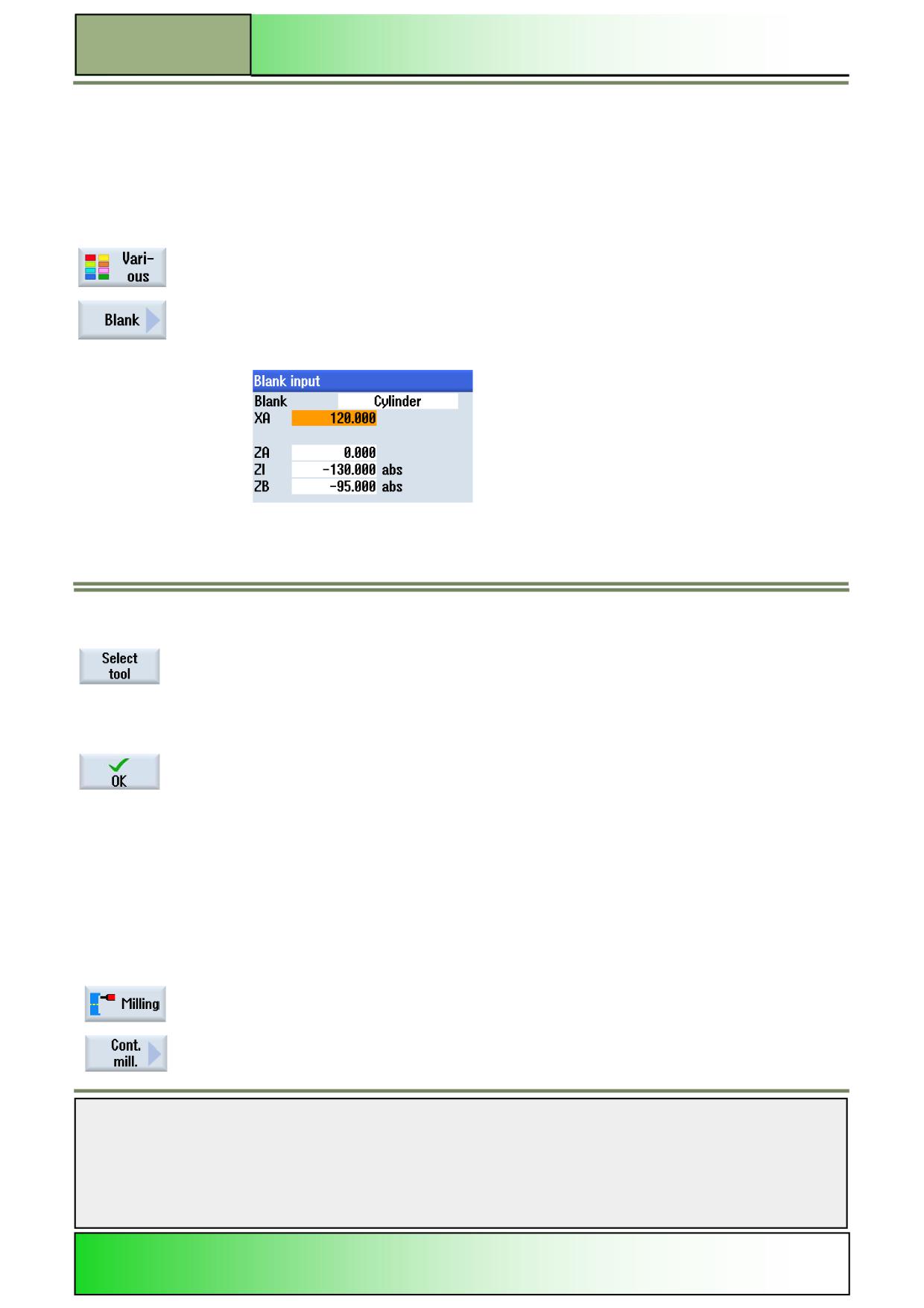
Enter the following parameters for the blank:
Confirm the entries with VSK 8 “Accept”.
The following line is inserted:
N50 WORKPIECE(, , ,"CYLINDER",192,0,-130, -95,120)
4.
Now insert a tool in the program.
Press VSK 1.1 “Select tool”.
The tool list opens.
With the blue cursor keys on the keyboard, select the “CUTTER_D10” tool.
Press VSK 1.8 “OK”.
The following line is inserted in the program:
N60 T="CUTTER_D10"
5.
Program the following G code commands:
N70 S3000 M3 F800
N80 G00 X0 Z100
6.
Program the first contour call “CYCLE62”.
Note:
(The actual contour definition is performed at the end of the program.)
To do this, press HSK 1.5 “Milling” to call the “Milling” function.
Now press VSK 8 “Cont. mill.” followed by VSK 1 “Contour”.
The vertical softkey bar to create and call a new
contour opens.
Notes
M661
Page 6
828D/840Dsl SINUMERIK Operate
Contour Milling with programGUIDE
M661
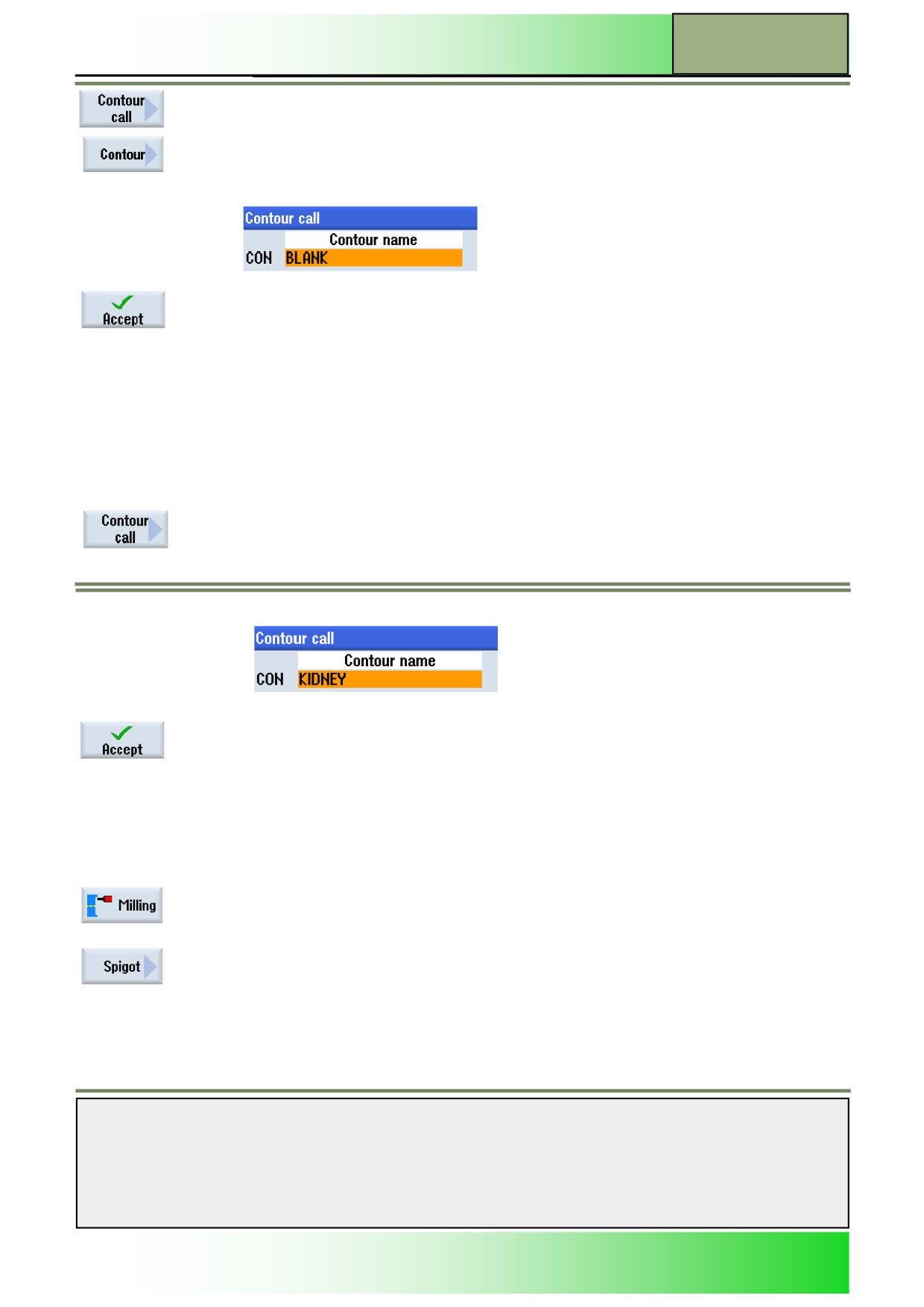
Press VSK 2 “Contour call” to open the input window for the contour call.
7.
Enter the following contour name in the input screen:
Confirm the entries with VSK 8 “Accept”.
The following line is inserted in the program:
N90 CYCLE62("BLANK",1, ,)
Note:
(The “BLANK” contour called here is not created
until later)
8.
Now insert a further “CYCLE62” contour call in the program.
Press VSK 2 “Contour call” to open the input
window for the contour call.
9.
Enter the following contour name in the input screen:
Confirm the entries with VSK 8 “Accept”.
The following line is inserted in the program:
N100 CYCLE62("KIDNEY",1, ,)
Note:
(The “KIDNEY” contour called here is not created
10.
until later in this section)
Now press HSK 1.5 “Milling” followed by VSK 8 “Cont. mill.” to call the “Milling” function.
Now press VSK 6 “Spigot”.
The input screen for the “Spigot” milling cycle opens.
Notes
828D/840Dsl SINUMERIK Operate
Page 7
M661
M661
Contour Milling with programGUIDE
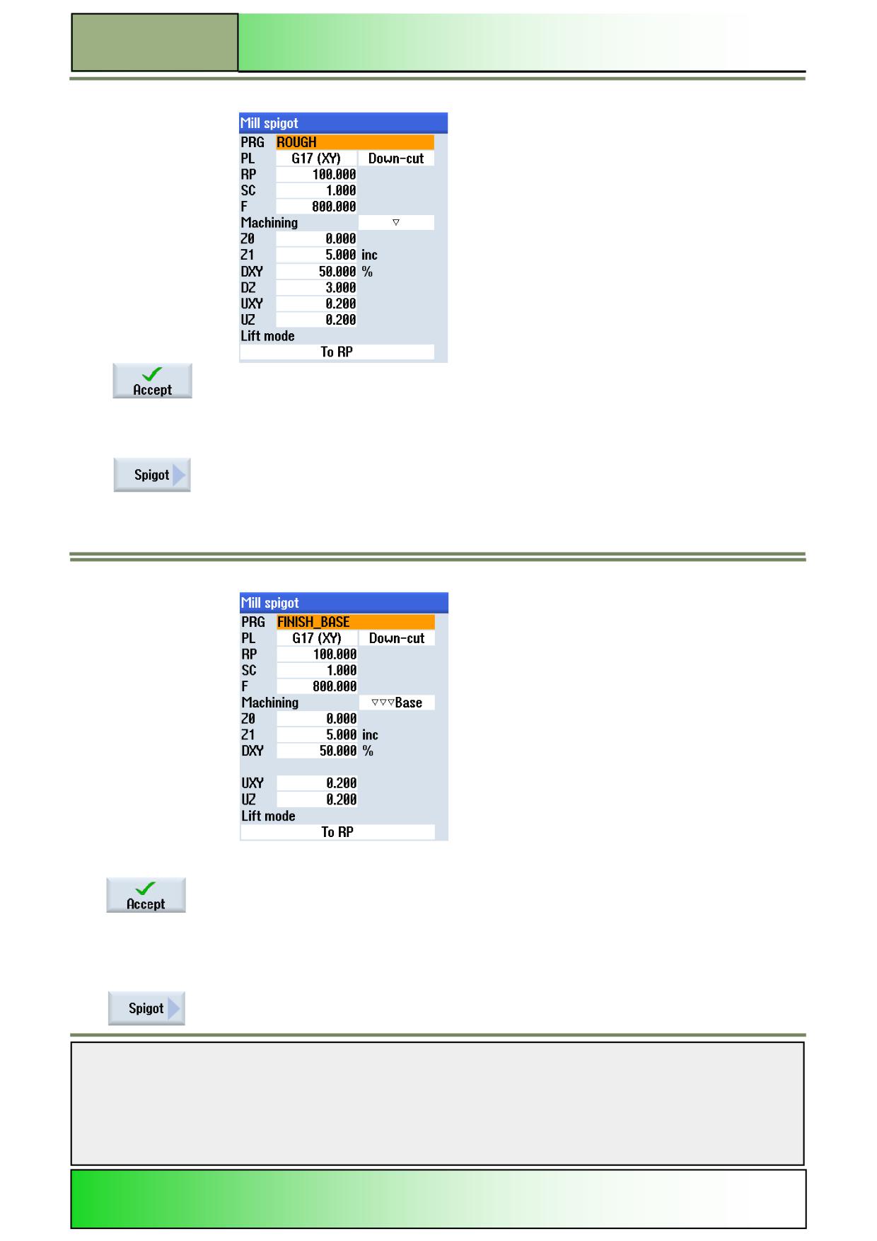
11.
Fill in the input screen as follows:
12.
Confirm the entries with VSK 8 “Accept”.
13.
The following line is inserted in the program:
N110 CYCLE63("ROUGH",1001,100,0,1,5, 800,,50,3,0.2,0.2,0,0,0,,,,1,2,,,,0,201,111)
14.
Now press VSK 6 “Spigot”.
The input screen for the “Spigot” milling cycle opens.
15.
Fill in the input screen as follows:
16.
Confirm the entries with VSK 8 “Accept”.
17.
The following line is inserted in the program:
N120 CYCLE63("FINISH_BASE",1003,
100,0,1,5, 800,,50,3,0.2,0.2,0,0,0,,,,1,2,,,,0,201,111)
18.
Now press VSK 6 “Spigot”.
The input screen for the “Spigot” milling cycle opens.
Notes
M661
Page 8
828D/840Dsl SINUMERIK Operate
Contour Milling with programGUIDE
M661
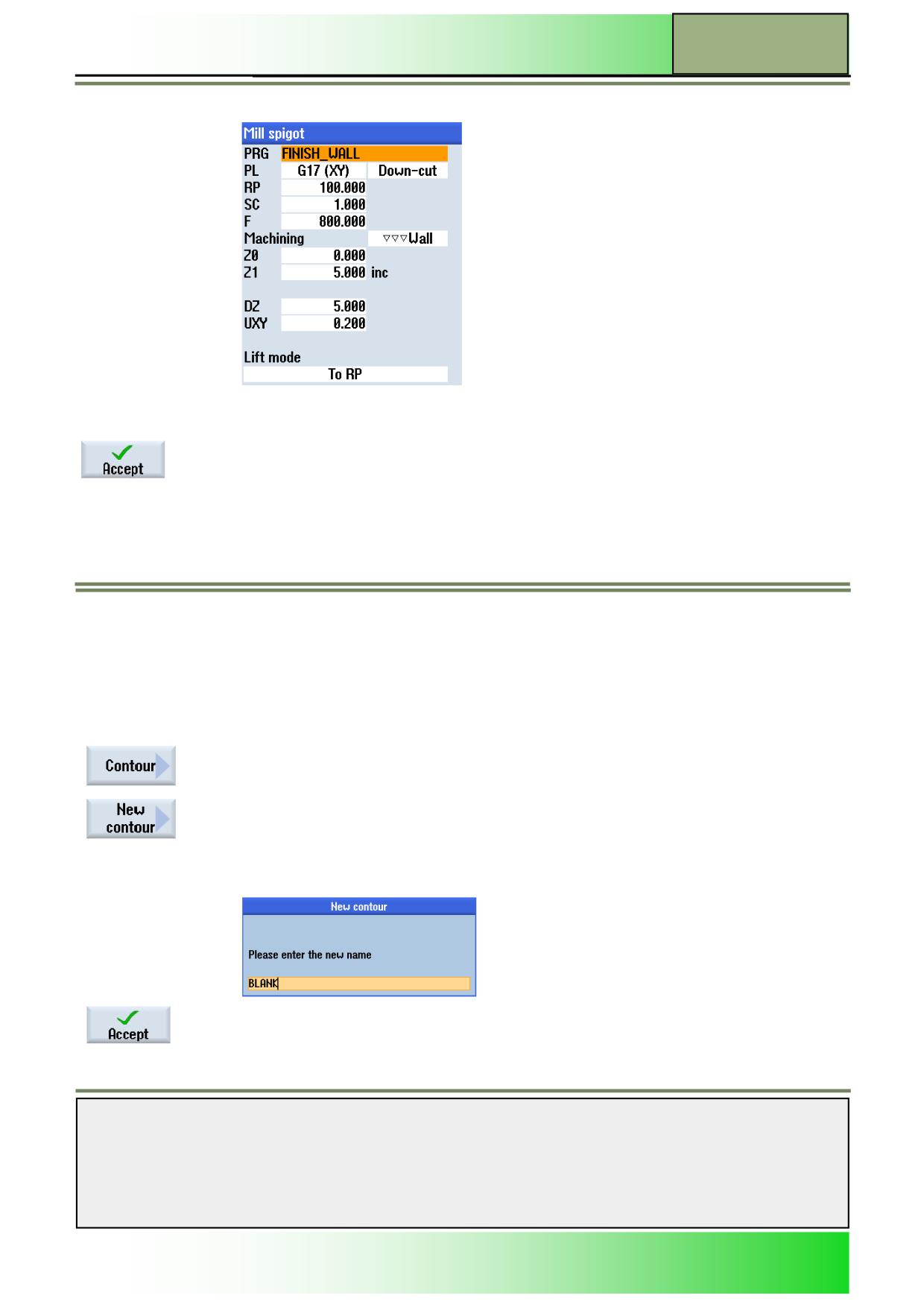
19.
Fill in the input screen as follows:
20.
Confirm the entries with VSK 8 “Accept”.
The following line is inserted in the program:
N130 CYCLE63("FINISH_WALL",1004,
100,0,1,5, 800,,50,5,0.2,0.2,0,0,0,,,,1,2,,,,0,201,111)
21.
Program the following lines manually:
N140 G00 Z100
N150 TRAFOOF
N160 G00 X200 Z200
N170 M30
22.
Now enter the contour definition for the first “BLANK MATERIAL” contour.
Now press VSK 1 “Contour”.
The vertical softkey bar to create and call a new
contour opens.
Press VSK 1 “New contour” to call a new contour.
The input screen to assign a contour name opens.
t contour:
23.
Confirm the entries with VSK 8 “Accept”.
The contour editor with the input screen for the contour definition opens automatically.
Enter the starting point of the contour:
Notes
828D/840Dsl SINUMERIK Operate
Page 9
M661
M661
Contour Milling with programGUIDE
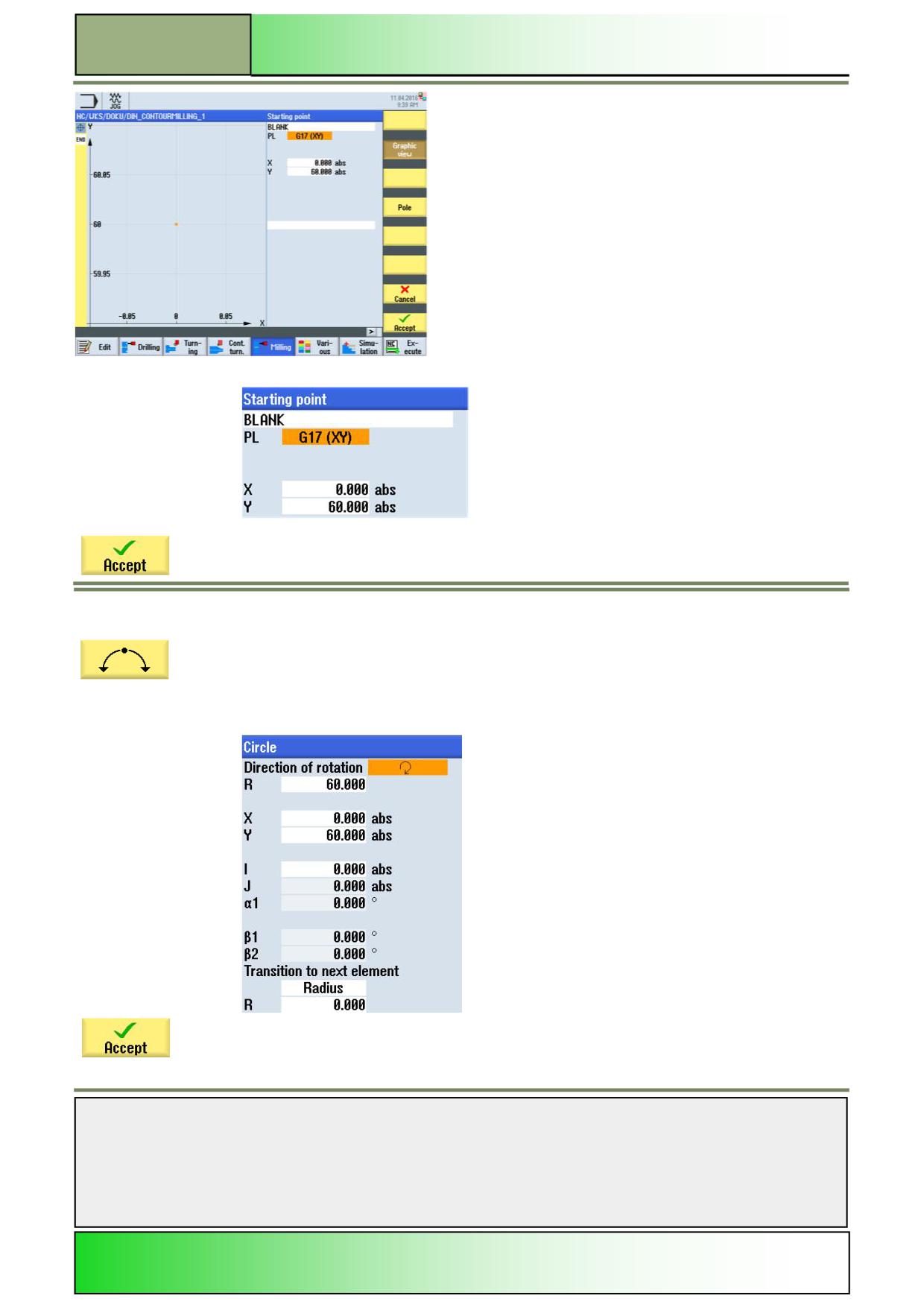
24.
Enter the following coordinates as starting point:
Confirm the entries with VSK 8 “Accept”.
25.
Extend the contour with a circular movement in the clockwise direction.
Press VSK 1.5 “Circle”.
The input window for the contour element of a
circular movement opens.
26.
Enter the coordinates as follows:
Confirm the entries with VSK 8 “Accept”.
Notes
M661
Page 10
828D/840Dsl SINUMERIK Operate
Contour Milling with programGUIDE
M661
Note:
(When entering the circle center point in X (“I”), a dialog selection is opened. Note the input
screen and the changing color of the graphic if you press the “Select dialog” softkey several
times.
If your entries in the input screen are correct, press the “Accept dialog” softkey to accept these
entries.)
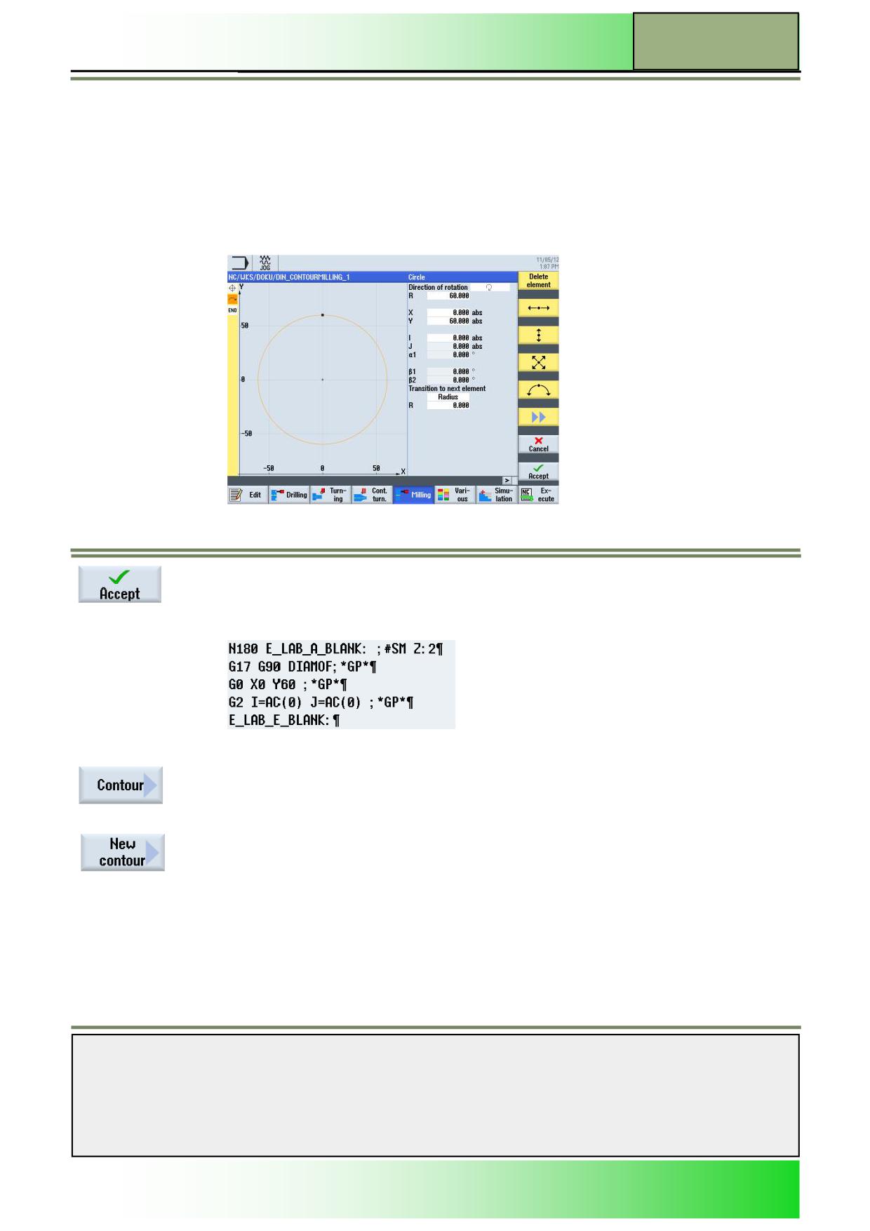
27.
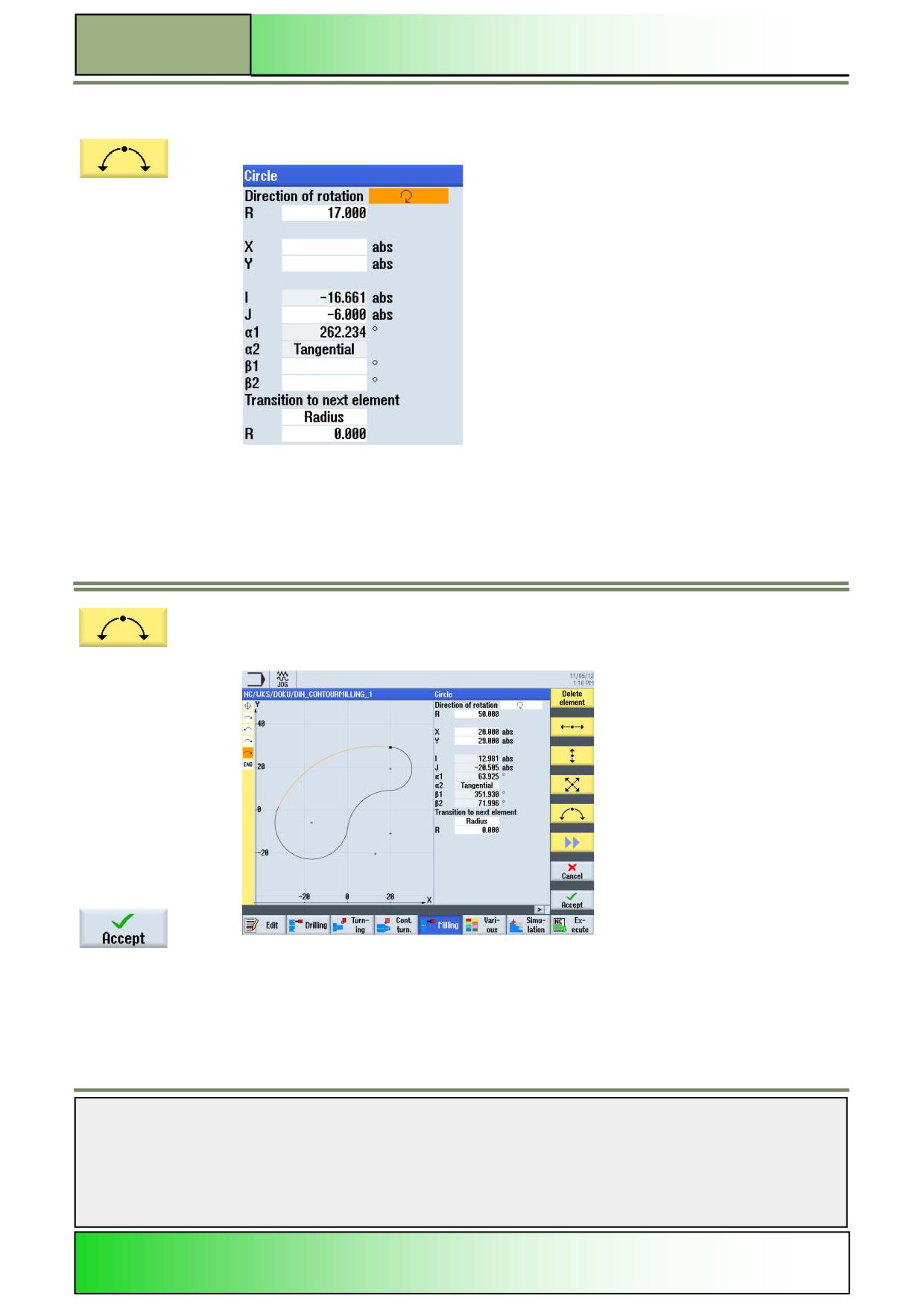
Now check your entries for the first contour. (See figure on the next page.)
The following screen with the finished contour definition is displayed:
Finish the contour definition by pressing VSK 8 “Accept”.
The following G code lines are inserted in the
program:
28.
Now insert the contour definition for the second
contour “KIDNEY”.
Now press VSK 1 “Contour”.
The vertical softkey bar to create and call a new
contour opens.
Press VSK 1 “New contour” to call a new contour.
The input screen to assign a contour name opens.
Notes
828D/840Dsl SINUMERIK Operate
Page 11
M661
M661
Contour Milling with programGUIDE
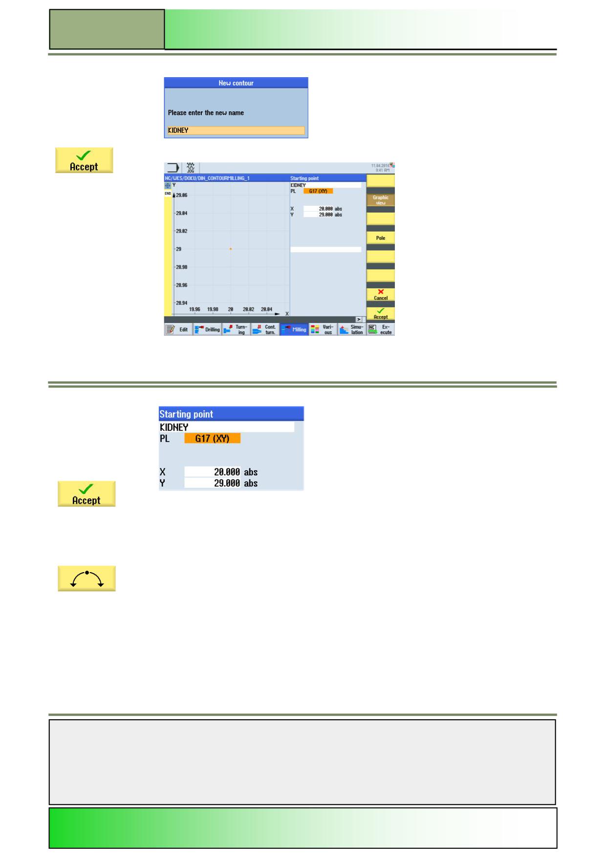
29.
Assign the following name for the second contour:
Confirm the entry with VSK 8 “Accept”.
The contour editor with the input screen for the contour definition opens automatically.
Enter the starting point of the contour:
Confirm the entries with VSK 8 “Accept”.
30.
Extend the contour with a circular movement in the clockwise direction.
Press VSK 1.5 “Circle”.
The input window for the contour element of a circular movement opens.
Notes
M661
Page 12
828D/840Dsl SINUMERIK Operate
Contour Milling with programGUIDE
M661
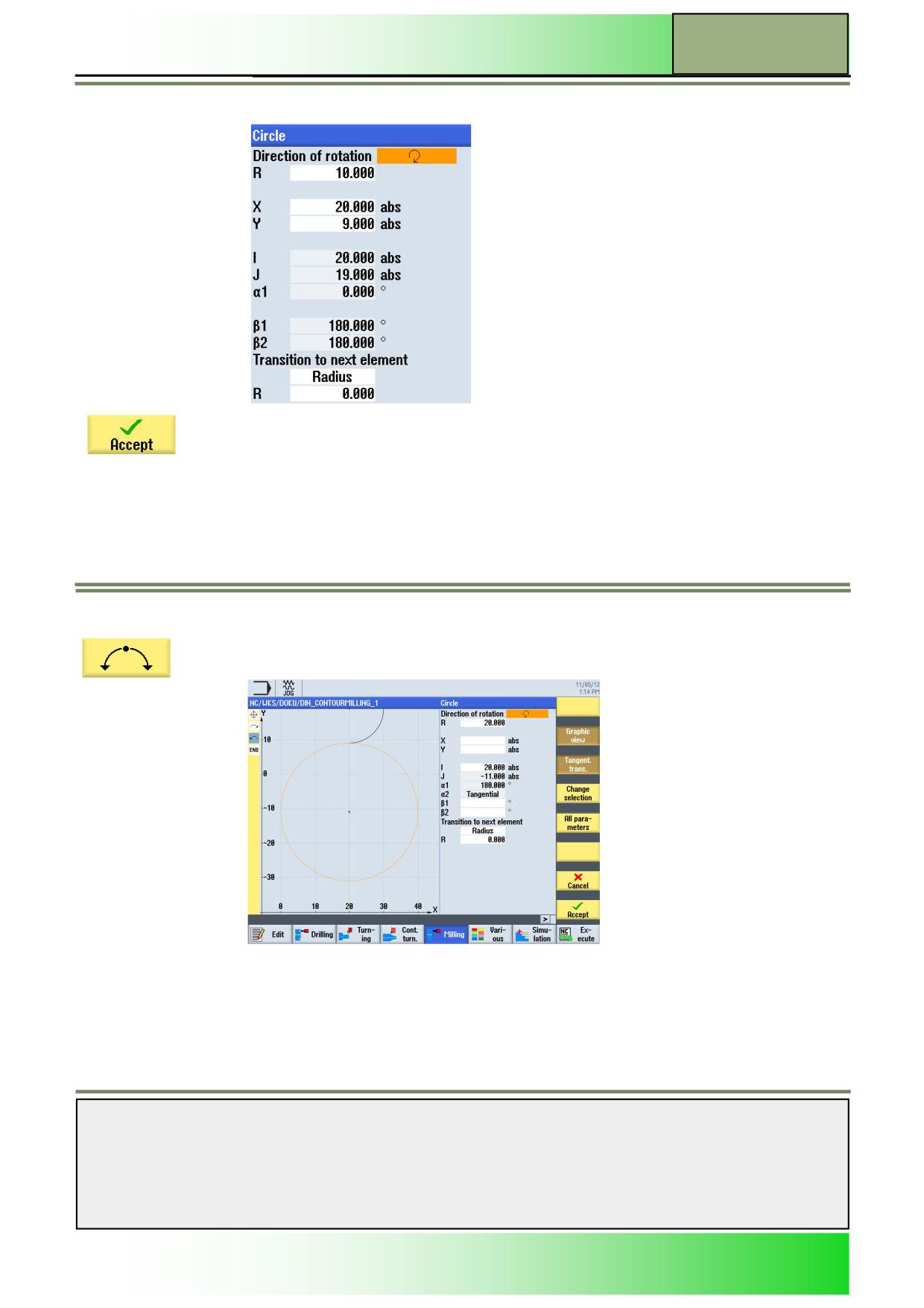
31.
Enter the coordinates as follows:
Confirm the entries with VSK 8 “Accept”.
Note:
(When entering the circle center point in X (“I”), a dialog selection is opened. Note the input
screen and the changing color of the graphic if you press the “Select dialog” softkey several
times.
If your entries in the input screen are correct, press the “Accept dialog” softkey to accept
these entries.)
32.
Extend the contour with a circular movement in the clockwise direction.
Press VSK 1.5 “Circle”.
The input window for the contour element of a circular movement opens.
Note:
(When entering the parameters, activate the “Tangent prev. elem.” softkey to receive the
tangential transition to the previous element.)
Notes
828D/840Dsl SINUMERIK Operate
Page 13
M661
M661
Contour Milling with programGUIDE
33.
Extend the contour with a circular movement in the clockwise direction.
Press VSK 1.5 “Circle”.
The input window for the contour element of a circular movement opens.
Note:
(When entering the parameters, activate the “Tangent prev. elem.” softkey to receive the tan-
gential transition to the previous element.)
34.
Extend the contour with a circular movement in the clockwise direction.
Press VSK 1.5 “Circle”.
The input window for the contour element of a
circular movement opens.
35.
Finish the contour definition by pressing VSK 8 “Accept”.
Notes
M661
Page 14
828D/840Dsl SINUMERIK Operate
Contour Milling with programGUIDE
M661
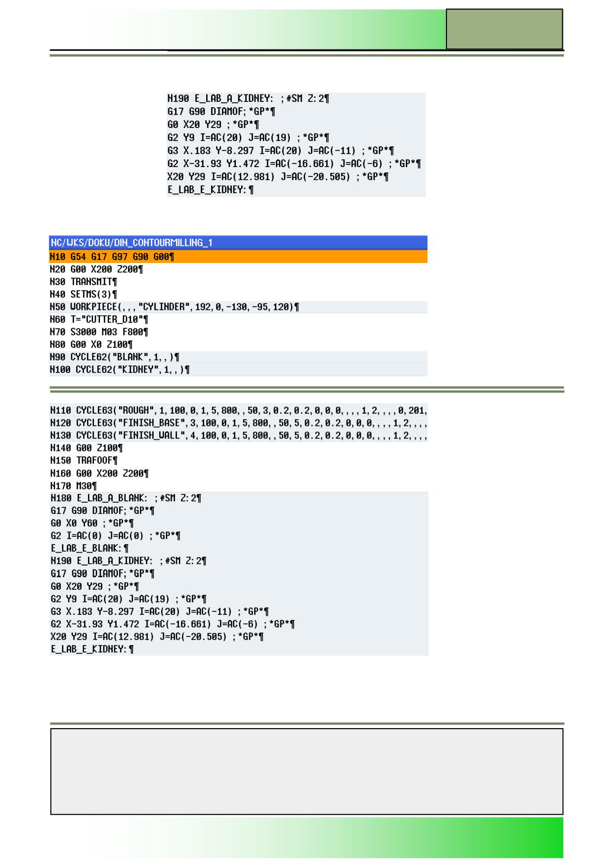
36.
The following G code lines are inserted in the
program:
Notes
828D/840Dsl SINUMERIK Operate
Page 15
M661
M661
Contour Milling with programGUIDE
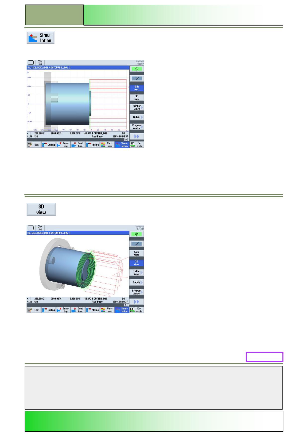
Press HSK 1.7 “Simulation” to start the simulation of the program.
The control calculates the simulation and opens the Simulation window as standard with the
“Side view” of the blank.
To view the simulation on the face end of the blank, press VSK 1.4 “3D view”.
M661: END
Notes
M661
Page 16
828D/840Dsl SINUMERIK Operate
M522
Operating mode “AUTO”
Sinumerik
Operate
Module Description:
This module describes, how to overstore technological parameters (for example, auxiliary
functions, axis feed, spindle speed, programmable instructions, etc.) for a program run in the
main memory of the NCK.
It is described among other things, how the execution of a program can be stopped at a specific part
of the program run with the function “Program control“ (programmed stop).
The differences between the two block search modes (with or without calculation) will be explained in
detail, finally the functions “Settings” complete this module.
Module Objective:
In this module you learn the different options of the operating mode "AUTO" in the oper-
ating area "Machine".
Content:
Operating mode “AUTO“
Overstore
Program control
Block search
Simultaneous recording
Program correction
Settings
This document was produced for training purposes.
828D/840Dsl SINUMERIK Operate v4.7
Page 1
M522
Siemens assumes no responsibility for its contents.
M522
M522
Page 2
828D/840Dsl SINUMERIK Operate

Operating mode “AUTO”
M522
Operating mode
AUTO:
START
Operating
mode “AUTO“
Overstore
Program
control
Block search
Simultaneous
recording
Program
correction
Setting
Operating mode
AUTO:
END
Notes
828D/840Dsl SINUMERIK Operate
Page 3
M522
M522
Operating mode “AUTO”
Operating mode "AUTO"
Selecting the operating mode “AUTO”
The operating mode “AUTO” can be selected as follows:
Press the “AUTO“ button on the machine control panel (MCP).
The operating mode “AUTO” opens directly.
- OR -
Press the button “MENU SELECT“ on the machine control panel.
Press the VSK 1 “AUTO“ in the yellow VSK-bar on the right hand side of the screen to switch
directly to the operating mode “AUTO“.
Next, switch to the operating area “Machine” by pressing the “MACHINE”-key on the operator
panel or the keyboard else press the “MENU SELECT“-key on the operator panel and the yel-
low HSK 1 “Machine“.
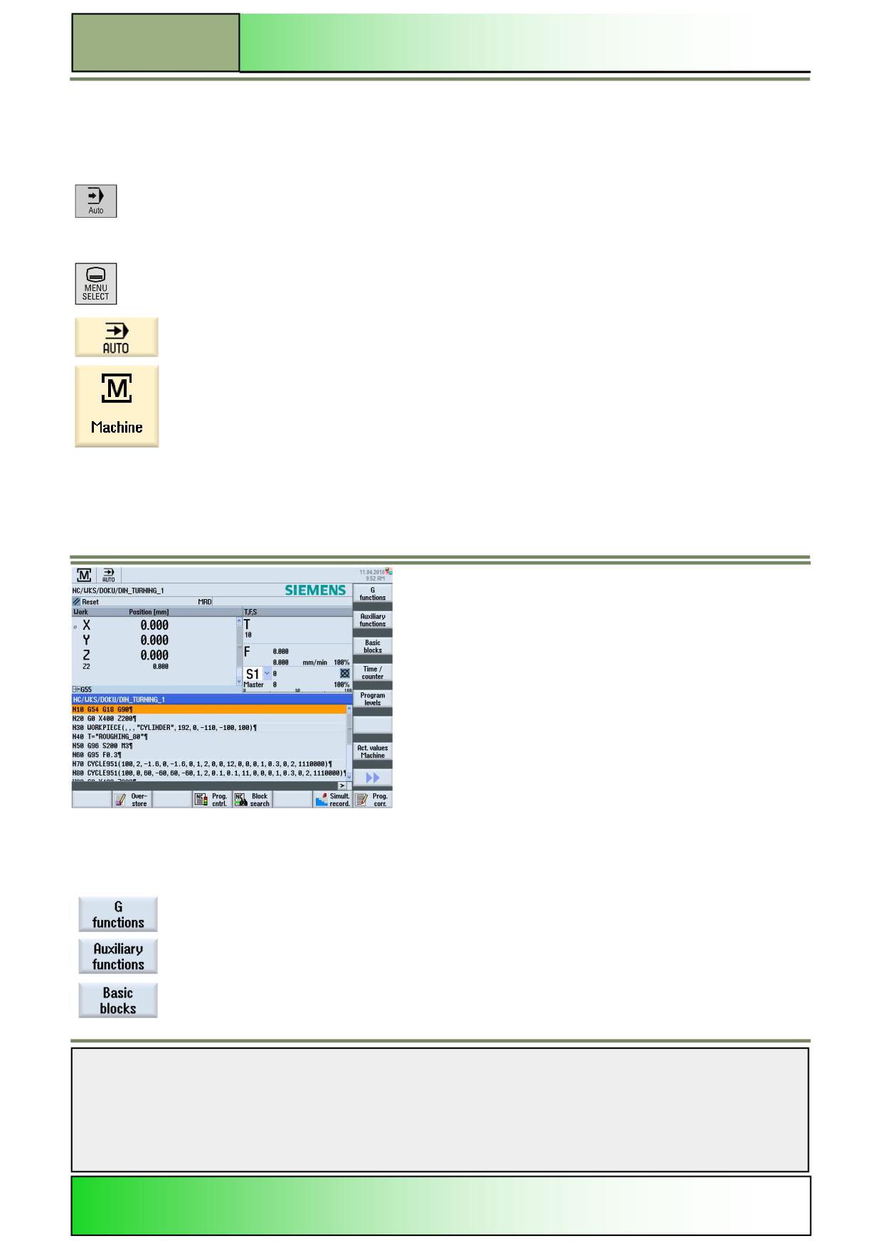
The following screen opens:
The following softkeys will be shown in the vertical and horizontal softkey bars:
Vertical softkey bar 1 and 2
Display area
Description
By pressing the VSK 1.1 “G functions“ the most important G-functions will be displayed.
By pressing the VSK 1.2 “Auxiliary functions“, available auxiliary functions will be displayed
at the time of the output.
By pressing the VSK 1.3 “Basic blocks“ all G-code commands that trigger a function on the
machine will be displayed. The display updates both in the test operation and in the actual
machining of the workpiece at the machine.
Notes
M522
Page 4
828D/840Dsl SINUMERIK Operate
Operating mode “AUTO”
M522
Display area
Description (continuation)
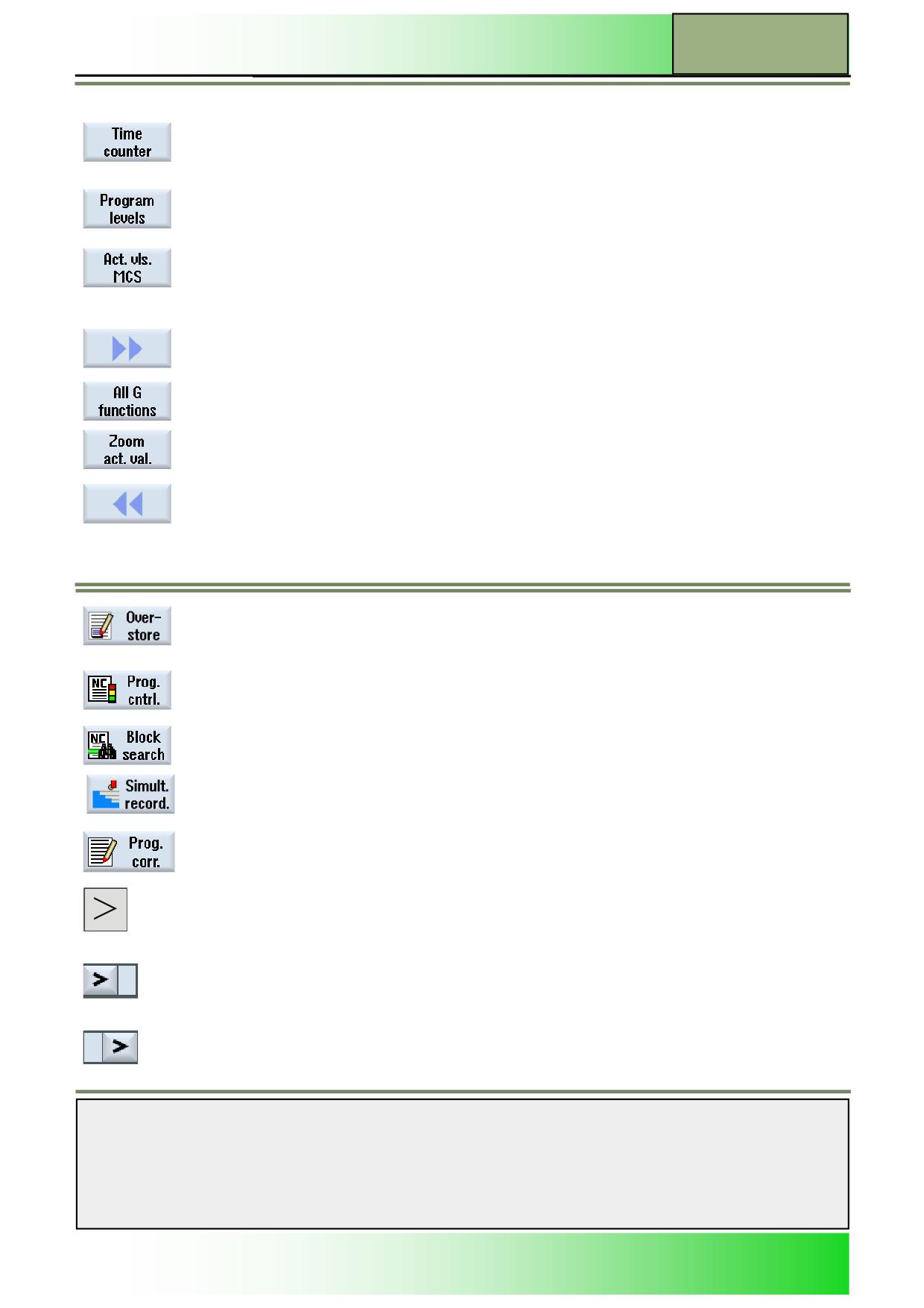
By pressing the VSK 1.4 “Time counter“ the program run time, the rest of the program run time
and the amount of machined workpieces will be displayed.
Note: Refer to the machine manufacturer’s documentation.
By pressing the VSK 1.5 “Program levels“ you can display the current program level during the
execution of a large program with several subprograms.
By pressing the VSK 1.7 “Act vls. MCS” you can switch over from the machine coordinate sys-
tem (MCS) to the workpiece coordinate system (WCS).
Note:
Refer to the machine manufacturer’s documentation.
By pressing the VSK 1.8 "Extend" on the operator panel (OP) you switch to the vertical softkey
bar 2 with additional softkeys displayed.
By pressing the VSK 2.2 “All G functions” all G-functions will be displayed.
By pressing the VSK 2.6 “Zoom act. val.“ all actual values will be displayed full-screen.
By pressing the VSK 2.8 “Back” on the operator panel you can switch back to the vertical soft-
key bar 1.
Horizontal softkey bar 1 and 2
Display area
Description
Pressing the HSK 1.2 “Overstore” allows you to overstore technological parameters (for exam-
ple, auxiliary functions, axis feed, spindle speed, programmable instructions, etc.) for a program
run in the main memory of the NCK.
By pressing the HSK 1.4 “Prog. cntrl.” the working window for controlling the program run will
be opened.
By pressing the HSK 1.5 “Block search” the block search window opens.
By pressing the HSK 1.7 “Simultaneous recording“ you can graphically display the execution
of the program on the screen before or during machining of the workpiece, to monitor the result
of the programming.
By pressing the HSK 1.8 “Prog. corr.“ (program correction) the program editor opens.
By pressing the "Extend"-button on the operator panel you can switch between the normal and
the extended horizontal softkey bar.
This symbol on the right of the dialogue line indicates that more softkeys are available on the
extended horizontal softkey bar.
This symbol indicates that the extended horizontal softkey bar is shown on the screen. You can
switch back to the HSK 1 again by pressing the “Extend”-key.
Notes
828D/840Dsl SINUMERIK Operate
Page 5
M522
M522
Operating mode “AUTO”
Display area
Description (continuation)
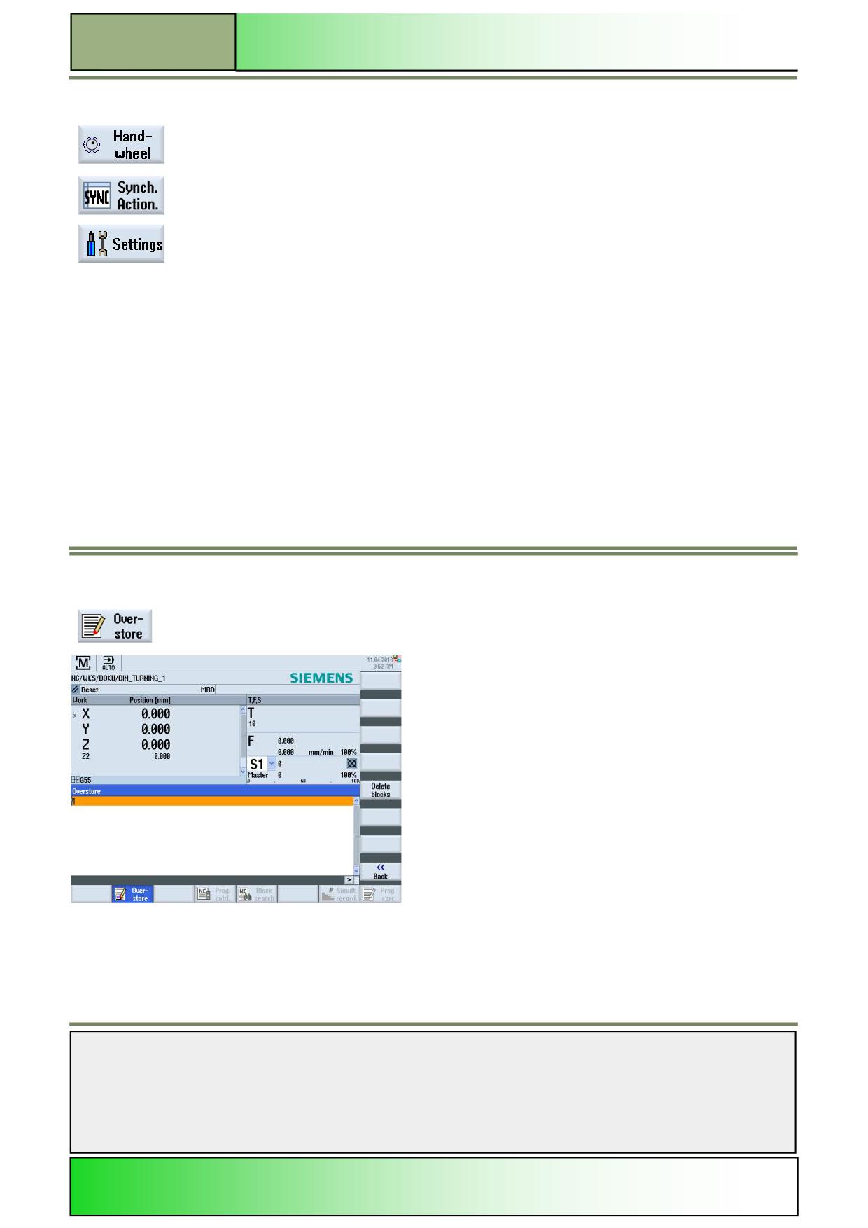
By pressing the HSK 2.6 "Handwheel" the input mask for assigning axes to all parameterized
handwheels is displayed.
By pressing the HSK 2.7 "Synchr. Action." the screen which shows the current synchronized
actions is displayed.
By pressing the HSK 2.8 "Settings" a window opens up where you can adjust the settings for
manual operation on the Sinumerik Operate.
Overstore
Selecting the Function “Overstore“
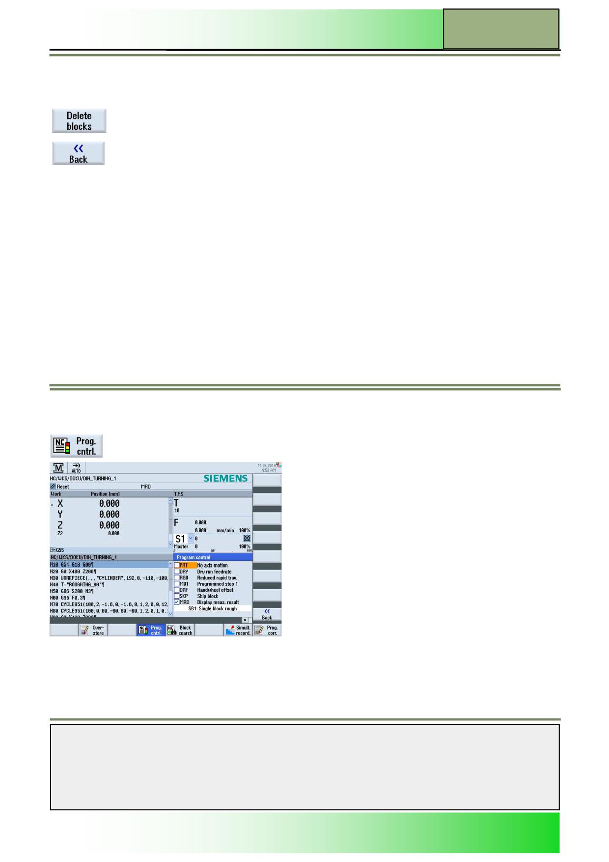
By pressing the HSK 1.2 “Overstore“ the “Overstore” window opens (see picture below).
The program to be corrected has to be in the STOP or RESET mode.
In the “Overstore” editor view you can overstore technological parameters (for example, auxiliary functions, axis feed, spin-
dle speed, programmable instructions, etc.) for a program run in the main memory of the NCK.
The programs in the part program memory are not changed while using the function “Overstore”.
You cannot change the operating mode while you are in overstore mode.
Notes
M522
Page 6
828D/840Dsl SINUMERIK Operate
Operating mode “AUTO”
M522
Vertical softkey bar
Display area
Description
By pressing the VSK 1.5 “Delete blocks” you can delete the blocks you have entered before.
By pressing the VSK 1.8 “Back“ the window is being closed. A change of the operation mode is
now possible. Press “CYCLE START“ to continue running the previously selected program.
Procedure for „Overstore“
1.
Open a program in the operating mode “AUTO” then press the HSK 1.2 “Overstore”. The “Overstore” window
opens.
2.
Enter the required data and NC block.
3.
Press the “CYCLE START” key. The blocks you have entered are stored. You can observe execution in the
"Overstore" window. After the entered blocks have been executed, you can append blocks again.
4.
Press the VSK 8 "Back". The "Overstore" window closes.
5.
Press the “CYCLE START” key again.
The program selected before overstoring continues to run.
Program control
Selecting the function “Program control”
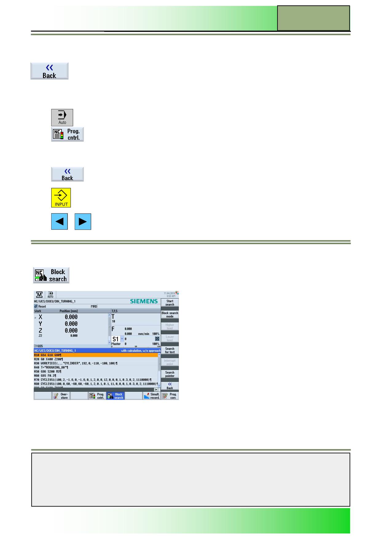
By pressing the HSK 1.4 “Prog. cntrl.“ the “Program control” window opens like displayed
below:
Notes
828D/840Dsl SINUMERIK Operate
Page 7
M522

M522
Operating mode “AUTO”
Navigation through the option menu takes place by pressing the blue Cursor keys on the key-
board.
You can activate or deactivate an option by selecting the entry first and then pressing the blue
“SELECT“ key.
The following program control options are selectable:
Abbreviation/Program
Scope
control
PRT
The program is started and executed with auxiliary function outputs and dwell times. In this
No axis motion
mode, the axes are not traversed.
The programmed axis positions and the auxiliary function outputs are controlled this way.
Note:
Program processing without axis motion can also be activated with the function "Dry run
feedrate".
DRY
The traversing velocities programmed in conjunction with G1, G2, G3, CIP and CT are re-
Dry run feedrate
placed by a defined dry run feedrate. The dry run feedrate also applies instead of the pro-
grammed revolutional feedrate.
Caution:
Workpieces must not be machined when "Dry run feedrate" is active because the altered
feedrates might cause the permissible tool cutting rates to be exceeded and the workpiece or
machine tool could be damaged.
RG0
In the rapid traverse mode, the traversing speed of the axes is reduced to the percentage value
Reduced rapid trav.
entered in RG0.
M01
The processing of the program stops at every block in which supplementary function “M01” is
Programmed stop 1
programmed. In this way you can check the already obtained result during the processing of a
workpiece.
Note:
In order to continue executing the program, press the "CYCLE START" key again.
Programmed stop 2
The processing of the program stops at every block in which the "Cycle end" is programmed
(e.g. M201)
(e.g. with “M201”).
Note:
In order to continue executing the program, press the "CYCLE START" key again.
The display can be changed. Please also refer to the machine manufacturer's instructions.
DRF
Enables an additional incremental zero offset while processing in automatic operation mode
Handwheel offset
with an electronic handwheel.
This function can be used to compensate for tool wear within a programmed block.
SB
Individual blocks are configured as follows:
SB 1 - Single block, coarse: The program stops only after blocks which perform a machine
function.
SB 2 - Data block: The program stops after each block.
SB 3 - Single block, fine: The program stops also in cycles after blocks, which perform a
machine function.
Select the desired setting using the "SELECT" key on the keyboard.
The selection of the function “Single block” takes place by pressing the “SINGLE BLOCK”-key
on the machine control panel (MCP).
SKP
Skipped blocks are skipped during machining.
MRD
In the program, the measurement results screen display is active while machining.
Notes
M522
Page 8
828D/840Dsl SINUMERIK Operate
Operating mode “AUTO”
M522
Vertical softkey bar
Display area
Description
By pressing the VSK 8 “Back” you return to the window “Program control”.
Controlling the program run
1.
In the operating mode “AUTO“ and the operating area “Machine” press the HSK 4 “Prog.
cntrl.“.
The “Program control” window opens and shows a list of program control options.
2.
Select the desired program control (see section 4.1 in this module).
3.
Press the VSK 8 “Back” to go back to the main screen of the Sinumerik Operate in the operat-
ing mode “AUTO” and operating area “Machine”.
Hint:
The orange selection cursor disappears, if a skip block is confirmed with the yellow “INPUT”-
key.
With the blue “cursor to the left” or “cursor to the right” you return again to the selection
mode.
Block search
Selecting the function “Block search”
By pressing the HSK 1.5 “Block search” the “block search” window opens as shown below.
Notes
828D/840Dsl SINUMERIK Operate
Page 9
M522
M522
Operating mode “AUTO”
If you would only like to perform a certain section of a program on the machine, then you don’t have to start the program
from the beginning. You can also start the program from a specified program block.
Applications of this function are to stop or interrupt program execution and to specify a target position (e.g. during machin-
ing).
Determination of search targets per:
a. Comfortable search target definitions (search positions)
Direct specification of the search target by positioning the cursor in the selected program (main program).
Search target via text search.
The search target is the interruption point (main program and subprogram). The function is only available if there is an
interruption point. After a program interruption (“CYCLE STOP” or “RESET”), the controller saves the coordinates of the
interruption point.
The search target is the higher program level of the interruption point (main program and subprogram). The level can
only be changed if it was previously possible to select an interruption point in a subprogram. It is then possible to
change the program level up to the main program level and back to the level of the interruption point.
OR -
b. Search pointer
Direct entry of the program path in the “Search pointer“ window.
If a search target was found, it is possible to start another search run immediately. This can be done many times after eve-
ry successful search run.
Attention:
Pay attention to a collision-free starting position as well as accurate active tools and other technological values. If neces-
sary move the tool to a save starting position. Select the target block considering the selected block search type.
Navigation through the program blocks takes place by using the blue cursor-keys on the key-
board.
The following functions are available in the vertical softkey bar:
Notes
M522
Page 10
828D/840Dsl SINUMERIK Operate
Operating mode “AUTO”
M522
Vertical softkey bar
Display area
Description
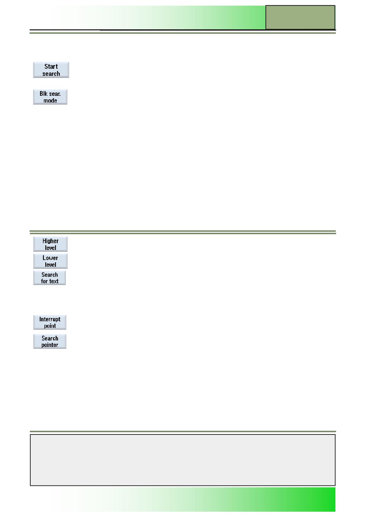
By pressing the VSK 1 “Start search“ the search run starts depending on the search mode
you have selected before. Press the VSK 1 several times, until the found target (z.B. with
search text) corresponds to the searched program block.
By pressing the VSK 2 “Blk. sear. mode“ the “Block search mode” window opens.
Two different block search modes are selectable:
With calculation:
Without approach:
It is used in order to be able to approach a target position in any circumstance (e.g. tool
change position). The end position of the target block or the next programmed position is
approached using the type of interpolation valid in the target block. Only the axes pro-
grammed in the target block are moved.
With approach:
It is used to be able to approach the contour in any circumstance. The end position of the
block prior to the target block is found with "CYCLE START". The program runs in the
same way as in normal program processing.
Display area
Description (continuation)
Without calculation:
For a quick search in the main program. Calculations will not be performed during the
block search, i.e. the calculation is skipped up to the target block. All settings required for
execution have to be programmed from the target block (e.g. feedrate, spindle speed,
etc.).
Pressing the VSK 3 “Higher level“ changes the program level to one level higher.
Pressing the VSK 4 “Lower level“ changes the program level to one level lower.
By pressing the VSK 5 “Search for text“ the “Search” window opens. After entering the
search direction in the “Direction” field and the search text in the “Text” field and by pressing
the VSK 8 “OK” the search run starts. After a successful search you can search for the same
search parameter again, by pressing the VSK 8 “Continue search”.
The search can be cancelled by pressing the VSK 7 “Cancel”. A new search run with new
search parameters can be initiated with the VSK 4 “Search”.
By pressing the VSK 6 “Interrupt point” the program that was interrupted before, by pressing
the “RESET” key, will be executed again.
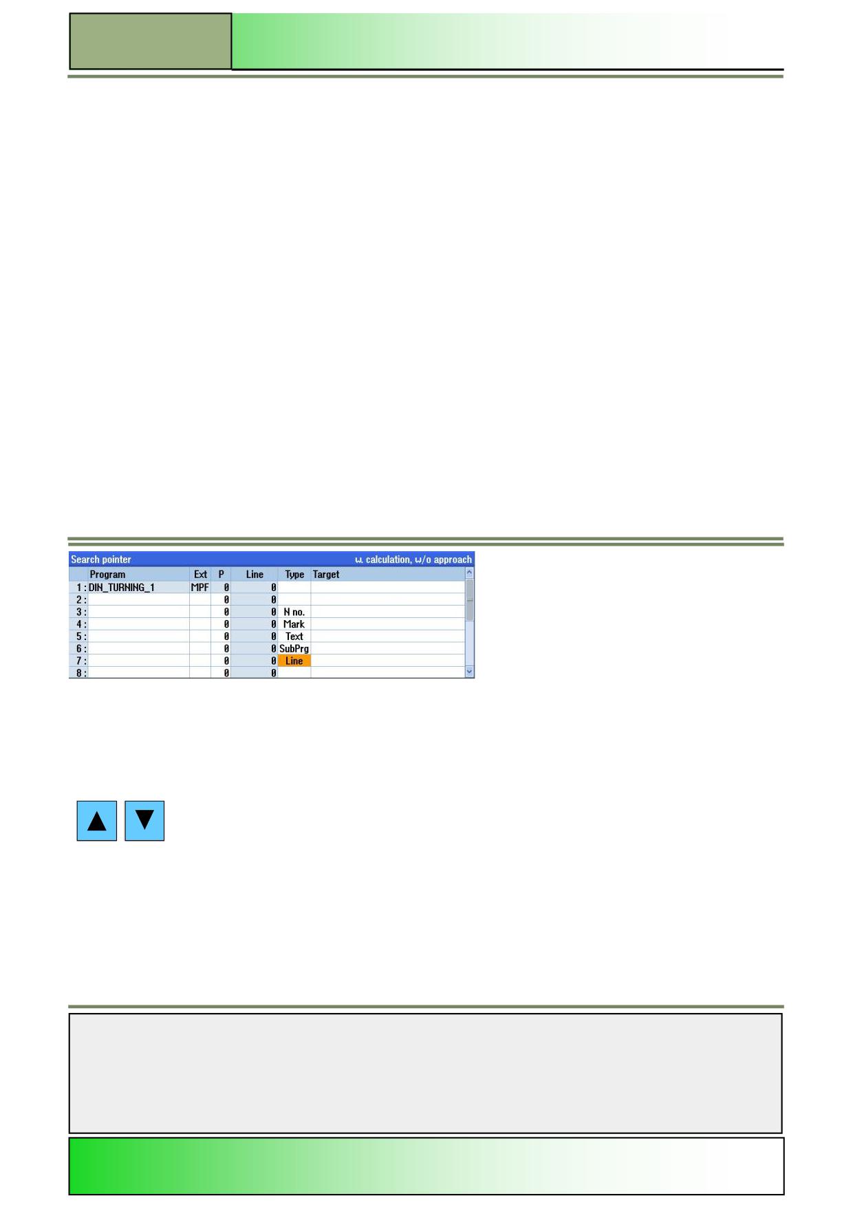
By pressing the VSK 7 “Search pointer“ you can jump directly to a desired part of the pro-
gram.
The following options are available in a list in the “Search pointer” window:
Program
The name of the currently loaded program is automatically entered
Ext.
File extension
P
Pass counter: If a program section is performed several times, you can enter the number
of the pass here at which processing is to be continued
Line
Is automatically filled for an interruption point
Notes
828D/840Dsl SINUMERIK Operate
Page 11
M522
M522
Operating mode “AUTO”
Display area
Description (continuation)
Type
N no.:
Block number
Label:
Jump label
Text:
Text string
Subprg.:
Subprogram call
Line:
Line number
Search target
Search target point in the program at which machining is to start
By pressing the VSK 8 “Back” the “Search” window closes.
Starting a block search
1.
A desired program is selected and the machining was discontinued with pressing “RESET” or
“CYCLE STOP“ or the control unit is generally in RESET state.
2.
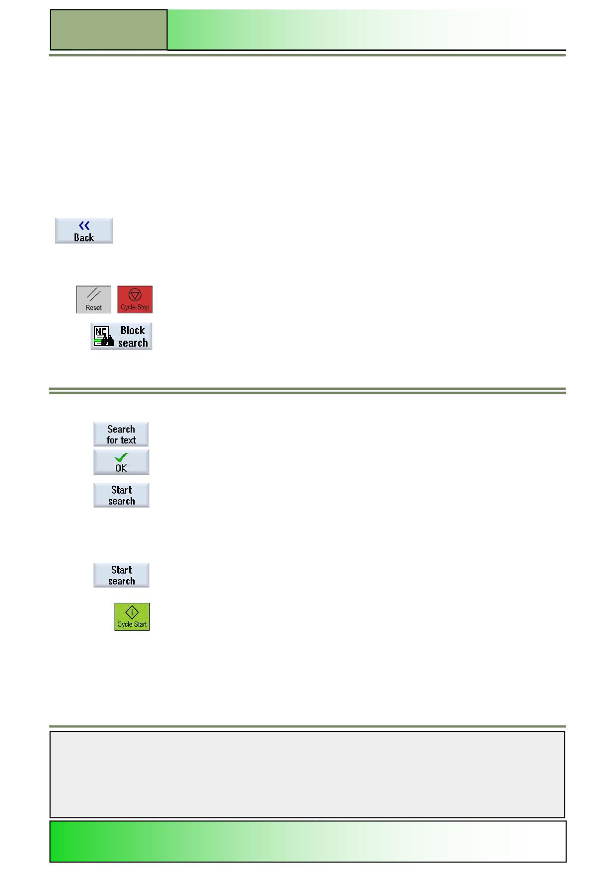
In the operating mode “AUTO“ and the operating area “Machine” press the HSK 5 “Block
search”.
For further steps see below:
Simple search target definition:
Steps 1 and 2 (see above).
3.
Place the cursor on a particular program block.
- OR -
Press the VSK 5 "Search for text", select the search direction, enter the search text and con-
firm with the VSK 8 "OK".
4.
Press the VSK 1 “Start search“.
The search starts.
Your specified search mode will be taken into account (indicated in the upper blue title bar of
the search target window). The current block will be displayed and marked in the "Program"
window as soon as the target is found.
5.
If the located target (for example, when searching via text) does not correspond to the pro-
gram block, press the "Start search" softkey again until you find your target.
6.
Press the "CYCLE START"-key twice.
Processing is continued from the defined position.
Notes
M522
Page 12
828D/840Dsl SINUMERIK Operate
Operating mode “AUTO”
M522
Interruption point as search target:
1. - 2.
Steps 1 and 2 (see above).
3.
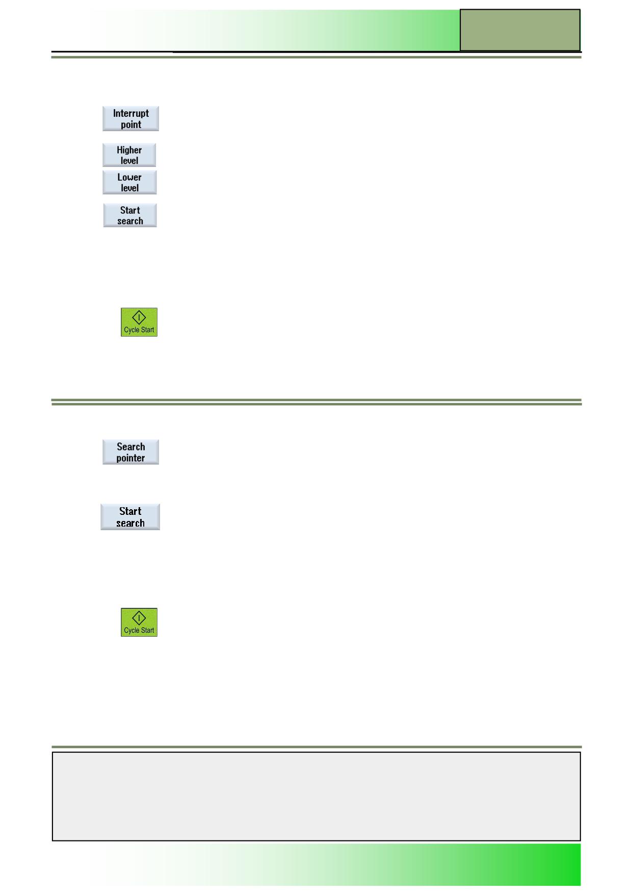
Press the VSK 6 “Interrupt point“
The interruption point is loaded.
4.
If the VSK 3 "Higher level" and the VSK 4 "Lower level" are available, use these to change the
program level.
5.
Press the VSK 1 "Start search".
The search starts.
The specified search mode will be taken into account (indicated in the upper blue title bar of the
search target window).
The search screen closes.
The current block will be displayed and marked in the "Program" window as soon as the target
is found.
6.
Press the "CYCLE START"-key on the machine control panel (MCP) twice.
The execution will continue from the interruption point.
Search target via search pointer:
Steps 1 and 2 (see above).
3.
Press the VSK 7 “Search pointer”.
The “Search pointer” window opens.
4.
Enter the full path of the program as well as the subprograms, if required, in the input fields.
5.
Press the VSK 1 “Start search”.
The search starts.
The specified search mode will be taken into account (indicated in the upper blue title bar of the
search target window).
The search screen closes.
The current block will be displayed and marked in the "Program" window as soon as the target
is found.
6
Press the "CYCLE START" key on the machine control panel twice.
Processing is continued from the defined location.
Notes
828D/840Dsl SINUMERIK Operate
Page 13
M522
M522
Operating mode “AUTO”
Simultaneous recording
Selecting the function “Simultaneous recording”
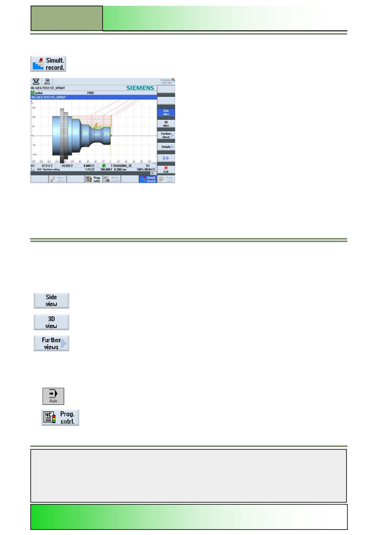
Pressing the HSK 1.7 “Simult. Record.“ opens the simultaneous recording window.
Before machining the workpiece on the machine, you can graphically display the execution of the program on the screen to
monitor the result of the programming. You can replace the programmed feedrate with a dry run feedrate to influence the
speed of execution.
Simultaneous record can also be turned on, if machining is already running. You can also use simultaneous recording dur-
ing machining of a workpiece. This helps if the view towards the inside of the cabin is obstructed by coolant. In each differ-
ent view of the “Simultaneous recording” window you can adjust the view by using the blue cursor keys and zoom in or out
by using the plus (“+”) and minus (“-”) keys on the keyboard. The traversing paths of the tool in the “Simultaneous record-
ing” window are displayed in different colours: red for rapid traverse and green for feed motion.
The following softkeys, each representing a different view on the simulated workpiece, are available on the vertical softkey
bars.
Vertical softkey bar 1 and 2
Display area
Description
By pressing the VSK 1.3 “Side view” the work piece will be shown in a plan view from the
top.
By pressing the VSK 1.4 “3D view“ the work piece will be shown in a 3-D view.
By pressing the VSK 1.5 “Further views“ the vertical softkey bar 3 opens with options to
change to different views of the workpiece.
Simultaneous recording of a program run
Simultaneous recording before machining of the workpiece
1.
Load a program in the operating mode “AUTO”.
2.
Press the HSK 1.4 “Prog. cntrl.“ and activate the checkboxes "PRT No axis motion" and "DRY
Dry run feedrate".
The program is executed without axis movement. The programmed feedrate is replaced by a dry
run feedrate.
Notes
M522
Page 14
828D/840Dsl SINUMERIK Operate
Operating mode “AUTO”
M522
2.
-OR-
Let the “DRY Dry run feedrate” box unchecked.
Simultaneous recording is performed with the programmed feedrate.
3.
Press the HSK 7 “Simult. record“.
The “Simultaneous recording” window opens.
4.
Press the “CYCLE START” key on the machine control panel (MCP).
The execution of the program on the machine is started and displayed graphically on the screen.
5.
Press “CYCLE STOP” to stop machining and the HSK 7 "Simult. record" again to close the
“Simultaneous recording” window.
Simultaneous recording during machining of the workpiece
1.
Load a program in the operating mode “AUTO”.
2.
Press the HSK 7 “Simult. record“.
The “Simultaneous recording” window opens.
3.
Press the “CYCLE START”-key on the machine control panel (MCP).
The machining of the workpiece is started and graphically displayed on the screen.
4.
Press the “CYCLE STOP”-key and the HSK 7 "Simultan. record" again to stop the recording
and to close the “Simultaneous recording” window.
Program correction
As soon as a syntax error in the part program is detected by the controller, program execution is interrupted and the syntax
error is displayed in the alarm line.
Depending on the state of the control, you can make the following corrections using the “Program correction” function:
STOP mode: Only program lines that have not yet been executed can be edited.
RESET state: All program lines can be edited
Note:
The "Program correction" function is only available for part programs in the NC memory, not for external execution (e.g.
on USB media).
Notes
828D/840Dsl SINUMERIK Operate
Page 15
M522
M522
Operating mode “AUTO”
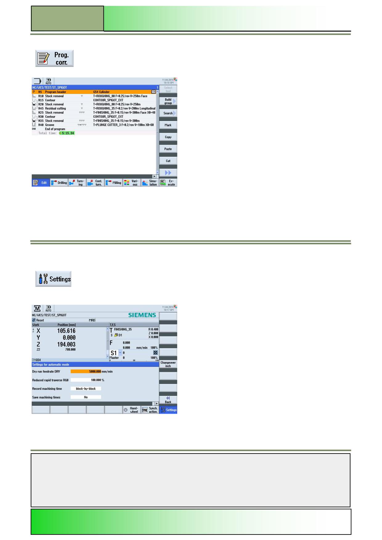
Selecting the function “Program correction”
By pressing the HSK 1.8 “Prog. Corr.“ the program editor window opens for correction of the
program.
Setting
Selecting the function “Settings”
By pressing the HSK 2.8 “Settings” the following input mask with the settings for automatic
mode is shown on the screen.
Notes
M522
Page 16
828D/840Dsl SINUMERIK Operate
Operating mode “AUTO”
M522
Vertical softkey bar (VSK)
Display area
Description
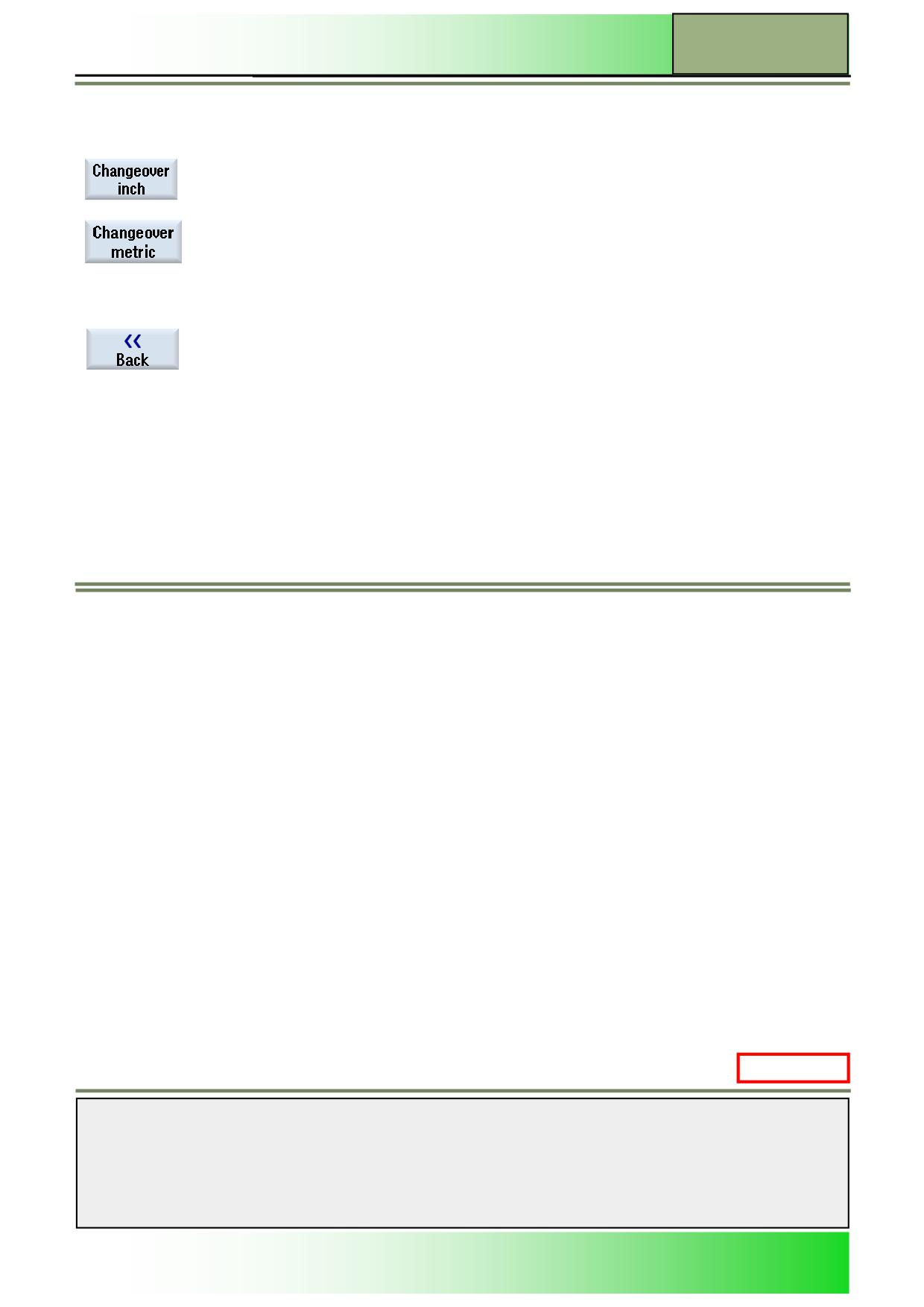
By pressing the VSK 5 "Changeover inch" the measuring units are converted from the metric
to the imperial (inch) dimension system. New values have to be entered in inches. By pressing
this key the key function switches to "Changeover metric".
By pressing the VSK 5 "Changeover metric" the measuring units are converted from the impe-
rial (inch) to the metric dimension system. New values have to be metric. By pressing this key
the key function switches to "Changeover inch".
Accept the selection by pressing the VSK 8 “OK” or
cancel by pressing the VSK 7 “Cancel”.
By pressing the VSK 8 "Back" you switch back to the main screen of the Sinumerik Operate.
Parameters for "Settings for automatic mode"
In the “Settings for automatic mode“ window all configurations for automatic operation can be done.
Parameter
Unit
Meaning
Dry run feedrate
[mm/ min] The feedrate defined here replaces the programmed feedrate during execution if you
have selected „DRY dry run feedrate“ under program control.
DRY
Reduced rapid traverse
[%]
This value entered here reduces the rapid traverse to the entered percentage value if
RG0
you have selected “RG0 reduced rapid traverse” under program control.
Record machine time
The machining times are determined for each block of the main program or deter-
mined for all blocks and shown in the “Working window”, this function can also be
switched off.
Save machining times
A time stamp is placed into the NC program and stored for future reference, or this
function can be switched off.
M522: END
Notes
828D/840Dsl SINUMERIK Operate
Page 17
M522

M522
Operating mode “AUTO”
Notes
M522
Page 18
828D/840Dsl SINUMERIK Operate
M510
Mirror, offset, rotate, scale for turning
Sinumerik
Operate
Module Description:
This module describes the programmable manipulation of the coordinate system and the usage of
dwells.
Module Objective:
In this module you learn to offset the active work piece zero point in the program, scale
the coordinate system and insert dwell times into the program sequence.
Content:
General information about offsets
Offset of the coordinate system
Scaling of the coordinate system
Dwell time
Summary
This document was produced for training purposes.
828D/840Dsl SINUMERIK Operate v4.7
Page 1
M510
Siemens assumes no responsibility for its contents.
M510
M510
Page 2
828D/840Dsl SINUMERIK Operate

Mirror, offset, rotate, scale for turning
M510
Mirror, offset,
rotate, scale:
START
General
information
about offsets
Offset of the
coordinate
system
Scaling of the
coordinate
system
Dwell time
Examples
Mirror, offset,
rotate, scale:
END
Notes
828D/840Dsl SINUMERIK Operate
Page 3
M510
M510
Mirror, offset, rotate, scale for turning
General information about offsets
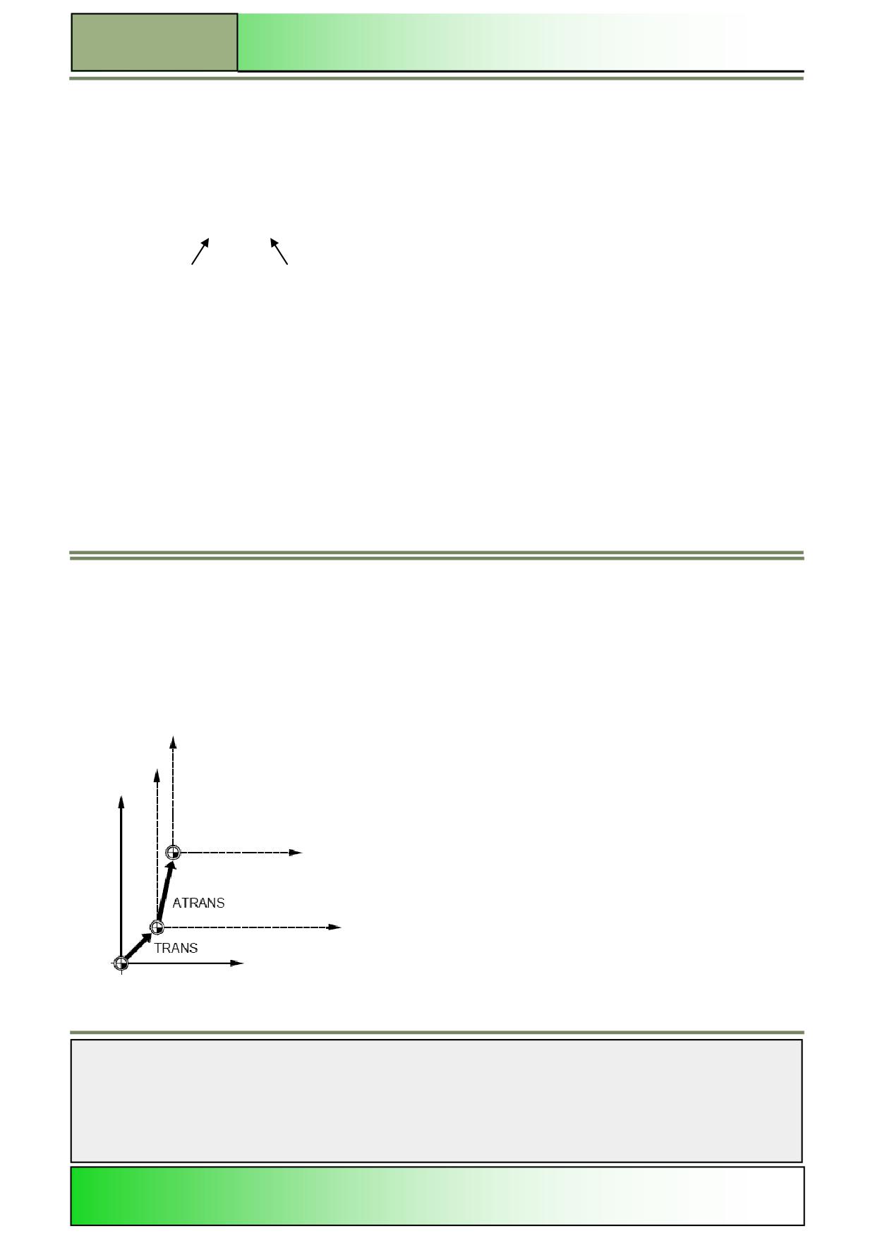
The term “Frame” refers to a calculation rule that permits the coordinate system on the machine to be manipulated.
By means of a programmed instruction the user can, for instance, offset or scale the specified coordinate system.
Example:
N150 TRANS Z-10
Absolute offset
…
N200 ATRANS Z-5
Incremental offset
…
N240 ASCALE X0.5
Scaling of the X-axis
Incremental
Scaling factor for the axis
A = Additive
For the programming of frames the following guidelines apply:
Programmed frames refer always to the last work piece zero point activated in the program, e.g. G54.
The instruction must be included in a single block.
They will be executed in the sequence in which they appear in the program.
Instructions that are not preceded by an “A” (e.g. TRANS Z-10) are replacing Frames, i.e. they clear all other Frame-
instructions used previously in the program.
The preceding “A“ specifies the additive instructions. They enhance all active Frame-instructions used so far in the pro-
gram, in other words, they do not cancel any frame instructions (e.g. ATRANS Z-5).
All frame-instructions are modally active.
To reset active Frames (that is a return to the original work piece zero point) simply program a replacing Frame (e.g.
TRANS ), or “M30” or manually with “RESET”.
Offset of the coordinate system
To permit recurring machining operations to be carried out at various work piece locations, a zero point offset can be pro-
grammed in all the available axes.
X
Z
e.g. G54
Notes
M510
Page 4
828D/840Dsl SINUMERIK Operate
Mirror, offset, rotate, scale for turning
M510
Zero point offset absolute, as referred to the presently valid work piece zero point
Code TRANS [X...] Z…
Programming example: Explanation:
N10 G18 G54
Turning plane G18 and Zero point G54 active
N80 TRANS Z-10
Zero point shifted (offset) to Z-10
N90 G00 X0 Z2
Rapid traverse motion to the now valid
coordinate point X0 and Z2
Zero point offset additive, referred to the presently valid work piece zero point or to possibly previously activated
Frames
Code ATRANS X... Z…
Programming example:
Explanation:
N10 G18 G54
N80 TRANS Z-10
N90 G00 X0 Z2
…
N200 ATRANS Z-5
The point already offset in block N80 is now offset by a further -5 mm in Z
N210 G00 X0 Z2
Rapid traverse motion to the now valid coordinate point X0 and Z2,
N250 TRANS
Cancel all frames, G54 is again active
N260 G00 X200 Z300
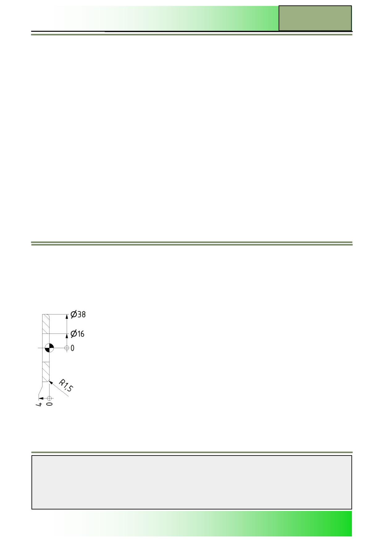
The manufacture of washers from a bar is taken as a programming example. In order to reduce the clamping times, three
washers are to be machined in one setting after which the bar is to be pushed forward and the program repeated.
The protruding part has a blank diameter of 40 mm. The clamping overhang length is to be at least 45 mm. The width of the
parting tool is 3 mm.
Washer 1
The following technology is being employed:
1.
Facing to Z0.1.
2.
Finish turning of the planar face and the diameter 38 with
R1,5.
3.
Drilling the diameter 16 using a core drill.
4.
Parting-off the washer.
5.
Additive offset of the zero point in Z by -8 mm.
6.
Repeat of the whole procedure 2 times.
7.
Resetting the offset and end of program.
8.
Feeding of the bar to an overhang of 45 mm and re-
newed program start.
Notes
828D/840Dsl SINUMERIK Operate
Page 5
M510

M510
Mirror, offset, rotate, scale for turning
The following editor extract shows the lower part of the program.
N160 T10
; Core drill Dia = 16
N170 G97 S2500 F0.15 M4 D1
N180 G00 X0 Z3 M8
N190 G01 Z-7
N200 G00 Z3
N210 G00 X200 Z300
N220 T3
; Parting tool 3.1 wide
N230 G96 S140 F0.1 M4 D2
; Right hand cutting edge activated
N240 G00 X40 Z-4
N250 G01 X14
N260 G00 X40
N270 ATRANS Z-8
; Offset additive
N280 REPEAT LBL14 P2
; Repeat
N290 TRANS
; Cancel the frame
N300 G00 X200 Z300
N310 M30
The offset in block N270 must be additive, since it always refers to itself due to the repeating of the loop.
Scaling of the coordinate system
In certain cases it may be important to alter the scale of the coordinate system.
With this feature geometrically similar shapes of work piece can be programmed in various sizes, e. g. groups of parts or for
mould construction with different contraction allowances.
Scaling of the coordinate system
absolute, as referred to the active
work piece zero point
Code SCALE X… Z…
Here the values of “X” and “Z” are factors by which the coordinate system is to enlarge or diminish.
If the scaling factors are entered differently for each axis a distorted co-ordinate system will result.
Note:
Please note that the turning of tolerance dimensions after the scaling can create difficulties since the tool wear correction
values are not any longer
operative 1:1.
Programming example:
Explanation:
N10 G18 G54
Turning plane G18 and zero point G54
activated,
N20 G00 X200 Z300
N40 SCALE X0.5 Z0.5
The scale is halved for both axes,
N50 G00 X44 Z0
Rapid traverse motion to contour point X44
Z0, ...
Notes
M510
Page 6
828D/840Dsl SINUMERIK Operate
Mirror, offset, rotate, scale for turning
M510
Caution!
Physically the tool moves to X22!!!
Scaling of the coordinate system additive,
as referred to the active work piece zero point,
or to the currently valid coordinate system
selected with Frames
Code ASCALE X… Z…
Programming example:
Explanation:
N10 G18 G54
N20 G00 X200 Z300
N30 TRANS Z-10
Zero point offset to Z-10
N40 ASCALE X0.5 Z0.5
The scale halving in both axes from N30 remains operative
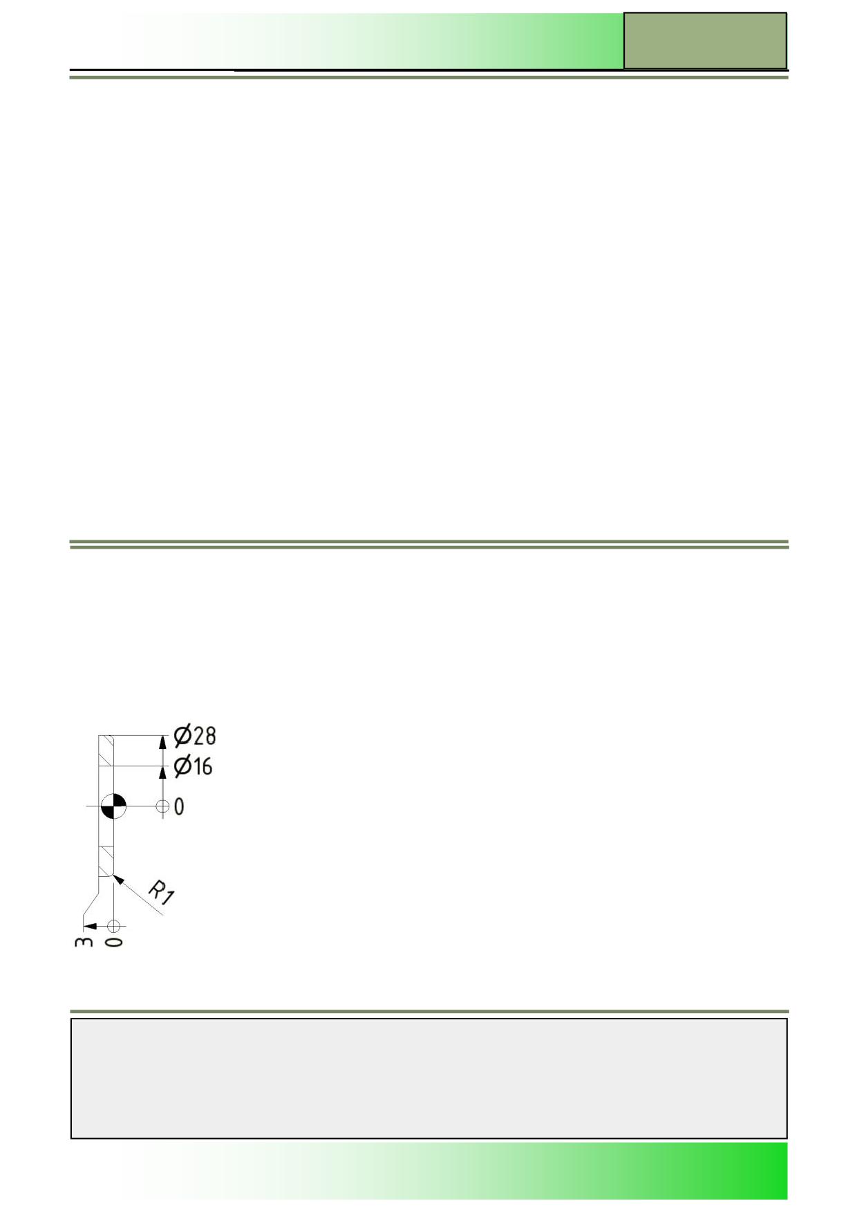
For the explanation of the scaling instruction the machining of similar washers as in section 2 is being used.
These are smaller in both axes. The evaluated scaling factors are 0,737 in diameter and 0,75 for the
Z-axis.
Generally valid formula:
Scaling factor = Dimension after scaling, divided by dimension before scaling 28 / 38 = 0,737
Note:
The blank material is a protruding part with a diameter of 30 mm.
The overhang is to be at least 40 mm. Again the parting tool of width 3 mm is used.
Washer 2
The technology remains the same as for washer 1, only the scal-
ing is added to the program.
Notes
828D/840Dsl SINUMERIK Operate
Page 7
M510

M510
Mirror, offset, rotate, scale for turning
In the editor extract the scaling takes place already before the tool change.
N10 G18 G54 G64 LIMS=4000
N20 SCALE X0.737 Z0.737
; Scaling
N30 LBL14:
N40 G00 X300 Z400
N50 T1
; Roughing tool
N60 G96 S160 F0.2 M4 D1
N70 G00 X44 Z0.2 M8
N80 G01 X-1.6
N90 Z3
N100 G00 G42 X14 Z2
N110 G01 Z0
N120 X38 RND=1.5
N130 Z-8
N140 X42
N150 G00 G40 X200 Z300
Note:
Care must be taken that the tool carrier now no longer traverses to the same physical point as in the unscaled coordinate
system, since the scaling acts in all directions.
The complete program extract is shown in the summary.
Dwell time
If, for example, the chips are to be broken or the tools are to be relieved, a dwell period can be inserted between the blocks.
Dwell time in seconds
Code G04 F…
(“F” is the dwell time conjunction with G04)
Dwell time in revolutions Code G04 S…
(“S” is the number of spindle revolutions in
conjunction with G04 )
To demonstrate the programming of dwell times the already familiar program “WASHER2.MPF” has been extended.
The switch from block N250 to block N270 takes place only after a waiting period of 0,5 sec; the chip breaks.
N210 G00 X200 Z300
N220 T3
; Parting tool 3mm wide
N230 G96 S140 F0.1 M4 D2
; Right hand cutting edge activated
N240 G00 X40 Z-4
N250 G01 X30
N260 G04 F0.5
; Dwell time 0,5 sec
N270 G01 X22
N280 G04 S5
; Dwell time 5 revolutions
N250 G01 X14
N260 G00 X40
Notes
M510
Page 8
828D/840Dsl SINUMERIK Operate

Mirror, offset, rotate, scale for turning
M510
In case of relatively small diameters this time is sufficient for chip breaking. This becomes evident if
the high number of revolutions is compared to the time of dwell.
In the case of large diameters a time-independent switching of blocks may be more advantageous.
If the tool remains stationary at the destination point for a certain number of revolutions the tool relief
can be ascertained.
Note:
The previously programmed values of the addresses “F” for feed and “S” for speed or constant cut-
ting speed remain activated in any case.
Examples
Program for the washer 1
N10 G18 G54 G64 LIMS=4000
N20
;.Without scaling
N30 LBL14:
N40 G00 X200 Z300
N50 T1
; Roughing tool
N60 G96 S160 F0.2 M4 D1
N70 G00 X42 Z0.1 M8
N80 G01 X-1.6
N90 Z3
N100 G00 G42 X14 Z2
N110 G01 Z0
N120 X38 RND=1.5
N130 Z-8
N140 X42
N150 G00 G40 X200 Z300
N160 T10
; Core drill Ø16mm
N170 G97 S2500 F0.15 M4 D1
N180 G00 X0 Z3 M8
N190 G01 Z-7
N200 G00 Z3
N210 G00 X200 Z300
N220 T3
; Parting tool 3mm wide
N230 G96 S140 F0.1 M4 D2
; Right hand cutting edge activated
N240 G00 X40 Z-4
N250 G01 X14
N260 G00 X40
N270 ATRANS Z-8
; Additive offset
N280 REPEAT LBL14 P2
; Repeat
N290 TRANS
; Cancel all Frames
N300 G00 X200 Z300
N310 M30
Notes
828D/840Dsl SINUMERIK Operate
Page 9
M510

M510
Mirror, offset, rotate, scale for turning
Program for the washer 2
N10 G18 G54 G64 LIMS=4000
N20 SCALE X0.737 Z0.737
; Scaling
N30 LBL14:
N40 G00 X300 Z400
N50 T1
; Roughing tool
N60 G96 S160 F0.2 M4 D1
N70 G00 X44 Z0.2 M8
N80 G01 X-1.6
N90 Z3
N100 G00 G42 X14 Z2
N110 G01 Z0
N120 X38 RND=1.5
N130 Z-8
N140 X42
N150 G00 G40 X200 Z300
N160 T10
; Core drill Ø16mm
N170 G97 S2500 F0.15 M4 D1
N180 G00 X0 Z3 M8
N190 G01 Z-7
N200 G00 Z3
N210 G00 X200 Z300
N220 T3
; Parting tool 3mm wide
N230 G96 S140 F0.1 M4 D2
; Right hand cutting edge activated
N240 G00 X40 Z-4
N250 G01 X14
N260 G00 X40
N270 ATRANS Z-8
; Offset additive
N280 REPEAT LBL14 P2
; Repeat
N290 TRANS
; Cancel all Frames
N300 G00 X200 Z300
N310 M30
Notes
M510
Page 10
828D/840Dsl SINUMERIK Operate