SINUMERIK 840D sl. Training. Operate - Turning (2016-2020) - page 22
M601
Basics of programming with ShopTurn
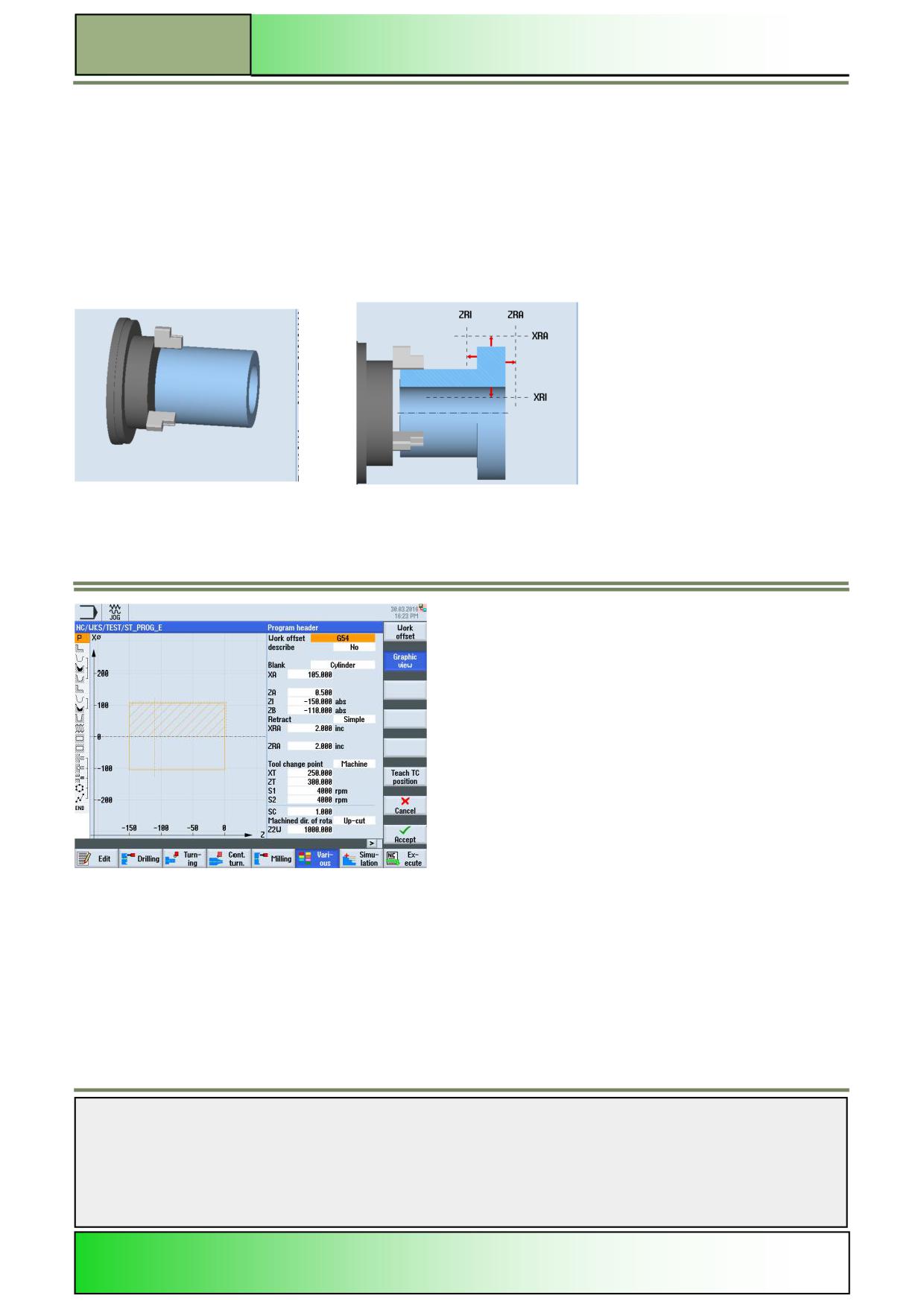
Changing the “Graphic view” on the blank
The graphical view on the blank can be changed in the operating area “Program” within the functions “Edit”, “Drilling”,
“Turning”, “Contour turning” “Milling”, “Various” and “Straight Circle”.
Note:
The help pictures with the corresponding animation are only shown when the VSK 2 “Graphic view” is deselected.
The view on the blank can be changed as follows:
1.
In the operating area “Program” within the operating mode “JOG, “MDA, or “AUTO” press the HSK 1.6
“Various”.
2.
Activate or deactivate the VSK 2 “Graphic view” to switch the view in the parameter window between:
3-D view or help picture with animation or
Programming graphic (outline graphic).
Notes
M601
Page 24
828D/840Dsl SINUMERIK Operate

Basics of programming with ShopTurn
M601
Changing the program settings
1.
In the operating area “Program”, within the operating mode “JOG, “MDA, or “AUTO”, press the
HSK 1.6 “Various”.
2.
Press the VSK 1 “Settings”.
The window for the “Settings” opens.
3.
If desired, change the graphic view in the parameter window by pressing the VSK 2 “Graphic
view”.
4.
Enter the parameters for retract, tool change point, safety distance, speed limits or machining
sense.
5.
Confirm your inputs by pressing the VSK 8 “Accept” or abort by pressing the VSK 7 “Cancel”.
A new program block “Settings” is inserted into the work plan (see picture below).
Transformations
To make programming easier, you can transform the coordinate
system.
Use this function, for example, to rotate the coordinate system.
Coordinate transformations only apply in the current program.
You can define displacement, rotation, scaling or mirroring.
You can select between a new or an additive coordinate transformation.
In the case of a new coordinate transformation, all previously defined
coordinate transformations are deselected.
An additive coordinate transformation acts in addition to the currently selected coordinate transformations.
Supported are:
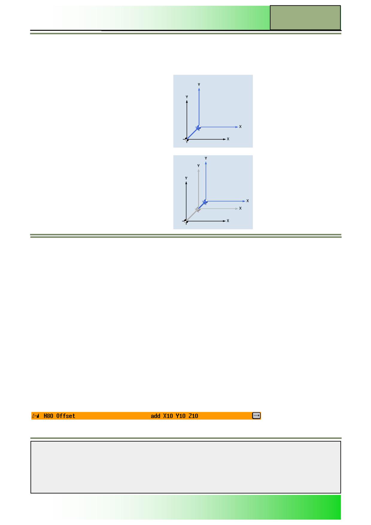
Offset:
For each axis, you can program an offset of the zero point.
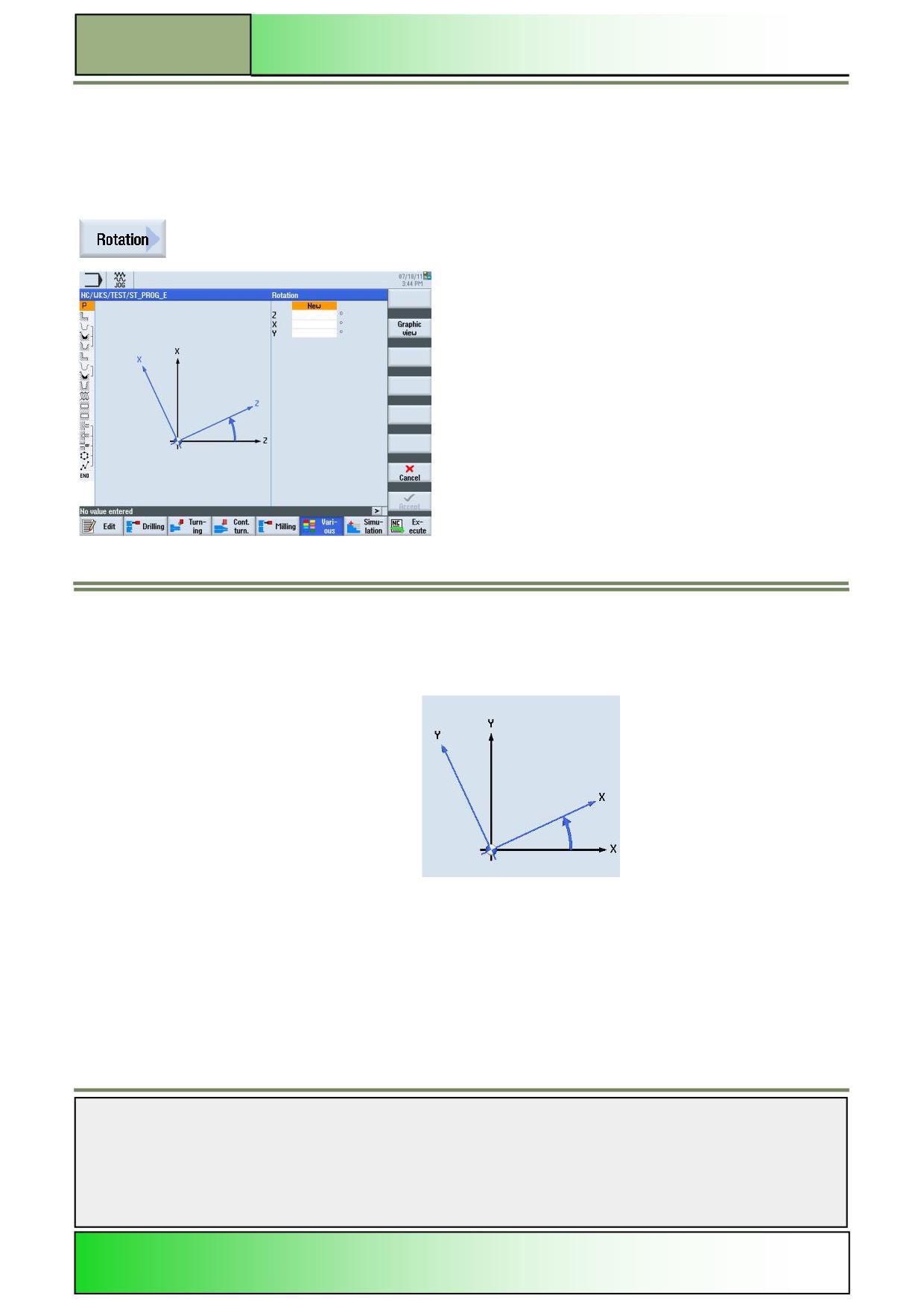
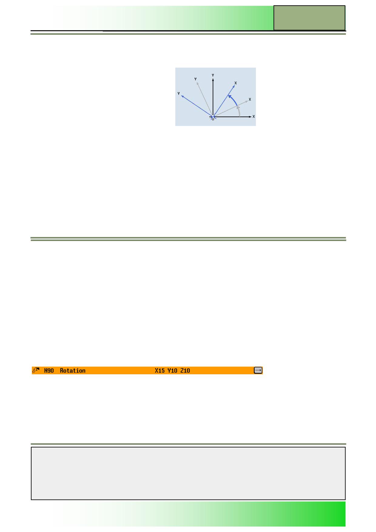
Rotation:
You can rotate every axis through a specific angle. A positive angle corresponds to a counter-clockwise rotation.
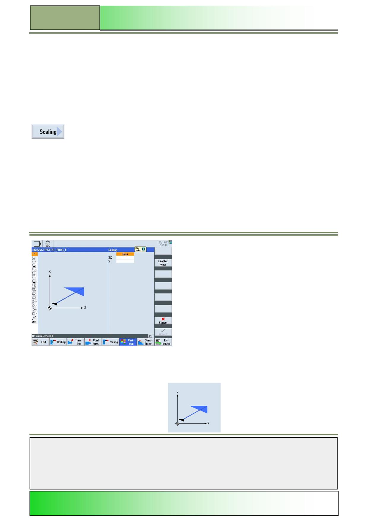
Scaling:
You can specify a scale factor for the active machining plane as well as for the tool axis. The programmed coordinates
are then multiplied by this factor. Note that the scaling always refers to the zero point of the workpiece. For example, if
you increase the size of a pocket whose centre point does not coincide with the zero point, scaling will shift the centre
of the pocket.
Mirroring:
Furthermore, you can mirror all axes. Enter the axis to be mirrored in each case. Note that with mirroring, the travel
direction of the cutting tool (conventional/climb) is also mirrored.
Notes
828D/840Dsl SINUMERIK Operate
Page 25
M601
M601
Basics of programming with ShopTurn
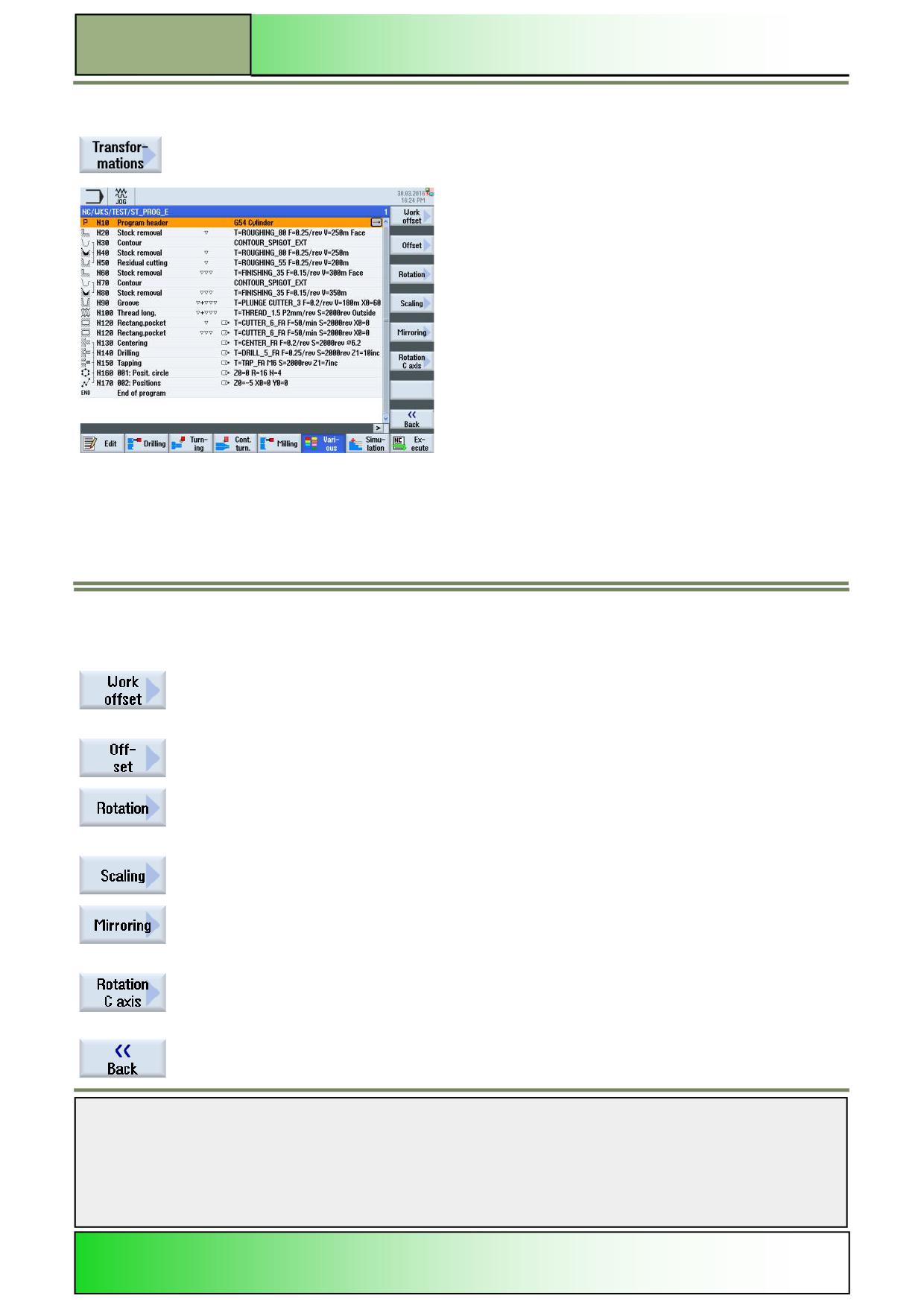
Selecting the function „Transformations“
By pressing the VSK 5 “Transformations“ the following vertical softkey bar in the editor window
opens.
Vertical softkey bar
Display area
Description
By pressing the VSK 1 “Work offset” the parameter window for the work offset opens.
By pressing the VSK 2 “Offset” the parameter window for the offset opens.
By pressing the VSK 3 “Rotation” the parameter window for the rotations opens.
By pressing the VSK 4 “Scaling” the parameter window for the scaling opens.
By pressing the VSK 5 “Mirroring” the parameter window for the mirroring opens.
By pressing the VSK 6 “Rotation C axis” the parameter window for the rotation of the C axis
opens.
By pressing the VSK 8 “Back” you switch back to the main screen of the function “Various”.
Notes
M601
Page 26
828D/840Dsl SINUMERIK Operate
Basics of programming with ShopTurn
M601
Work offset
You can call work offsets (G54, etc.) from any program.
You can use these offsets, for example, when you want to machine
workpieces with various blank dimensions using the same program.
The offset will, in this case, adapt the workpiece zero to the new blank.
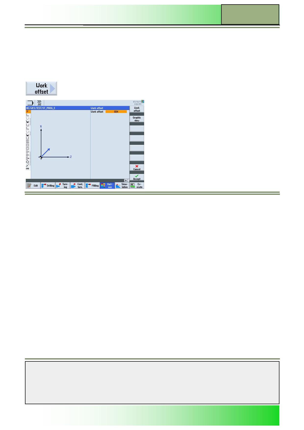
Selecting the function “Work offset”
By pressing the VSK 1 “Work offset” the input mask “work offset” opens.
Parameters for the work offset
Parameter
Meaning
Work offset.
Alternative work offsets
Basic
Reference G500
Basic ref.
G54
Storable
Zero offset
Storable
Zero offset
G55
Storable
Zero offset
G56
Storable
Zero offset
G57
Notes
828D/840Dsl SINUMERIK Operate
Page 27
M601
M601
Basics of programming with ShopTurn
Setting the work offset
1.
In the operating area “Program“ and operation mode “JOG”, “MDA”, or “AUTO” press the HSK 6
“Various“ and the VSK5 “Transformations”.
2.
Press the VSK 1 “Work offset”.
3.
Optionally change the graphic view for the blank between sectional drawing/3-D model or
wireframe model by pressing the VSK 2 “Graphic view”.
4.
Select the work offset (Basic reference, G54, G55, G56 or G57).
Press the VSK 8 “Accept” to confirm your selection or press the VSK 7 “Cancel” to abort.
A new program block “Work offset” is inserted into the program in the editor window (see picture
below).
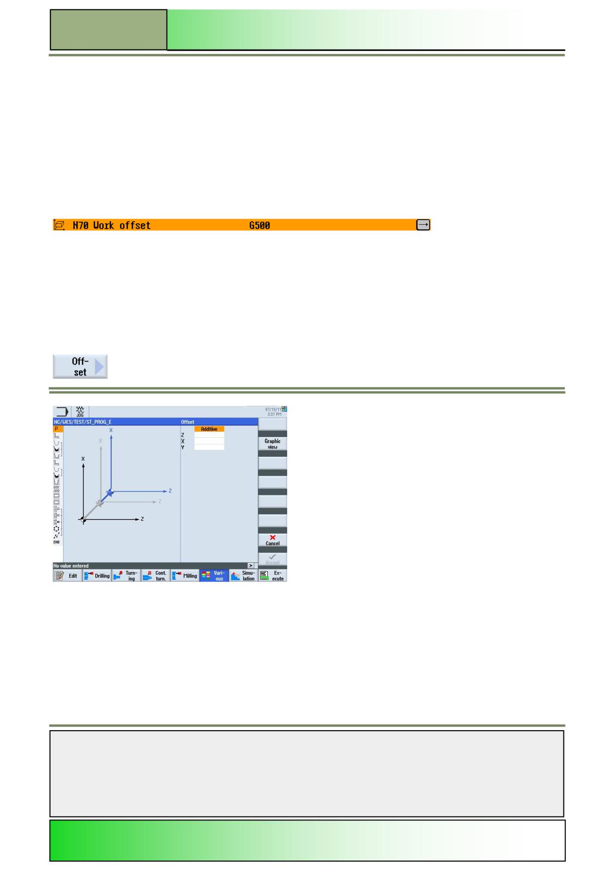
Offset
Offsets apply only to the current program.
Besides, you can select between a new and an additive offset.
With a new offset, all offsets defined before are deselected.
An additive offset works additional to the current selected offset.
For every axis an offset can be programmed.
Selecting the function “Offset”
By pressing the VSK 2 “Offset” the input screen mask ”Offset” opens.
Notes
M601
Page 28
828D/840Dsl SINUMERIK Operate
Basics of programming with ShopTurn
M601
Parameters for the “Offset”
Parameters
Description
Help picture/Animation
Offset:
Adds a new offset
New
Adds an additive offset
Additive
Axes:
Unit
X
Offset X-axis
mm
Offset Y-axis
mm
Y
Offset Z-axis
mm
Z
Setting the “Offset”
1.
In the operating area “Program“ and operation mode “JOG”, “MDA”, or “AUTO” press the HSK
6 “Various“ and the VSK5 “Transformations”.
2.
Press the VSK 2 “Offset”.
3.
Optionally change the graphic view for the blank between sectional drawing/3-D model or
wireframe model by pressing the VSK 2 “Graphic view”.
4.
Select the kind of offset “new” or “additive”.
Enter the offset values for the different axes (X,Y,Z) in millimetre.
Press the VSK 8 “Accept” to confirm your inputs or press the VSK 7 “Cancel” to abort.
A new program block “Offset” is inserted into the program in the editor window (see picture
below).
Notes
828D/840Dsl SINUMERIK Operate
Page 29
M601
M601
Basics of programming with ShopTurn
Rotation
Rotations apply only to the current program. Besides, you can select between a new and an additive rotation. With a new
rotation, all rotations defined before are deselected. An additive rotation works additional to the current selected rotation.
For every axis an rotational angle in degrees can be programmed. A positive angle means a rotation counter clockwise.
Selecting the function “Rotation“
By pressing the VSK 3 “Rotation“ the input screen mask “Rotation” opens.
Parameters for “Rotation”
Parameters
Description
Help picture/Animation
Rotation:
Adds a new rotation
New
Notes
M601
Page 30
828D/840Dsl SINUMERIK Operate
Basics of programming with ShopTurn
M601
Parameter
Description
Help picture/Animation (continuation)
Rotation:
Incremental rotation
Additive
Axes:
Units
Rotation around the
mm
X
X-axis
Y
Rotation around the
mm
Y- axis
Rotation around the
mm
Z
Z-axis
Setting the rotations
1.
In the operating area “Program“ and operation mode “JOG”, “MDA”, or “AUTO” press the HSK
6 “Various“ and the VSK5 “Transformations”.
2.
Press the VSK 3 “Rotation“.
3.
Optionally change the graphic view for the blank between sectional drawing/3-D model or
wireframe model by pressing the VSK 2 “Graphic view”.
4.
Select if you want to add a “new” or a “additive” rotation. Enter the values for the rotation
about the axes X, Y, und Z in degrees.
Press the VSK 8 “Accept” to confirm your inputs or press the VSK 7 “Cancel” to abort.
A new program block “Rotation” is inserted into the program in the editor window (see picture
below).
Notes
828D/840Dsl SINUMERIK Operate
Page 31
M601
M601
Basics of programming with ShopTurn
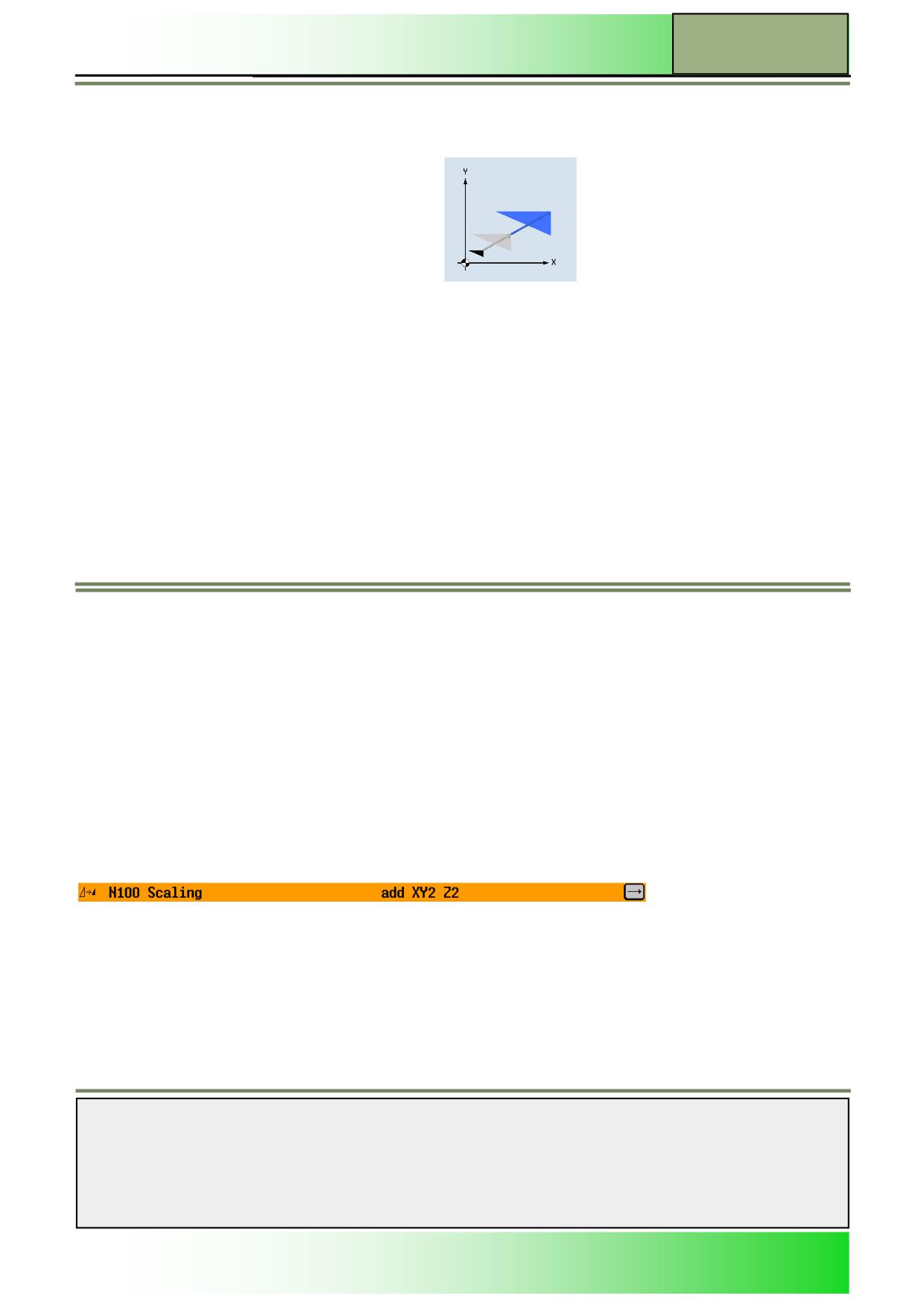
Scaling
Scaling applies only to the current program. Besides, you can select between a new and an additive scaling.
With a new scaling, every scaling defined so far is deselected.
An additive scaling works incremental to the current selected scaling.
You can specify a scale factor for the active machining plane as well as for the tool axis. The programme coordinates are
then multiplied by this factor.
Note:
Note that the scaling always refer to the zero point of the workpiece.
For example, if you increase the size of a pocket whose centre point does not coincide with the zero point, scaling will shift
the centre of the pocket.
5.4.6.1 Selecting the function “Scaling”
By pressing the VSK 4 “Scaling” the input screen mask “Scaling” opens.
5.4.2 Parameters for “Scaling”
Parameter
Description
Help picture/Animation
Scaling:
New
Adds a new scaling
Notes
M601
Page 32
828D/840Dsl SINUMERIK Operate
Basics of programming with ShopTurn
M601
Parameter
Description
Help picture/Animation (continuation)
Scaling:
Adds an additive scaling
Additive
Axes:
Scaling factor XY
XY
Scaling factor Z
Z
Setting the scaling
1.
In the operating area “Program“ and operation mode “JOG”, “MDA”, or “AUTO” press the HSK
6 “Various“ and the VSK5 “Transformations”.
2.
Press the VSK 4 „Scaling“.
3.
Optionally change the graphic view for the blank between sectional drawing/3-D model or
wireframe model by pressing the VSK 2 “Graphic view”.
4.
Select whether the scaling “new” or “additive”.
Insert the values for the scaling factor XY and Z.
Press the VSK 8 “Accept” to confirm your inputs or press the VSK 7 “Cancel” to abort.
A new program block “Rotation” is inserted into the program in the editor window (see picture
below).
Notes
828D/840Dsl SINUMERIK Operate
Page 33
M601
M601
Basics of programming with ShopTurn
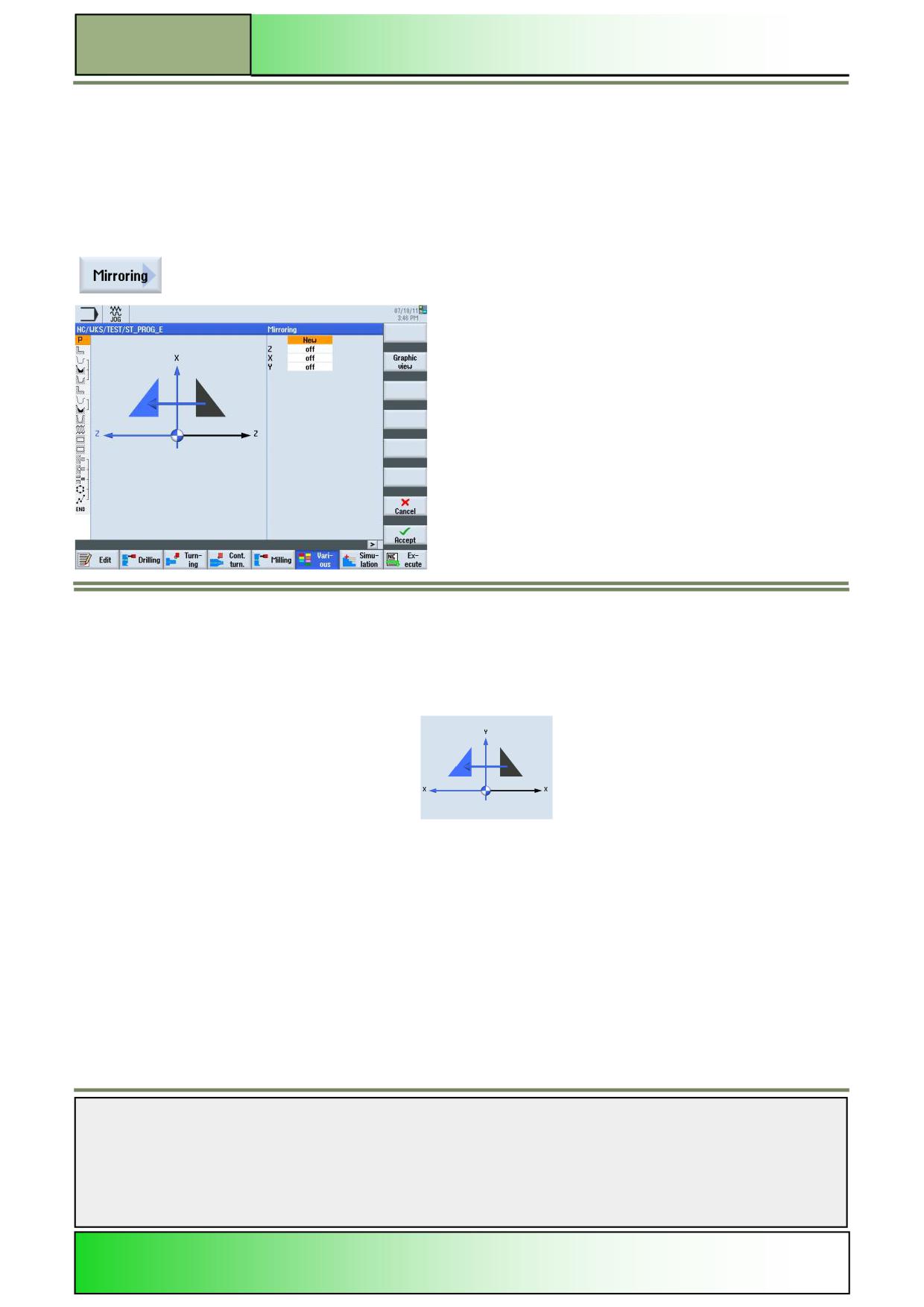
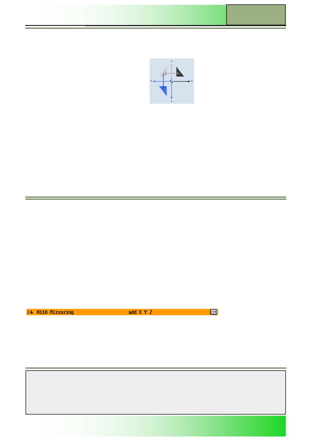
Mirroring: applies only to the current program. Besides, you can select between a new and an additive mirroring. With a
new mirroring, all mirror images defined so far are deselected. An additive mirroring works additional to the current selected
mirroring. Furthermore it is possible to mirror all axes.
Activate the axis to be mirrored in each case.
Note:
Note that with mirroring, the travel direction of the cutting tool (down-cut/up-cut) is also mirrored.
Selecting the function “Mirroring”
By pressing the VSK 5 “Mirroring” the input screen mask “Mirroring” opens.
Parameters for “Mirroring”
Parameter
Description
Help picture/Animation
Mirroring:
Adds a new mirroring
New
Notes
M601
Page 34
828D/840Dsl SINUMERIK Operate
Basics of programming with ShopTurn
M601
Parameters
Description
Help picture/animation
(continuation)
Mirroring:
Additive
Adds an additive mirroring
Axes:
Mirroring for the X-axis (on/
X
off)
Y
Mirroring for the Y-axis (on/
off)
Mirroring for the Z-axis (on/
Z
off)
Mirroring the axes
1.
In the operating area “Program“ and operation mode “JOG”, “MDA”, or “AUTO” press the HSK
6 “Various“ and the VSK5 “Transformations”.
2.
Press the VSK 5 “Mirroring”.
3.
Optionally change the graphic view for the blank between sectional drawing/3-D model or
wireframe model by pressing the VSK 2 “Graphic view”.
4.
Select whether the Mirroring is “new” or “additive”.
Switch on or off the axis that you want to have mirrored.
Press the VSK 8 “Accept” to confirm your inputs or press the VSK 7 “Cancel” to abort.
A new program block “Mirroring” is inserted into the program in the editor window (see picture
below).
Notes
828D/840Dsl SINUMERIK Operate
Page 35
M601
M601
Basics of programming with ShopTurn
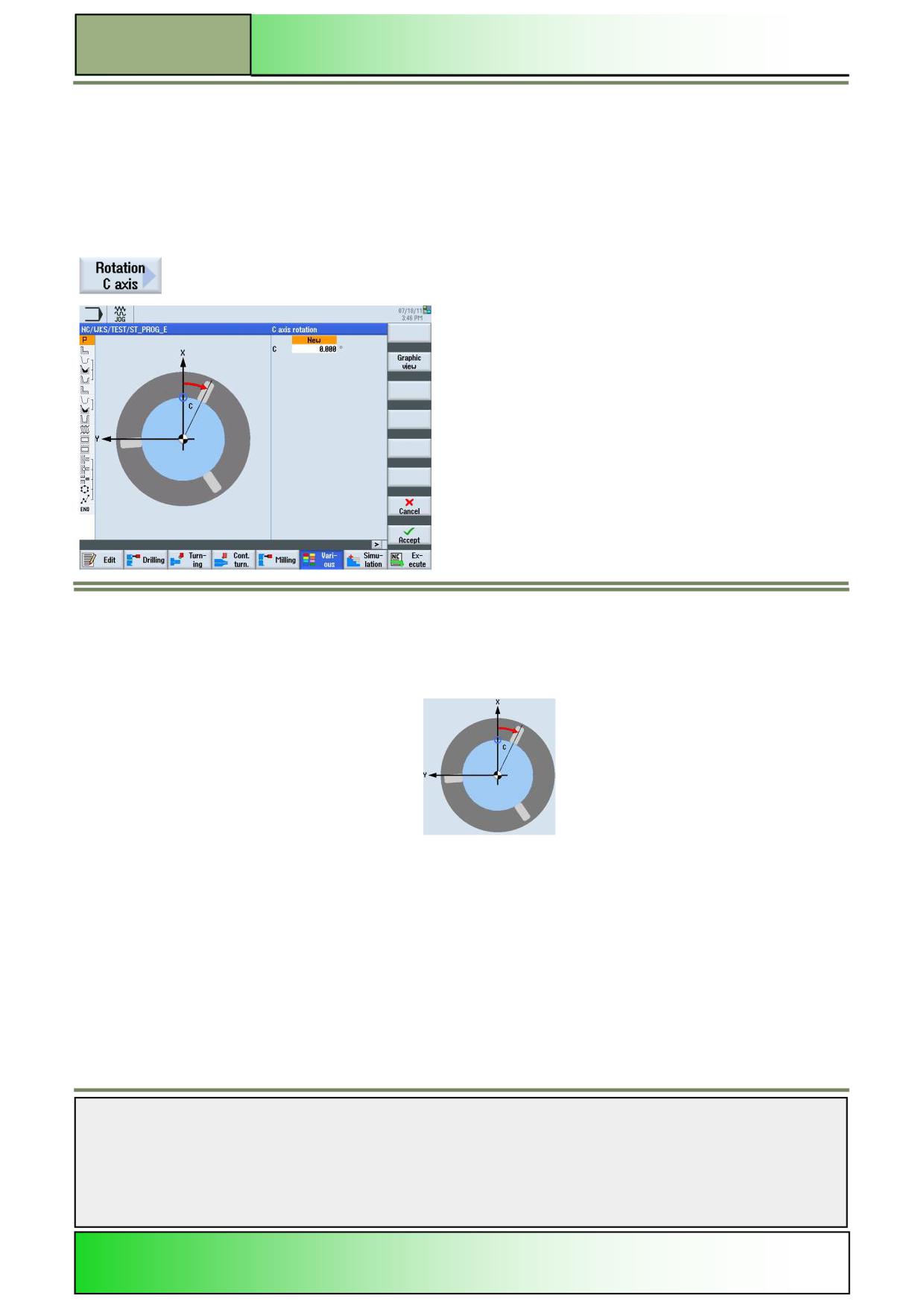
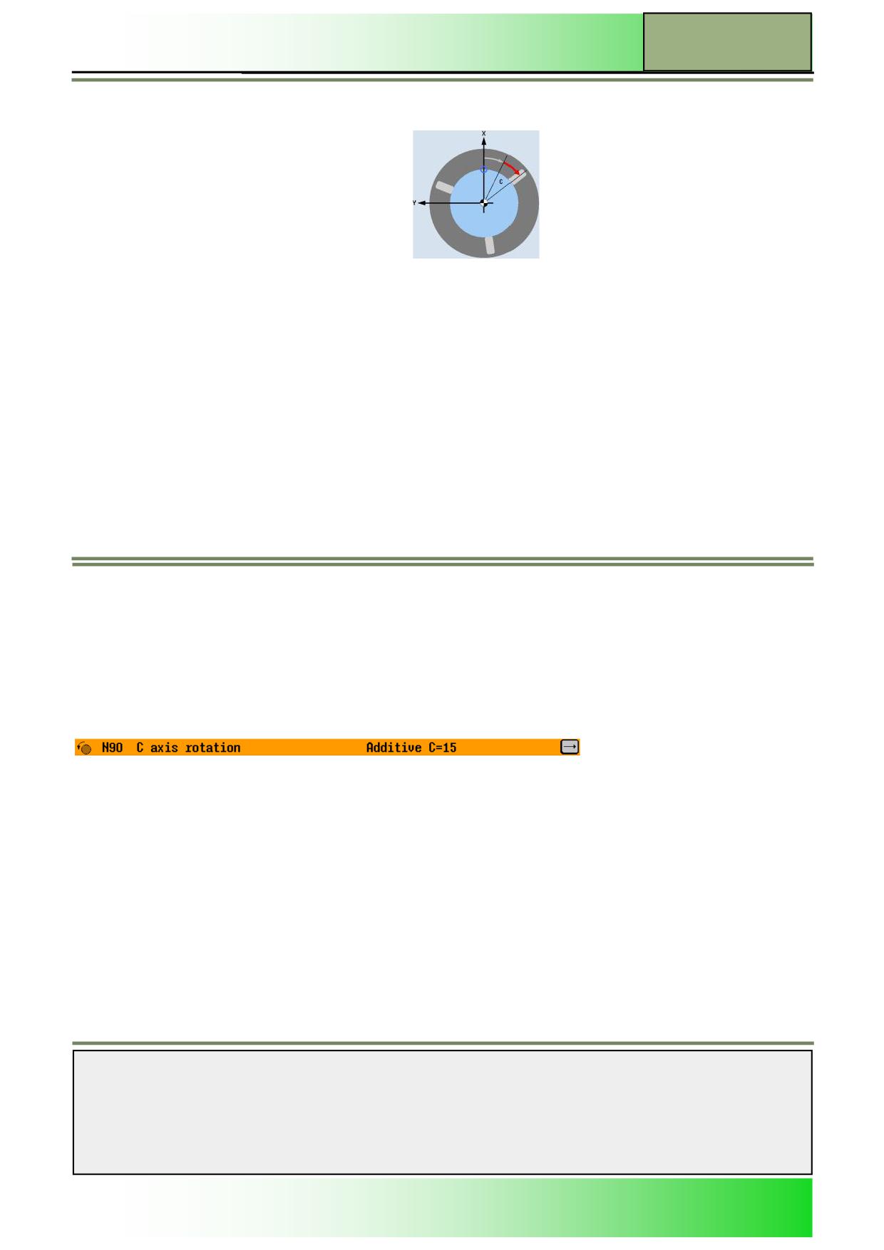
Rotating the C axis
Rotations of the C axis apply only in the current program. Besides, you can select between a new and an additive rotation.
With a new rotation of the C axis, all rotations of the C axis defined so far are deselected. An additive rotation works addi-
tional to the current selected rotations.
You can turn the C axis through a specific angle to enable subsequent machining operations to be performed at a particular
position on the end face or peripheral surface. The direction of rotation is set in a machine data. Enter the value for the rota-
tion of the C axis in degree.
Selecting the function “Rotation C axis”
By pressing the VSK 6 “Rotation C axis” the input mask for the parameters “C axis rotation”
opens.
Parameters for „Rotation C axis“
Parameters
Description
Help picture/animation
Rotation:
New rotation
New
Notes
M601
Page 36
828D/840Dsl SINUMERIK Operate
Basics of programming with ShopTurn
M601
Parameters
Description
Help picture/animation
(continuation)
Additive
Additive rotation
Rotation C:
C axis rotation in degree
C
Setting the rotation of the C axis
1.
In the operating area “Program” press the HSK 1.6 “Various” and the VSK 5 “Transformations”.
2.
Press the VSK 6 “Rotation C axis”.
The input mask “Rotation C axis” for the parameter input opens.
3.
Optionally change the graphic view of the help screen by pressing the VSK 2 “Graphic view”.
4.
Select whether the rotation of the C axis is new or additive.
5.
Enter a value for the C axis rotation in degree.
Confirm your inputs by pressing the VSK 8 “Accept” or abort by pressing the VSK 7 “Cancel”.
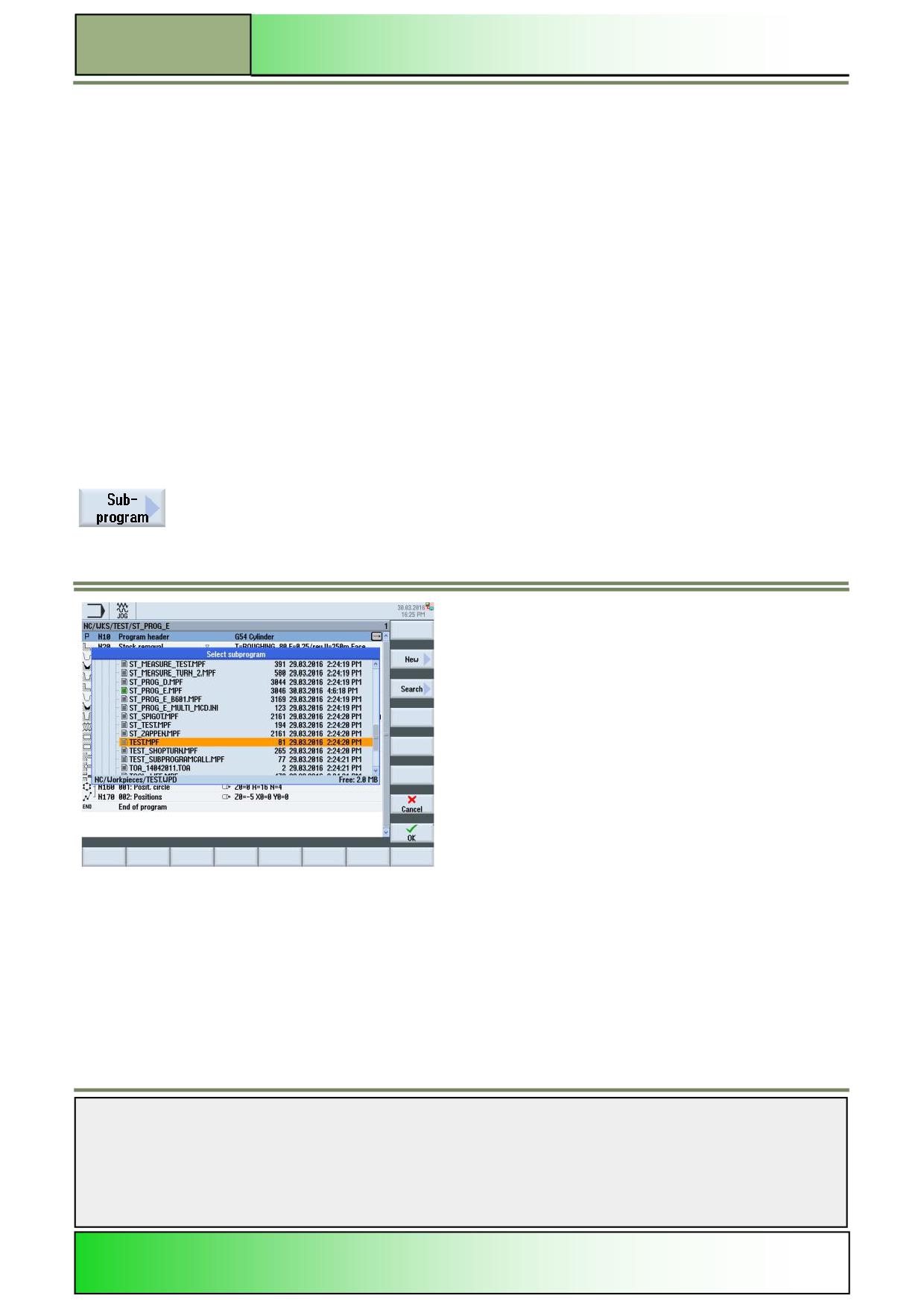
A new sequential program block “Rotation C axis” is inserted into the work plan (see picture
below).
Notes
828D/840Dsl SINUMERIK Operate
Page 37
M601
M601
Basics of programming with ShopTurn
Subprograms
If you require the same machining steps in the programming of different workpieces, you can define these machining steps
in a separate subroutine. You can then call this subroutine in any program.
Identical machining steps therefore only have to be programmed once. ShopTurn does not differentiate between main pro-
gram and subprogram. This means that you can call a "standard" sequential program or G code program as subprograms in
another sequential program. In this subprogram, you can also call another subprogram. The maximum nesting depth is 8
subroutines. You cannot insert subroutines among blocks chained by the control. If you want to call a sequential ShopTurn
program as a subroutine, the program must already have been calculated once (load or simulate
program in “AUTO” operating mode). This is not necessary for G code subroutines.
The subroutine must always be stored in the NCK main memory (in a separate directory "XYZ" or in the "ShopTurn", "Part
programs", "Subprograms" directories). If you want to call a subprogram located on another drive, you can use the G code
command "EXTCALL".
Note:
Please note that, when a subprogram is called, ShopTurn evaluates the
settings in the program header of the subroutine. These settings also
remain active even after the subprogram has ended.
If you wish to activate the settings from the program header for the main program again, you can make the settings again in
the main program after calling the subprogram.
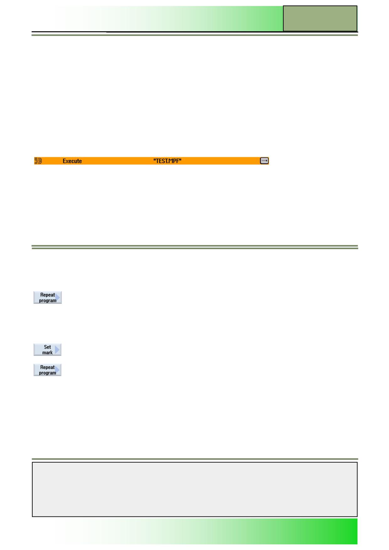
Selecting the function “Subprogram“
By pressing the VSK 6 “Subprogram” the input mask for selecting a “Subprogram” opens.
Notes
M601
Page 38
828D/840Dsl SINUMERIK Operate
Basics of programming with ShopTurn
M601
Subprogram call
1.
In the operating area “Program” press the HSK 1.6 “Various”.
2.
Press the VSK 1.6 “Subprogram”.
The input mask for selecting a “Subprogram” opens.
3.
Optionally change the graphic view of the help screen by pressing the VSK 2 “Graphic view”.
4.
Enter the path to the subprogram file into the “Path/workpiece” input field and the name of the
subprogram into the “Program name” input field.
Confirm your inputs by pressing the VSK 8 “Accept” or abort by pressing the VSK 7 “Cancel”.
A new sequential program block “Execute” with the subprogram path and name is inserted into
the work plan (see picture below).
Repeating program blocks
If certain steps in the machining of a workpiece have to be executed more than once, it is only necessary to program these
steps once.
ShopTurn offers a function for repeating program blocks.
You must enclose the program blocks that you want to repeat with a start and end marker. You can
then call these program blocks up to 9999 times again within a program. The markers must be unique, i.e. they must have
different names. No names used in the NCK can be used for this.
You can also set markers and repeats after creating the program, but not within chained program blocks.
Note:
It is also possible to use the same marker as the end marker of the preceding program blocks and as the start marker for
the following program blocks.
Selecting the function “Repeat program”
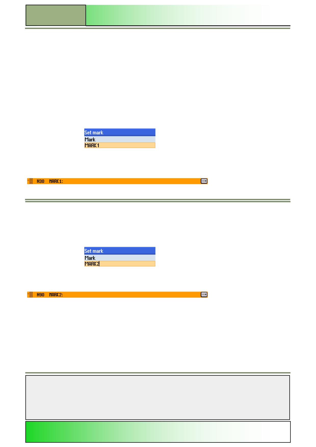
By pressing the VSK 3 “Repeat program” the vertical softkey bar with functions for repeating a
program opens.
Vertical softkey bar
Display area
Description
By pressing the VSK 1 “Set Mark” the window for setting a start or end mark opens.
By pressing the VSK 2 “Repeat program” an input mask opens where you can specify the start
and end marker which enclose the program parts you want to repeat.
Notes
828D/840Dsl SINUMERIK Operate
Page 39
M601
M601
Basics of programming with ShopTurn
Repeating program blocks in the program
1.
In the operating area “Program” press the HSK 1.6 “Various”.
2.
Press the VSK 1.8 “Extend” to open the vertical softkey bar 2.
3.
Press the VSK 2.3 “Repeat program”.
4.
Place the orange selection cursor on the program block before the program block that you want
to repeat.
5.
Press the VSK 1 “Set Mark” to insert a start mark.
In the “Set mark” input window, enter an individual name for the start mark (see the following
picture).
With pressing the VSK 8 “Accept” a new sequential program block “MARK1”will be inserted into
the work plan (see picture below).
6.
Place the orange selection cursor on that program block in the work plan that shall be the last
block in the repetition sequence.
7.
Press the VSK 1 “Set mark” to insert a stop mark.
In the “Set mark” input window, enter an individual name for the end mark (see the following pic-
ture).
With pressing the VSK 8 “Accept” a new sequential program block “MARK2” will be inserted into
the work plan (see picture below).
Notes
M601
Page 40
828D/840Dsl SINUMERIK Operate
Basics of programming with ShopTurn
M601
8.
Place the orange selection cursor on that block,
after which you want to repeat the program sequence.
9.
Press the VSK 2 “Repeat program”.
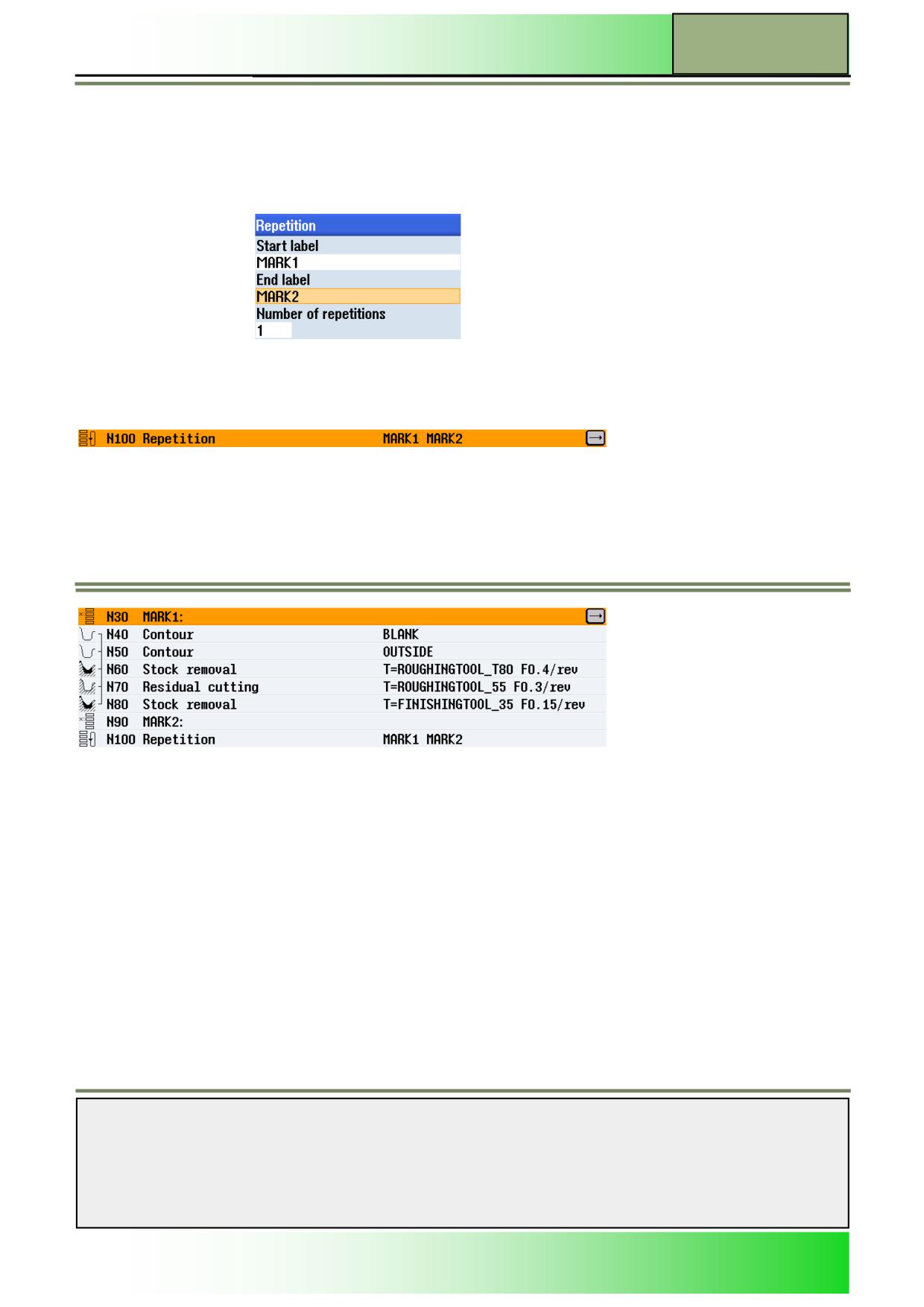
In the input mask “Repetition” enter the name for the start mark and the end mark, as well as
the number of repetitions.
Confirm your inputs by pressing the VSK 8 “Accept”
A new sequential program block “Repetition MARK1 MARK2” is inserted into the work plan
(see picture below).
10.
The program blocks between the marks (MARK1, MARK2) will be repeated as often as entered
in the “Number of repetitions” field.
Notes
828D/840Dsl SINUMERIK Operate
Page 41
M601

M601
Basics of programming with ShopTurn
ShopTurn provides various extensive and detailed simulation functions for displaying the simulation of the programmed
workpiece.
During simulation, the current program is calculated in its complete form and the result is displayed in 3D graphic form.
You can select the following modes of representation for simulation:
Side view
3D
2 windows
The simulation uses the correct proportions for the tools and workpiece contours.
The traverse paths for the tools are shown in colour:
Red line = tool is moving at rapid traverse
Green line = tool is moving at machining feedrate
In all views, a clock is displayed during graphical processing. The
displayed machining time (in hours/minutes/seconds) indicates the approximate time that would actually be required to exe-
cute the machining program on the machine (incl. tool change).
If a program is interrupted during simultaneous recording, the clock stops.
In addition, the current axis coordinates, the override, and the program block currently being executed are also displayed.
The active tool with the cutting edge number and feedrate are also displayed in the simulation.
Transformations are displayed differently during simulation and
simultaneous recording:
Coordinate transformations (translation, scaling, …) are displayed as programmed.
Cylinder surface transformations are displayed as a developed surface.
After swivel transformation, the previous machining operations are deleted from the display and only machining of the
swivelled plane is displayed (viewing angle perpendicular to the swivelled plane).
Zero offsets (G54, etc.) do not alter the zero in the graphical display. This means that, in the case of multiple clampings,
the machining operations for each of the individual workpieces are plotted on top of one another.
Note:
If you want to display a different portion of the workpiece from the one defined in ShopTurn, you can define a new blank in
the program.
Notes
M601
Page 42
828D/840Dsl SINUMERIK Operate
Basics of programming with ShopTurn
M601
Simulation
Selecting the function “Simulation”
The function “Simulation” can be selected from the operating mode “JOG“, “MDA“ and “AUTO“ as follows:
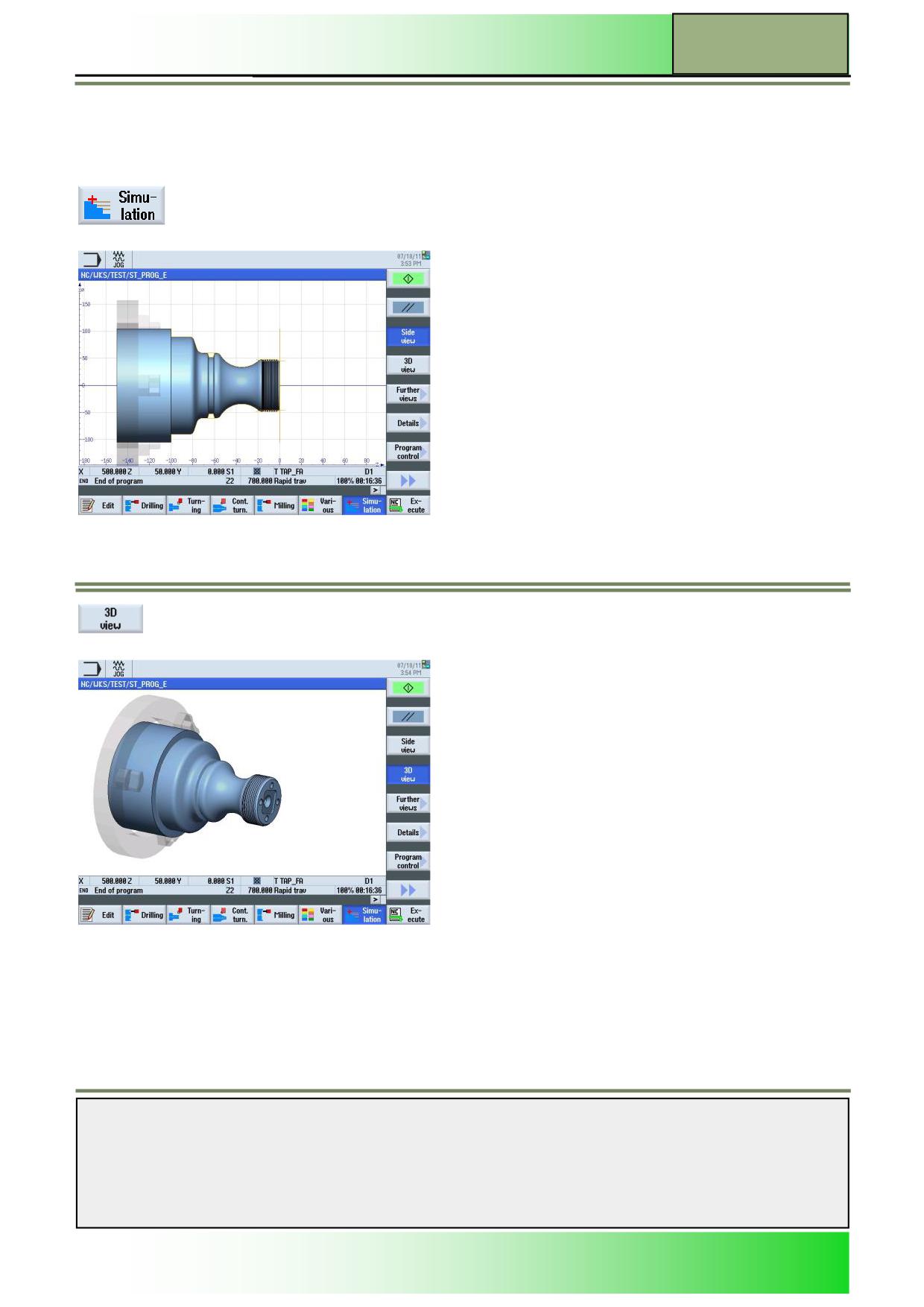
With a program loaded, press the HSK 1.7 “Simulation“ to start a simulation run.
The following screen opens, with a side view on the blank by default.
By pressing the VSK 1.4 “3D view”, the simulation of the workpiece is shown from the face
view (see picture below).
The following functions are available in the vertical softkey bar.
Notes
828D/840Dsl SINUMERIK Operate
Page 43
M601
M601
Basics of programming with ShopTurn
Vertical softkey bar 1 and 2
Display area
Description
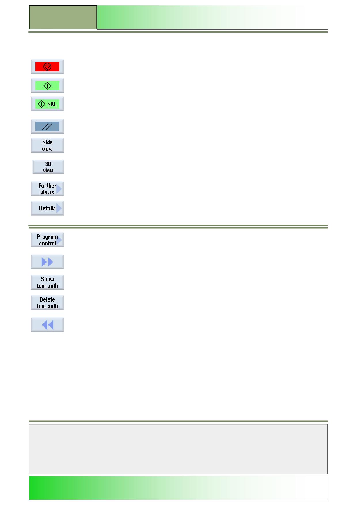
By pressing the VSK 1.1 “Stop“ the simulation will be halted. The softkey will be replaced with
the “Start” softkey, in order to continue the simulation again.
By pressing the VSK 1.1 “Start” the simulation will be started or continued. The softkey will be
replaced with the “Stop” softkey (see VSK 1.1 “Stop”).
By pressing the VSK 1.1 “SBL“ the simulation will be processed block by block. This softkey
replaces the softkey “Start”, if the VSK 4 “Single block” is activated under the function “Program
control”.
By pressing the VSK 1.2 “Reset“ the simulation will be aborted.
The VSK 1.3 “Side view” is activated by default and shows the simulation in from the side.
By pressing the VSK 1.4 “3D view” the simulation of the workpiece will be shown from the front.
By pressing the VSK 1.5 “Further views” the vertical softkey bar opens, with more options to
adjust the view on the simulation process.
By pressing the VSK 1.6 “Details“ the vertical softkey bar opens, where you can adjust the level
of details that will be shown during the simulation.
By pressing the VSK 1.7 “Program control” the vertical softkey bar opens, with functions to con-
trol the simulation run.
By pressing the VSK 1.8 “Extend” the vertical softkey bar 2 with the following functions will be
displayed.
By pressing the VSK 2.3 “Show tool path” the display of the simulated tool path can be
switched on and off.
By pressing the VSK 2.4 “Delete tool path” the animated tool path in the simulation window will
be deleted. A new tool path is shown immediately after pressing this softkey or after running a
new simulation (if the simulation is in “Stop”- or “Reset”- mode).
By pressing the VSK 2.8 “Back” you switch back to the vertical softkey bar 1.
Notes
M601
Page 44
828D/840Dsl SINUMERIK Operate
Basics of programming with ShopTurn
M601
Further views
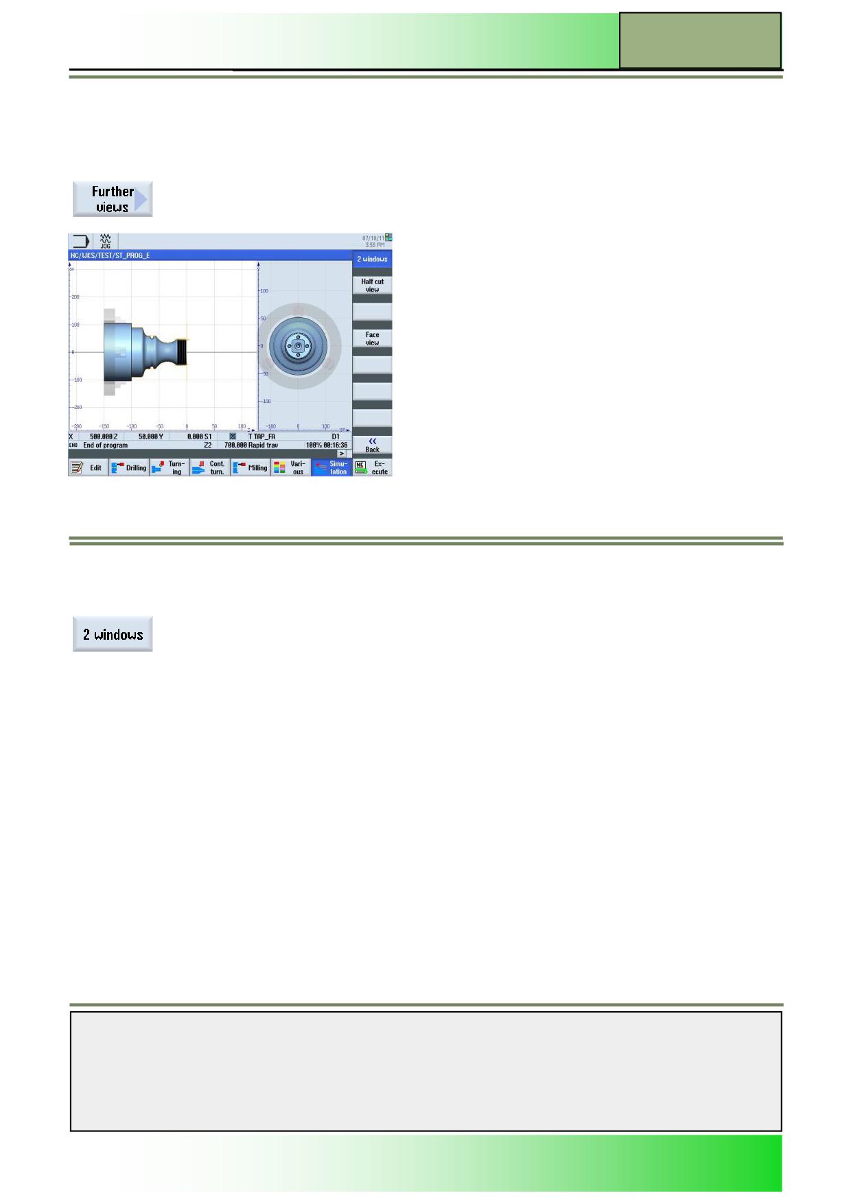
With the function “Further views” a second view of the blank is available and opened in “2 windows”, to view the simulation
process in an optimal way.
Selecting the function “Further views”
By pressing the VSK 1.5 “Further views” a vertical softkey bar opens, with a new option for
viewing the blank and the simulation.
Vertical softkey bar
Display area
Description
By pressing the VSK 1 “2 windows” the simulation window will be split in two sub windows, one
showing the simulation in the side and one in the face view.
Notes
828D/840Dsl SINUMERIK Operate
Page 45
M601
M601
Basics of programming with ShopTurn
Details
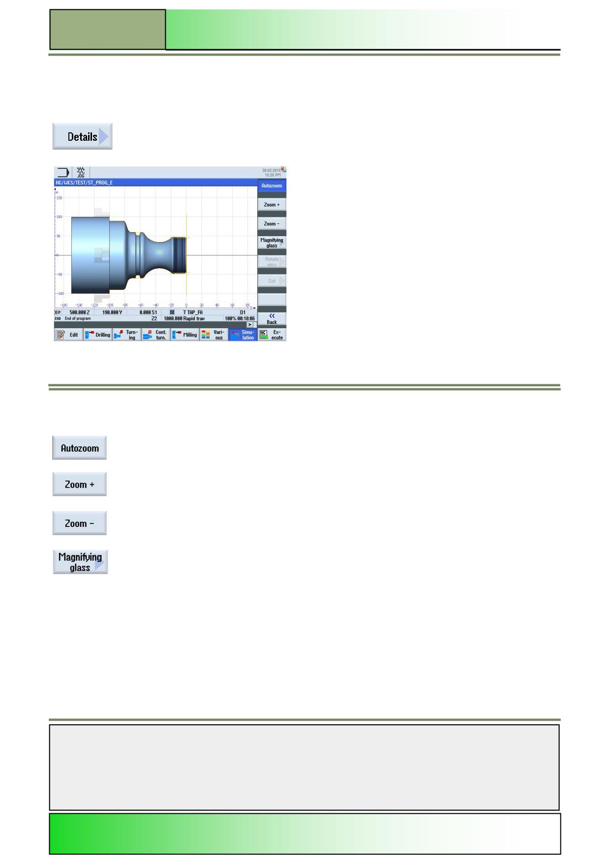
With the function “Details” you can zoom in and zoom out of the workpiece during simulation.
Selecting the function “Details”
By pressing the VSK 1.6 “Details“ the following functions for changing the level of details are
available in a vertical softkey bar:
Vertical softkey bar
Display area
Description
By pressing the VSK 1 “Autozoom“ the workpiece fills out the simulation window in an optimal
way.
By pressing the VSK 2 “Zoom +“ you zoom in into the simulation window. Alternatively you can
press the “+“-key on the number block of the keyboard.
By pressing the VSK 3 “Zoom -“ you can zoom out of the simulation window. Alternatively you
can press the “-“-key on the keyboard.
By pressing the VSK 4 “Magnifying glass” a frame opens in the simulation window, that lets you
zoom in to the extent of the frame size.
Press the VSK1 “Zoom +” to increase and the VSK 2 “Zoom -” to decrease the frame size. Move
the frame with the blue cursor keys on the keyboard.
Press the VSK 8 “Accept” to zoom to the selected extent or abort by pressing the VSK 7
“Cancel”.
Notes
M601
Page 46
828D/840Dsl SINUMERIK Operate
Basics of programming with ShopTurn
M601
Display area
Description (continuation)
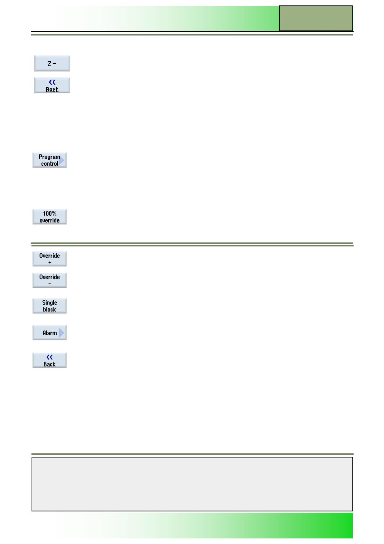
By pressing the VSK 7 “Z-“ the cutting plane will be shifted on the Z-axis (Ablikate) to the neg-
ative (“downward”).
By pressing the VSK 8 “Back” you switch back to the operating area “Details”.
Program control
With the function “Program control” the override can be adjusted for the simulation, the program can be executed in single
blocks and alarm messages, that occurred during simulation, can be displayed.
Selecting the function “Program control”
By pressing the VSK 1.7 “Program control” the following functions will be shown in a vertical
softkey bar on the right side of the screen.
Vertical softkey bar
Display area
Description
By pressing the VSK 1 “100% override” the feedrate override is set to the maximum override
of 100%.
By pressing the VSK 2 “Override +” the override will be increased in 5% steps each time you
press the softkey, until a maximum of 100% is reached.
By pressing the VSK 3 “Override -” the override will be decreased in 5% steps each time you
press the softkey until a minimum of 0% is reached.
With a feedrate override of 0% the simulation is paused.
By pressing the VSK 4 “Single block” the simulation will be executed block by block.
With pressing this softkey the VSK 1.1 “Start” in the operating area “Simulation” will be ex-
changed with the “VSK 1.1 “SBL”.
By pressing the VSK 7 “Alarm” the “Simulation alarms” window opens, with alarm messages
that have occurred during a simulation run.
This can be used for error detection.
By pressing the VSK 8 “Back” you switch back to the vertical softkey bar 1.
Notes
828D/840Dsl SINUMERIK Operate
Page 47
M601
M601
Basics of programming with ShopTurn
Selecting the function “Alarm”
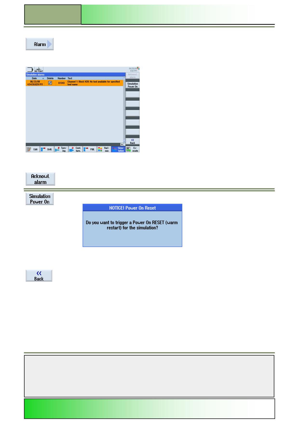
By pressing the VSK 7 “Alarm” the “Simulation alarms” window opens, with a list of all current
active alarm messages that occurred during the simulation.
For error messages and acknowledgement symbols see module - M576 “Operating area Diag-
nostics”,.
Vertical softkey bar
Display area
Description
By pressing the VSK 1 “Acknowl. Alarm” all with the “Reset”- or “Cancel”-symbol marked alarm
messages can be deleted. This softkey is inactive as long as no appropriate error message is
shown.
By pressing the VSK 2 “Simulation Power On” you can trigger a warm restart for the active sim-
ulation.
Press the VSK 8 “OK” to confirm or the VSK 7 “Cancel” to abort the warm restart. With a warm
start the simulation will be ended and started new.
By pressing the VSK 8 “Back” you switch back to the operating area “Program control”.
Notes
M601
Page 48
828D/840Dsl SINUMERIK Operate
Basics of programming with ShopTurn
M601
NC Execute
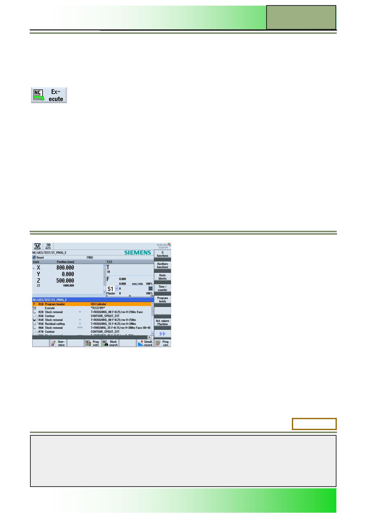
The function “NC Execute” lets you load the active program from the editor
to the operating area “Machine” in the operating mode “AUTO”.
Selecting the function “NC Execute”
By pressing the HSK 1.8 “NC Execute” the control, switches to the operating area “Machine”
under the operating mode “AUTO”.
The program modified in the editor is now ready for machining (see picture below).
In running state this softkey is deactivated
M601: END
Notes
828D/840Dsl SINUMERIK Operate
Page 49
M601

M601
Basics of programming with ShopTurn
Notes
M601
Page 50
828D/840Dsl SINUMERIK Operate
M625
Turning with ShopTurn
Sinumerik
Operate
Module Description:
This module explains the programming of a simple turning example workpiece with ShopTurn func-
tionality by means of different turning cycles (stock removal).
Module Objective:
Working through this module you become familiar with the technology “Turning” by pro-
gramming a ShopTurn program
Content:
Simple programming example
This document was produced for training purposes.
828D/840Dsl SINUMERIK Operate v4.7
Page 1
M625
Siemens assumes no responsibility for its contents.
M625
M625
Page 2
828D/840Dsl SINUMERIK Operate
Turning with ShopTurn
M625
Turning
ShopTurn:
START
Simple
programming
example
Turning
ShopTurn:
END
Notes
828D/840Dsl SINUMERIK Operate
Page 3
M625
M625
Turning with ShopTurn
Simple programming example
Creating a new sequential program
A new ShopTurn program can be created from within the operating modes “JOG, “MDA” and “AUTO” as follows:
1.
Press the “Program Manager”-key on the keyboard.
The program manager will open directly.
- OR -
1.
Press the “MENU SELECT”-key on the operator panel.
Press the yellow HSK 1.4 „Program manager“.
The program manager opens.
2.
Select a drive, where you want to create the program (“NC”, “Local drive”, “USB”).
3.
Press the VSK 2 “New“.
The vertical softkey bar for creating new programs opens.
4.
Press the VSK 3 “ShopTurn” to open the input mask for creating a new ShopTurn sequential
program.
Enter a name for the program in the “Name” field and accept with pressing the VSK 8 “OK”.
The program is loaded to the “editor” and the input mask for the program header is opened by
default.
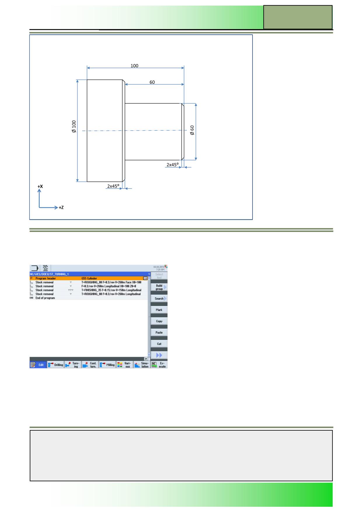
Description:
A simple ShopTurn program (pin) to be programmed with the help of stock removal cycle calls
Objective:
A new ShopTurn program should be created and opened in the editor.
The program header, Stock Removal1, Stock Removal1 and Stock Removal2 cycles and end of the program to be pro-
grammed and subsequently simulated.
The following tools and technology data are required for programming:
Tool and technology da- ROUGHING_80A
ta:
( F 0.250 mm/rev, S 240 m/min)
FINISHING_35A
( F 0.150 mm/rev, S 250 m/min)
Workpiece data:
Blank: Ø 100 x 130 mm
Notes
M625
Page 4
828D/840Dsl SINUMERIK Operate
Turning with ShopTurn
M625
Programming Example : Bolt
The following program will call different stock removal cycles to be programmed.
Creating a new ShopTurn program.
Give the program a name, for example "ST_TURNING_1.MPF".
The window for the program header is automatically opened.
Notes
828D/840Dsl SINUMERIK Operate
Page 5
M625
M625
Turning with ShopTurn
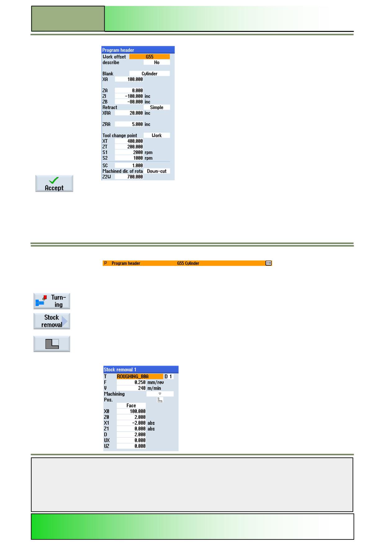
1.
Enter the following values / parameters in the program header:
Press the VSK 8 "Accept" to confirm .
2
The following program block "program head" is inserted in the work plan:
3.
Programming the first stock removal machining.
Press the HSK 1.3 "Turning" to open the turning technology.
Press the VSK 1 "Stock removal".
Press the VSK 3 " to open the input screen for the cycle "Stock removal 1".
4.
Fill in the input mask as follows:
Notes
M625
Page 6
828D/840Dsl SINUMERIK Operate
Turning with ShopTurn
M625
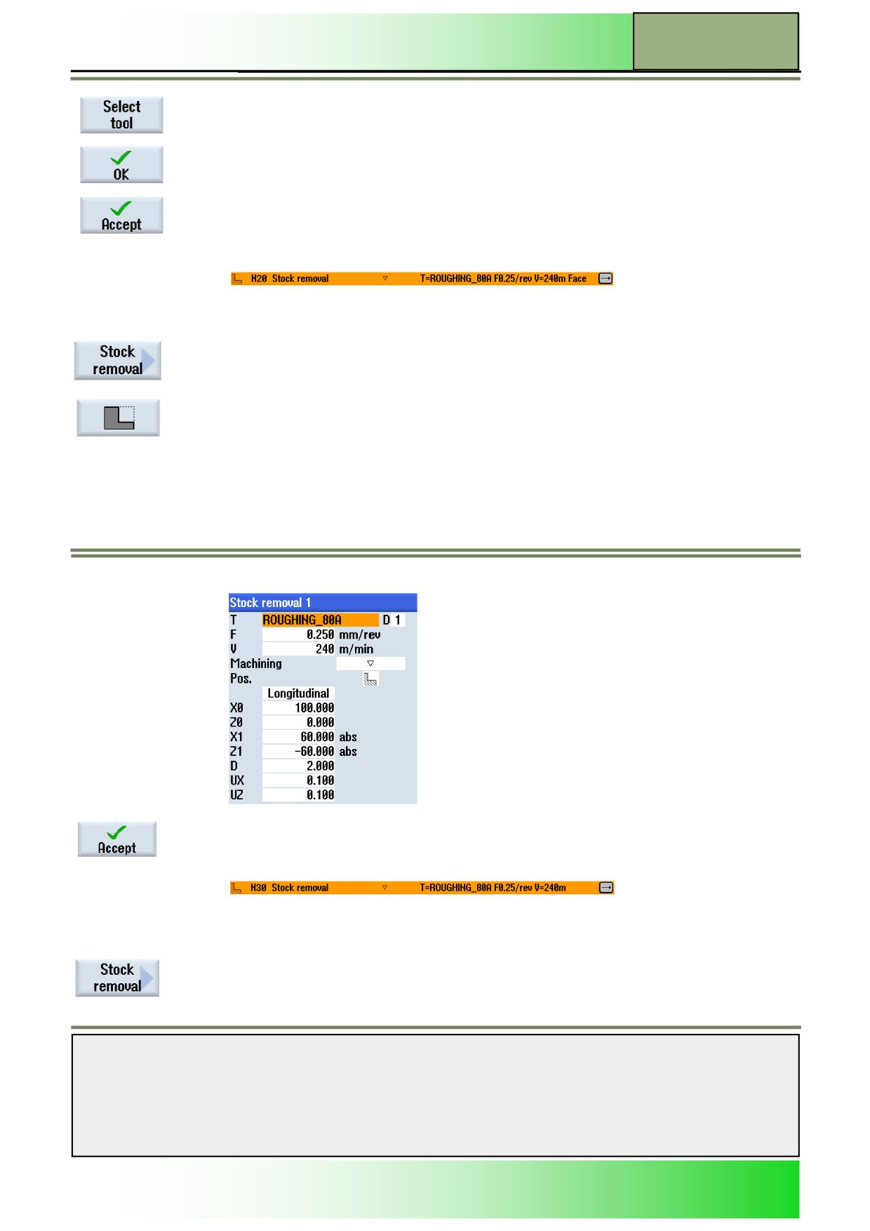
To add a tool, press the
VSK 1 "Select tool".
Select the appropriate tool (ROUGHING_80A) with the orange cursor and press the VSK 8
"OK."
Input with the VSK 8 "Accept" button.
The following program block "Stock removal1" is inserted in the work plan:
5.
Program the second removal machining.
Press the VSK 1 "Stock removal".
Press the VSK 3 " to open the input screen for the cycle "Stock removal 1".
6.
Fill in the input mask as follows:
Press the VSK 8 "Accept" button.
The following program block "removal1" is inserted in the work plan:
7.
Programming the third stock removal machining.
Press the VSK 1 "Stock removal".
Notes
828D/840Dsl SINUMERIK Operate
Page 7
M625
M625
Turning with ShopTurn
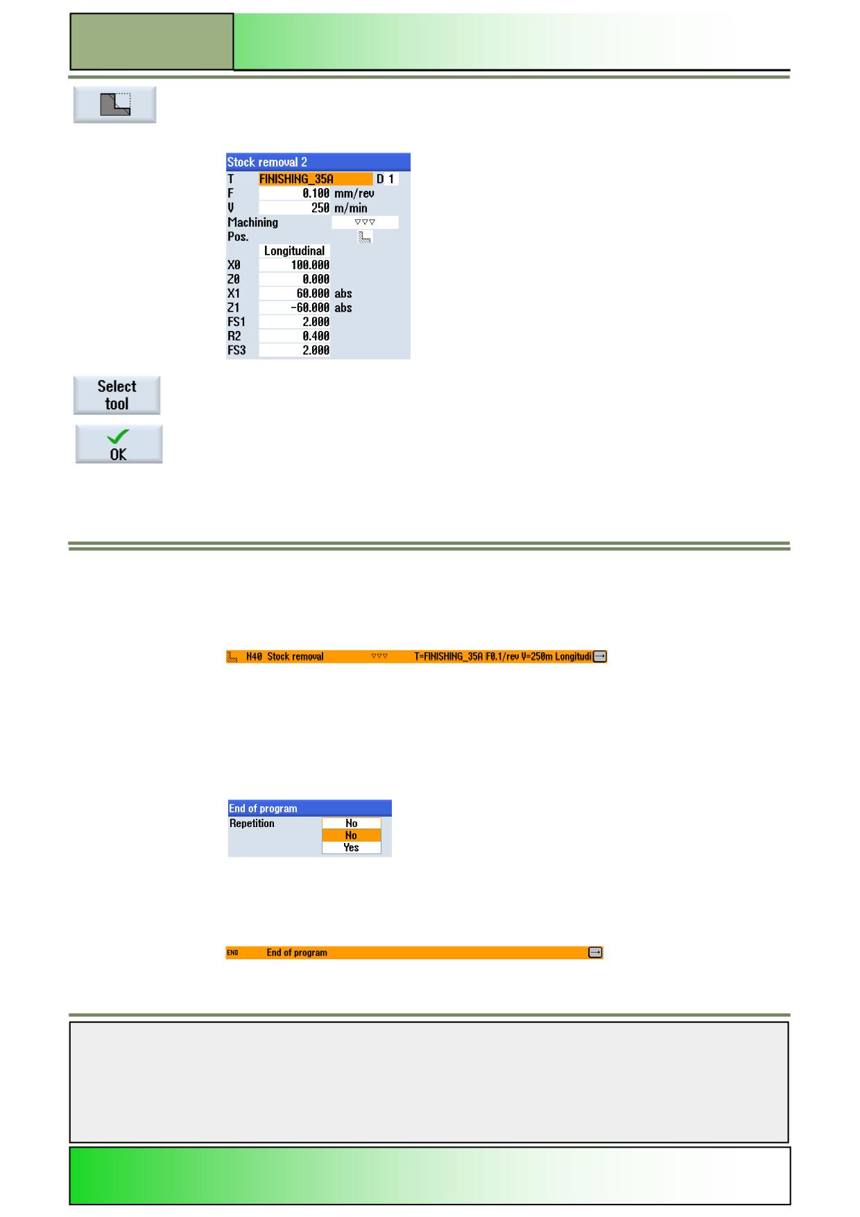
Press the VSK 3 " to open the input screen for the cycle "Stock removal2".
8.
Fill in the input mask as follows:
To add a tool, press the
VSK 1 "Select tool".
Select the appropriate tool (FINISHING_80A) with the orange cursor and press the VSK 8 "OK."
Input with the VSK 8 "Accept" button.
The following program block "Stock removal2" is inserted in the work plan:
9.
Program the “End of the program” and simulate the machining.
Place the orange selection cursor on the program block "program end" and expand the line by
pressing the blue "cursor-to-right" button on the full CNC keyboard.
The input screen for the end of the program opens. Here you can select whether the program
should be repeated for multiple workpieces.
Confirm the default "no" press the VS 8 "Accept."
The program end is updated:
Notes
M625
Page 8
828D/840Dsl SINUMERIK Operate
Turning with ShopTurn
M625
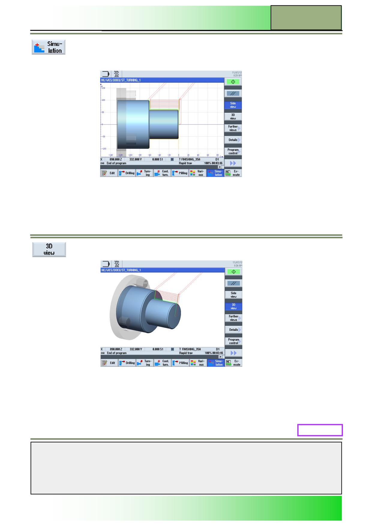
Press the HSK 1.7 "simulation", to start the simulation of the program.
The control calculates the simulation and the simulation window opens.
Press the VSK 1.4 "3D view"., To view the simulation in 3D view.
M625: END
Notes
828D/840Dsl SINUMERIK Operate
Page 9
M625

M625
Turning with ShopTurn
Notes
M625
Page 10
828D/840Dsl SINUMERIK Operate
M610
Drilling with ShopTurn
Sinumerik
Operate
Module Description:
This module explains the programming of a simple drilling example workpiece with ShopTurn func-
tionality by means of chained drilling cycles and position patterns.
Module Objective:
Working through this module you become familiar with the technology “Drilling” by pro-
gramming a chained sequential ShopTurn program.
Content:
Simple programming example
This document was produced for training purposes.
828D/840Dsl SINUMERIK Operate v4.7
Page 1
M610
Siemens assumes no responsibility for its contents.
M610
M610
Page 2
828D/840Dsl SINUMERIK Operate
Drilling with ShopTurn
M610
Drilling
ShopTurn:
START
Simple
programming
example
Drilling
ShopTurn:
END
Notes
828D/840Dsl SINUMERIK Operate
Page 3
M610
M610
Drilling with ShopTurn
Simple programming example
Creating a new ShopTurn program
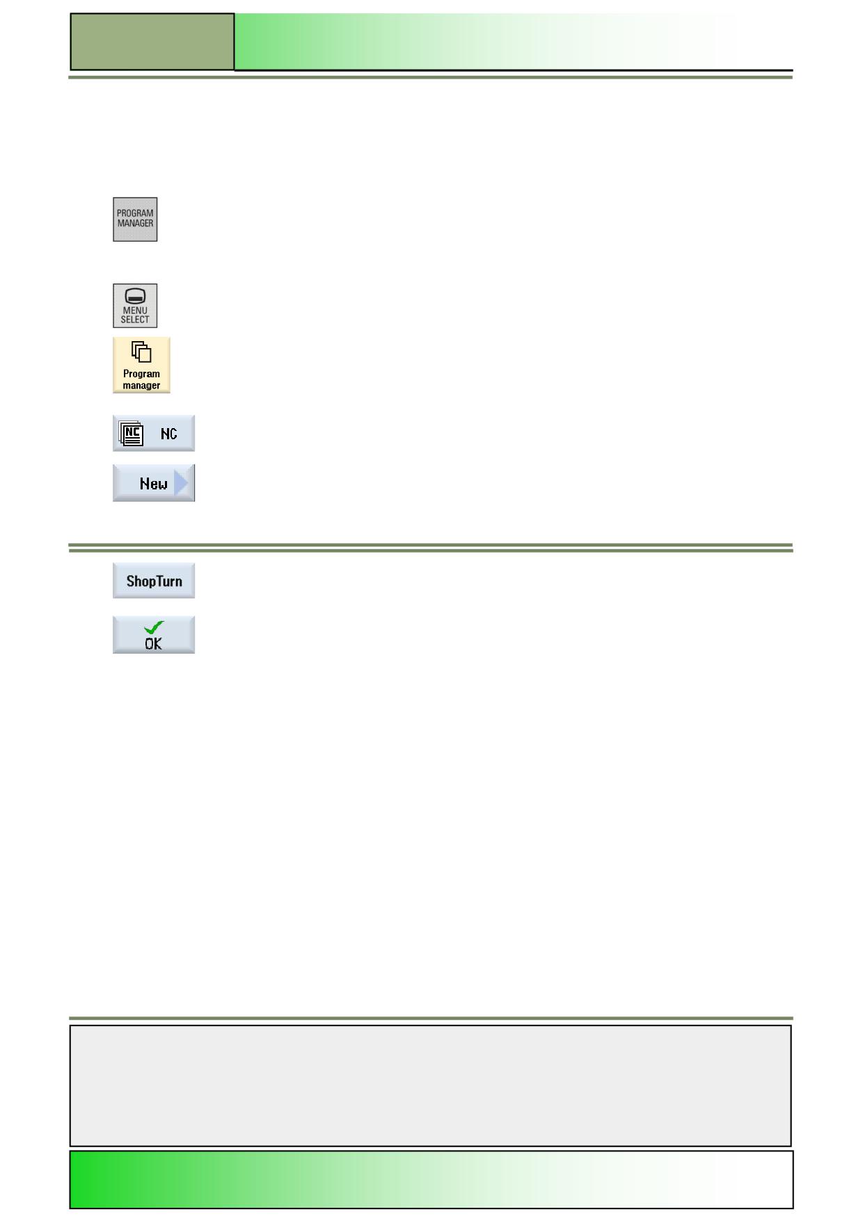
A new ShopTurn program can be created from all operating modes, as follows:
1.
Press the “Program Manager”-key on the keyboard.
The program manager will be opened directly.
- OR -
Press the “MENU SELECT”-key on the operator panel and then the yellow HSK 1.4
1.
„Programm manager“.
The program manager opens.
2.
Select a drive, where you want to create the program (“NC”, “Local drive”, “USB”).
3.
Press the VSK 2 “New“.
The vertical softkey bar with functions for creating new programs opens.
4.
Press the VSK 3 “ShopTurn” to open the input mask for creating a new ShopTurn sequential
program.
Enter a name for the program in the “Name” field and accept with pressing the VSK 8 “OK”.
The program is loaded to the editor and the parameter window for the program header is
opened by default.
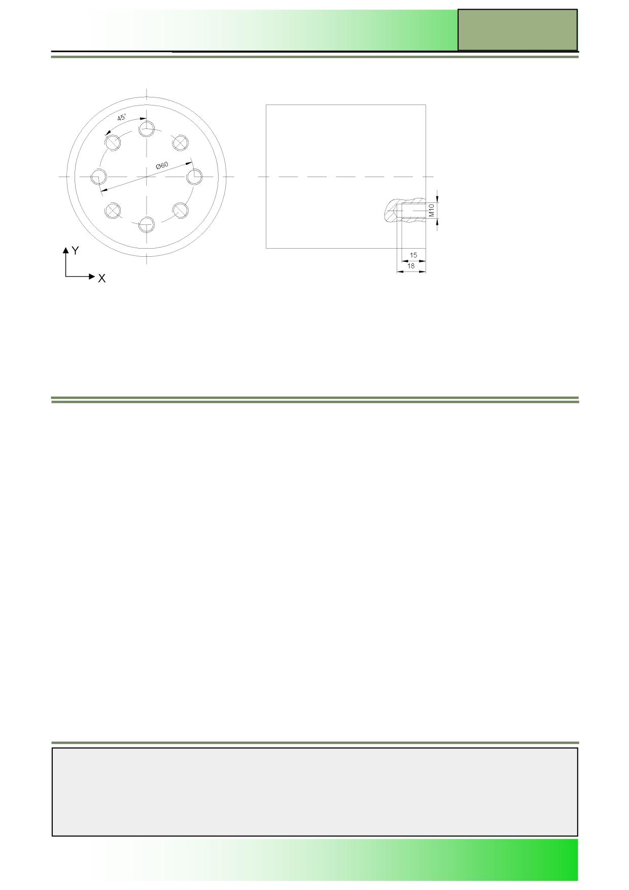
Description:
A simple ShopTurn program, by means of a hole pattern, is to be programmed with help of calling up various drilling cycles
(centring, drilling, tapping and a position pattern).
Objective:
A new ShopTurn-program is to be created and opened in the editor.
The program header, a centric drilling cycle, a position pattern and the program end are to be programmed and simulated.
For this the following tool- and technology data are to be used:
Notes
M610
Page 4
828D/840Dsl SINUMERIK Operate
Drilling with ShopTurn
M610
The following tool- and technology data are needed for the programming:
Tool data:
Centre drill 12 mm (CENTERDRILL_D12)
Drill Ø 8,5 mm (DRILL_D8.5)
Tap M10 (TAP_M10)
Technology data:
F 150 mm/min
S 500 rpm
Approach strategy:
As a start position for the machining, the first programmed drill hole is to be used.
This position is approached in rapid traverse.
Notes
828D/840Dsl SINUMERIK Operate
Page 5
M610
M610
Drilling with ShopTurn
Example: Hole pattern front face
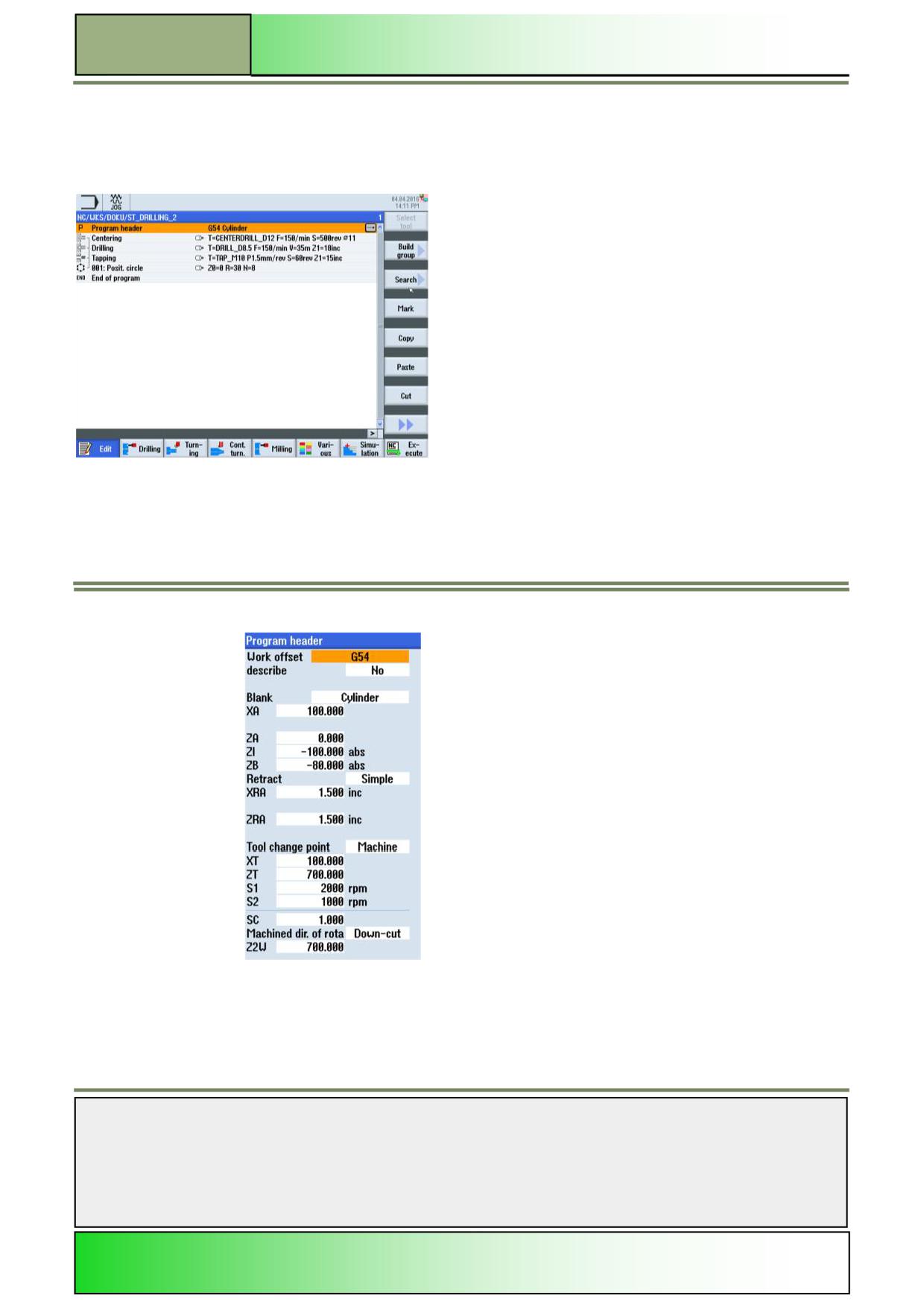
The following program with call up of the drill cycles “Centering”, “Drilling”, “Tapping” and the position pattern “Position cir-
cle” is to be programmed.
Create a new ShopTurn program.
Give the program a name, for example “ST_DRILLING_2.MPF”.
The program with the parameter mask for the program header opens automatically.
1.
Program the program header by entering/selecting the following values/parameters:
Notes
M610
Page 6
828D/840Dsl SINUMERIK Operate
Drilling with ShopTurn
M610
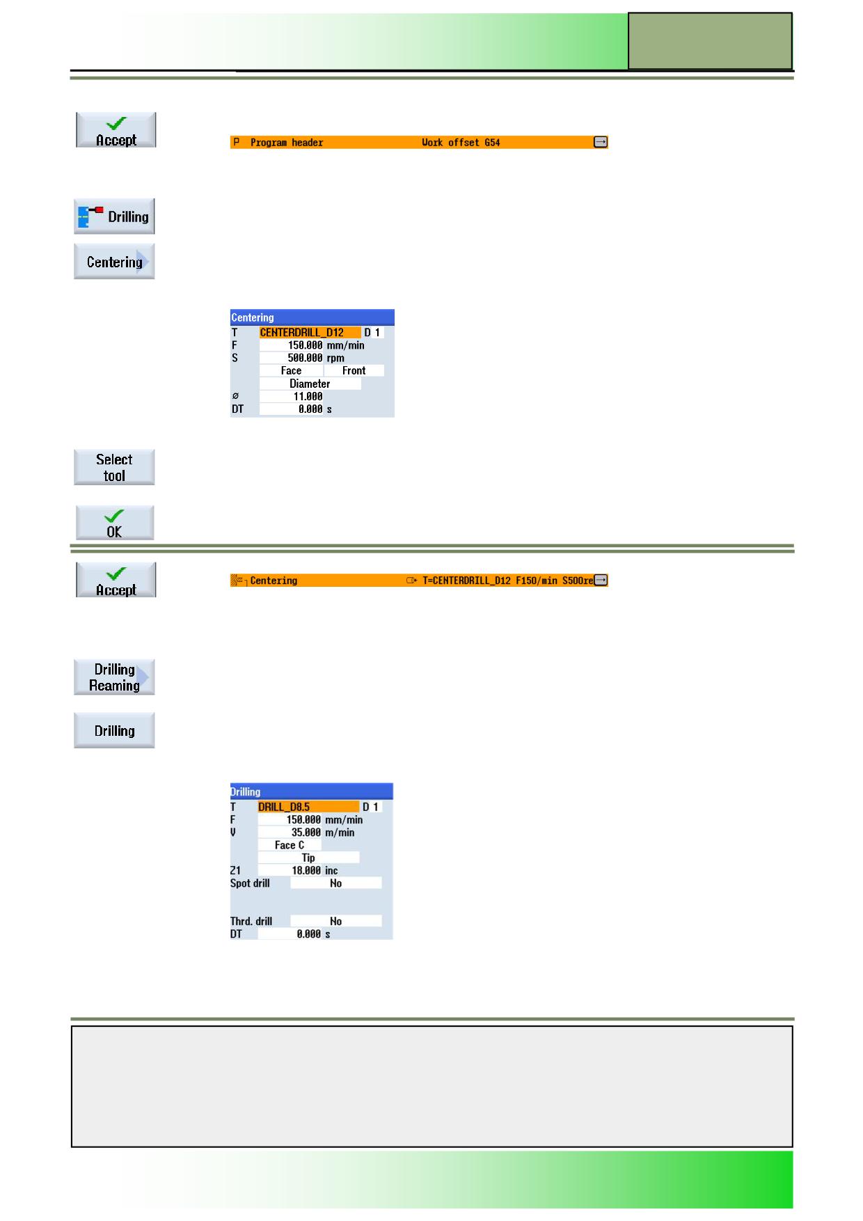
2.
Confirm your inputs by pressing the VSK 8 “Accept”
The following program block “Program header” will be inserted into the work plan:
3.
Start the program by programming a centering drill cycle.
Press the HSK 1.2 “Drill.”, to open the technology for “drilling”.
Press the VSK 2 “Centering”.
The input mask for the “Centering” cycle opens.
3.
Fill out the input mask as displayed below:
To insert a tool into the input mask, press the VSK 1 “Select tool”.
Mark the desired tool (CENTERDRILL_D12) in the tool list with the orange selection cursor and
press the VSK 8 “OK”.
Confirm your inputs by pressing the VSK 8 “Accept”
The following program block “Centering” will be inserted into the work plan:
The program chain starts (note the opened bracket on the right side of the icon)
4.
Now, program the drill cycle.
Press the VSK 3 “Drilling Reaming”, to open the technology for “Drilling Reaming”.
Select the VSK 3 “Drilling” to open the input mask for the “drilling” cycle.
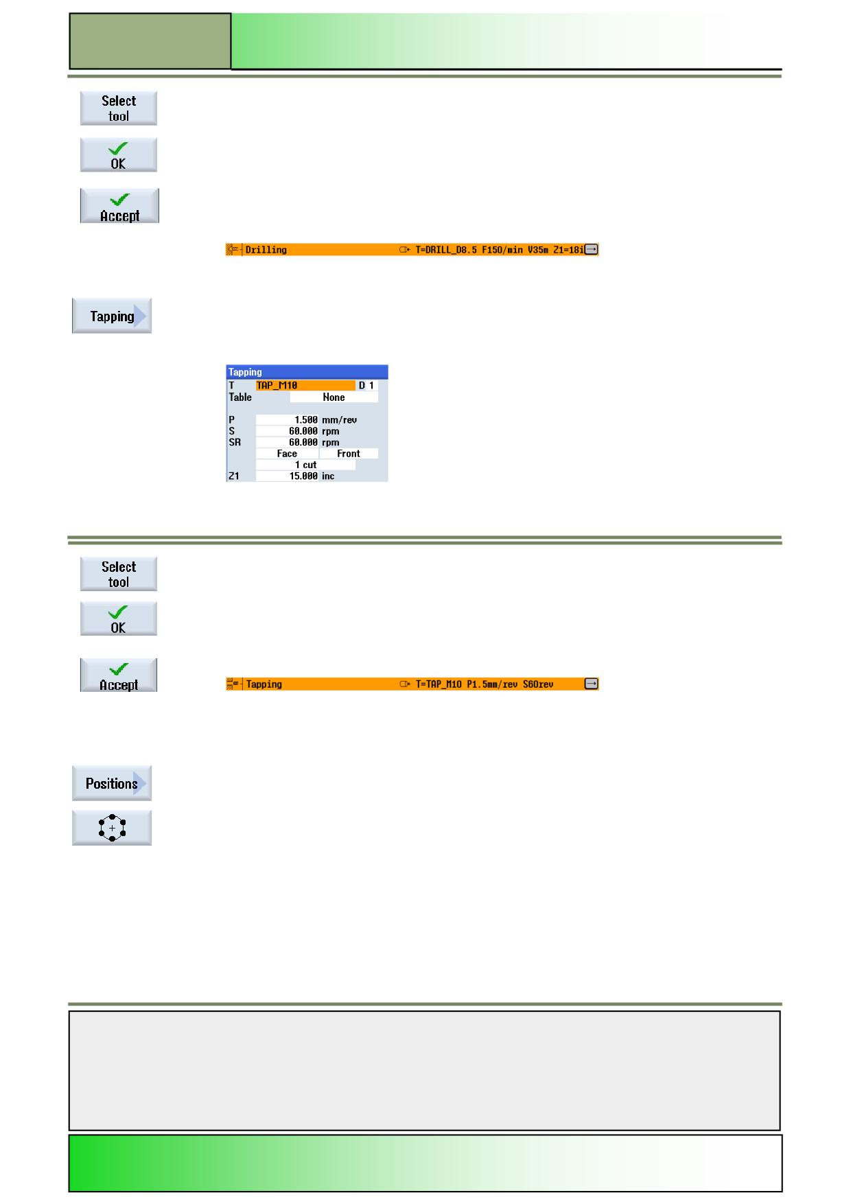
5.
Fill out the input mask as displayed below:
Notes
828D/840Dsl SINUMERIK Operate
Page 7
M610
M610
Drilling with ShopTurn
To insert a tool into the parameter window, press the VSK 1 “Select tool”.
Mark the desired tool (DRILL_D8.5) in the tool list with the orange selection cursor and press the
VSK 8 “OK”.
Confirm your inputs by pressing the VSK 8 “Accept”.
The following program block “Drilling” will be inserted into the work plan:
The program chain will be extended.
(Note the bilateral opened bracket on the right side of the icon).
6.
Program now the tapping cycle.
Press the VSK 5 “Threading” followed by VSK 3 “Tapping”.
The input mask for the “Tapping”-cycle opens.
7.
Fill out the input mask as displayed below:
To insert a tool into the parameter mask, press the VSK 1 “Select tool”.
Mark the desired tool (TAP_M10) in the tool list with the orange selection cursor and press the
VSK 8 “OK”.
Confirm your inputs by pressing the VSK 8 “Accept”
The following program block “Tapping” will be inserted into the work plan:
The program chain will be extended.
(Note the bilateral opened bracket on the right side of the icon)
8.
Program now the position pattern for the drilling, in order to close the program block chain.
Press the VSK 7 „Positions“.
The positions input mask opens.
To set the positions for the drillings press the VSK 5 “Position circle”.
The “Position circle” input mask opens.
Notes
M610
Page 8
828D/840Dsl SINUMERIK Operate
Drilling with ShopTurn
M610
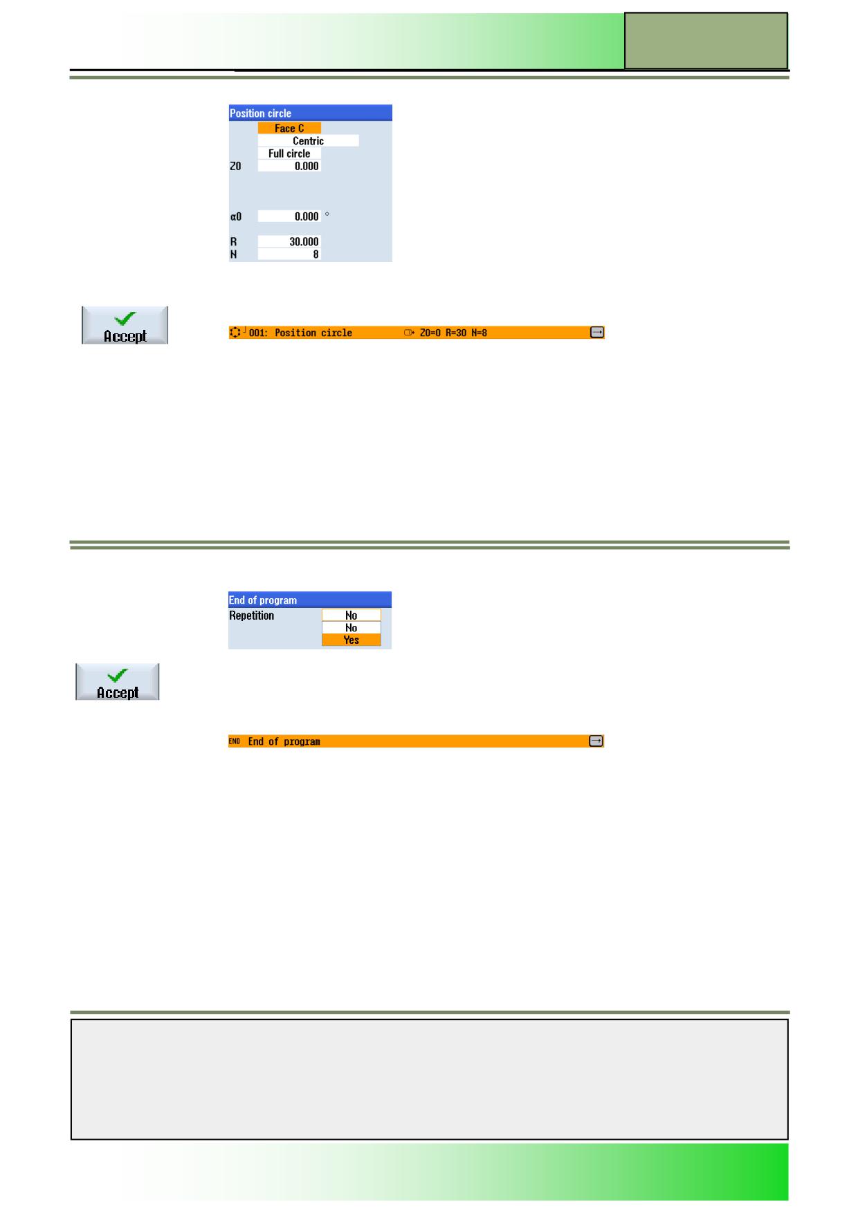
9.
Fill out the input mask as displayed below:
Confirm your inputs by pressing the VSK 8 “Accept”.
The following program block “Position circle” will be inserted into the work plan:
The program chain will be closed.
(Note the downward closed bracket on the right side of the icon).
10.
Program now the program end and simulate the machining.
Place the orange selection cursor on the “End of Program” program block.
Extend the program block by pressing the blue “cursor-to-the-right”-key on the keyboard.
The input mask for the program end opens.
11.
The settings window for the program end opens, where you can define to repeat the workpiece.
Accept the default value by pressing the VSK 8 “Accept”.
The program block “End of program” will be updated.
Notes
828D/840Dsl SINUMERIK Operate
Page 9
M610
M610
Drilling with ShopTurn
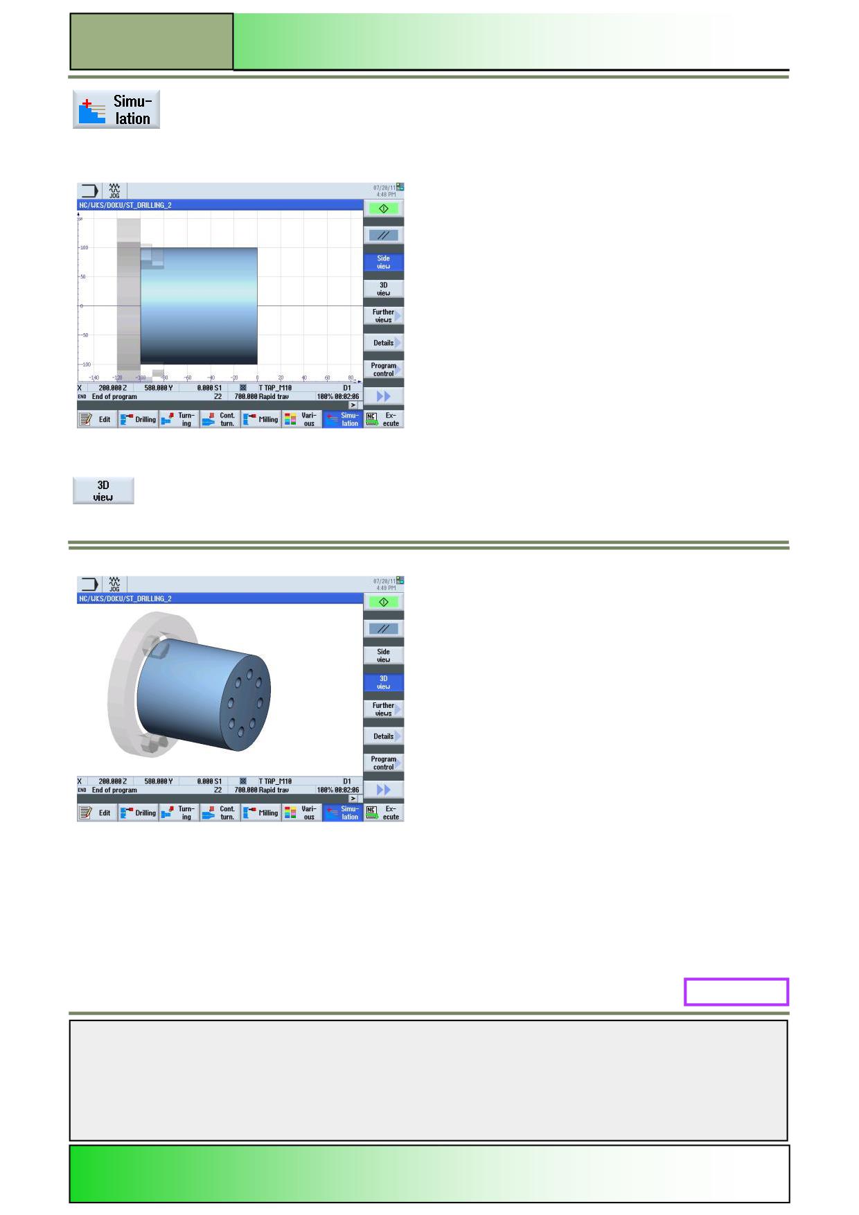
Press the HSK 1.7 “Simulation” to start the simulation of the program.
The control calculates the simulation parameters and opens the simulation in the simulation win-
dow in “Side view” by default.
To view the simulation in a view on the face of the workpiece, press the VSK 1.4 “3D view”.
M610: END
Notes
M610
Page 10
828D/840Dsl SINUMERIK Operate
M633
Contour turning with ShopTurn
Sinumerik
Operate
Module Description:
This module explains the programming of a complex ShopTurn program, by using contour cycle
chained together with a stock removal cycle
Module Objective:
Working through this module you become familiar with the technology “Contour turning”
by programming a chained sequential ShopTurn program.
Content:
Complex programming example
This document was produced for training purposes.
828D/840Dsl SINUMERIK Operate v4.7
Page 1
M633
Siemens assumes no responsibility for its contents.
M633
M633
Page 2
828D/840Dsl SINUMERIK Operate
Contour turning with ShopTurn
M633
Contour turning
ShopTurn:
START
Complex
programming
example
Contour turning
ShopTurn:
END
Notes
828D/840Dsl SINUMERIK Operate
Page 3
M633
M633
Contour turning with ShopTurn
Complex programming example
Creating a new sequential ShopTurn program
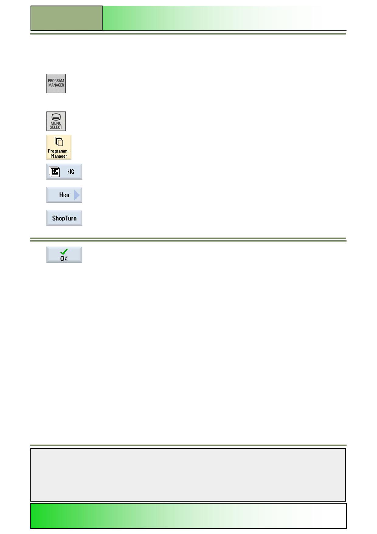
A new ShopTurn program can be created in all operating modes, as follows:
1.
Press the “Program Manager”-key on the keyboard.
The program manager will be opened directly.
- OR -
1.
Press the “MENU SELECT”-key on the operator panel.
Press the HSK 4 “Program Manager”.
The program manager opens.
2.
Select a drive, where you want to create the program (“NC”, “Local drive”, “USB”).
3.
Press the VSK 2 “New“.
The vertical softkey bar for creating new programs opens.
4.
Press the VSK 3 “ShopTurn” to open the input mask for creating a new ShopTurn sequential
program.
5.
Enter a name for the program in the “Name” field and accept with pressing the VSK 8 “OK”.
The program is loaded to the “editor” and the input mask for the program header is opened by
default.
Description:
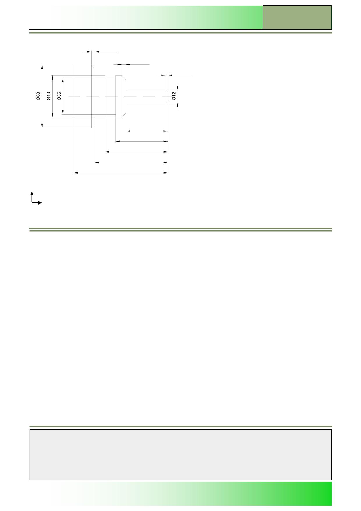
A more complex ShopTurn sequential program (SHAFT) is to be programmed, by using different turning cycles (contour,
stock removal, groove cutting).
Objective:
The workpiece shown below is to be programmed.
Then the program is to be simulated.
Notes
M633
Page 4
828D/840Dsl SINUMERIK Operate
Contour turning with ShopTurn
M633
3x45°
4x45°
2x45°
40
50
60
70
90
X
Z
The following tool and technology data are to be used for programming:
Tool- and
ROUGHING_80A
technology data:
(F 0,3 mm/min, V 260 m/min)
FINISHING_35A
(F 0,15 mm/min V 270 m/min)
GROOVE_3A
(F 0,08 mm/min, 2000 rpm)
Approach strategy:
The following position is programmed as the
contour starting point:
X
12
Z
0
This point will be approached in the cycle automatically with rapid traverse.
Notes
828D/840Dsl SINUMERIK Operate
Page 5
M633
M633
Contour turning with ShopTurn
Programming example
The following program is to be created, with the call up of multiple contour descriptions, as well as stock removal- and the
residual cutting cycles.
1.
Create a new ShopTurn sequential program.
Give the program a name, for example “ST_CONTOURTURNING_2.MPF“.
The program, with the parameter mask for the program header opens by default.
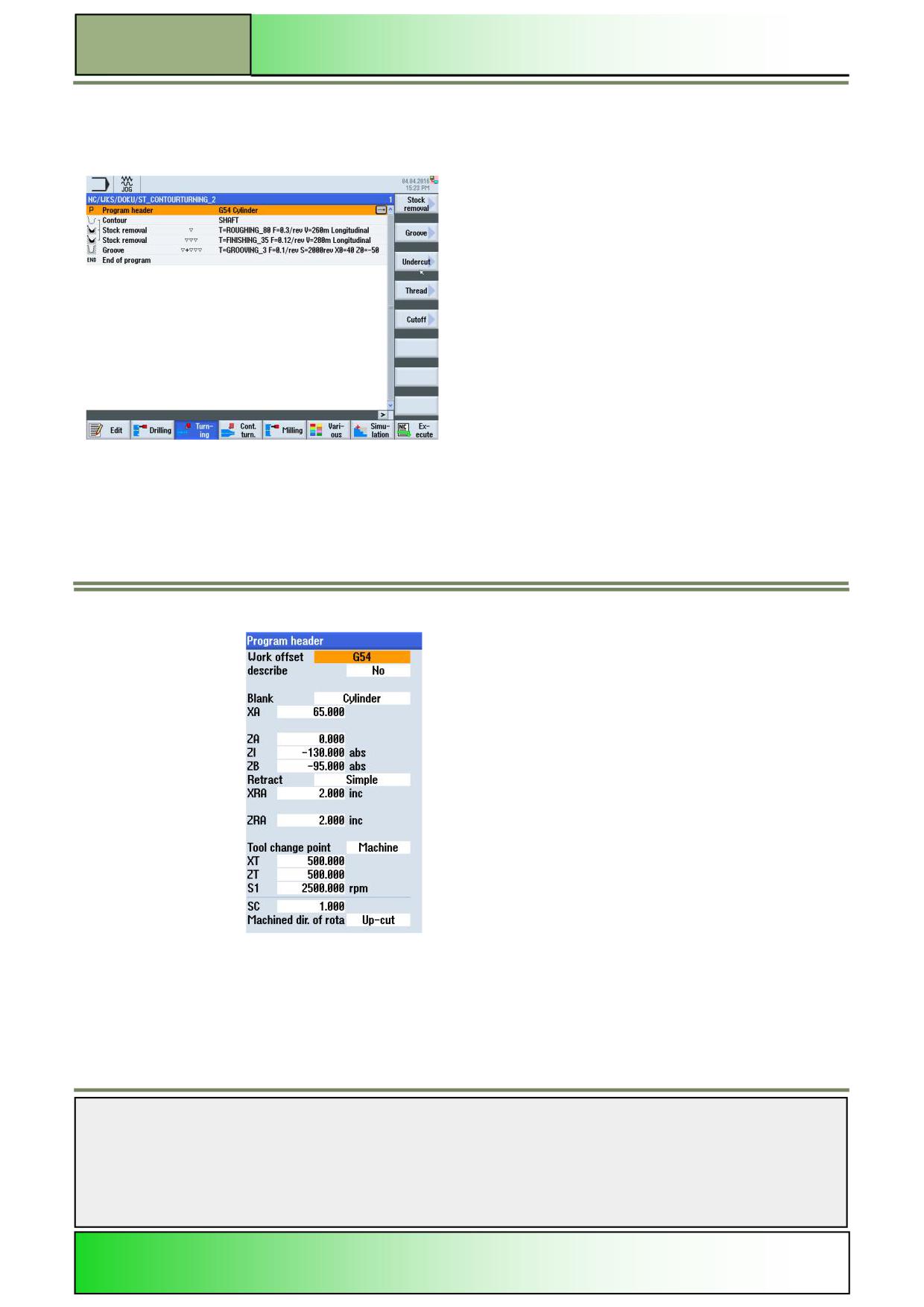
2.
Enter the following values into the program header:
Notes
M633
Page 6
828D/840Dsl SINUMERIK Operate
Contour turning with ShopTurn
M633
Accept your inputs by pressing the VSK 8 “Accept”.
The following program block “Program header” will inserted into the work plan:
3.
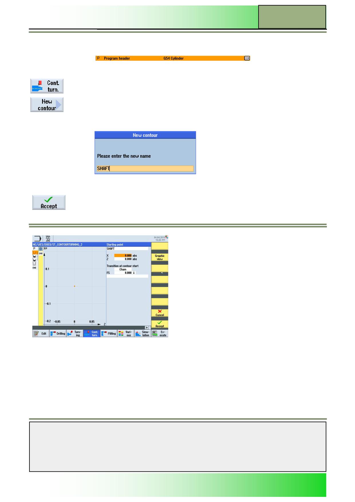
Program the first contour description.
Press the HSK 1.4 “Cont. turn.”, to open the technology “Contour turning”.
Press the VSK 1 “New contour”.
The “New contour” input mask opens where you can enter a suitable name for the new contour.
4.
Enter a name for the contour, e.g. “SHAFT” as
follows:
Accept your input by pressing the VSK 8 “Accept”.
The contour editor for the contour description opens, with the input window for defining the start-
ing point of the contour (recognizable by the yellow bar with the contour elements and program-
ming symbols on the left edge of the screen, and the yellow vertical softkey-bar on the right edge
of the screen):
Notes
828D/840Dsl SINUMERIK Operate
Page 7
M633
M633
Contour turning with ShopTurn
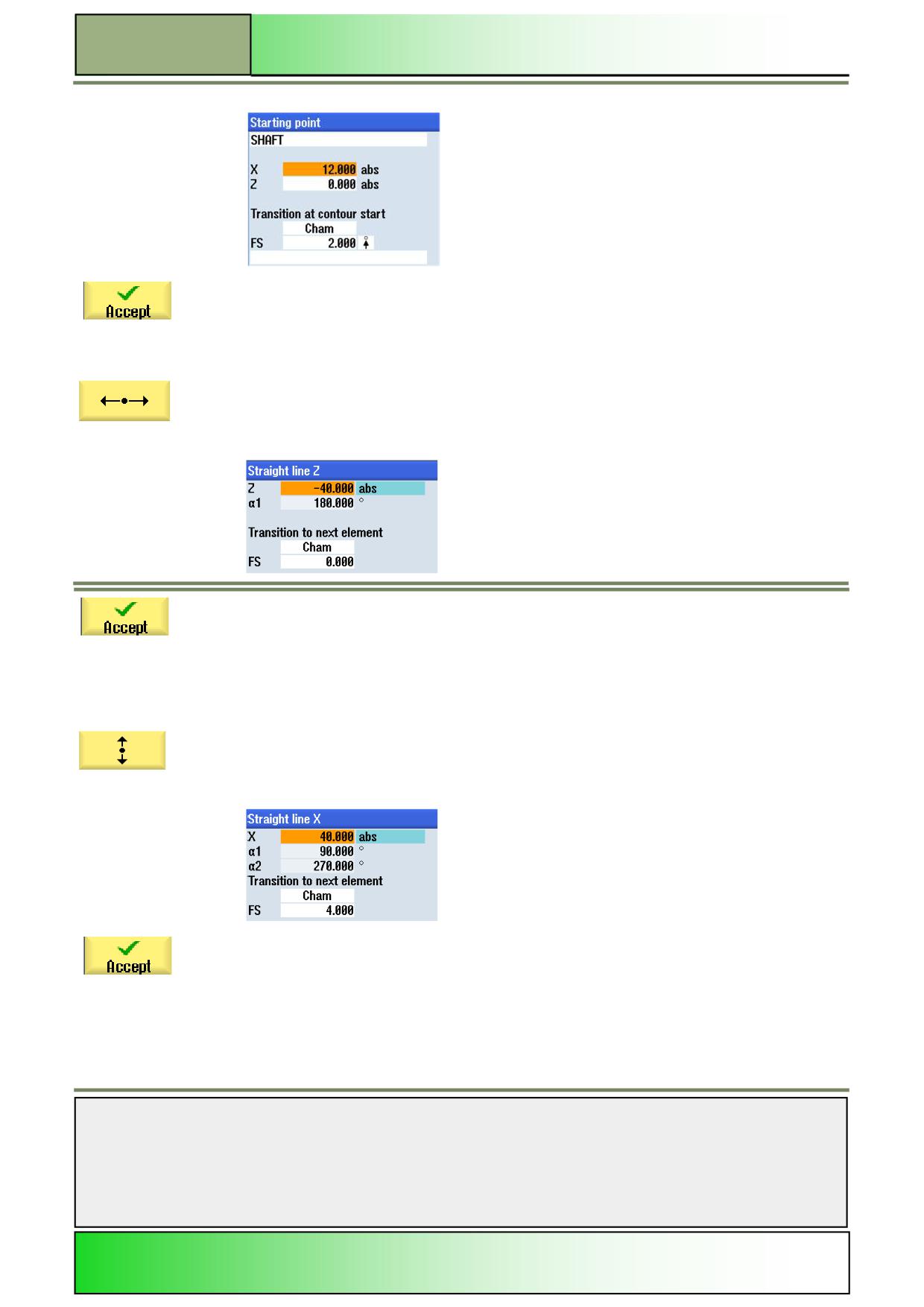
5.
Enter the following coordinates as starting point:
Accept your inputs by pressing the VSK 8 “Accept”.
6.
Extend the contour by adding a straight line in
X-direction.
Press the VSK 1.3 “Straight line Z” to open the input mask for the “Straight line Z” contour
element.
7.
Enter the following coordinates into the input mask:
Accept your inputs by pressing the VSK 8 “Accept”.
Note:
The starting angle to the Z-axis “α1” is calculated automatically, by entering the Z value.
8.
Extend the contour by adding a straight line in
Z-direction.
Press the VSK 1.2 “Straight line X” to open the input mask for the contour element “Straight line
X”.
9.
Enter the following coordinates into the input mask:
Accept your inputs by pressing VSK 8 “Accept”.
Note:
By entering the value X, the values for “α1” and “α2” are calculated automatically from the previ-
ous contour element and the current entered position.
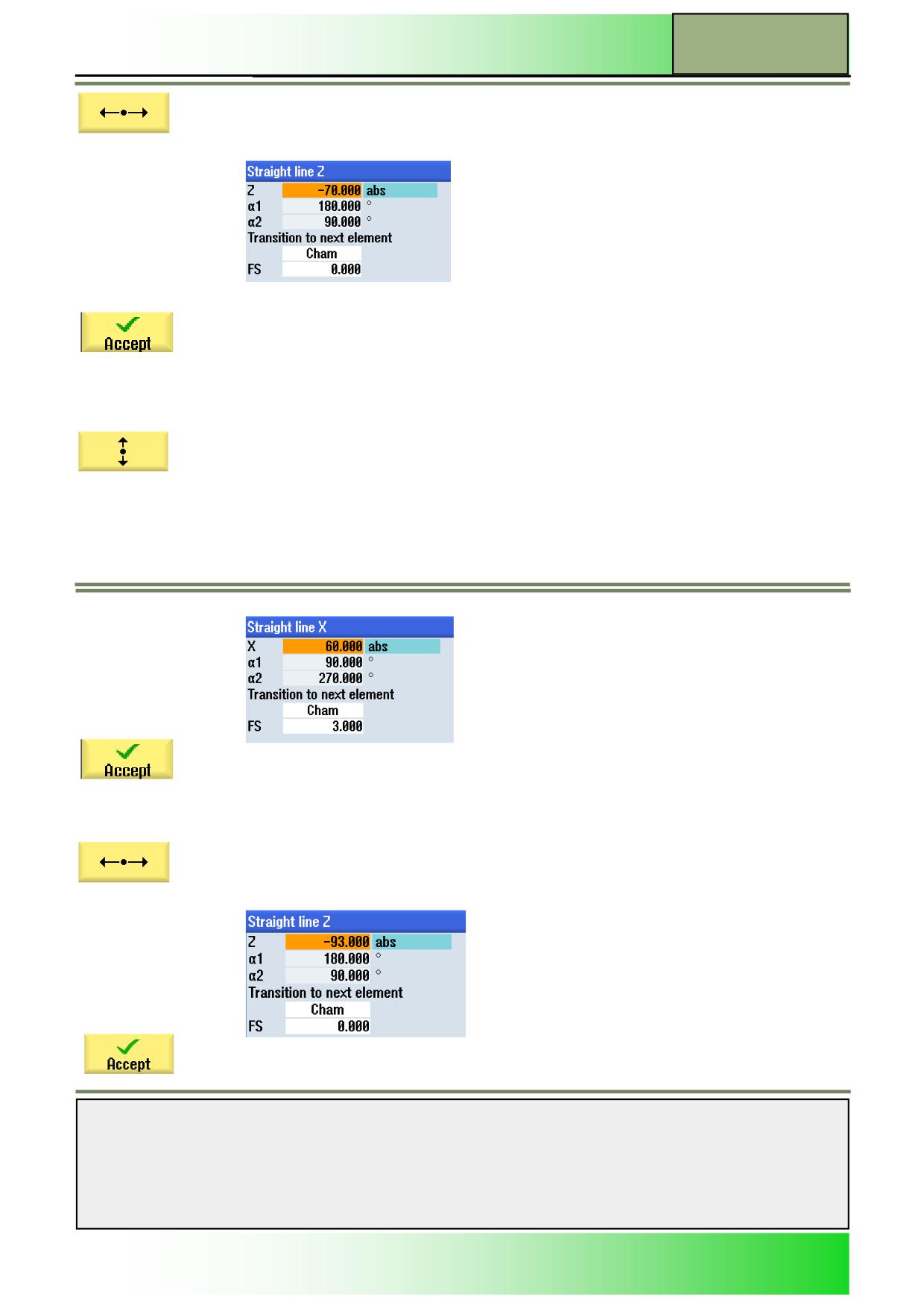
10
Extend the contour by adding a straight line in Z-direction.
Notes
M633
Page 8
828D/840Dsl SINUMERIK Operate
Contour turning with ShopTurn
M633
Press the VSK 1.4 “Straight Z” to open the input mask for the contour element “Straight Z”.
11.
Enter the following coordinates into the input mask:
Confirm your inputs by pressing the VSK 8 “Accept”.
Note:
By entering the value for the parameter “Z” , the
values for “α1” and “α2” are calculated automatically.
12.
Extend the contour by adding a straight line in Z-direction.
Press the VSK1.2 “Straight line X” to open the input mask for the contour element “Straight line X” .
13.
Enter the following coordinates into the input mask:
Confirm your inputs by pressing the VSK 8 “Accept”.
Note:
By entering the value for the parameter “” , the values for “α1” and “α2” are calculated automatically.
14.
Extend the contour by adding a straight line in direction Z.
Press the VSK 1.4 “Straight Z“ to open the input mask for the contour element “Straight Z”.
15.
Enter the following coordinates into the input mask:
Confirm your inputs by pressing the VSK 7 “Accept”.
Notes
828D/840Dsl SINUMERIK Operate
Page 9
M633
M633
Contour turning with ShopTurn
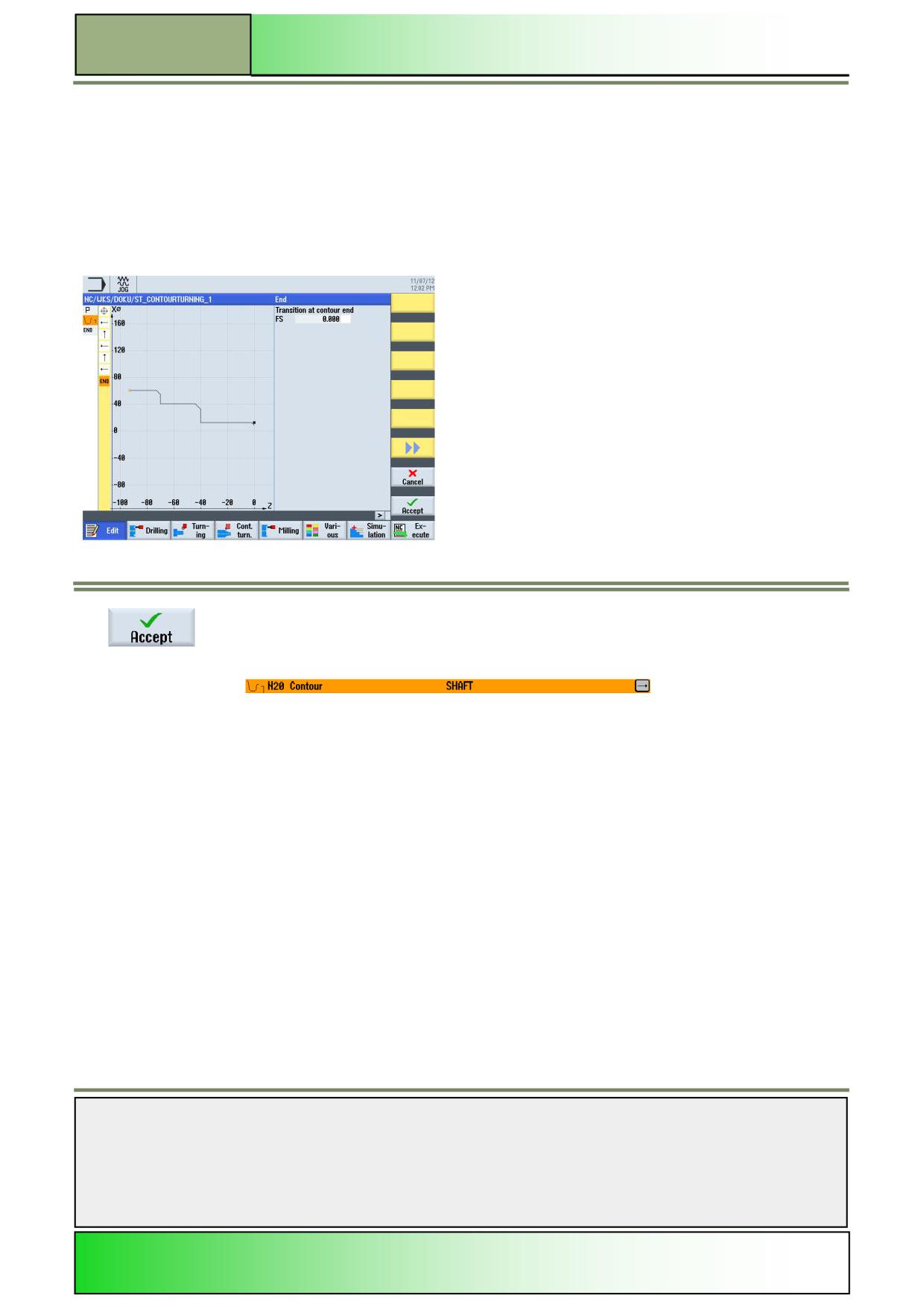
16.
Now, examine the finished contour outline.
For this, switch with the orange selection cursor to the yellow contour step bar on the left side of
the screen, by pressing blue “cursor-to-the-left”-key on the keyboard.
Place the orange selection cursor on the “END”-Symbol in the yellow contour step bar by using
the blue “cursor-down”-key on the keyboard.
The following screen with a sketch of the contour description will be displayed.
The screen below with the finished contour description:
17.
Finish the contour by pressing the VSK 8 “Accept”.
The following program block “Contour” will be
inserted into the work plan:
The program chain opens (recognizable by the downward opened bracket right beside the pro-
gramming symbol).
Notes
M633
Page 10
828D/840Dsl SINUMERIK Operate
Contour turning with ShopTurn
M633
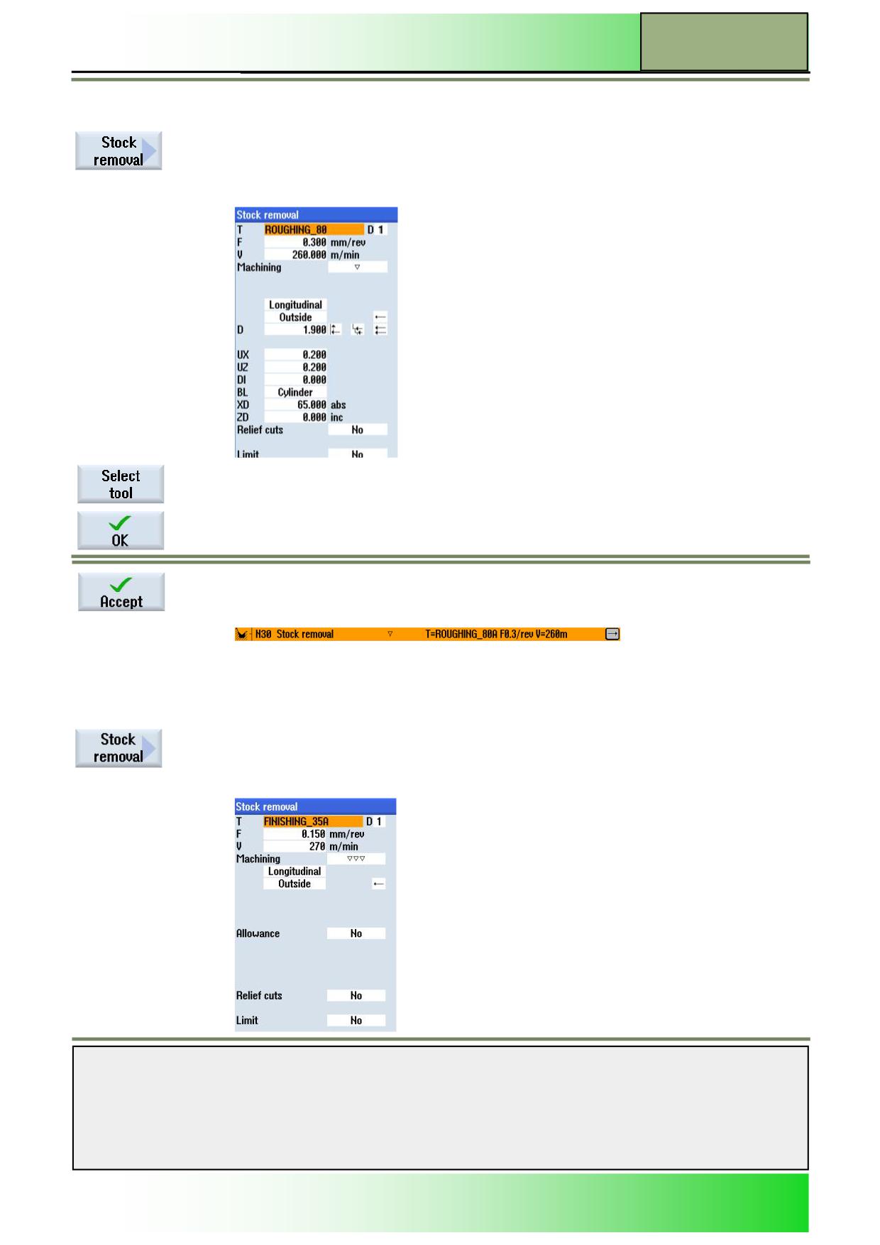
18.
Insert a stock removal cycle into the program.
Press the HSK “Cont. turn.” followed by VSK 1.2 “Stock removal” to open the input mask for
the “Stock removal” cycle.
19.
Fill out the input mask as follows:
In order to insert a tool into the parameter mask, press the VSK 1 “Select tool”.
Mark the appropriate tool (ROUGHING_80A) with the orange selection cursor and press the
VSK 8 “OK”.
Confirm your inputs by pressing the VSK 8 “Accept”.
The program block “Stock removal” will be inserted into the work plan:
The program chain is extended.
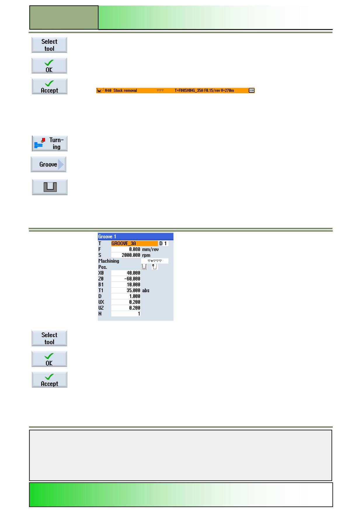
20.
Insert a “Stock removal” cycle into the program.
Press the VSK 1.2 “Stock removal” to open the parameter mask for the “Cut residual material”
cycle.
21.
Fill out the parameter mask as follows:
Notes
828D/840Dsl SINUMERIK Operate
Page 11
M633
M633
Contour turning with ShopTurn
In order to insert a tool into the parameter mask, press the VSK 1 “Select tool”.
Mark the appropriate tool (FINISHING_35A) with the orange selection cursor and press the VSK
8 “OK”.
Confirm your inputs by pressing the VSK 8 “Accept”.
The program block “Stock removal” will be inserted into the work plan:
The program chain is extended.
22.
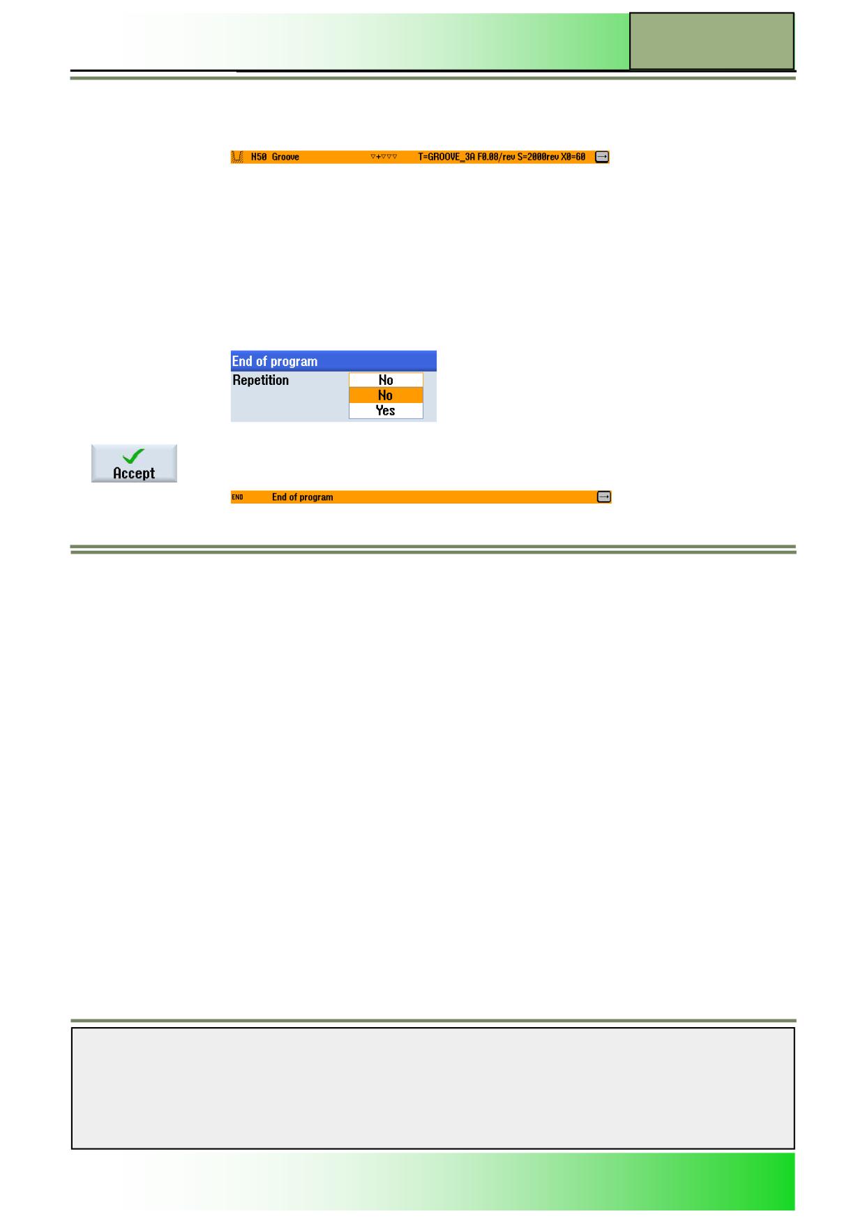
The next machining step, program a “Groove” cycle.
Press the HSK 3 "Turning" to open the technology "Turning" menu.
Press the VSK 2 “Groove” to open the input mask for the “Stock removal” cycle.
Press the VSK 1.3 "Groove 1" to enter the input mask of Grooving.
23.
Fill out the parameter mask as follows
In order to insert a tool into the parameter mask, press the VSK 1 “Select tool”.
Mark the appropriate tool (GROOVE_3A) with the orange selection cursor and press the VSK 8
“OK”.
Confirm your inputs by pressing the VSK 8 “Accept”.
Notes
M633
Page 12
828D/840Dsl SINUMERIK Operate
Contour turning with ShopTurn
M633
The program block “Groove” will be inserted into the work plan:
24.
Program the end of the program and simulate the machining of the program.
Place the orange selection cursor on the program block “End of program” and extend the pro-
gramming block by pressing the blue “cursor to-the-right” key on the keyboard.
25.
The settings window for the program end opens, where you can define to repeat the workpiece.
Accept the default setting “No” by pressing the VSK 8 “Accept”.
The program block “End of program” is updated.
Notes
828D/840Dsl SINUMERIK Operate
Page 13
M633
M633
Contour turning with ShopTurn
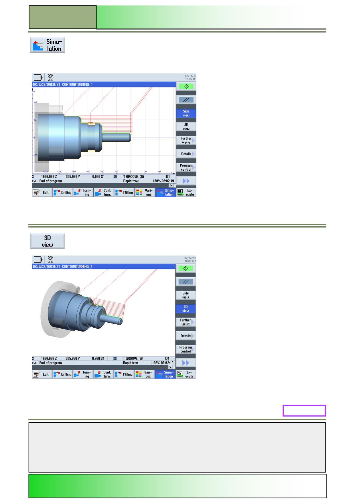
Press the HSK 1.7 “Simulation“ to start the simulation of the program run.
The control calculates the simulation and starts the simulation in an animation window showing
the machining in a side view on the blank.
To switch to face view, press the VSK 1.4 “3D view”.
M633: END
Notes
M633
Page 14
828D/840Dsl SINUMERIK Operate
M641
Straight Circle with ShopTurn
Sinumerik
Operate
Module Description:
This module explains the programming of a contour machining operation with the function “Straight
Circle”.
Module Objective:
Working through this module you become familiar with the function “Straight Circle” in
ShopTurn by programming with ShopTurn functionality.
Content:
Simple programming example
This document was produced for training purposes.
828D/840Dsl SINUMERIK Operate v4.7
Page 1
M641
Siemens assumes no responsibility for its contents.
M641
M641
Page 2
828D/840Dsl SINUMERIK Operate
Straight Circle with ShopTurn
M641
Straight
Circle:
START
Simple
programming
example
Straight
Circle:
END
Notes
828D/840Dsl SINUMERIK Operate
Page 3
M641
M641
Straight Circle with ShopTurn
Simple programming example
Creating a new ShopTurn program
A new ShopTurn program can be created in all operating modes, as follows:
1.
Press the “Program Manager”-key on the keyboard.
The program manager opens directly.
- OR -
1.
Press the “MENU SELECT”-key on the operator panel.
Press the yellow HSK 4 “Program Manager”.
The program manager opens.
2.
Select a drive, where you want to create the program by pressing the corresponding horizontal
softkey (“NC”, “Local drive”, “USB”).
3.
Press the VSK 2 “New“.
The vertical softkey bar for creating new programs opens.
4.
Press the VSK 3 “ShopTurn” to open the input mask for creating a new ShopTurn sequential
program.
Enter a name for the program in the “Name” field and accept with pressing the VSK 8 “OK”.
The program is loaded to the editor and the input mask for the program header is opened by
default.
Description:
A simple program (shaft) is to be programmed, by using the function “Straight Circle”.
Objective:
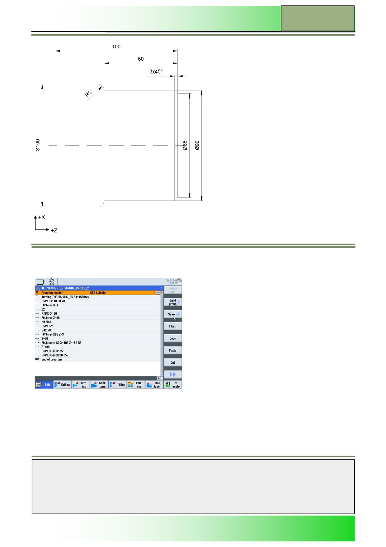
A new ShopTurn program to machine the workpiece below is to be created.
The program header, several “Straights” and “Circles” as well as the program end are to be programmed. Afterwards the
program is to be simulated.
The following data are to be used for the programming:
Tool data:
Finishing tool 55° (FINISHING_TOOL_55)
Technology data:
S 1500 rpm F 0.3mm/rev
Blank dimensions:
Ø 105 x 102 mm
Work steps:
- Planar cut to Z = 0.
- Machining step Ø 90 x 60 mm with one cut.
- Machining of the finished diameter including the
machining of the chamfer 3x45° and the radius R5.
Notes
M641
Page 4
828D/840Dsl SINUMERIK Operate
Straight Circle with ShopTurn
M641
Programming example: Shaft
The following ShopTurn program is to be created:
1.
Create a new ShopTurn program.
Give the program the name, for example.
“ST_STRAIGHT_CIRCLE_2.MPF“.
The program, with the input mask for the program header opens by default.
Notes
828D/840Dsl SINUMERIK Operate
Page 5
M641
M641
Straight Circle with ShopTurn
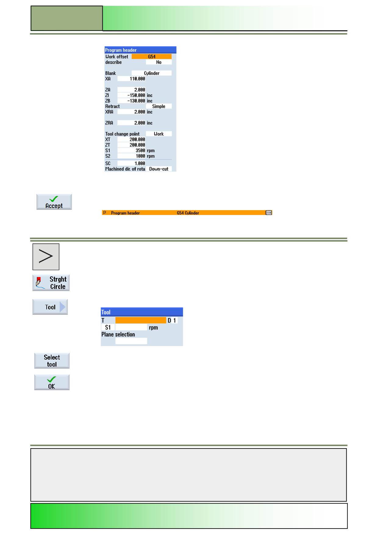
2.
Fill out the program header input mask as follows:
Confirm your inputs by pressing the VSK 8 “Accept“.
The following program block is inserted into the work plan:
3.
Inset now a tool (FINISHING_TOOL_55) into the program.
In order to do this, switch to the horizontal softkey bar 2, by pressing the “Menu extend” key on
the operator panel.
The horizontal softkey bar 2 opens.
Press the HSK 2.2 “Strght Circle” to select the function “Straight Circle”.
The operating area of the function “Straight Circle” opens.
Now press the VSK 1 “Tool” to open the input mask for the tool (see picture below).
In order to insert a tool into the input mask, press the VSK 1 “Select tool”.
Mark the appropriate tool (FINISHING_TOOL_35) with the orange selection cursor and press
the VSK 8 “OK”.
The tool is inserted into the input mask.
Notes
M641
Page 6
828D/840Dsl SINUMERIK Operate
Straight Circle with ShopTurn
M641
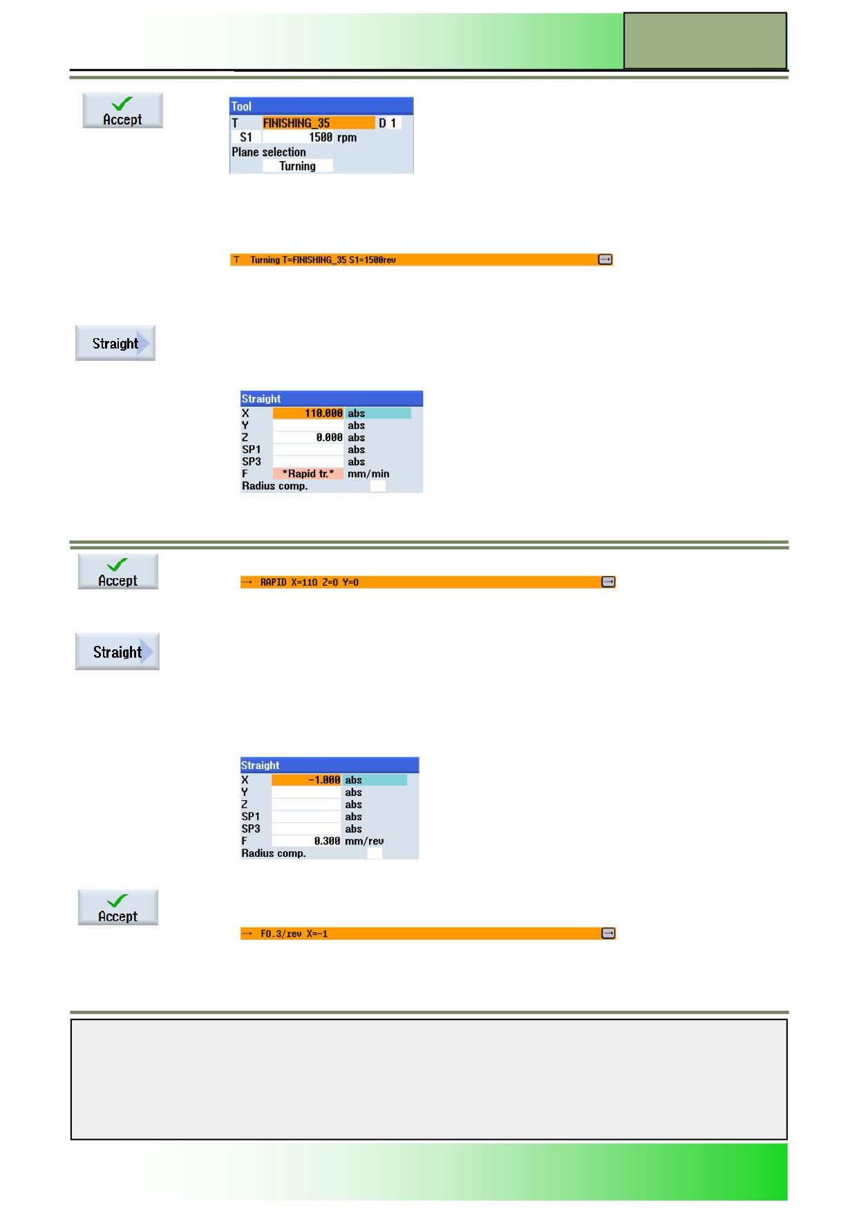
Fill out the rest of the input mask, as follows:
Confirm your inputs by pressing the VSK 8 “Accept”.
The following program block is inserted into the work plan:
4.
Insert now the first “Straight”-cycle into the program, to approach the tool onto the starting posi-
tion for machining.
Press the VSK 2 “Straight”, to open the input mask for the function “Straight”.
5.
Insert the following values into the input mask:
Confirm your inputs by pressing the VSK 8 “Accept”.
The following program block is inserted into the program:
6.
Insert now another “Straight”-cycle into the program.
Press the VSK 2 “Straight”, to open the input mask for the function “Straight”.
7.
Insert the following values into the input mask:
Confirm your inputs by pressing the VSK 8 “Accept”.
The following program block is inserted into the program:
8.
Insert another “Straight”-cycle into the program.
Notes
828D/840Dsl SINUMERIK Operate
Page 7
M641
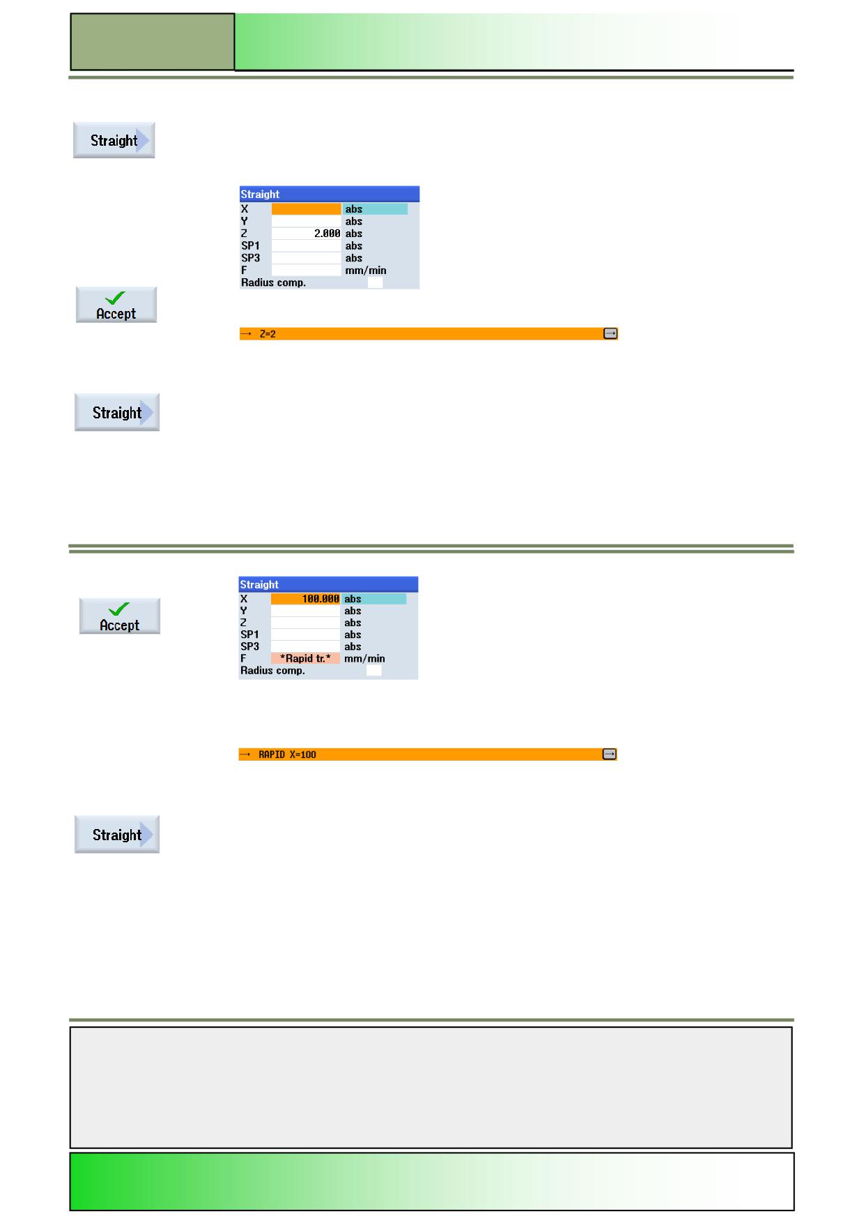
M641
Straight Circle with ShopTurn
8.
Insert another “Straight”-cycle into the program.
Press the VSK 2 “Straight”, to open the input mask for the function “Straight”.
9.
Insert the following values into the input mask:
Confirm your inputs by pressing the VSK 8 “Accept”.
The following program block is inserted into the program:
10.
Insert another “Straight”-cycle into the program.
Press the VSK 2 “Straight”, to open the input mask for the function “Straight”.
11.
Insert the following values into the parameter mask:
Confirm your inputs by pressing the VSK 8 “Accept”.
The following program block is inserted into the program:
12.
Insert now another “Straight”-cycle into the program.
Press the VSK 2 “Straight”, to open the input mask for the function “Straight”.
Notes
M641
Page 8
828D/840Dsl SINUMERIK Operate