SINUMERIK 840D sl. Training. Operate - Turning (2016-2020) - page 21
Operating mode “JOG“
M520
Measuring a tool manually with reference point on the chuck
1.
In the operating mode “JOG“ select the HSK 4 “Meas. Tool” and then the VSK 1 “Manual”.
The “Length manual” window opens.
2.
Press the VSK 4 "Z".
3.
Press the VSK 1 "Select tool”.
4.
After opening the tool list, select the tool that has to be measured.
The cutting edge position and the radius or diameter of the tool must already be entered in
the tool list.
5.
Press the VSK 1 “In manual”.
The selected tool is accepted in the “Length manual” input mask.
6.
Select the cutting edge number “D” and the number of the replacement tool “ST” of the tool.
7.
Put a distance gauge on the chuck, traverse the tool towards the chuck and scratch it.
8.
Press the VSK 7 "Set length".
The tool length is calculated automatically and entered in the tool list. Whereby the cutting edge position and tool radius or
diameter are automatically taken into consideration as well.
Position
Selecting the function “Position“
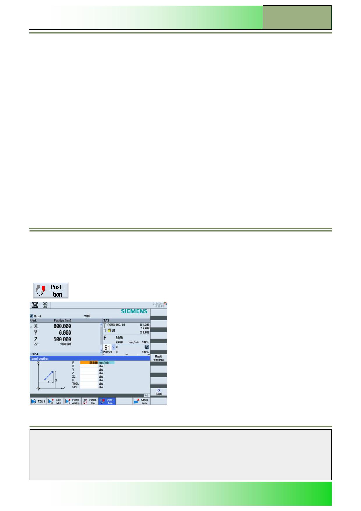
In order to implement simple machining sequences, you can traverse the axes to certain positions in manual mode.
Note:
The feedrate/rapid traverse override is active during traversing.
By pressing the HSK 5 “Position” the input mask “Target position” will be shown on
the screen.
Notes
828D/840Dsl SINUMERIK Operate
Page 21
M520

M520
Operating mode “JOG“
Vertical softkey bar (VSK)
Display area
Description
By pressing the VSK 5 “Rapid traverse” the parameter “F” is set to rapid.
Note:
The VSK 5 “Rapid” can also be pressed if the input field parameter “F” is not the ac-
tive input field (highlighted in orange)
By pressing the VSK 8 “Back” you switch back to the main screen of the Sinumerik
Operate.
Parameters of "Target position"
Parameter
Unit
Description
F
[mm/min]
Feed
[mm/rev]
X
[mm]
Target position [abs/inc]
Y
Note:
Z
The number of the axes is depending on the machine configuration.
Note the machine manufacturer‘s documentation.
Z2
C
[Degree]
Target angle [abs/inc]
TOOL
SP2
Procedure for “Target position“
1.
If required, select a tool.
2.
Select the “JOG” operating mode and press the HSK 5 “Position”.
3.
Enter the target position or target angle for the axis or axes to be traversed.
4.
Specify the desired value for the feedrate “F”.
- OR -
5.
Press VSK 5 "*Rapid traverse*".
*Rapid tr.* is displayed in the input field “F”.
6.
Press the "CYCLE START" button on the machine control panel (MCP).
The axis is traversed to the specified target position.
If target positions were specified for several axes, the axes are traversed simultaneously.
Caution:
Pay attention to a collision free approach of the target position.
Notes
M520
Page 22
828D/840Dsl SINUMERIK Operate
Operating mode “JOG“
M520
Stock removal
Selecting the function “Stock removal”
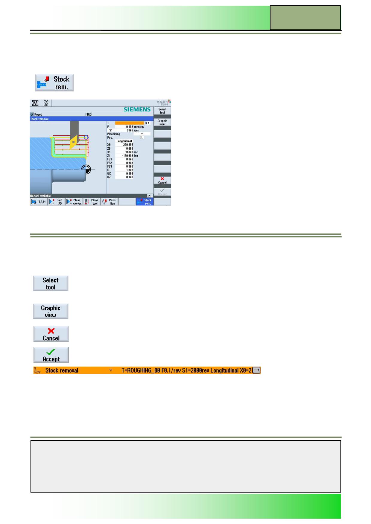
You can use this cycle to face mill any workpiece. A rectangular surface is always machined.
By pressing the HSK 7 “Stock rem.” in the Operating area “Machine” and operating
mode “JOG” the following input mask will be shown on the screen.
Vertical softkey bar (VSK)
Display area
Description
By pressing the VSK 1 „Select tool“ you can insert a tool. Select the desired tool in
the tool list (e.g ROUGHING_80) with the orange selection cursor and press VSK 1
“In manual”
With VSK 2 ”Graphic view” you can switchover between help screen and graphical
view.
By pressing the VSK 7 “Cancel” you can escape the screen “Stock removal”.
With pressing of VSK 8 ”Accept” the following program block is generated:
With “CYCLE START“ the cycle “Stock removal” will be executed.
Notes
828D/840Dsl SINUMERIK Operate
Page 23
M520
M520
Operating mode “JOG“
Parameters of “Stock removal”
Parameter
Unit
Description
T
Tool name
D
Cutting edge number of the tool.
F
[mm/min]
Feed
[mm/tooth]
S
[rpm]
Spindle speed
V
[m/min]
or constant cutting speed
Machining
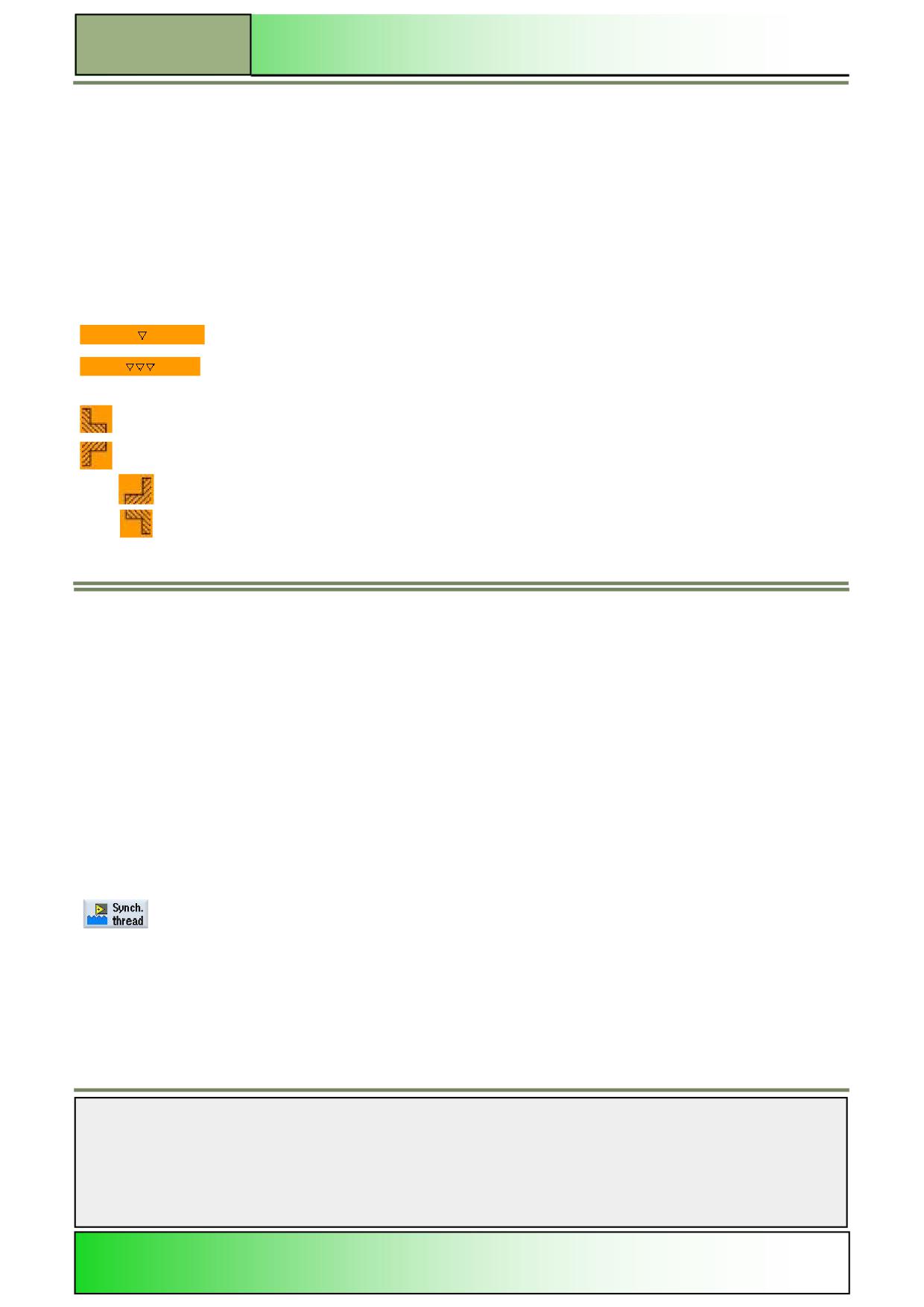
The following machining operations can be selected:
Roughing
Finishing
Machining
Machining positions
X0
Reference point ø (abs)
mm
Z0
Reference point (abs)
X1
End point X ø (abs) or End point X in relation to ø (inc)
mm
End point Z ø (abs) or End point Z in relation to ø (inc)
Z1
FS1..FS3
Chamfer width (FS1...FS3)
Or
mm
or
R1...R3
Rounding radius (R1...R3)
D
mm
Infeed depth (inc) - (for roughing only)
UX
mm
Final machining allowance in X direction (inc) - (for roughing only)
UZ
mm
Final machining allowance in Z direction (inc) - (for roughing only)
Synchronize thread
Selecting the function “Synch. thread”
When a component with a thread has to be re-machined, and the component is placed back into the chuck, the spindle
has to be synchronized with the Z axis so that an angular offset can occur in the thread. This is achieved with the
screen below.
By pressing the HSK 2.5 “Synch. thread” in the extended horizontal softkey bar the
following input mask will be shown on the screen.
Notes
M520
Page 24
828D/840Dsl SINUMERIK Operate
Operating mode “JOG“
M520
Vertical softkey bar (VSK)
The number of softkeys for synchronizing the spindle are available depending on whether there is a counter spindle.
Display area
Description
Geometry axes
By pressing the VSK 6 "Teach main spin." the z-axis is synchronized with main
spindle.
By pressing the VSK 8 “Back” you switch back to the main screen of the Sinumerik
Operate.
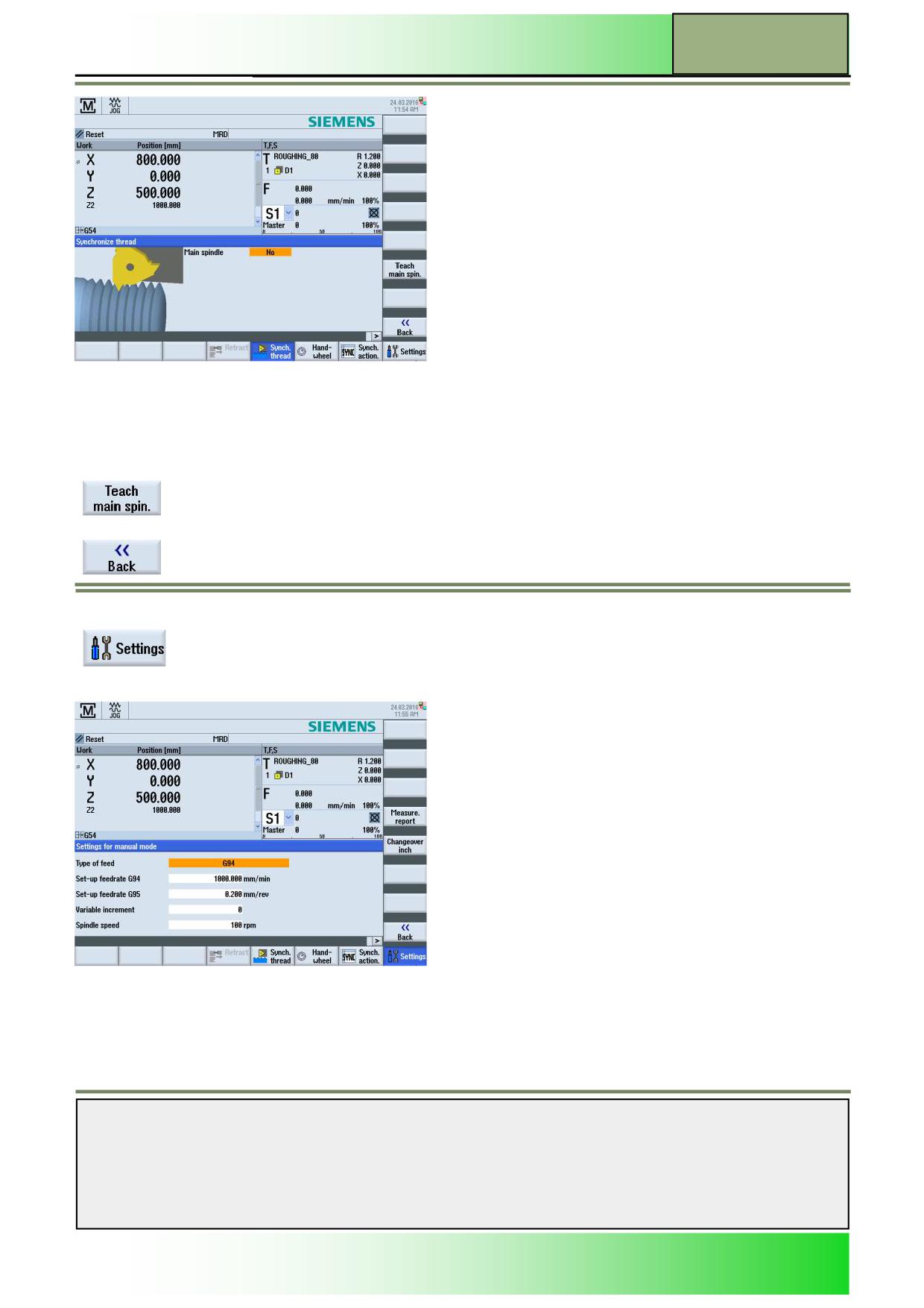
Selecting the function “Settings”
By pressing the HSK 2.8 “Settings” the following input mask will be shown on the screen.
Notes
828D/840Dsl SINUMERIK Operate
Page 25
M520
M520
Operating mode “JOG“
Vertical softkey bar (VSK)
Display area
Description
By pressing the VSK 4 "Measure. report" the settings for the measuring report can be
configured.
By pressing the VSK 5 "Changeover inch" the measuring units are converted from the
metric to the imperial (inch) dimension system. New values have to be entered in inches.
By pressing this key the key function switches to "Changeover metric".
By pressing the VSK 5 "Changeover metric" the measuring units are converted from the
imperial (inch) to the metric dimension system. New values have to be metric. By pressing
this key the key function switches to "Changeover inch".
Accept the selection by pressing the VSK 8 “OK” or
cancel by pressing the VSK 7 “Cancel”.
By pressing the VSK 8 "Back" you switch back to the main screen of the Sinumerik Oper-
ate.
Note:
All Inputs and calculation parameters are converted, as well as positioning displays, tool data (length, radius, wear), zero
point offsets, tool zero point and setting data (workspace limitation).
Settings
Measuring unit [metric/inch]
Regional settings of the units are not being displayed inside the input masks. The following table compares the imperial
system (inch) with the metric system (mm).
Switching between the units is done in the operation area „T,S,M“ in the inputfield “Unit of measure“, or with the HSK 2.8
„Settings“ and VSK "Changeover metric/inch".
Metric
Inch
mm
in
mm/tooth
in/tooth
mm/min
in/min
mm/rev
in/rev
m/min
ft/min
Parameters for "Settings"
In the “Settings for manual mode“ window all configurations for manual operation can be done.
Parameter
Unit
Meaning
Type of feed:
G94
Axis feedrate/linear feedrate
G95
Revolutional feedrate
Setup feedrate G94
mm/
Feedrate in mm/min
min
Setup feedrate G95
mm/rev Feedrate in mm/rev
Variable increment
Enter the desired increment for axis traversal by variable increments
Spindle speed
rpm
Spindle speed in rpm
After inserting the values in the input fields, press the VSK 8 “Back“ to switch back to the main screen of the Sinumerik Op-
erate in the extended view.
M520: END
Notes
M520
Page 26
828D/840Dsl SINUMERIK Operate
M521
Operating mode “MDA”
Sinumerik
Operate
Module Description:
This module describes how a program can be loaded directly from the program manager into the
MDA-buffer and how the processing of the program is started.
It will be explained how an edited program, created in the working window, is written from the MDA-
buffer to any directory on the control unit.
You learn how to create a directory and a workpiece file of the type *.WPD.
Module Objective:
In this module you learn the different options of the operating mode “MDA” in the operat-
ing area “Machine“.
Content:
Operating mode “MDA“
“Load MDI“
“Save MDI“
This document was produced for training purposes.
828D/840Dsl SINUMERIK Operate v4.7
Page 1
M521
Siemens assumes no responsibility for its contents.
M521
M521
Page 2
828D/840Dsl SINUMERIK Operate
Operating mode “MDA”
M521
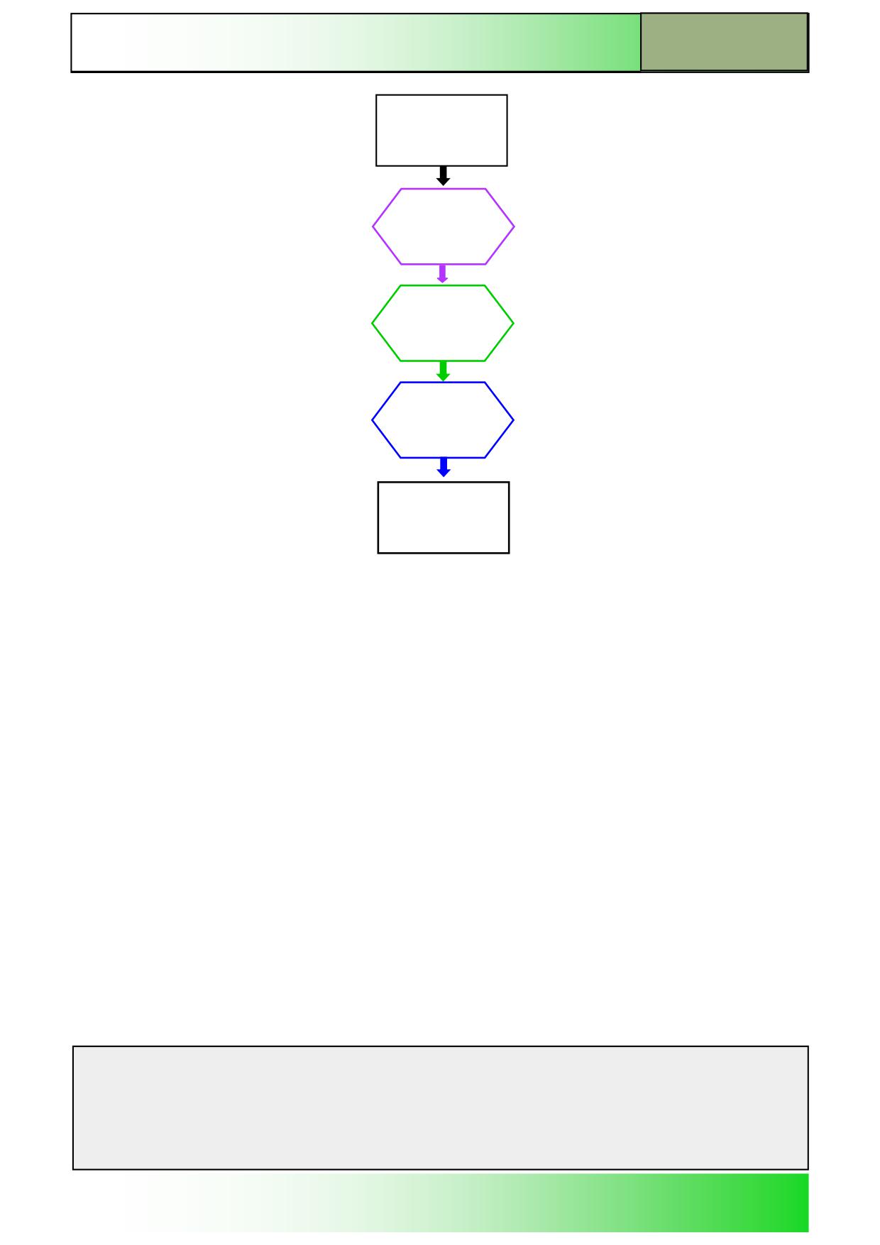
Operating mode
"MDA":
START
Operating
mode “MDA“
“Load MDI“
“Save MDI“
Operating mode
"MDA":
END
Notes
828D/840Dsl SINUMERIK Operate
Page 3
M521
M521
Operating mode “MDA”
Operating mode “MDA“
In "MDA" mode (Manual Data Automatic), you can enter G-code commands block-by-block and immediately execute them
for setting up the machine.
You can load an MDA program straight from the Program Manager into the MDA buffer. You may also store programs
which were rendered or changed in the MDA operating window into any directory of the program manager.
Selecting the operating mode “MDA“
The operating mode “MDA“ can be selected as follows:
Press the “MDA”-key on the operator panel (OP).
The operating mode “MDA“ will be opened
immediately.
- OR -
Press the “MENU SELECT”-key on the operator panel.
Press the VSK 2 “MDA“ in the yellow vertical softkey bar on the right side of the screen and the
operating mode “MDA” will be opened immediately.
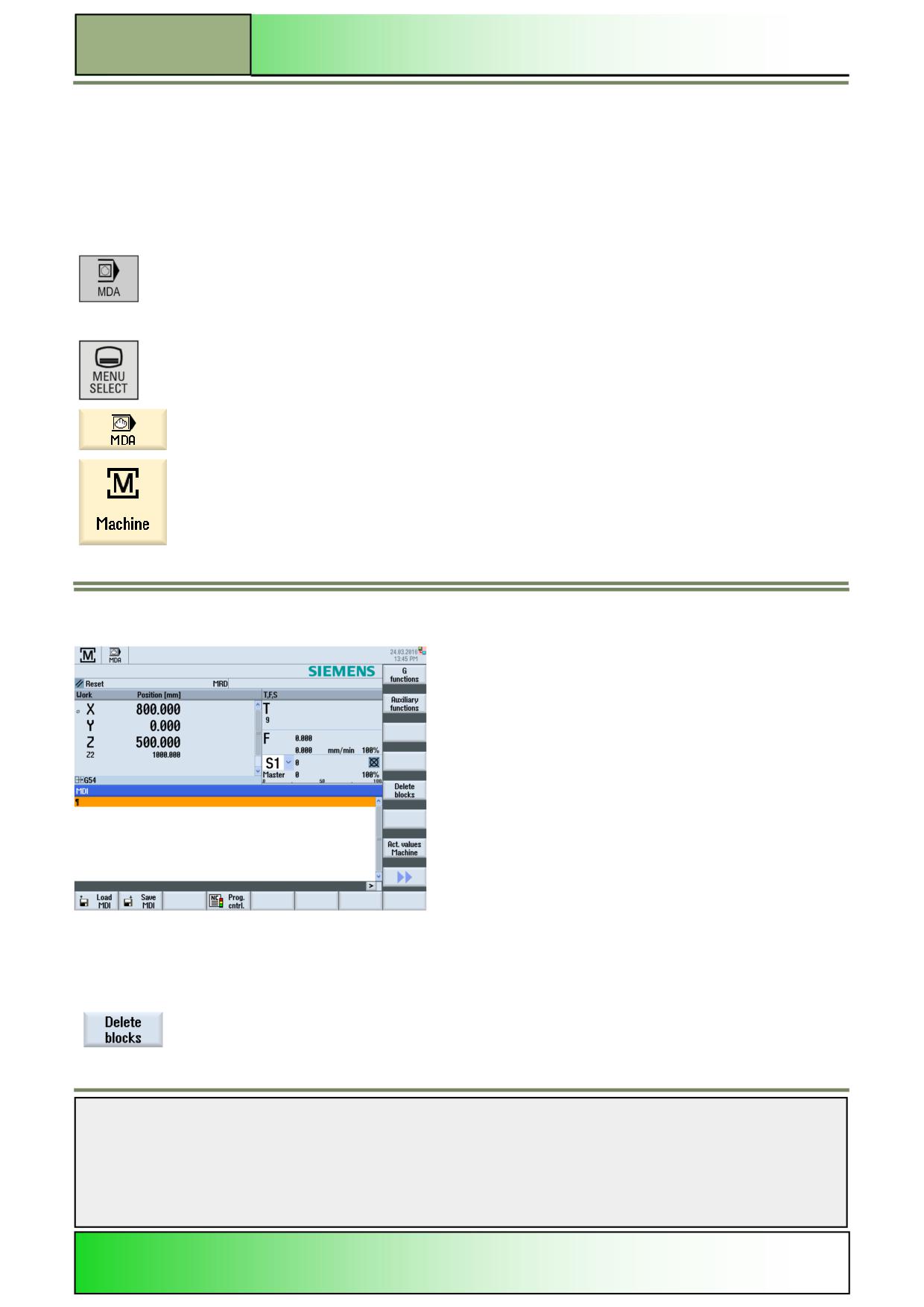
Now switch to the operating area “Machine” by pressing the “MACHINE” key on the operator
panel or on the keyboard or press the “MENU SELECT“-key on the operator panel and the
yellow HSK 1 “Machine“. The following screen opens:
In the operating mode “MDA“ the following softkeys are shown in the horizontal and vertical softkey bar of the Sinumerik
Operate:
Vertical softkey bar
Display area
Description
By pressing the VSK 1.5 “Delete blocks” entered program blocks can be deleted.
Notes
M521
Page 4
828D/840Dsl SINUMERIK Operate
Operating mode “MDA”
M521
Horizontal softkey bar 1
Display area
Description
By pressing the HSK 1 “Load MDI” the “Load into MDI” with the program manager window
opens.
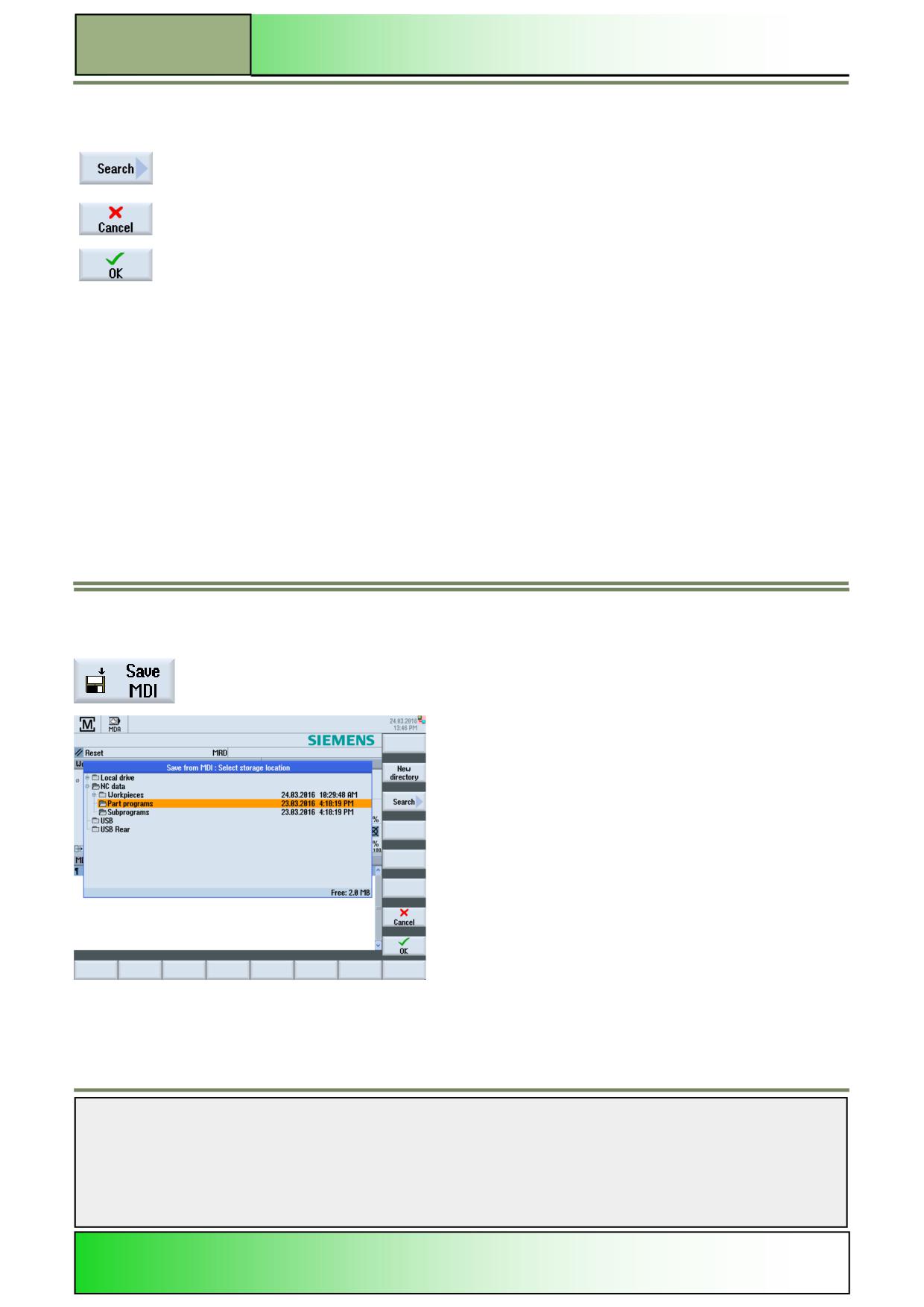
By pressing the HSK 2 “Save MDI” the “Save from MDI : Select storage location” with the
program manager window opens.
“Load MDI“
Selecting the function “Load MDI”
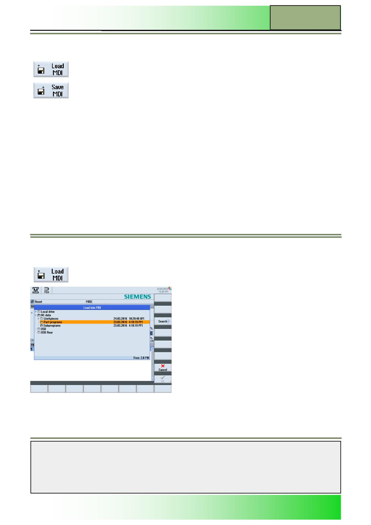
By pressing the HSK1 “Load MDI” the “Load into MDI” window with the Program Manger is
displayed as below:
To navigate in the program manager window use the blue cursor-keys
The following operation options are available in the vertical softkey bar to the right:
Notes
828D/840Dsl SINUMERIK Operate
Page 5
M521
M521
Operating mode “MDA”
Vertical softkey bar
Display area
Description
Press the VSK 3 “Search“ to open the “Find file” window.
Press the VSK 7 “Cancel“ to close the “Load into MDI” window.
By pressing the VSK 8 “OK” the marked program will be opened after closing the window
“Load into MDI” and taken over in the MDI-window.
If a program is already in the MDI-buffer, you will be asked to overwrite. Accept with “OK” or
refuse with “Cancel”. A program loaded in the MDI-buffer can be edited or can be executed by
pressing the “CYCLE START“-button on the MCP
Loading a MDI-program
1.
Switch to operating mode “MDA“ (see section 2.1).
2.
Press the VSK 1 “Load MDA”.
The “Load into MDI” Program manger window opens.
3.
Mark the program you want to load with the orange cursor-keys.
4
Press the VSK 8 “OK“.
The window closes and the program is ready for machining.
“Save MDI“
Selecting the function “Save MDI”
By pressing the HSK2 “Save MDI” the “Save from MDI : Select storage location” window with
the Program Manger is displayed as below:
Navigate through the program manager window by means of the blue cursor-keys.
The following softkeys are available in the vertical softkey bar.
Notes
M521
Page 6
828D/840Dsl SINUMERIK Operate
Operating mode “MDA”
M521
Vertical softkey bar
Display area
Description
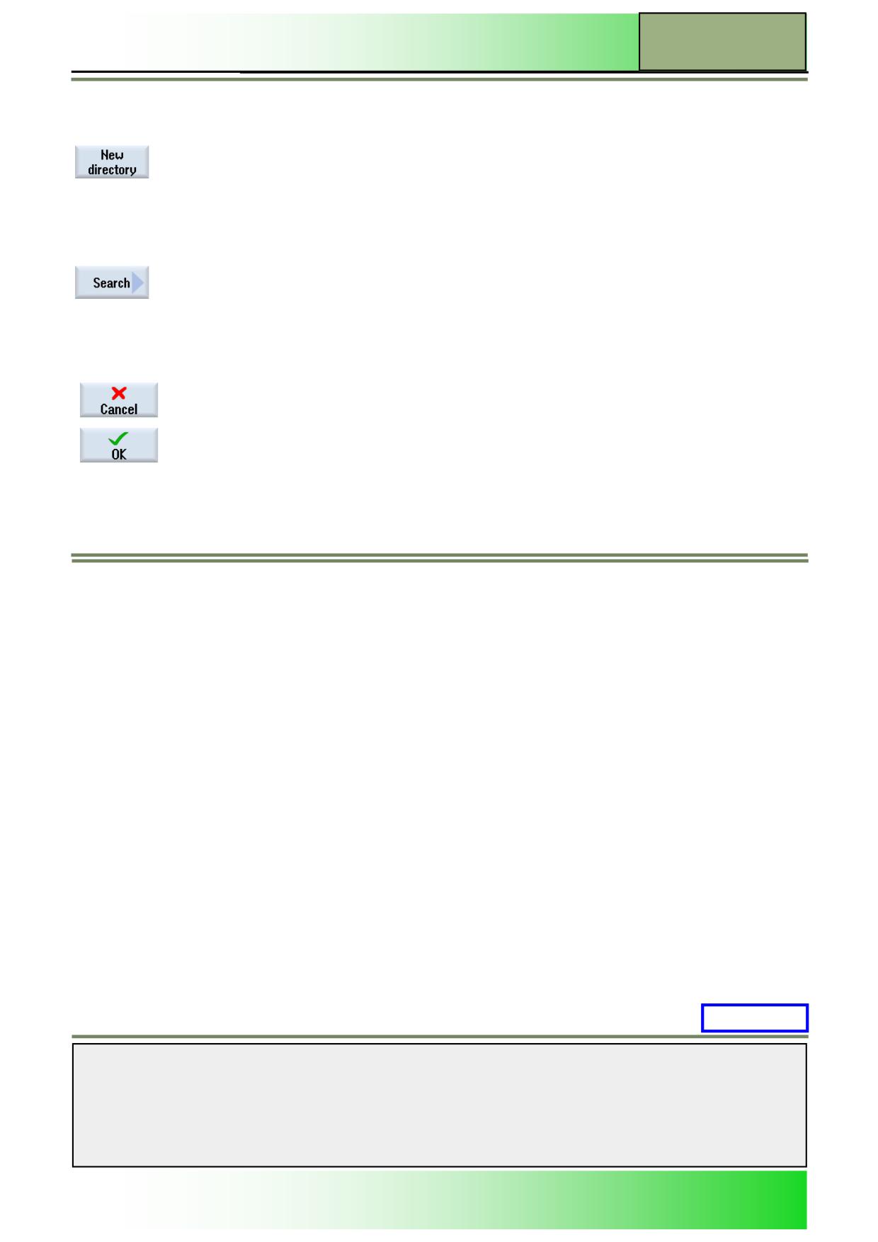
By pressing the VSK 1 “New directory“ a new directory can be created in the “Local drive” fold-
er.
An input window opens where a name can be entered for the new directory that is to be created.
Create a new directory by pressing the VSK 8 “OK” or abort with pressing the VSK 7 “Cancel”.
The “New directory”-softkey is not active if you have placed the cursor on or in the “NC data”
directory.
Press the VSK 3 “Search“ to open the “Find file” window.
Display area
Description (continuation)
By pressing the VSK 7 “Cancel” the “Save from MDI” window will be closed without saving.
By pressing the VSK 8 “OK”, with the cursor on a folder, the “New G code program” window
opens. Select the file type (Main program: MPF/Subprogram: SPF) that you wish to create.
After input of the filename the program will be written from the MDI-buffer to the new created
file or the file that is marked with the cursor.
Saving a MDI-program
1.
Select the operating mode “MDA” (see section 2.1)
The “MDI” editor opens.
2.
Create the MDI program by entering the G-code commands using the keyboard.
3.
Press the VSK 2 "Save MDI”.
The "Save from MDA : Select storage location" window opens. It shows you a view of the program
manager.
4.
Select the drive to which you want to save the MDI program you have created, and place the cursor on
the directory in which the program is to be stored.
5.
Press the VSK 8 “OK“.
Note:
When you place the cursor on a folder, a window opens which prompts you to assign a program name.
When you place the cursor on a program, you are asked whether the file should be overwritten or not.
7.
Enter a name for the program and press the VSK 8 “OK“.
The program will be saved under the specified name in the selected
directory.
M521: END
Notes
828D/840Dsl SINUMERIK Operate
Page 7
M521

M521
Operating mode “MDA”
Notes
M521
Page 8
828D/840Dsl SINUMERIK Operate
M523
Operating area “Parameter”
Sinumerik
Operate
Module Description:
In the tool management area all tool data relevant for machining (e.g., tool length, radius correction,
tool wear and magazine configuration) can be viewed and modified.
The tool management contains the following sub-functions:
the tool list
the tool wear
the magazine management
In addition to these sub-functions a machine specific list can be configured by the machine manufac-
turer. Refer to the machine manufacturers documentation.
In the "Work offset" menu the linear and rotational offsets can be viewed and modified in the settable
work offset (WO).
Module Objective:
In this module you learn to use the tool management with the Sinumerik Operate. You
learn about the programming philosophy of the adjustable and programmable work off-
set, the function of the user variables and how to modify the “working area limitation”.
Content:
Operating area “Parameter“
Tool list
Tool wear
Zero offset basics
Work offset
This document was produced for training purposes.
828D/840Dsl SINUMERIK Operate v4.7
Page 1
M523
Siemens assumes no responsibility for its contents.
M523
M523
Page 2
828D/840Dsl SINUMERIK Operate

Operating area “Parameter”
M523
Operating area
"Parameter":
START
Operating
area
“Parameter“
Tool list
Tool wear
Zero offset
basics
Work offset
Operating area
"Parameter":
END
Notes
828D/840Dsl SINUMERIK Operate
Page 3
M523
M523
Operating area “Parameter”
Operating area “Parameter“
Selecting the operating area “Parameter”
In the Operation area “Parameter” you have a choice of selecting between various lists (e.g. Tool list, tool wear, magazine
list, offsets, user variables and setting data). For example in the tool management area, all tools and if configured also the
magazine locations are being displayed. Both lists display the same tools in the same order. When switching between lists,
the position of the cursor on a particular tool in the current screen is carried over to the same tool in a new screen. The lists
differ from each other by the displayed parameters and the Softkey functions.
Switching between lists is a specific change from one topic to the next.
Tool list: All parameters and functions required to create and set up tools are displayed.
Tool wear: All parameters and functions that are required during operation, e.g. wear and monitoring functions, are
listed here.
Magazine: Magazine and magazine location-related parameters and functions for the tools and magazine locations are
listed here.
The operating area “Parameter“ can be opened from every operating modes (“JOG”, “MDA”, “AUTO”).
Press the “OFFSET”-key on the keyboard.
The operating area “Parameter“ respectively the “Tool list” opens directly.
- OR -
Press the “MENU SELECT“-key on the operator panel. The yellow horizontal and vertical soft-
key bar opens.
Then switch to the operating area “Parameter” by pressing the HSK 2 “Parameter” on the oper-
ator panel.
The operating area “Parameter” opens, with the “Tool list”, “Tool wear”, “Magazine”, “Work
offset”, “User variables” and the “Setting data”.
These functions are made available in the following described horizontal softkey bar.
Horizontal softkey bar (HSK)
Display area
Description
By pressing the HSK 1 “Tool list” the tool list window opens.
By pressing the HSK 2 “Tool wear“ the tool wear list opens.
Notes
M523
Page 4
828D/840Dsl SINUMERIK Operate
Operating area “Parameter”
M523
Display area
Description (continuation)
By pressing the HSK 4 “Magazine“ the Magazine management is opened.
By pressing the HSK 5 “Work offset“ a list with all Work offsets is opened.
By pressing the HSK 6 “User variable“ a list with all R variables is opened.
By pressing the HSK 8 “Setting data” a list with all setting data is opened.
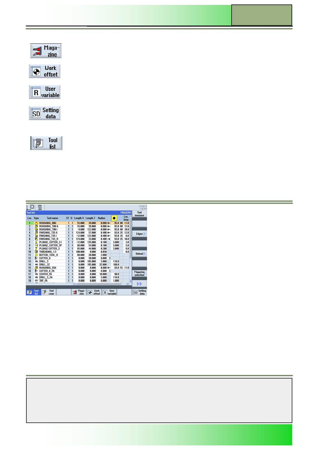
Selecting the “Tool list”
By pressing the HSK 1 “Tool list“ the “Tool list“ window opens.
(Note the screen below.)
In the tool list all parameters and functions that are required to create and set up the tools are displayed, regardless weather
the tools are assigned or not assigned to a magazine location. Each tool is uniquely identified by the location number, the
tool name and the replacement tool number.
The most common tools and probes for turning, drilling and milling are offered in the tool list.
Geometrical and technological tool data can be assigned to each tool type.
Notes
828D/840Dsl SINUMERIK Operate
Page 5
M523
M523
Operating area “Parameter”
Vertical softkey bar
Display area
Description
By pressing the VSK 1.1 “Tool measure” the “Measuring tool” window opens.
By pressing the VSK 1.2 “New tool” a new tool can be created. This function is only availa-
ble, if the cursor is positioned on a filed that does not yet has a tool assigned to it.
By pressing the VSK 1.3 “Edges” the vertical softkey bar for assigning new cutting edges and
deleting existing cutting edges opens to the right side of the screen. If a tool has several cut-
ting edges each edge gets its own set of correction data.
By pressing the VSK 1.4 “Further data” more information about a tool will be displayed. This
function is only available for tools which have additional information.
By pressing the VSKs 1.5 ”Unload” or “Load” the actual selected tool wil be unloaded from or
loaded to the magazine. Unloaded tools are being displayed on the bottom of the magazine
list.
By pressing the VSK 1.6 “Delete tool” the selected tool will be deleted from the tool list.
By pressing the VSK 1.7 “Magazine selection” Softkey multiple times you can jump between
buffer location (spindle and gripper), Magazine and NC-memory (unloaded tools) and back to
the buffer location. The cursor is always positioned at the beginning of each group.
By pressing the VSK 1.8 “Extend” on the operator panel the extended vertical softkey bar 2
opens on the right hand side of the screen.
By pressing the VSK 2.1 “Sort” you can sort the tools in the tool list according to the following
criteria:
Magazine
Name
Type
T-Number
The suitable softkeys are offered in the vertical softkey bar.
Display area
Description (continuation)
Pressing the VSK 2.2 “Filter” opens the screen to set the filter options.
Pressing the VSK 2.3 “Search“ opens a new softkey bar with the functions
Tool
Magazine location
Empty location
The type of search is selected by the sotfkey selection.
Pressing the VSK 2.4 „Details“ opens a new softkey bar with the functions
Tool Data
Cutting edge data
Monitoring data
The details of the tool which is selected by the cursor position are listed in the screen.
Pressing the VSK 2.8 “Back“ on the operator panel you switch back to the vertical softkey bar
1.
Notes
M523
Page 6
828D/840Dsl SINUMERIK Operate
Operating area “Parameter”
M523
Tool parameters
Column header
Meaning
Loc.
Magazine/location number
Magazine number:
If more than one magazine is available, first the location number and then the magazine
number is displayed separated by a slash. E.g.:
Location number 1 in magazine 1
Location number 1 in magazine 2
Tools in the tool list not assigned to a magazine are displayed without a location number at
the end of the window.
You can manage tools that are not changed automatically, by hands (hand tools).
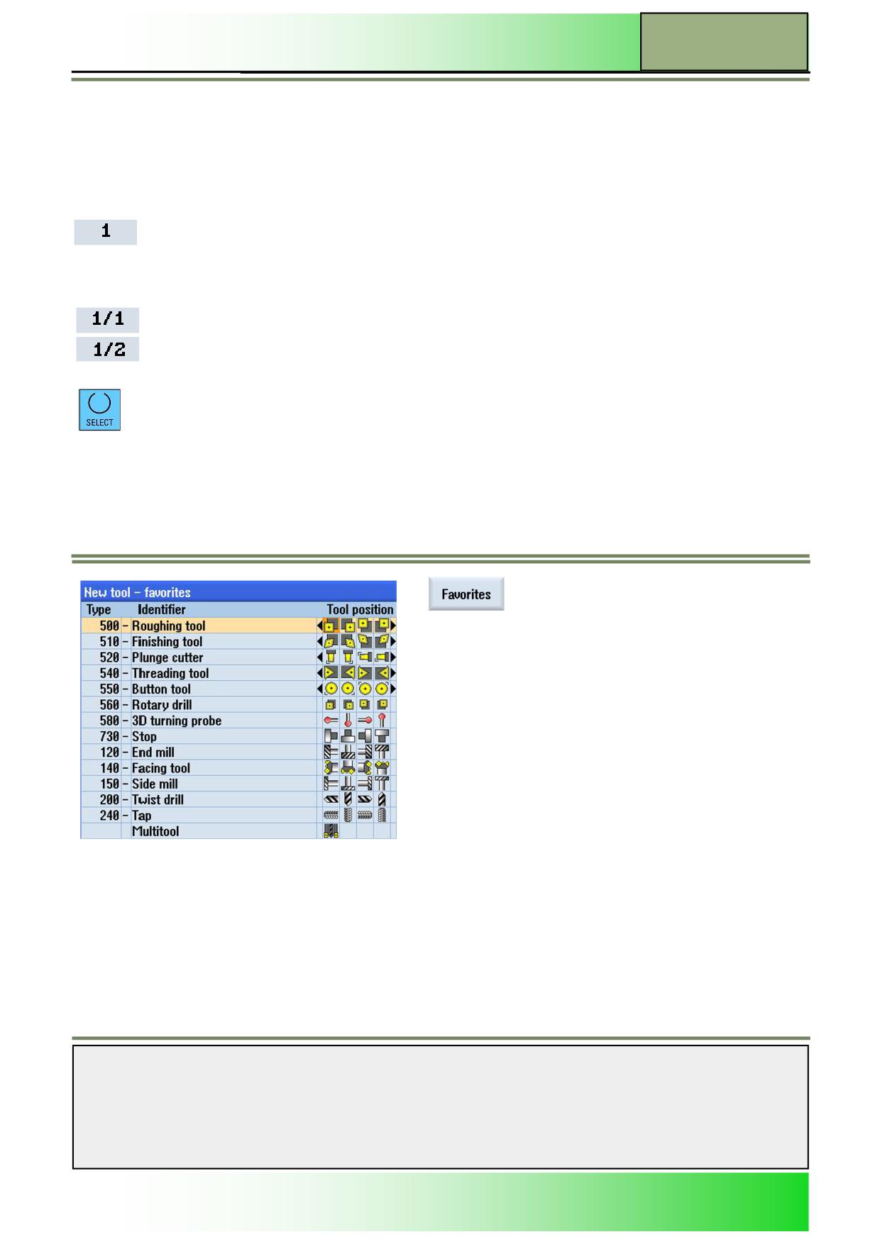
If the orange selection cursor is placed in the type
field on a tool icon you can change the tool type by pressing the “SELECT”-key.
Type
Tool type
Tools can be created on a free tool position or by pressing the VSK 1.2 “New tool” in the tool list. The following tool win-
dows can be opened by pressing the corresponding vertical softkeys.
Press the VSK 1 “Favourites” to open the “New tool - favour-
ites” list. In the favourite list
the most often used tools are saved as favourites for a fast
access.
Notes
828D/840Dsl SINUMERIK Operate
Page 7
M523
M523
Operating area “Parameter”
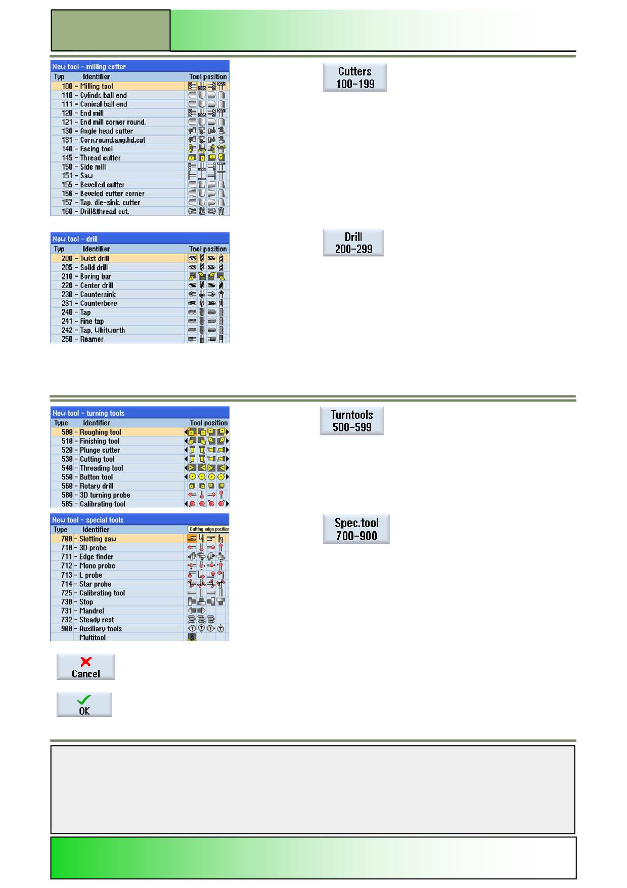
Press the VSK 2 “Cutters 100-199” to open the “New tool -
milling cutter” list.
A list of all available milling cutters opens.
Press the VSK 3 “Drill 200-299” to open the “New tool -
drill” list.
A list with all available
Drilling tools opens.
Press the VSK 4 “Turntools 500-599” to open the “New
tool - turning tools” list.
A list with all available
Turning tools opens.
Press the VSK 5 “Spec.tool 700-900” to open the “New tool
- special tools” list.
A list with all special tools opens.
Press the VSK 7 “Cancel” to reject the tool selection and to jump back to the “Tool list” window in
the operating area “Parameter”.
Press the VSK 8 “OK“ to accept the selected tool and to jump back to the “Tool list” window in
the operating area “Parameter”.
The selected tool will be loaded into the tool list
Notes
M523
Page 8
828D/840Dsl SINUMERIK Operate

Operating area “Parameter”
M523
Column header
Meaning (continuation)
Tool name
Name of the tool:
To identify a tool you can enter a tool name as text
or a T-number. If a new tool is created, tool names are pre-assigned as default.
ST
Replacement tool number:
(for replacement tool strategy) As default “1” is being entered here. If a new tool with the same
name, as a already existing tool, is being created, then the new tool gets the Index “2”. This way
it is possible to define a replacement tool.
D
Cutting edge number:
For tools with multiple cutting edges, each tool receives it’s own correction data field. Up to 9
edges per tool can be managed. The max. Number depends upon the control configuration.
Length X/Z
Tool length:
Geometry length of the tool in X and Z direction.
Radius/diameter
Tool radius/diameter
Radius of the cutting edge in case of turning tools Type 500 - 560
Radius or diameter in case of rotating tools
Radius or diameter of the ball in case of probes type 580 and 711
Reference direction
Holder angle for roughing and finishing tools
The reference direction for the holder angle specifies the cut direction.
N
Number of teeth:
for all milling tools
with the exception of saw type 151
Holder angle
Holder angle of turning tools for
Roughing tool type 500
Finishing tool type 510
(refer to the cutting tip angle)
Width
Width of
Side mill type 150
Saw type 151
Loc width
Width of the cutting edge of
Plunge cutter type 520
Cutting tool type 530
Tip angle or Pitch
Tip angle for
Type 200 - twist drill
Type 220 - center drill
Type 230 - countersink
Pitch for
Type 240 - tap
Notes
828D/840Dsl SINUMERIK Operate
Page 9
M523
M523
Operating area “Parameter”
Column header
Meaning (continuation)
Drill rad.
Drill radius for
Rotary drill type 560
(Holder angle and cutting edge angle are set by default settings)
Cutting edge angle
Cuttting edge angle for turning tools
Roughing tools type 500
Finishing tools type 510
(refer to holder angle)
Loc. len
Tip length for
Roughing tools type 500
Finishing tools type 510
Plunge cutter type 520
The tip length is required for displaying the tools during the simulation of the program processing.
Direction of spindle rotation
Turning tools and non-driven tools:
direction of the main spindle
Powered tools for milling and boring:
direction of the tool spindle
Coolant 1 and 2 can be switched off and switched on.
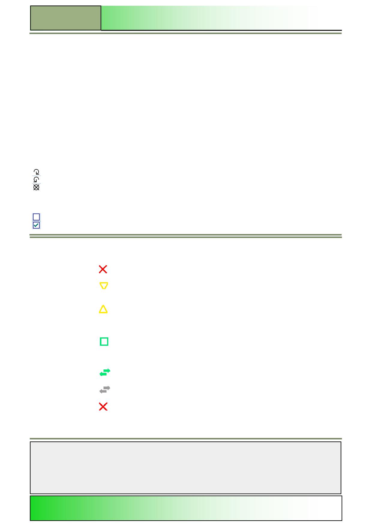
Icons in the toolbar and their meaning
Icons
Meaning
Red X
The tool is disabled
Yellow triangle pointing
The pre-warning limit has been reached
downward
Yellow triangle pointing
The tool is in a special state
upward
Place the cursor on the marked tool. A tool tip will provide a brief description
Green frame
The tool is preselected.
Magazine/location number:
Green double arrow
The magazine location is positioned at the change position
Gray double arrow
The magazine location is positioned at the loading position
Red X
The magazine location is disabled
Notes
M523
Page 10
828D/840Dsl SINUMERIK Operate
Operating area “Parameter”
M523
Tool wear
Selecting the function “Tool wear“
All parameters and functions that are required during operation are contained in the tool wear list.
Tools that are in use for long periods are subject to wear. You can measure this wear and enter it in the tool wear list. The
Sinumerik Operate then takes this information into account when calculating the tool length or radius compensation.
This ensures a consistent level of accuracy during workpiece machining.
You can automatically monitor the tools' working times via the workpiece count, tool life or wear.
In addition, you can disable tools when you no longer wish to use them.
Note:
Depending on the control configuration, the input of the tool wear can be additive. Please refer to the machine tool manu-
facturer documentation.
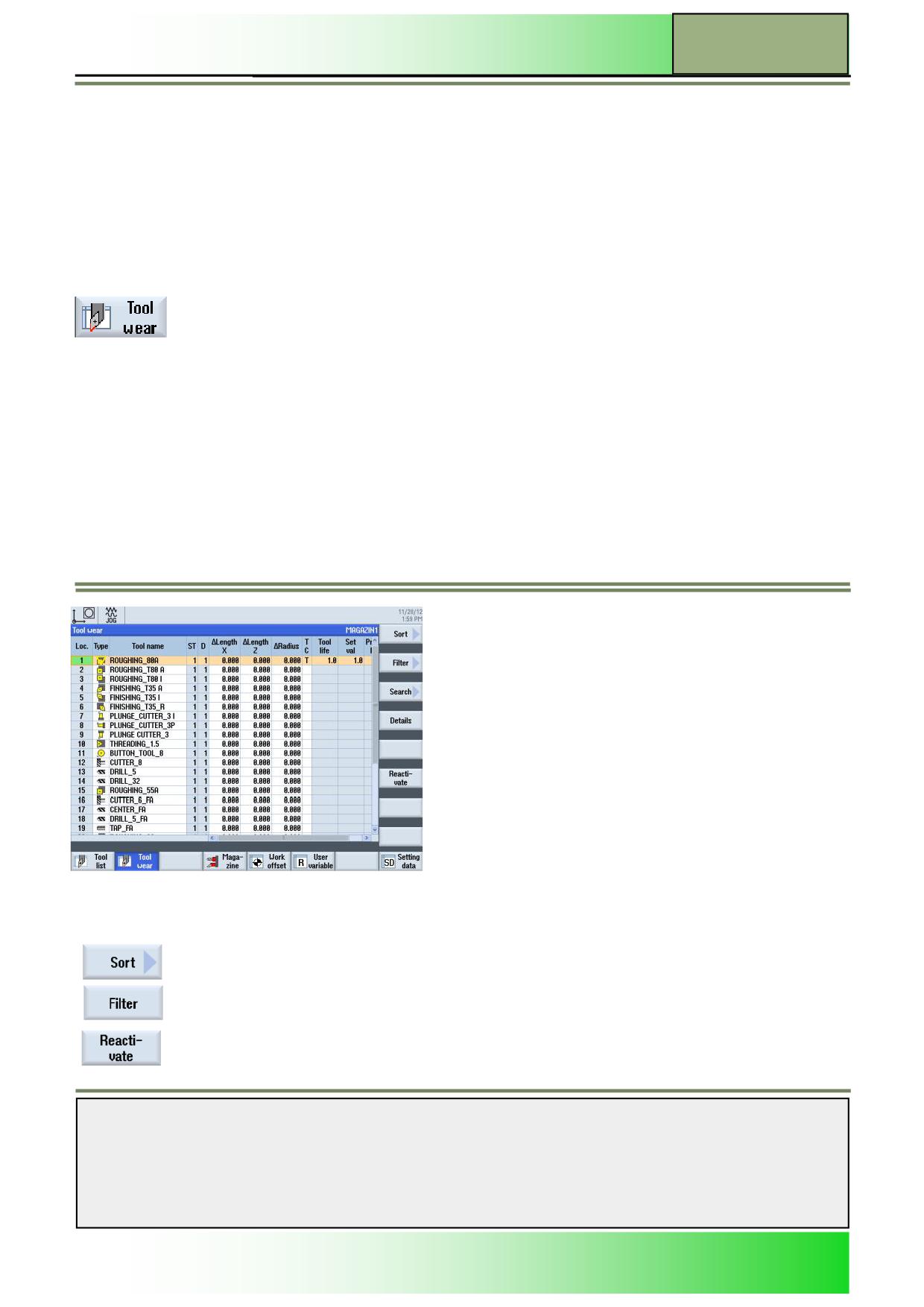
By pressing the HSK 2 “Tool wear“ the “Tool wear” screen input mask opens.
Vertical softkey bar
Display area
Description
By pressing the VSK 1 “Sort” and “Filter” you can sort and filter the tools in the tool list ac-
cording to different parameters.
By pressing the VSK 6 “Reactivate“ locked tools, and tools that have reached their pre-
warning limit can be made operational again.
Notes
828D/840Dsl SINUMERIK Operate
Page 11
M523

M523
Operating area “Parameter”
Parameters for “Tool wear”
Parameter
Meaning
Location
Magazine/location number:
Type
Tool type:
Tool name
Tool name:
ST
Replacement tool number:
D
Cutting edge number
ΔLength X
Wear of length in X direction and Z direction
ΔLength Z
are entered in these fields.
ΔRadius
Radius wear
The Sinumerik Operate checks the entered values
whether they exceed an absolute or incremental threshold or not.
The incremental threshold is the maximum difference between present wear and new wear.
The absolute threshold is the maximum total wear value that can be entered.
Note:
Please refer to the machine manufacturer's specifications.
T
Tool monitoring by tool life:
With the tool life T (Time), the service life for tool with machining federate is monitored in
minutes.
Tool monitoring by count
C
With the count C, the number of workpieces machined by the tool is counted.
Tool monitoring by wear
With wear W, the greatest value in the wear parameters ΔLength X, ΔLength Z, ΔRadius or
W*
ΔØ in the wear list is monitored.
* The wear monitoring is configured via a machine data item.
Note:
Please refer to the machine manufacturer's instructions.
Notes
M523
Page 12
828D/840Dsl SINUMERIK Operate

Operating area “Parameter”
M523
Parameter
Meaning (continuation)
Tool life (T)
Tool life
Quantity (C)
Number of workpieces
Wear (W)
Tool wear
The wear monitoring is configured via a machine data item. Please refer to the machine manu-
facturer`s instructions.
Set val
Setpoint value for tool life, workpiece count, or wear.
Prewar limit
Prewarning limit:
Specification of the tool life, workpiece count or wear at which a warning is displayed.
Note:
If the adjusted rest life of the tool, the number of changes or the wear is reached, the tool will be
disabled.
This tool will not be selected for the next tool change.
If present, an adequate sister tool will be used instead.
The monitoring refers in each case to the selected cutting edge.
It is possible to reactivate a disabled tool.
D
Single tools can also be disabled by hand, if these tools are not in use anymore or if the tools life
ran off.
(The tool is disabled if the checkbox is activated).
Icons in the tool wear list and their meaning
(See section Tool List, Icons in the tool list, in this module)
Entering the tool wear or disabling a tool
1.
Press the “MENU SELECT“-key on the operator panel, then the HSK 2 “Parameter” and the
HSK 2 “Tool wear” to switch to the tool wear list.
2.
Enter values for length, radius, setpoint, prewarning and tool life.
- OR -
2.
Activate the “D”-parameter checkbox for disabling the tool manually.
Sort and Filter
For the functions “Sort” and “Filter” in the tool list refer to the section 3 in this module.
Reactivating a tool
You can replace disabled tools or make them ready for reuse.
Prerequisite is, that the monitoring function must be active and a setpoint is stored.
1.
Press the “MENU SELECT“-key on the operator panel, then the HSK 2 “Parameter” and the
HSK 2 “Tool wear” to switch to the tool wear list.
2.
Position the cursor on the disabled tool which you would like to reuse.
Press the VSK 6 "Reactivate".
The value entered as the setpoint is entered as the new tool life workpiece count.
The disabled tool is active again.
Notes
828D/840Dsl SINUMERIK Operate
Page 13
M523
M523
Operating area “Parameter”
Reactivating and positioning
When the "Reactivate with positioning" function is configured, the selected tool's magazine location will also be positioned at
a loading point.
You can exchange the tool.
Reactivation of all monitoring types
When the "Reactivation of all monitoring types" function is configured, all the monitoring types set in the NC for a tool are
reset during reactivation.
Note:
Refer to the machine manufacturer‘s specifications.
Zero offset basics
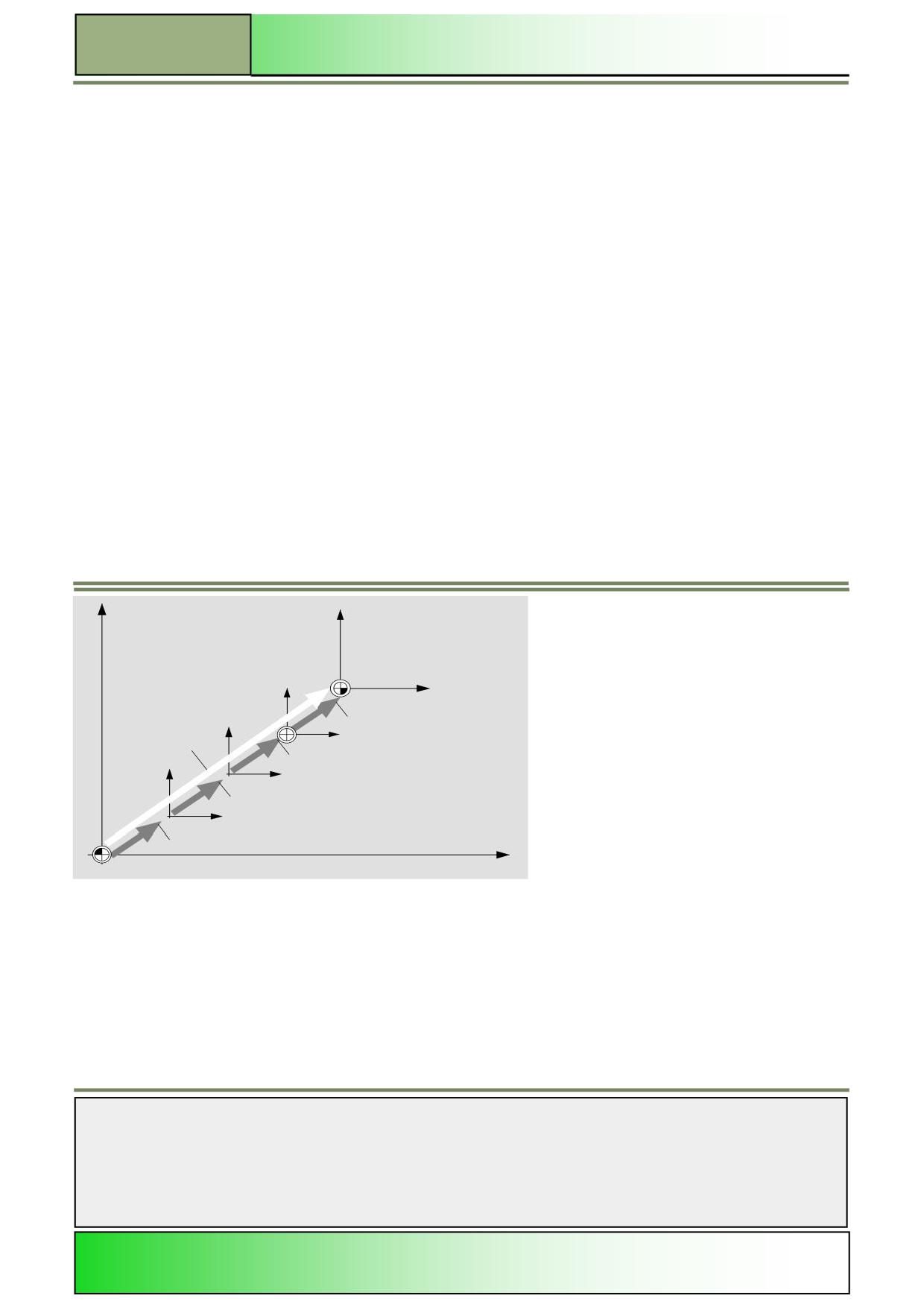
Following reference point approach, the actual value display for the axis coordinates is based on the machine zero (M) of
the machine coordinate system (MCS ). The program for machining the workpiece, however, is based on the workpiece
zero (W) of the workpiece coordinate system (WCS ).
The machine zero and workpiece zero are not necessarily identical.
The distance between the machine zero and workpiece vary in
accordance with the type of tool and the way it is clamped. This zero offset is taken into account during execution of the
program and can be a combination of different offsets.
On the Sinumerik Operate, the position actual value display refers to the SZS-coordinate system (settable zero system).
The position of the active tool relative to the workpiece zero is displayed. The offsets are added as follows:
W
WCS
Transformation of coordi-
Tool offset
SZS
Work offset fine
Work offset coarse
Base offset
MCS
M
Base offset
The base offset is a zero offset that is always active. If you have not defined a base offset, its
value will be zero. You determine the base offset via "Measure workpiece zero” .
See Module B570 - ”Operating mode JOG”, in Sinumerik Operate section “Set Work offset” and
“Measure workpiece zero”.
Every zero offset (G54 to G57, G505 to G599) consists of a coarse offset and a fine offset. You
can call the work offsets from any sequence program (coarse and fine offsets are added to-
Zero offsets
gether).
You can save the workpiece zero, for example, in the coarse offset,
and then store the offset that occurs when a new workpiece is clamped between the old and
the new workpiece zero in the fine offset.
Notes
M523
Page 14
828D/840Dsl SINUMERIK Operate
Operating area “Parameter”
M523
Fine offsets must be set up by the machine manufacturer.
Note:
Also refer to the machine manufacturer's instructions.
You always program coordinate transformations for a specific sequence program.
Coordinate
They are defined by:
transformations:
Offset
Rotation
Scaling
Mirroring
These transformations can work as “new” or they can work “additive” to the active zero point
offset.
Total offset:
The total offset is calculated from the sum of all offsets and coordinate transformations.
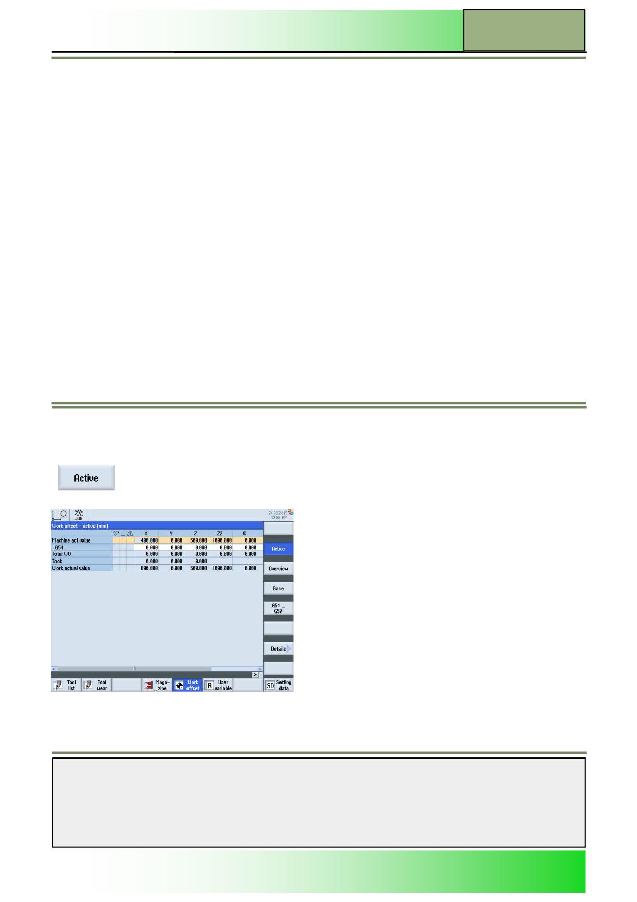
Work offset
Active work offset
The following work offsets are displayed in the “Work offset - active” window:
Work offsets, for which offsets are included, or for which values are entered
Adjustable work offsets
Total work offset
This window is generally used only for monitoring. The availability of the offsets depends on the setting. Please refer to the
manufacturer's documentation.
Selecting the function “Active”
By pressing the VSK 2 “Active“ the “Work offset - active” window opens.
Notes
828D/840Dsl SINUMERIK Operate
Page 15
M523
M523
Operating area “Parameter”
Work offset overview
In the “Work offset - Overview” window, all active offsets and system offsets are displayed for all set-up axes.
In addition to the offset, the rotation, scaling and mirroring defined using this are also displayed.
This window is generally used for monitoring.
Settable zero offset
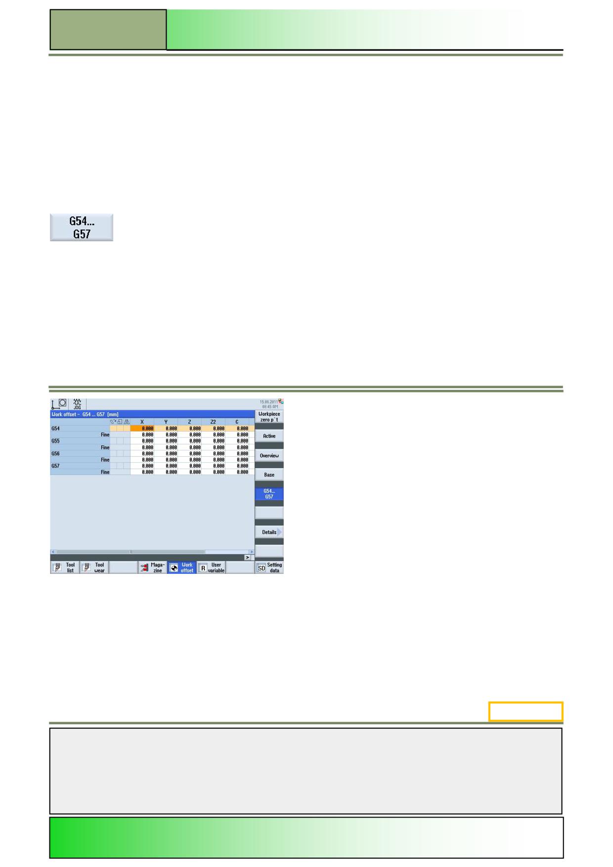
All settable offsets, divided into coarse and fine offsets, are displayed in the "Work offset - G54...G57" window.
Rotation, scaling and mirroring are displayed.
Selecting the function “Work offset - G54...G57”
By pressing VSK 4 “G54...G57“ the following window opens.
Displaying and editing settable zero offset
1.
Press the “MENU SELECT“-key on the operator panel, then the HSK 2 “Parameter” to open the
operating area “Parameter”. Alternatively press the “OFFSET”-key on the keyboard.
2.
Press the HSK 5 “Work offset“.
3.
Press the VSK 4 “G54…G57“.
The “Work offset - G54...G57” window opens.
4.
Values can be edited directly in the table.
Note:
M523: END
The settable work offsets must first be selected in the program before they have an impact.
Notes
M523
Page 16
828D/840Dsl SINUMERIK Operate
M525
Operating area “Program manager“
Sinumerik
Operate
Module Description:
All NC-Programs, which are created with the Sinumerik Operate, are stored in the NC-work memory.
These programs can be accessed via the program manager for:
execution
alteration
copying
renaming
deletion
The SINUMERIK Operate provides the following means of data transmission of NC-programs to oth-
er storage media depending on the system components:
NC memory
Local drive memory
Its own hard disk (PCU 50.x)
Network connection
USB-storage (stick or drive)
Module Objective:
In this module you learn to handle programs and files in the program manager of the Su-
merik Operate.
Content:
Selection and function of the program manager
Storage medium “NC”
Storage medium “Local drive”
Storage medium “USB” drive
This document was produced for training purposes.
828D/840Dsl SINUMERIK Operate v4.7
Page 1
M525
Siemens assumes no responsibility for its contents.
M525
M525
Page 2
828D/840Dsl SINUMERIK Operate
Operating area “Program manager“
M525
General geometry
basics:
START
Selection and
function of
the program
manager
Storage
medium “NC
Storage
medium
“Local drive”
Storage
medium
“USB” drive
General geometry
basics:
END
Notes
828D/840Dsl SINUMERIK Operate
Page 3
M525
M525
Operating area “Program manager“
Selection and function of the program manager
Selecting the function „Program manager“
The program manager can be selected as follows:
Press the “MENU SELECT”-key on the operator panel.
The following horizontal softkey bar of HMI sl will be displayed:
Press the HSK 4 “Program manager“ to open the program manager window.
- OR -
Press the “PROGRAM MANAGER“-key on the CNC-keyboard to open the program manager
window directly.
The following functions and softkeys will be available in the horizontal softkey bar of the Sinumerik Operate.
Horizontal softkey bar
Display area
Description
By pressing the HSK 1 “NC“ all directories, folders and files of the NC/Hard disc will be dis-
played in a directory tree view in the program manager window.
By pressing the HSK 2 “Local drive” all programs and directories on an allocated network
drive or on an allocated user memory on a CF-Card at the NCU will be displayed. Prerequi-
site for this function is that the "Additional 256 MB HMI user memory on CF card of NCU"
option is activated. For larger CF-cards also more than 256 MB memory can be enabled.
By pressing the HSK 3 “USB“ all programs and directories on an USB drive will be displayed
in a directory tree view in the program manager window. Programs created on an external PC
can be copied to an USB drive and transferred to the NC via the USB interface where they
can be processed further. Direct processing from the USB flash drive is not recommended.
The text on the Softkey e.g “USB” can also be replaced by a drive letter e.g. “G”.
Note: Refer to the documentation of the machine manufacturer.
Storage medium “NC
Selecting the function „NC“
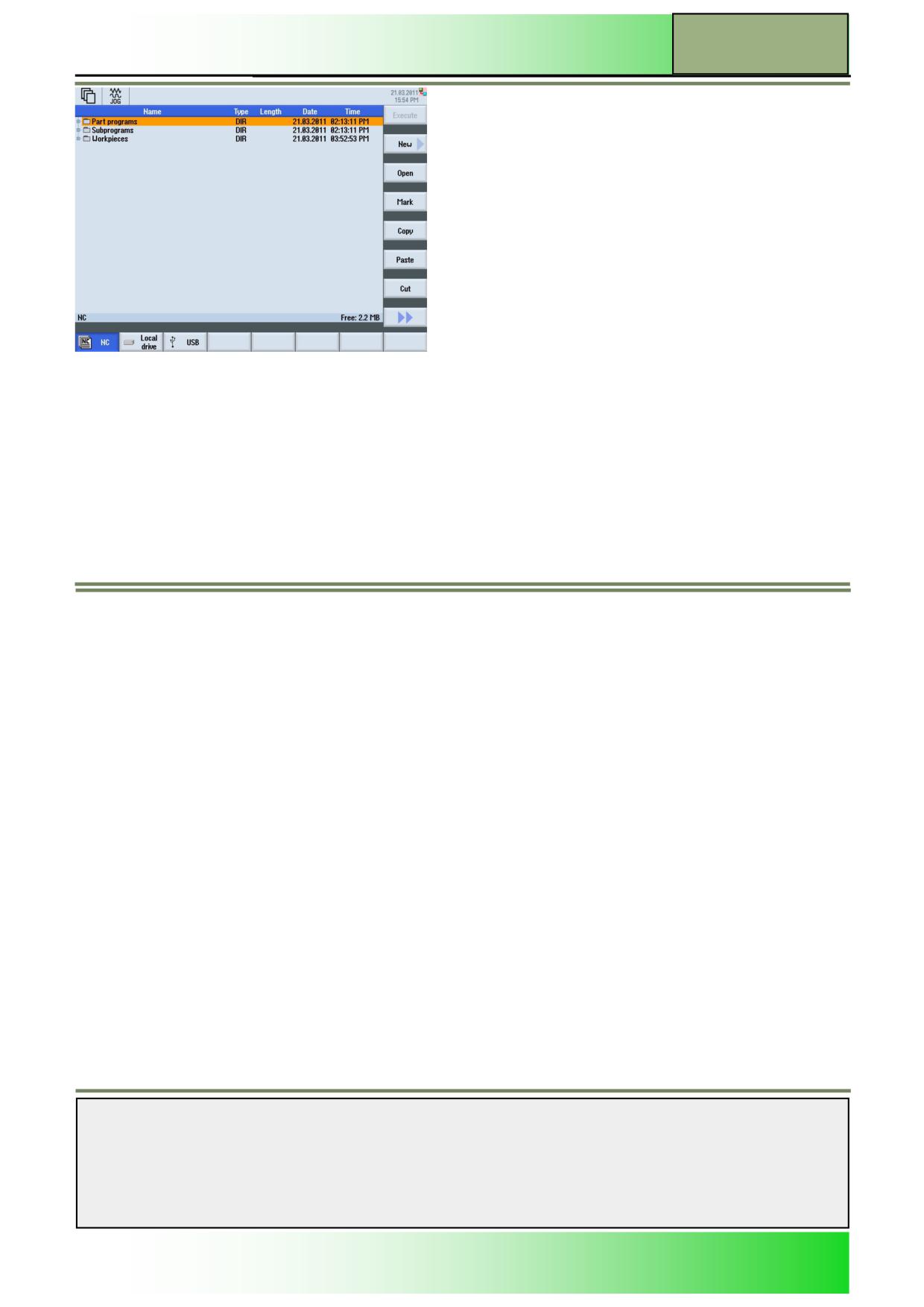
By pressing the HSK 1 “NC“ the program manager opens .
Notes
M525
Page 4
828D/840Dsl SINUMERIK Operate
Operating area “Program manager“
M525
The complete NC-memory is displayed along with all workpieces, the main programs and subroutines.
The directories and programs are listed with the following information:
Name
The name can contain up to 28 characters (24 characters for the name + dot + 3-character extension, e.g. MPF). Per-
missible characters include all upper-case letters (without accents), numbers, and underscores.
Type
*.WPD
Directory
(Workpiece Directory)
Directory/
*.MPF
Program
(Main program File)
Programs
*.SPF
Subprogram
(Subprogram File)
Size
The size of files of the selected directory is displayed in byte.
Date/Time
Date and time of file creation or last change
Notes
828D/840Dsl SINUMERIK Operate
Page 5
M525
M525
Operating area “Program manager“
Vertical softkey bar 1
Display area
Description
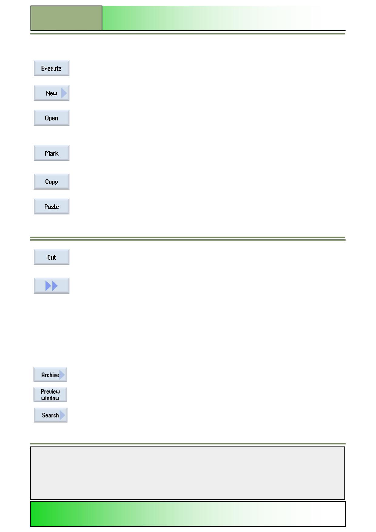
By pressing the VSK 1.1 “Execute“ you can select a program and change over to the operat-
ing area “Machine” in order to start machining the selected program.
By pressing the VSK 1.2 “New“ you can create a new directory. In the selected directory you
can create a new ShopMill- or a programGUIDE-program .
By pressing the VSK 1.3 “Open“ the selected program (marked with an orange cursor) will be
opened.
Alternatively you can also press the yellow “INPUT”-key on the keyboard or the blue “cursor
to the right”-key to open a program.
By pressing the VSK 1.4 “Mark“ several programs or directories can be marked for copying or
cutting.
By pressing the VSK 1.5 “Copy” one or several programs or directories can be copied.
By pressing the VSK 1.6 “Paste” the copied program(s) or directorie(s) are inserted into the
selected place in the directory tree of the NC, of a local drive or an USB drive.
By pressing the VSK 1.7 “Cut“ one to several programs or directories can be cut out and in-
serted somewhere else on a location in the directory tree of the NC, a local drive or on an
external USB drive.
By pressing the VSK 8 “Extend” the extended vertical softkey bar 2 with new functions will be
displayed.
Note:
Files can not be copied under the same name into the same directory.
The files are to be renamed.
Vertical softkey bar 2
Display area
Description (continuation)
By pressing the VSK 2.1 “Archive” a new vertical softkey bar is opened.
By pressing the VSK 2.2 “Preview window“ a sub window opens below the file browser win-
dow, with a preview of the program code of the selected program.
By pressing the VSK 2.3 “Search“ you can search for “File name”, using the Vertical softkeys.
Notes
M525
Page 6
828D/840Dsl SINUMERIK Operate
Operating area “Program manager“
M525
Vertical softkey bar 2
Display area
Description (continuation)
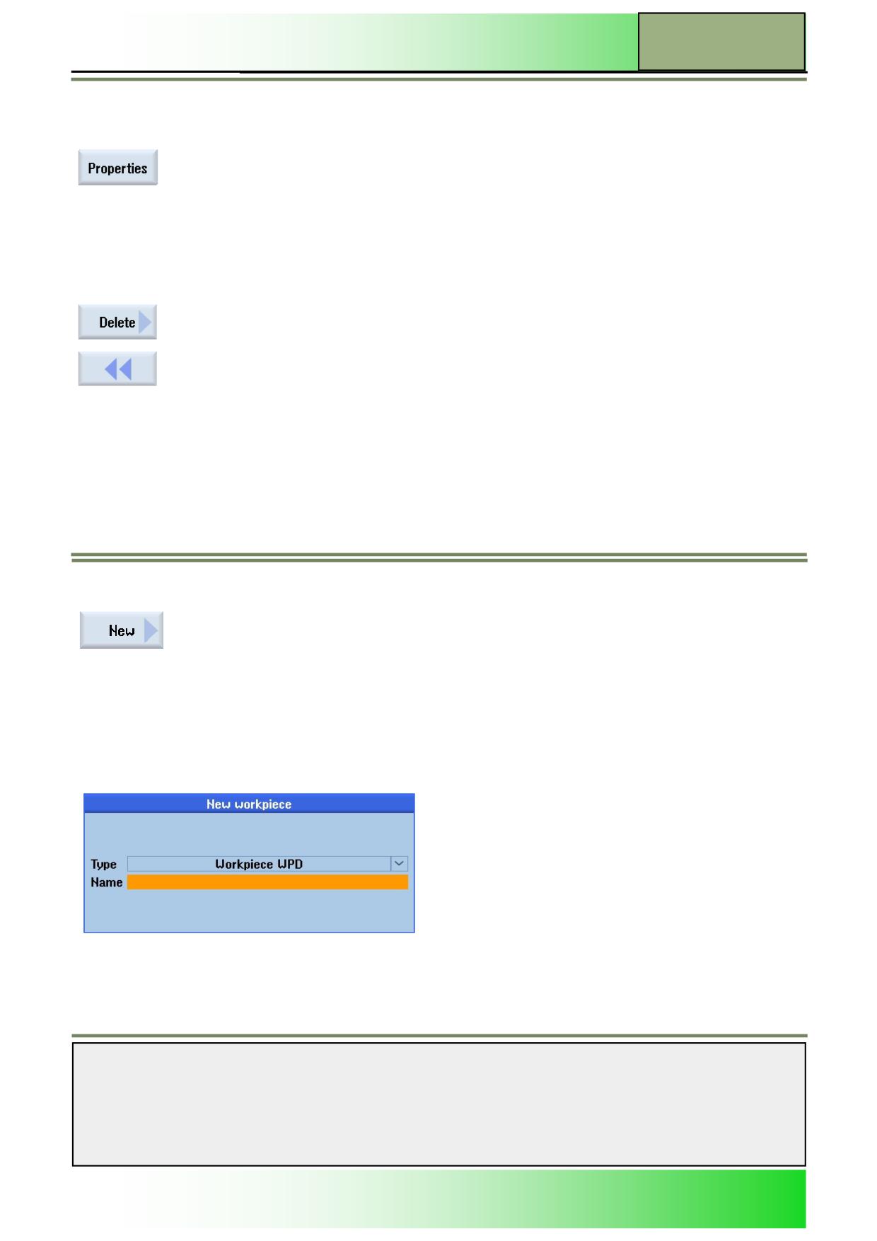
By pressing the VSK 2.6 “Properties“ the “Properties of ...” input mask opens where you can:
View program path and modify the program name.
View the time and date of creation.
View the time and date of last changing of the program or folder.
User rights for execution, writing, listing and reading of files and folders.
By pressing the VSK 2.7 “Delete“ the program or folder marked with the cursor will be deleted.
By pressing the VSK 2.8 “Back“ on the operator panel (OP) you switch back to the vertical soft-
key bar 1.
Starting a new NC-program
Press the VSK 1.2 “New“ to start a new G-code program or workpiece. Depending on the
cursor position the following input masks open.
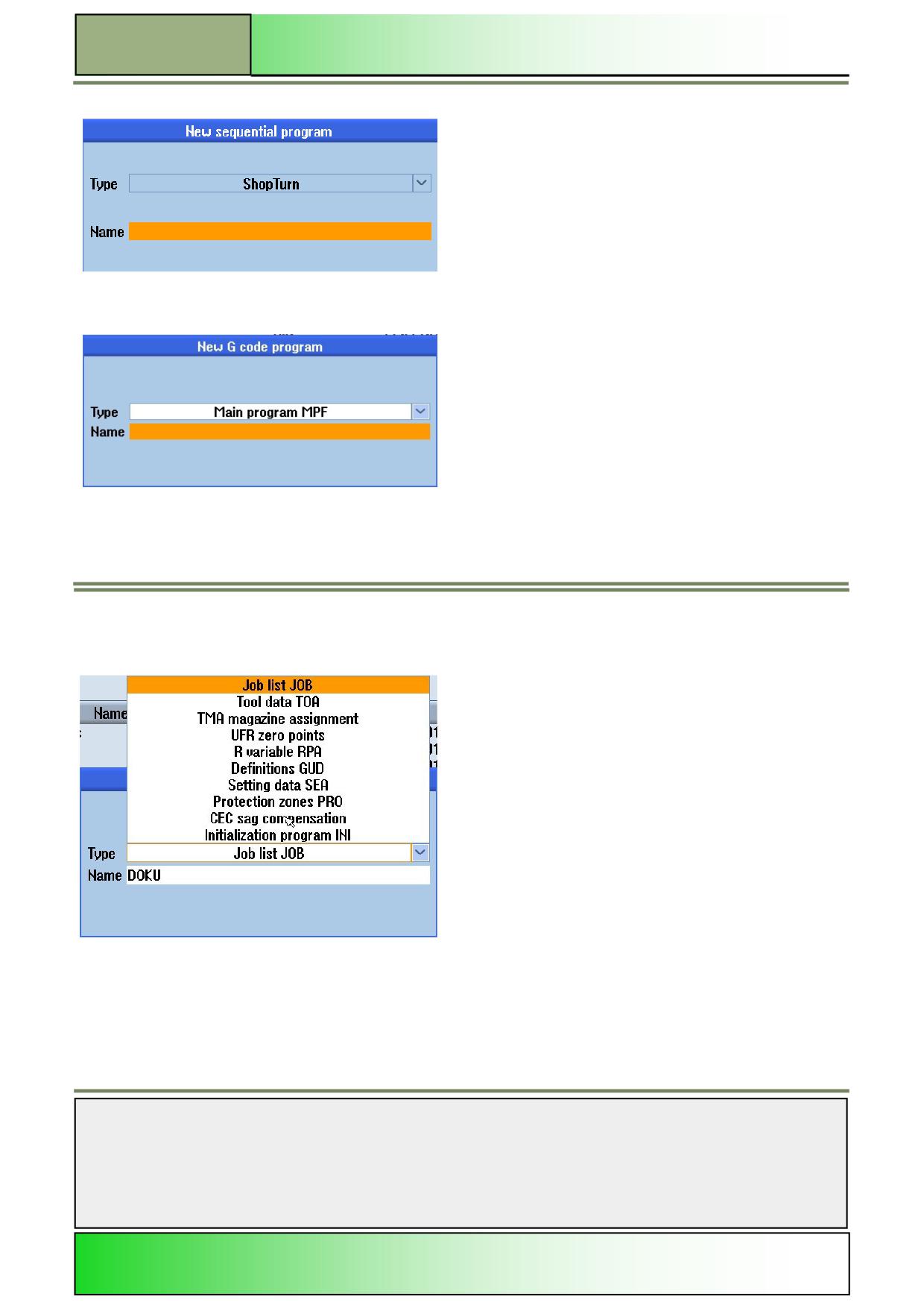
If the cursor is placed on the folder for part programs or subprograms, then a new G-code program of the type “*.MPF” (for
part programs) or “*.SPF” (for subprograms) is created by pressing the VSK 1.2 “New”.
In the name field of the input mask, a name for the program with a maximum of 28 characters (name + point + extension)
has to be entered.
Cursor is positioned on the directory (DIR):
With the VSK 2.1 “Directory” you can create a new Workpiece
directory (WPD).
Cursor is positioned on or in the workpiece directory (WPD):
Press the VSK 2.3 “ShopTurn” to create a new sequential program.
Notes
828D/840Dsl SINUMERIK Operate
Page 7
M525
M525
Operating area “Program manager“
Starting a new NC-program
Press the VSK 2.4 “programGUIDE G-code” to create a new G code program. In this case you select between a
main program (MPF) or a subprogram (SPF).
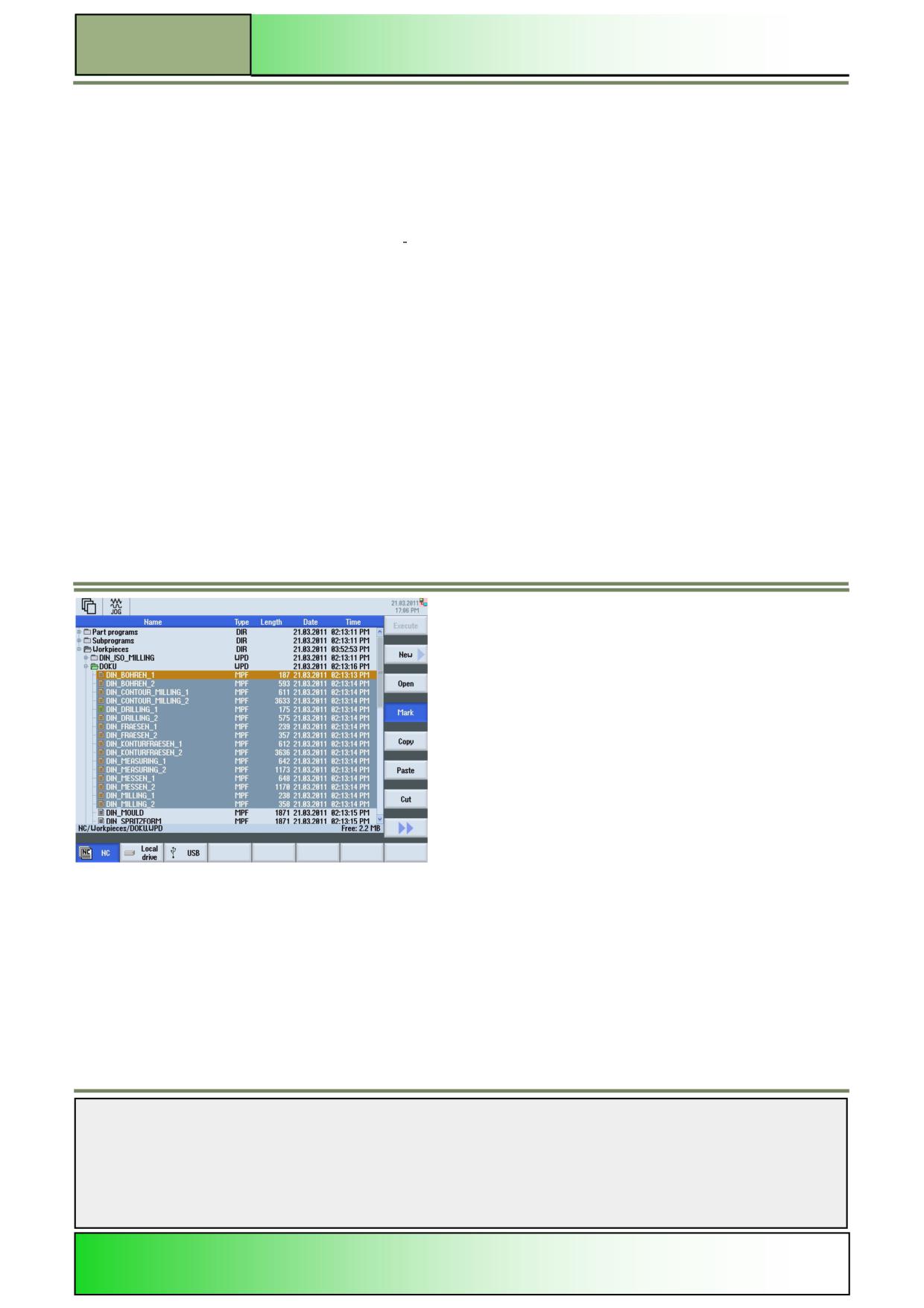
You can create a program of any type in every directory or subdirectory by pressing the VSK 5 “Any”. However in
the area “local drive” and “USB” this does not apply. Only in the area “NC” you can create a program of different
types (see the type list below).
After pressing the VSK 1.2 “New” the following functions in the vertical softkey bar are available.
Notes
M525
Page 8
828D/840Dsl SINUMERIK Operate
Operating area “Program manager“
M525
Vertical softkey bar
Display area
Description
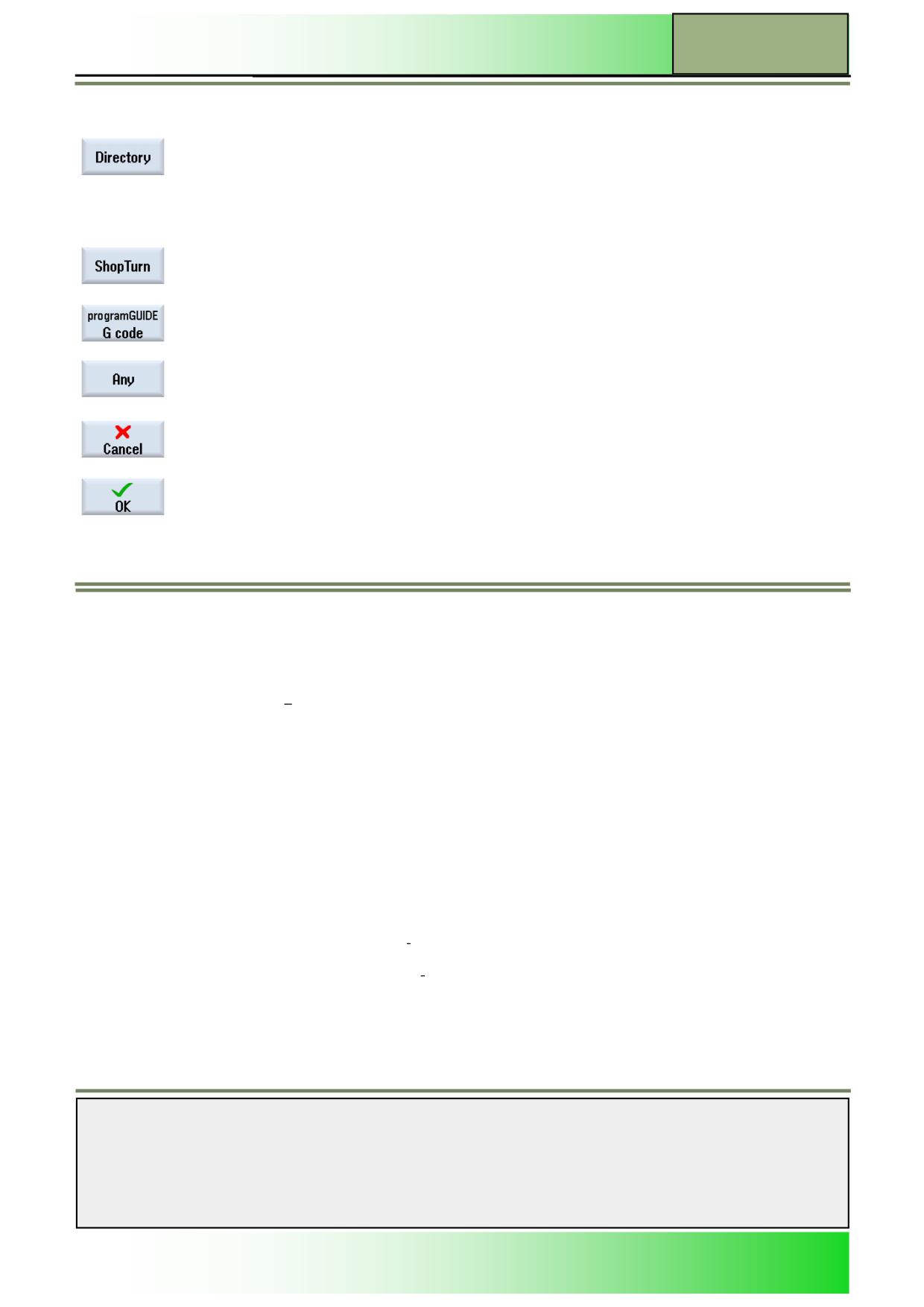
By pressing the VSK 2 “Directory“ you can create a new workpiece of the type *.WPD
(Workpiece directory).
The current cursor position determines the folder where the workpiece is created.
The “New workpiece” window opens.
Note: The softkey is only available if the HSK 1 “NC“ was selected before.
By pressing the VSK 2.3 “ShopTurn” a new sequential program will be created.
By pressing the VSK 2.4 “programGUIDE G code”, a new main program or subprogram will be
created, depending on the program type selected in the input mask.
By pressing the VSK 2.6 “Any“ an arbitrary program depending on the file type can be created
(see the picture above).
By pressing the VSK 2.7 “Cancel“ the actual selection will be discarded and the window closed.
By pressing the VSK 2.8 “OK“ or pressing the “INPUT”-key on the keyboard the entered values
or selection made will be accepted and the window closed.
Parameters for “New workpiece“
Parameter
Meaning
Type:
Program type:
WPD
Workpiece directory
Name
Program name:
The program name can only consist of a maximum number of 28 characters (Name + dot + 3-
character extension, e.g. *.WPD).
Permissible characters include all upper-case letters (without accents), numbers, and under-
scores (_).
Parameters for „New G code program“
Parameter
Meaning
Type:
Program type:
MPF
Program (Main program file)
SPF
Subprogram (Subprogram file)
Name
Program name
(see section above)
Notes
828D/840Dsl SINUMERIK Operate
Page 9
M525
M525
Operating area “Program manager“
Parameters for “Any new program“
Parameter
Meaning
Template
If templates are available, they are shown and selectable.
Type:
Program type:
MPF
Program (Main program file)
Name
Program name (see section above)
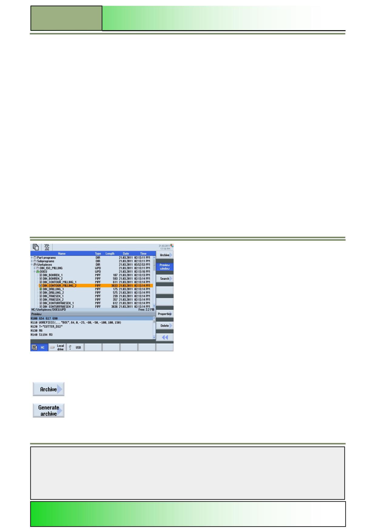
Marking directories / NC-programs
First open the desired directory in the program manager, like described in sections 2.1 and 3.1.
1.
Place the cursor with the blue “cursor down”-key on the first program or folder that you want to
mark.
2.
Press the VSK 4 “Mark“.
The program or directory selected with the orange cursor is marked.
3.
Mark more NC-programs or directories by pressing the blue “cursor down”-key.
All selected files or directories are marked grey.
Thereafter, the marked NC-programs can stored to the clipboard of the PCU by pressing the VSK 5 “Copy” or the VSK 7
“Cut” .
The programs stored to the clipboard can then be:
Copied in a different directory or to a different storage device
Deleted from a directory (cut) and pasted into a different directory or storage device.
Tip 1:
To shortcut the marking process place the cursor on the first program or directory you want to copy.
Now press the “SHIFT”-key on the keyboard, hold it pressed and move the cursor with the blue “cursor down” key to the
last program or directory you want to copy. Release the “SHIFT”-key.
The files are now marked.
Notes
M525
Page 10
828D/840Dsl SINUMERIK Operate

Operating area “Program manager“
M525
Tip 2:
If you only want to mark a single program or directory place the cursor on the file and press the blue “SELECT”-key on the
keyboard.
The single file is now selected.
Go on with copying, cutting or deleting, like described next.
Copying and pasting directories / NC- programs
First open the desired directory in the program manager, like described in section 2.1 and 3.1 in this module.
1.
Move the cursor with the blue cursor keys to the directory or file which you want to copy. If you want to copy
more then one program or directory, mark them first with the VSK 4 “Mark”.
2.
Press the VSK 5 “Copy“.
3.
If the program is to be copied into another directory on the NC, move the cursor with the “cursor to the
left”-key to the next higher level of the directory tree.
4.
Select the new directory where you want to copy the data with the “cursor up” and “cursor down”-key and
open the directory by pressing the “cursor to the right” or the yellow “INPUT”-key on the keyboard.
5.
Alternatively you can select another storage medium e.g. local drive or USB drive on the horizontal softkey
bar.
6.
By pressing the VSK 6 “Paste“ the program or directory can be inserted into the selected location.
Accept with pressing the VSK 8 “OK” or abort with pressing the VSK 7 “Cancel”.
The original file remains.
Tip 3:
To shortcut the copying process place the cursor on the program or directory you want to copy and press the CTRL + C
keys on the keyboard at the same time. In order to paste the file to another location move the cursor to that location and
press CTRL + V at the same time.
Cutting out directories / NC-programs
First open the desired directory in the program manager, like described in section 2.1 and 3.1 in this module.
1.
Move the cursor with the blue cursor keys to the directory or file which you want to cut out. If you want to cut
out more then one program or directory, mark them first with the VSK 4 “Mark”.
2.
Press the VSK 7 “Cut“.
In the message line the message “1 element has been cut. It can now be pasted” will be displayed.
3.
If the program or directory is to be moved to another directory on the NC, move the cursor with the “cursor
to the left”-key to the next higher level of the directory tree.
4.
Select the new directory with the “cursor up” and “cursor down”-key where you want to insert the data and
open the directory by pressing the “cursor to the right” or the yellow “INPUT”-key on the keyboard.
5.
Alternatively you can select another storage medium (e.g. USB stick) on the horizontal softkey bar.
Tip 4:
To shortcut the cutting out of a program or directory place the cursor on the selected file and press the CTRL + X keys at
the same time.
6.
Press the VSK 6 “Paste“ to insert the clipped data to the directory or storage location of your choice. Accept
your selection by pressing the VSK 8 “OK” or abort with pressing the VSK 7 “Cancel”. The source file or
directory will be deleted.
Notes
828D/840Dsl SINUMERIK Operate
Page 11
M525
M525
Operating area “Program manager“
Deleting directories / NC-programs
1.
Move the cursor with the blue cursor keys to the directory or file which you want to copy. If you want to copy
more then one program or directory, mark them first with the VSK 4 “Mark”.
Press the VSK 2.7 “Delete“ in the extended vertical softkey bar 2. Accept the deletion process with pressing
2.
the VSK 8 “OK” or abort with pressing the VSK 7 “Cancel”.
The selected program or directory will be deleted.
Opening a preview window
1.
Press the VSK 2.2 “Preview window” in the extended VSK-bar. The preview sub window opens directly
below the program manager window.
2.
Use the blue cursor keys to navigate to the program you want to preview. The program code of the selected
program is now displayed in the preview window.
3.
To deselect the function press the VSK 2.2 “Preview window” again.
The preview window disappears.
Note: You cannot edit program code in the “preview window”.
Tip 5: Press the “NEXT WINDOW“-key on the keyboard to activate the preview window. Now you can navigate freely
through the program code by using the blue cursor keys.
Tip 6: The preview window stays active, even if you switch back to the vertical softkey bar 1, in order to copy or cut a pro-
gram or directory.
Generating archive files of programs and directories
Vertical softkey bar
Pressing the VSK 2.1 “Archive” in the extended VSK-bar, will open the next vertical softkey
bar.
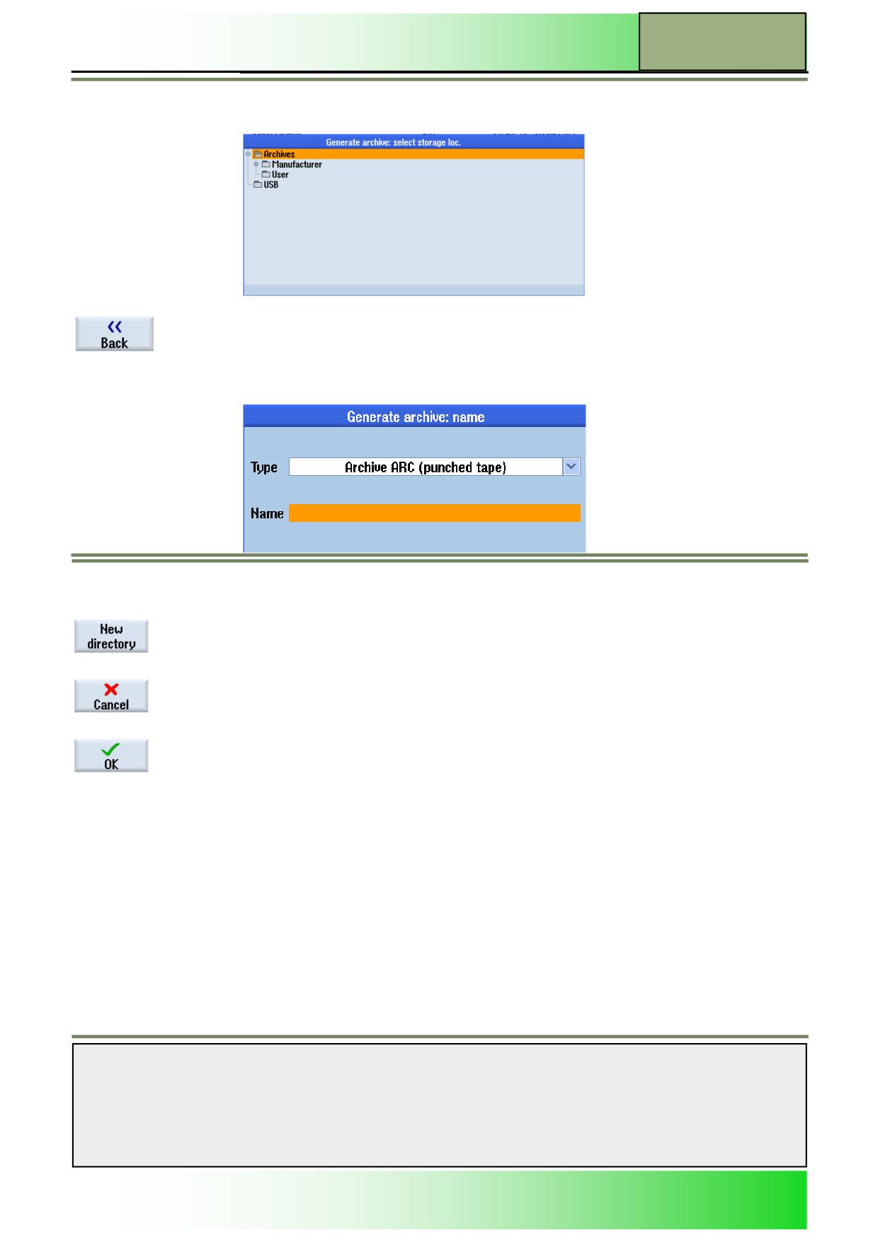
After pressing the VSK 3.1 “Generate archive” the following input mask appears to select the
storage location.
Notes
M525
Page 12
828D/840Dsl SINUMERIK Operate
Operating area “Program manager“
M525
Generating archive files of programs and directories
Vertical softkey bar
With the VSK 3.7 “Back” you can go back to the previous vertical softkey bar.
Afterwards the storage location is selected the next mask appears to enter the name of the
archive file.
Generating archive files of programs and directories
Vertical softkey bar
Pressing the VSK 4.2 “New directory” will open an input mask “New directory”, where you can
define a new directory at the selected cursor position.
Pressing the VSK 4.7 “Cancel” will abort the generating of archive files and the first vertical
softkey bar is selected.
Pressing the VSK 4.0 “OK” will start generating the archive file.
Notes
828D/840Dsl SINUMERIK Operate
Page 13
M525
M525
Operating area “Program manager“
Properties of programs and directories
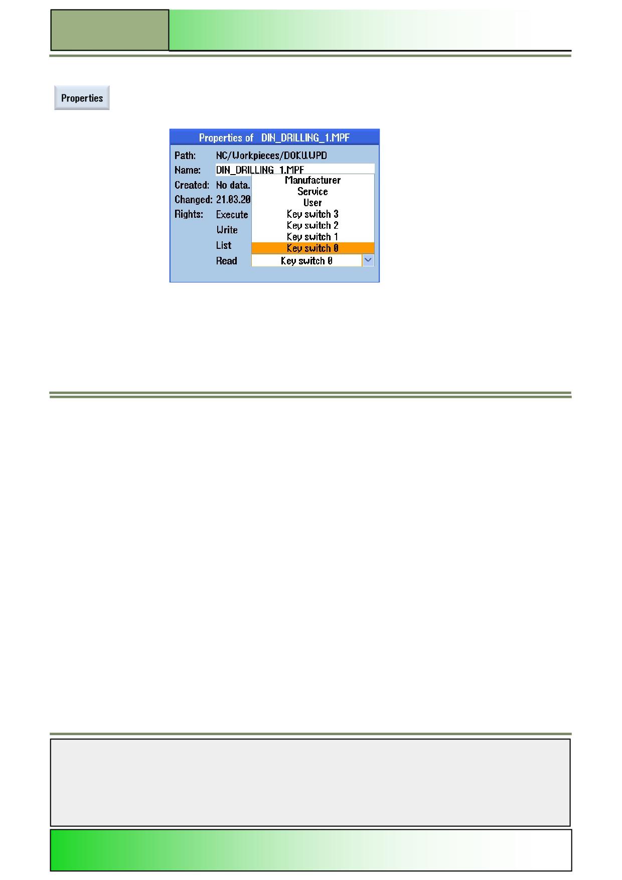
By pressing the VSK 2.6 “Properties” in the extended vertical softkey bar depending on the
cursor position and the selected program (here TEST.MPF) the “properties of
”-window with
security options for the selected program or directory opens.
Note: You can change the program name and the rights.
Parameters
Meaning
Path and name:
Program path and Program name;
The program with the name “TEST1.MPF” is located in the folder NC/Workpieces/DOKU.
Properties of programs and directories
Created:
Date and time of creation:
On the right side of the field “Created”: Date and time of creation are displayed here.
Changed:
Date and time change:
On the right side of the field “Changed”: Date and time since the last edit of the program are
displayed.
Rights:
User rights for executing, writing, listing and reading of a program or directory.
7 protection levels are possible (level 1 highest protection level, level 7 the lowest).
Manufacturer
Protected by password
Service
Protected by password
Protection level 1
User
Protected by password
Protection level 2
Programmer
Key switch 3
Protection level 3
Qualified worker
Key switch 2
Protection level 4
Skilled worker
Key switch 1
Protection level 5
Semi skilled worker Key switch 0
Protection level 6
Protection level 7
Notes
M525
Page 14
828D/840Dsl SINUMERIK Operate
Operating area “Program manager“
M525
Storage medium “Local drive”
Selecting the function “Local drive“
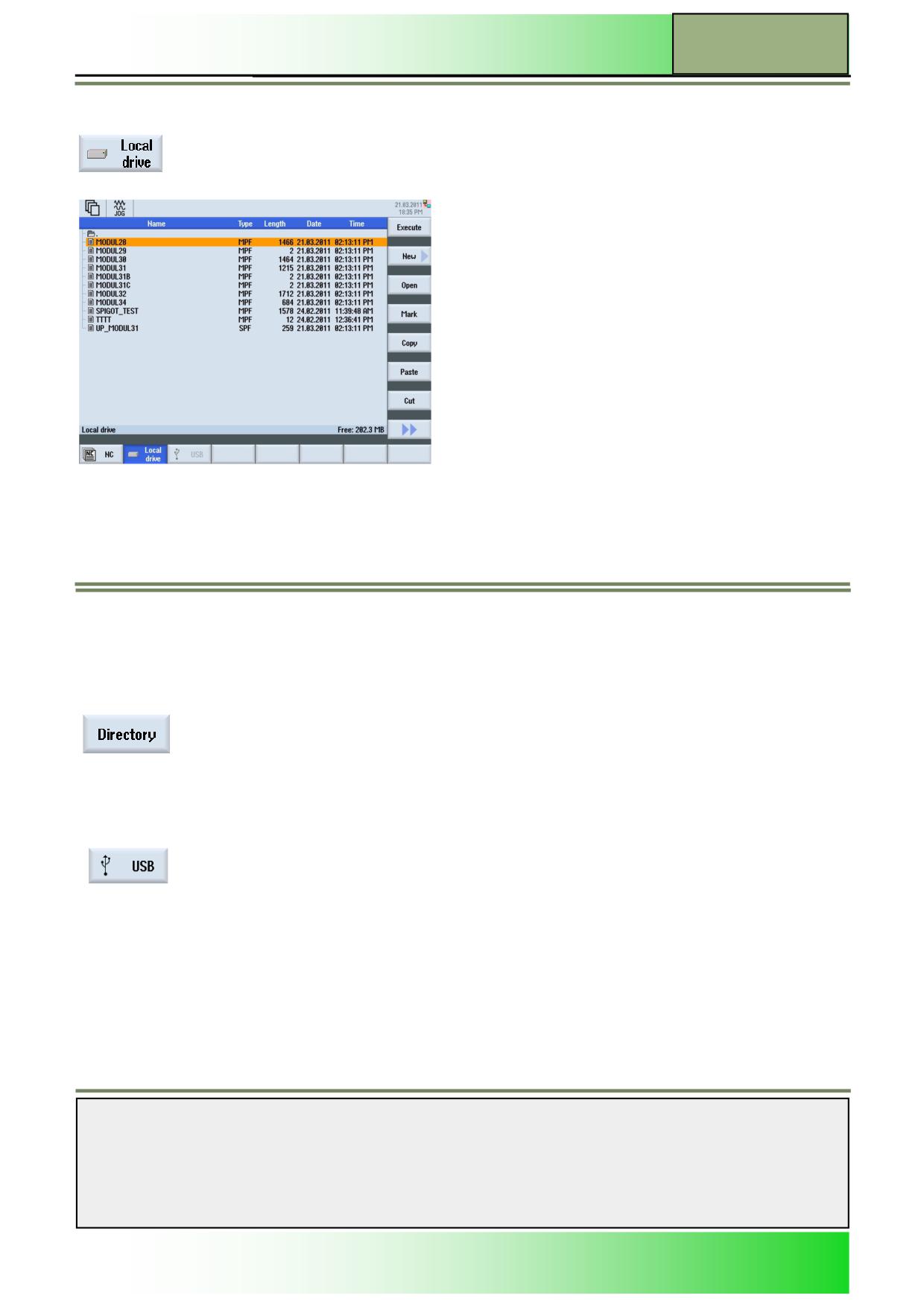
By pressing the HSK 2 “Local drive“ the program manager shows the directory structure of the
local drive.
A complete listing of all folders and files of the local drive is shown in the program manager window. For a description of the
information of name, type, length and date/time displayed in this window, see section 3.
Vertical softkey bar
The full functionality available under the NC program manager window is available by pressing the HSK 2 “local drive” or
HSK 3 “USB” (see section 3 in this module).
Additional, here you can create a new directory by pressing the VSK 1 “Directory”.
By pressing the VSK 1 “Directory” the “New directory” input mask opens where you can create
a new directory on the local drive.
Enter a name for the new directory and accept with pressing the VSK 8 “OK”, or abort with the
VSK 7 “Cancel”.
Storage medium “USB” drive
Selecting the function “USB“
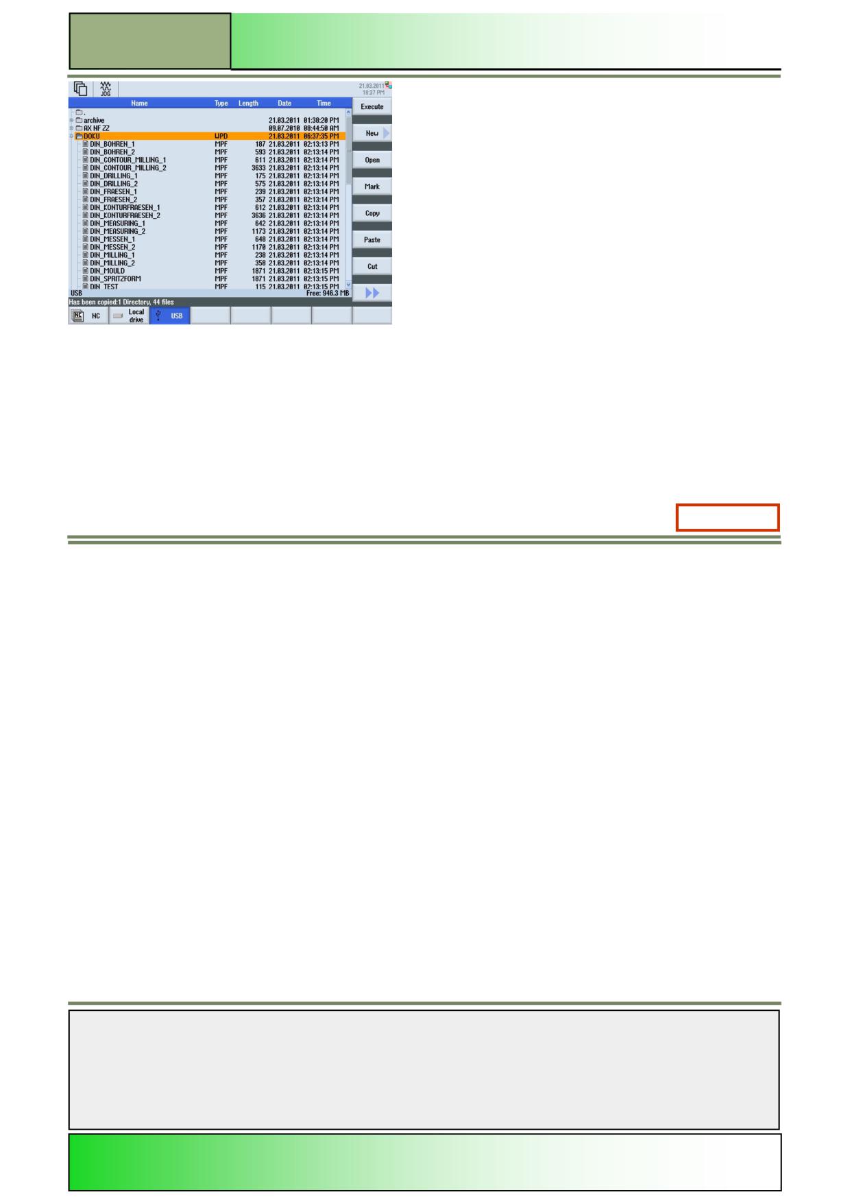
By pressing the HSK 3 “USB“ the following directory tree of the USB drive is displayed.
Notes
828D/840Dsl SINUMERIK Operate
Page 15
M525
M525
Operating area “Program manager“
A complete listing of all folders and files of the USB drive is shown in the program manager window. For a description of
the information displayed in this window.
Vertical softkey bar
The full functionality available under the NC program manager window is available by pressing the HSK 2 “local drive” or
HSK 3 “USB” (see section 3 in this module).
M525: END
Notes
M525
Page 16
828D/840Dsl SINUMERIK Operate
M601
Basics of programming with ShopTurn
Sinumerik
Operate
Module Description:
This module explains the general structure of a ShopTurn program which includes program header,
program block and program ending. In addition to this, the programming of chained programming
blocks (sequential programs), the functions of the “Editor”, as well as the functions “Various”, Simula-
tion” and “NC Execute” will be described.
Module Objective:
Working with this module you will learn the basics of creating ShopTurn sequential pro-
grams.
Content:
Basics
Creating ShopTurn programs
Editor
Various
Simulation
NC Execute
This document was produced for training purposes.
828D/840Dsl SINUMERIK Operate v4.7
Page 1
M601
Siemens assumes no responsibility for its contents.
M601
M601
Page 2
828D/840Dsl SINUMERIK Operate
Basics of programming with ShopTurn
M601
Basics of
programming with
ShopTurn:
START
Basics
Creating
ShopTurn
programs
Editor
Various
Simulation
NC Execute
Basics of
programming with
ShopTurn:
END
Notes
828D/840Dsl SINUMERIK Operate
Page 3
M601
M601
Basics of programming with ShopTurn
Basics
Programming with ShopTurn
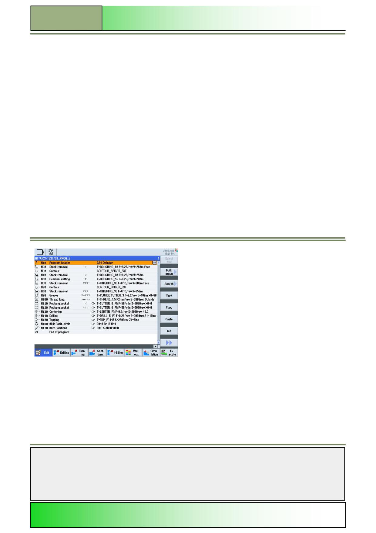
ShopTurn offers the option to create NC programs directly on the control in the manner of chained sequential block pro-
grams. It also offers the option to program G-code programs directly, with additional ShopTurn functionality.
Note:
The creation of G-code programs in ShopTurn is discussed in details in the module M605 “ Basics of programming with the
programGUIDE”.
The advantage of programming a ShopTurn program lies in the graphical guiding of the programming process in the editor.
The following functions are available for this task:
Technology oriented program step (technologies/cycles) selection using softkeys
Input masks and windows for parameters, with animated help graphics
Context sensitive online help for every input mask and window
Support for the contour input (geometric processor)
ShopTurn programs or program steps can be represented in different ways:
As a work plan, showing the program header, the programming steps with their chaining and the end of the program.
Notes
M601
Page 4
828D/840Dsl SINUMERIK Operate
Basics of programming with ShopTurn
M601
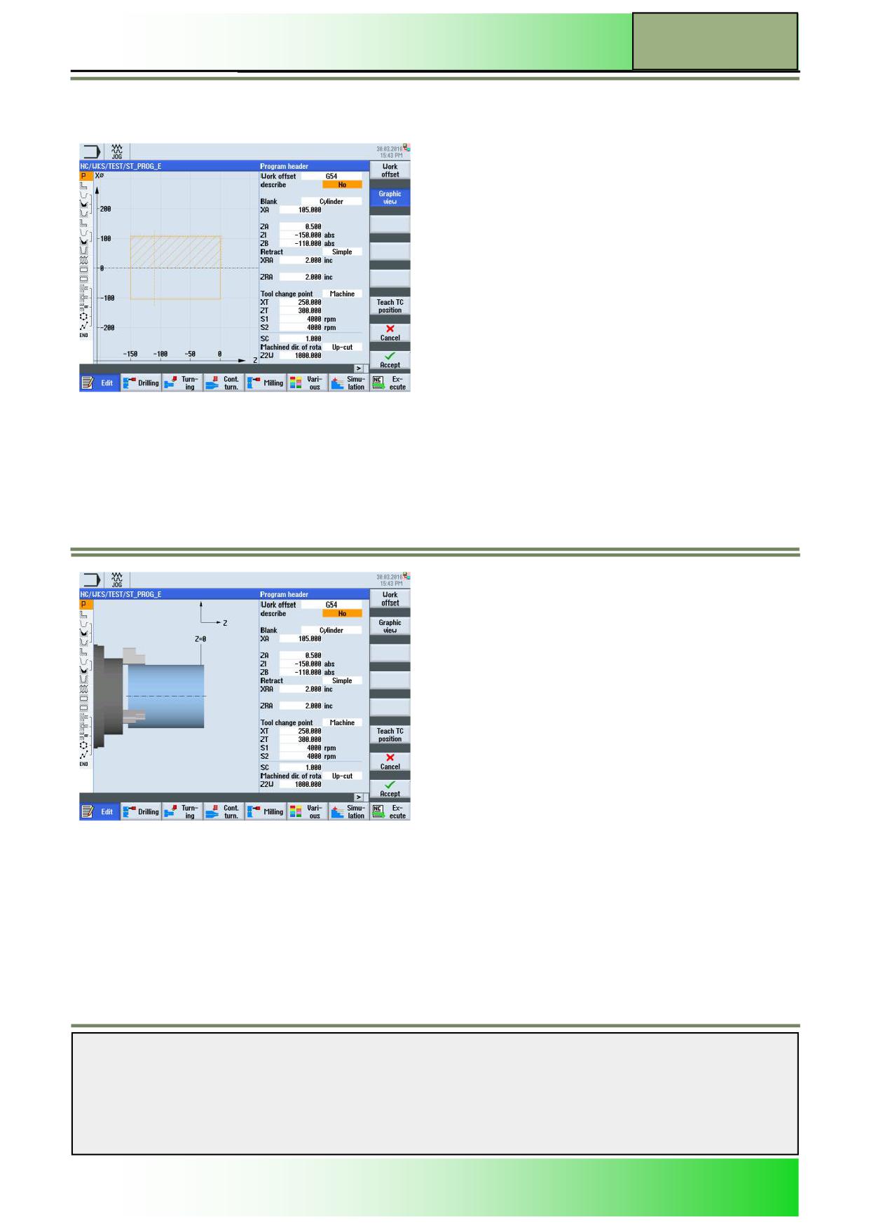
As a programming graphic in the graphic view (workpiece or machining step as an outline graphic in side view or top
view).
The marked program block in the work plan is highlighted in a different colour.
As a parameter mask with a help graphic in 3-D, or a simulation of the machining step in side, face view and 3D. If
available, the view changes continuously from the help picture to the animation.
Note:
The animated help graphics are displayed always in the correct position to the adjusted coordinate system. The parameters
are dynamically displayed and the selected parameter in the graphic is highlighted in a different colour.
Notes
828D/840Dsl SINUMERIK Operate
Page 5
M601
M601
Basics of programming with ShopTurn
The work plan
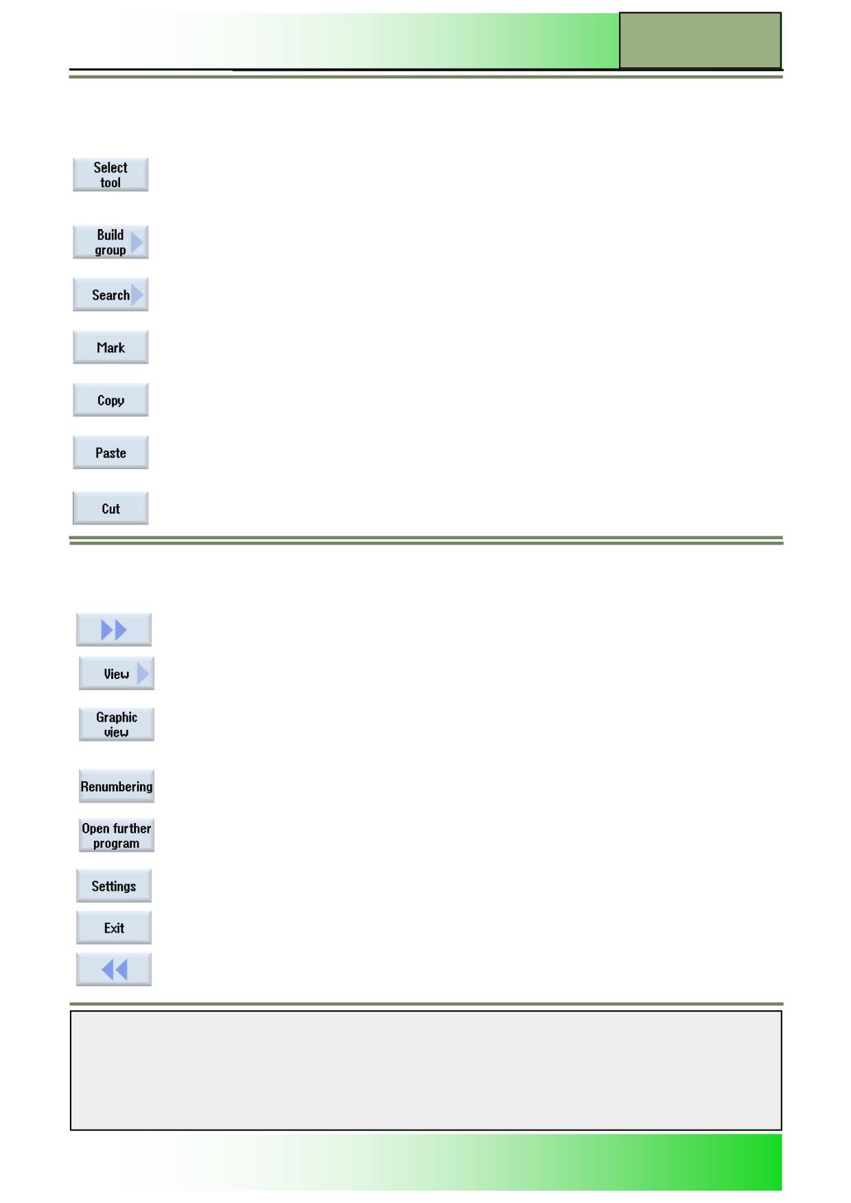
Main aspect of programming with ShopTurn is the “Work plan” in the editor window. The structure of the “Work plan” is as
below:
Program header (with the base settings for the program, like measurement units, work offset, blank dimensions, etc.)
Program blocks (the program steps with the technologies/cycles)
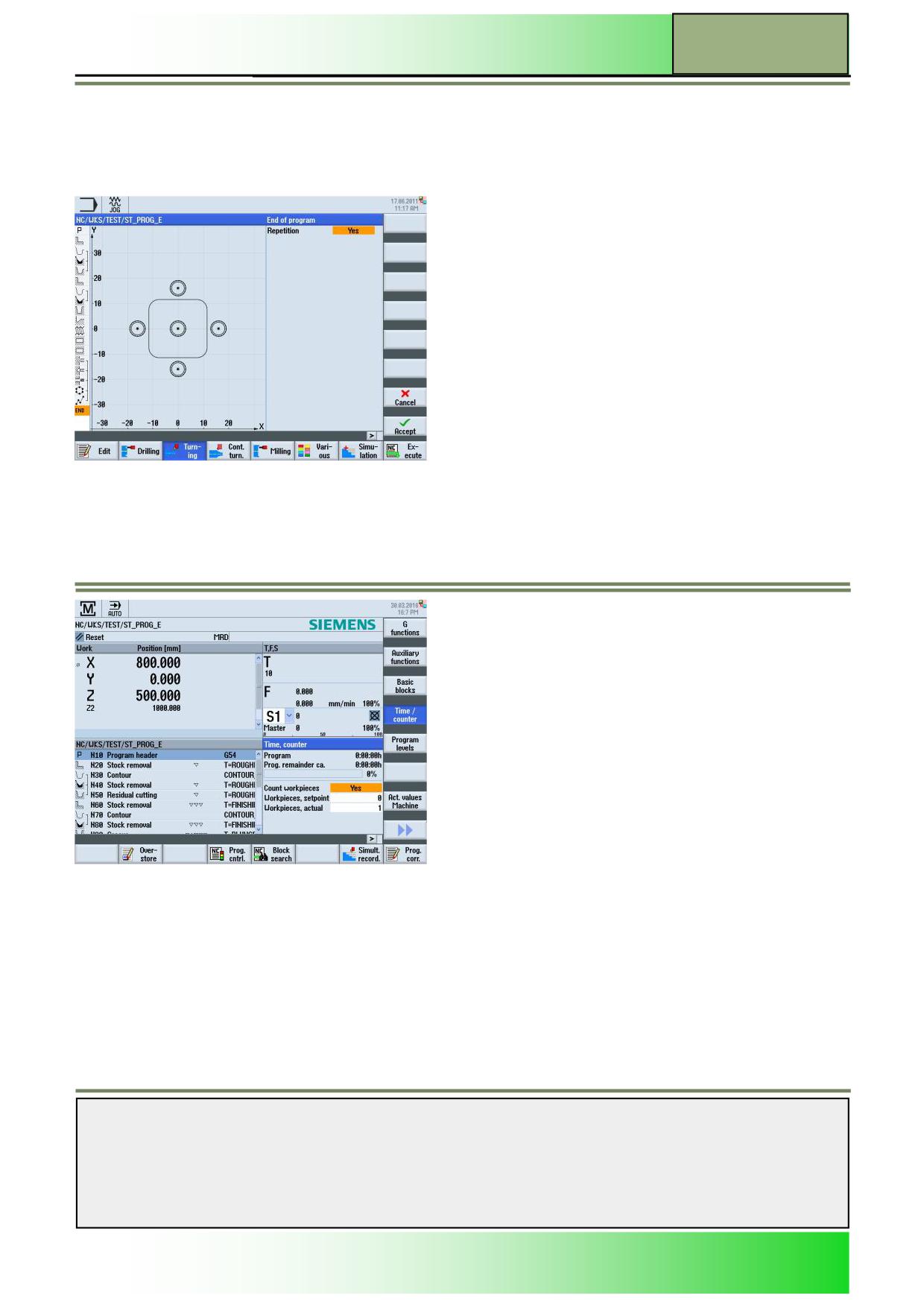
End of program (where you can finish the program and adjust the numbers of workpieces you want to machine, see
also picture below)
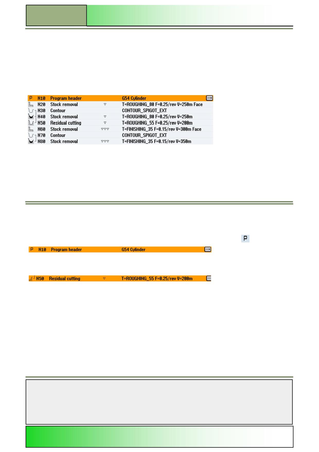
Program header
The program header (see picture above on the left and section 3.2)contains the dimensions of the blank for the simulation,
as well as the parameters that influence the whole program e.g.
Work offset
Spindle
Measurement units in mm or inch
Tool axes X, Y or Z
Retraction plane, tool change point, safety distance, speed limits etc.
In the work plan, the program header is at the beginning of the program and is labelled with the icon
, the text “Program
header” and the corresponding parameters.
Program blocks
Program blocks are programmed machining steps which are shown in the editor in single rows, marked with an icon and
text, representing the corresponding technology and the entered parameters (see picture below).
Chained sequential program blocks
For the Functions “Drill”, “Turning”, “Contour turning”, “Milling” and “Straight Circle” technology blocks are programmed
separately. These program blocks are automatically chained together by the control and connected by brackets in the work
plan.
Technology blocks, specify in which way the machining should take place (e.g. centring first, and then drilling). The posi-
tioning blocks determine the positions for the drilling, milling or turning operations (e.g. position the drill-holes in a full
circle on the front surface) and the contour blocks describe the contour you want to machine.
A program chain is closed when a technology element is completed with a position element. Otherwise an error mes-
sage lets you know if one of the parts is missing.
Notes
M601
Page 6
828D/840Dsl SINUMERIK Operate
Basics of programming with ShopTurn
M601
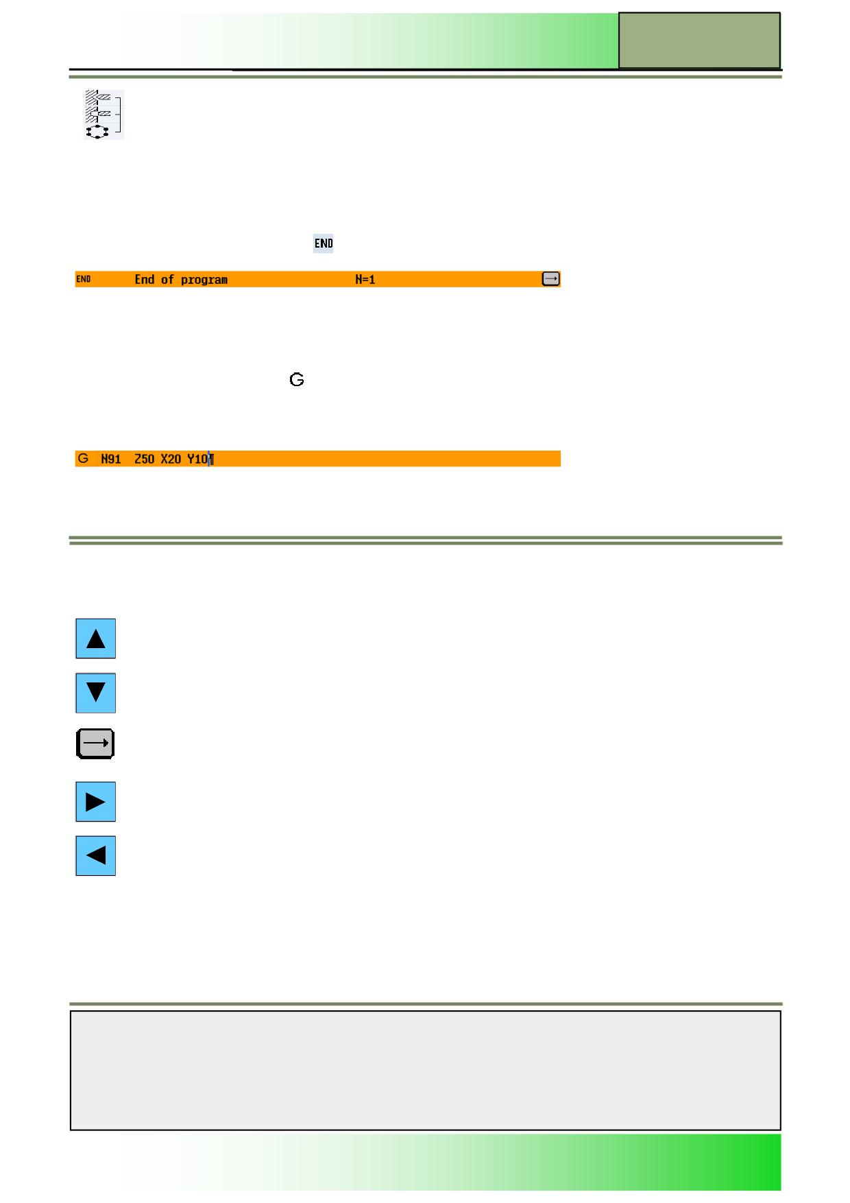
The Icons of the chained technology blocks and position blocks are marked by a square bracket to the
right of the machining symbol from the start to the end of the linkage.
Every Technology is represent-
ed by a unique symbol (icon). The chained icons are also being displayed on the right side of the screen
in the programming graphic and parameter mask window. (here centring, drilling linked with a position cir-
cle pattern).
End of program
End of the program signals to the machine that the machining of the
workpiece has ended. In addition, you can specify the number of
workpieces that you would like to machine.
This program block is marked by the icon
, as well as the lettering “End of Program” with a letter “N”, indicating the
number of workpieces you want to machine:
G code blocks
In the work plan you can also insert G code program blocks.
For this, you must press the yellow “INSERT”-key on the keyboard on the desired place in the program. A a new orange
command line, marked with the letter
and a blinking cursor where you can enter G code commands opens. Here you
can enter now a G code command. With the blue “cursor-down” or “cursor-up” you can exit the G code command line and
the inputs are taken over.
From a G code line you can not switch to a parameter mask window.
Navigation in the editor window
For a fast and comfortable navigation within a sequential program and the parameter masks you can use the blue cursor
keys.
With the blue “cursor-up” key on the keyboard you can navigate upwards in the program editor and the pa-
rameter masks.
With the blue “cursor-down”-key on the keyboard you can navigate downwards in the program editor and
the parameter masks.
The arrow symbol (extend-symbol), on the right side of the program block line in the editor window, indicates
that you can access the parameter mask by pressing the “cursor-to-the-right” key.
The “cursor-to-the-right” key opens the parameter mask of the corresponding program block.
The “cursor-to-the-left” key closes the parameter mask of the corresponding program block and brings you
back to the work plan window, displaying the ShopTurn program steps.
Notes
828D/840Dsl SINUMERIK Operate
Page 7
M601
M601
Basics of programming with ShopTurn
Creating ShopTurn programs
Creating a new ShopTurn program
A new ShopTurn program can be created from the operating modes “JOG”, “MDA” and “AUTO” as follows:
Press the “Program Manager“ key on the keyboard.
The window for creating new programs and managing existing programs opens directly.
See module M525 - „Operating area Program Manager“.
- OR -
Press the “MENU SELECT“ key on the operator panel (OP).
Press the yellow HSK 4 “Program Manager“.
The program manager window for creating new programs and managing existing programs
opens.
- THEN -
Select a storage drive, by pressing the horizontal softkey “NC”, “Local drive” or “USB”,
where you want to create the program.
Move the orange cursor with the blue cursor-keys to the directory of your choice.
For the navigation process refer to the modules M516 - “Operating elements“ or M525 -
“Operating area Program Manager“.
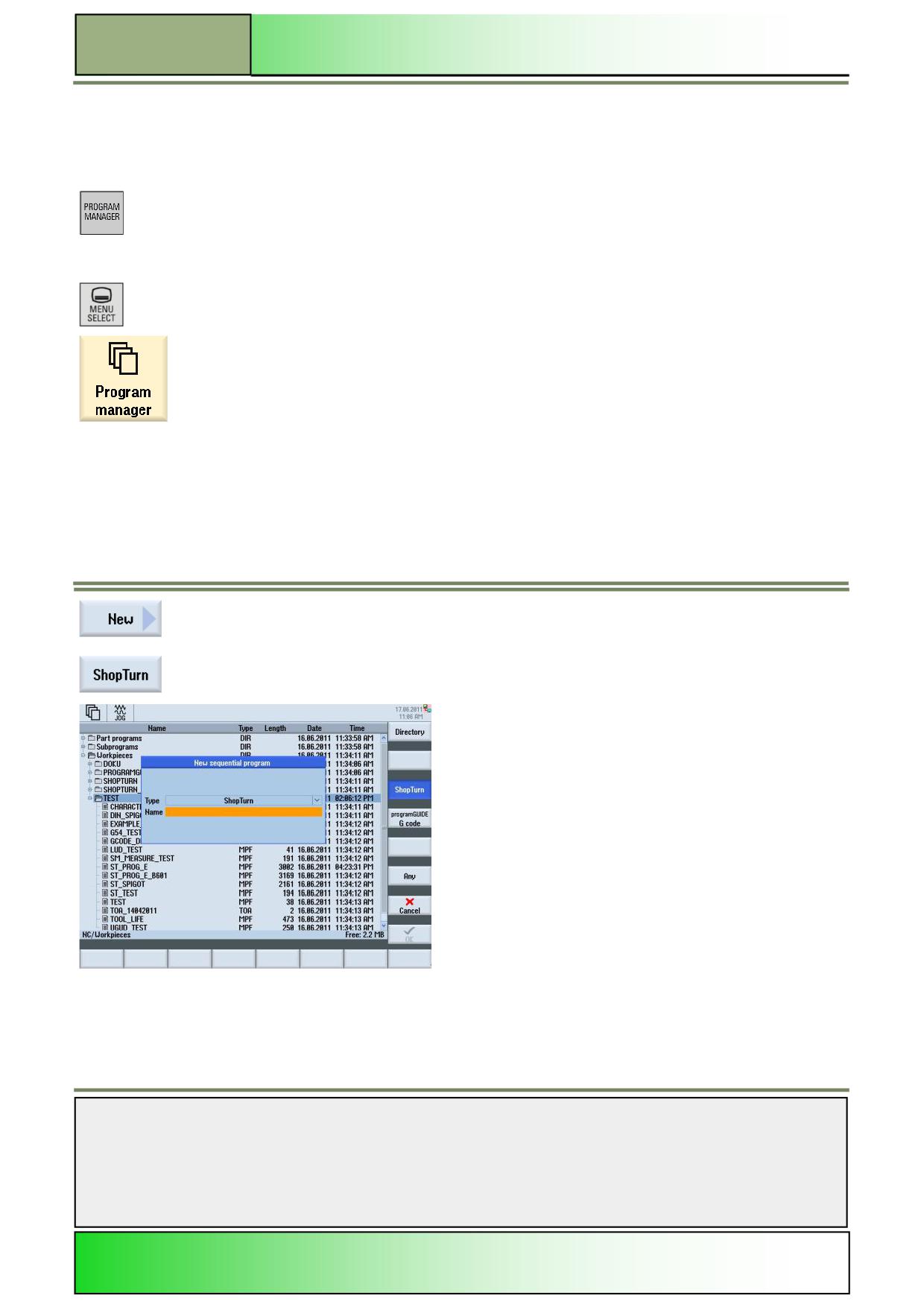
Press the VSK 2 “New”.
The vertical softkey bar with functions for creating new programs opens.
Press the VSK 3 “ShopTurn”, to open the input mask for creating a new sequential Shop-
Turn program like displayed below.
Notes
M601
Page 8
828D/840Dsl SINUMERIK Operate
Basics of programming with ShopTurn
M601
Setting the program header
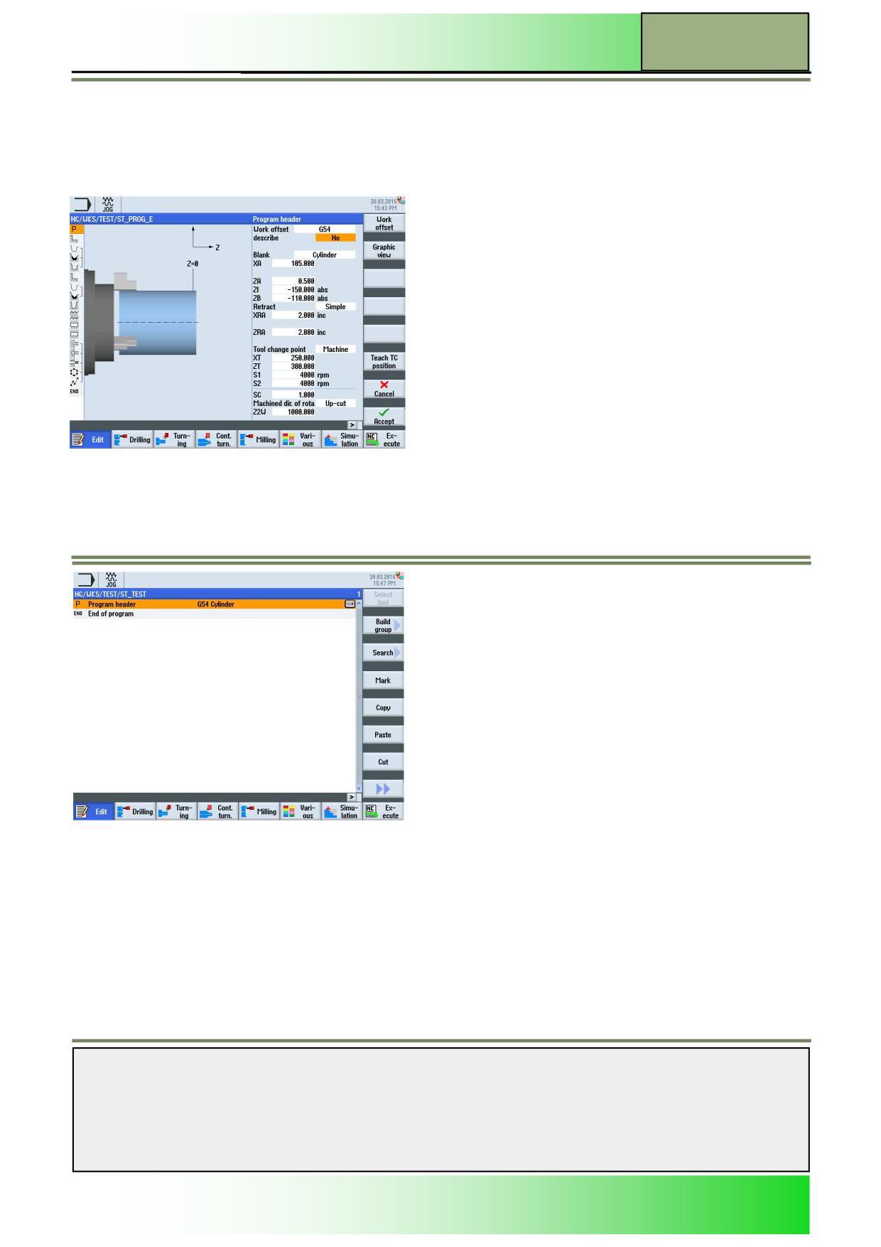
After entering a name for the program and pressing the VSK 8 “Accept” the program header window opens automatically
for input of program header parameters. Here you can enter parameters for the measuring units, the work offset, the spin-
dle, the blank, the retraction mode, the tool change point, the safety distance, the speed limits and the machining sense (as
shown e.g. below).
Enter the appropriate parameter values and confirm with pressing the VSK 8 “Accept” or abort with pressing the VSK 7
“Cancel”, to switch back to the work plan window.
The control switches to the work plan view in the program editor.
Program header and end of program are programmed automatically.
Notes
828D/840Dsl SINUMERIK Operate
Page 9
M601
M601
Basics of programming with ShopTurn
Creating program blocks
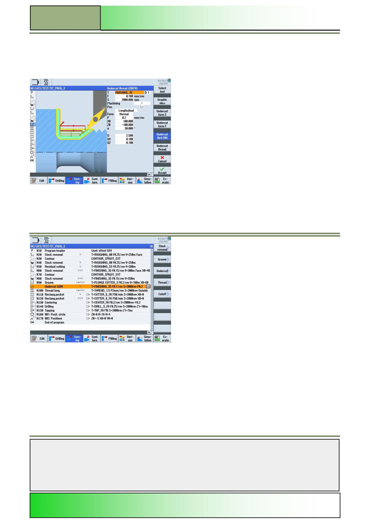
Place the cursor on the program header block, or any other program block after which you want to insert a new program
block. Select the technology you want to apply (“Drilling”, “Turning”, “Contour turning”, “Milling” or “Straight Circle”). For ex-
ample select “Turning” -> “Undercut” -> “Undercut thread DIN” to open the corresponding parameter window for this tech-
nology (see picture below).
Enter the appropriate parameter values and confirm with pressing the VSK 8 “Accept” or abort with pressing the VSK 7
“Cancel”. You switch back to the work plan view in the editor window.
The new program block is inserted automatically into the work plan.
The “cursor-to-the-right” key opens the parameter window at any time, to change the input parameters you have edited
before.
The additional program steps can be added as described above.
Notes
M601
Page 10
828D/840Dsl SINUMERIK Operate
Basics of programming with ShopTurn
M601
Programming the end of the program
The program block “End of program” is programmed automatically whenever you create a new ShopTurn program.
To modify the default settings for the program end, mark the line “End of program” with the orange selection cursor and
press the blue “cursor-to-the-right” key.
The parameter window for the program end opens, where you can modify the numbers of workpieces you want to machine.
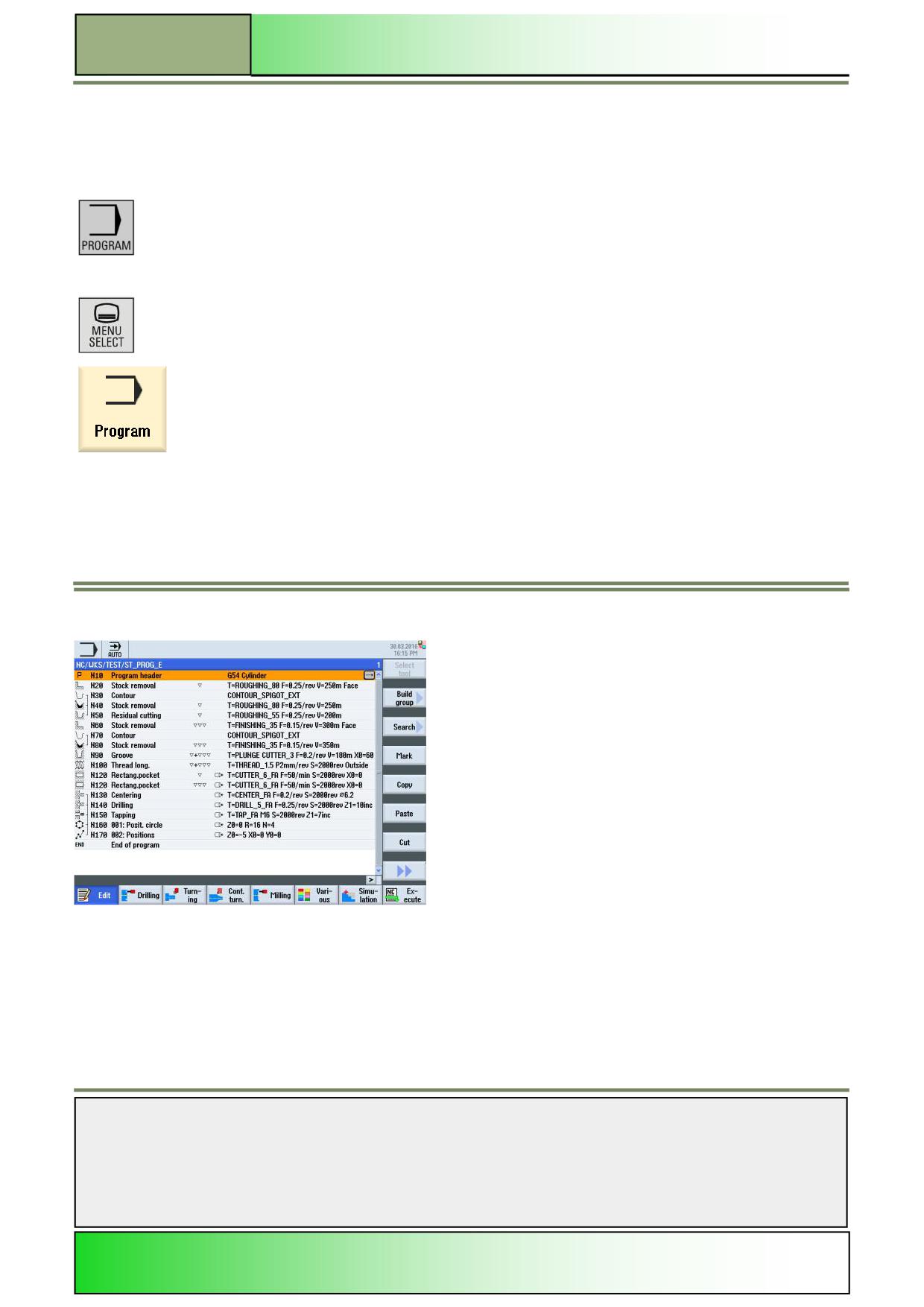
Enter the numbers of workpieces you want to machine from the machine page in “AUTO” mode as shown below.
Notes
828D/840Dsl SINUMERIK Operate
Page 11
M601
M601
Basics of programming with ShopTurn
With the editor you can create, supplement and change part programs.
Editor
Selecting the function “Edit“
The function “Editor” can be opened from the operating mode “JOG”, “MDA“ and “AUTO“.
By pressing the “PROGRAM“-key on the keyboard
the operating area “Program” opens, showing the last program you have worked on.
- OR -
Press the “MENU SELECT“-key on the operator panel (OP).
Press the yellow HSK 3 “Program“ to switch to the operating area “Program“.
The operating area “Program” opens, showing the last program you have worked on (see pic-
ture below).
If not selected, press the HSK 1 “Edit”.
If no program was loaded after starting the control,
the “program manager” window opens first, after pressing the HSK 3 “Program”.
Here you can select either a existing ShopTurn-program or create a new one.
The following softkeys with their corresponding functions are now available in the vertical softkey bar:
Notes
M601
Page 12
828D/840Dsl SINUMERIK Operate
Basics of programming with ShopTurn
M601
Vertical softkey bar 1 and 2
Display area
Description
In a ShopTurn program the tool call is inside the cycle mask. The function “Select tool” is available
for ShopTurn programs under the technologies “Drilling”, Turning, “Contour turning”, “Milling”,
“Straight Circle” or in a corresponding program block with tool utilization. This is the reason for VSK
1.1 “Select tool” being grayed out (inactive) as long their is no G code line inserted.
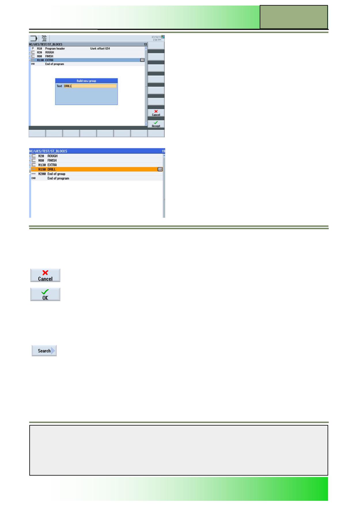
By pressing the VSK 1.2 “Build group” you can create programme blocks into groups, this can be
useful when creating large programs.
By pressing the VSK 1.3 “Search“ you can search for any text in the program blocks. A search win-
dow opens where you can enter a search string. You can continue searching afterwards.
By pressing the VSK 1.4 “Mark” you can mark one or several program blocks in order to copy or cut
(delete) them.
By pressing the VSK 1.5 “Copy” you can copy one or several program blocks to the internal memory
of the control, to paste them to a different location in the active program or to another program.
By pressing the VSK 1.6 “Paste“ copied or cut program blocks can be inserted behind the selected
program block (actual cursor position). You can paste the block to the active program as well as to
another ShopTurn program.
By pressing the VSK 1.7 “Cut” you can cut out one or several program blocks, to paste them later
somewhere in a program or to delete them. Cut out program blocks remain in the clip board and can
be inserted again with the VSK 1.6 “Paste”.
Vertical softkey bar 1 and 2 continued
Display area
Description
By pressing the VSK 1.8 “Extend“ the extended vertical softkey bar 2 will be displayed.
By pressing the VSK 2.1 “View” you can choose between “Close all blocks” and “Open all
blocks”.
By pressing the VSK 2.2 “Graphic view” you can see the simulated workpiece from a top view as an
outline drawing.
Note SK only visible in ShopTurn
By pressing the VSK 2.3 “Renumbering” you can assign new numbers for every program step in the
Work plan window.
By pressing the VSK 2.4 “Open further program” you can view two programs side by side.
By pressing the VSK 2.6 “Settings“ you can change the settings for the editor.
By pressing the VSK 2.7 “Exit” you close the editor with the active program.
By pressing the VSK 2.8 “Back“ you switch back to the vertical softkey bar 1.
Notes
828D/840Dsl SINUMERIK Operate
Page 13
M601
M601
Basics of programming with ShopTurn
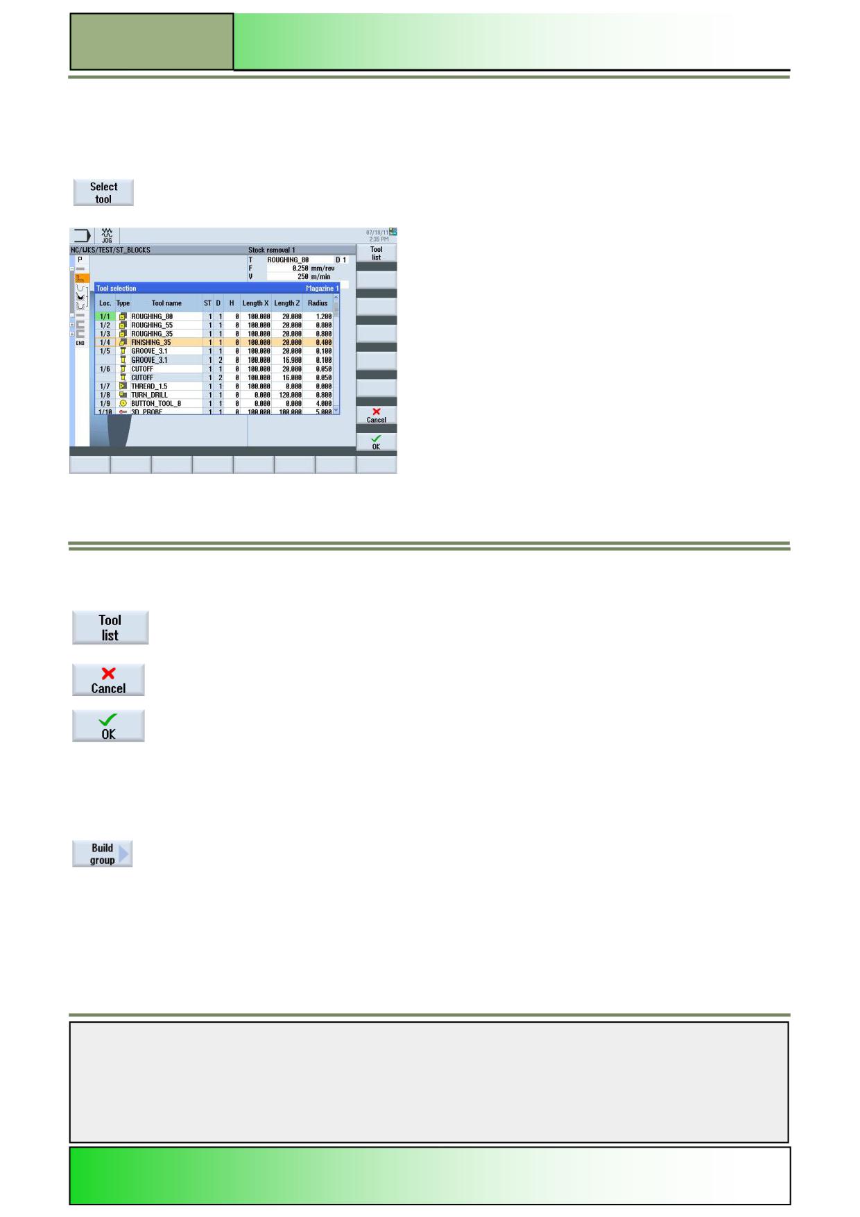
Select tool
With the function “Select tool” you can search and select a tool .
Selecting the function “Select tool”
By pressing the VSK1.3 “Select tool” the search window opens like displayed below, with the
following functions available in the vertical softkey bar.
Use the “cursor up & cursor down” keys on the key board the select the required tool for the machining block.
If the required tool is not available press the VSK1 “Tool list” so that a new tool can be created .
Vertical softkey bar
Display area
Description
By pressing the VSK 1 “Tool list” you are taken to the tool list.
See module - M523 “Operating area Parameter”.
With pressing the VSK 7 “Cancel” you can abort the search process.
By pressing the VSK 8 “OK“ you will load the selected tool into the machining block.
Build group
With the function “Build group” you can group similar machining blocks together .
Selecting the function “Build group”
By pressing the VSK1.2 “Build group” the build new block window opens like displayed below,
allowing you to give a name to a group
Notes
Once you have typed in a name press the “OK” softkey
M601
Page 14
828D/840Dsl SINUMERIK Operate
Basics of programming with ShopTurn
M601
Once you have typed in a name press the “OK” softkey
You can now create machining blocks inside the group.
Vertical softkey bar
Display area
Description
With pressing the VSK 7 “Cancel” you can abort the search process.
By pressing the VSK 8 “OK“ you will load a new group block into the program with the name
you have chosen.
Search
With the function “Search” you can search for any text in a sequential program and even replace the text with other text.
Selecting the function “Search”
By pressing the VSK1.3 “Search” the search window opens like displayed below, with the follow-
ing functions available in the vertical softkey bar.
Notes
828D/840Dsl SINUMERIK Operate
Page 15
M601
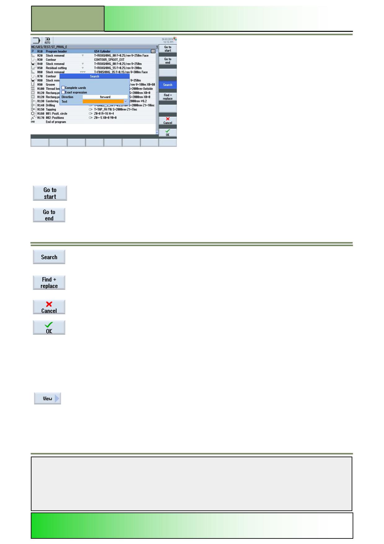
M601
Basics of programming with ShopTurn
Vertical softkey bar
Display area
Description
By pressing the VSK 1 “Go to start” the cursor will be positioned on the first line of the program.
By pressing the VSK 2 “Go to end” the cursor will be positioned on the last line of the program.
By pressing the VSK4 “Search” the search mask opens, where you can decide to search for
complete words or Exact expression, select the search direction (forward/backwards) and enter
the search text.
By pressing the VSK5 “Find + replace” the “Search and replace” mask opens where you can
decide to search for complete words, select the search direction (forward/backwards), enter the
search text and enter the text you want to use for the replacement.
With pressing the VSK 7 “Cancel” you can abort the search process.
By pressing the VSK 8 “OK“ you start a search run with the above mentioned search criteria.
View
With the function “View” you can expand or close all “groups” that have been created in the program.
Selecting the function “View”
By pressing the VSK1.2 “View” the softkeys “Close all blocks” and “Open all blocks” are shown
like displayed below.
Notes
M601
Page 16
828D/840Dsl SINUMERIK Operate
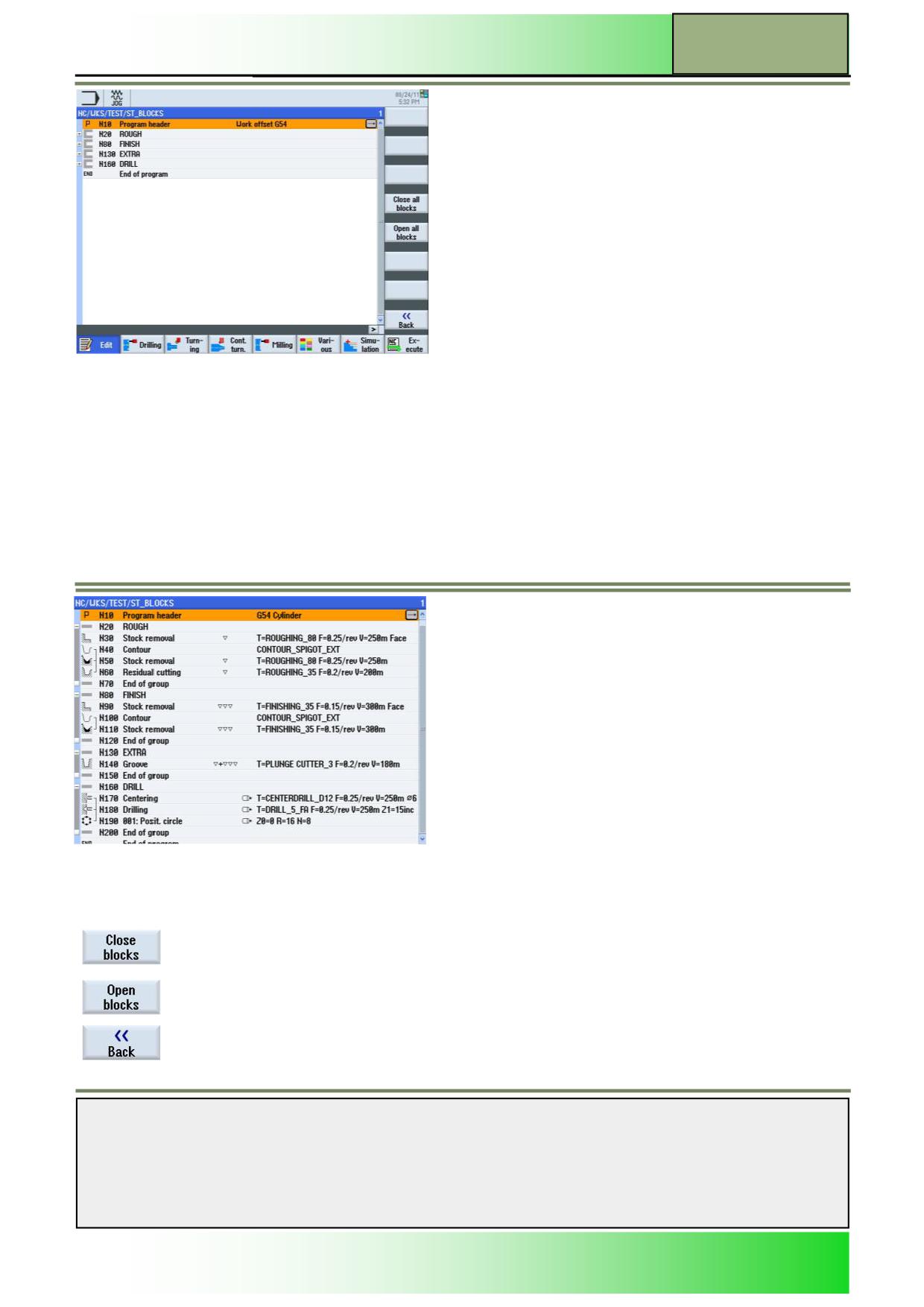
Basics of programming with ShopTurn
M601
Press VSK 5 “Open all blocks”
Vertical softkey bar
Display area
Description
Pressing the VSK 4 “Close blocks” you can close all block in the program.
Pressing the VSK 5 “Open blocks“ you can open all block in the program
With the VSK 8 “Back” you can go back to the previous vertical softkey bar.
Notes
828D/840Dsl SINUMERIK Operate
Page 17
M601
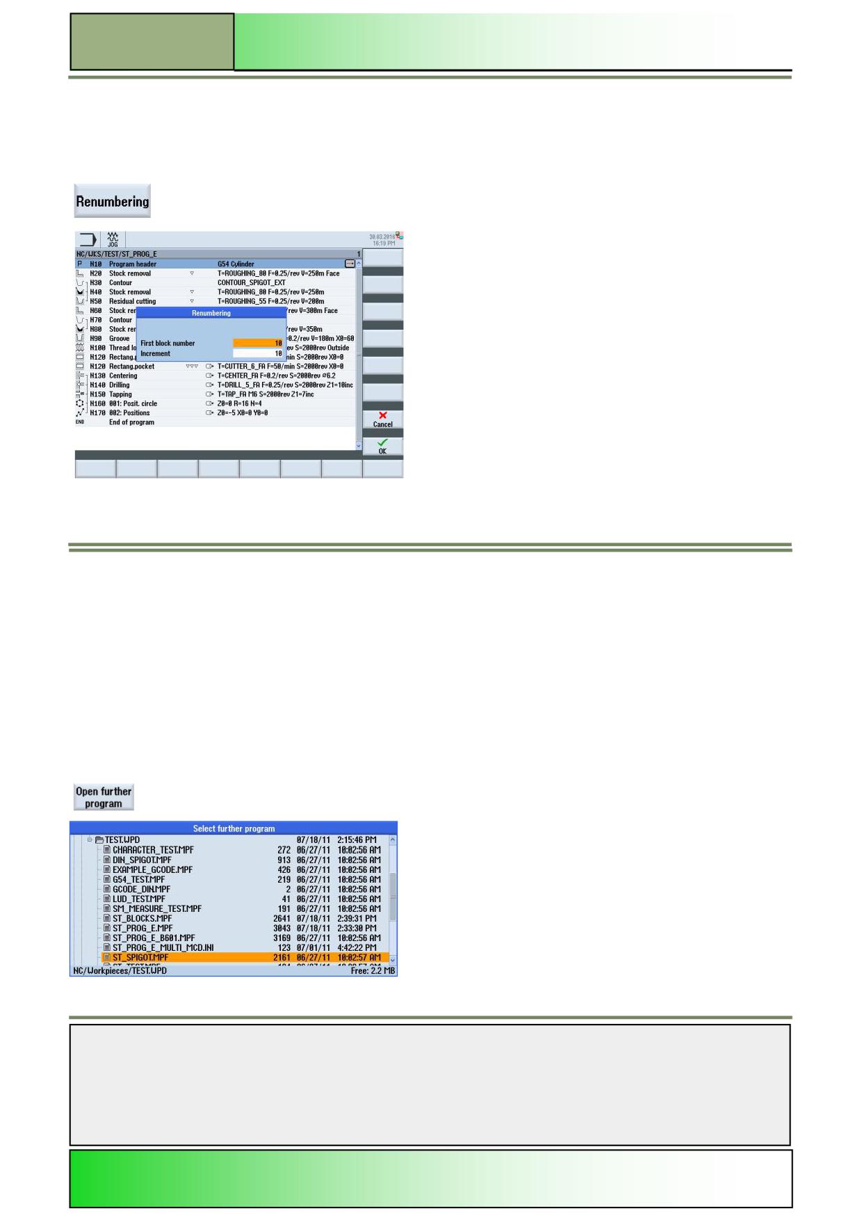
M601
Basics of programming with ShopTurn
Renumbering
With the function “Renumbering” you can renumber the program steps in the editor window with an increment you can se-
lect here.
Selecting the function “Renumbering”
By pressing the VSK 2.3 “Renumbering” the input mask for the renumbering settings of blocks
opens.
Parameters for “Renumbering”
Parameters
Meaning
First block number
The first block number you want to start with.
The values shown here by default can be adjusted under the function “Settings” in the input field
“First block number”.
Increment
The Increment between the program blocks.
The values shown here by default can be adjusted under the function “Settings” in the input field
“Increment”.
Open further programs
With the function “Open further programs” the control will show two programs side by side.
Selecting the function “Open further programs”
By pressing the VSK2.4 “Open further programs” the window opens that allows you to choose
a further program to be shown.
Use the “cursor up” or “cursor down” keys on the key board the select the required program and press VSK8 “OK”
Notes
M601
Page 18
828D/840Dsl SINUMERIK Operate
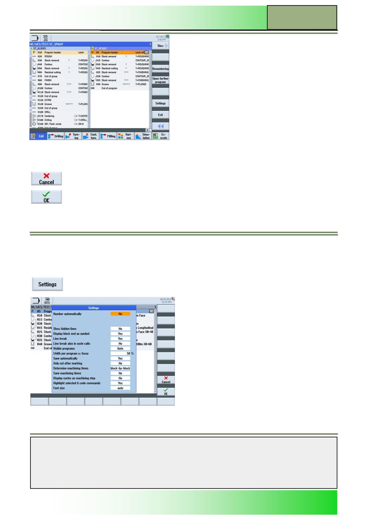
Basics of programming with ShopTurn
M601
Vertical softkey bar
Display area
Description
With pressing the VSK 7 “Cancel” you can abort the select process.
By pressing the VSK 8 “OK“ the control will show two programs side by side, as shown above.
Settings
With the function “Settings” you can change the settings for the editor.
Selecting the function “Settings”
By pressing the VSK2.6 “Settings” the input mask for the editor settings opens.
Notes
828D/840Dsl SINUMERIK Operate
Page 19
M601
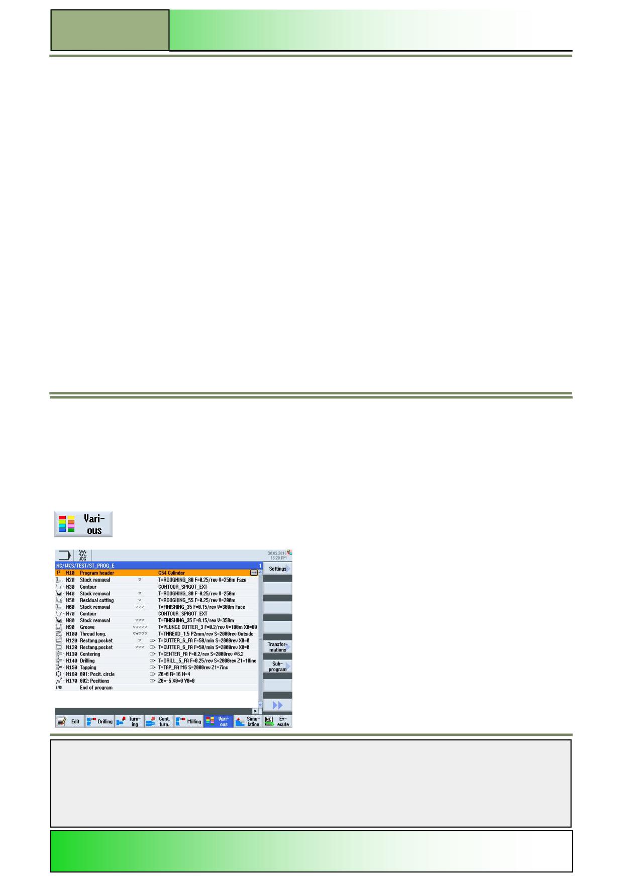
M601
Basics of programming with ShopTurn
Parameters for “Settings”
Parameters
Meaning
Number automatically
Program blocks will be numbered automatically.
(Yes/No)
Deactivating this parameter, hides the following two parameters too.
Show hidden lines
Show hidden line (with the ID ;*HD).
(Yes/No)
Display block end as sym-
A symbol is displayed at the end of each block.
bol (Yes/No)
Line break (Yes/No)
Lines are broken and wrapped around, or a horizontal scrollbar is displayed
Line break also in cycle
If the line of a cycle call becomes too long, then it is displayed over several lines, or the line is
call (Yes/No)
truncated.
Visible programs
Selects how many programs can be displayed next to one another in the editor
Width of program w. focus Here, you enter the width of the selected program in the editor as a percentage of the window
width.
Save automatically
Changes are saved automatically without a query.
(Yes/No)
Only cut after making (yes/
The cutting of program sections is possible only when program lines have been selected or
no)
where the cursor is positioned.
determine machining times Block-by-block / off / Non-modal
Display cycles as machin-
The cycle calls in the G code are displayed as plain text or NC syntax.
ing step (Yes/No)
Highlight selected G code
Selected G code commands or key words can be highlighted in colour
commands
Font size
Defines the font size for the editor and the display of the program sequence
Various
Selecting the function “Various“
The function “Various” can be selected from the operating mode “JOG”, “MDA” or “AUTO” in the operating area “Program”
as follows:
Press the HSK 1.6 “Various“ to switch over to the function “Various”.
A screen similar to the screen shown below opens.
Notes
M601
Page 20
828D/840Dsl SINUMERIK Operate
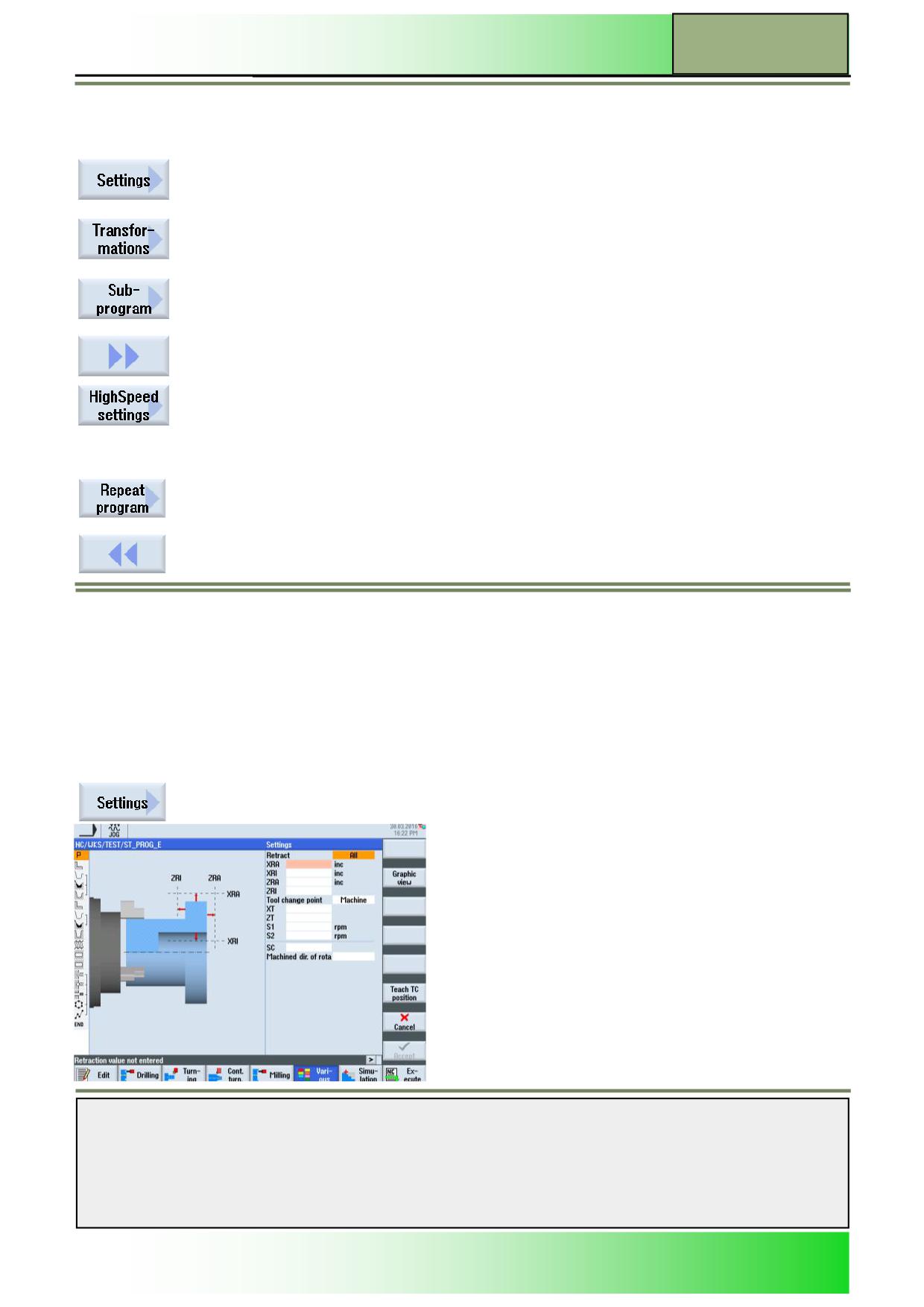
Basics of programming with ShopTurn
M601
Vertical softkey bar 1 and 2
Display area
Description
By pressing the VSK 1.1 “Settings“ an input mask opens where you can change the settings
for the blank.
By pressing the VSK 1.5 “Transformations” the vertical softkey bar with the functions for the
coordinate transformations is displayed.
By pressing the VSK 1.6 “Subprogram” the input mask for loading a subprogram to the main
program opens.
By pressing the VSK 1.8 “Extend“ the vertical softkey bar 2 opens.
By pressing the VSK 2.1 “HighSpeed settings” the input mask for adjusting the settings for
the optimal speed in relation to the machining method opens.
Display area
Description (Continuation)
By pressing the VSK 2.3 “Repeat program” the vertical softkey bar with the function for re-
peating parts of programs opens (see section 5.7).
By pressing the VSK 2.8 “Back“ you switch back to the vertical softkey bar 1.
Settings
Each parameter defined in the program header, except the measuring units, can be changed everywhere in the program.
The settings in the program header are constant, as long as they are not altered later in the program.
For example you can define a new blank in a sequential program later on, if during a simulation run there is the need to
change the visible view on the workpiece. This can be reasonable within the functions “Work offset” “Coordinate transfor-
mation” “Rotational transformation” and “Swivelling”.
With that you can program the above mentioned functions first, and then define the blank afterwards.
The function “Settings” can be opened as follows:
Selecting the function “Settings”
By pressing the VSK 1.1 “Settings” the following window for entering the parameters for the
blank opens.
Notes
828D/840Dsl SINUMERIK Operate
Page 21
M601
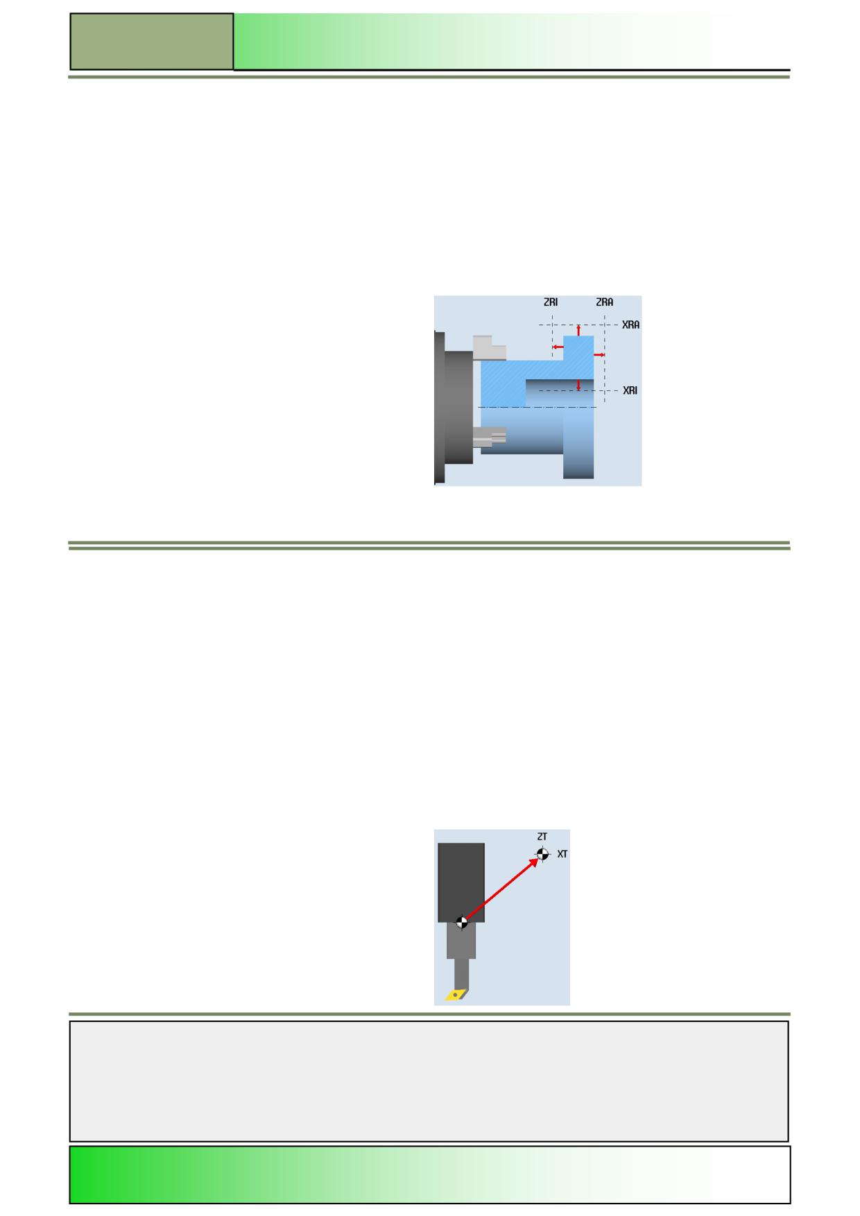
M601
Basics of programming with ShopTurn
Parameters for the function „Settings“
Parameter
Meaning
Help picture/animation
Retract
A changed retraction plane works from the last safety distance set in the cycle, because the
simple
further retraction is carried out by the following cycle.
all
none
XRA (mm)
Retraction plane X related to
XA (ink/abs)
XRI (mm)
Retraction plane X related to
XI (ink/abs)
ZRA (mm)
Retraction plane Z related to
ZA (ink/abs)
ZRI (mm)
Retraction plane Z related to
rear (only if Retract “all” is
selected)
Tailstock
Only if available on the machine.
Tailstock is shown within the simulation and the simultaneous recording window. While ap-
yes
proaching and retracting the retraction logic is considered.
no
You can further expand the retraction area so that collisions with the tailstock will be avoided
XRR (mm)
when traversing the axes (only if Tailstock “Yes” is selected).
Tool change point
Workpiece
Workpiece coordinate system (WCS)
Machine
Machine coordinate system (MCS)
XT (mm)
Tool change point X
ZT (mm)
Tool change point Z
Notes
M601
Page 22
828D/840Dsl SINUMERIK Operate
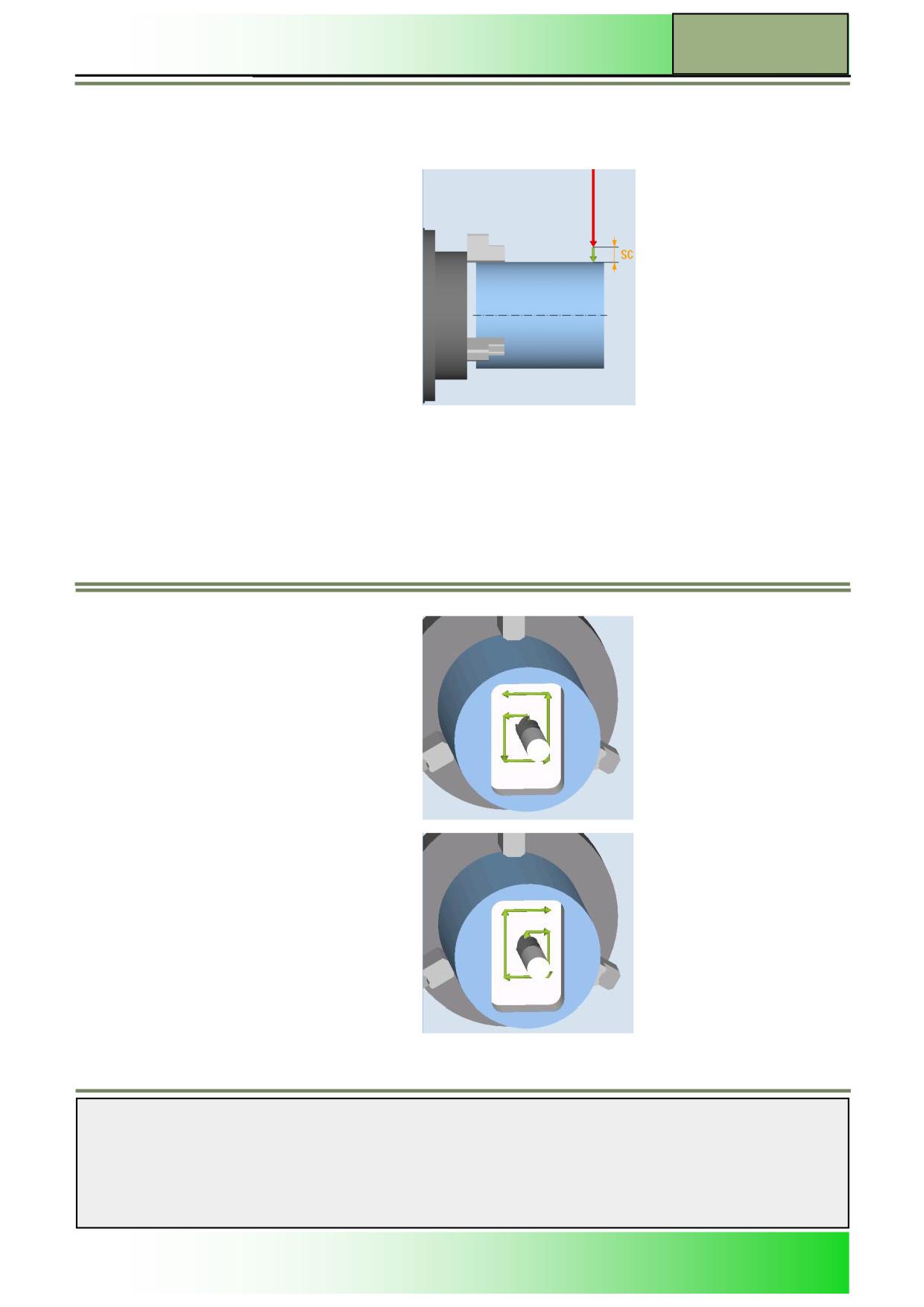
Basics of programming with ShopTurn
M601
Parameter
Meaning
Help picture/animation (continuation)
Safety distance:
The safety distance is
SC (mm)
depending on the refer-
ence point.
The direction is automati-
cally determined by the
cycle.
Speed limits:
S1 (rpm)
Maximum speed of the main spindle
Machining sense:
The machining sense (down cut, up cut) is defined as the moving direction of the cutter tooth in relation to the workpiece.
ShopTurn evaluates the parameter “Machining sense” in relation to the rotation direction of the spindle for milling (except
path milling).
The basic settings for the machining sense is set in a machine datum.
Milling direction, counter
Down cut
clockwise
Up cut
Milling direction, clockwise
Notes
828D/840Dsl SINUMERIK Operate
Page 23
M601