SINUMERIK 840D sl. Training. Operate - Turning (2016-2020) - page 18
Contour milling with ShopMill
M623
37.
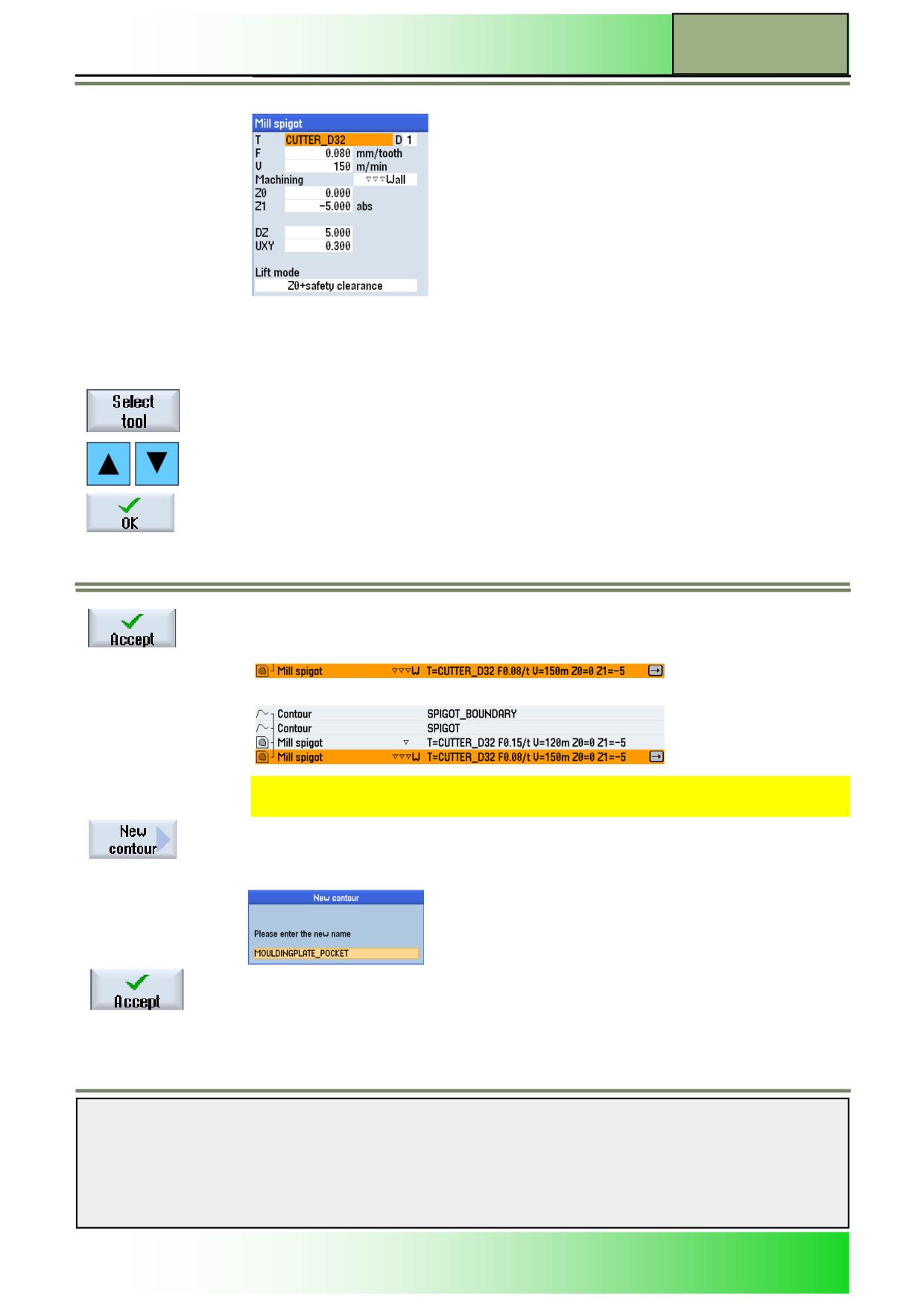
Insert the following parameter values. Use the blue “Select” key where indicated.
Note:
In the input field “F” you can switch between
“mm/tooth” or “mm/min” . The input field for Speed can either be set to cutting speed “V” in “m/
min” or Spindle speed “S” in “rpm”.
The machining depth “Z1” can be “inc” or “abs”.
To insert a tool into the cycle input mask, press the VSK 1 “Select tool”.
The “Tool selection” list window opens.
Use the blue cursor keys on the keyboard, to mark the tool “CUTTER_D32”, with the orange
selection cursor.
Press the VSK 1.8 “OK”.
The tool “CUTTER_D32" will be inserted into the cycle input mask.
Confirm your inputs by pressing the VSK 8 “Accept”.
The following program block will be added to the program chain.
The program chain is now complete and closed.
38.
Start programming the contour description for the “Moulding plate pocket” with help of the
contour editor.
Press the VSK 1 “New contour”.
A parameter mask where you can enter a name for the new contour opens.
Enter a name for the new contour, e.g. “MOULDINGPLATE_POCKET”.
Confirm your input by pressing the VSK 8 “Accept”.
Notes
828D/840Dsl SINUMERIK Operate
Page 19
M623
M623
Contour milling with ShopMill
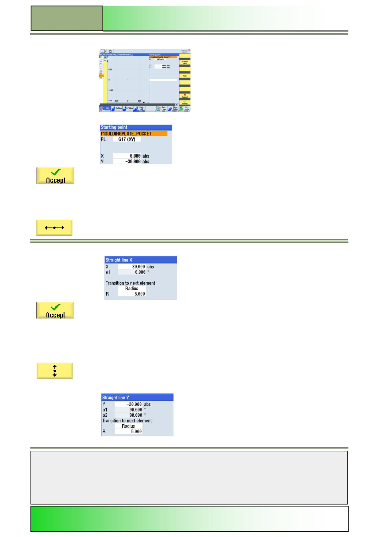
The contour editor opens automatically and the parameter mask for entering a start point for the
contour is active by default.
39.
Enter the following coordinates for the starting point:
Press the VSK 8 “Accept” to confirm your inputs.
The contour description starts and new functions
for defining a contour are available as yellow vertical softkeys on the right side of the screen.
40.
Begin the contour description by adding a straight line in X-direction.
Press the VSK 1.2 “Straight line X”.
The input window for the “Straight line X” opens.
Insert the following values into the parameter mask.
Press the VSK 8 “Accept” to confirm your inputs.
The first Kontur element is generated and a straight
line in X-direction is added to your contour description.
41.
Extend the contour description by adding a straight line in Y-direction.
Press the VSK 3 “Straight line Y”.
The input window for the “Straight line Y” opens.
Insert the following values into the parameter mask.
Notes
M623
Page 20
828D/840Dsl SINUMERIK Operate
Contour milling with ShopMill
M623
Press the VSK 8 “Accept” to confirm your inputs.
A straight line in Y-direction is added to your contour description.
42.
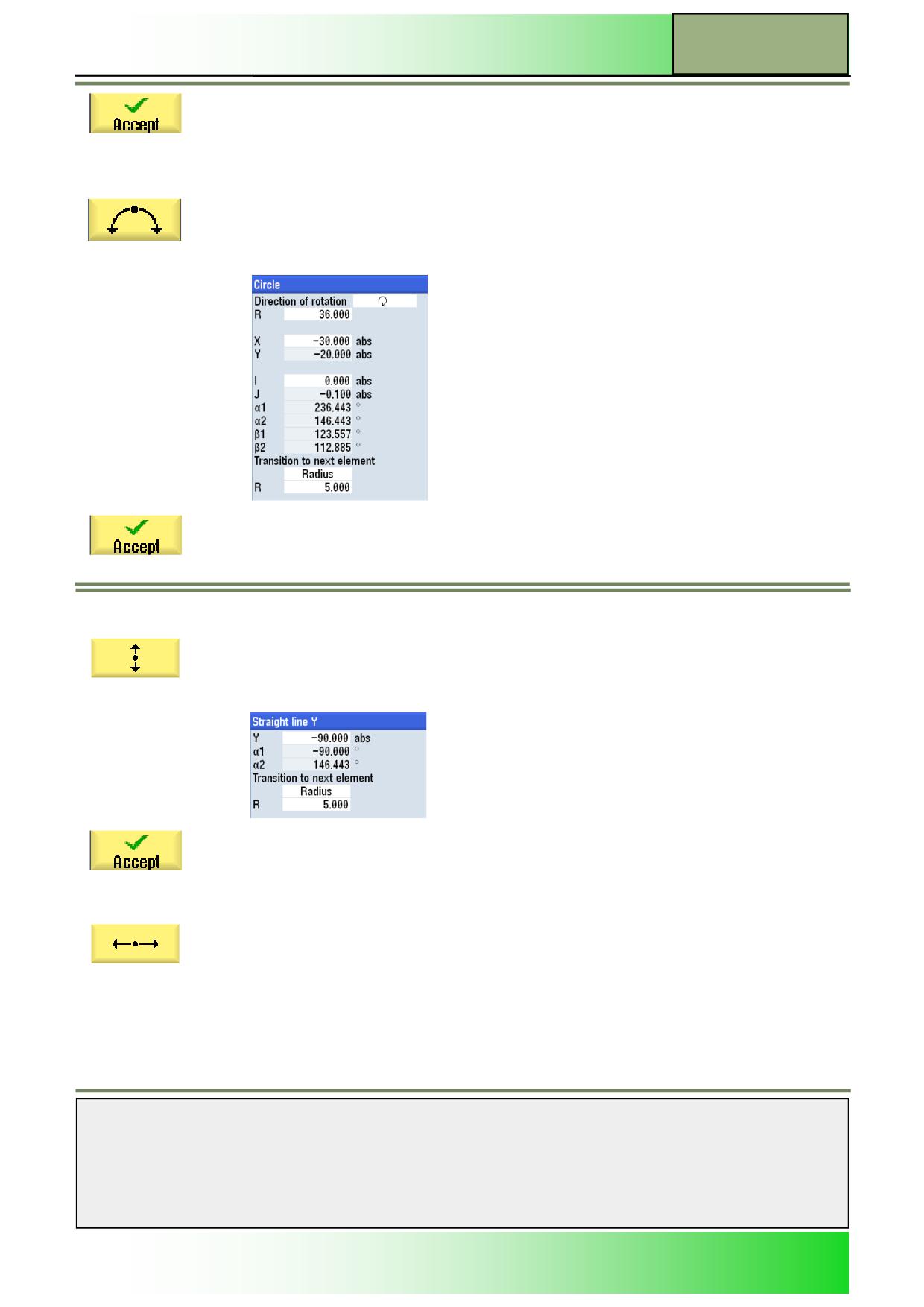
Extend the contour description by adding a circle in clockwise direction.
Press the VSK 5 “Circle”.
The input window for the “Circle” opens.
Enter following coordinates into the parameter mask:
Confirm the VSK 8 “Accept”.
A circle in clockwise direction is added to your contour description.
43.
Extend the contour description by adding a straight line in Y-direction.
Press the VSK 3 “Straight line Y”.
The input window for the “Straight line Y” opens.
Insert the following values into the parameter mask.
Confirm the VSK 8 “Accept”.
A straight line in Y-direction is added to your contour description.
44.
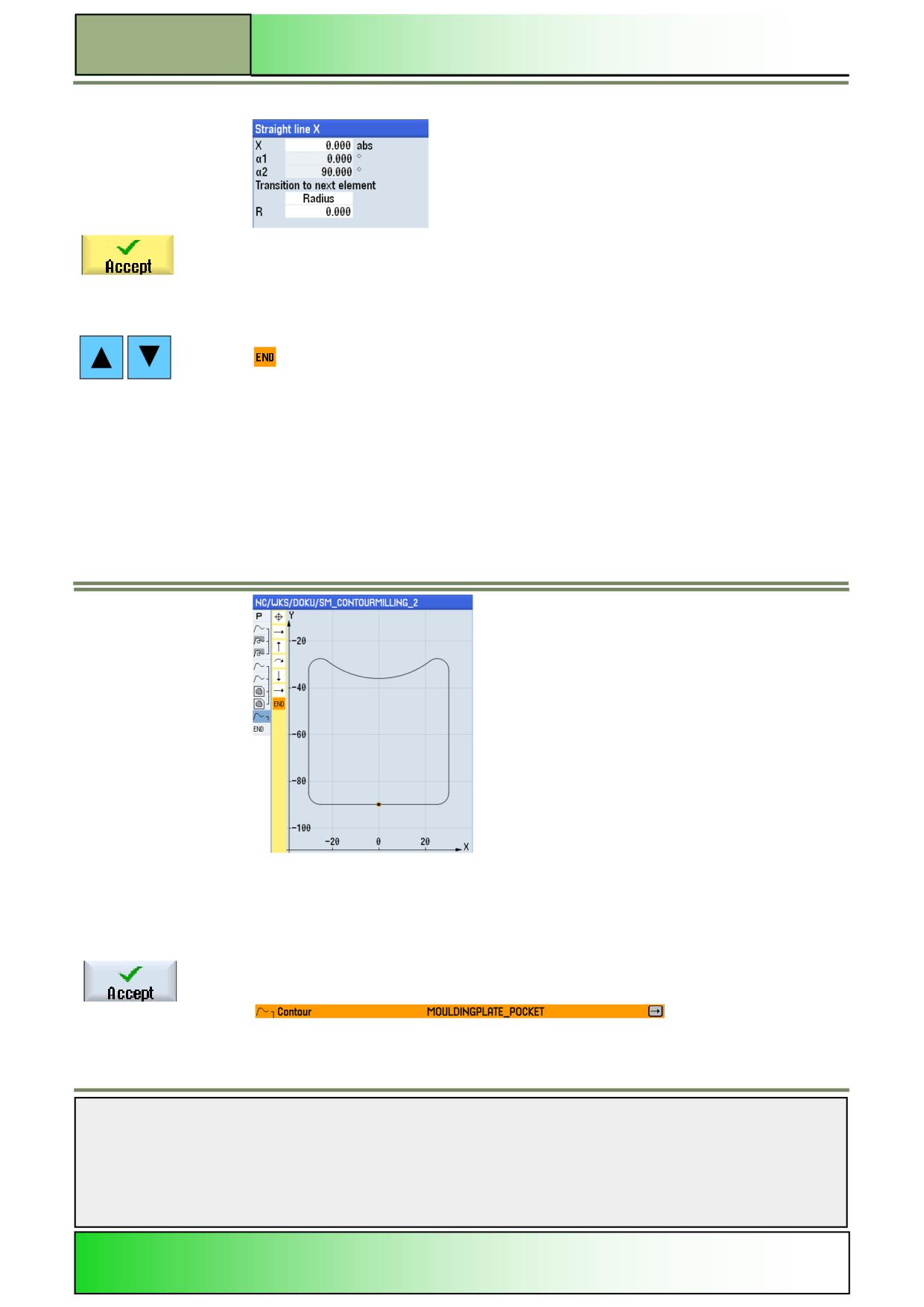
Now finish the programming of the contour path by adding a straight line in X-direction.
Press the VSK 2 “Straight line X”.
The input window for the “straight line X” opens.
Notes
828D/840Dsl SINUMERIK Operate
Page 21
M623
M623
Contour milling with ShopMill
Enter following coordinates into the parameter mask:
Confirm your inputs by pressing the VSK 8 “Accept”.
The contour description is now closed by a straight line in Y-direction and therefore finished.
45.
Now, check the outline of the contour path.
For this, place the orange selection cursor on the
-symbol in the yellow column on the left side of the screen, by using the blue cursor keys on
the keyboard.
The contour is displayed graphically.
Note:
The white column on the left side of the help screen shows all the program blocks programmed
as symbols (representing the technology). The yellow column next to it shows all the pro-
grammed contour elements as symbols.
46.
Finish now the programming of the contour by pressing the VSK 8 “Accept”.
The program editor opens and the following program block is inserted into the program:
The program chain opens.
Notes
M623
Page 22
828D/840Dsl SINUMERIK Operate
Contour milling with ShopMill
M623
47.
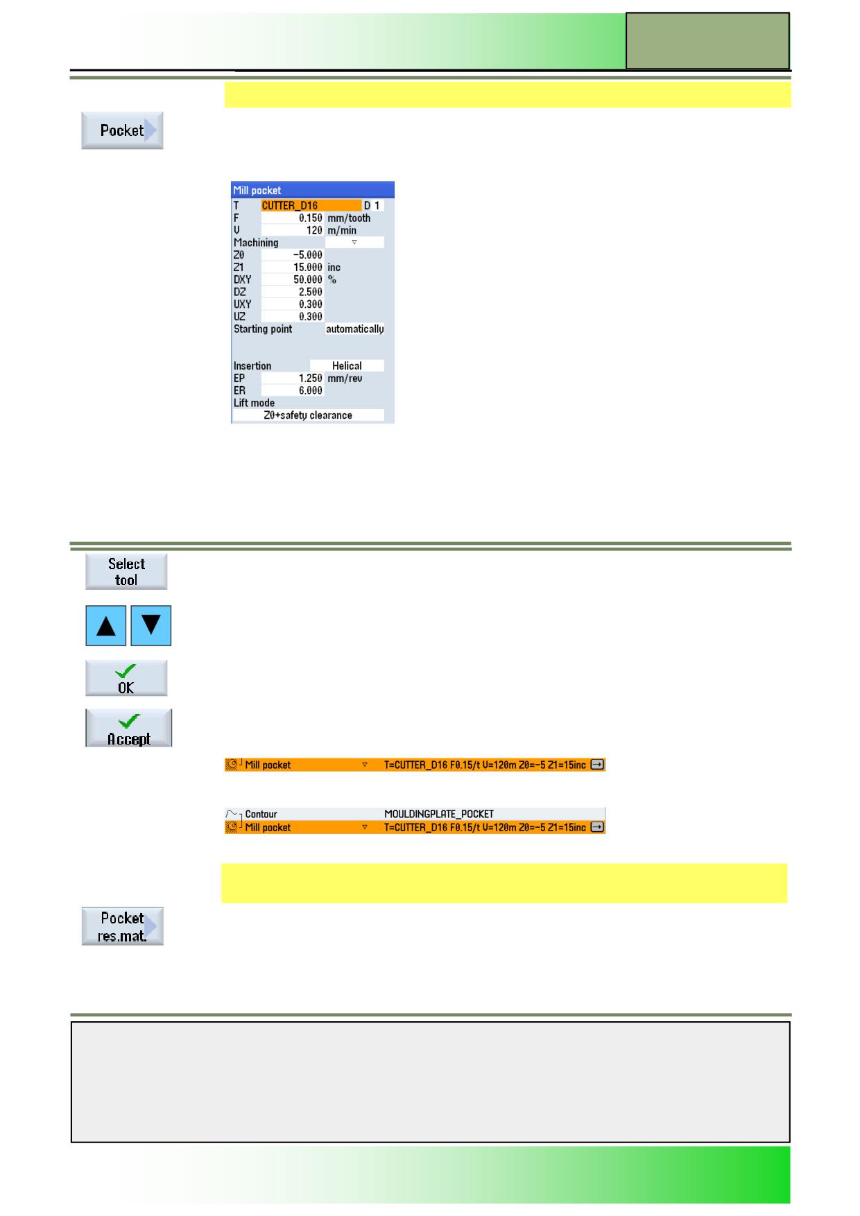
Insert now a “pocket milling” cycle into the program for “roughing” the moulding plate pocket.
Press the VSK 1.4 “Pocket”.
The input window for the pocket milling cycle opens.
48.
Insert the following parameter values. Use the blue “Select” key where indicated.
Note:
In the input field “F” you can switch between
“mm/tooth” or “mm/min” . The input field for Speed can either be set to cutting speed “V” in “m/
min” or Spindle speed “S” in “rpm”.
The machining depth “Z1” can be “inc” or “abs”.
The tool path step over “DXY” can be set to “%” of tool Ø or a value in “mm” .
To insert a tool into the cycle input mask, press the VSK 1 “Select tool”.
The “Tool selection” list window opens.
Use the blue cursor keys on the keyboard, to mark the tool “CUTTER_D16”, with the orange
selection cursor.
Press the VSK 1.8 “OK”.
The tool “CUTTER_D16" will be inserted into the cycle input mask.
Confirm your inputs by pressing the VSK 8 “Accept”.
The following program block will be added to the program chain.
The program chain closes.
49.
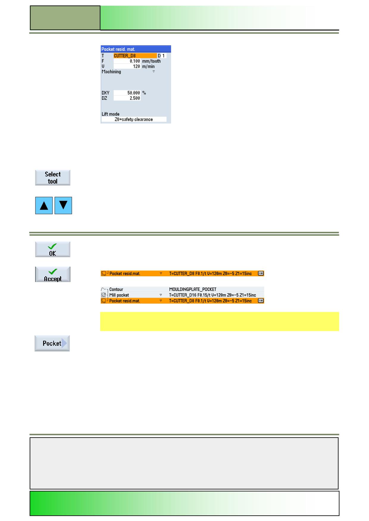
Extend the program chain by inserting a “Pocket residual material” cycle for “roughing” of the
residual material of the moulding plate pocket.
Press the VSK 1.5 “Pocket resid. mat.”.
The input window for the pocket residual material cycle opens.
Notes
828D/840Dsl SINUMERIK Operate
Page 23
M623
M623
Contour milling with ShopMill
50.
Insert the following parameter values. Use the blue “Select” key where indicated.
Note:
In the input field “F” you can switch between
“mm/tooth” or “mm/min” . The input field for Speed can either be set to cutting speed “V” in “m/
min” or Spindle speed “S” in “rpm”.
The tool path step over “DXY” can be set to “%” of tool Ø or a value in “mm” .
To insert a tool into the cycle input mask, press the VSK 1 “Select tool”.
The “Tool list” window opens.
Use the blue cursor keys on the keyboard, to mark the tool “CUTTER_D8”, with the orange
selection cursor.
Press the VSK 1.8 “OK”.
The tool “CUTTER_D8" will be inserted into the cycle input mask.
Confirm your inputs by pressing the VSK 8 “Accept”.
The following program block will be added to the program chain.
51.
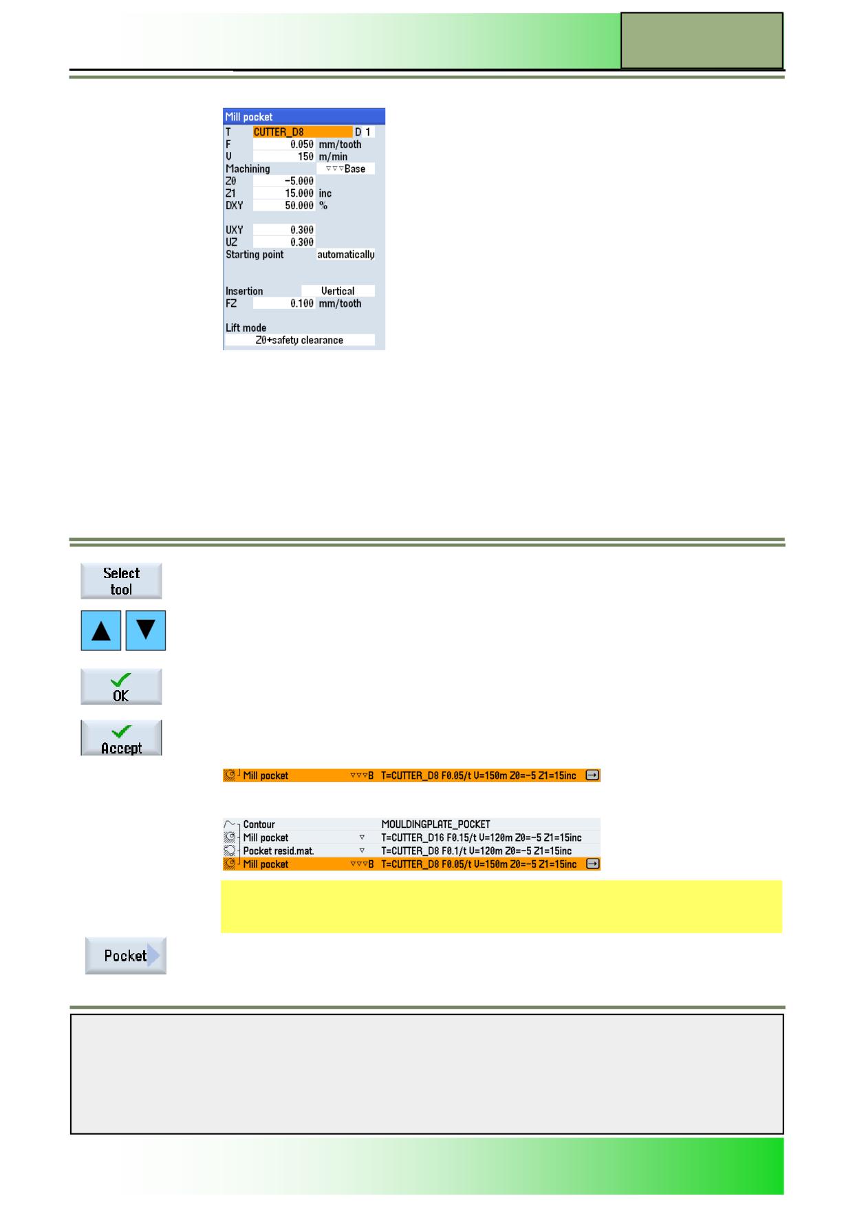
Extend the program chain by inserting another “Pocket milling” cycle for “finishing” the
“base” of the moulding plate pocket.
Press the VSK 1.4 “Pocket”.
The input window for the pocket milling cycle opens.
Notes
M623
Page 24
828D/840Dsl SINUMERIK Operate
Contour milling with ShopMill
M623
52.
Insert the following parameter values. Use the blue “Select” key where indicated.
Note:
In the input field “F” you can switch between
“mm/tooth” or “mm/min” . The input field for Speed can either be set to cutting speed “V” in “m/
min” or Spindle speed “S” in “rpm”.
The machining depth “Z1” can be “inc” or “abs”.
The tool path step over “DXY” can be set to “%” of tool Ø or a value in “mm” of the tool Ø.
To insert a tool into the cycle input mask, press the VSK 1 “Select tool”.
The “Tool list” window opens.
Use the blue cursor keys on the keyboard, to mark the tool “CUTTER_D8”, with the orange se-
lection cursor.
Press the VSK 1.8 “OK”.
The tool “CUTTER_D8" will be inserted into the cycle input mask.
Confirm your inputs by pressing the VSK 8 “Accept”.
The following program block will be added to the program chain.
The program chain is closed.
53.
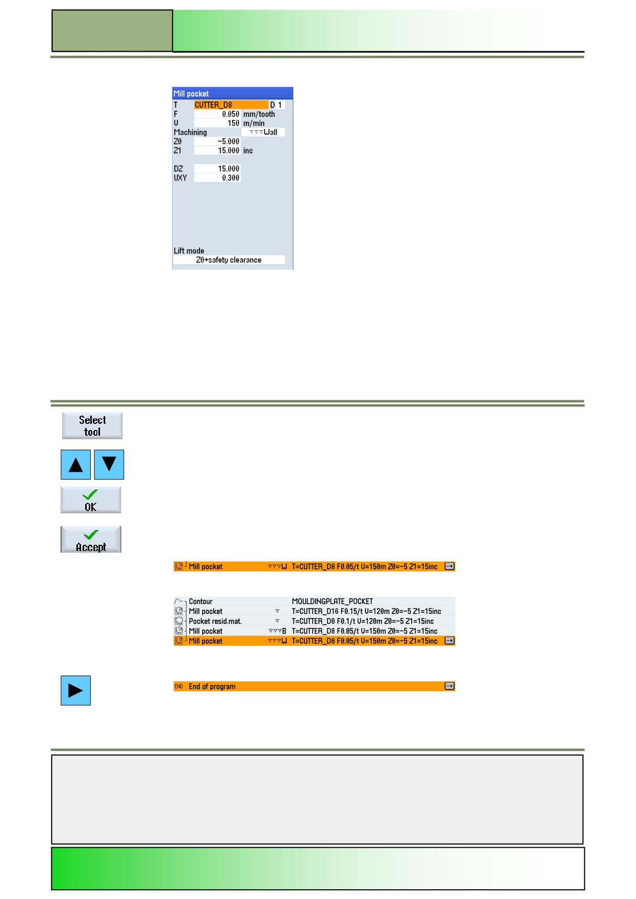
Insert another “Pocket milling” cycle into the program for “finishing” the “base” of the mould-
ing plate pocket.
Press the VSK 1.4 “Pocket”.
The input window for the pocket milling cycle opens.
Notes
828D/840Dsl SINUMERIK Operate
Page 25
M623
M623
Contour milling with ShopMill
54.
Insert the following parameter values. Use the blue “Select” key where indicated.
Note:
In the input field “F” you can switch between
“mm/tooth” or “mm/min” . The input field for Speed can either be set to cutting speed “V” in “m/
min” or Spindle speed “S” in “rpm”.
The machining depth “Z1” can be “inc” or “abs”.
To insert a tool into the cycle input mask, press the VSK 1 “Select tool” .
The “Tool selection” list window opens.
Use the blue cursor keys on the keyboard, to mark the tool “CUTTER_D8”, with the orange
selection cursor.
Press the VSK 1.8 “OK”.
The tool “CUTTER_D8" will be inserted into the cycle input mask.
Confirm your inputs by pressing the VSK 8 “Accept”.
The following program block will be inserted into the program.
The program chain is now finished and closed.
55.
End the programming by placing the orange selection cursor on the program block “End of
program”
and switch to the parameter mask by pressing the blue “cursor-to-the-right”-key on the key-
board.
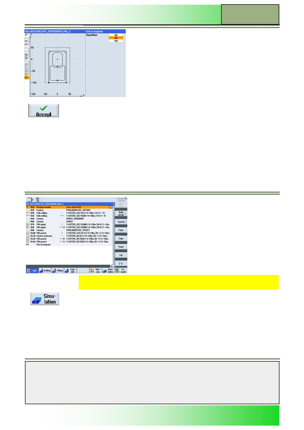
The parameter mask for the program end opens, where you can define to repeat the program
for multiple workpieces.
Notes
M623
Page 26
828D/840Dsl SINUMERIK Operate
Contour milling with ShopMill
M623
Accept the default value “No” and press the VSK 8 “Accept”.
The program is now completed and ready for simulation.
54.
Simulate now the program to verify tool path.
Press the HSK 1.7 “Simulation” to start the simulation.
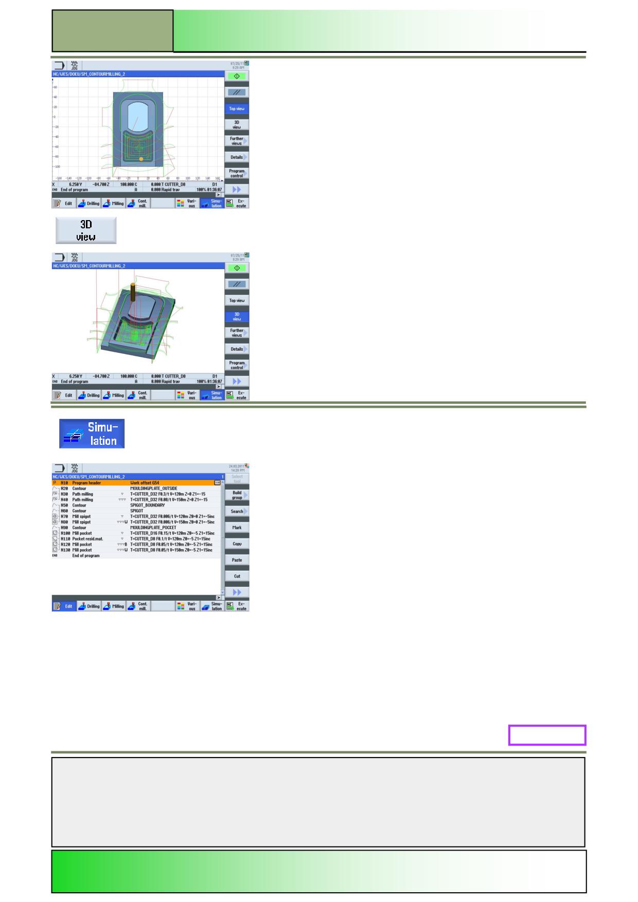
The control calculates the simulation and opens the simulation window in a “Top view” on the
workpiece.
Notes
828D/840Dsl SINUMERIK Operate
Page 27
M623
M623
Contour milling with ShopMill
Press the VSK 1.4 “3D view“ to run the simulation in a 3-dimensional view.
Press the blue highlighted HSK 1.7 “Simulation" to return to the ShopMill chain program.
After completion of the workpiece Simulation, the Total machining time is being displayed behind
the „End of program“ program block
Note:
The total time represents approximately the real time of machining. Tool change time and rapid
traverse movements are being taken into consideration based on the values in the machine data.
M623: END
Notes
M623
Page 28
828D/840Dsl SINUMERIK Operate
M639
Straight Circle with ShopMill
Sinumerik
Operate
Module Description:
This module explains the programming of a simple program using the straight circle technology in
ShopTurn, by means of chained straight circle cycles.
Module Objective:
Working with this module you become familiar with the technology “Straight Circle” in
ShopMill with the programming of a sequential ShopMill programs.
Content:
Programming example
This document was produced for training purposes.
828D/840Dsl SINUMERIK Operate v4.7
Page 1
M639
Siemens assumes no responsibility for its contents.
M639
M639
Page 2
828D/840Dsl SINUMERIK Operate
Straight Circle with ShopMill
M639
Straight
Circle:
START
Programming
example
Straight
Circle:
END
Notes
828D/840Dsl SINUMERIK Operate
Page 3
M639
M639
Straight Circle with ShopMill
Programming example
Description:
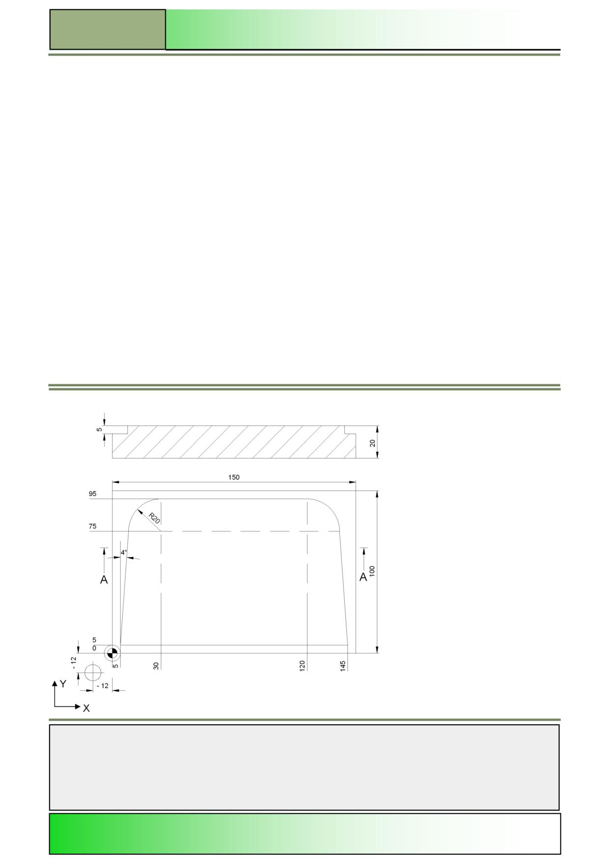
A program (die plate) is to be programmed, by using the technology “Straight Circle”.
Aim:
The workpiece shown in the graphic below is to be programmed.
Afterwards the program is to be simulated.
The following tool and technology data are used for the programming.
Tool data:
Cutter Ø 20 mm (CUTTER_D20)
:
Technology data:
Constant cutting speed V 80 m/min
:
As starting point for the machining the following position is specified:
X
- 12
Y
- 12
Z
- 5
This point is approached in rapid traverse.
The contour starting point (X5 and Y5) is approached in a straight line (F 100 mm/min, cutter
radius compensation left).
Notes
M639
Page 4
828D/840Dsl SINUMERIK Operate
Straight Circle with ShopMill
M639
Programming example: die plate
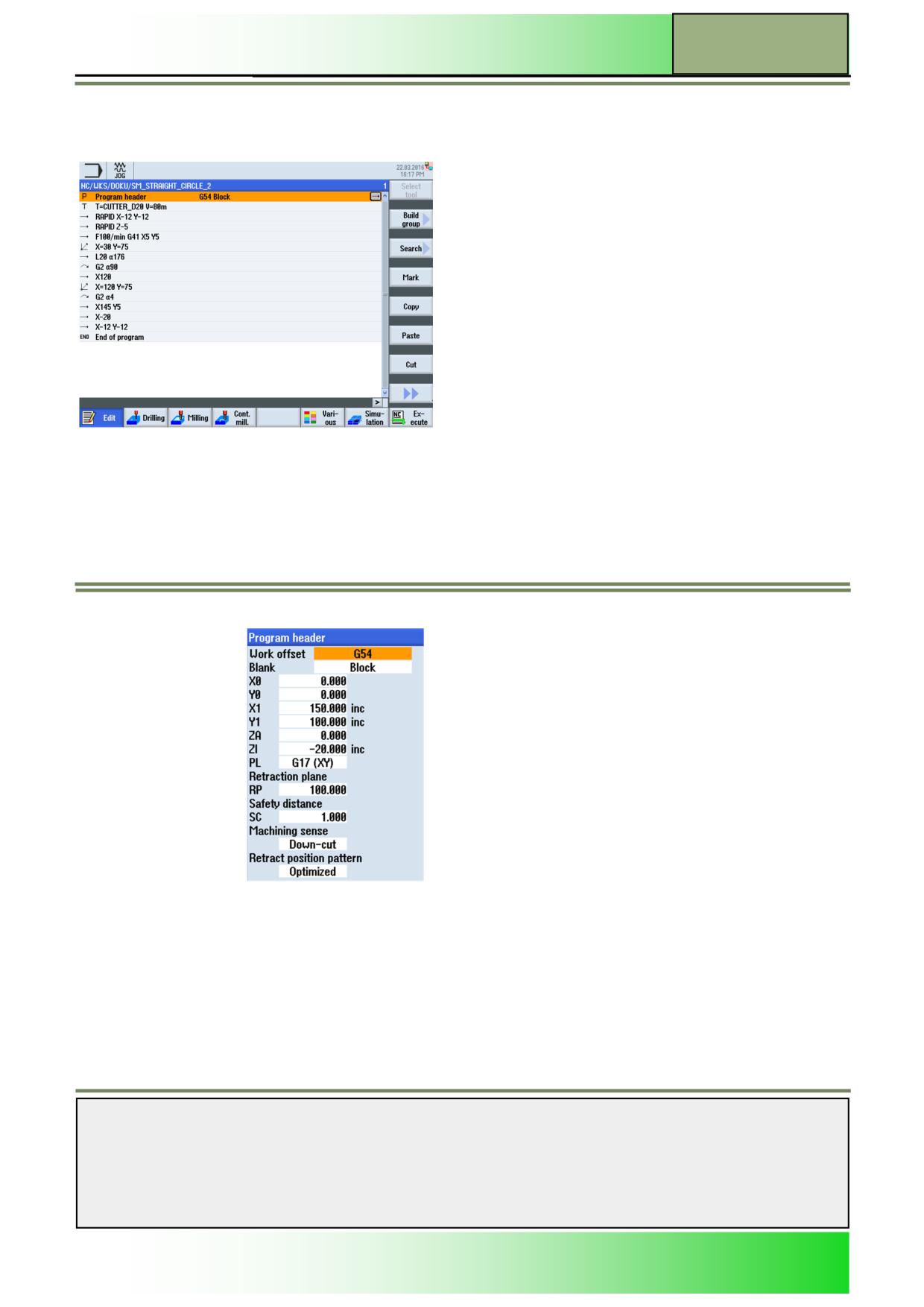
The following ShopMill program is to be created.
1.
Create a new ShopMill program.
Give the program the following name: “SM_STRAIGHT_CIRCLE_2.MPF“.
The program, with the input mask for the program header opens by default.
2.
Enter the following values into the program header:
Notes
828D/840Dsl SINUMERIK Operate
Page 5
M639
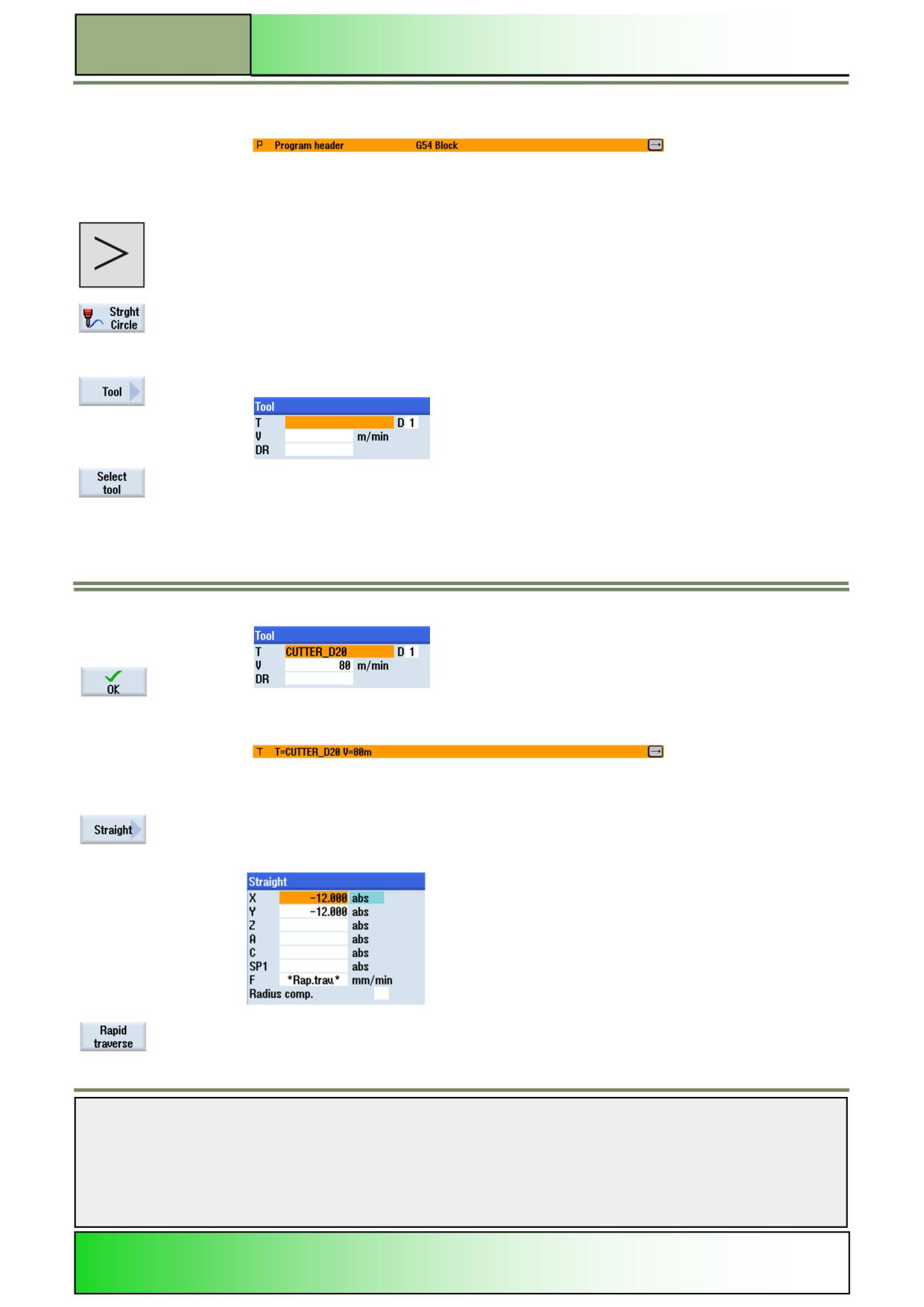
M639
Straight Circle with ShopMill
3.
Confirm your inputs by pressing the VSK 8 „Accept“.
The following program block is inserted into the work plan:
4.
Inset now a tool (CUTTER_D20) into the program.
In order to do this, switch to the horizontal softkey bar 2, by pressing the “Extend” key on the
operator panel.
The horizontal softkey bar 2 opens.
Press the HSK 2.2 “Strght Circle” to select the function “Straight Circle”.
The operating area of the function “Straight Circle” opens.
Now press the VSK 1 “Tool” to open the input mask for the tool (see picture below).
To insert a tool into the parameter mask, press the VSK 1 “Select tool”. The tool list window
opens.
Here, place the orange selection cursor on the tool “CUTTER_D20”, by using the blue cursor
keys on the keyboard and press the VSK 1.8 “OK”.
The selected tool is inserted into the tool input mask like displayed below
5.
Fill out the rest of the input mask, as follows:
Confirm your inputs by pressing the VSK 8 “Accept”.
The following program block is inserted into the work plan:
6.
Position now the tool to the starting position of the machining operation in a straight line.
Press the VSK 2 “Straight” to open the input mask for the function “Straight”.
7.
Insert the following values into input mask:
Press the VSK 5 “Rapid traverse” in order to position to the starting point in rapid traverse.
Notes
M639
Page 6
828D/840Dsl SINUMERIK Operate
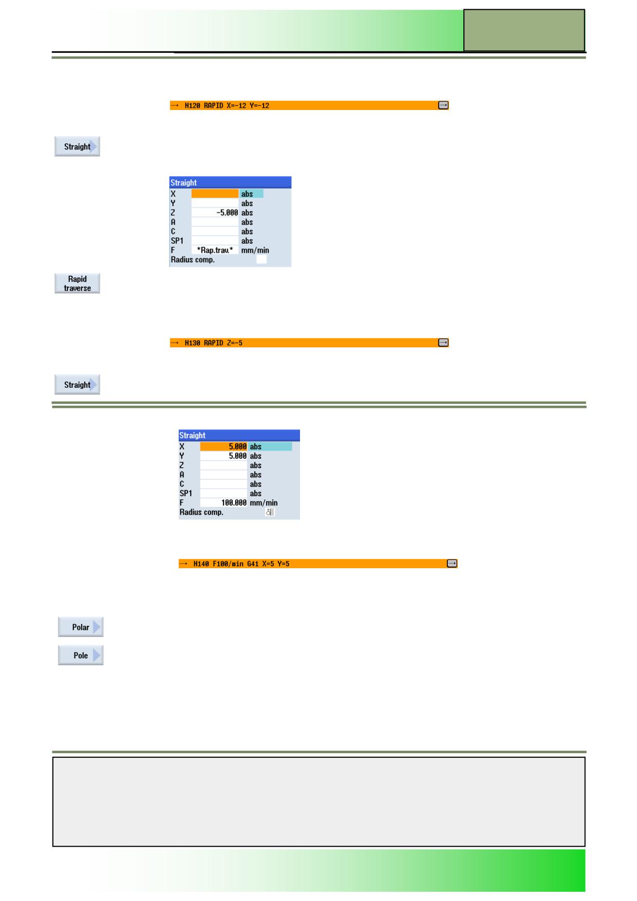
Straight Circle with ShopMill
M639
Confirm your inputs by pressing the VSK 8 “Accept”.
The following program block is inserted into the program:
8.
Insert now another straight move into the program.
Press the VSK 2 “Straight” to open the input mask for the function “Straight”.
9.
Insert the following values into the input mask:
Press the VSK 5 “Rapid traverse”, in order to move to the Z depth in rapid traverse.
Confirm your inputs by pressing the VSK 8 “Accept”.
The following program block is inserted into the program:
10.
Insert now another Straight move into the program.
Press the VSK 2 “Straight” to open the input mask for the function “Straight”.
11.
Insert the following values into the parameter window:
Confirm your inputs by pressing the VSK 8 “Accept”.
The following program block is inserted into the program:
12.
Define now the reference point of the polar coordinate system (pole) for the technology
“Straight circle”.
Press the VSK 6 „Polar“ to open the input window for the function “Polar”.
Press the VSK 2 „Pole“ to open the input mask for the function “Pole”.
Notes
828D/840Dsl SINUMERIK Operate
Page 7
M639
M639
Straight Circle with ShopMill
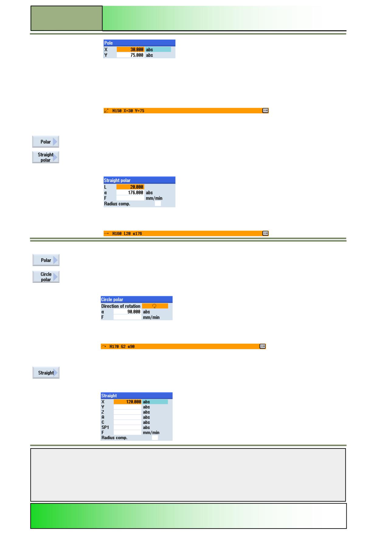
13.
Define the pole as follows:
Confirm your inputs by pressing the VSK 8 “Accept”.
The following program block is inserted into the program:
14.
Insert now a “Straight polar” move into the program.
Press the VSK 6 „Polar“ to open the input window for the function “Polar”.
Press the VSK 3 “Straight polar“ to open the input mask for the function “Straight polar”.
15.
Enter the values as follows:
Confirm your inputs by pressing the VSK 8 “Accept”.
The following program block is inserted into the work plan:
16.
Insert another “Circle polar” move into the program.
Press the VSK 6 „Polar“ to open the operating area for the function „Polar“.
Press the VSK 4 „Circle polar“, the input mask for the circle polar opens.
17.
Enter the values into the input window like displayed below:
Confirm your inputs by pressing the VSK 8 “Accept”.
The following program block is inserted into the work plan:
18.
Insert now a straight machining movement.
Press the VSK 2 „Straight“ to open the input window.
19.
Enter the values into the input window like displayed below:
Notes
M639
Page 8
828D/840Dsl SINUMERIK Operate
Straight Circle with ShopMill
M639
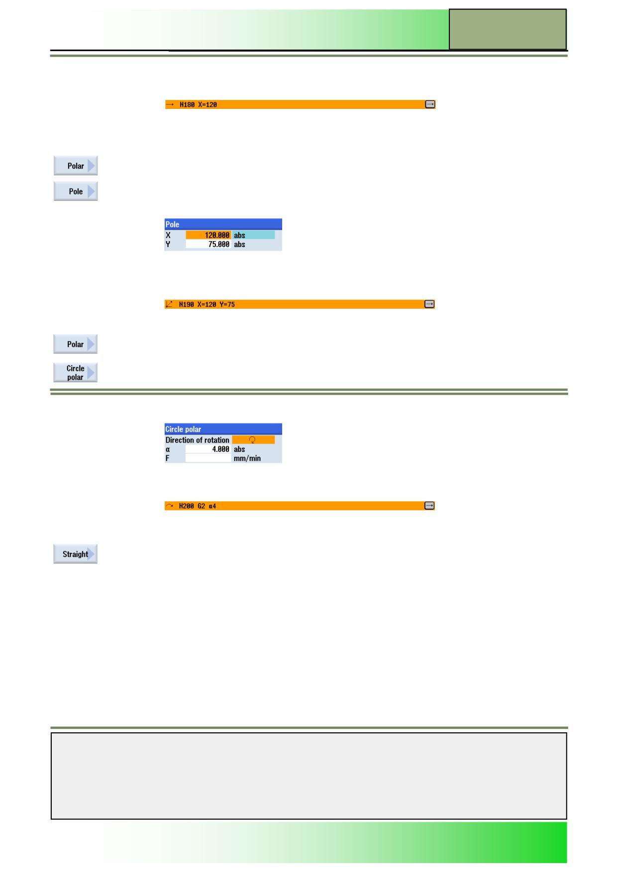
Confirm your inputs by pressing the VSK 8 “Accept”.
The following program block is inserted into the work plan:
20.
Define now a second reference point of the polar coordinate system (pole) for the technology
“Straight circle”.
Press the VSK 6 „Polar“ to open the input mask for the function „Polar“.
Press the VSK 2 „Pole” to open the input mask for the function „Pole“.
21.
Enter the values into the input mask as displayed below:
Confirm your inputs by pressing the VSK 8 “Accept”.
The following program block is inserted into the work plan:
22.
Insert another „Circle polar“ move into the program.
Press the VSK 6 „Polar“ to open the operating area for the function „Polar“.
Press the VSK 4 „Circle polar“, to open the input mask for “Circle polar”.
23.
Enter the values into the input mask as displayed below:
Confirm your inputs by pressing the VSK 8 “Accept”.
The following program block is inserted into the work plan:
24.
Insert now a straight machining movement.
Press the VSK 2 „Straight“ to open the input window.
Notes
828D/840Dsl SINUMERIK Operate
Page 9
M639
M639
Straight Circle with ShopMill
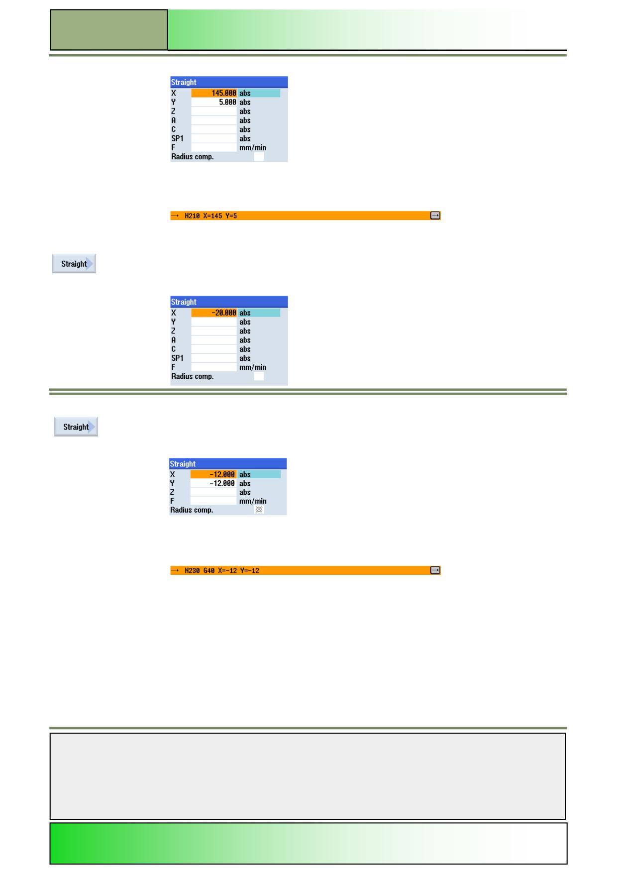
25.
Enter the values into the input mask as displayed below:
Confirm your inputs by pressing the VSK 8 “Accept”.
The following program block is inserted into the work plan:
26.
Insert another “Straight” machining movement into the program.
Press the VSK 2 „Straight“ to open the input mask for the function “Straight”.
27.
Enter the values into the input mask as displayed below:
28.
Insert the final straight machining movement into the program.
Press the VSK 2 „Straight“ to open the input window.
29.
Enter the values into the input mask as displayed below:
Confirm your inputs by pressing the VSK 8 “Accept”.
The following program block is inserted into the work plan:
30.
Program the end of the program and simulate the machining.
Place the orange selection cursor on the program block “End of program” and extend the pro-
gram block by pressing the blue “cursor-to-the-right” key on the keyboard.
Notes
M639
Page 10
828D/840Dsl SINUMERIK Operate
Straight Circle with ShopMill
M639
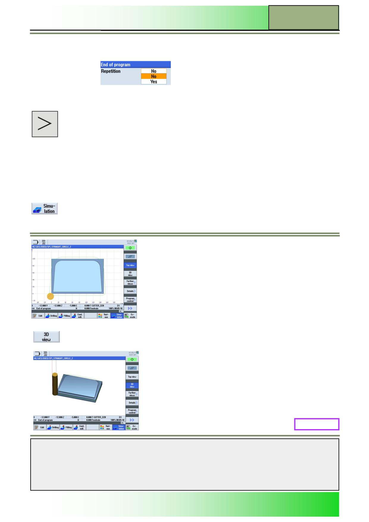
The input mask for the program end opens.
Leave the parameter “Repetition” on “No” as shown below.
Accept the default value by pressing the VSK 8 “Accept”.
31.
To run the simulation go back to the horizontal softkey bar 1.
Extend the horizontal softkey bar by pressing the “Extend” key on the operator panel.
The horizontal softkey bar 1 opens.
Press the HSK 1.7 “Simulation” to start the simulation of the program.
The control calculates the simulation parameters and opens the simulation in the simulation
window in “Top view”.
To view the simulation 3-dimensional press the VSK 1.4 “3D view”.
M639: END
Notes
828D/840Dsl SINUMERIK Operate
Page 11
M639

M639
Straight Circle with ShopMill
Notes
M639
Page 12
828D/840Dsl SINUMERIK Operate
M604
Basics of programming with the program-
Sinumerik
GUIDE
Operate
Module Description:
This module explains the general program structure of a ShopMill G code program, programmed with
the programGUIDE. Furthermore the functions of the “Editor“ are described, as well as the functions
“Various “.
Module Objective:
Working with this module you will learn the concept of the G code programming with help
of the programGUIDE under ShopMill.
Content:
Basics
Creating G-code programs
Editor
Various
This document was produced for training purposes.
828D/840Dsl SINUMERIK Operate v4.7
Page 1
M604
Siemens assumes no responsibility for its contents.
M604
M604
Page 2
828D/840Dsl SINUMERIK Operate
Basics of programming with the programGUIDE
M604
Basics with
programGUIDE:
START
Basics
Creating
G-code
programs
Editor
Various
Basics with
programGUIDE:
END
Notes
828D/840Dsl SINUMERIK Operate
Page 3
M604
M604
Basics of programming with the programGUIDE
Basics
G code programming with ShopMill
ShopMill offers beside the manual operation area, also the possibility, to create a NC-program on the control. These pro-
grams can be chained sequential programs, G code programs or a mixture of both.
If you do not want to program with the ShopMill functionality, you can generate G code programs with G code commands in
the ShopMill user interface. G code commands can be programmed as per DIN 66025.
Note:
The creation of chained sequential programs is discussed in detail in the module M600 “Basics of programming with Shop-
Mill”.
With the G code programming in ShopMill, with the programGUIDE, parameter masks guide you in the process of measur-
ing, the programming of contours, as well as drilling and milling cycles.
From within the parameter masks, G code will be generated, which can also be translated back into the parameter masks.
The following functions support the programming of G code programs:
Technology oriented program step selection (cycles) using softkeys
Input masks and -windows for parameters, with animated help graphics
Context sensitive online help for every input mask and window
Comfortable definition of the blank
Support for the contour input (geometric processor)
G code programs can be represented in different views:
As a work plan showing the call up of the tool, path commands, revolution settings, spindle data, feed, cycle calls, the
program end, etc.
Notes
M604
Page 4
828D/840Dsl SINUMERIK Operate
Basics of programming with the programGUIDE
M604
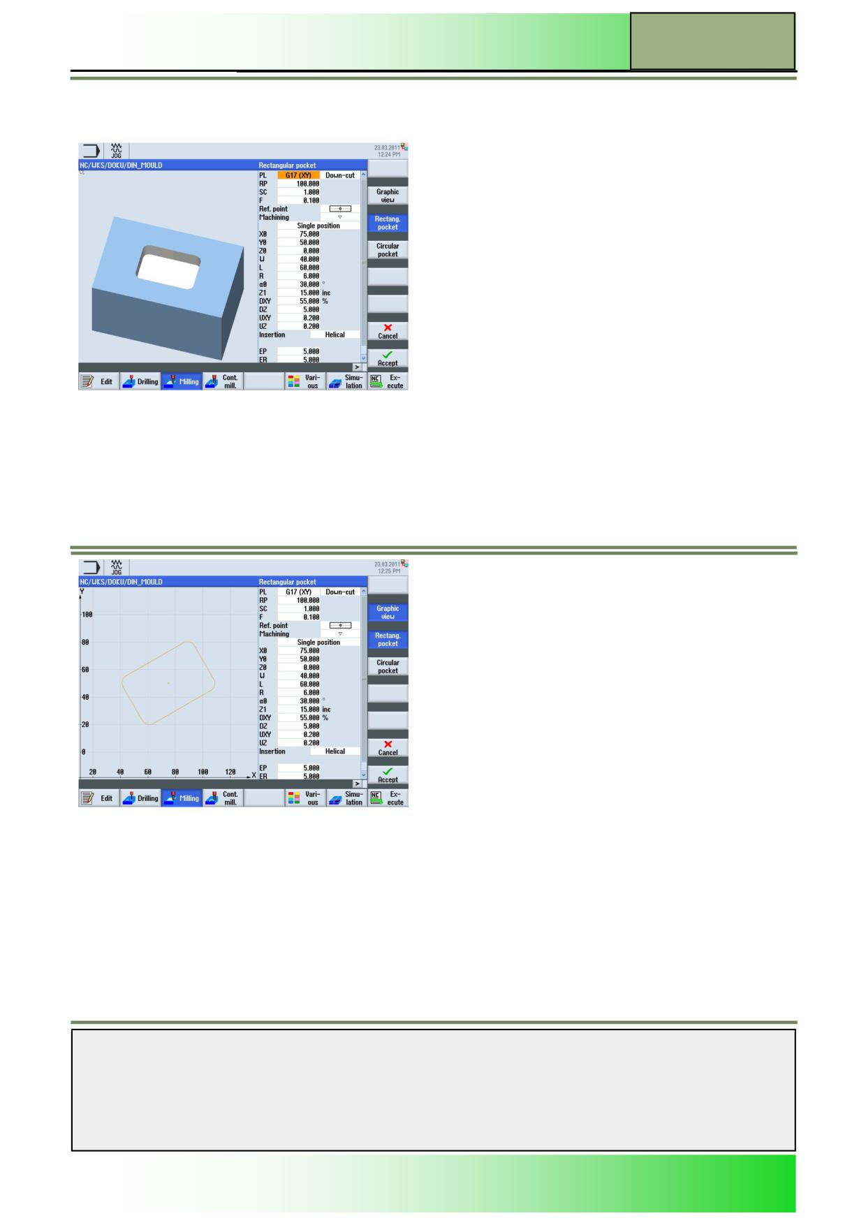
As a parameter mask, with 3-D help pictures and animation during parameter input, with the VSK 2 “Graphic view”
deactivated.
As a parameter mask with an outline drawing during parameter input, with the VSK 2 “Graphic view” activated.
Note:
The animated help pictures are displayed always in the correct position to the adjusted coordinate system.
The parameters are dynamically displayed into the graphic and are highlighted in a different colour.
Notes
828D/840Dsl SINUMERIK Operate
Page 5
M604
M604
Basics of programming with the programGUIDE
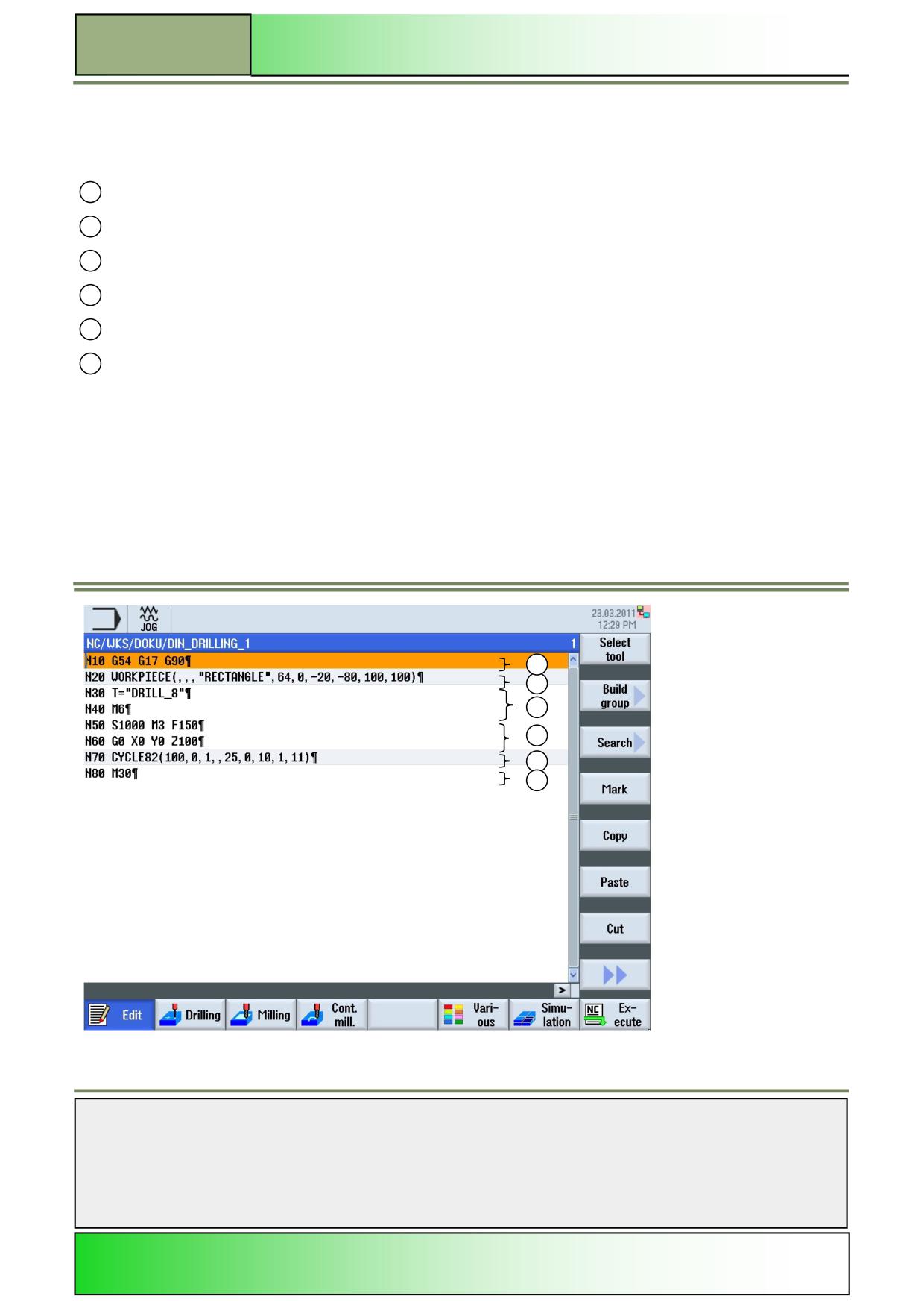
General program structure
In general, a G code program can be programmed freely.
For a good legibility however, the following structure is recommended:
1
Zero point selection, plane selection, absolute dimensioning
2
Blank attribution for the simulation
3
Tool call up and tool change
4
Technology data, path commands
5
Programming of the technologies (cycles)
5
Program end
1
2
3
4
5
6
Notes
M604
Page 6
828D/840Dsl SINUMERIK Operate

Basics of programming with the programGUIDE
M604
Standard commands in the G code Editor
Unlike in a program with ShopMill functionality, the following G-code commands are programmed through graphically sup-
ported parameter masks, where as in the programGUIDE G-code editor they have to be specifically typed into the editor.
Note: Unnamed G commands are freely selectable. The documentation by the machine manufacturer must be observed.
Command
Meaning
G 00
Rapid traverse command
G 01
Linear interpolation (Feed motion)
G 02
Circular interpolation clockwise
G 03
Circular interpolation anti-clockwise
G 04
Dwell time: additional parameters F or S are required
G 17
Plane selection XY
G 18
Plane selection ZX
G 19
Plane selection YZ
G 54 - G 57
Selection of the zero points
Note: More zero points may be available.
The documentation by the machine manufacturer must be observed.
G 90
Absolute dimensions
G 91
Incremental dimensions
The following standard M commands are available in the G code editor.
Note:
Unnamed M-commands are freely selectable.
The documentation by the machine manufacturer must be observed.
Command
Meaning
M00
Programmed Halt
M01
Optional Stop, see also M00
M02
End of Program
M03
Spindle Start clockwise
M04
Spindle Start anti-clockwise
M05
Spindle Stop
M06
Tool change
M08
Coolant ON
M09
Coolant OFF
M19
Defined spindle stop
M30
End of Program (see also M02)
Notes
828D/840Dsl SINUMERIK Operate
Page 7
M604
M604
Basics of programming with the programGUIDE
The following standard “other“ commands are available in the G code editor.
Note:
The documentation by the machine manufacturer must be observed.
Command
Meaning
T
Tool call up (Tool)
S
Speed (Speed)
F
Feed rate (Feed)
Navigation in the editor window
For a fast and comfortable navigation within a G code program and the parameter masks you can use the blue cursor
keys.
With the blue “cursor-up” key on the keyboard you can navigate upwards in the program
editor and the parameter masks.
With the blue “cursor-down” key on the keyboard you can navigate downwards in the
program editor and the parameter masks.
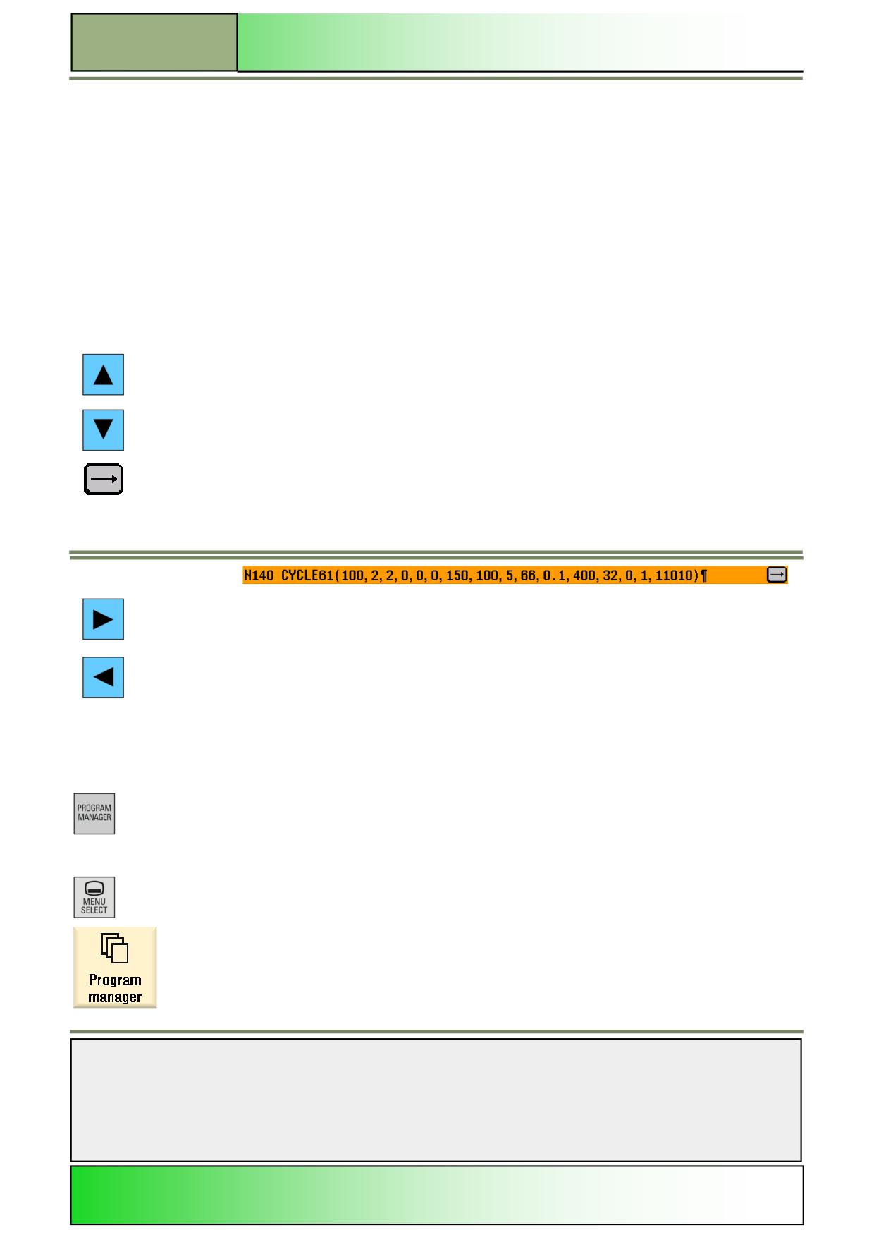
The arrow symbol (extend symbol) on the right side of a cycle or workpiece line in the editor
window indicates that you can enter the parameter input mask by pressing the “cursor-to-the-
right” key
(see picture below).
The “cursor-to-the-right”-key opens the parameter mask of the corresponding program
block.
The “cursor-to-the-left”-key closes the parameter mask for the cycle or workpiece settings
and brings you back to the editor window, displaying the G code program.
Creating G-code programs
Creating a new G code program or opening an existing one
A new G code program can be created from the operating modes “JOG”, “MDA” and “AUTO” as follows:
Press the “Program Manager“ key on the keyboard.
The program manager for creating and administering programs opens directly.
See module M575 - “Operating area Program Manager“.
- OR -
Press the “MENU SELECT“ key on the operator panel (OP).
Press the yellow HSK 1.4 “Program Manager“.
The program manager for creating new programs and administering existing programs opens.
Notes
M604
Page 8
828D/840Dsl SINUMERIK Operate
Basics of programming with the programGUIDE
M604
- THEN -
Select a storage drive (by pressing the horizontal softkey “NC”, “Local drive” or “USB”) where
you want to create the program.
Move the orange cursor with the blue cursor keys to the directory of your choice.
For the navigation process refer to the modules B566 - “Operating elements“ or
B575 - “Operating area Program Manager“.
Press the VSK 2 “New”.
The vertical softkey bar with functions for creating new programs opens.
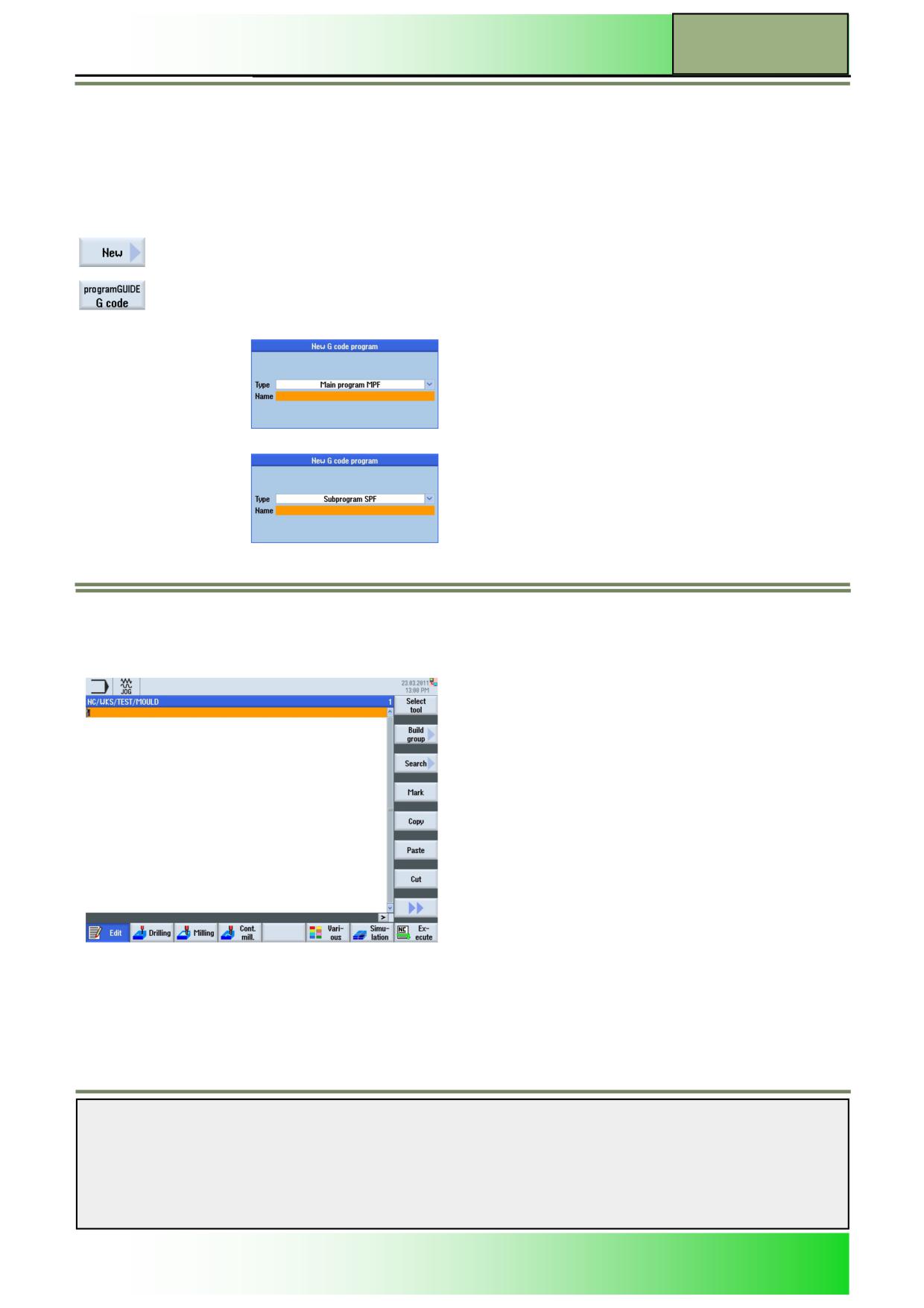
Press the VSK 3 “programGUIDE G code“, to open the input mask for creating a new ShopMill
G code program.
Here you can create a new main program
or a new subprogram.
Enter a name for the program and confirm your input by pressing the VSK 8 “OK”, or abort with
pressing the VSK 7 “Cancel”.
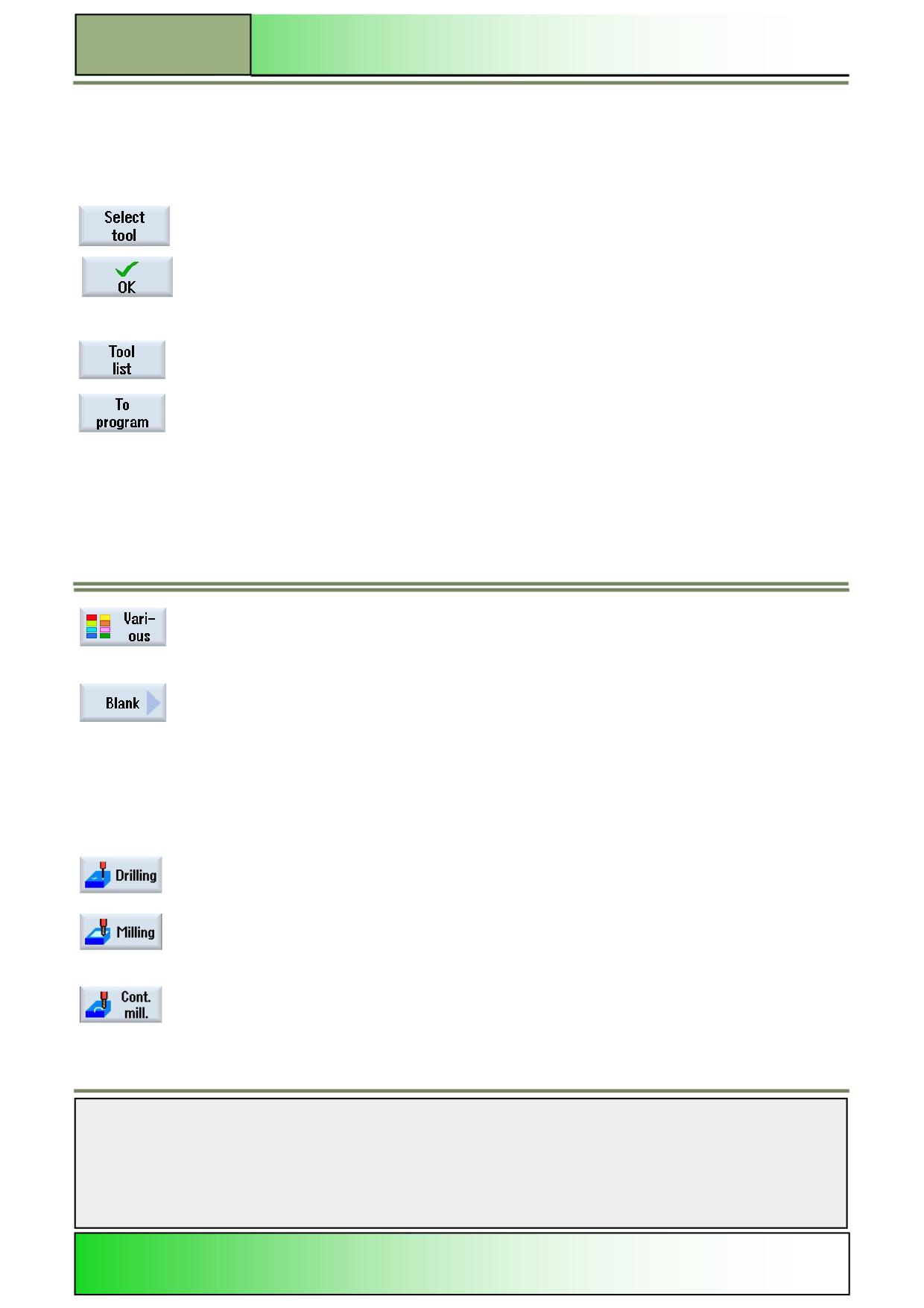
After creating a new programGUIDE program, the program is loaded into the G code editor in the operating area
“Program”, where all the functions for tool selection, entering and editing G code commands and cycles are available (see
picture below).
Notes
828D/840Dsl SINUMERIK Operate
Page 9
M604
M604
Basics of programming with the programGUIDE
Programming a tool
Within the editor, tools can be selected and inserted in the G code program comfortably by using a softkey.
Under the function “Edit” HSK 1 press the VSK 1.1 “Select Tool” to open the tool selection
window.
You can use the cursor key to select the tool you require followed by pressing the VSK 1.8
“OK”
- OR -
Press the VSK 1.2 “Tool list” Will open the tool list in the operating area “Parameter”.
(see module - M573 “Operating area Parameter”).
Select an already existing tool from the tool list by placing the orange selection cursor on that
tool and pressing the VSK 1.1 “To program”.
Afterwards program the tool change (M06), the spindle start (M03/M04), the coolant (M07/
M08), the speed (S...), the feed (F) and if needed, some tool specific functions.
Programming the blank
The blank is needed for the simulation and the simultaneous recording.
Only with a blank, that represents the real blank as precise as possible, a accurate simulation is possible. For the blank you
have to define the shape (Block, Pipe, Cylinder, N corner or Block centric) and dimensions.
In the operating area “Program” press the HSK 1.6 “Various” to open the vertical softkey bar
with “various” functions.
Here, press the VSK 1.1 “Blank” to open the input mask for defining the blank.
Fill in the needed parameters and press the VSK 8 “Accept” to take over the blank settings into
the program, or abort by pressing the VSK 7 “Cancel”.
Programming a cycle
Cycles (technologies) can be programmed easily by using softkeys and parameter masks as follow.
In the operating area “Program”
press the HSK 1.2 “Drilling”, or
press the HSK 1.3 “Milling”, or
press the HSK 1.4 “Cont. mill.”,
to open the cycles for drilling, milling or contour milling. Select the corresponding technology
(cycle) and a position pattern and accept the input.
See module M609 - “Drilling“, M616 - “Milling” and M624 - “Contour milling“.
Notes
M604
Page 10
828D/840Dsl SINUMERIK Operate
Basics of programming with the programGUIDE
M604
Inserting G code and programming the program end
In the G code editor window several functions for inserting, copying and cutting G code commands are available.
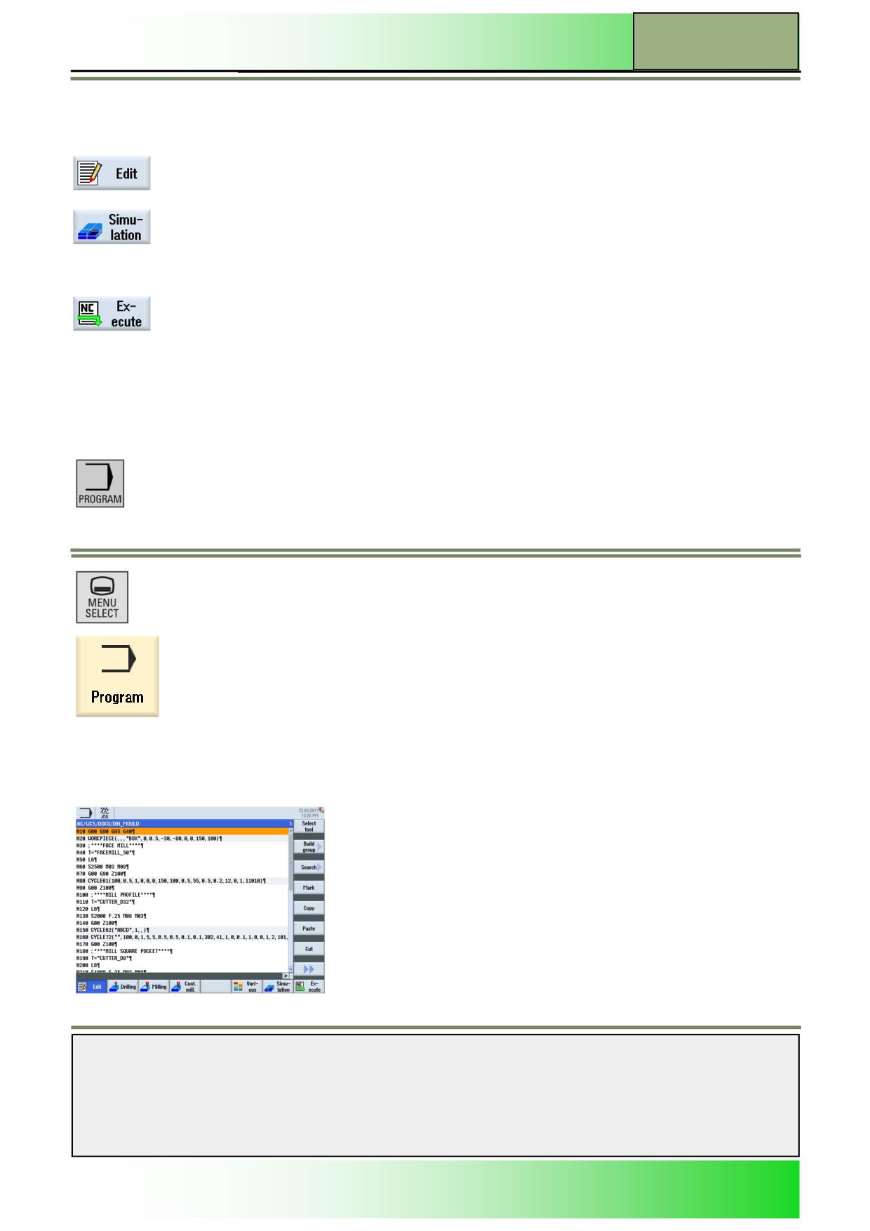
In the operating area “Program” press the HSK 1 “Edit” to program a part program with G code
commands or to edit an already loaded program.
Then program the program end (M02/M30).
Press the HSK 1.7 “Simulation“ to simulate the machining.
- OR -
Press the HSK 1.8 “NC Execute” to load the program to the NC memory, ready for machining.
With the editor you can create, supplement, or change part programs.
Editor
Selecting the function “Edit”
The program editor can be opened from the operating modes “JOG”, “MDA” or “AUTO”.
By pressing the “PROGRAM“-key on the keyboard the editor window opens directly, with the
last opened program.
If no program was loaded before, the program manager window opens instead, where you can
create or select an existing program.
- OR -
Press the “MENU SELECT“-key on the operator panel.
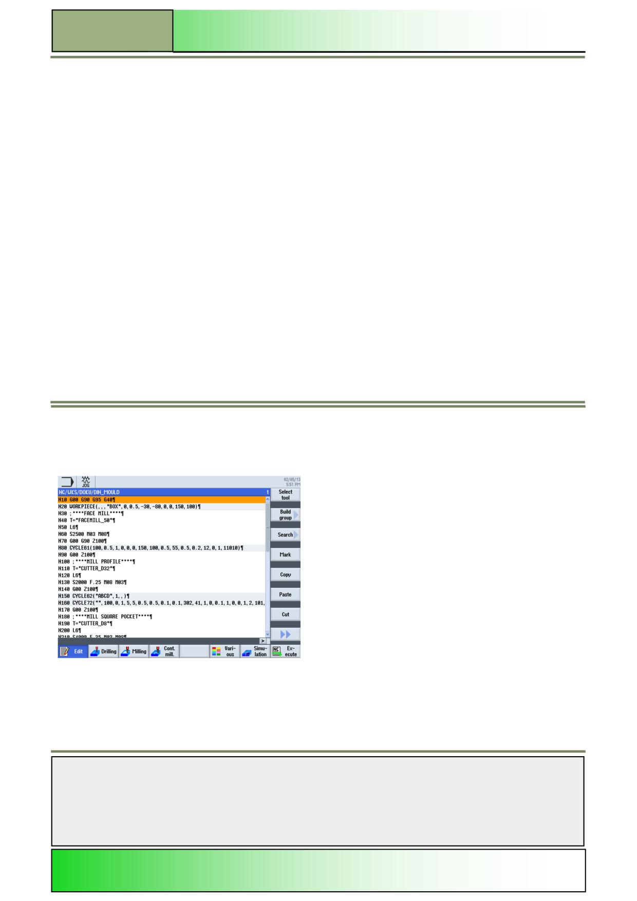
Press the yellow HSK 3 “Program” to open the operating area “Program”. By default the editor
window opens with the last opened program (see picture below).
Note:
If the function is not active, press the HSK 1 “Edit“.
If no program had been opened for editing purpose, then the Sinumerik Operate opens the
Program Manager window, offering a chance to the user for choosing the desired program for
editing.
For further details see module - M575 “Operating area Program Manager”.
The following softkeys are available for editing a program:
Notes
828D/840Dsl SINUMERIK Operate
Page 11
M604
M604
Basics of programming with the programGUIDE
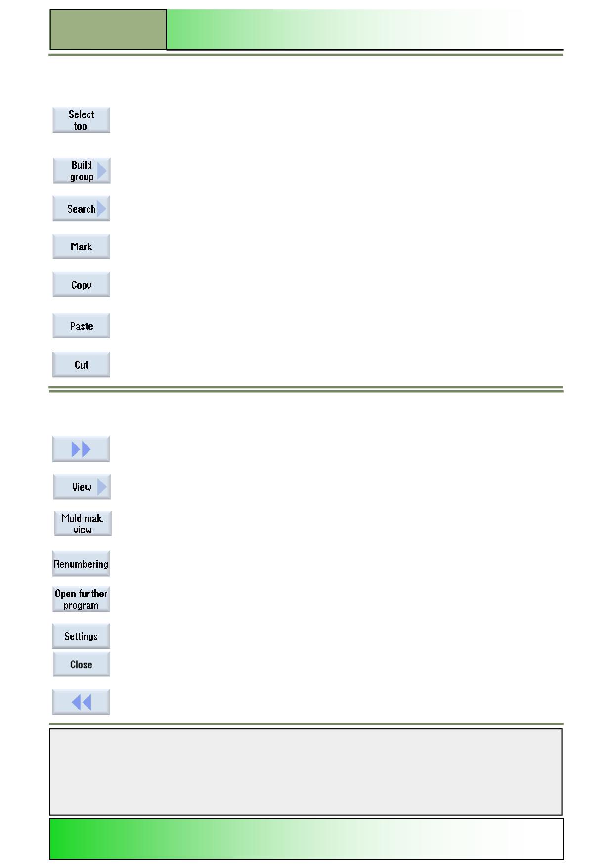
Vertical softkey bar 1 and 2
Display area
Description
Under the function “Edit” HSK 1 press the VSK 1.1 “Select Tool” to open the tool selection win-
dow.
Here you can select a tool, By pressing the VSK 1.8 “OK” you can insert the selected tool data
into the G code program.
By pressing the VSK 1.2 “Build group” you can create programme blocks into groups, this can
be useful when creating large programs.
By pressing the VSK 1.3 “Search“ you can search for any text in the current program. A search
window opens where you can enter a search string. You can continue searching afterwards.
By pressing the VSK 1.4 “Mark” you can mark one or several program blocks in order to copy or
cut (delete) them.
By pressing the VSK 1.5 “Copy” you can copy one or several program blocks to the internal
memory of the control, to paste them to a different location in the active program or to another
program.
By pressing the VSK 1.6 “Paste“ copied or cut program blocks can be inserted behind the se-
lected program block (actual cursor position). You can paste the block to the active program as
well as to another G code program on the NC, local drive or USB.
By pressing the VSK 1.7 “Cut” you can cut out one or several program blocks, to paste them
later somewhere in a program or to delete them. Cut program steps remain in the clipboard and
can be inserted again with the VSK 1.6 “Paste”.
Vertical softkey bar 1 and 2 continued
Display area
Description
By pressing the VSK 1.8 “Extend“ the extended vertical softkey bar 2 will be displayed.
By pressing the VSK 2.1 “View” you can choose between “Close all blocks” and “Open all
blocks”.
By pressing the VSK 2.2 “Mold mak. view” you can see the simulated workpiece from a top
view as an outline drawing.
By pressing the VSK 2.3 “Renumbering” you can assign new numbers for every program step
in the editor window.
By pressing the VSK 2.4 “Open further program” you can view two programs side by side.
By pressing the VSK 2.6 “Settings“ you can change the setting for the program editor .
By pressing the VSK 2.7 “Close” you close the editor with the active program.
By pressing the VSK 2.8 “Back“ you switch back to the vertical softkey bar 1.
Notes
M604
Page 12
828D/840Dsl SINUMERIK Operate
Basics of programming with the programGUIDE
M604
Select tool
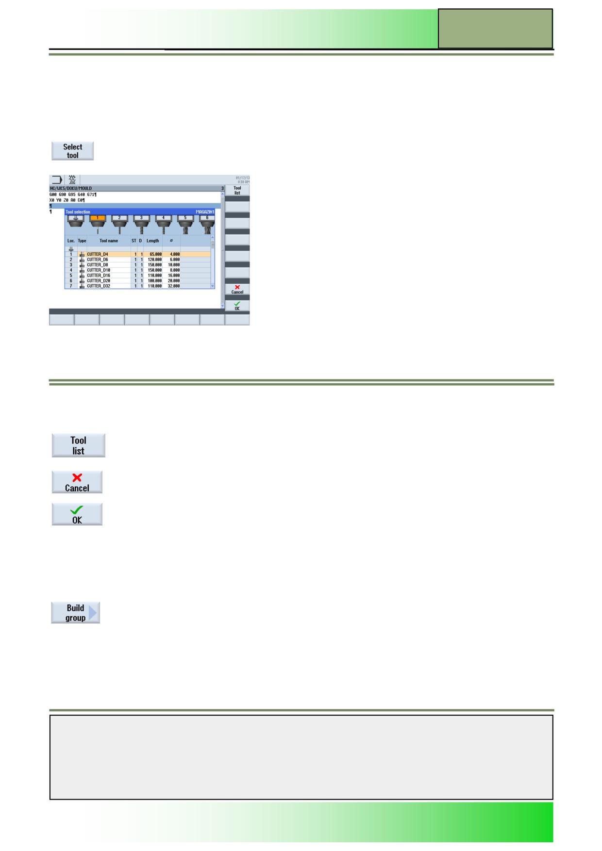
With the function “Select tool” you can search and select a tool .
Selecting the function “Select tool”
By pressing the VSK1.3 “Select tool” the search window opens like displayed below, with the
following functions available in the vertical softkey bar.
Use the “cursor up & cursor down” keys on the key board the select the required tool for the machining block.
If the required tool is not available press the VSK1 “Tool list” so that a new tool can be created .
Vertical softkey bar
Display area
Description
By pressing the VSK 1 “Tool list” you are taken to the tool list.
See module - M573 “Operating area Parameter”.
With pressing the VSK 7 “Cancel” you can abort the search process.
By pressing the VSK 8 “OK“ you will load the selected tool into the machining block.
Build group
With the function “Build group” you can group similar machining blocks together .
Selecting the function “Search”
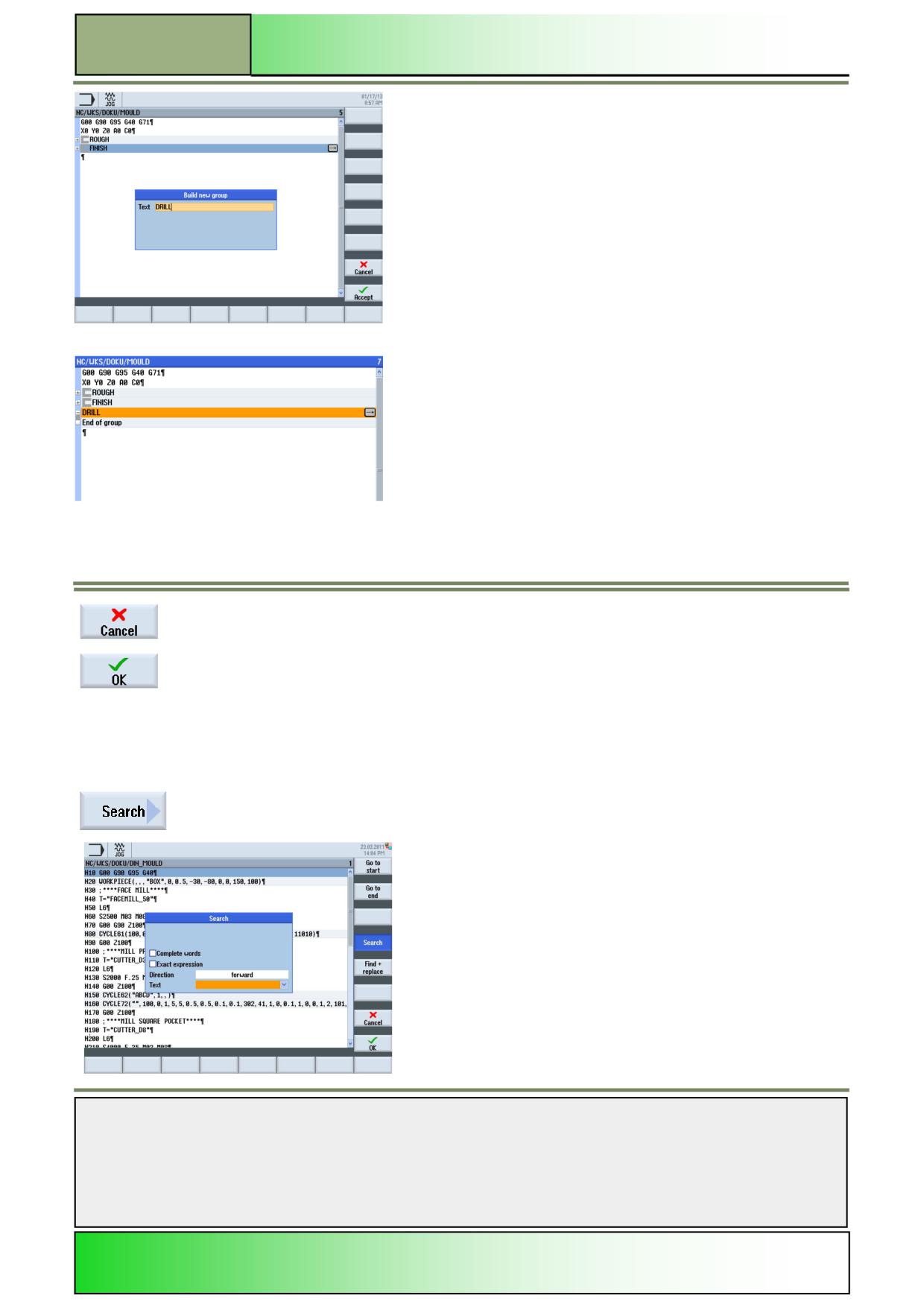
By pressing the VSK1.2 “Build group” the build new block window opens like displayed below,
allowing you to give a name to a group
Notes
828D/840Dsl SINUMERIK Operate
Page 13
M604
M604
Basics of programming with the programGUIDE
Once you have typed in a name press the “OK” softkey
You can now create machining blocks inside the group.
Vertical softkey bar
Display area
Description
With pressing the VSK 7 “Cancel” you can abort the search process.
By pressing the VSK 8 “OK“ you will load a new group block into the program with the name
you have chosen.
Search
With the function “Search” you can search for any text in a sequential program and even replace the text with other text.
Selecting the function “Search“
By pressing the VSK1.3 “Search” the search window opens, where you can search for any
program code in the current program.
Notes
M604
Page 14
828D/840Dsl SINUMERIK Operate
Basics of programming with the programGUIDE
M604
Vertical softkey bar
Display area
Description
By pressing the VSK 1 “Go to start” the cursor will be positioned on the first line of the program.
By pressing the VSK 2 “Go to end” the cursor will be positioned on the last line of the program.
By pressing the VSK4 “Search” the search mask opens, where you can decide to search for
complete words, select the search direction (forward/backwards) and enter the search text.
By pressing the VSK5 “Find + replace” the “Search and replace” mask opens where you can
decide to search for complete words, select the search direction (forward/backwards), enter the
search text and enter the text you want to use for the replacement.
With pressing the VSK 7 “Cancel” you can abort the search process.
By pressing the VSK 8 “OK“ you start a search run with the above mentioned search criteria.
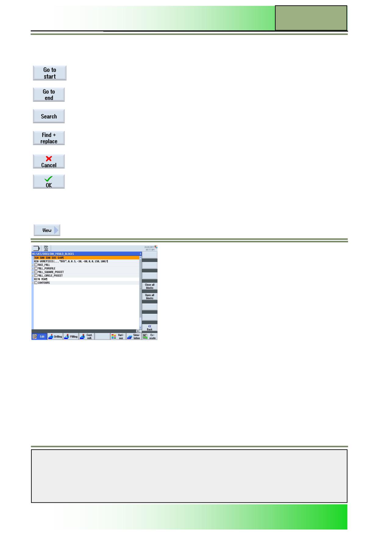
View
With the function “View” you can expand or close all “groups” that have been created in the program.
Selecting the function “View”
By pressing the VSK2.1 “View” the softkeys “Close all blocks” and “Open all blocks” are shown
like displayed below.
Press VSK 5 “Open all blocks”
Notes
828D/840Dsl SINUMERIK Operate
Page 15
M604
M604
Basics of programming with the programGUIDE
Vertical softkey bar
Display area
Description
Pressing the VSK 4 “Close blocks” you can close all block in the program.
Pressing the VSK 5 “Open blocks“ you can open all block in the program
With the VSK 8 “Back” you can go back to the previous vertical softkey bar.
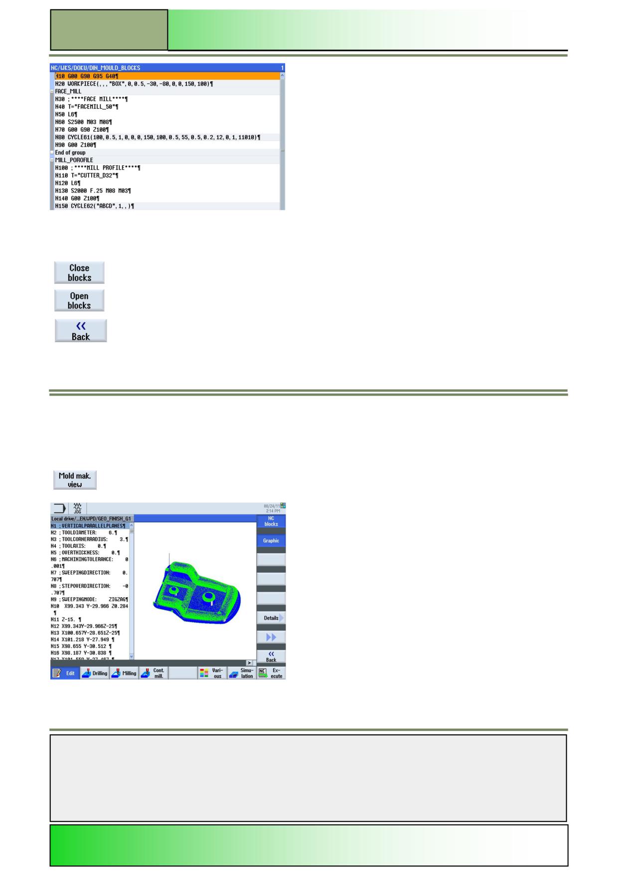
Mold mak. view
With the function “Mold mak. view” you can open up the quick viewer, this allows you to see a simulated picture of the mold
program.
Selecting the function “Mold mak. view”
By pressing the VSK2.2 “Mold mak. view” the softkeys “Close all blocks” and “Open all blocks”
are shown like displayed below.
Notes
M604
Page 16
828D/840Dsl SINUMERIK Operate
Basics of programming with the programGUIDE
M604
Vertical softkey bar
Display area
Description
Pressing the VSK 1 “NC blocks” the window for the NC blocks is opened or closed.
Pressing the VSK 2 “Graphic“ the window for the graphics is opened or closed.
With the VSK 6 “Details” the following functions can be used:
Autozoom
Zoom +
Zoom -
Zoom
Pressing the VSK 7 followed by VSK2.3 “Select point“ a point on the graphics can be selected
and the corresponding NC line will be shown, or visverser.
Pressing the VSK 8 “Back” the Mold mak. View window closed.
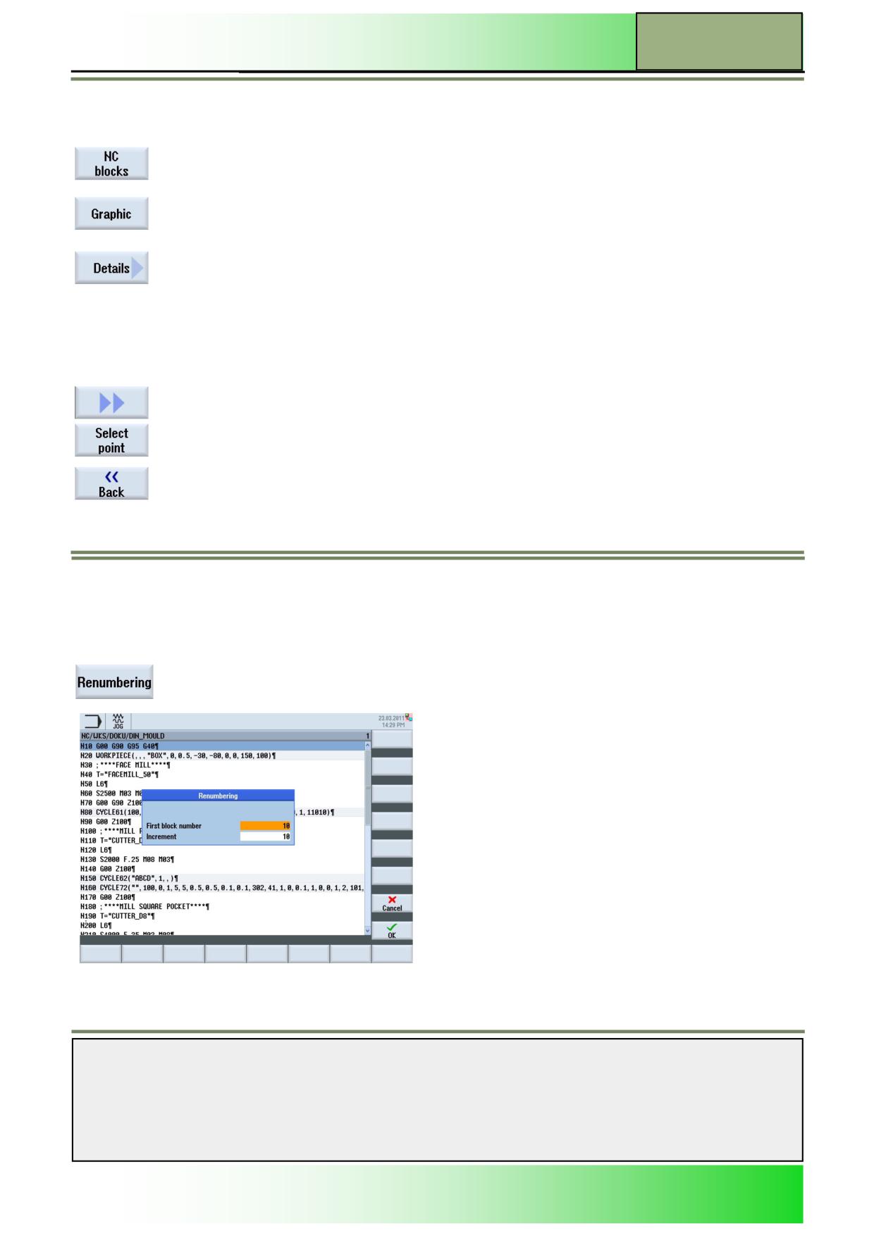
Renumbering
With the function “Renumbering” you can renumber manually the program steps in the work plan with an increment you
can select here.
Selecting the function “Renumbering“
By pressing the VSK 2.3 “Renumbering” the input window opens where you can change the
settings for the renumbering of the program blocks in the editor window.
Notes
828D/840Dsl SINUMERIK Operate
Page 17
M604
M604
Basics of programming with the programGUIDE
Parameters for “Renumbering”
Parameters
Meaning
First block number
The first block number you want to start with.
The values shown here by default can be adjusted under the function “Settings” in the input
field “First block number”.
Increment
The Increment between the program blocks.
The values shown here by default can be adjusted under the function “Settings” in the input
field “Increment”.
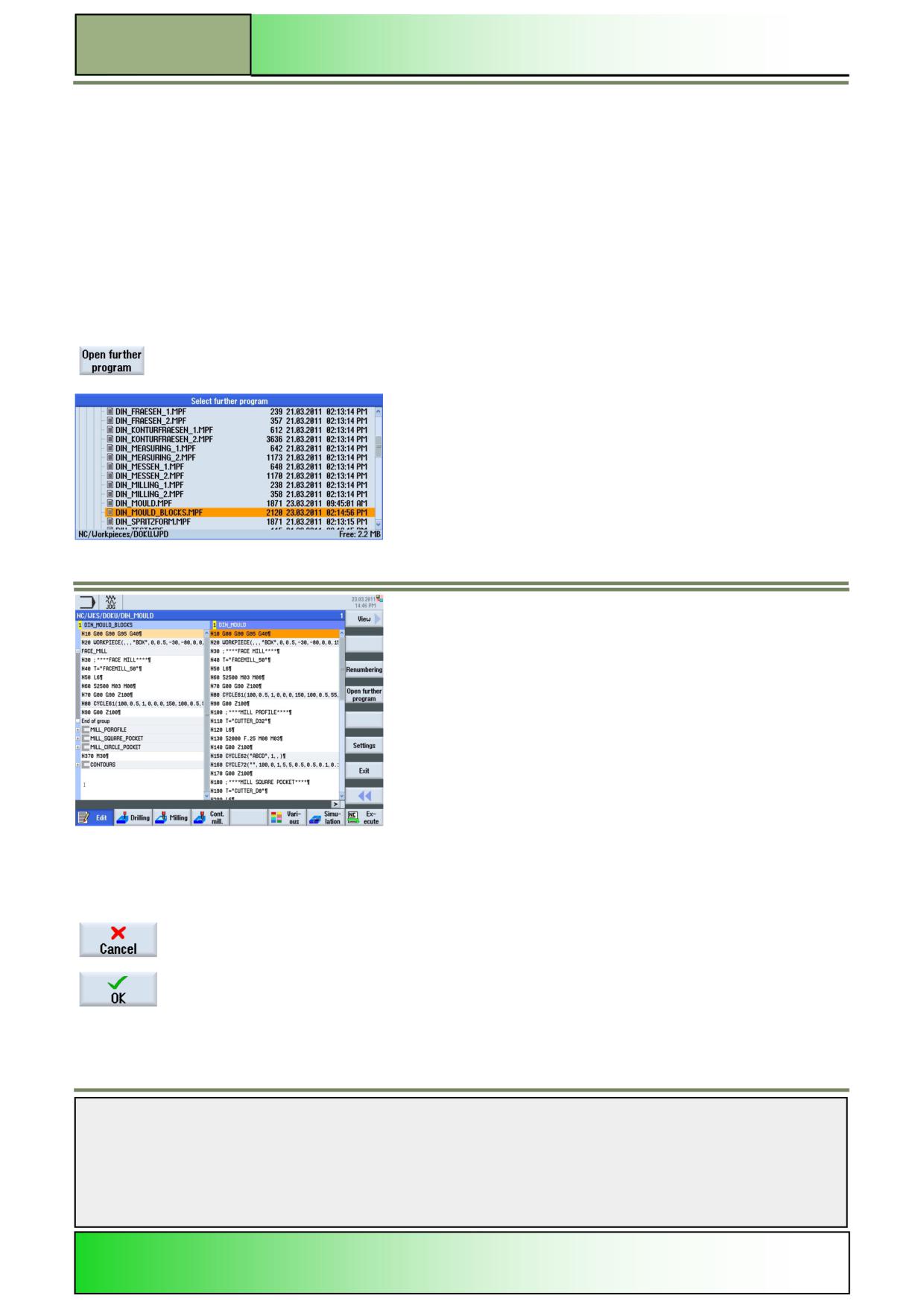
Open further programs
With the function “Open further programs” the control will show two programs side by side.
Selecting the function “Open further programs”
By pressing the VSK2.4 “Open further programs” the window opens that allows you to choose a
further program to be shown.
Use the “cursor up” or “cursor down” keys on the key board the select the required program and press VSK8 “OK”
Vertical softkey bar
Display area
Description
With pressing the VSK 7 “Cancel” you can abort the select process.
By pressing the VSK 8 “OK“ the control will show two programs side by side, as shown above.
Notes
M604
Page 18
828D/840Dsl SINUMERIK Operate
Basics of programming with the programGUIDE
M604
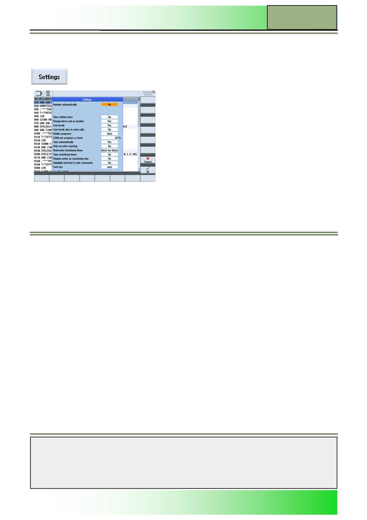
Settings
With the function “Settings” you can change the settings for the program editor.
Selecting the function „Settings“
By pressing the VSK 2.6 “Settings” the settings window for the program editor opens.
Parameters for “Settings”
Parameters
Meaning
Number automatically
Program blocks will be numbered automatically.
(Yes/No)
Deactivating this parameter, hides the following two parameters too.
Show hidden lines
Show hidden line (with the ID ;*HD).
(Yes/No)
Display block end as
A symbol is displayed at the end of each block.
symbol (Yes/No)
Line break (Yes/No)
Lines are broken and wrapped around, or a horizontal scrollbar is displayed
Line break also in cycle If the line of a cycle call becomes too long, then it is displayed over several lines, or the line is
call (Yes/No)
truncated.
Visible programs
Selects how many programs can be displayed next to one another in the editor
Width of program w. fo-
Here, you enter the width of the selected program in the editor as a percentage of the window
cus
width.
Save automatically
Changes are saved automatically without a query.
(Yes/No)
Only cut after making
The cutting of program sections is possible only when program lines have been selected or
(yes/no)
where the cursor is positioned.
determine machining
Block-by-block / off / Non-modal
times
Display cycles as ma-
The cycle calls in the G code are displayed as plain text or NC syntax.
chining step (Yes/No)
Highlight selected G
Selected G code commands or key words can be highlighted in colour
code commands
Font size
Defines the font size for the editor and the display of the program sequence
Notes
828D/840Dsl SINUMERIK Operate
Page 19
M604
M604
Basics of programming with the programGUIDE
Various
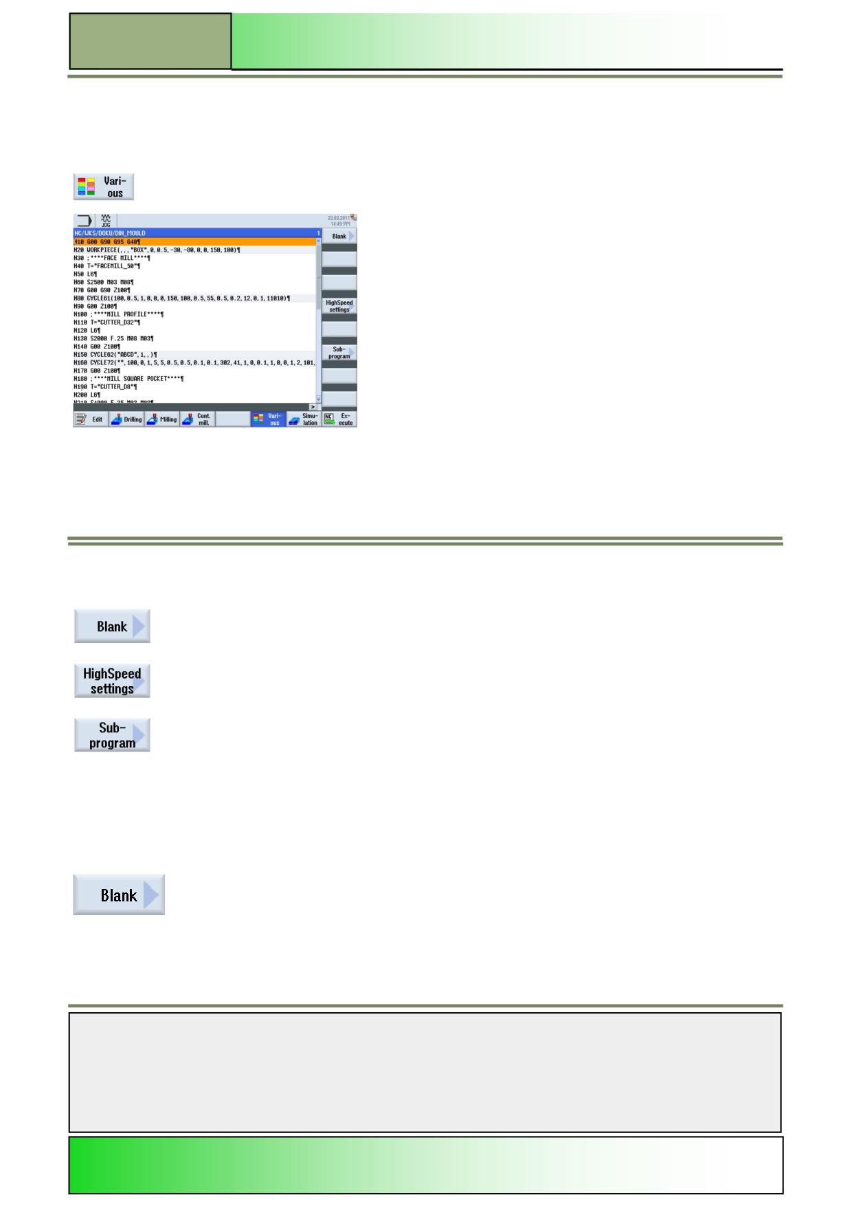
Selecting the function “Various”
The function “Various” can be selected from the operating mode “JOG”, “MDA” or “AUTO” in the operating area “Program”
as follows:
Press the HSK 6 “Various“ to switch over to the function “Various”.
Following functions are displayed in the vertical Softkey bar in the program editor.
Vertical softkey bar 1 and 2
Display area
Description
By pressing the VSK 1.1 “Blank“ an input mask opens where you can change the settings for the
blank (see section “Blank”).
By pressing the VSK 1.4 “HighSpeed settings“ the input mask for adjusting the settings for the
optimal speed in relation to the machining method opens.
By pressing the VSK 1.6 “Subprogram” the input mask for calling a subprogram opens in the
main program.
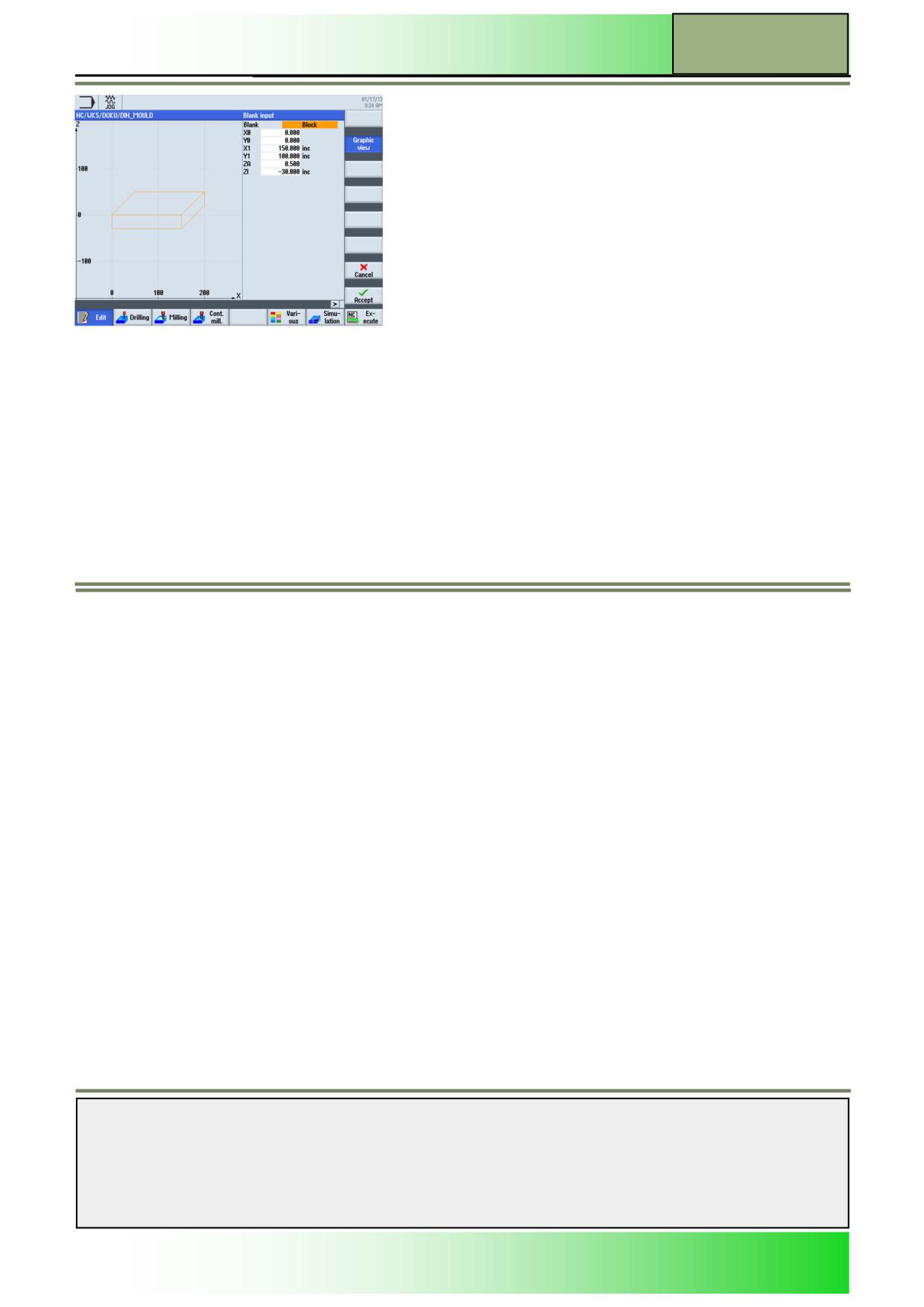
Blank
The blank is needed for the simulation and the simultaneous recording during machining. Only with a blank, which corre-
sponds to the real workpiece as exactly as possible, a meaningful simulation is possible.
For defining the blank, the form (block, pipe, cylinder, N corner, block centred) and the dimensions are needed.
Selecting the function “Blank“
By pressing the VSK 1.1 “Blank” the blank input window opens.
Notes
M604
Page 20
828D/840Dsl SINUMERIK Operate
Basics of programming with the programGUIDE
M604
Parameters for the “Blank”
Parameter
Meaning
Blank
The following blank can be selected:
Block centred
Block
Pipe
Cylinder
N-corner
X0
1 corner point X
Y0
1 corner point Y
X1 (abs/ink)
2 corner point related to X0 (absolute or incremental)
(only with block)
Y1 (abs/ink)
2 corner point related to Y0 (absolute or incremental)
(only with block)
ZA
Initial dimension
ZI (abs/ink)
Final dimension related to ZA (absolute or incremental)
XA
Outside diameter (only with pipe or cylinder)
XI
Inside diameter (absolute or incremental)
N
Number of edges (only with N corner)
SW
Width across flats (only with N corner)
W
Width of blank (only with Block centred)
L
Length of blank (only with Block centred))
Notes
828D/840Dsl SINUMERIK Operate
Page 21
M604
M604
Basics of programming with the programGUIDE
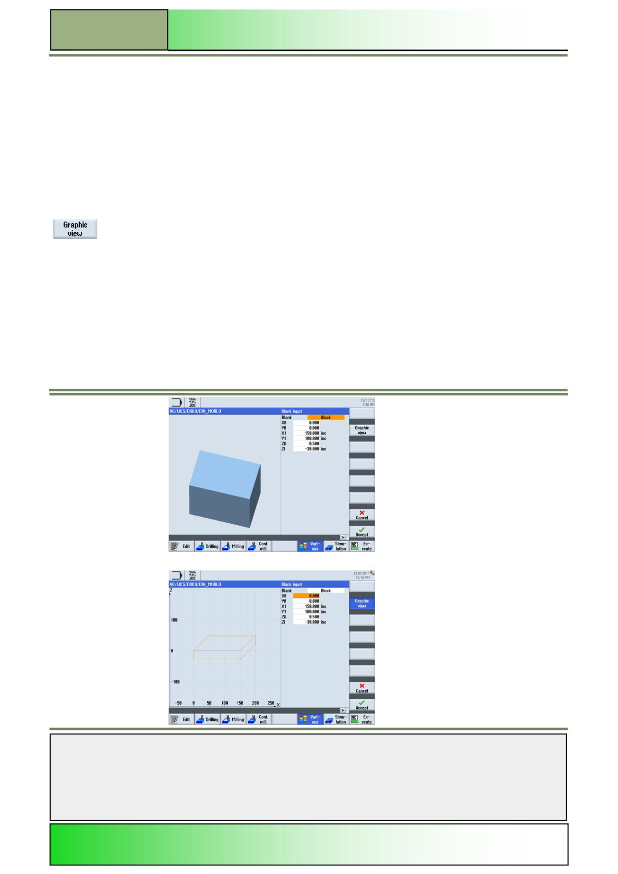
Changing the graphical view on the blank
The graphic view on the blank is adjustable in the operation area “Program” under the functions “Edit”, Drilling”, “Milling”,
“Contour milling”, “Various” and “Straight Circle” by pressing the VSK 1.2 “Graphic view”. Within the function “Various”
you can adjust the graphic settings with the Softkey “Graphic view” for the blank.
Help pictures and animations are only displayed if the VSK 2 “Graphic view” is deselected and then only in the side view.
You can change the graphic view on the blank as follows:
1.
In the operating area “Program” and operation mode “JOG”, “MDA”, or “AUTO” press the HSK
1.6 “Various”.
2.
Press the VSK 1.1 “Blank” to open the input mask for the blank settings.
By activating and deactivating the VSK 2 “Graphic view” you can switch the graphical repre-
sentation of the blank, the help pictures and animations between 2 different views:
3D view/side view
Notes
M604
Page 22
828D/840Dsl SINUMERIK Operate
Basics of programming with the programGUIDE
M604
Changing the setting for the blank
1.
In the operating area “Program” and operation mode “JOG”, “MDA”, or “AUTO” press the HSK
1.6 “Various”.
2.
Press the VSK 1 “Settings”.
3.
Optionally change the graphic view for the blank between 3D-/side view or wireframe model by
pressing the VSK 2 “Graphic view”.
4.
Enter the parameter values for the blank.
5.
Confirm your inputs by pressing the VSK 8 “Accept” or abort with pressing the VSK 7 “Cancel”.
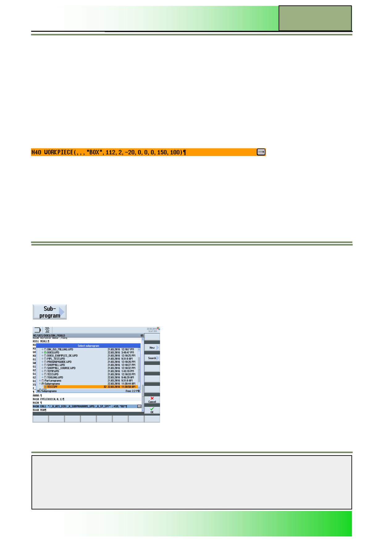
A new program block “Workpiece” is inserted in the program (see the picture below).
Subprogram
If you require the same machining steps in the programming of different workpieces, you can define these machining steps
in a separate routine. You can then call this subroutine in any programs.
Identical machining steps therefore only have to be programmed once. ShopMill does not differentiate between main pro-
gram and subprogram. This means that you can call a "standard" sequential control or G code program as subprogram in
another sequential control program. In this subprogram, you can also call another subprogram. The maximum nesting
depth is 8 subroutines. You cannot insert subroutines among blocks chained by the control. If you want to call a sequential
control program as a subroutine, the program must already have been calculated once (load or simulate
program in “Machine Auto” mode). This is not necessary for G code subroutines. The subroutine must always be stored in
the NCK main memory (in a separate directory "XYZ" or in the "ShopMill", "Part programs", "Subroutines" directories). If
you want to call a subprogram located on another drive, you can use the G code command "EXTCALL".
Note:
Please note that, when a subprogram is called, ShopMill evaluates the settings in the program header of the subroutine.
These settings also remain active even after the subprogram has ended. If you wish to activate the settings from the pro-
gram header for the main program again, you can make the settings again in the main program after calling the subpro-
gram.
Selecting the function “Subprogram”
By pressing the VSK 3 “Subprogram”, the input window for calling up a subprogram opens.
Notes
828D/840Dsl SINUMERIK Operate
Page 23
M604

M604
Basics of programming with the programGUIDE
Loading subprograms
1.
In the operating area “Program“ and operating mode „JOG“, „MDA“ or „AUTO“ press the HSK 6
“Various“.
2.
Press the VSK 1.6 ”Subprogram”.
3.
Enter the directory path to the subprogram and the name of the subprogram in the input mask.
4.
Press the VSK 8 “Accept” to confirm your inputs or press the VSK 7 “Cancel” to abort.
A new program block “Execute” with the directory path to the subprogram is inserted
(see picture below):
M604: END
Notes
M604
Page 24
828D/840Dsl SINUMERIK Operate
M559
Loops, jumps, repetitions
Sinumerik
Operate
Module Description:
In the module you will learn about the commands for looping parts of the program, for jumping to cer-
tain blocks in the program and how to repeat certain sections of the program.
Module Objective:
Working through this module you become familiar with the usage of loops, jumps and
repetitions in a milling program.
Content:
Label name, Parameter usage
Jump instructions, Program section repetitions
Summary
This document was produced for training purposes.
828D/840Dsl SINUMERIK Operate v4.7
Page 1
M559
Siemens assumes no responsibility for its contents.
M559
M559
Page 2
828D/840Dsl SINUMERIK Operate

Loops, jumps, repetitions
M559
Loops, jumps,
repetitions:
START
Label name,
Parameter
usage
Jump
instructions,
Program
section
Summary
Loops, jumps,
repetitions:
END
Notes
828D/840Dsl SINUMERIK Operate
Page 3
M559

M559
Loops, jumps, repetitions
Label name, Parameter usage
Label name
In order to repeat certain sections of a program or the jump to a certain section of the program, we make use of “LABELS”
to mark the beginning/end of certain sections of the program. In most cases a “LABEL” is used to mark the beginning, but
when you want to perform repetitions of sections of a program, then you require both beginning and end “LABELS” (refer to
section 3.2 in this module).
The “LABEL” must consist of at least two or a maximum of 8 characters. The first two characters must always be letters or
underlines.
The “LABEL” must always be followed by a colon.
N100...
Assigning the name START1: to a label
N110 START1:
N120 G00 X10..
Parameter usage
In some cases the use of parameters is highly advisable. For instance, the cutting values for the tools to be used can be
assigned to parameters in the program header, which can then be used for programming instead of the cutting values them-
selves. The parameters are programmed with the address letter “R” and a number “R1”. Values can be assigned to these in
the section “Parameter” or also in the program itself.
;T1-WSF Dr60
Program header
R1=200 ;
n for WSF Dr60
R2=30 ;
vf for WSF Dr60
N100 T1 ; WSF Dr60
N110 M6
Assignment of speed and feed by means of
N120 S=R1 F=R2 M3 M8 D1
R1 and R2
N130 ...
Parameters can be used within the program for calculation of individual values or for themselves. For reason of the advance
calculation by the control unit it is possible that undesirable effects on the active parameters might occur. This can be pre-
vented by using the instruction STOPRE.
The next block will only be executed after the previous block has been finished.
For this “STOPRE” must be written in a block by itself.
N10 R1=0
N110 START1:
N120 G00 x10..
…
N140 STOPRE
The control unit waits until block N130 has been
N150 R1=R1+1
completed.
N160 END1:STOPRE
Each time the block is run for machining R1 is in-
creased by 1.
Jump instructions, Program section repetitions
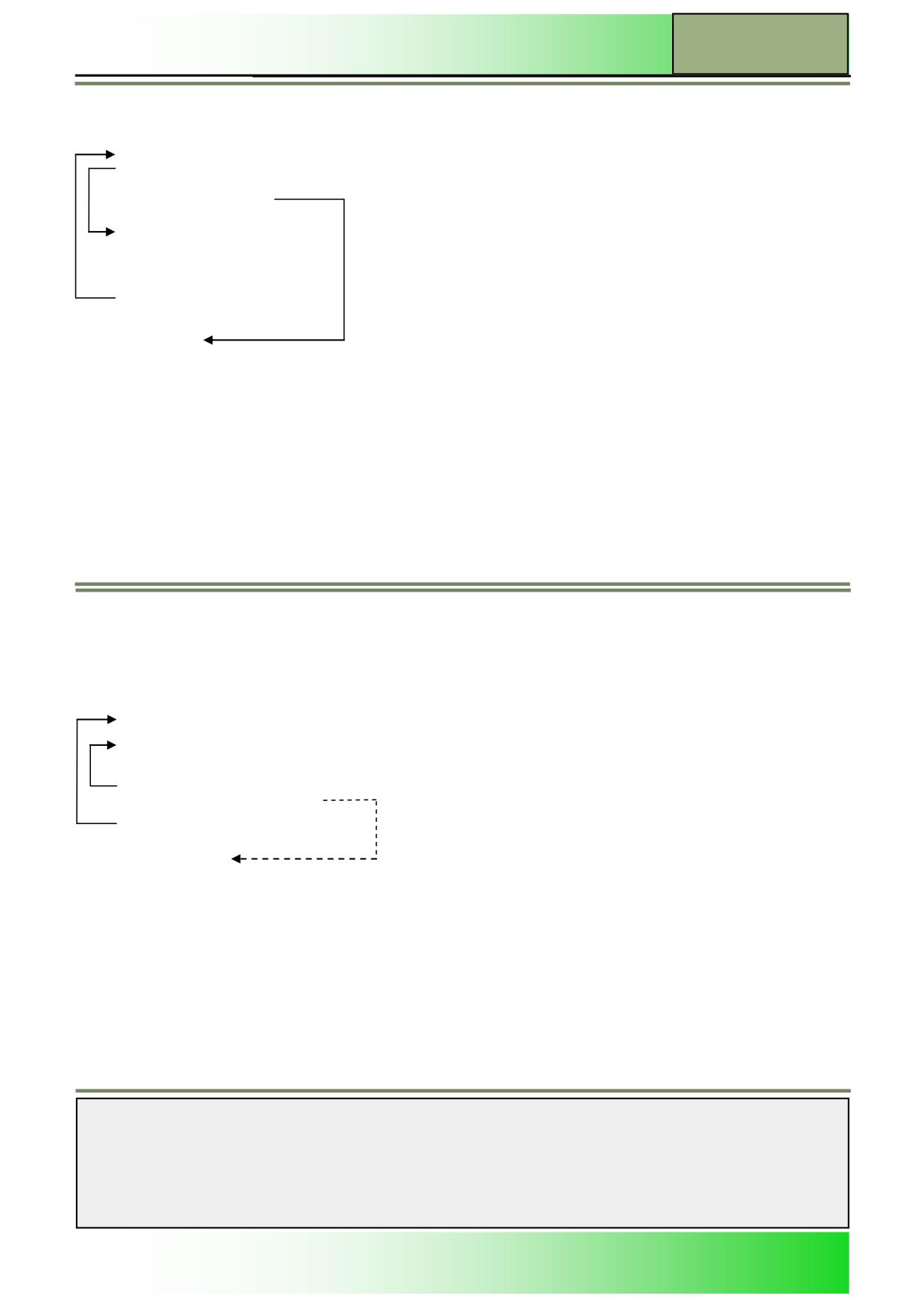
Jump instructions
Jump instructions can also be used within a program. They permit the omission of certain sections of the program or to
jump back for repetitions. The instruction GOTOF is used to jump forward, while the GOTOB is used to jump backward.
For this a search is carried out for the included label name or the block number before the jump to this location is carried
out.
Notes
M559
Page 4
828D/840Dsl SINUMERIK Operate
Loops, jumps, repetitions
M559
;T1-WSF Dr60
R1=200 ;
n for WSF Dr60
R2=30 ;
vf for WSF Dr60
N10 GOTOF N100
N20 LB001:
Jump to block N100
…
N90 GOTOF N170
N100 T1 ; WSF Dr60
Jump to block N170
N110 m6
N120 S=R1 F=R2 M3 M8 D1
N130 …
N160 GOTOB LB001
N170 T4
Jump back to label LB001
The jump instruction caused a change in the machining sequence.
Program section repetitions
Program sections between two labels can be repeated any number of times as specified under the address P. For this the
program jumps to the first stated label and executes all blocks of the program until the second label is reached. If the num-
ber of repetitions is greater than one, this procedure will be repeated as often as stated under address “P”.
;T1-WSF Dr60
R1=200 ;
n for WSF Dr60
R2=30 ;
vf for WSF Dr60
N10 T1 ; WSF Dr60
N20 M6
N30 S=R1 F=R2 M3 M8 D1
N40 G00 z2
1
N50 LB001:
2
N50 G1 Z=IC(-10)
…
N90 LE001:
N160 Repeat LB001 LE001 P2
N170 T4
Jump back to Label LB001 and two
repetitions between LB001and
LE001
Notes
828D/840Dsl SINUMERIK Operate
Page 5
M559

M559
Loops, jumps, repetitions
Summary
Loops/ jumps/repetitions
Instruction
Meaning
GOTOF
Forward jump to destination mark
GOTOF LB001 or GOTOF N110
GOTOB
Backward jump to destination mark
GOTOB LB002 or GOTOB N10
Note:
When using “GOTOB” and “GOTOF” care must be
taken against endless loops. They call up each other repeatedly. Hence the program cannot
leave this range.
The use of block numbers as destination mark is not advisable. If the block number changes,
there will be no automatic correction.
REPEAT
Repeats the section between the labels for the programmed number of times.
Repeat LB002 LE002 P2
Note:
The use of block numbers as destination mark is not advisable. if the block number changes,
there will be no automatic correction.
R...
Parameter 1-99
R1
STOPRE
The next block will not be decoded until the previous block has been completed.
….:
Label name
LB001:
Note:
Label names must have at least 2 and a
maximum of 8 characters. The first 2 of which
must be either letters or underlines.
G04
Dwell
G04 S2 Dwell for 2 revolutions
G04 F2 Dwell for 2 seconds
M559: END
Notes
M559
Page 6
828D/840Dsl SINUMERIK Operate
M616
Milling with programGUIDE
Sinumerik
Operate
Module Description:
This module explains the explains the programming of a simple milling example with the program-
GUIDE in ShopMill, by means of milling cycles and a position pattern.
Module Objective:
Working through this module you learn about the technology “Milling” by programming a
G code programs with the programGUIDE in ShopMill.
Content:
Simple programming example
This document was produced for training purposes.
828D/840Dsl SINUMERIK Operate v4.7
Page 1
M616
Siemens assumes no responsibility for its contents.
M616
M616
Page 2
828D/840Dsl SINUMERIK Operate
Milling with programGUIDE
M616
Milling
programGUIDE:
START
Simple
programming
example
Milling
programGUIDE:
END
Notes
828D/840Dsl SINUMERIK Operate
Page 3
M616
M616
Milling with programGUIDE
Simple programming example
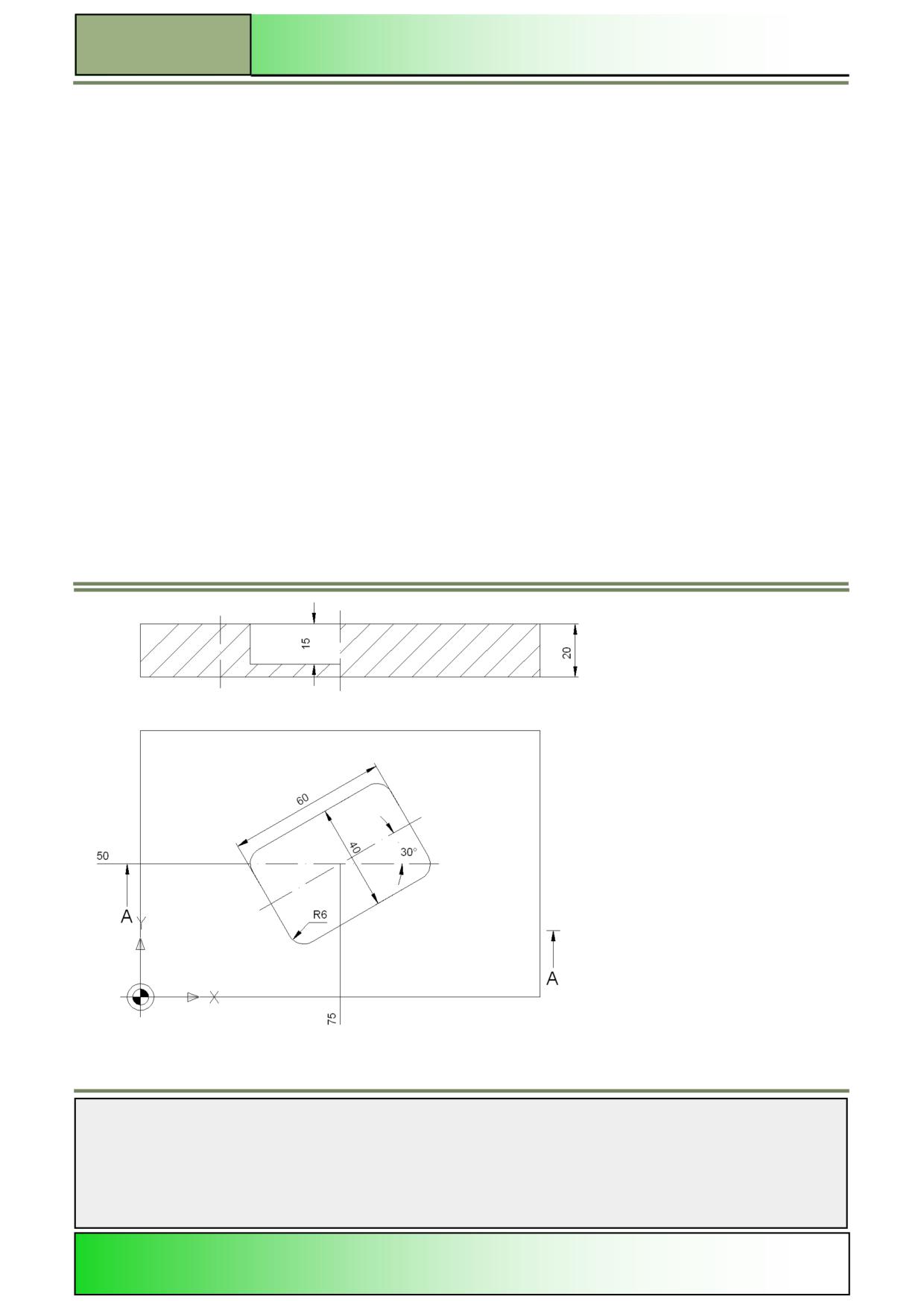
Description:
A program (slanted rectangular pocket) is to be created with the programGUIDE in ShopMill, using milling cycles and a
position pattern.
Objective:
The workpiece shown below is to be programmed and simulated afterwards.
For this the tool and technology data shown below are to be used:
The following tool- and technology data are needed for the programming:
Tool data::
Milling cutter Ø 10 mm (CUTTER_D10)
F 0,15 mm/tooth, V 120 m/min (roughing) and
F 0,08 mm/tooth, V 150 m/min (finishing)
Technology data:
The pocket is to be roughed first and later on to be finished.
Notes
M616
Page 4
828D/840Dsl SINUMERIK Operate
General geometry basics
M616
Example: Rotated rectangular pocket
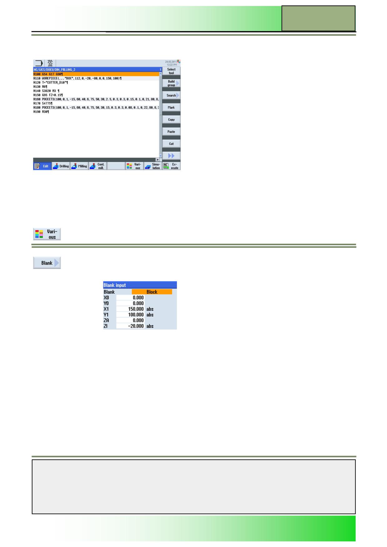
The following program is to be programmed using the milling cycle “Rectang. Pocket”.
For this, create a new programGUIDE G code program.
Give the program for example following name “DIN_MILLING_2”.
1.
Program in the first line following G code command:
N10 G54 G17 G90
2.
Insert now a blank for the simulation into the program.
Press the HSK 1.6 “Various” to open the operating area “Various”.
Press the VSK 1 “Blank” to open the parameter window for the blank input.
3.
Insert the following parameters into the parameter window:
Confirm your inputs by pressing the VSK 8 “Accept”.
The following line is inserted into the program:
N20 WORKPIECE(,,,"BOX",112,0,-20,-80,0,0,150,100)
4.
Insert now a tool into the program.
Notes
828D/840Dsl SINUMERIK Operate
Page 5
M616
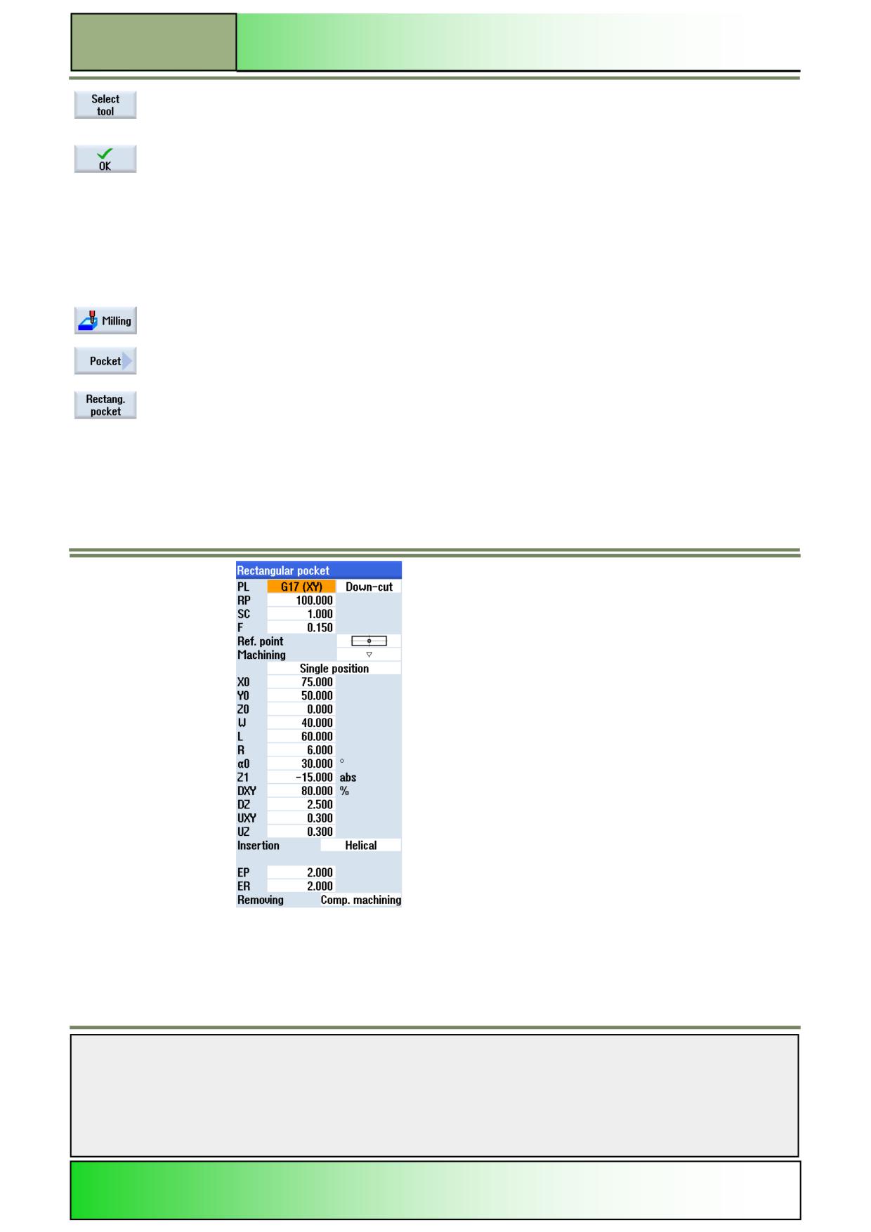
M616
Milling with programGUIDE
Press the VSK 1.1 “Select tool”.
The tool selection list in the operating area “Parameter” opens.
Use the blue cursor keys on the keyboard to select the tool “CUTTER_D10”.
Press the VSK 1.8 “OK”.
The program line N30 T="CUTTER_D10" is inserted into the program. Optionally you can pro-
gram this line by typing it into the editor.
5.
Program the following G code commands:
N40 M6
N50 S3820 M3
N60 G95 FZ=0.15
6.
Rough the rectangular pocket.
Press the HSK 1.3 “Mill.”, to open the technology “Milling”..
Press the VSK 2 “Pocket”.
Press the VSK 3 “Rectang. pocket”.
The parameter mask for the rectangular pocket cycle opens.
7.
Here, enter the values displayed below and press the VSK 8 “Accept”.
The following line is inserted into the program:
N70 POCKET3(100,0,1,-15,60,40,6,75,50,30,2.5,
0.3,0.3,0.15,0.1,0,21,80,8,3,15,2,2,0,1,2,11100,1,110)
Notes
M616
Page 6
828D/840Dsl SINUMERIK Operate
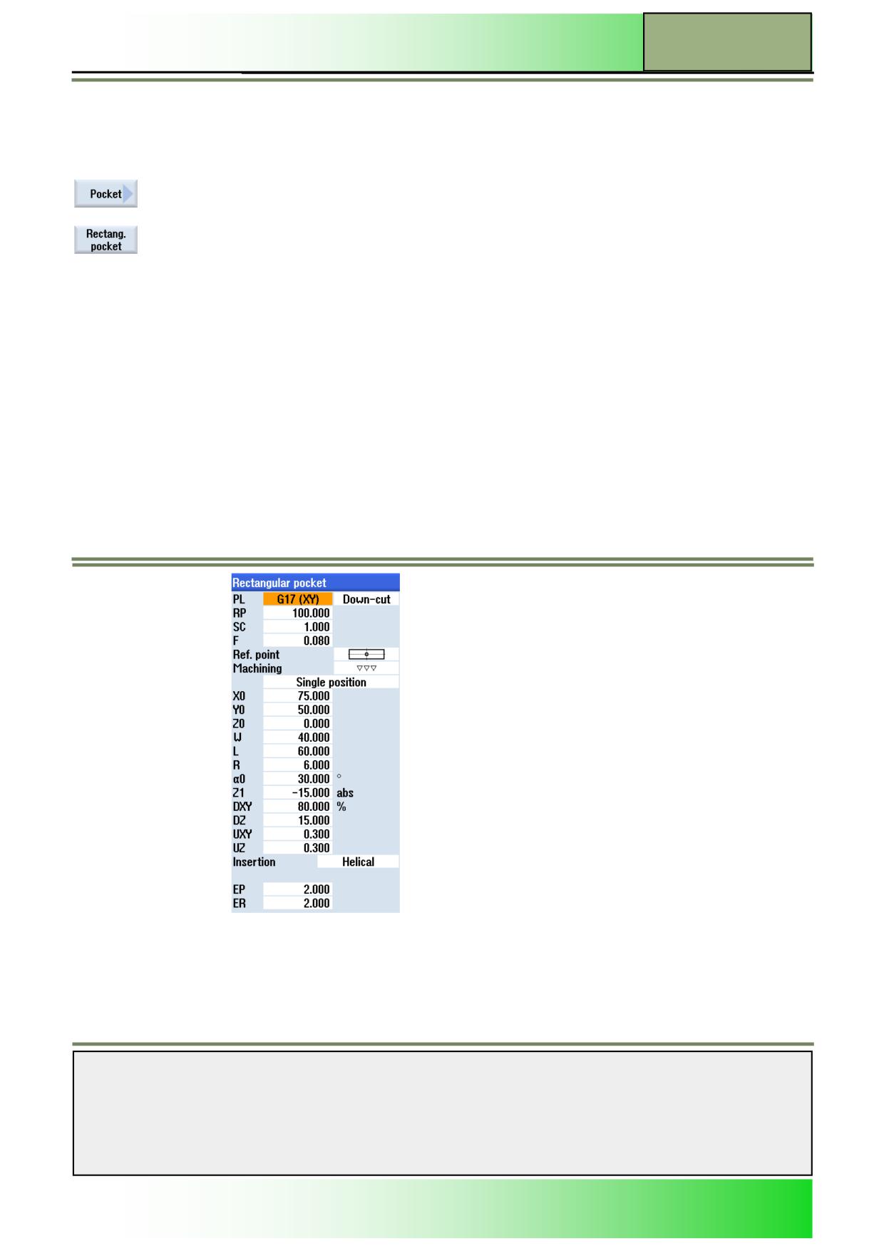
General geometry basics
M616
8.
Insert now the following G code command:
N80 S4775
9.
Finish the rectangular pocket.
Press the VSK 2 “Pocket”.
Press the VSK 3 “Rectang. pocket”.
The parameter mask for the rectangular pocket cycle opens.
10.
Insert the following values into the parameter mask and press the VSK 8 “Accept”.
The following line is inserted into the program:
N90 POCKET3(100,0,1,-15,60,40,6,75,50,30,15,0.3,
0.3,0.08,0.1,0,22,80,8,3,15,2,2,0,1,2,11100,1,110)
Notes
828D/840Dsl SINUMERIK Operate
Page 7
M616
M616
Milling with programGUIDE
11.
Program the following G code command and end the program:
N100 M30
12.
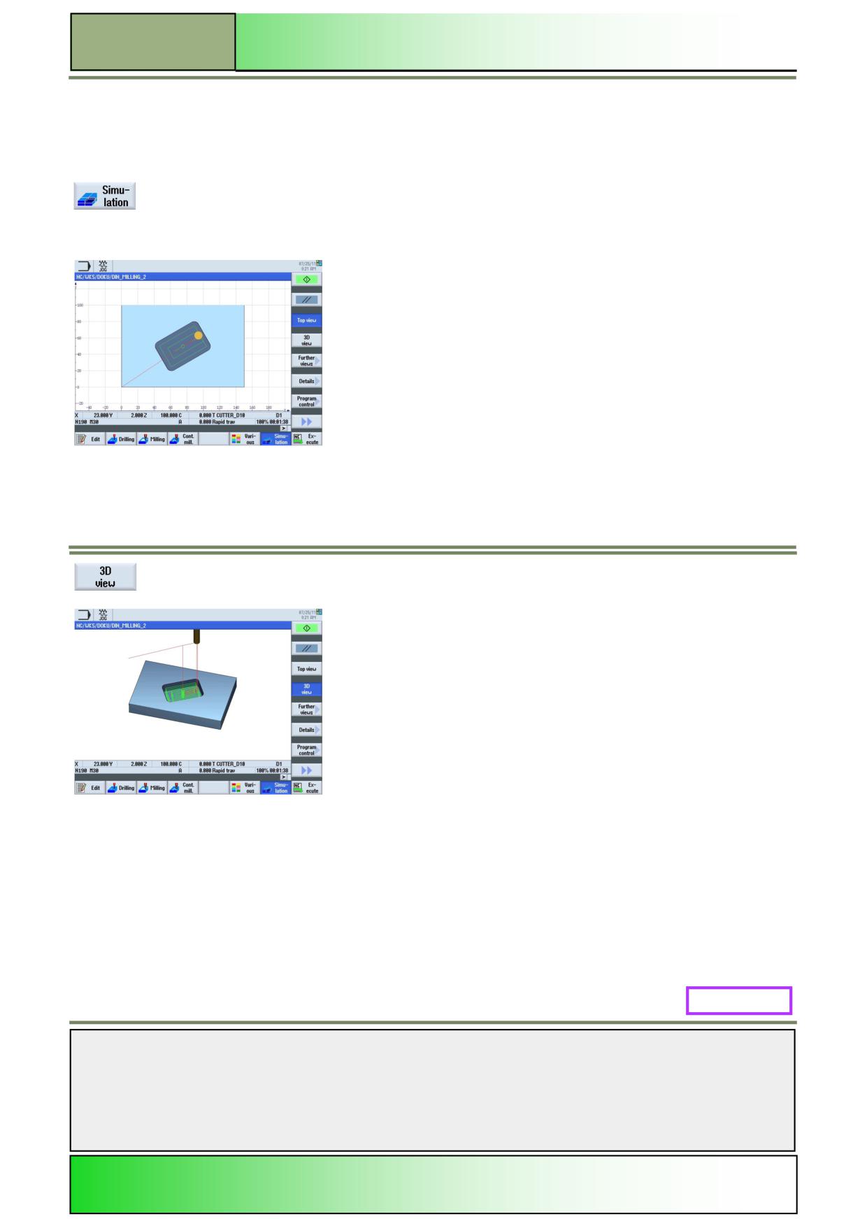
Start the Simulation of the program.
Press the HSK 1.7 “Simulation” to start the simulation run.
The control calculates the simulation parameters and opens the simulation in the simulation
window in “Top view”.
To view the simulation 3-dimensional press the VSK 1.4 “3D view”.
M616: END
Notes
M616
Page 8
828D/840Dsl SINUMERIK Operate
M609
Drilling with programGUIDE
Sinumerik
Operate
Module Description:
This module explains the programming of a simple drilling example with the programGUIDE in
ShopMill, by means of drilling cycles and position patterns
Module Objective:
Working through this module you become familiar with the technology “Drilling” by
programming a G code programs with the programGUIDE in ShopMill.
Content:
Simple programming example
This document was produced for training purposes.
828D/840Dsl SINUMERIK Operate v4.7
Page 1
M609
Siemens assumes no responsibility for its contents.
M609
M609
Page 2
828D/840Dsl SINUMERIK Operate
Drilling with programGUIDE
M609
Drilling
programGUIDE:
START
Simple
programming
example
Drilling
programGUIDE:
END
Notes
828D/840Dsl SINUMERIK Operate
Page 3
M609
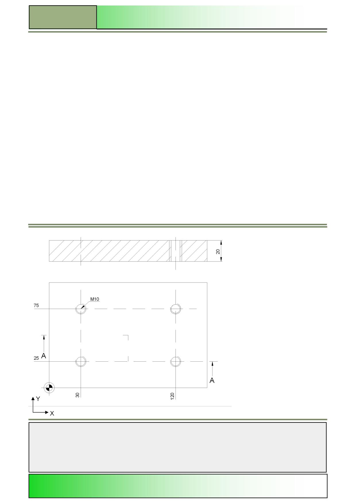
M609
Drilling with programGUIDE
Simple programming example
Description:
By using different drilling cycles (Centering, Drilling, Thread drilling) and a position pattern, a simple programGUIDE-
program (drill pattern) is to be created in ShopMill.
Aim:
The workpiece shown below is to be programmed.
Afterwards, the program is to be simulated.
The following tools and technology data are to be used.
Tool data:
Center drill 12 mm (CENTERDRILL_D12)
Drill Ø 8,5 mm (DRILL_D8.5)
Tap M10 (TAP_M10)
Technology data:
As a start position for the machining, the first programmed drill hole is to be used.
This position is approached in rapid traverse.
Notes
M609
Page 4
828D/840Dsl SINUMERIK Operate
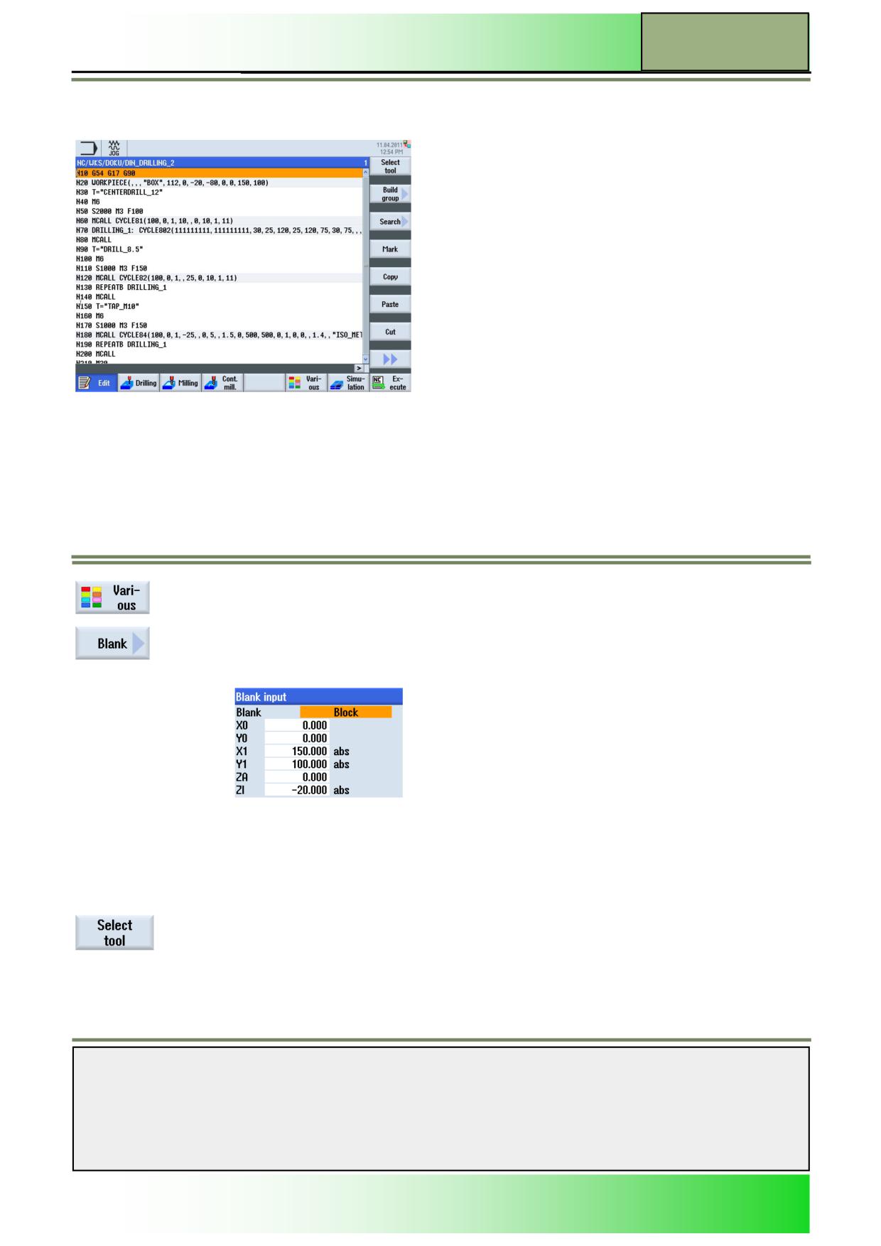
Drilling with programGUIDE
M609
Example: Drill pattern
The following program, with the call up of a drilling, center drilling and thread drilling cycle, is to be programmed:
Create a new programGUIDE-program in ShopMill.
Give the program a name, for example “DIN_DRILLING_2”.
1.
Program the first line of the program:
N10 G54 G17 G90
2.
Now insert a blank for the simulation.
For this, press the HSK 1.6 “Various” to open the operating area “Various”.
Press the VSK 1 “Blank” to open the parameter mask for the blank.
3.
Insert the values into the parameter mask like displayed below:
Confirm your inputs by pressing the VSK 8 “Accept”. The following line will be inserted into the
program:
N20 WORKPIECE(,,,"BOX",112,0,-20,-80,0,0,150,100)
4.
Insert a tool into the program.
Press the VSK 1.1 “Select tool”.
The tool selection list window opens.
Use the blue cursor keys to select the tool: “CENTERDRILL_D12”.
Notes
828D/840Dsl SINUMERIK Operate
Page 5
M609
M609
Drilling with programGUIDE
Press the VSK 1.8 “OK”.
The program line N30 T="CENTERDRILL_D12" is inserted into the program.
5.
Program the following G code commands:
N40 M6
N50 S2000 M3 F100
6.
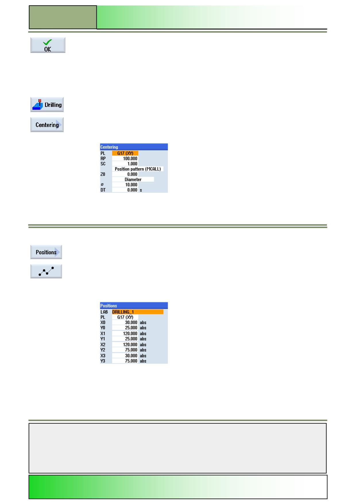
Program the center drill cycle “CYCLE 81”.
Press the HSK 1.2 “Drill.”, to open the technology “Drilling”.
Press the VSK 1 “Centering”.
The input mask for the centering cycle “CYCLE81” opens.
Insert the values into the parameter mask like displayed below:
Accept your inputs by pressing the VSK 8 “Accept”.
The following line will be inserted into the program:
N60 MCALL CYCLE81(100,0,1,10,,0,10,1,11).
7.
Insert now the position patterns (CYCLE802) for centering.
Press the VSK 7 “Positions” for selecting a position pattern.
Press the VSK 3 “Positions” to program the “CYCLE802”.
Insert DRILLING_1 into the “LAB” field to set a name for the jump marks for the repeat
positions.
Fill out the rest of the input mask like displayed below.
Confirm your inputs by pressing the VSK 8 “Accept”.
The following line will be inserted into the program:
N70 DRILLING_1: CYCLE802(111111111,
111111111,30,25,120,25,120,75,30,75,,,,,,,,,,,0,0,1)
Notes
M609
Page 6
828D/840Dsl SINUMERIK Operate
Drilling with programGUIDE
M609
8.
Program the following G code command:
N80 MCALL
9.
Insert the tool “DRILL_D8.5” into the program (see
step 4) or type into the editor the following line by hand:
N90 T="DRILL_D8.5"
10.
Program the following G code commands:
N100 M6
N110 S1000 M3 F150
11.
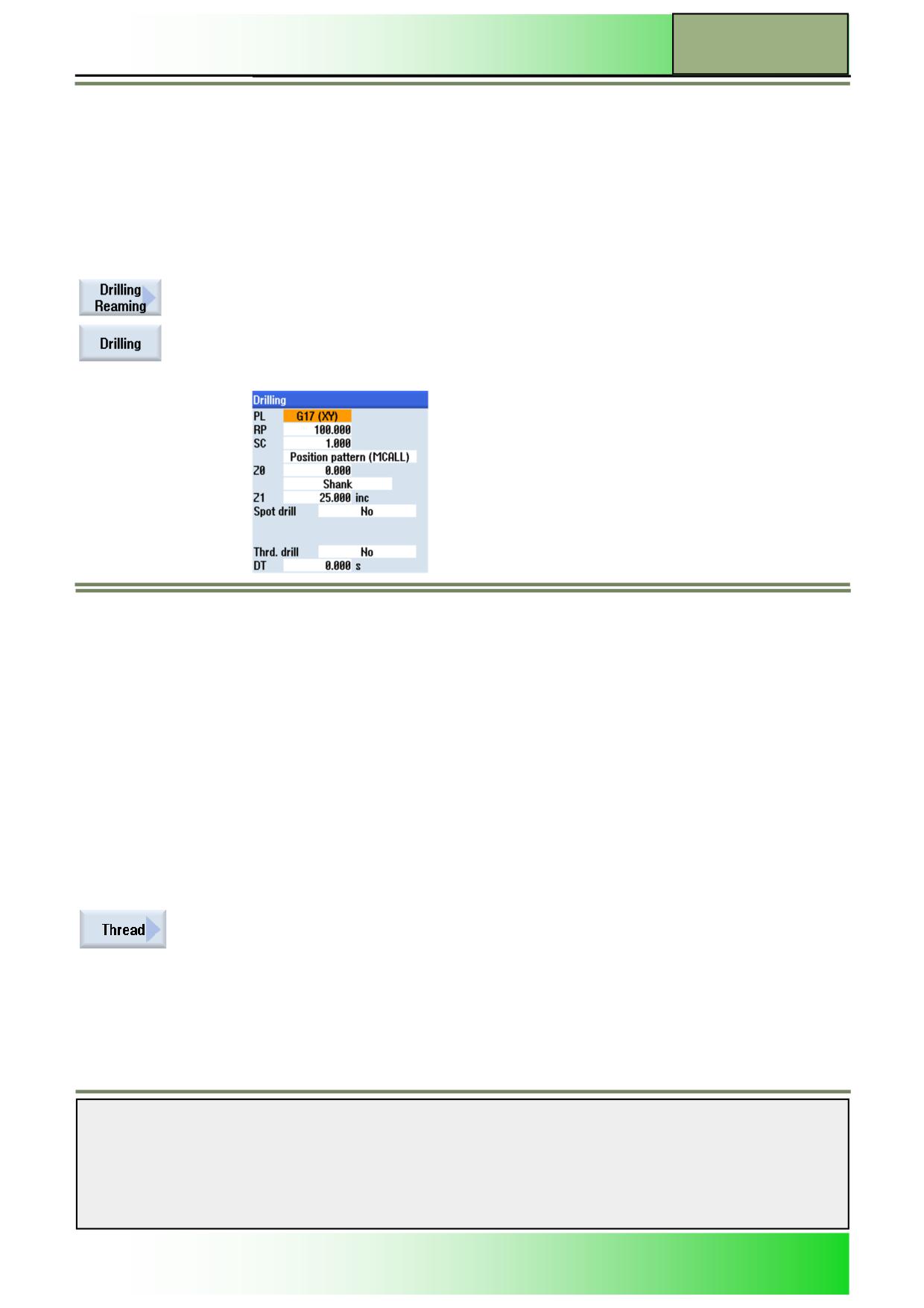
Program the cycle for drilling (CYCLE82).
Press the VSK 2 “Drilling Reaming”.
Press the VSK 3 “Drilling”.
The input mask for the drilling cycle “CYCLE82” opens.
12.
Insert the values into the parameter mask like displayed below:
Accept your inputs by pressing the VSK 8 “Accept”.
The following line will be inserted into the program:
N120 MCALL CYCLE82(100,0,1,,25,0,10,1,11).
13.
Program the following G code commands:
N130 REPEATB DRILLING_1
N140 MCALL
14.
Insert the tool TAP_M10 into the program (see
step 4) or type into the editor the following line by hand:
N150 T="TAP_M10"
15.
Program the following G code commands:
N160 M6
N170 S1000 M3 F150
16.
Finally program the cycle for the thread drilling.
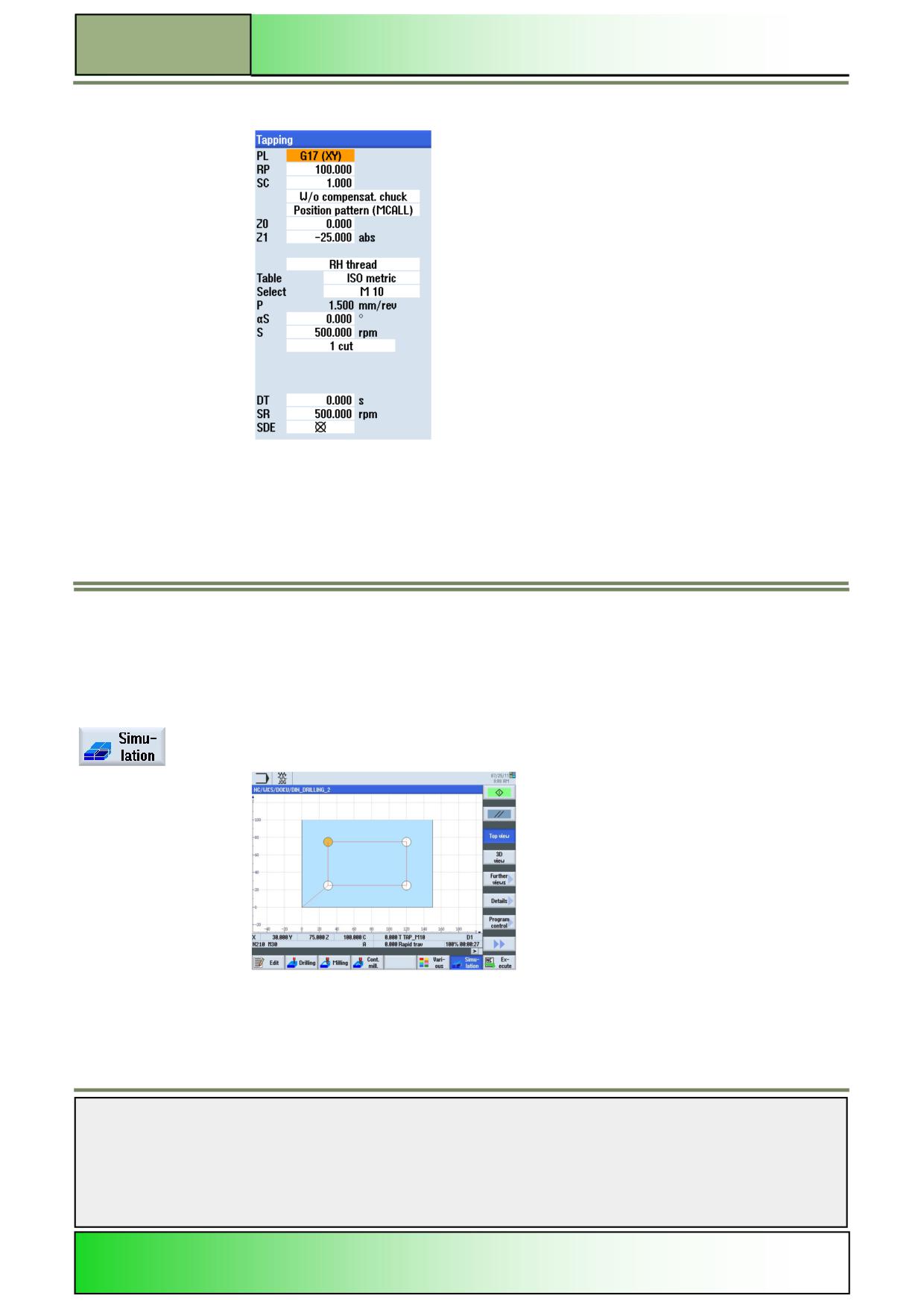
Press the VSK 5 “Thread” to open the input mask for the CYCLE84 “Tapping”.
Notes
828D/840Dsl SINUMERIK Operate
Page 7
M609
M609
Drilling with programGUIDE
17.
Insert the values into the parameter mask like displayed below:
Accept your inputs by pressing the VSK 8 “Accept”.
The following line will be inserted into the program:
N180 MCALL CYCLE84(100,0,1,-
25,,0,5,,1.5,0,500,500,0,1,0,0,,1.4,,"ISO_METRIC","M10",,1001,1001002)
18.
Program the following lines and complete the program:
N190 REPEATB DRILLING_1
N200 MCALL
N210 M30
19.
Start the simulation of the program.
Press the HSK 1.7 “Simulation” to open the simulation window.
The control calculates the simulation and shows the simulation in a top view.
Notes
M609
Page 8
828D/840Dsl SINUMERIK Operate
Drilling with programGUIDE
M609
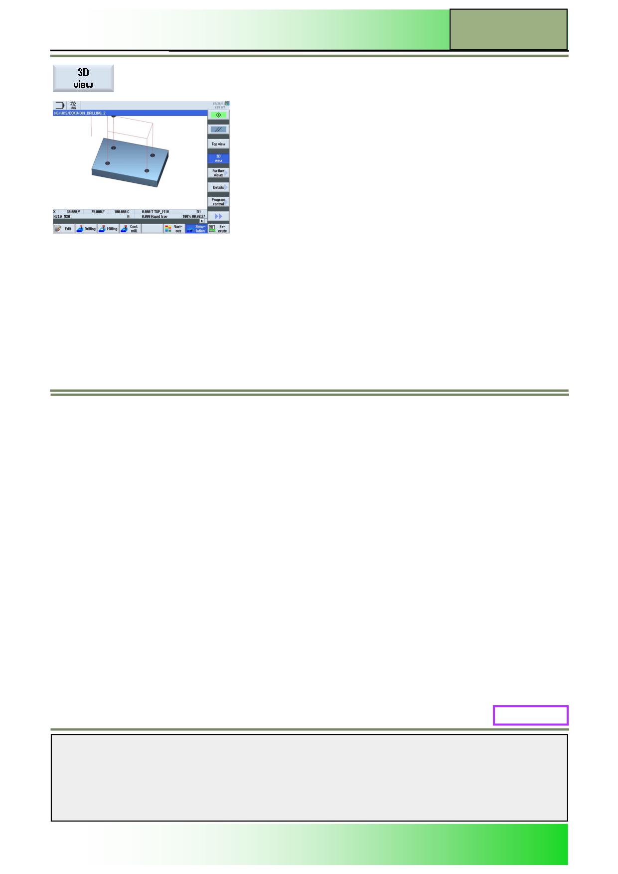
Press the VSK 1.4 “3D view“ to run the simulation in a 3-dimensional view.
M609: END
Notes
828D/840Dsl SINUMERIK Operate
Page 9
M609