SINUMERIK 840D sl. Training. Operate - Turning (2016-2020) - page 16
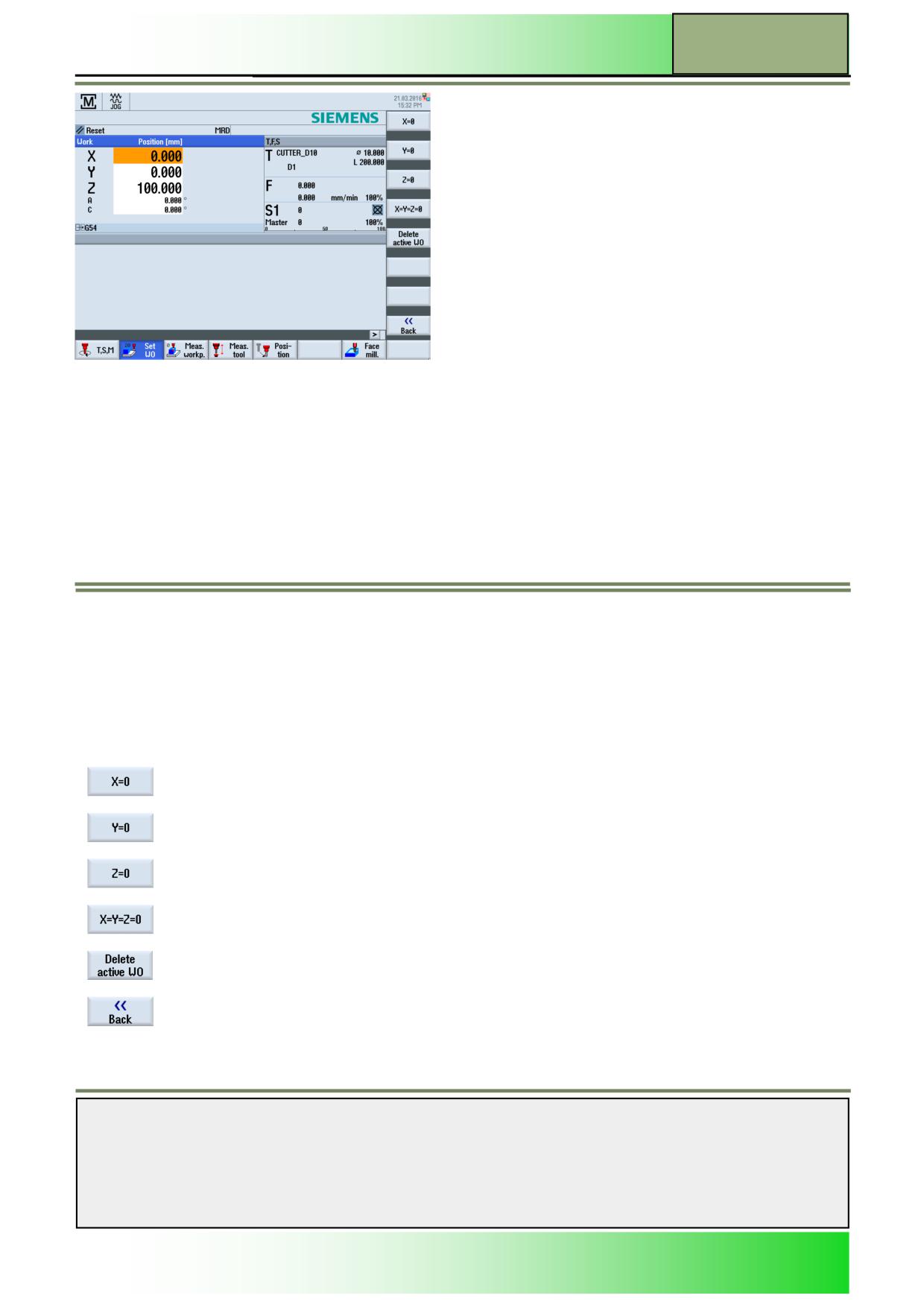
Operating mode “JOG“
M570
Input value:
By selecting an axis you can insert a value for the zero point offset in the orange marked field
(see the picture above).
The navigation through the axis-fields can be accomplished by pressing the blue “cursor-up“
and “cursor down“ keys on the keyboard.
The slider on the right side of the sub window indicates that there are more axis values availa-
ble, that can be reached by using the “cursor-down“ key.
Important:
The horizontal softkey 2 "Set WO" is only selectable if the workpiece coordinate system is
selected and a zero point offset (in this example G54) is active.
The entered values for a zero point offset of the axis will be accepted and displayed in the
workpiece coordinate system (WCS).
The difference between the original position to the new entered value will be written to the
active zero point offset.
Vertical softkey bar
Display area
Description
By pressing the VSK 1 "X=0" the position of the X-axis will be reset to zero.
By pressing the VSK 2 "Y=0" the position of the Y-axis will be reset to zero.
By pressing the VSK 3 "Z=0" the position of the Z-axes will be reset to zero.
By pressing the VSK 4 „X=Y=Z=0“ the position of the X/Y/Z-axis will be reset to zero.
By pressing the VSK 5 "Delete active WO" the zero point offset of all axes is set back to zero.
By pressing the VSK 8 "Back" you switch back to the main screen of the Sinumerik Operate.
Note:
After setting a position or deleting a zero point offset you switch back automatically to the main screen of the Sinumerik
Operate.
Notes
828D/840Dsl SINUMERIK Operate
Page 13
M570
M570
Operating mode “JOG“
Measure workpiece
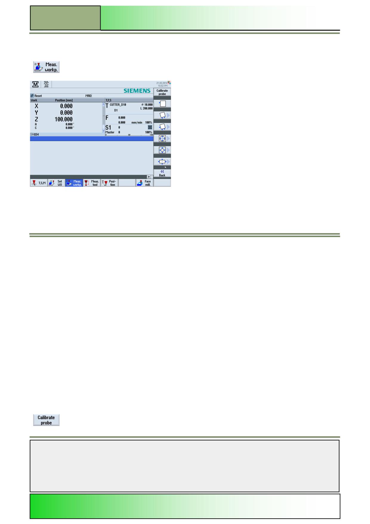
Selecting the function “Measure workpiece“
In the operating area “Machine“ under the operating mode “JOG“ press the HSK 3 "Meas.
workp." to open the “Measure workpiece“ window shown below.
The reference point for programming a workpiece is always the workpiece zero. You can determine the workpiece zero on
the following workpiece elements:
Edges (Set edge, Align edge)
Corner (Rectangular corner)
Hole (1 Hole, 2 Holes, 3 Holes, 4 Holes))
Spigot (Circular spigot, rectangular spigot)
The workpiece zero can be measured either manually or automatically.
Measuring manually:
For manual measuring their are parameters that depend upon tool type, and therefore are only available for the particular
case. The tool must be manually approached to the workpiece. You can use edge probes, sensing probes, or dial gauges
with known radii and lengths. You can also use any other tool of which you know the radius and length. The tools used for
measuring must not be electronic probes.
Measuring automatically:
For automatic measurements always use electronic 3-D or mono workpiece probes. You must calibrate the electronic work-
piece probes beforehand. First position the workpiece probe manually. As soon as you start the process with the "CYCLE
START" key, the workpiece probe automatically approaches the workpiece at measuring feedrate and then returns to the
starting position at rapid traverse. The machine manufacturer must first set the appropriate machine parameters (e.g. the
measuring feedrate).
Note: During all measurements the override of the feedrate should be set to 100%.
Vertical softkey bar
Display area
Description
By pressing the VSK 1 “Calibrate probe“ the input mask for “Calibrate probe“ opens.
Notes
M570
Page 14
828D/840Dsl SINUMERIK Operate
Operating mode “JOG“
M570
Display area
Description
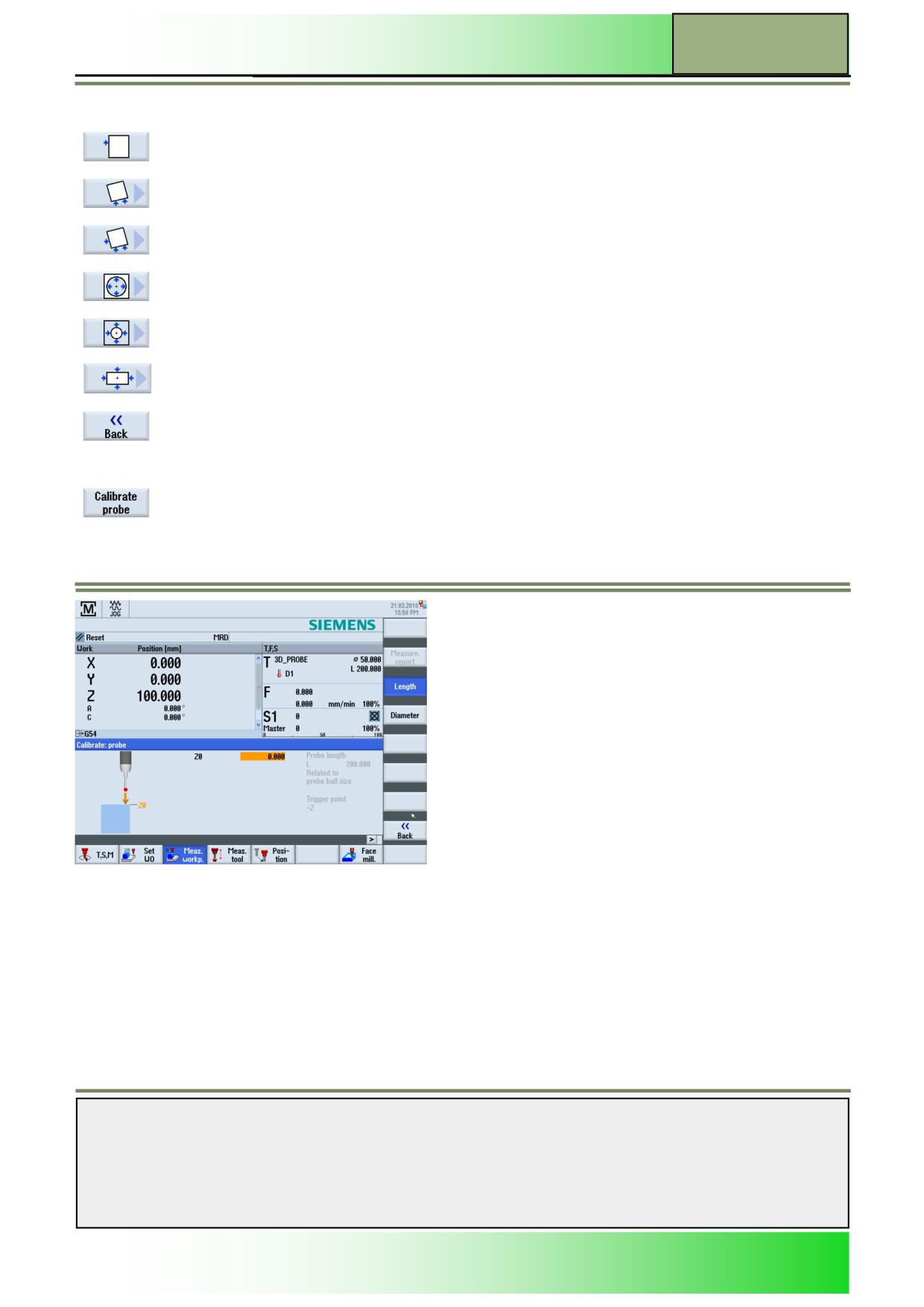
By pressing the VSK 2 “Set edge“ the “Set edge“ window opens.
By pressing the VSK 3 “Align edge” the “Align edge” window opens.
By pressing the VSK 4 “Rectangular corner” the “Rectangular corner” window opens.
By pressing the VSK 5 “1 Hole” the “1 Hole” window opens.
By pressing the VSK 6 “1 Circular spigot” the “1 Circular spigot” window opens.
By pressing the VSK 7 “1 Rectangular spigot” the “1 Rectangular spigot” window opens.
By pressing the VSK 8 "Back" you switch back to the main screen of the Sinumerik Operate.
Selecting the function “Calibrate probe”
By pressing the HSK 3 “Meas. workp.” and the VSK 5 “Calibrate probe” (in operating area
“Machine” and operating mode “JOG”) the following input screen will be displayed.
Notes
828D/840Dsl SINUMERIK Operate
Page 15
M570
M570
Operating mode “JOG“
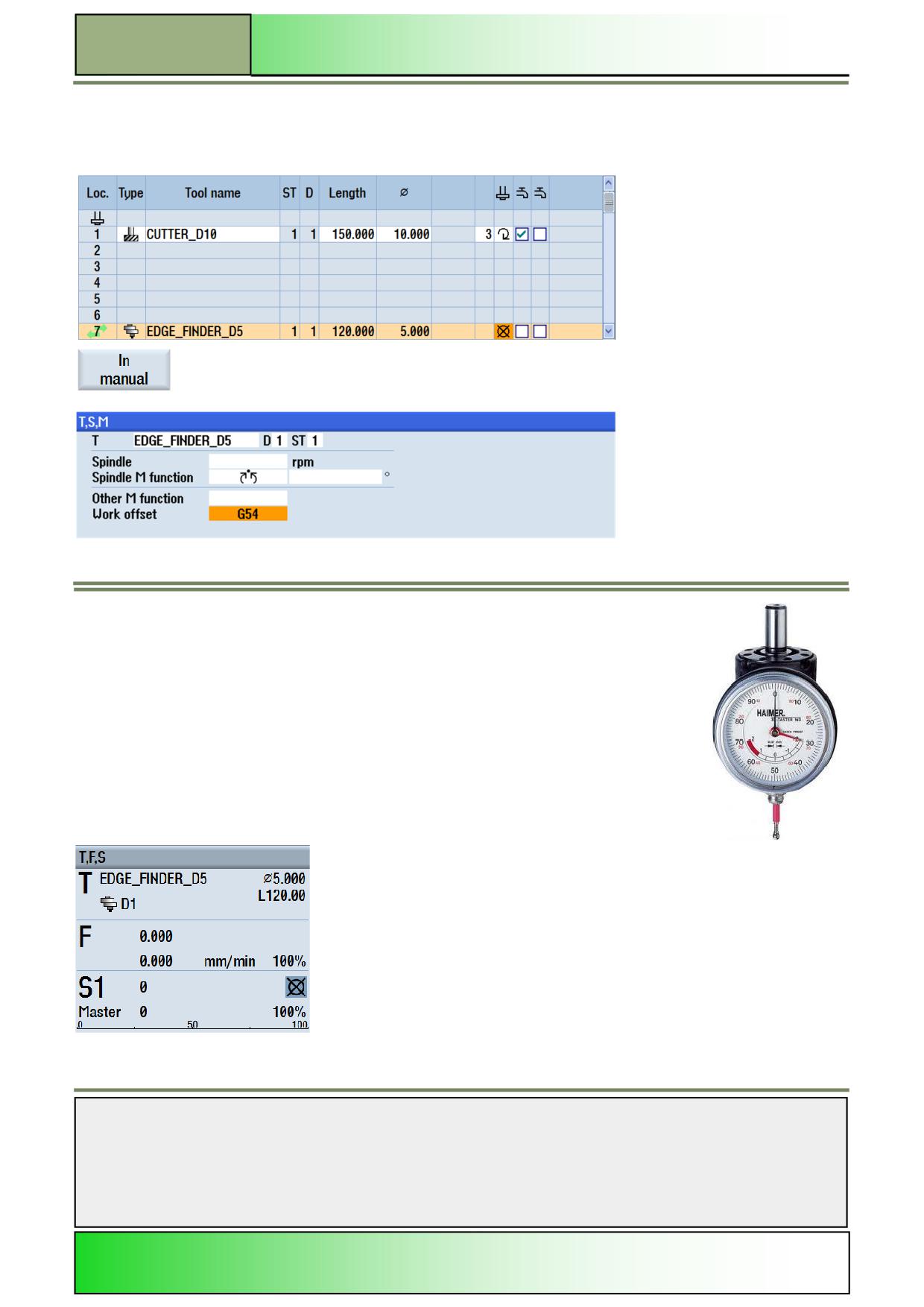
Example of two measurment functions “Set edge“ and “Tapinto rectangular“
As already described in section 3, a mechanical probe to be created in the tool list and using “T, S, M“ loaded into the
spindle.
With the VSK 1 "In Manual", the tool is transferred into the input window of T, S, M.
Additional functions of the input mask of "T, S, M" are briefly explained.
The "Spindle M function", a mechanical probe is
oriented for easy reading.
The "Stop position" can be any angle.
In addition, the offset can be activated, in which the measured values are to be entered.
The technology window will display the measuring tool from the tool list, with details of length
and edge number.
Note:
The part to be measured is "Set edge" on the workpiece surface with the meas-
urement function with 1mm oversize and is in the middle of the workpiece, meas-
ured with the measuring function "Rectangular spigot" .
Notes
M570
Page 16
828D/840Dsl SINUMERIK Operate
Operating mode “JOG“
M570
Measure workpiece zero “Set edge”
The workpiece lies parallel to the coordinate system on the work table. One reference point will be measured in one of the
axes (“X”, “Y”, “Z”).
The following requirements must be fulfilled:
Any tool can be loaded in the spindle for scratching when measuring the workpiece zero manually.
An electronic workpiece probe is loaded in the spindle and activated when measuring the workpiece zero automatically.
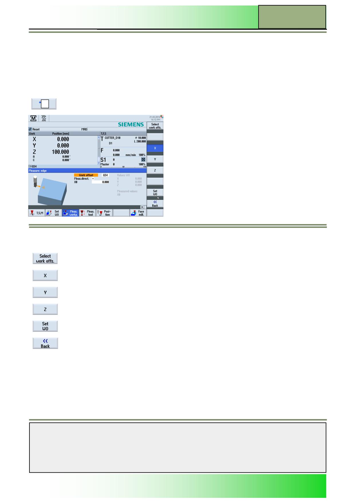
By pressing the HSK 3 “Meas. workp.” and the VSK 2 “Set edge“, in the operating area “Machine“
and operating mode “JOG“, the following screen will be displayed.
Vertical softkey bar (VSK)
Display area
Description
By pressing the VSK 2 “Select work offset“ a list of the work offsets opens.
See module B573 - “Operating area Parameter“.
By pressing the VSK 3 “X“ the measured values for the X-axis will be determined.
By pressing the VSK 4 “Y“ the measured values for the Y-axis will be determined.
By pressing the VSK 5 “Z“ the measured values for the Z-axis will be determined.
By pressing the VSK 7 “Set WO“ the values will be accepted for the work offset.
By pressing the VSK 8 “Back“ you switch back to the “Measure workpiece“ main screen .
Notes
828D/840Dsl SINUMERIK Operate
Page 17
M570
M570
Operating mode “JOG“
Parameters of "Set edge"
Parameter
Description
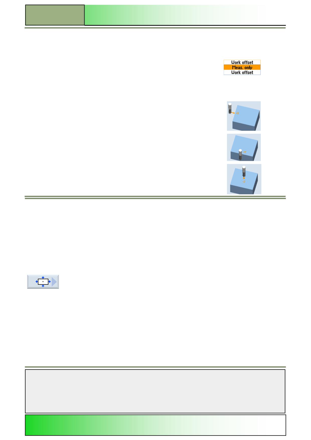
Work offset:
Alternative parameters
Measure only
The measured values are computed and displayed without
changing the coordinate system.
Work offset
Measurement
direction:
The selection of the axes directions “X”/”Y”/”Z” is made by the
X
vertical softkey bar. With the measurement direction (+ or -) it is
determined whether the workpiece will be approached from a
positive or negative “X”- or “Y”-direction.
By selection of the axis direction “Z it is only possible to approach
the work piece from a negative Z direction.
Y
Z
Reference point
X0, Y0, Z0
Workpiece zero measure "Rectangular spigot"
The workpiece is parallel to the coordinate system on the work table and is a rectangle. About 4 measuring points of the
center of the rectangle is determined.
The following requirements must be met:
Any tool can be used for scratching when loaded into the spindle for workpiece zero manual measuring.
An electronic workpiece probe when loaded into the spindle and activated will measure the workpiece zero automati-
cally.
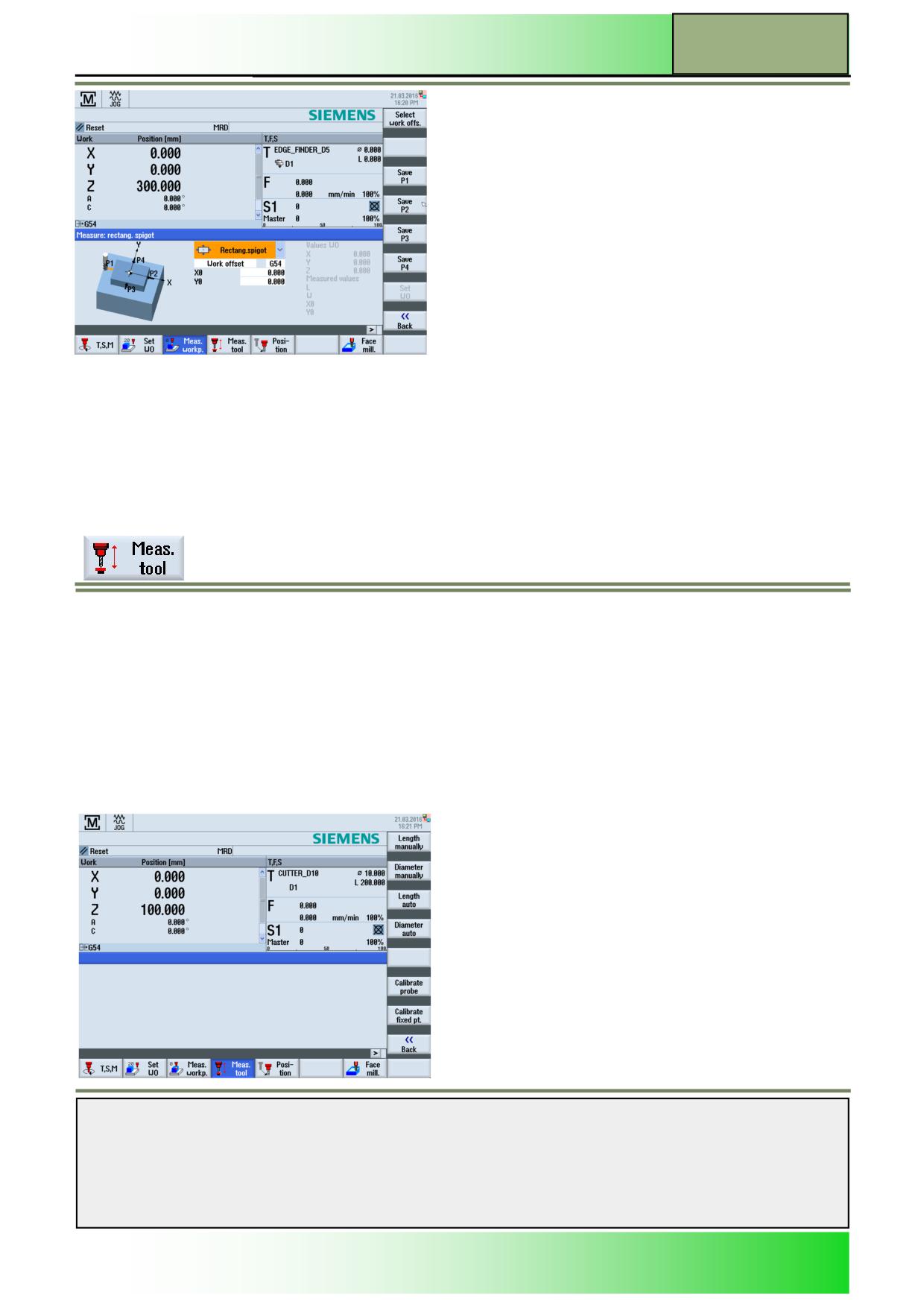
Pressing the VSK 6 "Rectangular spigot" softkey in the function "Meas. Workp. "
(" Machine "in the" JOG ") appears on the screen the following input mask.
Vertical softkey bar (VSK)
See page 20, Measure workpiece "Set edge".
Parameter Measure workpiece "Rectangular spigot"
The following parameters of Measure workpiece "Set edge" are also at work measure "Rectangular spigot":
[Zero offset G54, X0, Y0]
Notes
M570
Page 18
828D/840Dsl SINUMERIK Operate
Operating mode “JOG“
M570
Measuring a tool
Selecting the function “Measure tool“
The geometries of the machining tool must be taken into consideration when executing a part program. These are stored
as tool offset data in the tool list. Each time the tool is called, the control considers the tool offset data. When programming
the part program, you only need to enter the workpiece dimensions from the production drawing. After this, the controller
independently calculates the individual tool path.
You can determine the tool offset data, i.e. the length and radius or diameter, either manually or automatically with tool
probes.
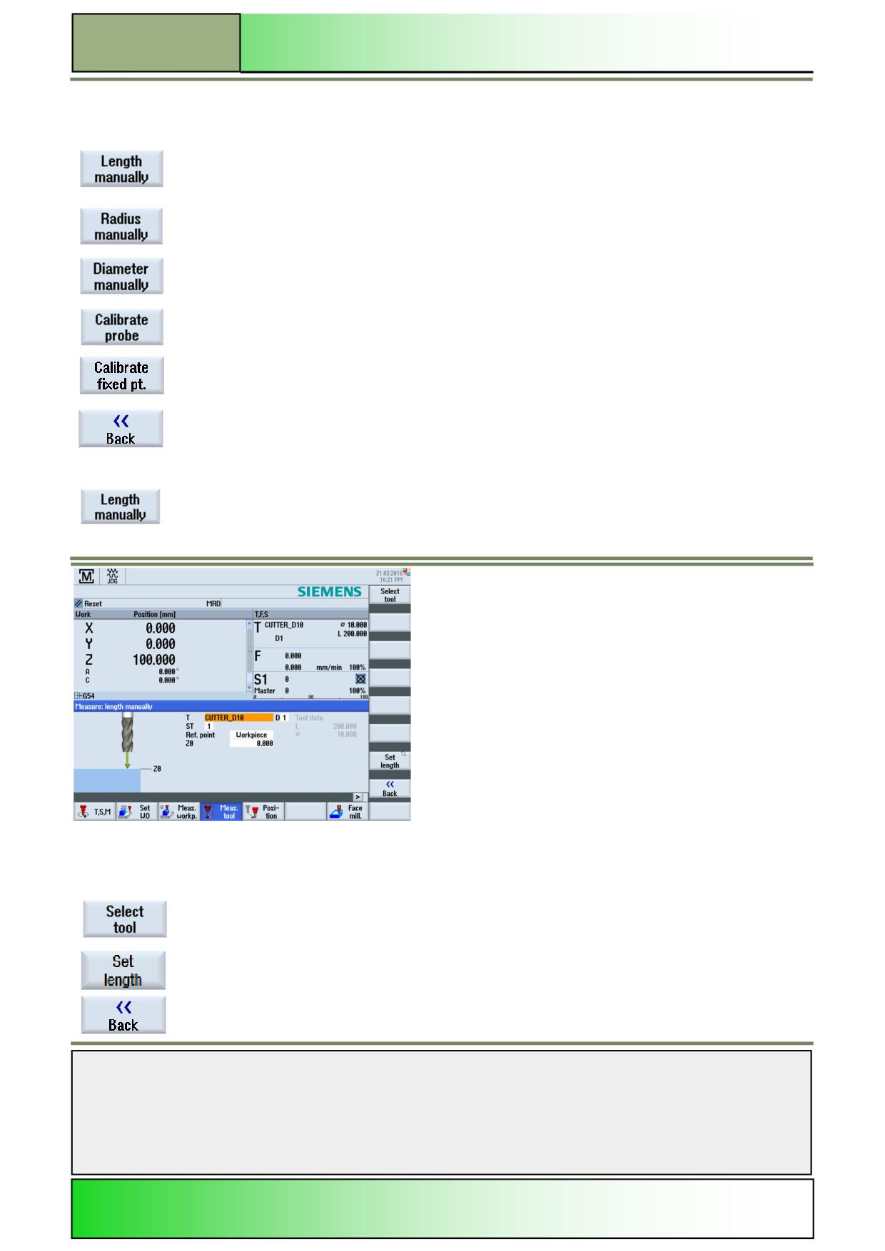
By pressing the HSK 4 “Meas. tool“ in the operating mode “JOG” under the operating area
“Machine” the following window opens:
Measuring a tool manually
For manual measurement, move the tool manually to a known reference point to determine the tool length and the radius or
diameter. The control then calculates the tool offset data from the position of the tool carrier reference point and the refer-
ence point.
With the measuring of the tool length either the workpiece or a fixed point in the machines coordinate system, e.g. a load
cell or a fixed point in conjunction with a distance meter, can be used as a reference point. The position of the workpiece is
specified during the measurement. The position of the fixed point however must be announced before the measurement.
With the determination of the radius or diameter the workpiece always serves as the reference point.
Hint:
Depending on the setting in a machine data either the radius or the diameter of the tool can be measured.
Note:
Refer to the machine manufacturer's specifications.
Notes
828D/840Dsl SINUMERIK Operate
Page 19
M570
M570
Operating mode “JOG“
Vertical softkey bar (VSK)
Display area
Description
By pressing the VSK 1 ”Length manually” the “Length manually” input mask opens.
By pressing the VSK 2 “Radius manual“ or rather “Diameter manual“ the input mask “Radius
manual“ or rather “Diameter manual“ opens.
By pressing the VSK 6 ”Calibrate probe” the “Calibrate probe” input mask opens.
By pressing the VSK 7 ”Calibrate fixed pt.” the “Calibrate: fixed point” input mask opens.
By pressing the VSK 8 “Back“ you jump back to the “Meas. tool” screen of the Sinumerik
Operate.
Measure tool “Length manual”
By pressing the HSK 4 “Meas. tool” and the VSK 1 “Length manual“ (in the operating area
“Machine“ under the operating mode “JOG”) the following input mask opens.
Vertical softkey bar (VSK)
Display area
Description
By pressing the VSK 1 “Select tool“ the tool list opens.
See module M573 - “Operating area Parameter“.
By pressing the VSK 7 “Set length“ the entered values will be accepted.
By pressing the VSK 8 “Back“ you jump back to the “Measure tool” screen of the Sinumerik
Operate.
Notes
M570
Page 20
828D/840Dsl SINUMERIK Operate

Operating mode “JOG“
M570
Parameters of measure tool “Length manual“
Parameter
Description
T
Tool name
Alternatively you can select a tool via the VSK 1 “Select tool”.
D
Edge number
(1 to 9)
ST
Replacement tool
(01- 99)
Ref. point
Workpiece or Fixed pt.
Z0
Workpiece edge
Procedure for Measuring tool “Length manual”
1.
Load the tool in the spindle you want to measure.
2.
In the operating mode “JOG“ press the HSK 4 “Meas. tool”.
3.
Press the VSK 1 “Length manual”.
The “Length manual” input screen opens.
4.
Press the VSK 2 “Tool“.
Select a tool from the “Tool list” that opens immediately after pressing the softkey.
5
Press the VSK 1 „In manual“ to switch back with the selected tool to the “Length manual” window.
4.
Select the cutting edge number “D” and the number of the replacement tool “ST”.
5.
Approach the workpiece in the Z direction, scratch it with a rotating spindle
6.
Enter the set position “Z0” of the workpiece edge.
7.
Press the VSK "Set length" softkey.
The tool length is calculated automatically and entered in the tool list.
Notes
828D/840Dsl SINUMERIK Operate
Page 21
M570
M570
Operating mode “JOG“
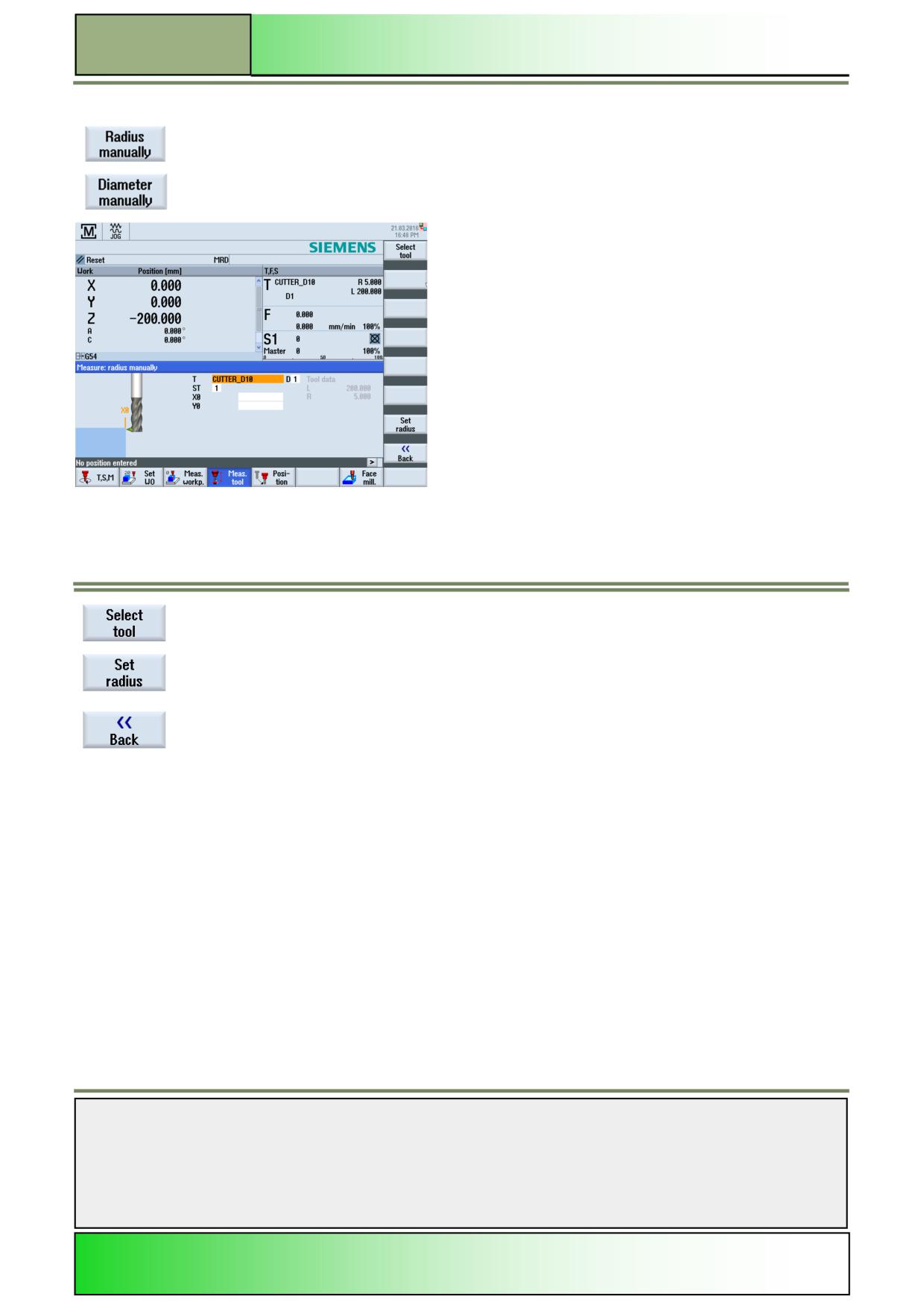
Measure tool ”Radius manual“ or “Diameter manual”
By pressing the HSK 4 “Meas. tool” and the VSK 2 “Radius manually“ or “Diameter
manually” (in the operating area “Machine“ and operating mode “JOG”) the following input
mask opens.
Vertical Softkey bar (VSK)
Display area
Description
By pressing the VSK 2 “Select tool” the tool list opens.
By pressing the VSK 7 “Set diamet.“ (or “Set radius.”) all entered values will be accepted.
By pressing the VSK 8 “Back“ you jump back to the “Measure tool” screen of the Sinumerik
Operate“.
Parameters measure tool “Radius manual“ or “Diameter manual”
The following parameters of the function “Length manual” are used also with “Radius manual” and “Diameter manual”:
[T, D, ST]
Beside the before mentioned parameters you find the following additional parameters in the “Radius manual” or “Diameter
manual” window:
Parameter
Description
X0
Workpiece edge
Y0
Workpiece edge
Notes
M570
Page 22
828D/840Dsl SINUMERIK Operate
Operating mode “JOG“
M570
Procedure for measuring the tool “radius manual” (or “diameter manual” )
1.
Load the tool you want to measure in the spindle.
2.
In the operating mode “JOG“ and operating area “Machine” press the HSK 4 “Meas. tool“.
3.
Press the VSK 2 “Radius manual“ ( or “Diameter manual“).
4.
Select the cutting edge number “D” and the number of the replacement tool “ST” of the tool.
5.
Approach the workpiece in the X- or Y-direction and perform scratching with the spindle rotating in the opposite
direction.
6.
Specify the setpoint position “X0” or “Y0” of the workpiece edge.
7.
Press the "Set radius" or "Set diameter" softkey.
The tool radius or diameter is calculated automatically and entered in
the tool list.
Selecting the function “Calibrate fixed point”
If you want to measure your tools manually, you must first determine the height of the fixed point on the machine table with
reference to the machine zero.
The fixed point can be either a measuring gauge of a known height or an electronic height gauge of known height. Place
the gauge in the working area of the machine (e.g on the machine table) and align it relative to the machining axes.
You can use any type of tool to measure the fixed point.
You must enter the length and radius/diameter of the tool in the tool list beforehand.
Note:
Refer to the machine manufacturer's specifications.
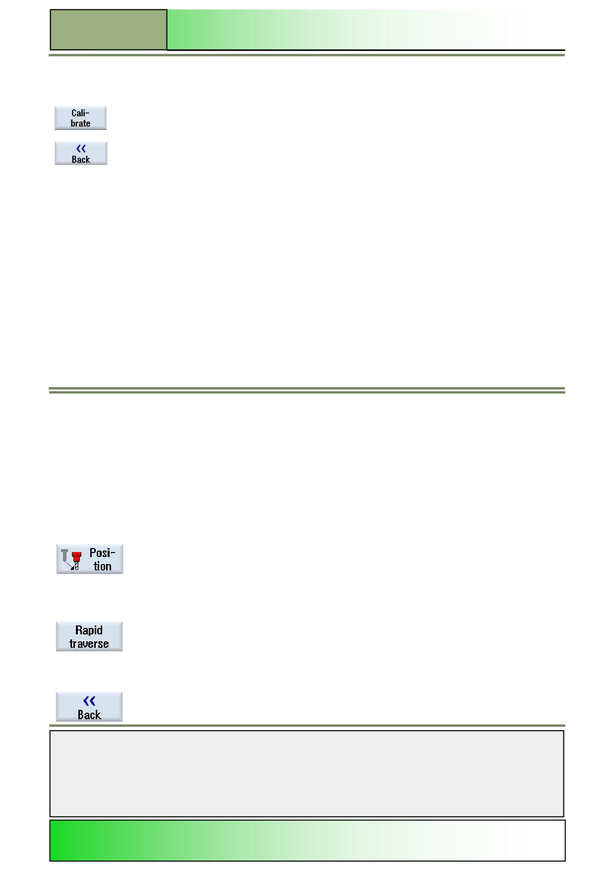
By pressing the HSK 4 “Meas. tool” and the VSK 7 “Calibrate fixed pt.“ (in the operating area
“Machine“ and operating mode “JOG”) the “Fixed point calibration” window opens.
Notes
828D/840Dsl SINUMERIK Operate
Page 23
M570
M570
Operating mode “JOG“
Vertical softkey bar (VSK)
Display area
Description
By pressing the VSK 7 “Calibrate“ the control calculates the fixed point height.
By pressing the VSK 8 “Back“ you switch back to the “Measure tool” window.
Parameters of measure tool “Calibrate: fixed height”
By calibrating the probe the following parameters are displayed:
Parameter
Unit
Description
DZ
[mm]
Is the distance from the table to top of the fixed point gauge.
procedure for tool measure “Calibrating fixed point”
1.
Move the calibration tool until it is approximately over the centre of the measuring surface of the
fixed point gauge
2.
In the operating mode “JOG“ press the HSK 4 “Meas. tool“.
3.
Press the VSK 6 “Calibrate fixed pt.”.
4.
Use the JOG keys in “Incremental mode, or the handwheel to position the tool at the fixed posi-
tion height.
5.
Press the “Calibrate“ softkey to calibrate the fixed point.
Position
Selecting the function “Position“
In order to implement simple machining sequences, you can traverse the axes to certain positions in manual mode.
Note:
The feedrate/rapid traverse override is active during traversing.
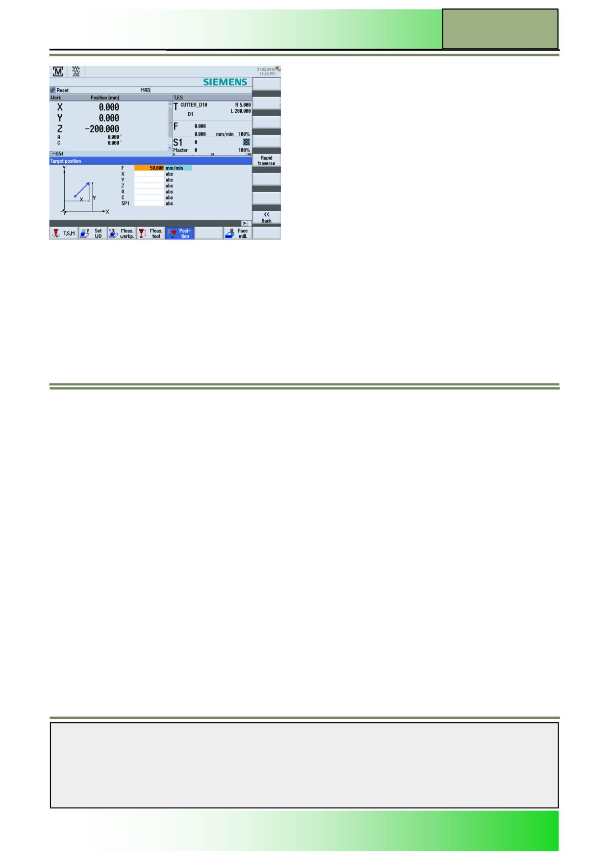
By pressing the HSK 6 “Position” in the Operating area “Machine” and oper-
ating mode “JOG” the following input mask will be shown on the screen:
Vertical softkey bar (VSK)
Display area
Description
By pressing the VSK 5 “Rapid” the value of the set
machine data for feed rate velocity in JOG is taken over in the parameter “F” (feed).
Hint:
The VSK 5 “Rapid traverse” can also be pressed if the input field parameter “F” is not the
active input field (highlighted in orange)
By pressing the VSK 8 “Back” you switch back to the main screen of the Sinumerik Operate.
Notes
M570
Page 24
828D/840Dsl SINUMERIK Operate
Operating mode “JOG“
M570
Parameters of “Position”
Parameter
Unit
Description
F
[mm/min]
Feed
[mm/tooth]
X
[mm]
Target position of the selected axes
[abs/inc]
Y
Note:
Several target positions can be entered.
B-axis and C-axis are manufacturer specif-
Z
ic.
Follow the documentation of the machine manufacturer.
SP
[Degree]
Target angle [abs, inc]
Procedure for positioning the axes
1.
Select the “JOG” operating mode.
2.
Press the HSK 6 “Position”.
3.
Specify the desired value for the feedrate “F”.
- OR -
3.
Press VSK 5 "Rapid".
*Rapid tr.* is displayed in the input field “F”.
4.
Enter the target position or the target angle for the axis or axes to be traversed.
5.
Press the "CYCLE START" button on the machine control panel.
The axis is traversed to the specified target position.
Note:
If target positions were specified for several axes, the axes are traversed simultaneously.
Notes
828D/840Dsl SINUMERIK Operate
Page 25
M570
M570
Operating mode “JOG“
Face milling
Selecting the function “Face milling”
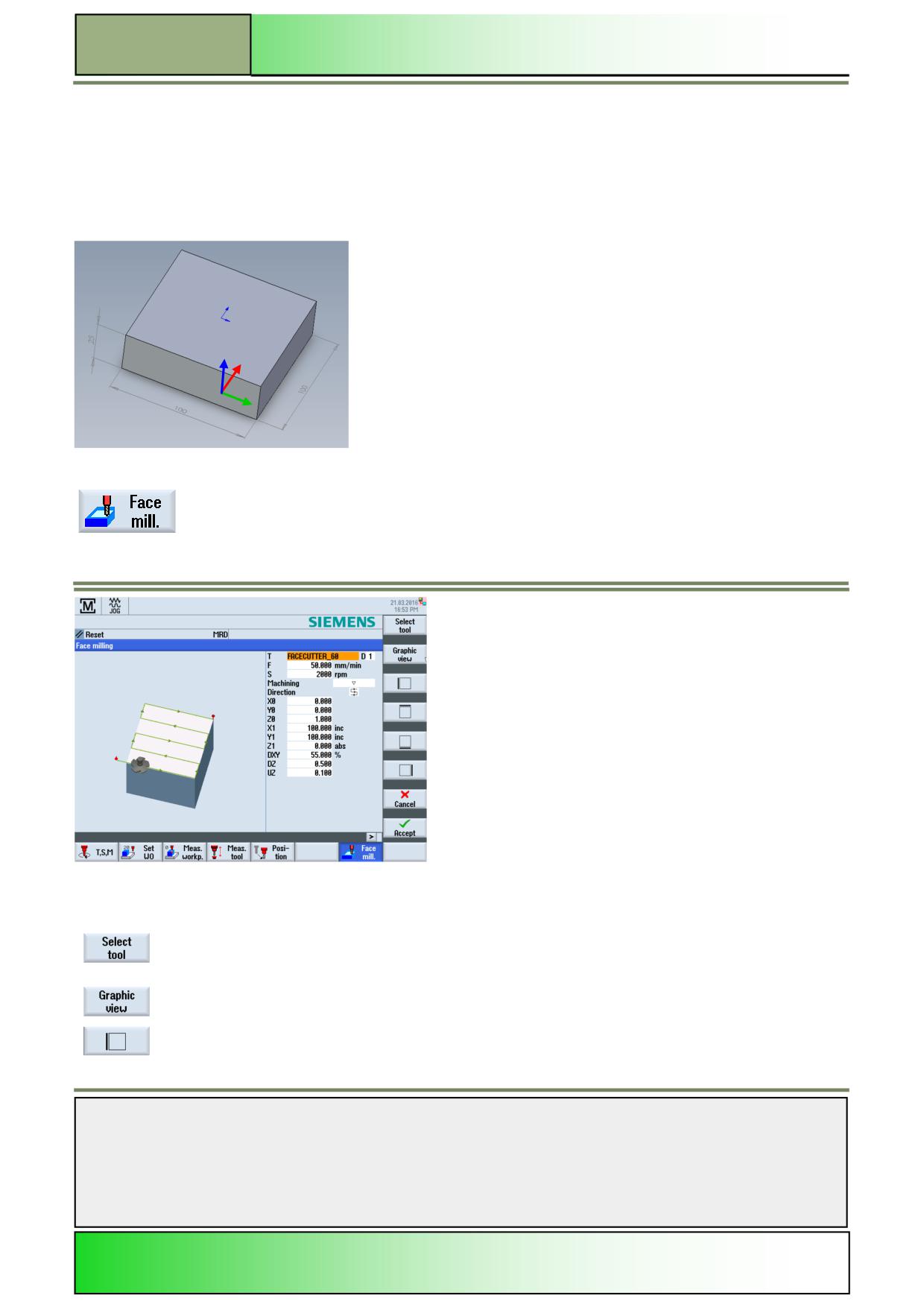
You can use this cycle to face mill any workpiece. A rectangular surface is always machined.
“Measuring the workpiece" is already mentioned in section 5. The input mask “Face milling” is described in relation to a
workpiece with dimensions 25x100x100 mm, with 1mm to be removed leaving a thickness of 24mm.
The zero point in the X and Y axis has been determined in the workpiece
center with measuring function "Rectangular spigot" and the Z axis was "set
edge" with Z value +1 mm determined and stored at zero 1 (G54).
By pressing the HSK 7 “Face mill.” in the Operating area “Machine” and operating mode
“JOG” the following input mask will be shown on the screen.
Vertical softkey bar (VSK)
Display area
Description
By pressing the VSK 1 „Select tool“ you can insert a tool. Select the desired tool in the tool list
(e.g FACEMILL_50 with the orange selection cursor and press VSK 1 “In program”
With VSK 2 ”Graphic view” you can switchover between help screen and graphical view.
With VSK 3 "lateral limitation left" you can specify the lateral limitation in “X-” direction.
Notes
M570
Page 26
828D/840Dsl SINUMERIK Operate
Operating mode “JOG“
M570
Vertical softkey bar (VSK)
Display area
Description
With VSK 4 "lateral limitation top" you can specify the lateral limitation in “Y+” direction.
With VSK 5 "lateral limitation right" you can specify the lateral limitation in “X+” direction.
With VSK 6 "lateral limitation bottom" you can specify the lateral limitation in “Y-” direction.
By pressing the VSK 7 “Cancel” you can escape the screen “face milling”.
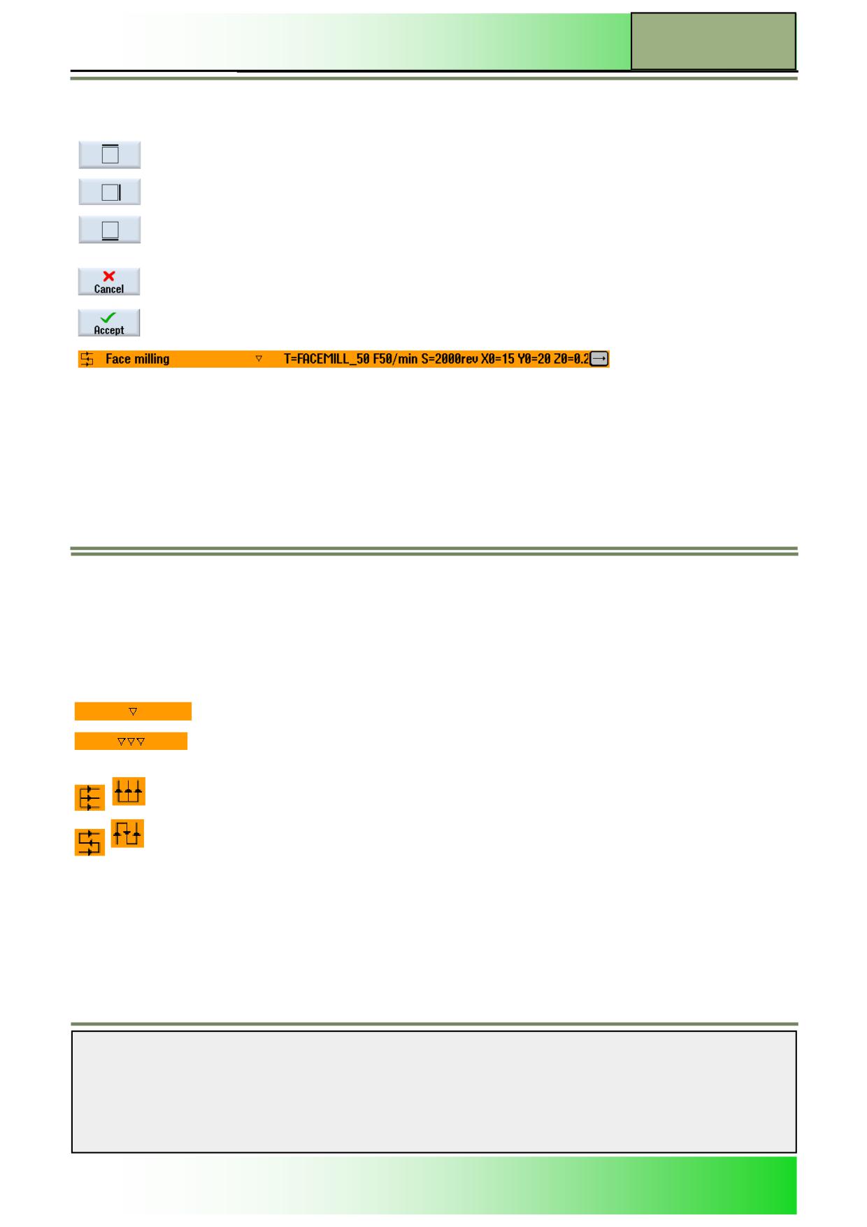
With pressing of VSK 8 ”Accept” the following program block is generated:
With “CYCLE START“ the cycle “Face milling” will be executed.
Parameters of “Face milling”
Parameter
Unit
Description
T
Tool name
D
Cutting edge number of the tool.
F
[mm/min]
Feed
[mm/tooth]
S
[rpm]
Spindle speed
V
[m/min]
or constant cutting speed
Machining
The following machining operations can be selected:
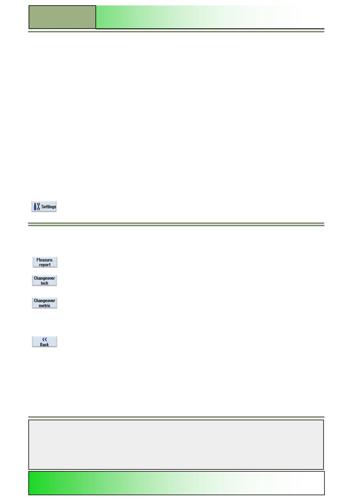
Roughing
Finishing
Direction
Same direction of machining
Alternating direction of machining
X0
Corner point 1 of surface in X direction (abs)
Y0
mm
Corner point 1 of surface in Y direction (abs)
Z0
Height of blank (abs)
X1
Corner point 2 of surface in X (abs or inc)
Y1
mm
Corner point 2 of surface in Y (abs or inc)
Z1
Height of finished part (abs or inc)
Notes
828D/840Dsl SINUMERIK Operate
Page 27
M570
M570
Operating mode “JOG“
Parameters of “Face milling”
Parameter
Unit
Description
DXY
mm
Max. infeed in the XY plane (dependent on milling cutter diameter)
Alternatively you can specify the plane infeed as a %, as a ratio plane infeed
%
(mm) to milling cutter diameter (mm).
DZ
mm
Max. infeed in Z direction (only for roughing)
UZ
mm
Finishing allowance, depth
Setting
Selecting the function “Settings”
You can predefine millimetre or inch as the measuring units for the control unit. The change-over of the measurement
units is done for the whole control. All necessary entries are thereby converted automatically into the new measurement
units, e.g.:
Positional data
Tool corrections
Zero point offsets
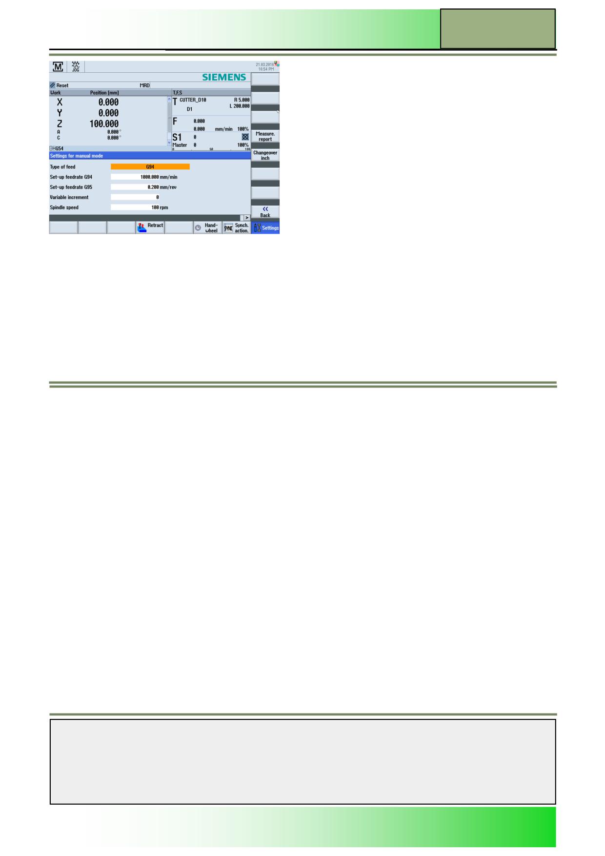
By pressing the HSK 2.8 “Settings” in the extended horizontal softkey bar in operation area
“Machine” under operation mode “JOG” the following input mask will be shown on the screen.
Vertical softkey bar (VSK)
Display area
Description
By pressing the VSK 4 "Measure. report" the settings for the measuring report can be
configured.
By pressing the VSK 5 "Changeover inch" the measuring units are converted from the metric to
the imperial (inch) dimension system. New values have to be entered in inches. By pressing
this key the key function switches to "Changeover metric".
By pressing the VSK 5 "Changeover metric" the measuring units are converted from the imperi-
al (inch) to the metric dimension system. New values have to be metric. By pressing this key
the key function switches to "Changeover inch".
Accept the selection by pressing the VSK 8 “OK” or
cancel by pressing the VSK 7 “Cancel”.
By pressing the VSK 8 "Back" you switch back to the main screen of the Sinumerik Operate
with extended HSK.
Notes
M570
Page 28
828D/840Dsl SINUMERIK Operate
Operating mode “JOG“
M570
Measurement units [metric/imperial]
Country specific settings of the measuring units are not displayed in the input masks. In the following table the measuring
units metric and imperial are compared with one another. A switchover can be made in the "T,S,M," input mask or by press-
ing the HSK 2.8 “Settings” in the extended HSK-bar and VSK 5 “Changeover Inch” or “Changeover Metric” as mentioned
before.
metric
Inch
mm
in
mm/tooth
in/tooth
mm/min
in/min
mm/U
in/U
m/min
ft/min
Notes
828D/840Dsl SINUMERIK Operate
Page 29
M570

M570
Operating mode “JOG“
Parameter setting for manual operation
In the “Settings for manual mode“ window all configurations for manual operation can be done.
Parameter
Unit
Meaning
Type of feedrate:
G94
[mm/min]
Axis feedrate/linear feedrate
[mm/rev]
Revolutional feedrate
G95
Setup feedrate:
G94
[mm/min]
Axis feedrate/linear feedrate
[mm/rev]
Revolutional feedrate
G95
Variable increment
Enter the desired increment for axis traversal by variable increments
Spindle speed
[rpm]
Spindle speed in revolutions per minute
After inserting the values in the input fields, press the VSK 8 “Back“ to switch back to the main screen of the Sinumerik Op-
erate in the extended view.
M570: END
Notes
M570
Page 30
828D/840Dsl SINUMERIK Operate
M571
Operating mode “MDA”
Sinumerik
Operate
Module Description:
This module describes how a program can be loaded directly from the program manager into the
MDA-buffer and how the processing of the program is started.
It will be explained how an edited program, created in the working window, is written from the MDA-
buffer to any directory on the control unit.
You learn how to create a directory and a workpiece file of the type *.WPD.
Module Objective:
In this module you learn the different options of the operating mode “MDA” in the operat-
ing area “Machine“.
Content:
Operating mode “MDA“
“Load MDI“
“Save MDI“
This document was produced for training purposes.
828D/840Dsl SINUMERIK Operate v4.7
Page 1
M571
Siemens assumes no responsibility for its contents.
M571
M571
Page 2
828D/840Dsl SINUMERIK Operate

Operating mode “MDA”
M571
Operating mode
"MDA":
START
Operating
mode “MDA“
“Load MDI“
“Save MDI“
Operating mode
"MDA":
END
Notes
828D/840Dsl SINUMERIK Operate
Page 3
M571
M571
Operating mode “MDA”
Operating mode “MDA“
In "MDA" mode (Manual Data Automatic), you can enter G-code commands block-by-block and immediately execute them
for setting up the machine.
You can load an MDA program straight from the Program Manager into the MDA buffer. You may also store programs
which were rendered or changed in the MDA operating window into any directory of the program manager.
Selecting the operating mode “MDA“
The operating mode “MDA“ can be selected as follows:
Press the “MDA” key on the operator panel (OP).
The operating mode “MDA“ will be opened
immediately.
- OR -
Press the “MENU SELECT” key on the operator panel.
Press the VSK 2 “MDA“ in the yellow vertical softkey bar on the right side of the screen and the
operating mode “MDA” will be opened immediately.
Now switch to the operating area “Machine” by pressing the “MACHINE” key on the operator
panel or on the keyboard or press the “MENU SELECT“ key on the operator panel and the
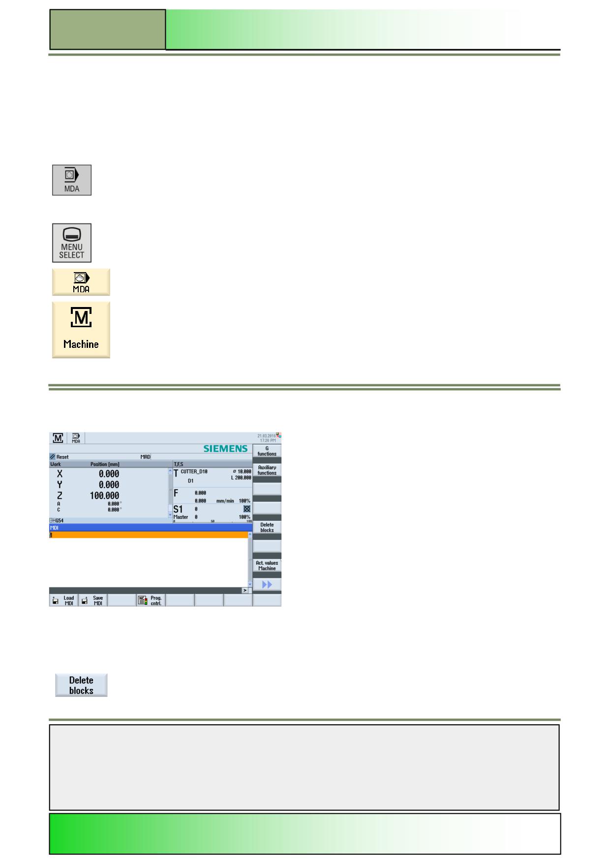
yellow HSK 1 “Machine“. The following screen opens:
In the operating mode “MDA“ the following softkeys are shown in the horizontal and vertical softkey bar of the Sinumerik
Operate:
Vertical softkey bar
Display area
Description
By pressing the VSK 1.5 “Delete blocks” entered program blocks can be deleted.
Notes
M571
Page 4
828D/840Dsl SINUMERIK Operate
Operating mode “MDA”
M571
Horizontal softkey bar 1
Display area
Description
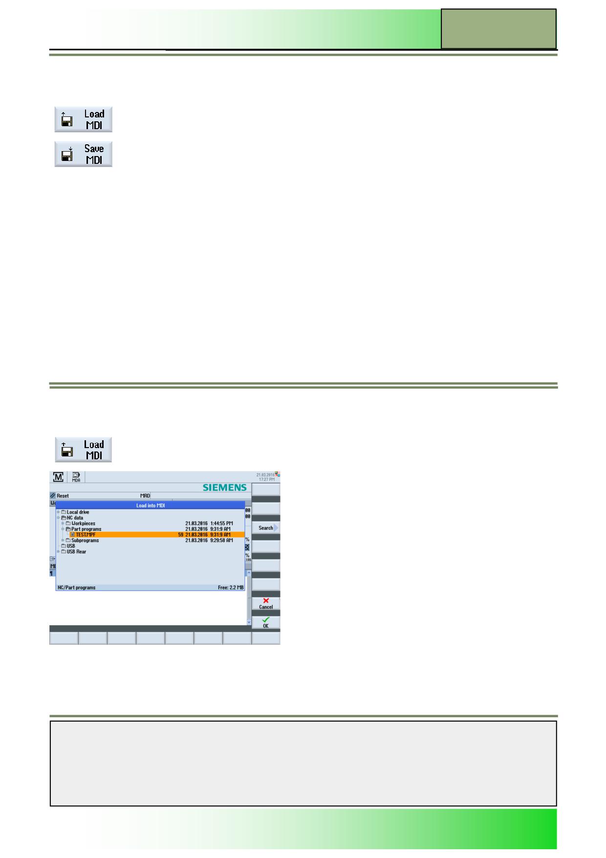
By pressing the HSK 1 “Load MDI” the “Load into MDI” with the program manager window
opens.
By pressing the HSK 2 “Save MDI” the “Save from MDI : Select storage location” with the
program manager window opens.
“Load MDI“
Selecting the function “Load MDI”
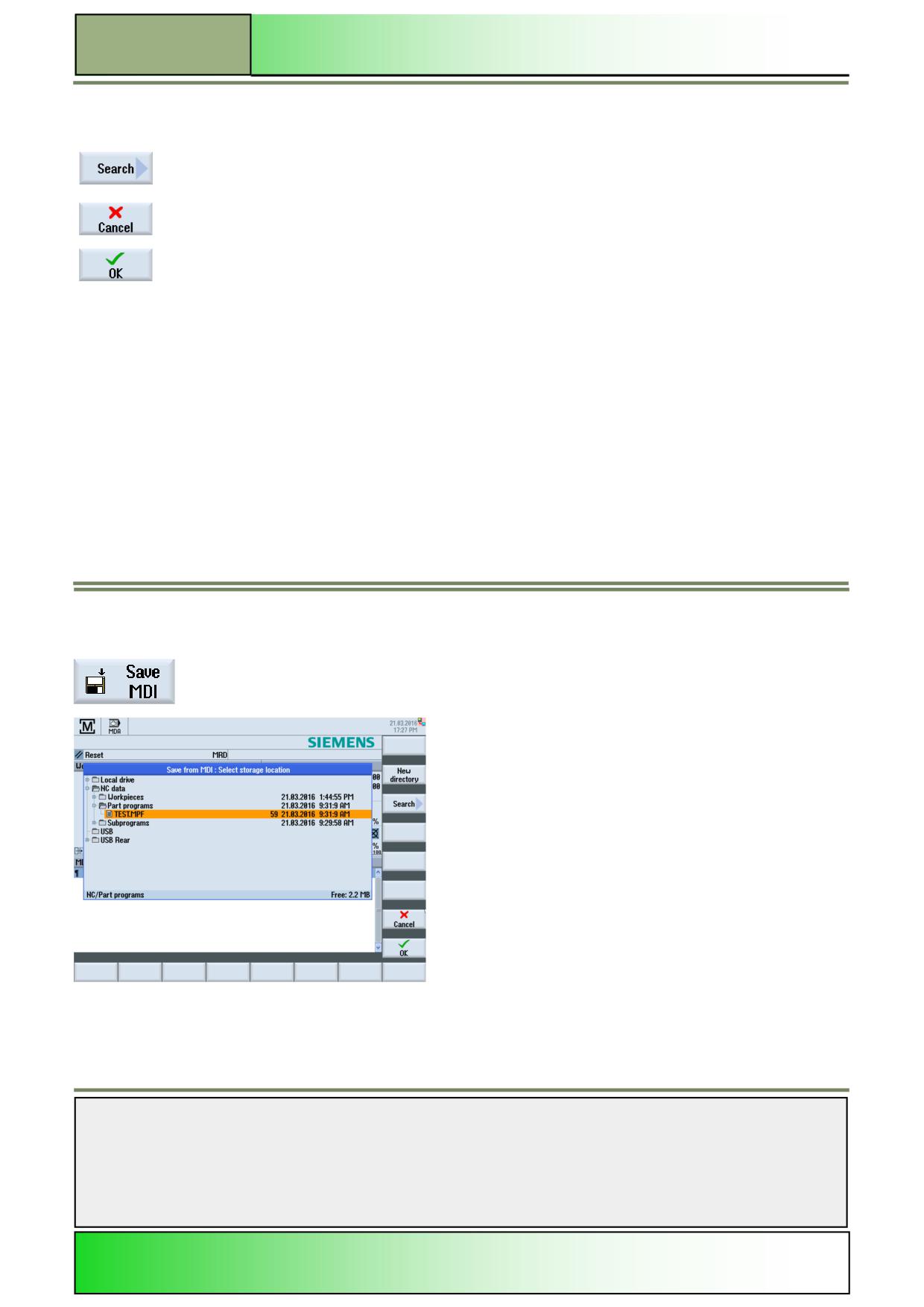
By pressing the HSK1 “Load MDI” the “Load into MDI” window with the Program Manger is
displayed as below:
To navigate in the program manager window use the blue cursor-keys
The following operation options are available in the vertical softkey bar to the right:
Notes
828D/840Dsl SINUMERIK Operate
Page 5
M571
M571
Operating mode “MDA”
Vertical softkey bar
Display area
Description
Press the VSK 3 “Search“ to open the “Find file” window.
Press the VSK 7 “Cancel“ to close the “Load into MDI” window.
By pressing the VSK 8 “OK” the marked program will be opened after closing the window
“Load into MDI” and taken over in the MDI-window.
If a program is already in the MDI-buffer, you will be asked to overwrite. Accept with “OK” or
refuse with “Cancel”. A program loaded in the MDI-buffer can be edited or can be executed by
pressing the “CYCLE START“-button on the MCP
Loading a MDI-program
1.
Switch to operating mode “MDA“.
2.
Press the VSK 1 “Load MDA”.
The “Load into MDI” Program manger window opens.
3.
Mark the program you want to load with the orange cursor-keys.
4
Press the VSK 8 “OK“.
The window closes and the program is ready for machining.
“Save MDI“
Selecting the function “Save MDI”
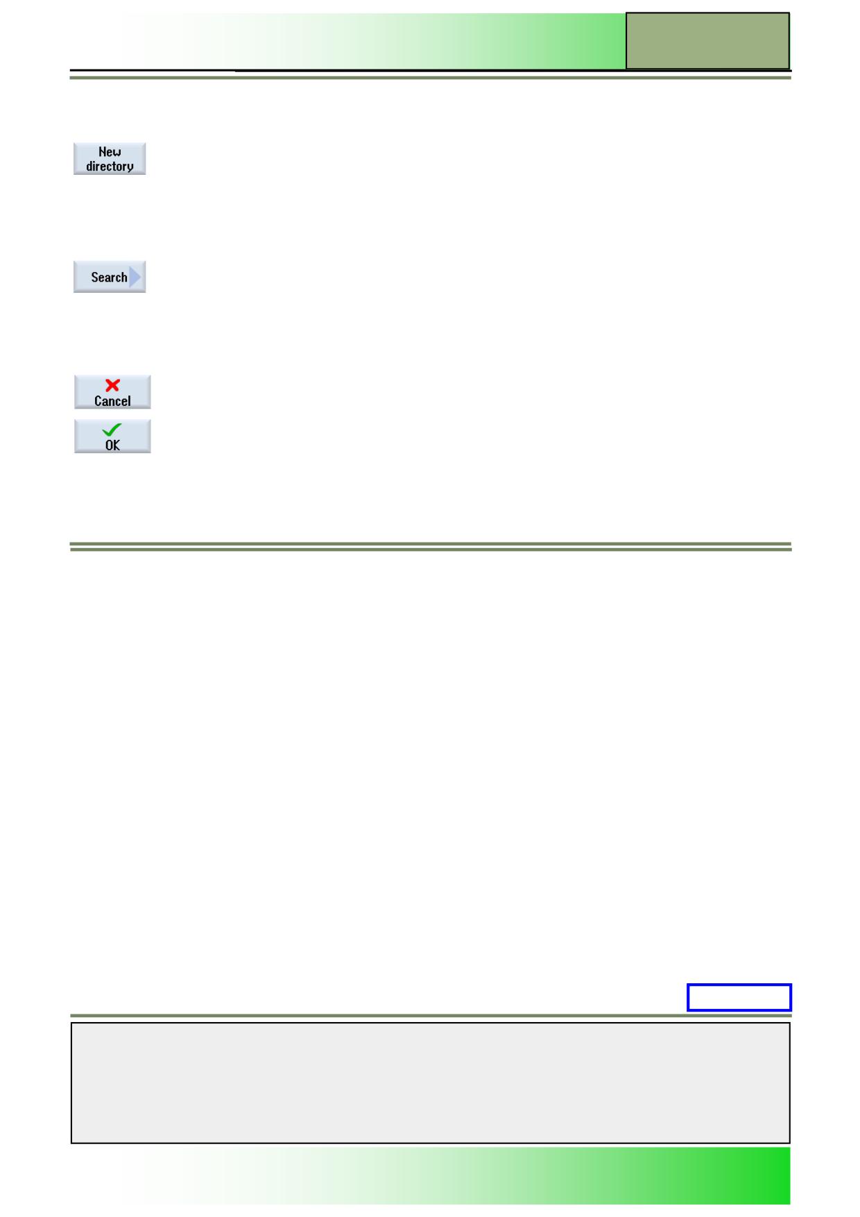
By pressing the HSK2 “Save MDI” the “Save from MDI : Select storage location” window with
the Program Manger is displayed as below:
Navigate through the program manager window by means of the blue cursor-keys.
The following softkeys are available in the vertical softkey bar.
Notes
M571
Page 6
828D/840Dsl SINUMERIK Operate
Operating mode “MDA”
M571
Vertical softkey bar
Display area
Description
By pressing the VSK 1 “New directory“ a new directory can be created in the “Local drive”
folder.
An input window opens where a name can be entered for the new directory that is to be created.
Create a new directory by pressing the VSK 8 “OK” or abort with pressing the VSK 7 “Cancel”.
The “New directory” softkey is not active if you have placed the cursor on or in the “NC data”
directory.
Press the VSK 3 “Search“ to open the “Find file” window.
Display area
Description
By pressing the VSK 7 “Cancel” the “Save from MDI” window will be closed without saving.
By pressing the VSK 8 “OK”, with the cursor on a folder, the “New G code program” window
opens. Select the file type (Main program: MPF/Subprogram: SPF) that you wish to create.
After input of the filename the program will be written from the MDI-buffer to the new created
file or the file that is marked with the cursor.
Saving a MDI-program
1.
Select the operating mode “MDA”.
The “MDI” editor opens.
2.
Create the MDI program by entering the G-code commands using the keyboard.
3.
Press the VSK 2 "Save MDI”.
The "Save from MDA : Select storage location" window opens. It shows you a view of the program
manager.
4.
Select the drive to which you want to save the MDI program you have created, and place the cursor on
the directory in which the program is to be stored.
5.
Press the VSK 8 “OK“.
Note:
When you place the cursor on a folder, a window opens which prompts you to assign a program name.
When you place the cursor on a program, you are asked whether the file should be overwritten or not.
7.
Enter a name for the program and press the VSK 8 “OK“.
The program will be saved under the specified name in the selected
directory.
M571: END
Notes
828D/840Dsl SINUMERIK Operate
Page 7
M571

M571
Operating mode “MDA”
Notes
M571
Page 8
828D/840Dsl SINUMERIK Operate
M573
Operating area “Parameter”
Sinumerik
Operate
Module Description:
In the tool management area all tool data relevant for machining (e.g., tool length, radius correction,
tool wear and magazine configuration) can be viewed and modified.
The tool management contains the following sub-functions:
the tool list
the tool wear
the magazine management
In addition to these sub-functions a machine specific list can be configured by the machine manufac-
turer. Refer to the machine manufacturers documentation.
In the "Work offset" menu the linear and rotational offsets can be viewed and modified in the settable
work offset (WO).
Module Objective:
In this module you learn to use the tool management with the Sinumerik Operate. You
learn about the programming philosophy of the adjustable and programmable work off-
set, the function of the user variables and how to modify the “working area limitation”.
Content:
Operating area “Parameter“
Tool list
Tool wear
Magazine management
Zero offset basics
Work offset
This document was produced for training purposes.
828D/840Dsl SINUMERIK Operate v4.7
Page 1
M573
Siemens assumes no responsibility for its contents.
M573
M573
Page 2
828D/840Dsl SINUMERIK Operate

Operating area “Parameter”
M573
Operating area
"Parameter":
START
Operating
area
“Parameter“
Tool list
Tool wear
Magazine
management
Zero offset
basics
Work offset
Operating area
"Parameter":
END
Notes
828D/840Dsl SINUMERIK Operate
Page 3
M573
M573
Operating area “Parameter”
Operating area “Parameter“
Selecting the operating area “Parameter”
In the Operation area “Parameter” you have a choice of selecting between various lists (e.g. Tool list, tool wear, magazine
list, offsets, user variables and setting data). For example in the tool management area, all tools and if configured also the
magazine locations are being displayed. Both lists display the same tools in the same order. When switching between lists,
the position of the cursor on a particular tool in the current screen is carried over to the same tool in a new screen. The lists
differ from each other by the displayed parameters and the Softkey functions.
Switching between lists is a specific change from one topic to the next.
Tool list: All parameters and functions required to create and set up tools are displayed.
Tool wear: All parameters and functions that are required during operation, e.g. wear and monitoring functions, are
listed here.
Magazine: Magazine and magazine location-related parameters and functions for the tools and magazine locations are
listed here.
The operating area “Parameter“ can be opened from every operating modes (“JOG”, “MDA”, “AUTO”).
Press the “OFFSET”-key on the keyboard.
The operating area “Parameter“ respectively the “Tool list” opens directly.
- OR -
Press the “MENU SELECT“-key on the operator panel. The yellow horizontal and vertical soft-
key bar opens.
Then switch to the operating area “Parameter” by pressing the HSK 2 “Parameter” on the oper-
ator panel.
The operating area “Parameter” opens, with the “Tool list”, “Tool wear”, “Magazine”, “Work
offset”, “User variables” and the “Setting data”.
These functions are made available in the following described horizontal softkey bar.
Horizontal softkey bar (HSK)
Display area
Description
By pressing the HSK 1 “Tool list” the tool list window opens.
See section 3 “Tool list”.
By pressing the HSK 2 “Tool wear“ the tool wear list opens.
See section 4 “Tool wear”.
Notes
M573
Page 4
828D/840Dsl SINUMERIK Operate
Operating area “Parameter”
M573
Display area
Description (continuation)
By pressing the HSK 4 “Magazine“ the Magazine management is opened.
By pressing the HSK 5 “Work offset“ a list with all Work offsets is opened.
By pressing the HSK 6 “User variable“ a list with all R variables is opened.
By pressing the HSK 8 “Setting data” a list with all setting data is opened.
By pressing the "Extend"-button on the operator panel (OP) more softkeys on the HSK are
available.
By pressing the HSK 2.6 “CTRL Energy“ the SINUMERIK Ctrl-Energy analysis screen is
opened.
Tool List
Selecting the “Tool list”
By pressing the HSK 1 “Tool list“ the “Tool list“ window opens.
(Note the screen below.)
In the tool list all parameters and functions that are required to create and set up the tools are displayed, regardless weather
the tools are assigned or not assigned to a magazine location. Each tool is uniquely identified by the location number, the
tool name and the replacement tool number.
The most common tools and probes for turning, drilling and milling are offered in the tool list.
Geometrical and technological tool data can be assigned to each tool type.
Depending on the tool type different correction data are necessary.
Notes
828D/840Dsl SINUMERIK Operate
Page 5
M573
M573
Operating area “Parameter”
Vertical softkey bar
Display area
Description
By pressing the VSK 1.1 “Tool measure” the “Measuring tool” window opens.
By pressing the VSK 1.2 “New tool” a new tool can be created. This function is only availa-
ble, if the cursor is positioned on a filed that does not yet has a tool assigned to it.
By pressing the VSK 1.3 “Edges” the vertical softkey bar for assigning new cutting edges and
deleting existing cutting edges opens to the right side of the screen. If a tool has several cut-
ting edges each edge gets its own set of correction data.
By pressing the VSK 1.4 “Further data” more information about a tool will be displayed. This
function is only available for tools which have additional information.
By pressing the VSKs 1.5 ”Unload” or “Load” the actual selected tool wil be unloaded from or
loaded to the magazine. Unloaded tools are being displayed on the bottom of the magazine
list.
By pressing the VSK 1.6 “Delete tool” the selected tool will be deleted from the tool list.
By pressing the VSK 1.7 “Magazine selection” Softkey multiple times you can jump between
buffer location (spindle and gripper), Magazine and NC-memory (unloaded tools) and back to
the buffer location. The cursor is always positioned at the beginning of each group.
By pressing the VSK 1.8 “Extend” on the operator panel the extended vertical softkey bar 2
opens on the right hand side of the screen.
By pressing the VSK 2.1 “Sort” you can sort the tools in the tool list according to the following
criteria:
Magazine
Name
Type
T-Number
The suitable softkeys are offered in the vertical softkey bar.
Pressing the VSK 2.2 “Filter” opens the screen to set the filter options.
Pressing the VSK 2.3 “Search“ opens a new softkey bar with the functions
Tool
Magazine location
Empty location
The type of search is selected by the sotfkey selection.
Pressing the VSK 2.4 „Details“ opens a new softkey bar with the functions
Tool Data
Cutting edge data
Monitoring data
The details of the tool which is selected by the cursor position are listed in the screen.
Pressing the VSK 2.8 “Back“ on the operator panel you switch back to the vertical softkey bar
1.
Notes
M573
Page 6
828D/840Dsl SINUMERIK Operate
Operating area “Parameter”
M573
Tool parameters
Column header
Meaning
Loc.
Magazine/location number
Spindle location as an icon
Location for gripper 1 and 2 as icons:
(Applies only when a spindle with dual gripper is used.)
Magazine number:
If more than one magazine is available, first the location number and then the magazine num-
ber is displayed separated by a slash. E.g.:
Location number 1 in magazine 1
Location number 1 in magazine 2
Tools in the tool list not assigned to a magazine are displayed without a location number at the
end of the window.
You can manage tools that are not changed automatically, by hands (hand tools).
If the orange selection cursor is placed in the type
field on a tool icon you can change the tool type by pressing the “SELECT”-key.
Type
Tool type
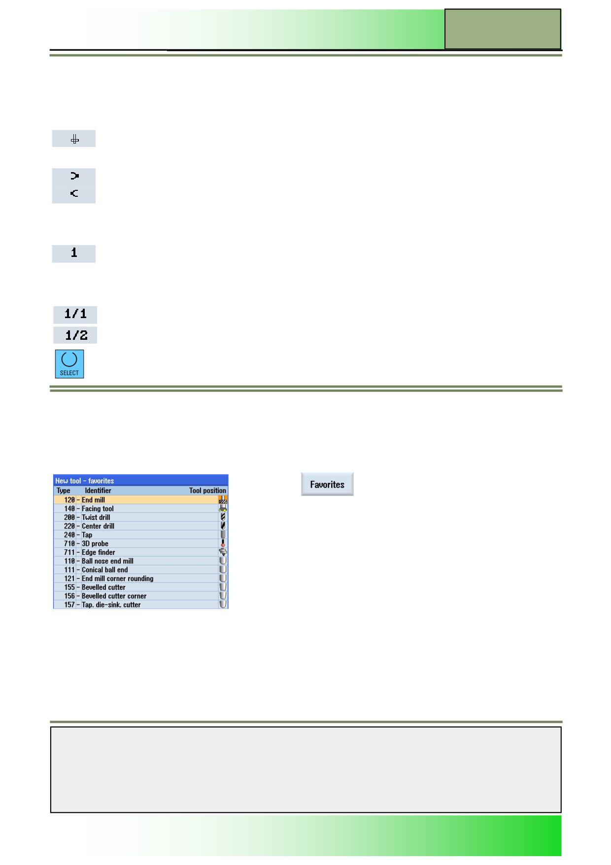
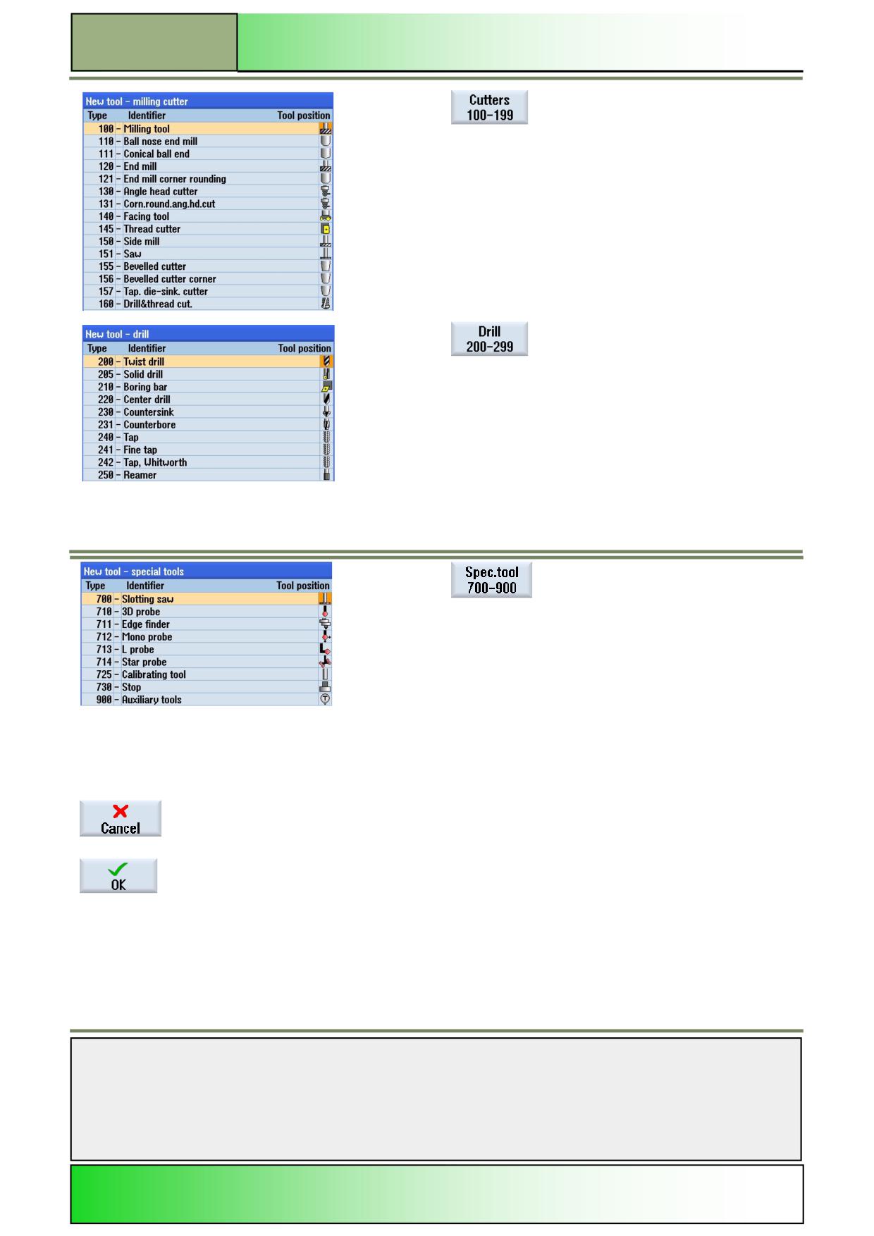
Tools can be created on a free tool position or by pressing the VSK 1.2 “New tool” in the tool list. The following tool win-
dows can be opened by pressing the corresponding vertical softkeys.
Press the VSK 1 “Favourites” to open the “New tool - favour-
ites” list. In the favourite list
the most often used tools are saved as favourites for a fast
access.
Notes
828D/840Dsl SINUMERIK Operate
Page 7
M573
M573
Operating area “Parameter”
Press the VSK 2 “Cutters 100-199” to open the “New tool -
milling cutter” list.
A list of all available milling cutters opens.
Press the VSK 3 “Drill 200-299” to open the “New tool -
drill” list.
A list with all available
Drilling tools opens.
Press the VSK 5 “Spec.tool 700-900” to open the “New
tool - special tools” list.
A list with special tools opens.
Press the VSK 7 “Cancel” to reject the tool selection and to jump back to the “Tool list” window
in the operating area “Parameter”.
Press the VSK 8 “OK“ to accept the selected tool and to jump back to the “Tool list” window in
the operating area “Parameter”.
The selected tool will be loaded into the tool list
Notes
M573
Page 8
828D/840Dsl SINUMERIK Operate

Operating area “Parameter”
M573
Column header
Meaning (continuation)
Tool name
Name of the tool:
To identify a tool you can enter a tool name as text
or a T-number. If a new tool is created, tool names are pre-assigned as default.
ST
Replacement tool number:
(for replacement tool strategy) As default “1” is being entered here. If a new tool with the same
name, as a already existing tool, is being created, then the new tool gets the Index “2”. This way
it is possible to define a replacement tool.
D
Cutting edge number:
For tools with multiple cutting edges, each tool receives it’s own correction data field. Up to 9
edges per tool can be managed. The max. Number depends upon the control configuration.
Length
Tool length:
Geometry length of the tool.
Radius/diameter
Tool radius/diameter
For every tool, information about the tool radius or diameter can be entered here.
The changeover from diameter to radius or vice versa can be set via a machine datum.
Tip angle or Pitch
Tip angle for
Type 200 - twist drill
Type 220 - center drill
Type 230 - countersink
Pitch for
Type 240 - tap
N
Number of teeth for:
Type 100 - milling tool
Type 110 - ball nose cylindrical die sinking cutter
Type 111 - ball nose tapered die-sinking cutter
Type 120 - end mill
Type 121 - end mill with corner rounding
Type 130 - angle head cutter
Type 140 - facing tool
Type 150 - side mill
Type 155 - bevelled cutter
Type 156 - bevelled cutter with corner rounding
Type 157 - tapered die-sinking cutter
Type 160 - drill and thread cutter
Notes
828D/840Dsl SINUMERIK Operate
Page 9
M573
M573
Operating area “Parameter”
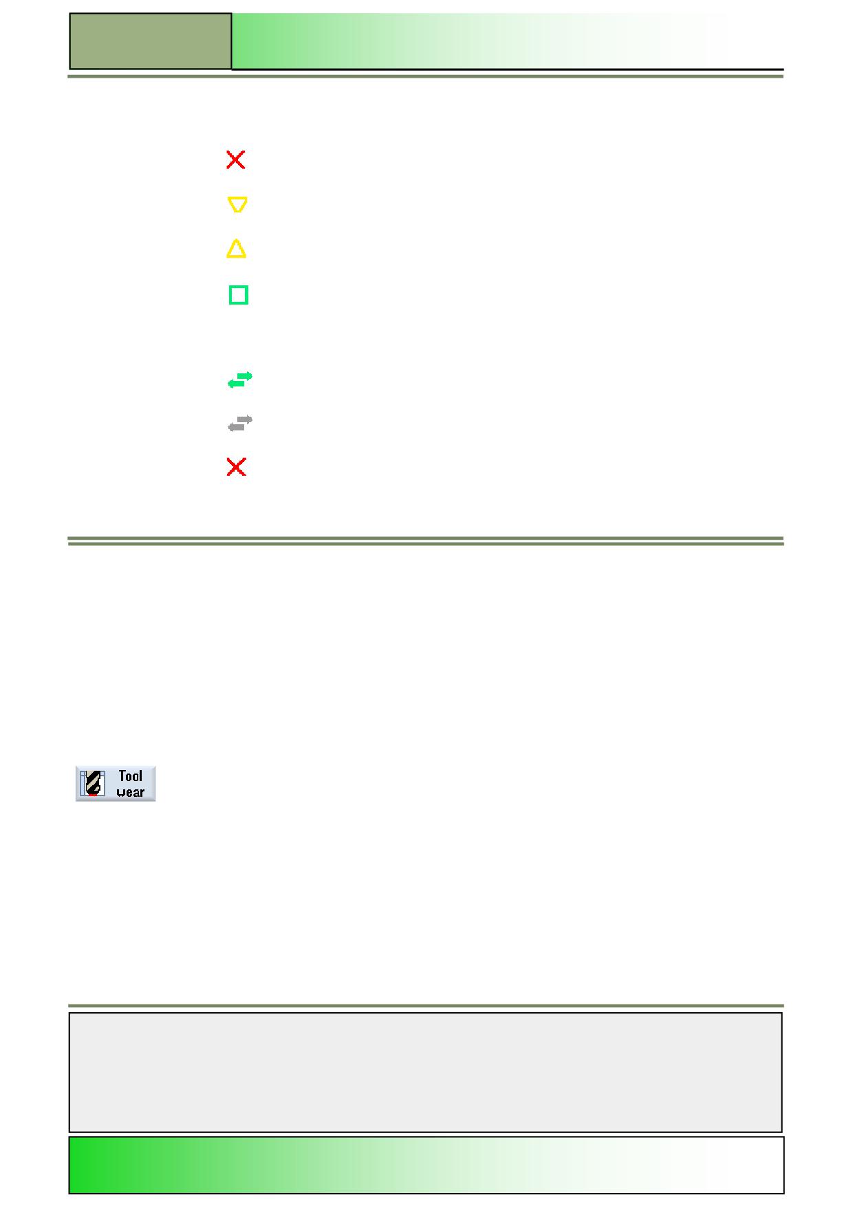
Icons in the toolbar and their meaning
Icons
Meaning
Red X
The tool is disabled
Yellow triangle pointing
The pre-warning limit has been reached
downward
Yellow triangle pointing
The tool is in a special state
upward
Place the cursor on the marked tool. A tool tip will provide a brief description
Green frame
The tool is preselected.
Magazine/location number:
Green double arrow
The magazine location is positioned at the change position
Gray double arrow
The magazine location is positioned at the loading position
Red X
The magazine location is disabled
Tool wear
Selecting the function “Tool wear“
All parameters and functions that are required during operation are contained in the tool wear list.
Tools that are in use for long periods are subject to wear. You can measure this wear and enter it in the tool wear list. The
Sinumerik Operate then takes this information into account when calculating the tool length or radius compensation.
This ensures a consistent level of accuracy during workpiece machining.
You can automatically monitor the tools' working times via the workpiece count, tool life or wear.
In addition, you can disable tools when you no longer wish to use them.
Note: Depending on the control configuration, the input of the tool wear can be additive. Please refer to the machine tool
manufacturer documentation.
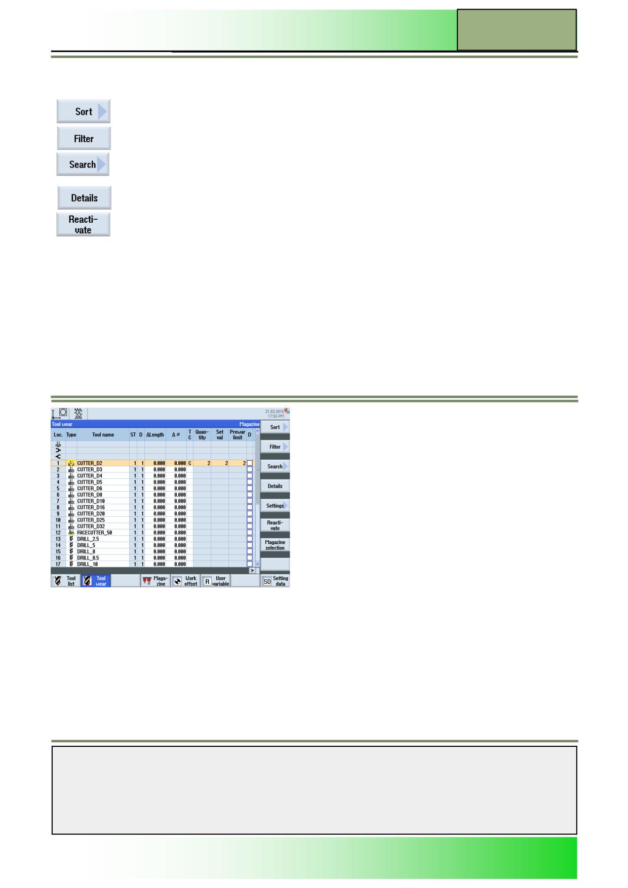
By pressing the HSK 2 “Tool wear“ the “Tool wear” screen input mask opens.
Notes
M573
Page 10
828D/840Dsl SINUMERIK Operate
Operating area “Parameter”
M573
Vertical softkey bar
Display area
Description
By pressing the VSK 1 “Sort” and “Filter” you can sort and filter the tools in the tool list ac-
cording to different parameters.
By pressing the VSK 1 “Search” and “Details” you can search and view the tool details in the
tool list according to different parameters.
By pressing the VSK 6 “Reactivate“ locked tools, and tools that have reached their pre-
warning limit can be made operational again.
Notes
828D/840Dsl SINUMERIK Operate
Page 11
M573

M573
Operating area “Parameter”
Parameters for “Tool wear”
Parameter
Meaning
Location
Magazine/location number:
Type
Tool type:
Tool name
Tool name:
ST
Replacement tool number:
D
Cutting edge number
ΔLength
Length wear
In this field changes for the tool length are entered
ΔRadius
Radius wear
The Sinumerik Operate checks the entered values
whether they exceed an absolute or incremental threshold or not.
The incremental threshold is the maximum difference between present wear and new wear.
The absolute threshold is the maximum total wear value that can be entered.
Note:
Please refer to the machine manufacturer's specifications.
T
Tool monitoring by tool life:
With the tool life T (Time), the service life for tool with machining federate is monitored in
minutes.
C
Tool monitoring by count
With the count C, the number of workpieces machined by the tool is counted.
Tool monitoring by wear
With wear W, the greatest value in the wear parameters ΔLength X, ΔLength Z, ΔRadius or
W*
ΔØ in the wear list is monitored.
* The wear monitoring is configured via a machine data item.
Tool life (T)
Tool life
Quantity (C)
Number of workpieces
Wear (W)
Tool wear
The wear monitoring is configured via a machine data item. Please refer to the machine manu-
facturer`s instructions.
Set val
Setpoint value for tool life, workpiece count, or wear.
Prewar limit
Prewarning limit:
Specification of the tool life, workpiece count or wear at which a warning is displayed.
Note:
If the adjusted rest life of the tool, the number of changes or the wear is reached, the tool will be
disabled.
This tool will not be selected for the next tool change.
If present, an adequate sister tool will be used instead.
The monitoring refers in each case to the selected cutting edge.
It is possible to reactivate a disabled tool.
D
Single tools can also be disabled by hand, if these tools are not in use anymore or if the tools life
ran off.
(The tool is disabled if the checkbox is activated).
Notes
M573
Page 12
828D/840Dsl SINUMERIK Operate

Operating area “Parameter”
M573
Icons in the tool wear list and their meaning
(See section Tool List, Icons in the tool list, in this module)
Entering the tool wear or disabling a tool
1.
Press the “MENU SELECT“-key on the operator panel, then the HSK 2 “Parameter” and the
HSK 2 “Tool wear” to switch to the tool wear list.
2.
Enter values for length, radius, setpoint, prewarning and tool life.
- OR -
2.
Activate the “D”-parameter checkbox for disabling the tool manually.
Sort and Filter
For the functions “Sort” and “Filter” in the tool list refer to the section 3 in this module.
Reactivating a tool
You can replace disabled tools or make them ready for reuse.
Prerequisite is, that the monitoring function must be active and a setpoint is stored.
1.
Press the “MENU SELECT“-key on the operator panel, then the HSK 2 “Parameter” and the
HSK 2 “Tool wear” to switch to the tool wear list.
2.
Position the cursor on the disabled tool which you would like to reuse.
Press the VSK 6 "Reactivate".
The value entered as the setpoint is entered as the new tool life workpiece count.
The disabled tool is active again.
Notes
828D/840Dsl SINUMERIK Operate
Page 13
M573
M573
Operating area “Parameter”
Reactivating and positioning
When the "Reactivate with positioning" function is configured, the selected tool's magazine location will also be positioned at
a loading point.
You can exchange the tool.
Reactivation of all monitoring types
When the "Reactivation of all monitoring types" function is configured, all the monitoring types set in the NC for a tool are
reset during reactivation.
Note:
Refer to the machine manufacturer‘s specifications.
Magazine management
Selecting the function “Magazine“
Tools are displayed with their magazine-related data in the magazine list. Here, you can take specific actions relating to
the magazines and the magazine locations. Individual magazine locations can be location-coded or disabled for existing
tools.
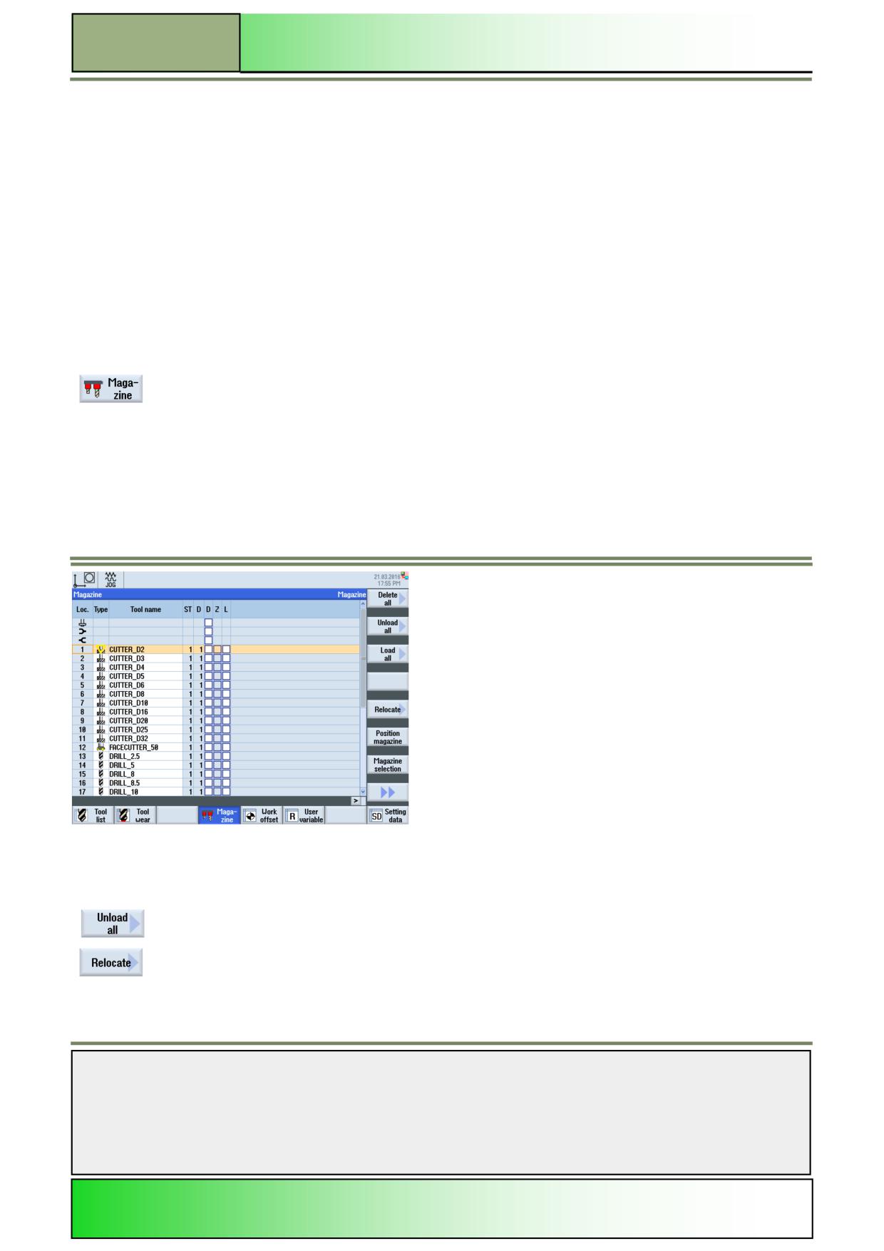
By pressing the HSK 4 “Magazine“ the following magazine list will be displayed on the screen.
In the magazine list, all magazine locations are shown.
It is indicated whether a magazine location is available,
disabled or
occupied by a tool.
If a magazine location is defect, this location can be disa-
bled.
If an oversized tool is inserted, which uses more than a
half of the neighbouring magazine locations, then the
neighbouring magazine locations will be disabled.
Vertical softkey bar
Display area
Description
By pressing the VSK 5 “Unload all“ all tools can be transferred from the magazine location to
the tool libuary, “Unload all“ must be confirmed with the VSK 8 “OK”.
By pressing the VSK 5 “Relocate“ a tool can be transferred from one magazine location to
another or, with pressing the VSK 4 “Spindle”, it can be transferred to the spindle. The select-
ed target location must be confirmed with the VSK 8 “OK” or can aborted with VSK 7
“Cancel”.
Notes
M573
Page 14
828D/840Dsl SINUMERIK Operate

Operating area “Parameter”
M573
Vertical softkey bar continued
Display area
Description
By pressing the VSK 6 “Position magazine“ you can position magazine locations directly on
the loading point.
By pressing the VSK 1.8 “Extend” on the operator panel the extended vertical softkey bar 2
opens with the functions “Sort”, “Filter” and “Details”
(see sections "Tool Wear").
Parameters for “Magazine”
Parameter
Meaning
Loc.
Number of the magazine location:
(Only display, see section “Tool list“)
Type
Tool type:
(Only display, see section “Tool list“)
Tool name
Tool name:
(See section “Tool list“)
ST
Sister tool:
(Only display, see section “Tool list“)
D
Edge number:
(Only display, see section “Tool list“)
D
Magazine location disabled
Z
Oversized tool:
Marking a tool as oversized. The tool occupies two half locations left, two half locations right, one
half location top and one half location bottom in a magazine.
Only tools that are not loaded yet can be marked as oversized.
L
Fixed location coding.
The tool is fixed to the magazine location.
Sorting and filtering tools
When you are working with many tools, with large magazines or several magazines, it is useful to display the tools sorted
according to different criteria. Then you will be able to find a specific tool more easily in the lists.
Zero offset basics
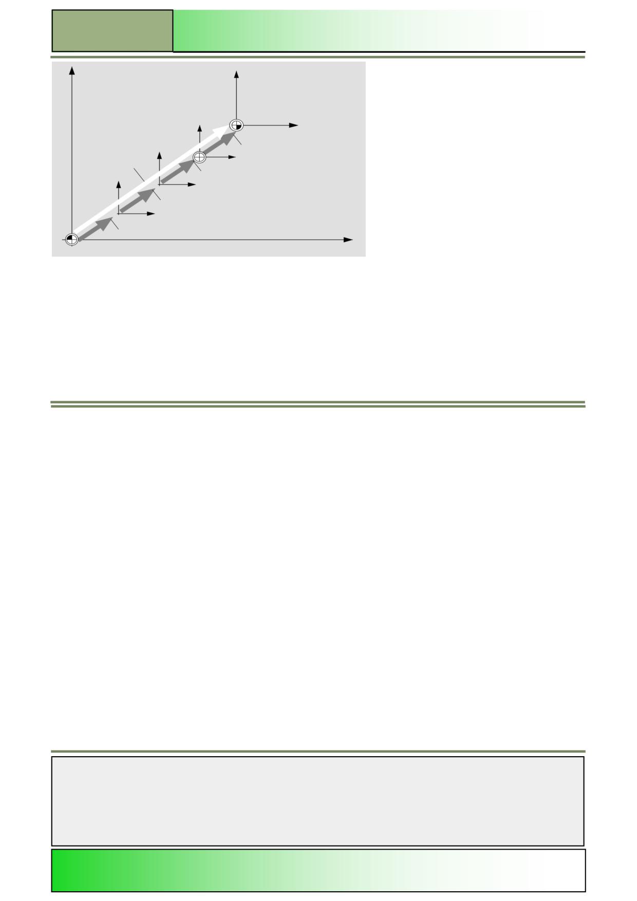
Following reference point approach, the actual value display for the axis coordinates is based on the machine zero (M) of
the machine coordinate system (MCS ). The program for machining the workpiece, however, is based on the workpiece
zero (W) of the workpiece coordinate system (WCS ).
The machine zero and workpiece zero are not necessarily identical.
The distance between the machine zero and workpiece vary in
accordance with the type of tool and the way it is clamped. This zero offset is taken into account during execution of the
program and can be a combination of different offsets.
On the Sinumerik Operate, the position actual value display refers to the SZS-coordinate system (settable zero system).
The position of the active tool relative to the workpiece zero is displayed. The offsets are added as follows:
Notes
828D/840Dsl SINUMERIK Operate
Page 15
M573
M573
Operating area “Parameter”
W
WCS
Transformation of coordi-
Tool offset
SZS
Work offset fine
Work offset coarse
Base offset
MCS
M
Base offset
The base offset is a zero offset that is always active. If you have not defined a base offset, its
value will be zero. You determine the base offset via "Measure workpiece zero” .
See Module B570 - ”Operating mode JOG”, in Sinumerik Operate section “Set Work offset” and
“Measure workpiece zero”.
Every zero offset (G54 to G57, G505 to G599) consists of a coarse offset and a fine offset. You
Zero offsets
can call the work offsets from any sequence program (coarse and fine offsets are added to-
gether).
You can save the workpiece zero, for example, in the coarse offset,
and then store the offset that occurs when a new workpiece is clamped between the old and
the new workpiece zero in the fine offset.
Fine offsets must be set up by the machine manufacturer.
Note:
Also refer to the machine manufacturer's instructions.
You always program coordinate transformations for a specific sequence program.
Coordinate
They are defined by:
transformations:
Offset
Rotation
Scaling
Mirroring
These transformations can work as “new” or they can work “additive” to the active zero point
offset.
Total offset:
The total offset is calculated from the sum of all offsets and coordinate transformations.
Notes
M573
Page 16
828D/840Dsl SINUMERIK Operate
Operating area “Parameter”
M573
Work offset
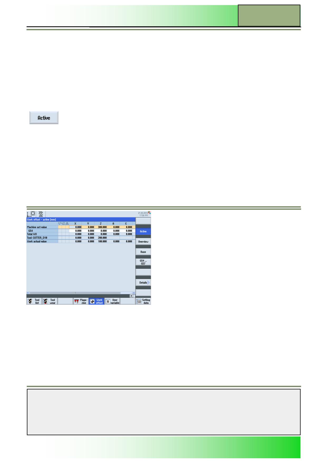
Active work offset
The following work offsets are displayed in the “Work offset - active” window:
Work offsets, for which offsets are included, or for which values are entered
Adjustable work offsets
Total work offset
This window is generally used only for monitoring. The availability of the offsets depends on the setting. Please refer to the
manufacturer's documentation.
Selecting the function “Active”
By pressing the VSK 2 “Active“ the “Work offset - active” window opens.
Work offset overview
In the “Work offset - Overview” window, all active offsets and system offsets are displayed for all set-up axes.
In addition to the offset, the rotation, scaling and mirroring defined using this are also displayed.
This window is generally used for monitoring.
Notes
828D/840Dsl SINUMERIK Operate
Page 17
M573
M573
Operating area “Parameter”
Settable zero offset
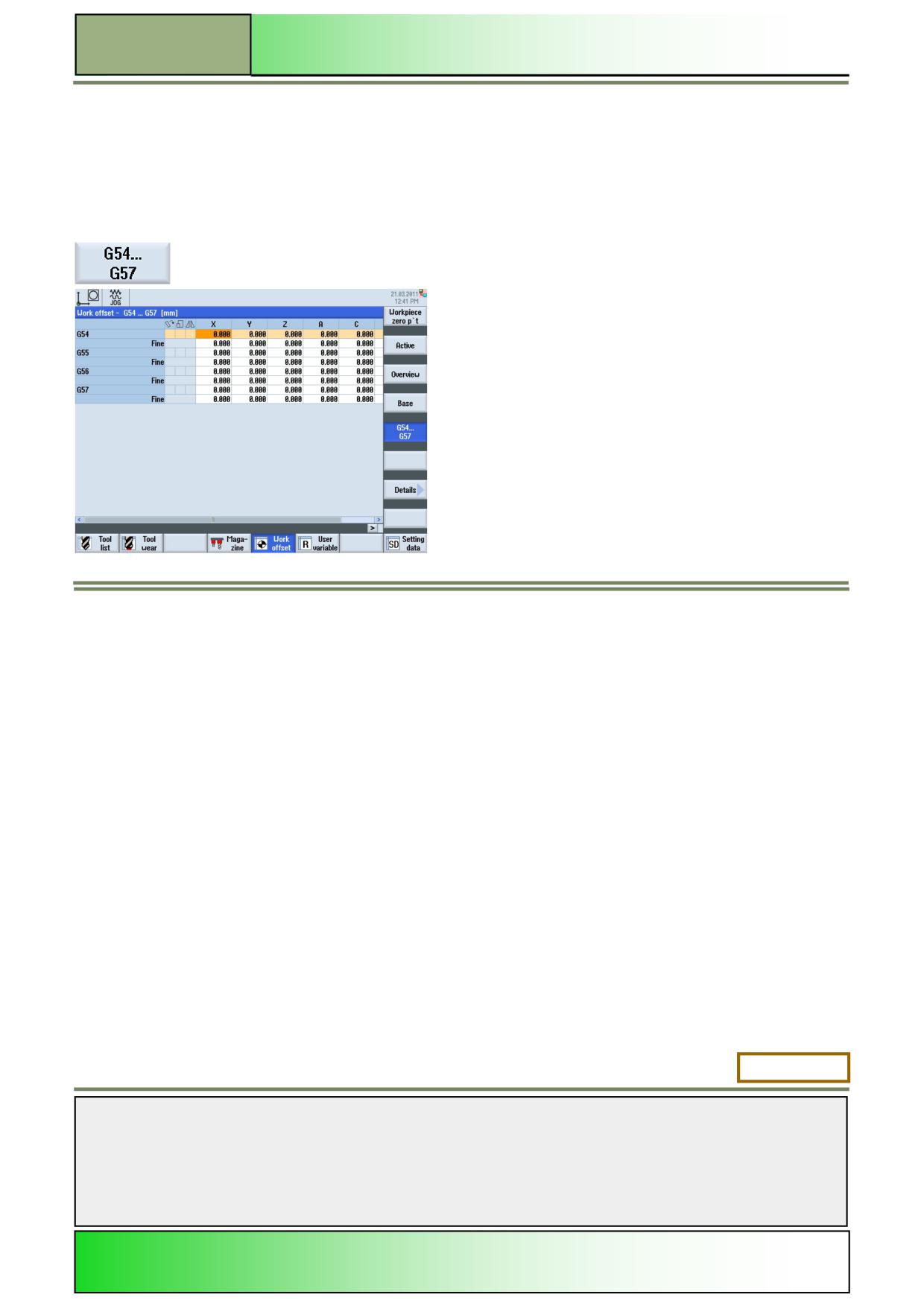
All settable offsets, divided into coarse and fine offsets, are displayed in the "Work offset - G54...G57" window.
Rotation, scaling and mirroring are displayed.
Selecting the function “Work offset - G54...G57”
By pressing VSK 4 “G54...G57“ the following window opens.
Displaying and editing settable zero offset
1.
Press the “MENU SELECT“-key on the operator panel, then the HSK 2 “Parameter” to open the
operating area “Parameter”. Alternatively press the “OFFSET”-key on the keyboard.
2.
Press the HSK 5 “Work offset“.
3.
Press the VSK 4 “G54…G57“.
The “Work offset - G54...G57” window opens.
4.
Values can be edited directly in the table.
Note:
The settable work offsets must first be selected in the program before they have an impact.
M573: END
Notes
M573
Page 18
828D/840Dsl SINUMERIK Operate
M575
Operating area “Program manager“
Sinumerik
Operate
Module Description:
All NC-Programs, which are created with the Sinumerik Operate, are stored in the NC-work memory.
These programs can be accessed via the program manager for:
execution
alteration
copying
renaming
deletion
The SINUMERIK Operate provides the following means of data transmission of NC-programs to oth-
er storage media depending on the system components:
NC memory
Local drive memory
Its own hard disk (PCU 50.x)
Network connection
USB-storage (stick or drive)
Module Objective:
In this module you learn to handle programs and files in the program manager of the Su-
merik Operate.
Content:
Selection and function of the program manager
Storage medium “NC”
Storage medium “Local drive”
Storage medium “USB” drive
This document was produced for training purposes.
828D/840Dsl SINUMERIK Operate v4.7
Page 1
M575
Siemens assumes no responsibility for its contents.
M575
M575
Page 2
828D/840Dsl SINUMERIK Operate
Operating area “Program manager“
M575
Operating area
“Program
manager“:
START
Selection and
function of
the program
manager
Storage
medium “NC
Storage
medium
“Local drive”
Storage
medium
“USB” drive
Operating area
“Program
manager“:
END
Notes
828D/840Dsl SINUMERIK Operate
Page 3
M575
M575
Operating area “Program manager“
Selection and function of the program manager
Selecting the function „Program manager“
The program manager can be selected as follows:
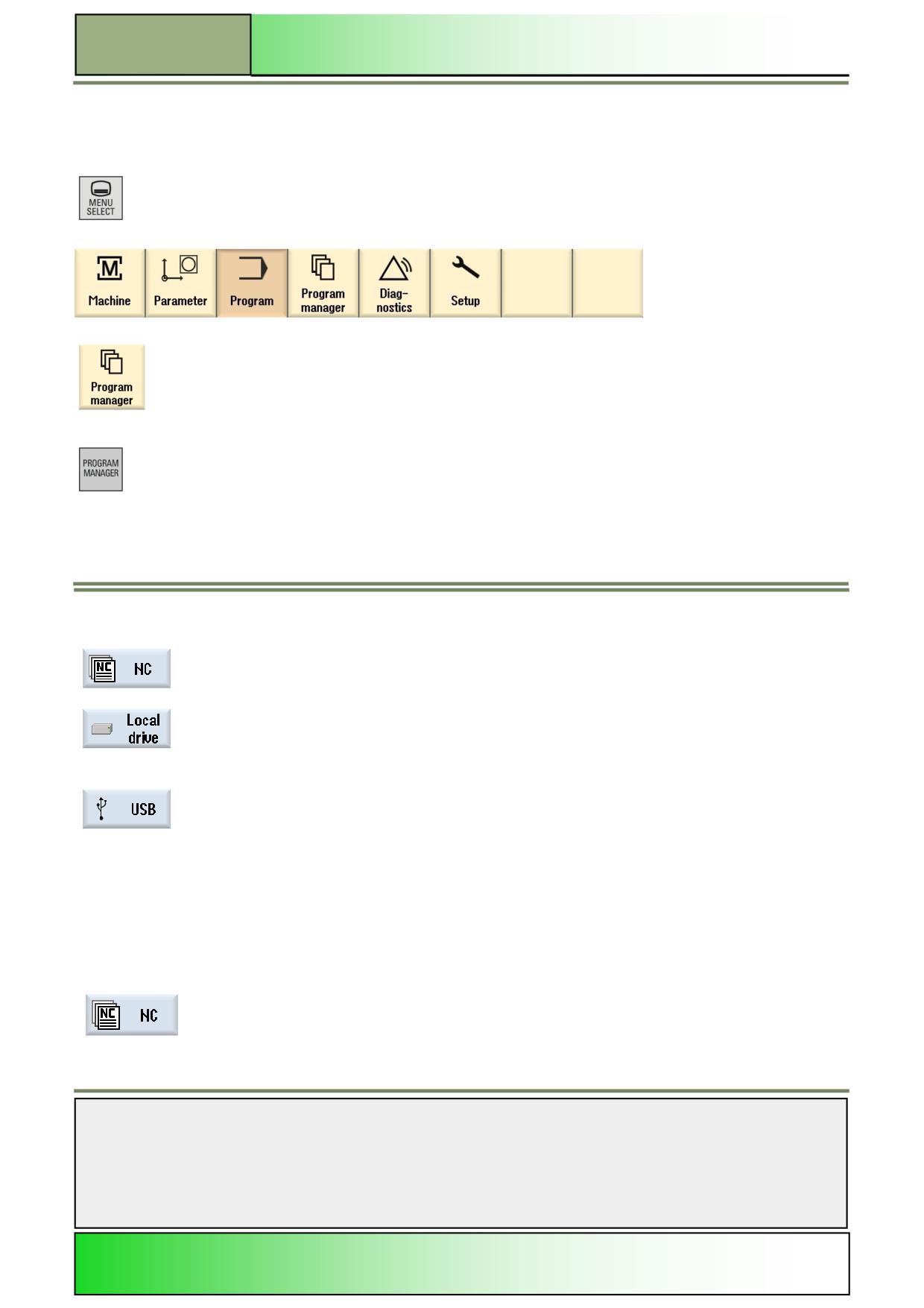
Press the “MENU SELECT”-key on the operator panel.
The following horizontal softkey bar of HMI sl will be displayed:
Press the HSK 4 “Program manager“ to open the program manager window.
- OR -
Press the “PROGRAM MANAGER“-key on the CNC-keyboard to open the program manager
window directly.
The following functions and softkeys will be available in the horizontal softkey bar of the Sinumerik Operate.
Horizontal softkey bar
Display area
Description
By pressing the HSK 1 “NC“ all directories, folders and files of the NC/Hard disc will be dis-
played in a directory tree view in the program manager window.
By pressing the HSK 2 “Local drive” all programs and directories on an allocated network
drive or on an allocated user memory on a CF-Card at the NCU will be displayed. Prerequi-
site for this function is that the "Additional 256 MB HMI user memory on CF card of NCU"
option is activated. For larger CF-cards also more than 256 MB memory can be enabled.
By pressing the HSK 3 “USB“ all programs and directories on an USB drive will be displayed
in a directory tree view in the program manager window. Programs created on an external PC
can be copied to an USB drive and transferred to the NC via the USB interface where they
can be processed further. Direct processing from the USB flash drive is not recommended.
The text on the Softkey e.g “USB” can also be replaced by a drive letter e.g. “G”.
Note: Refer to the documentation of the machine manufacturer.
Storage medium “NC
Selecting the function „NC“
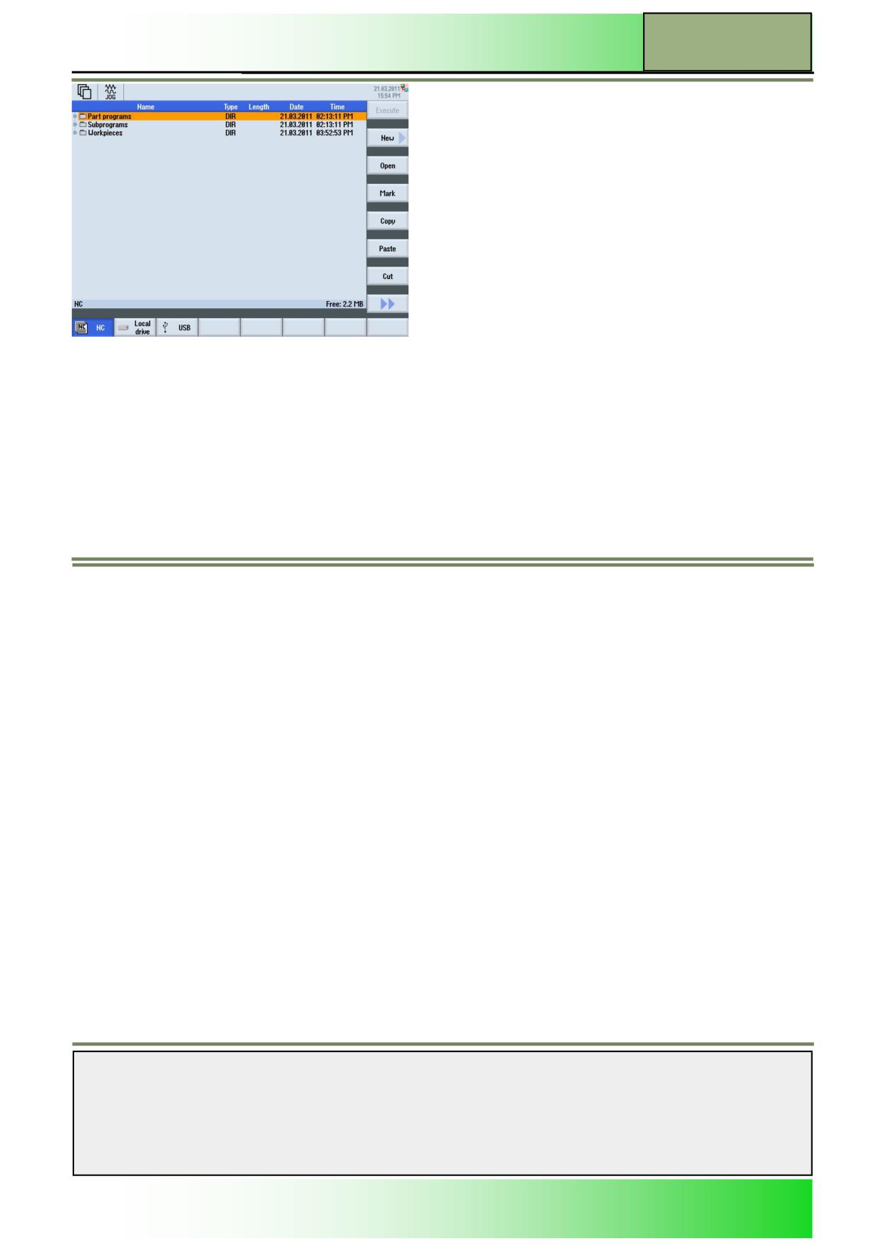
By pressing the HSK 1 “NC“ the program manager opens .
Notes
M575
Page 4
828D/840Dsl SINUMERIK Operate
Operating area “Program manager“
M575
The complete NC-memory is displayed along with all workpieces, the main programs and subroutines.
The directories and programs are listed with the following information:
Name
The name can contain up to 28 characters (24 characters for the name + dot + 3-character extension, e.g. MPF). Per-
missible characters include all upper-case letters (without accents), numbers, and underscores.
Type
*.WPD
Directory
(Workpiece Directory)
Directory/
*.MPF
Program
(Main program File)
Programs
*.SPF
Subprogram
(Subprogram File)
Size
The size of files of the selected directory is displayed in byte.
Date/Time
Date and time of file creation or last change
Notes
828D/840Dsl SINUMERIK Operate
Page 5
M575
M575
Operating area “Program manager“
Vertical softkey bar 1
Display area
Description
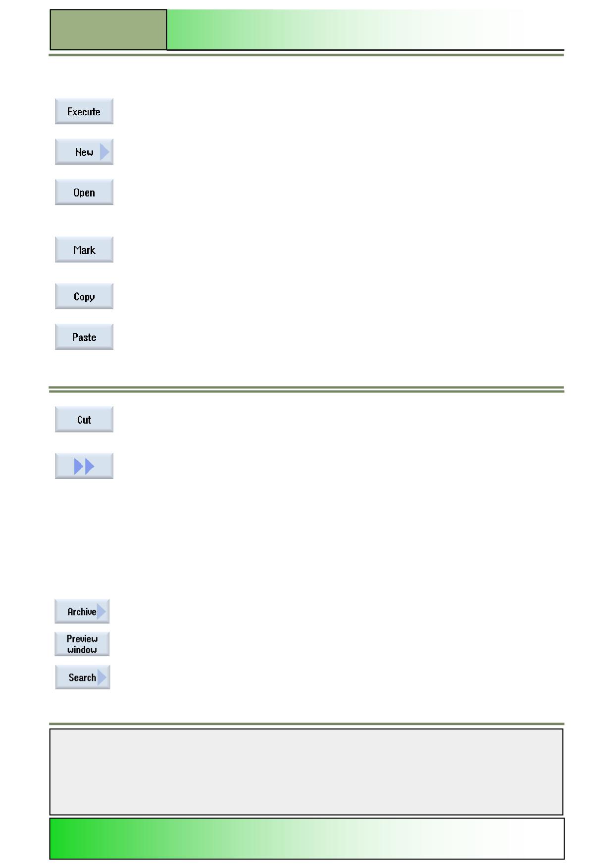
By pressing the VSK 1.1 “Execute“ you can select a program and change over to the operat-
ing area “Machine” in order to start machining the selected program.
By pressing the VSK 1.2 “New“ you can create a new directory. In the selected directory you
can create a new ShopMill or a programGUIDE program .
By pressing the VSK 1.3 “Open“ the selected program (marked with an orange cursor) will be
opened.
Alternatively you can also press the yellow “INPUT” key on the keyboard or the blue “cursor
to the right”-key to open a program.
By pressing the VSK 1.4 “Mark“ several programs or directories can be marked for copying or
cutting.
By pressing the VSK 1.5 “Copy” one or several programs or directories can be copied.
By pressing the VSK 1.6 “Paste” the copied program(s) or directorie(s) are inserted into the
selected place in the directory tree of the NC, of a local drive or an USB drive.
By pressing the VSK 1.7 “Cut“ one to several programs or directories can be cut out and in-
serted somewhere else on a location in the directory tree of the NC, a local drive or on an
external USB drive.
By pressing the VSK 8 “Extend” the extended vertical softkey bar 2 with new functions will be
displayed.
Note:
Files can not be copied under the same name into the same directory.
The files are to be renamed.
Vertical softkey bar 2
Display area
Description (continuation)
By pressing the VSK 2.1 “Archive” a new vertical softkey bar is opened.
By pressing the VSK 2.2 “Preview window“ a sub window opens below the file browser win-
dow, with a preview of the program code of the selected program.
By pressing the VSK 2.3 “Search“ you can search for “File name”, using the Vertical softkeys.
Notes
M575
Page 6
828D/840Dsl SINUMERIK Operate
Operating area “Program manager“
M575
Vertical softkey bar 2
Display area
Description (continuation)
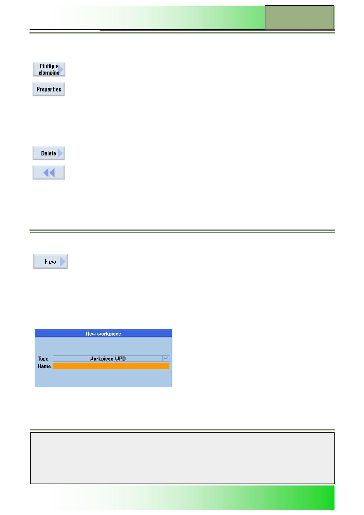
By pressing the VSK 2.5 “Multiple clamping“ you can optimize tool changes over several
workpiece clamping.
By pressing the VSK 2.6 “Properties“ the “Properties of ...” input mask opens where you can:
View program path and modify the program name.
View the time and date of creation.
View the time and date of last changing of the program or folder.
User rights for execution, writing, listing and reading of files and folders.
By pressing the VSK 2.7 “Delete“ the program or folder marked with the cursor will be deleted.
By pressing the VSK 2.8 “Back“ on the operator panel (OP) you switch back to the vertical soft-
key bar 1.
Starting a new NC-program
Press the VSK 1.2 “New“ to start a new G-code program or workpiece. Depending on the
cursor position the following input masks open.
If the cursor is placed on the folder for part programs or subprograms, then a new G-code program of the type “*.MPF” (for
part programs) or “*.SPF” (for subprograms) is created by pressing the VSK 1.2 “New”.
In the name field of the input mask, a name for the program with a maximum of 28 characters (name + point + extension)
has to be entered.
Cursor is positioned on the directory (DIR):
With the VSK 2.1 “Directory” you can create a new Workpiece
directory (WPD).
Cursor is positioned on or in the workpiece directory (WPD):
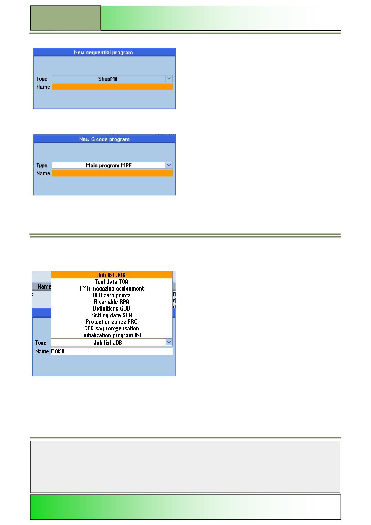
Press the VSK 2.3 “ShopMill” to create a new sequential program.
Notes
828D/840Dsl SINUMERIK Operate
Page 7
M575
M575
Operating area “Program manager“
Starting a new NC-program
Press the VSK 2.4 “programGUIDE G-code” to create a new G-code program. In this case you select between a
main program (MPF) or a subprogram (SPF).
You can create a program of any type in every directory or subdirectory by pressing the VSK 5 “Any”. However in
the area “local drive” and “USB” this does not apply. Only in the area “NC” you can create a program of different
types (see the type list below).
After pressing the VSK 1.2 “New” the following functions in the vertical softkey bar are available.
Notes
M575
Page 8
828D/840Dsl SINUMERIK Operate
Operating area “Program manager“
M575
Vertical softkey bar
Display area
Description
By pressing the VSK 2 “Directory“ you can create a new workpiece of the type *.WPD
(Workpiece directory).
The current cursor position determines the folder where the workpiece is created.
The “New workpiece” window opens.
Note: The softkey is only available if the HSK 1 “NC“ was selected before.
By pressing the VSK 2.3 “ShopMill” a new sequential program will be created.
By pressing the VSK 2.4 “programGUIDE G code”, a new main program or subprogram will be
created, depending on the program type selected in the input mask.
By pressing the VSK 2.6 “Any“ an arbitrary program depending on the file type can be created
(see the picture above).
By pressing the VSK 2.7 “Cancel“ the actual selection will be discarded and the window closed.
By pressing the VSK 2.8 “OK“ or pressing the “INPUT”-key on the keyboard the entered values
or selection made will be accepted and the window closed.
Parameters for “New workpiece“
Parameter
Meaning
Type:
Program type:
WPD
Workpiece directory
Name
Program name:
The program name can only consist of a maximum number of 28 characters (Name + dot + 3-
character extension, e.g. *.WPD).
Permissible characters include all upper-case letters (without accents), numbers, and under-
scores (_).
Parameters for „New G code program“
Parameter
Meaning
Type:
Program type:
MPF
Program (Main program file)
SPF
Subprogram (Subprogram file)
Name
Program name
(see section above)
Notes
828D/840Dsl SINUMERIK Operate
Page 9
M575
M575
Operating area “Program manager“
Parameters for “Any new program“
Parameter
Meaning
Template
If templates are available, they are shown and selectable.
Type:
Program type:
MPF
Program (Main program file)
Name
Program name (see section above)
Marking directories / NC-programs
First open the desired directory in the program manager, like described in sections 2.1 and 3.1.
1.
Place the cursor with the blue “cursor down”-key on the first program or folder that you want to
mark.
2.
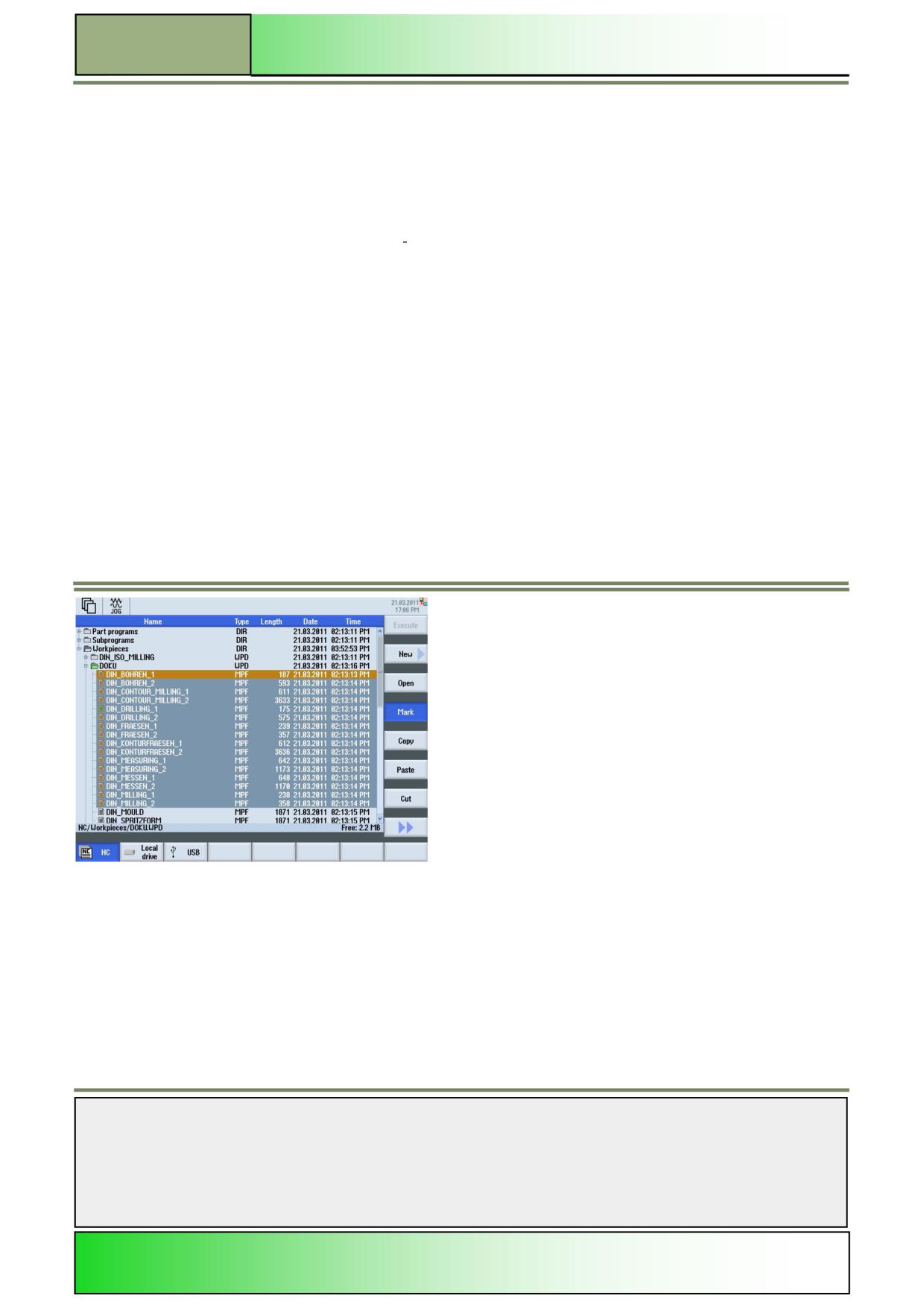
Press the VSK 4 “Mark“.
The program or directory selected with the orange cursor is marked.
3.
Mark more NC-programs or directories by pressing the blue “cursor down”-key.
All selected files or directories are marked grey.
Thereafter, the marked NC-programs can stored to the clipboard of the PCU by pressing the VSK 5 “Copy” or the VSK 7
“Cut” .
The programs stored to the clipboard can then be:
Copied in a different directory or to a different storage device
Deleted from a directory (cut) and pasted into a different directory or storage device.
Tip 1:
To shortcut the marking process place the cursor on the first program or directory you want to copy.
Now press the “SHIFT”-key on the keyboard, hold it pressed and move the cursor with the blue “cursor down” key to the
last program or directory you want to copy. Release the “SHIFT”-key.
The files are now marked.
Notes
M575
Page 10
828D/840Dsl SINUMERIK Operate

Operating area “Program manager“
M575
Tip 2:
If you only want to mark a single program or directory place the cursor on the file and press the blue “SELECT”-key on the
keyboard.
The single file is now selected.
Go on with copying, cutting or deleting, like described next.
Copying and pasting directories / NC- programs
First open the desired directory in the program manager, like described in this module.
1.
Move the cursor with the blue cursor keys to the directory or file which you want to copy. If you want to copy
more then one program or directory, mark them first with the VSK 4 “Mark”.
2.
Press the VSK 5 “Copy“.
3.
If the program is to be copied into another directory on the NC, move the cursor with the “cursor to the
left”-key to the next higher level of the directory tree.
4.
Select the new directory where you want to copy the data with the “cursor up” and “cursor down”-key and
open the directory by pressing the “cursor to the right” or the yellow “INPUT”-key on the keyboard.
5.
Alternatively you can select another storage medium e.g. local drive or USB drive on the horizontal softkey
bar.
6.
By pressing the VSK 6 “Paste“ the program or directory can be inserted into the selected location.
Accept with pressing the VSK 8 “OK” or abort with pressing the VSK 7 “Cancel”.
The original file remains.
Tip 3:
To shortcut the copying process place the cursor on the program or directory you want to copy and press the CTRL + C
keys on the keyboard at the same time. In order to paste the file to another location move the cursor to that location and
press CTRL + V at the same time.
Cutting out directories / NC-programs
First open the desired directory in the program manager, like described in this module.
1.
Move the cursor with the blue cursor keys to the directory or file which you want to cut out. If you want to cut
out more then one program or directory, mark them first with the VSK 4 “Mark”.
2.
Press the VSK 7 “Cut“.
In the message line the message “1 element has been cut. It can now be pasted” will be displayed.
3.
If the program or directory is to be moved to another directory on the NC, move the cursor with the “cursor
to the left”-key to the next higher level of the directory tree.
4.
Select the new directory with the “cursor up” and “cursor down”-key where you want to insert the data and
open the directory by pressing the “cursor to the right” or the yellow “INPUT”-key on the keyboard.
5.
Alternatively you can select another storage medium (e.g. USB stick) on the horizontal softkey bar.
Tip 4:
To shortcut the cutting out of a program or directory place the cursor on the selected file and press the CTRL + X keys at
the same time.
6.
Press the VSK 6 “Paste“ to insert the clipped data to the directory or storage location of your choice. Accept
your selection by pressing the VSK 8 “OK” or abort with pressing the VSK 7 “Cancel”. The source file or
directory will be deleted.
Notes
828D/840Dsl SINUMERIK Operate
Page 11
M575
M575
Operating area “Program manager“
Deleting directories / NC-programs
1.
Move the cursor with the blue cursor keys to the directory or file which you want to copy. If you want to copy
more then one program or directory, mark them first with the VSK 4 “Mark”.
Press the VSK 2.7 “Delete“ in the extended vertical softkey bar 2. Accept the deletion process with pressing
2.
the VSK 8 “OK” or abort with pressing the VSK 7 “Cancel”.
The selected program or directory will be deleted.
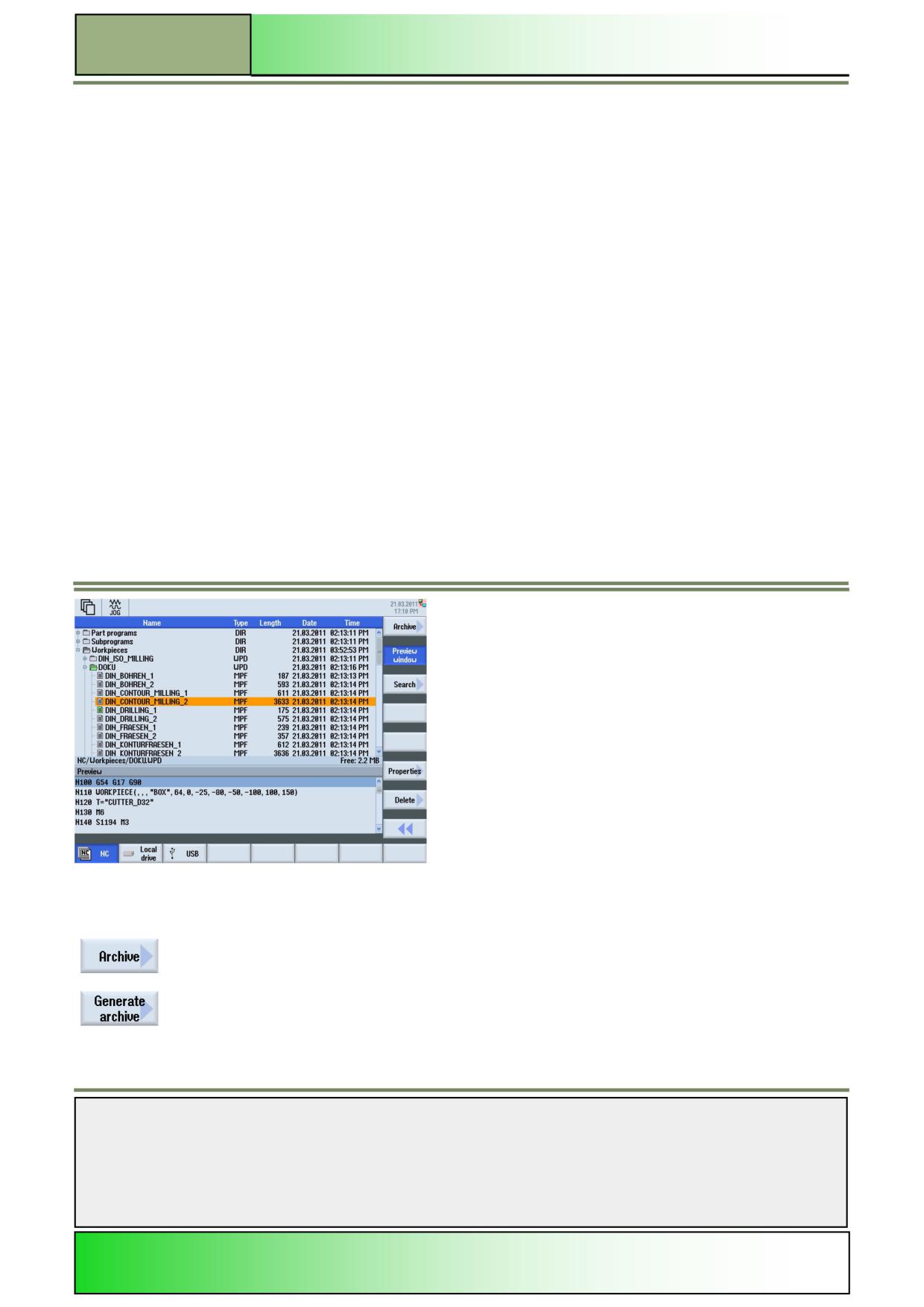
Opening a preview window
1.
Press the VSK 2.2 “Preview window” in the extended VSK-bar. The preview sub window opens directly
below the program manager window.
2.
Use the blue cursor keys to navigate to the program you want to preview. The program code of the selected
program is now displayed in the preview window.
3.
To deselect the function press the VSK 2.2 “Preview window” again.
The preview window disappears.
Note: You cannot edit program code in the “preview window”.
Tip 5: Press the “NEXT WINDOW“-key on the keyboard to activate the preview window. Now you can navigate freely
through the program code by using the blue cursor keys.
Tip 6: The preview window stays active, even if you switch back to the vertical softkey bar 1, in order to copy or cut a pro-
gram or directory.
Generating archive files of programs and directories
Vertical softkey bar
Pressing the VSK 2.1 “Archive” in the extended VSK-bar, will open the next vertical softkey
bar.
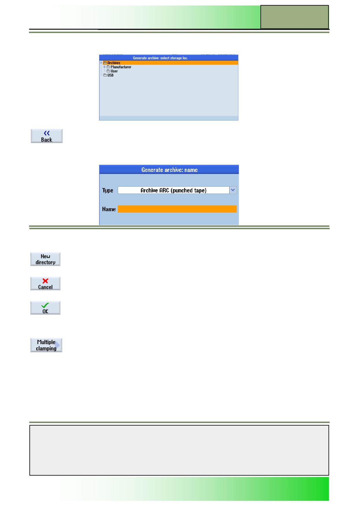
After pressing the VSK 3.1 “Generate archive” the following input mask appears to select the
storage location.
Notes
M575
Page 12
828D/840Dsl SINUMERIK Operate
Operating area “Program manager“
M575
Generating archive files of programs and directories
Vertical softkey bar
With the VSK 3.7 “Back” you can go back to the previous vertical softkey bar.
Afterwards the storage location is selected the next mask appears to enter the name of the
archive file.
Generating archive files of programs and directories
Vertical softkey bar
Pressing the VSK 4.2 “New directory” will open an input mask “New directory”, where you can
define a new directory at the selected cursor position.
Pressing the VSK 4.7 “Cancel” will abort the generating of archive files and the first vertical
softkey bar is selected.
Pressing the VSK 4.0 “OK” will start generating the archive file.
3.11
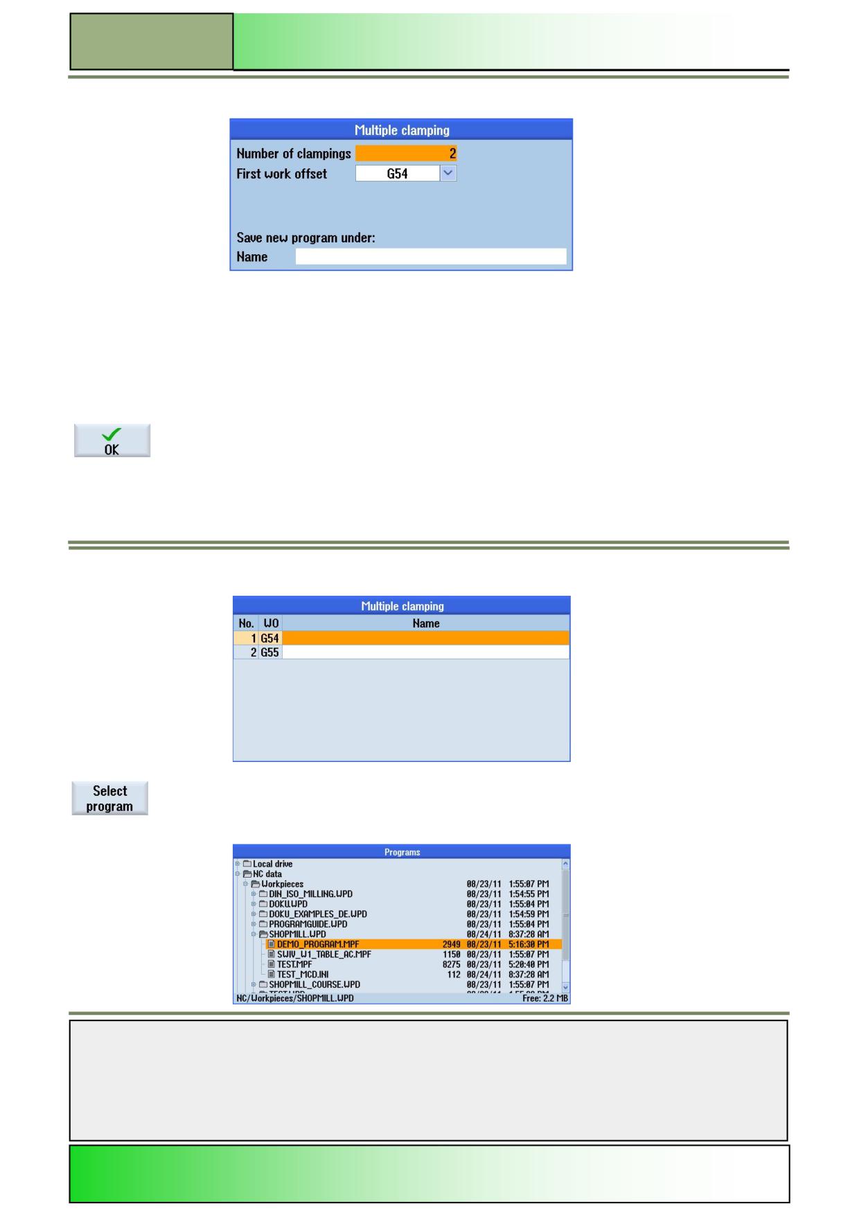
Multiple clamping
By pressing the VSK 2.5 “Multiple clamping“ you can optimize tool changes over several work-
piece clamping
Notes
828D/840Dsl SINUMERIK Operate
Page 13
M575
M575
Operating area “Program manager“
Multiple clamping
Parameters
Meaning
Number of clampings:
Total number of workpieces being machined..
First work offset:
Choose the first work offset to be used for “multiple clamping..
Name:
Name of the new program with optimized tool clamping over several workpiece clamping.
By pressing the VSK 8 “OK” all parameters and names will be accepted.
Multiple clamping continued
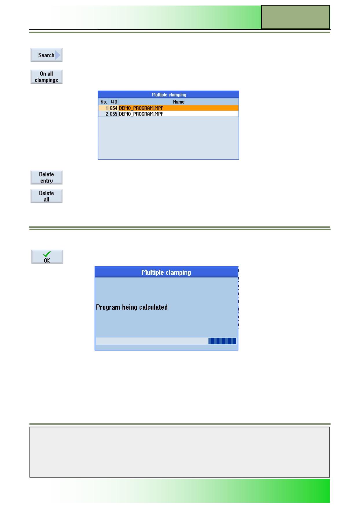
By pressing the VSK 2.1 “Select program“ you can choose the programs for optimizing tool
changes over several workpiece clamping.
Notes
M575
Page 14
828D/840Dsl SINUMERIK Operate
Operating area “Program manager“
M575
Multiple clamping continued
By pressing the VSK 2.3 “Search“ you can search for “File name”, using the Vertical softkeys.
By pressing the VSK 2.6 “On all clampings“ you can apply the same file name to all clamping.
By pressing the VSK 2.5 “Delete entry“ you can delete the file name that the curser has high-
lighted .
By pressing the VSK 2.6 “Delete all“ you can delete all file names for each clamping name.
Multiple clamping continued
By pressing the VSK 8 “OK” all parameters and names will be accepted.
The multiple clamping program is then calculated.
Notes
828D/840Dsl SINUMERIK Operate
Page 15
M575
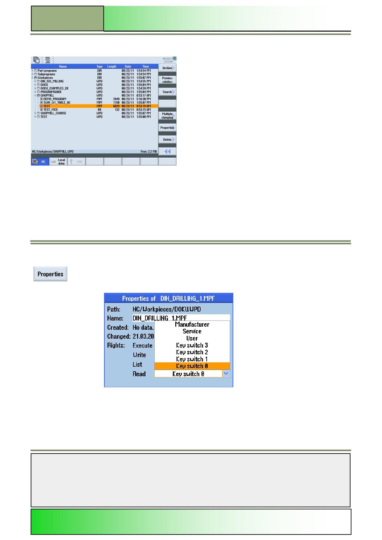
M575
Operating area “Program manager“
Multiple clamping continued
Properties of programs and directories
By pressing the VSK 2.6 “Properties” in the extended vertical softkey bar depending on the
cursor position and the selected program (here TEST.MPF) the “properties of
” window with
security options for the selected program or directory opens.
Note: You can change the program name and the rights.
Parameters
Meaning
Path and name:
Program path and Program name;
The program with the name “TEST1.MPF” is located in the folder NC/Workpieces/DOKU.
Notes
M575
Page 16
828D/840Dsl SINUMERIK Operate
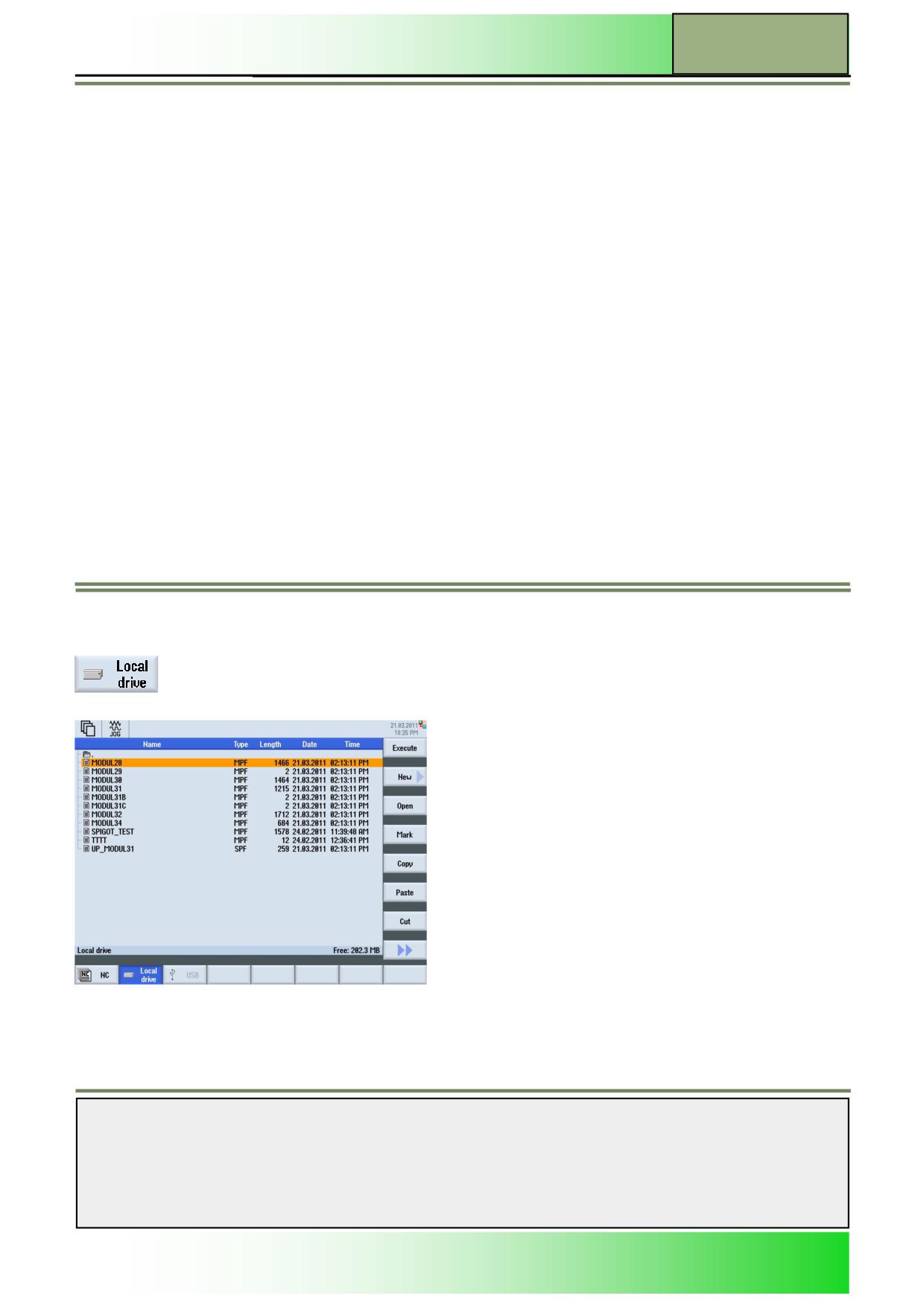
Operating area “Program manager“
M575
Properties of programs and directories
Created:
Date and time of creation:
On the right side of the field “Created”: Date and time of creation are displayed here.
Changed:
Date and time change:
On the right side of the field “Changed”: Date and time since the last edit of the program are
displayed.
Rights:
User rights for executing, writing, listing and reading of a program or directory.
7 protection levels are possible (level 1 highest protection level, level 7 the lowest).
Protection level 1
Manufacturer
Protected by password
Protection level 2
Service
Protected by password
Protection level 3
User
Protected by password
Protection level 4
Programmer
Key switch 3
Protection level 5
Qualified worker
Key switch 2
Protection level 6
Skilled worker
Key switch 1
Protection level 7
Semi skilled worker
Key switch 0
Storage medium “Local drive”
Selecting the function “Local drive“
By pressing the HSK 2 “Local drive“ the program manager shows the directory structure of the
local drive.
A complete listing of all folders and files of the local drive is shown in the program manager window. For a description of the
information of name, type, length and date/time displayed in this window.
Notes
828D/840Dsl SINUMERIK Operate
Page 17
M575
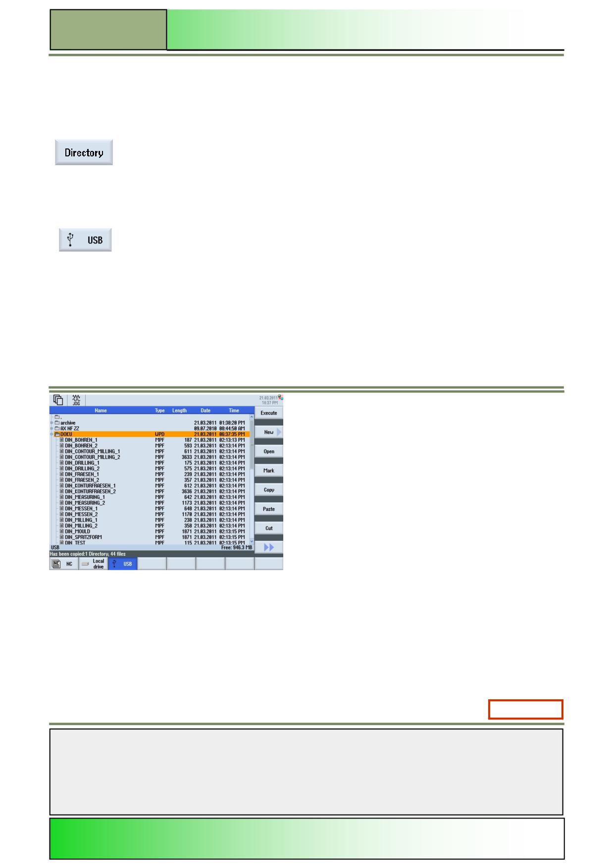
M575
Operating area “Program manager“
Vertical softkey bar
The full functionality available under the NC program manager window is available by pressing the HSK 2 “local drive” or
HSK 3 “USB” (see section 3 in this module).
Additional, here you can create a new directory by pressing the VSK 1 “Directory”.
By pressing the VSK 1 “Directory” the “New directory” input mask opens where you can create
a new directory on the local drive.
Enter a name for the new directory and accept with pressing the VSK 8 “OK”, or abort with the
VSK 7 “Cancel”.
Storage medium “USB” drive
Selecting the function “USB“
By pressing the HSK 3 “USB“ the following directory tree of the USB drive is displayed.
A complete listing of all folders and files of the USB drive is shown in the program manager window. For a description of
the information displayed in this window, see section 3.
Vertical softkey bar
The full functionality available under the NC program manager window is available by pressing the HSK 2 “local drive” or
HSK 3 “USB”.
M575: END
Notes
M575
Page 18
828D/840Dsl SINUMERIK Operate
M600
Basics of programming with ShopMill
Sinumerik
Operate
Module Description:
This module explains the general structure of a ShopMill program which includes the program head-
er, the program block and the program ending. In addition to this, the programming of chained pro-
gramming blocks (sequential programs), the functions of the “Editor”, as well as the functions
“Various”, Simulation” and “NC Execute” will be described.
Module Objective:
Working with this module you will learn the basics of creating ShopMill sequential pro-
grams.
Content:
Basics
Creating ShopMill programs
Editor
Various
Simulation
NC Execute
This document was produced for training purposes.
828D/840Dsl SINUMERIK Operate v4.7
Page 1
M600
Siemens assumes no responsibility for its contents.
M600
M600
Page 2
828D/840Dsl SINUMERIK Operate

Basics of programming with ShopMill
M600
Basics of
programming with
Shopmill:
START
Basics
Creating
ShopMill
programs
Editor
Various
Simulation
NC Execute
Basics of
programming with
Shopmill:
END
Notes
828D/840Dsl SINUMERIK Operate
Page 3
M600
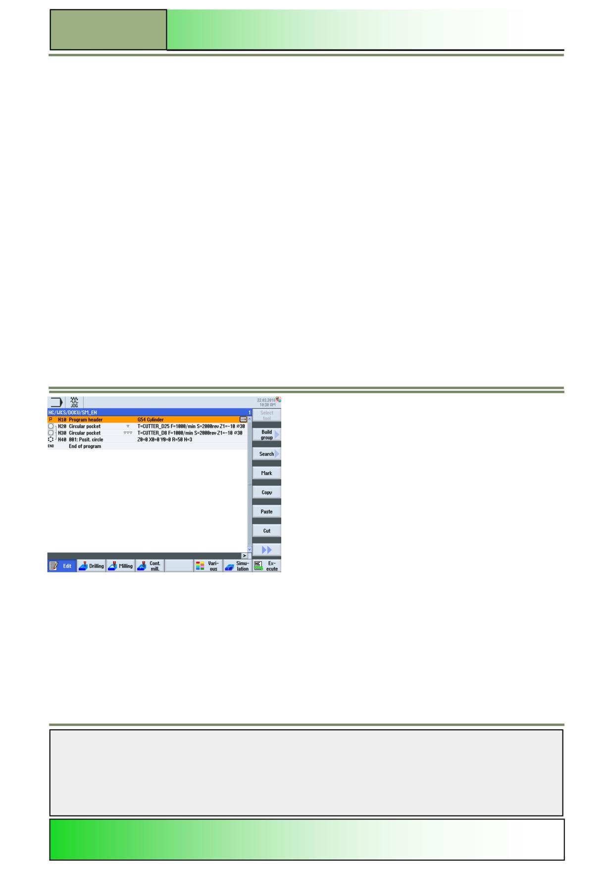
M600
Basics of programming with ShopMill
Basics
Programming with ShopMill
ShopMill offers the option to create NC programs directly on the control in the manner of chained sequential block pro-
grams. It also offers the option to program G-code programs directly, with additional ShopMill functionality.
Note:
The creation of G code programs under ShopMill is described in detail in module - M604 “Basics of programming program-
GUIDE“.
The advantage of programming a ShopMill program lies in the graphical guiding of the programming process in the editor.
The following functions are available for this task:
Technology oriented program step selection (technology/cycles) using softkeys
Input masks and windows for parameters, with animated help graphics
Context sensitive online help for every input mask and window
Support for the contour input (geometric processor)
ShopMill programs can be represented in different views:
As a work plan, showing the program header, the programming steps with their linkages (chains) and the end of the
program.
Notes
M600
Page 4
828D/840Dsl SINUMERIK Operate
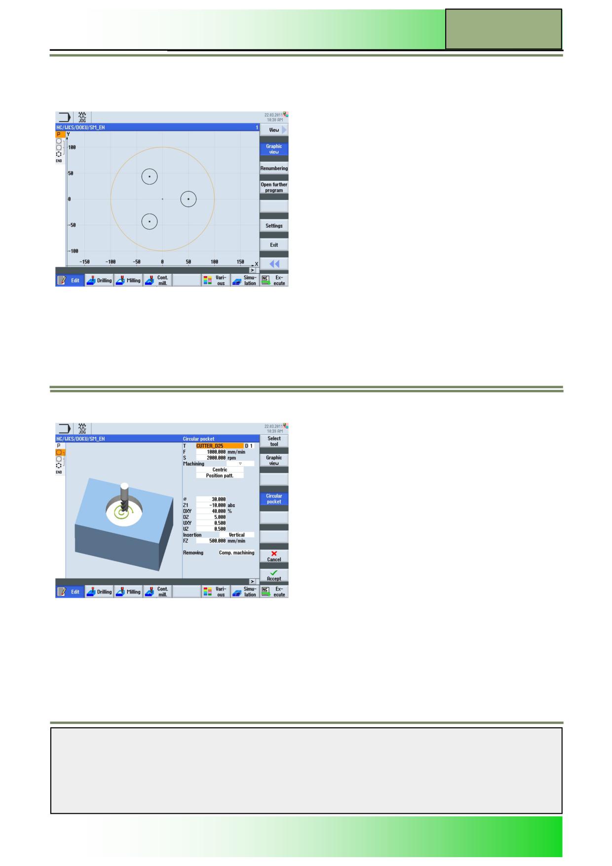
Basics of programming with ShopMill
M600
As a programming graphic in the graphic view (with activated VSK 2.2 “Graphic view”): The workpiece or machining
step are shown as an outline graphic in side view or top view. The marked program block in the work plan is shown with
a different colour.
As a parameter mask with a help graphic in 3-D, or a simulation of the machining step in side view or top view.
If available, the view changes continuously from Help picture to animation.
The animated help graphics are displayed always in the correct position to the adjusted coordinate system. The parameters
are dynamically overlayed into the graphic and are highlighted in a different colour.
Notes
828D/840Dsl SINUMERIK Operate
Page 5
M600
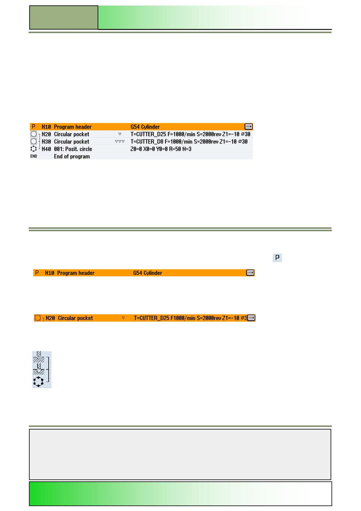
M600
Basics of programming with ShopMill
The work plan
Main aspect of programming with ShopMill is the “Work plan” in the editor window. The structure of the “Work plan” is as
below:
Program header (with the base settings of the program like measuring units, work offset, blank dimensions, retraction
plane, safety distance etc.)
Program blocks (the program steps with the cycles)
End of program (see also picture below)
Program header
The program header contains the dimensions of the blank for the simulation, as well as the parameters that influence the
whole program, as for example:
Work offset
Dimension units (mm/inch)
Tool axis X, Y or Z
Retraction plane, safety distance and machining sense
In the work plan, the program header is at the beginning of the program and is labelled with the icon
, and the signature
“Program header” and the corresponding parameters (see picture below).
Program blocks
Program blocks are programmed working steps, which are shown in the editor in single rows marked with an icon and text
representing the corresponding technology and the entered parameters (alike the picture below).
Sequential program blocks
For the functions “Drill”, “Mill”, and “Contour milling”, technology blocks and contours are programmed sepa-
rately. These programming blocks are automatically linked by the control and connected in the work plan with
square brackets. Technology blocks are blocks that describe in which manner the machining is to be pro-
cessed, such as for instance centring and drilling. Position blocks or geometry blocks respectively, de-
scribe the positions where machining takes place, e.g. holes on a bolt hole pattern. A sequential program
block (chain) is only considered closed, if one ore more Technology blocks, end with a Position block. A
error massage will be output if one of these elements is missing.
Notes
M600
Page 6
828D/840Dsl SINUMERIK Operate
Basics of programming with ShopMill
M600
The icons of these blocks are marked by a square bracket, right beside the Technology block icon, from the
beginning of the program chain to the end of the program chain. Every technology is represented by a unique
icon. This icon and its chaining are also displayed on the left edge of the screen in the programming graphics
and parameter input masks. (here centering, drilling and position circle).
End of program
The program end indicates to the control the end of the processing of the workpiece. Besides, you can define to repeat the
program for multiple work pieces. The program end is marked with the icon
and the text “End of program” and if se-
lected with the text “Repetition = Yes” (see picture below).
G code programming steps
In the work plan, G code program blocks can also be inserted.
For this, you must place the cursor on the desired position in the editor window, where you want to insert the G code block.
Pressing the yellow “INSERT”-key on the keyboard, opens a new orange command line, marked with the letter G and a
blinking cursor where you can enter G code commands. With the blue “cursor up” or “cursor down” the block can be
closed. The input value is now accepted. From a G code line you can not switch to a parameter mask window.
Navigation in the editor window
For a fast and comfortable navigation within a sequential program and the parameter masks you can use the blue cursor
keys.
With the blue “cursor-up” key on the keyboard you can navigate upwards in the program editor
and the parameter masks.
With the blue “cursor-down”-key on the keyboard you can navigate downwards in the program
editor and the parameter masks.
The arrow symbol (extend-symbol) on the right side of program block line in the editor window
indicates that you can enter the parameter input mask by pressing the “cursor-to-the-right”
key.
The “cursor-to-the-right” key opens the parameter mask of the corresponding program block.
The “cursor-to-the-left” key closes the parameter mask of the corresponding program block
and brings you back to the editor window, displaying the ShopMill program steps.
Notes
828D/840Dsl SINUMERIK Operate
Page 7
M600