SINUMERIK 840D sl. Training. Operate - Turning (2016-2020) - page 14
System overview
2.2 SINUMERIK 840D sl
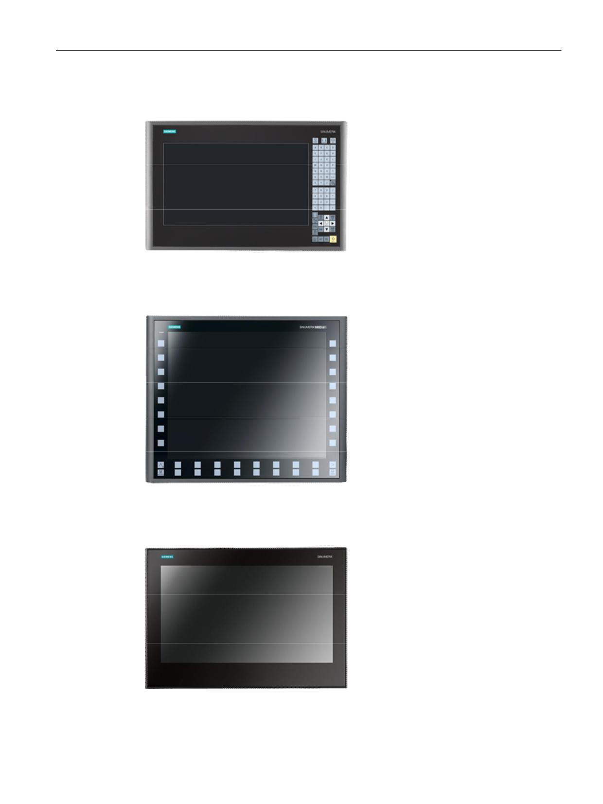
SINUMERIK OP 015 black
x Operator panel 396 mm wide,
15.6" TFT display
(resolution 1366 × 768 pixels)
x Capacitive keyboard with 64 keys
x Capacitive display area for gesture
operation (touch operation)
Note: see also Chapter Multitouch operation
(Page 27)
SINUMERIK OP 019
x Operator panel 483 mm wide,
19" TFT display
(resolution 1280 × 1024 pixels)
x Version with membrane keys, gloved
operation also possible
x Capacitive sensor equipment for fast key
operation
x Integrated key disable as protection
against incorrect operation
x USB 2.0 connector socket for console
installation
x Separate CNC keyboard and machine
control panel
SINUMERIK OP 019 black
x Operator panel 46.99 cm wide,
18.5" TFT display
(resolution 1366 × 768 pixels)
x Permits the distributed installation of the
operator panel front and the controller
x Capacitive display area for gesture
operation
Note: see also Chapter Multitouch operation
(Page 27)
SINUMERIK Operate - Milling
Control system overview for machine tools' sales people, 2017, A5E41992599B AA
19

System overview
2.2 SINUMERIK 840D sl
SIMATIC Industrial Thin Client
SIMATIC Industrial Thin Client
x Touch operation
x Connection via Ethernet
Versions:
SIMATIC ITC 1200, 12" widescreen TFT dis-
play
(resolution 1280 x 800 pixels)
SIMATIC ITC 1500, 15" widescreen TFT dis-
play
(resolution 1280 x 800 pixels)
SIMATIC ITC 1900, 19" widescreen TFT dis-
play
(resolution 1366 x 768 pixels)
Note: see also Chapter Multitouch operation
(Page 27)
SINUMERIK Operate - Milling
20
Control system overview for machine tools' sales people, 2017, A5E41992599B AA

System overview
2.2 SINUMERIK 840D sl
2.2.2
Operator panel equipment
PCU 50
We offer the PCU 50.x for customers who specify a hard disk and/or supplementary
Windows-based software.
Ⴠ Windows 7 operating system
Ⴠ Up to 40 GB for data (part programs, documentation, other data)
Ⴠ Additional PCI slots
Ⴠ Additional CF card slot
Ⴠ DVI interface
SINUMERIK Operate - Milling
Control system overview for machine tools' sales people, 2017, A5E41992599B AA
21

System overview
2.2 SINUMERIK 840D sl
SIMATIC IPC
Panel PC variant up to 19" panels for multitouch operation:
Ⴠ Compact and rugged
Ⴠ Solid State Drive (SSD)
Ⴠ Passive cooling
Ⴠ Specific configuration for SINUMERIK
SINUMERIK Operate - Milling
22
Control system overview for machine tools' sales people, 2017, A5E41992599B AA

System overview
2.2 SINUMERIK 840D sl
2.2.3
Handheld units
Mini handheld unit
The following mini-handheld unit is suitable for the machine setup:
SINUMERIK HT 2
The SINUMERIK HT 2 handheld terminal is designed to allow machine tools to be operated
manually if you need to remain mobile during operation (e.g. for setup activities). It has been
developed specifically with the focus on easy handling, ruggedness and to address the
actual requirements met in practice.
SINUMERIK Operate - Milling
Control system overview for machine tools' sales people, 2017, A5E41992599B AA
23

System overview
2.2 SINUMERIK 840D sl
SINUMERIK HT 8
The mobile SINUMERIK HT 8 handheld ter-
minal combines the functions of an operator
panel and a machine control panel in a single
device.
x Fully graphic 7.5" TFT color display
x Mobility for operator control and monitoring
x Operation via touch screen, membrane
keys and touch pen
x Emergency stop button and 2 enabling
buttons for left-handed and right-handed
operators
x Simple insertion or removal during
operation
x Rugged, compact and ergonomically
designed
Wireless hand-held device Hubitron
For wireless operation, we recommend the Hubitron HBG 800-DP hand-held device.
Further information:
SINUMERIK Operate - Milling
24
Control system overview for machine tools' sales people, 2017, A5E41992599B AA
CNC operation with SINUMERIK Operate
3
3.1
Animated elements
SINUMERIK 828D
SINUMERIK 828D
SINUMERIK 828D
BASIC
ADVANCED
Basic configuration
Basic configuration
Basic configuration
SINUMERIK 840D sl
SINUMERIK 840D sl
BASIC
Basic configuration
Basic configuration
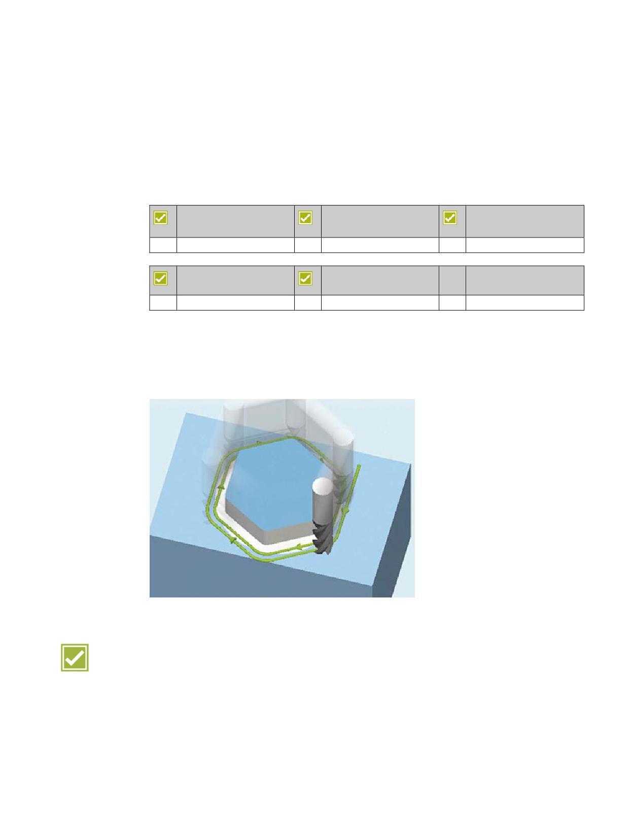
To illustrate which parameters affect what in machining operations, SINUMERIK Operate
offers a new input support function with animated element sequences. For instance, the
difference between chip breakage and chip removal when drilling or the precise probe
sequence for a corner measurement can be shown.
Benefits
Ⴠ Process reliability during the setup
Ⴠ Increased reliability at program input by easily understood depiction of selection options
Ⴠ This results in improved efficiency and so increased availability of the machine
SINUMERIK Operate - Milling
Control system overview for machine tools' sales people, 2017, A5E41992599B AA
25
CNC operation with SINUMERIK Operate
3.2 Onboard documentation
3.2
Onboard documentation
SINUMERIK 828D
SINUMERIK 828D
SINUMERIK 828D
BASIC
ADVANCED
Basic configuration
Basic configuration
Basic configuration
SINUMERIK 840D sl
SINUMERIK 840D sl
BASIC
Basic configuration
Basic configuration
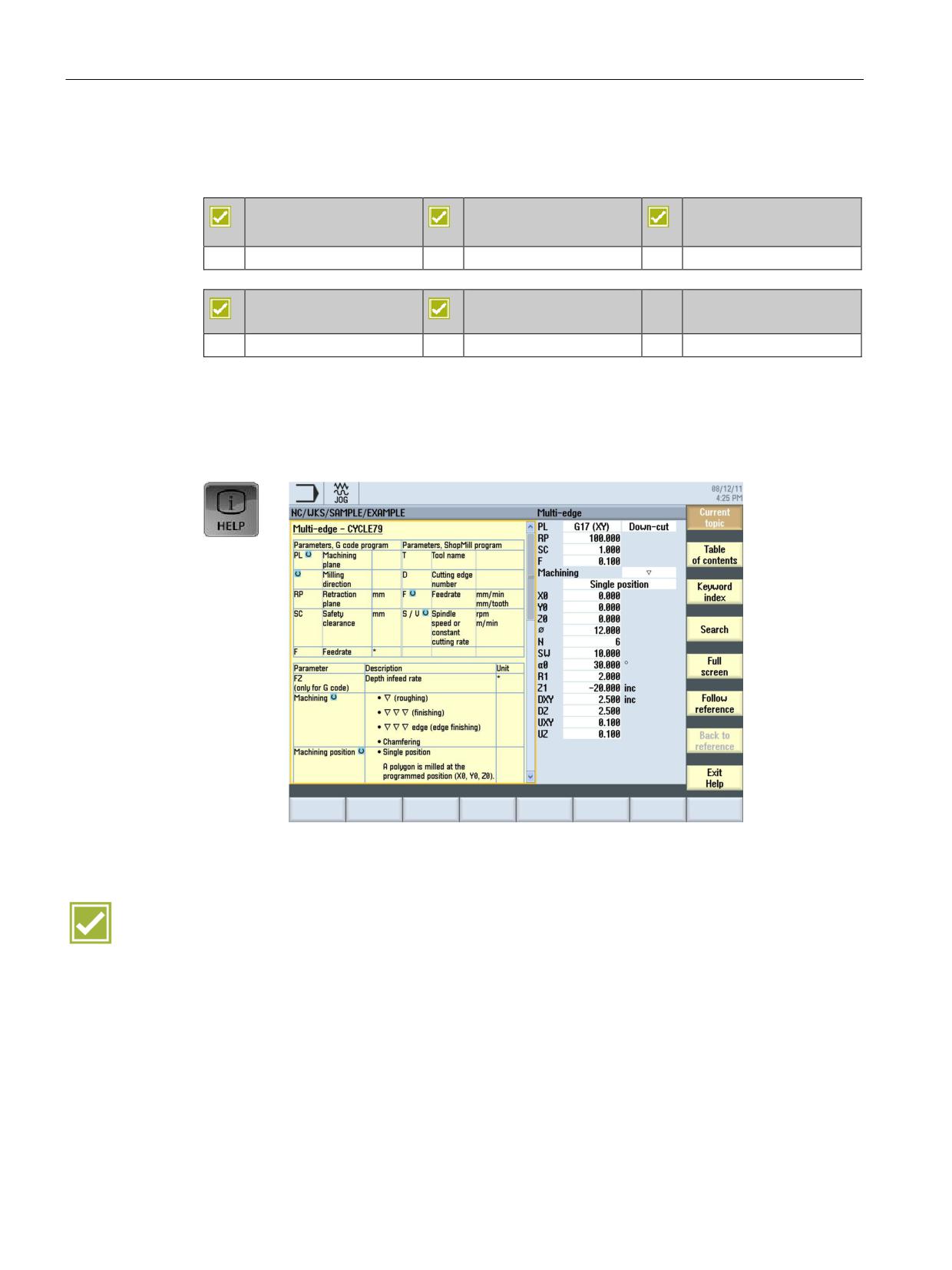
For each input field in the operating screens, SINUMERIK Operate automatically displays
help in the form of a "cursor text". Further information is provided in the form of a complete
context-sensitive help system with many useful details and graphics.
Benefits
Ⴠ Programming on the machine without a handbook
Ⴠ Help button to toggle between the editor and help screens
SINUMERIK Operate - Milling
26
Control system overview for machine tools' sales people, 2017, A5E41992599B AA
CNC operation with SINUMERIK Operate
3.3 Multitouch operation
3.3
Multitouch operation
SINUMERIK 828D
SINUMERIK 828D
SINUMERIK 828D
BASIC
ADVANCED
Basic configuration
Basic configuration
Basic configuration
SINUMERIK 840D sl
SINUMERIK 840D sl
BASIC
Basic configuration
Basic configuration
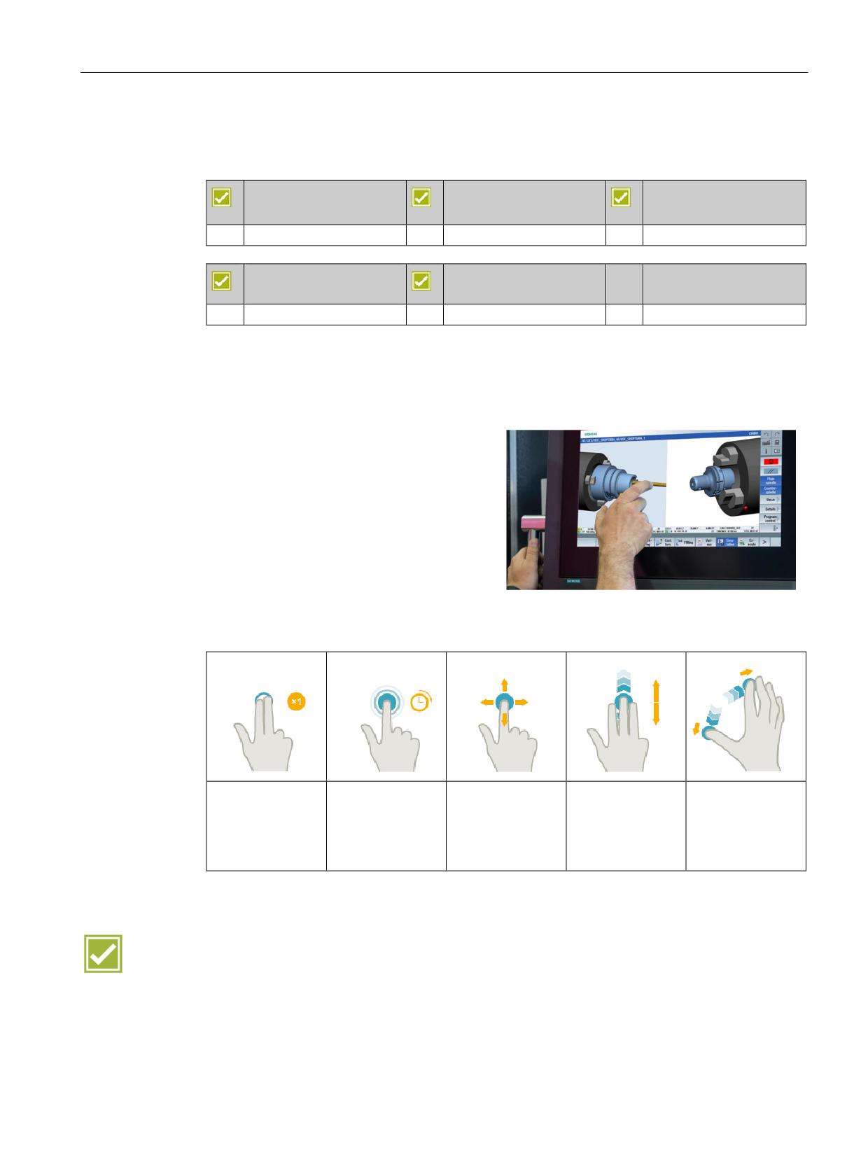
With the appropriate operator panel fronts, SINUMERIK Operate can also be operated with
multitouch gestures. Multitouch operation is possible for the SINUMERIK 840D sl with the
operator panel fronts SINUMERIK OP 015 black line or SINUMERIK OP 019 black line and
for the SINUMERIK 828D PPU 290.3, vertical.
x Intelligent gesture operation with
touchpanels, also with work gloves
x Capacitive touch for industrial use
x Palm detection
x Detection of liquids and contaminations
Extract from the multitouch operation gestures:
Tap with two fin-
Tap and hold
Pan
Flick with three
Spread
gers
fingers
Open object to be
Move graphic
Zoom out graphic
Call the shortcut
changed, e.g. NC
contents, e.g.
Scroll to the start
contents, e.g.
menu, e.g. copy,
block
simulation, mold
or end of lists or
simulation, mold
paste
making view
files
making view
Benefit
Ⴠ Modern and efficient gesture operation of SINUMERIK Operate - rugged and reliable,
even in harsh industrial environments
SINUMERIK Operate - Milling
Control system overview for machine tools' sales people, 2017, A5E41992599B AA
27
CNC operation with SINUMERIK Operate
3.4 Shortcuts
3.4
Shortcuts
SINUMERIK 828D
SINUMERIK 828D
SINUMERIK 828D
BASIC
ADVANCED
Basic configuration
Basic configuration
Basic configuration
SINUMERIK 840D sl
SINUMERIK 840D sl
BASIC
Basic configuration
Basic configuration
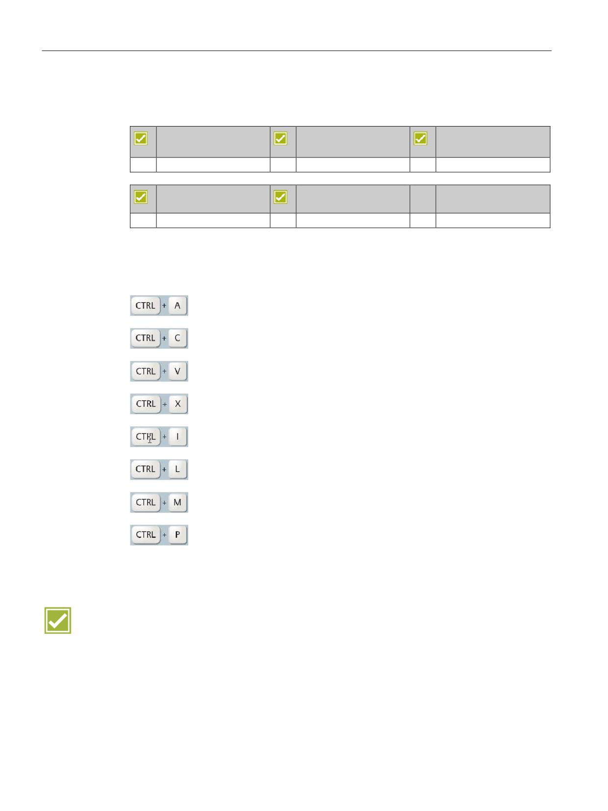
Shortcuts are available for many menu operations in SINUMERIK Operate. A small extract
follows:
Select all (editor functionality)
Copy
Paste
Cut
Calculation of the time from/to line/block
Language selection
Maximum simulation speed
For screenshots
(Storage location: commissioning (keyword) ൺ System data ൺ HMI data ൺ
Logs ൺ Screenshots)
Benefit
Ⴠ Shortcuts in SINUMERIK Operate avoid the need for complicated menu operations and
provide functions not previously expected from a CNC
SINUMERIK Operate - Milling
28
Control system overview for machine tools' sales people, 2017, A5E41992599B AA
CNC operation in manual mode (JOG)
4
4.1
TSM universal cycle
SINUMERIK 828D
SINUMERIK 828D
SINUMERIK 828D
BASIC
ADVANCED
Basic configuration
Basic configuration
Basic configuration
SINUMERIK 840D sl
SINUMERIK 840D sl
BASIC
Basic configuration
Basic configuration
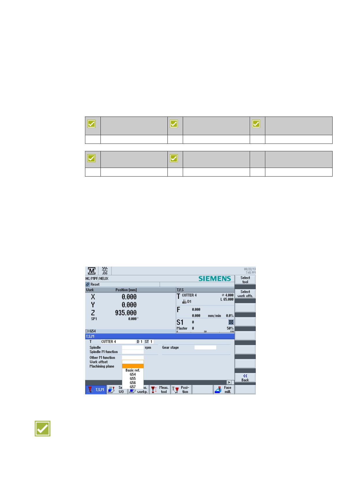
A universal cycle is available in setup mode for the most commonly used machine functions.
These include:
Ⴠ Tool change, also replacement tools, with direct access via the tool table (T)
Ⴠ Spindle speed and direction (S)
Ⴠ M functions (M)
Ⴠ Activation of work offsets
Ⴠ Definition of the gearbox stage
Ⴠ Selection of the machining plane
Benefit
Ⴠ User-friendly manual input function with dialog prompting
SINUMERIK Operate - Milling
Control system overview for machine tools' sales people, 2017, A5E41992599B AA
29
CNC operation in manual mode (JOG)
4.2 Work offsets
4.2
Work offsets
SINUMERIK 828D
SINUMERIK 828D
SINUMERIK 828D
BASIC
ADVANCED
Basic configuration
Basic configuration
Basic configuration
SINUMERIK 840D sl
SINUMERIK 840D sl
BASIC
Basic configuration
Basic configuration
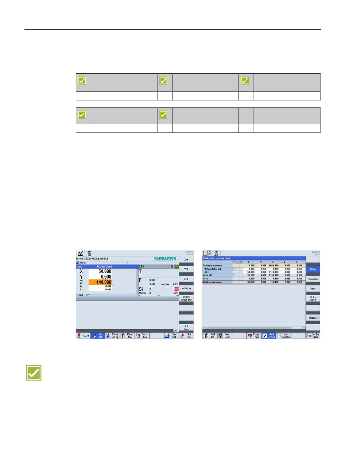
The following work offsets are possible:
Ⴠ Settable work offsets:
It is possible to enter as many as 100 work offsets (G54 to G57, G505 to G599), offset
coordinates, angles and
scaling factors.
Ⴠ Programmable work offsets:
The programmable work offsets allow you, for example, to work with different work offsets
for repetitive machining operations at different positions on the workpiece.
Ⴠ External work offsets:
Axis-related linear work offsets can also be activated via the PLC user software.
Benefits
Ⴠ Flexible machining thanks to a large number of adjustable work offsets
Ⴠ User-conform understandable representation of the number of work offsets
SINUMERIK Operate - Milling
30
Control system overview for machine tools' sales people, 2017, A5E41992599B AA
CNC operation in manual mode (JOG)
4.3 Measuring a workpiece
4.3
Measuring a workpiece
SINUMERIK 828D
SINUMERIK 828D
SINUMERIK 828D
BASIC
ADVANCED
Basic configuration
Basic configuration
Basic configuration
SINUMERIK 840D sl
SINUMERIK 840D sl
BASIC
Basic configuration
Basic configuration
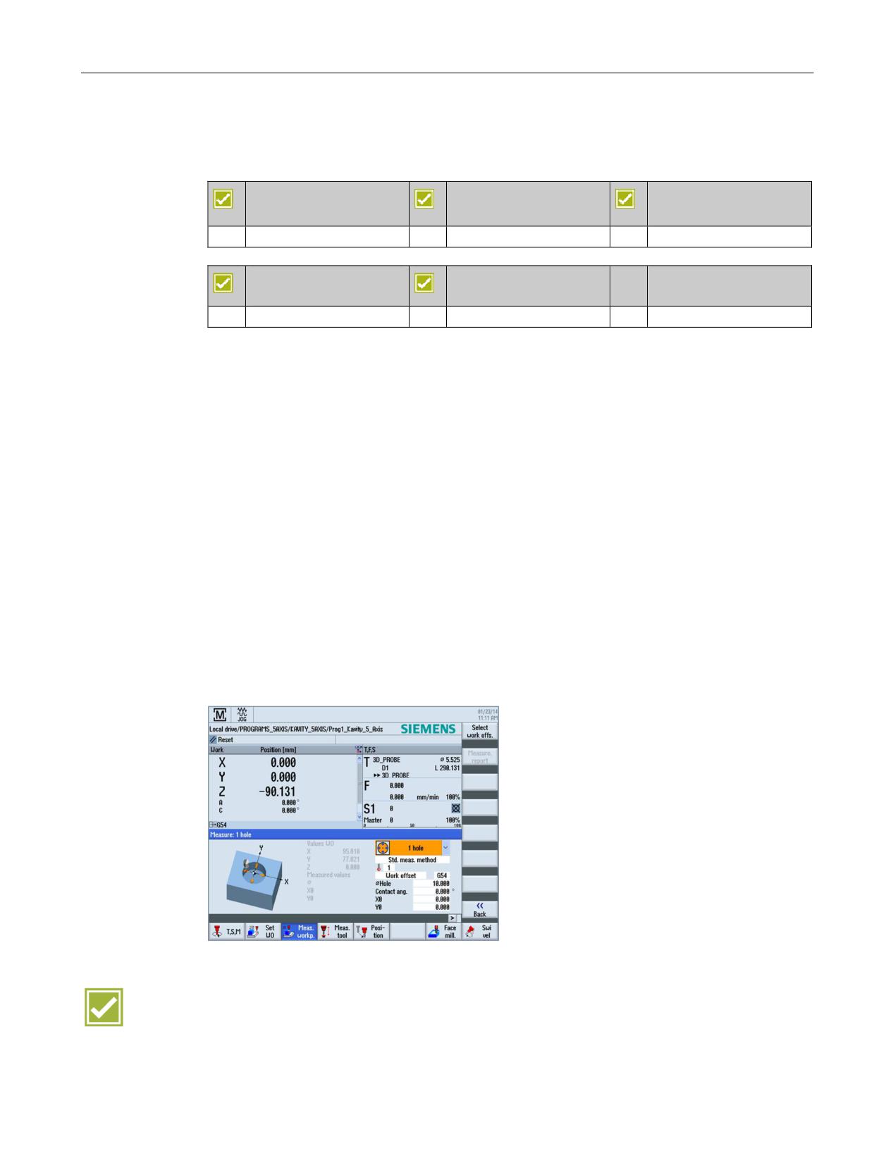
The workpieces can be measured as follows:
Ⴠ Edge finder, dial gauge, reference tool
Ⴠ 3D switching probe.
The following measuring cycles are available:
Ⴠ Calibrate probe
Ⴠ Point measurement for edges
Ⴠ Orienting the edge (angle)
Ⴠ Inner/outer corner (3 or 4 points)
Ⴠ Orienting the edge by means of 2 holes/spigots
Ⴠ Rectangular or circular pockets, rectangular or circular spigots
Ⴠ Center point of 3 or 4 holes or spigots
Ⴠ Orienting the plane with three points
The measurement results can be output in a measuring log (see Chapter Logging
measurement results in JOG (Page 33)).
Benefits
Ⴠ Time saving due to user-friendly determination of the workpiece's clamping position
instead of orienting the workpiece by hand.
Ⴠ The measurement results can be output in a measuring log.
SINUMERIK Operate - Milling
Control system overview for machine tools' sales people, 2017, A5E41992599B AA
31
CNC operation in manual mode (JOG)
4.4 Measuring a tool
4.4
Measuring a tool
SINUMERIK 828D
SINUMERIK 828D
SINUMERIK 828D
BASIC
ADVANCED
Basic configuration
Basic configuration
Basic configuration
SINUMERIK 840D sl
SINUMERIK 840D sl
BASIC
Basic configuration
Basic configuration
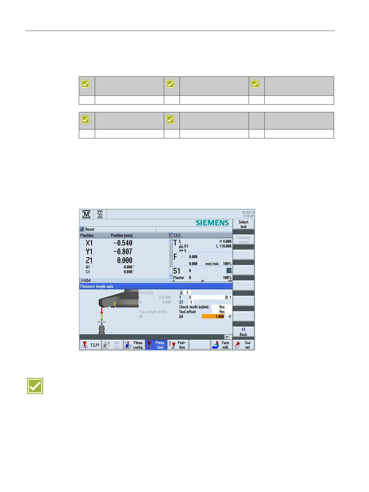
The tool compensation values can be directly determined in setup mode.
The following variants are supported:
Ⴠ Manual or switching probe
Ⴠ Scratching with tool at known workpiece geometry
The measurement results can be output in a measuring log (see Chapter Logging
measurement results in JOG (Page 33)).
Benefit
Ⴠ User-friendly functions for determining the tool dimensions directly in the machine
SINUMERIK Operate - Milling
32
Control system overview for machine tools' sales people, 2017, A5E41992599B AA
CNC operation in manual mode (JOG)
4.5 Logging measurement results in JOG
4.5
Logging measurement results in JOG
SINUMERIK 828D
SINUMERIK 828D
SINUMERIK 828D
BASIC
ADVANCED
Basic configuration
Basic configuration
Basic configuration
SINUMERIK 840D sl
SINUMERIK 840D sl
BASIC
Basic configuration
Basic configuration
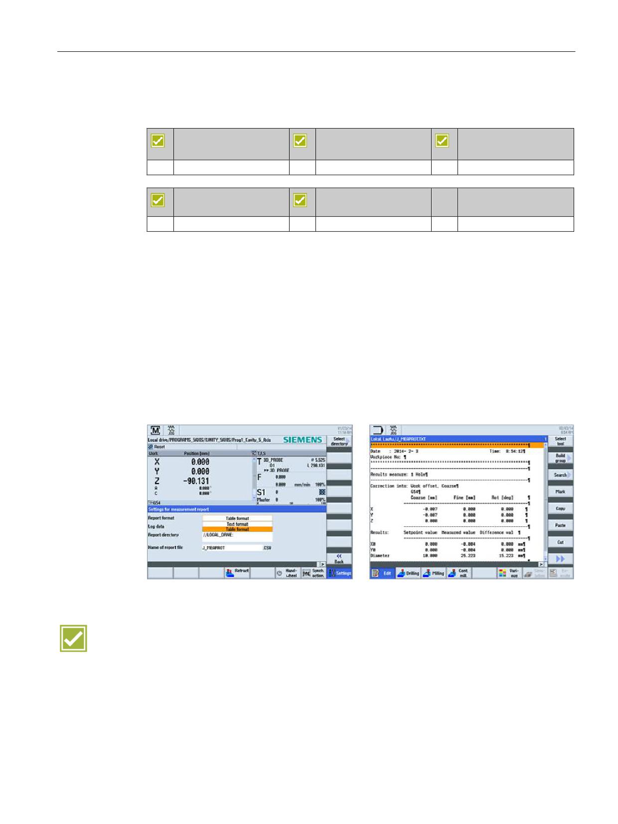
The results for measuring in JOG can be logged. The standard log contains the
measurement results of the most recently performed measuring method.
The function is available as milling technology for the workpiece and tool measurement.
Text format or table format can be selected for the output format
The measuring log comprises the following data:
Ⴠ Date and time when the log was written
Ⴠ Log name with path details
Ⴠ Measuring method
Ⴠ Correction target
Ⴠ Setpoints, measured values and differences
Benefit
Ⴠ Simple logging of measured values in log files
SINUMERIK Operate - Milling
Control system overview for machine tools' sales people, 2017, A5E41992599B AA
33
CNC operation in manual mode (JOG)
4.6 Face milling cycle
4.6
Face milling cycle
SINUMERIK 828D
SINUMERIK 828D
SINUMERIK 828D
BASIC
ADVANCED
Basic configuration
Basic configuration
Basic configuration
SINUMERIK 840D sl
SINUMERIK 840D sl
BASIC
Basic configuration
Basic configuration
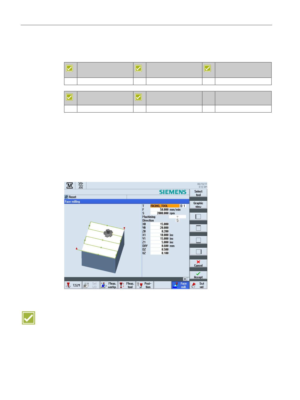
A face milling cycle for preparation of the blank for machining is available directly in setup
mode. You can select the tool directly from the list. Input the feedrate and the spindle speed /
cutting speed.
You can specify the following parameters:
Ⴠ Machining strategy and direction
Ⴠ Machining limitations
The input values are retained even after switching off and on again, so that users can always
restart their face milling operation with minimum effort.
Benefit
Ⴠ Preparation of workpiece without having to create a part program
SINUMERIK Operate - Milling
34
Control system overview for machine tools' sales people, 2017, A5E41992599B AA
CNC operation in manual mode (JOG)
4.7 Retract
4.7
Retract
SINUMERIK 828D
SINUMERIK 828D
SINUMERIK 828D
BASIC
ADVANCED
Basic configuration
Basic configuration
Basic configuration
SINUMERIK 840D sl
SINUMERIK 840D sl
BASIC
Basic configuration
Basic configuration
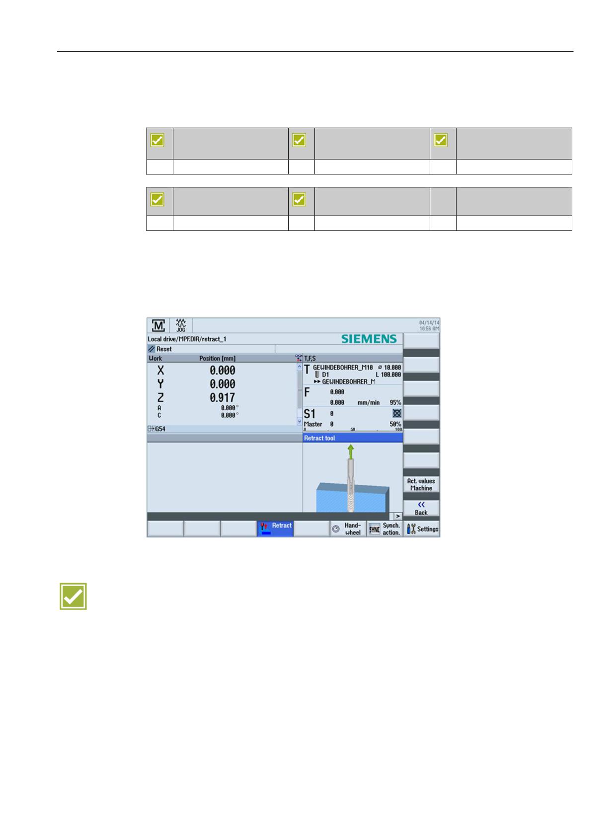
The Retract function supports the manual retraction of the tool after an interruption. In the
JOG mode, after the interruption, the tool can be retracted from the workpiece in the tool
direction.
Typical applications include machining while deploying the CYCLE800 swivel cycle, 5-axis
machining with TRAORI as well as tapping without compensating chuck.
Benefit
Ⴠ Machining can be continued at the point of interruption
SINUMERIK Operate - Milling
Control system overview for machine tools' sales people, 2017, A5E41992599B AA
35

CNC operation in manual mode (JOG)
4.8 Stop and retract (ESR)
4.8
Stop and retract (ESR)
4.8.1
Stop and retract (ESR) - Drive-autonomous
SINUMERIK 828D
SINUMERIK 828D
SINUMERIK 828D
BASIC
ADVANCED
Option: M60
Option: M60
Option: M60
SINUMERIK 840D sl
SINUMERIK 840D sl
BASIC
Option: M60
Option: M60
The extended stop and retract (ESR) function - drive-autonomous offers the possibility of
flexibly responding when a fault situation occurs, irrespective of the higher-level control (NC):
For this purpose, the following axial functions can be configured in the drive:
Ⴠ Retract
Ⴠ Extended stop
Ⴠ Generator operation
The drive-autonomous responses are automatically initiated in fault situations. The triggering
of the drive-autonomous responses can also be realized user-specific via the part programs
or synchronized actions from the higher-level control. As the stopping and retraction motion
of the drive-autonomous ESR are purely axial, in contrast to the control-controlled ESR,
couplings are not taken into account.
Benefit
Ⴠ Faster, situation-conform stop and retraction of axes after a power failure
Ⴠ Stopping and retraction motions in the drives even when they can no longer be specified
from the control, e.g. as a result of a communication failure
Ⴠ Fast resumption of the part program thanks to the block search at the point of interruption
SINUMERIK Operate - Milling
36
Control system overview for machine tools' sales people, 2017, A5E41992599B AA

CNC operation in manual mode (JOG)
4.8 Stop and retract (ESR)
4.8.2
Stop and retract (ESR) - CNC-controlled and drive-autonomous
SINUMERIK 828D
SINUMERIK 828D
SINUMERIK 828D
BASIC
ADVANCED
not available
not available
not available
SINUMERIK 840D sl
SINUMERIK 840D sl
BASIC
Option: M61
Option: M61
As well as the drive-autonomous stop and retract function, the CNC-controlled stop and
retract function is also available. To permit smooth interpolated retraction on the path or
contour, the path interpolation can be processed further for a definable period following the
triggering event.
The retraction axes are subsequently traversed in synchronism to an absolute or incremental
position as programmed. These functions are primarily used for gearing and grinding
technologies.
Benefit
Ⴠ Faster, situation-conform stop and retraction of axes after a power failure
Ⴠ Safe stopping, also of the safety axes
Ⴠ Fast resumption of the part program thanks to the block search at the point of interruption
SINUMERIK Operate - Milling
Control system overview for machine tools' sales people, 2017, A5E41992599B AA
37
CNC operation in manual mode (JOG)
4.9 Swiveling in setup mode
4.9
Swiveling in setup mode
SINUMERIK 828D
SINUMERIK 828D
SINUMERIK 828D
BASIC
ADVANCED
Basic configuration
Basic configuration
Basic configuration
SINUMERIK 840D sl
SINUMERIK 840D sl
BASIC
Basic configuration
Basic configuration
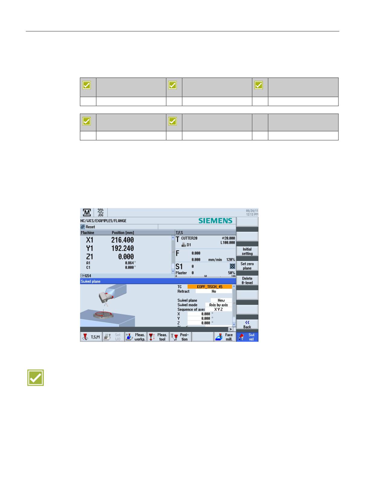
You can swivel the machining plane to any angle in setup mode:
Ⴠ Machining inclined surfaces
Ⴠ Measure with inclined tool or table
The plane can be swiveled directly including rotation of coordinates or axial swiveling. Using
the initial setting softkey, you can traverse the rotary axes of the swivel data set to the initial
position. Here, you can select between with and without retraction.
Benefits
Ⴠ Swivel the machining plane in setup mode by dialog
Ⴠ Simple setup of the workpiece for machining with swivel axes
SINUMERIK Operate - Milling
38
Control system overview for machine tools' sales people, 2017, A5E41992599B AA
CNC operation in manual mode (JOG)
4.10 Manual machine
4.10
Manual machine
SINUMERIK 828D
SINUMERIK 828D
SINUMERIK 828D
BASIC
ADVANCED
Option: P17
Option: P17
Option: P17
SINUMERIK 840D sl
SINUMERIK 840D sl
BASIC
Option: P17
Option: P17
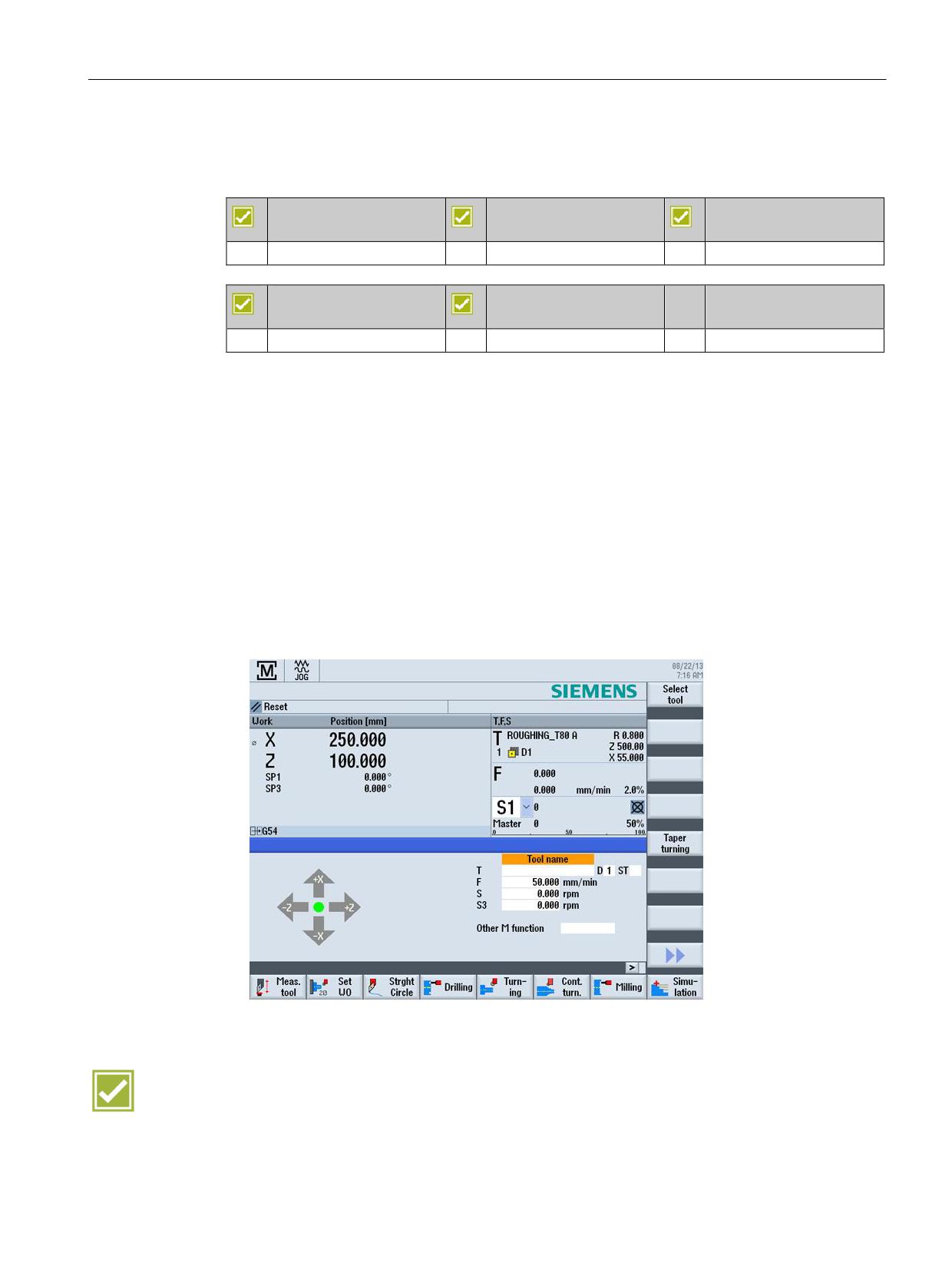
The "Manual machine" function is part of the Shopmill/Shopturn option package. This allows
you to perform all important machining operations in the manual machine operating area
without needing to create a specific part program.
The following functions are available:
Ⴠ Measuring a tool
Ⴠ Traversing axes
Ⴠ Setting the work offset
Ⴠ Turning a straight line / circle
Ⴠ Drilling, including centering, deep-hole drilling, tapping
Ⴠ Milling, including face milling, pocket, multiple edge spigot
Ⴠ Milling contours
Benefit
Ⴠ Simple and intuitive operation of cycle-controlled milling machines
SINUMERIK Operate - Milling
Control system overview for machine tools' sales people, 2017, A5E41992599B AA
39
CNC operation in manual mode (JOG)
4.10 Manual machine
SINUMERIK Operate - Milling
40
Control system overview for machine tools' sales people, 2017, A5E41992599B AA
Tool management
5
5.1
Tool table
SINUMERIK 828D
SINUMERIK 828D
SINUMERIK 828D
BASIC
ADVANCED
Basic configuration
Basic configuration
Basic configuration
SINUMERIK 840D sl
SINUMERIK 840D sl
BASIC
Basic configuration
Basic configuration
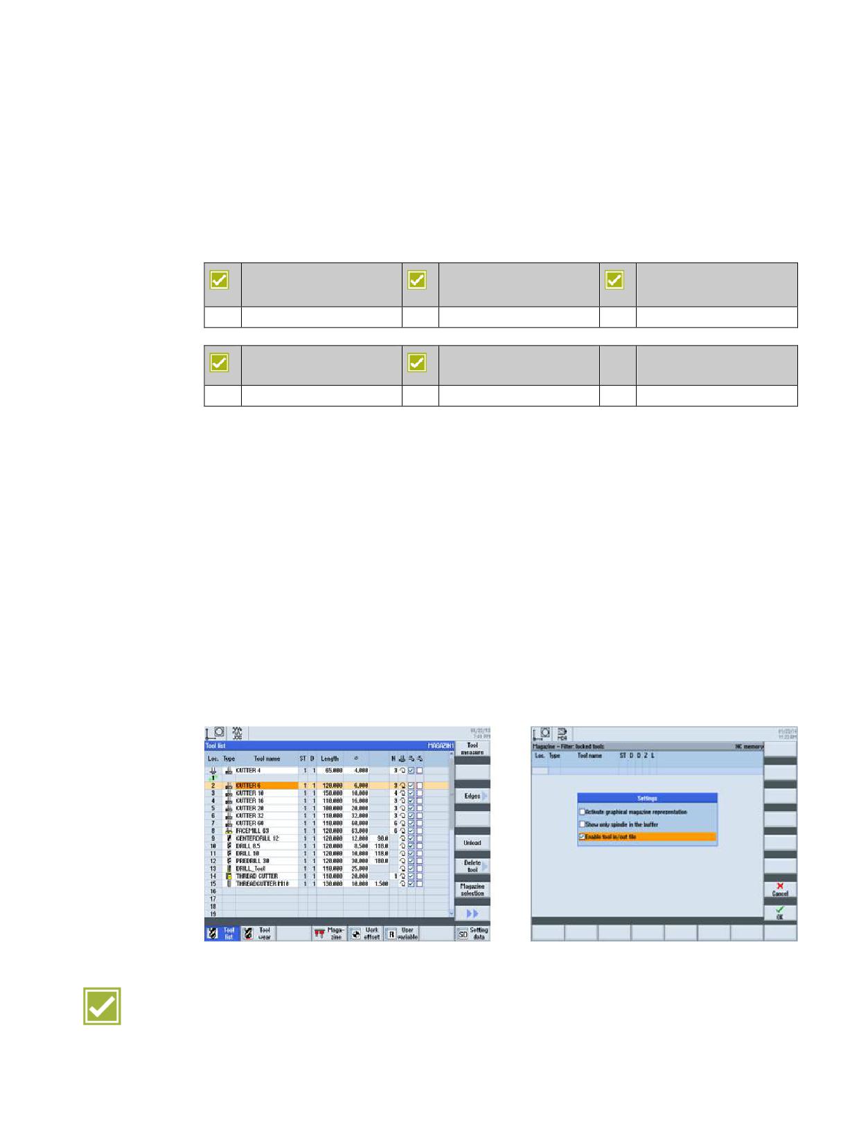
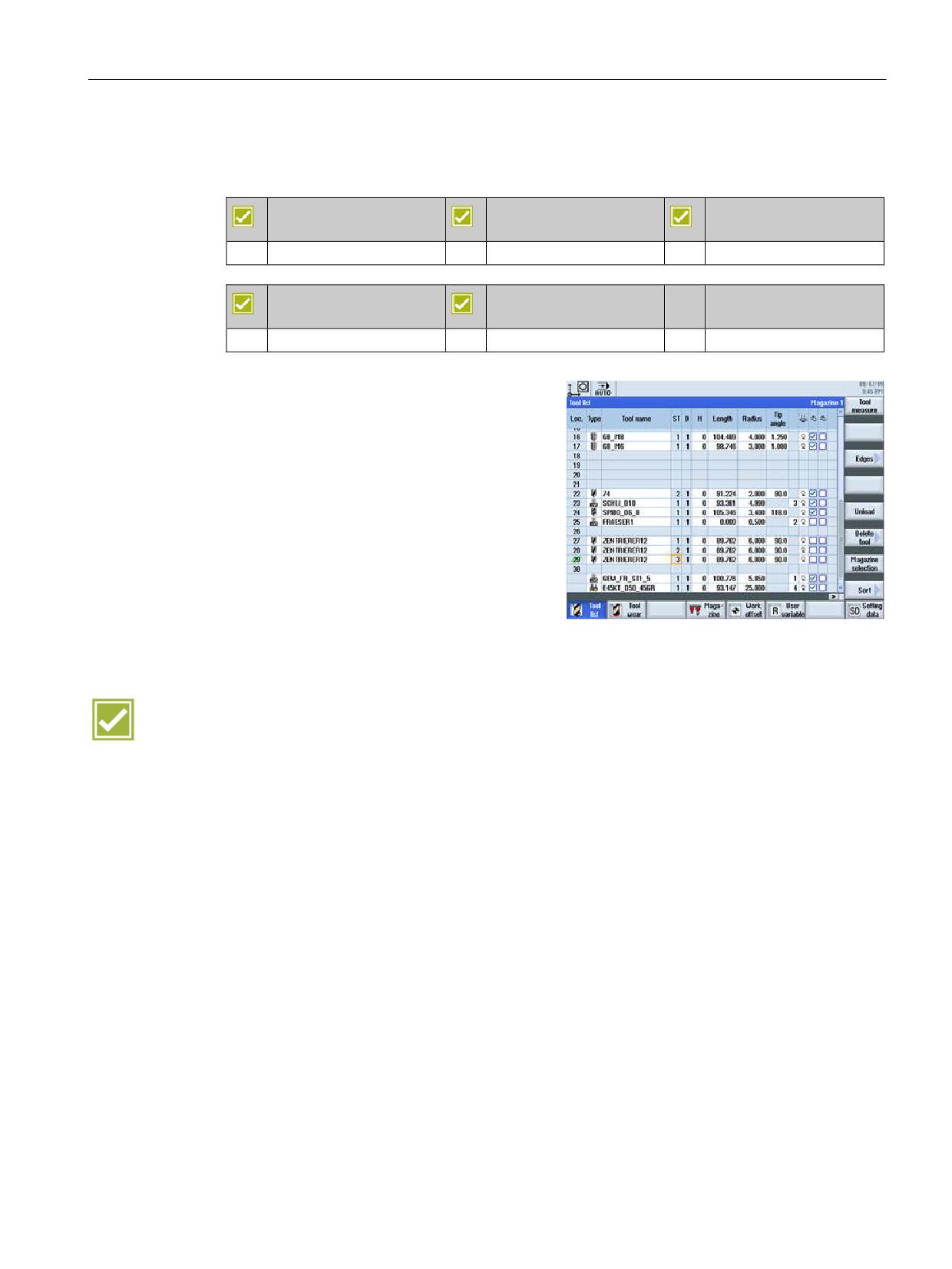
Tools with their complete operating data can be managed in the tool list.
Ⴠ Tools are assigned to the desired magazine locations with the load function.
Ⴠ For each tool, you can store the following data:
- Tool type: e.g. face milling cutter, taps and 3D probes
- Clear tool name in plain text, example: CUTTER_HEAD_63MM
- Max. of 9 cutting edges per tool
- Tool length and diameter
- Nose angle for drills or number of teeth for milling tools
- Spindle direction and coolant (level 1 and 2) and up to four additional functions
Ⴠ Direct transfer of the tool from the list in the program or for measurement
Ⴠ Using the settings, for example, you can activate the graphic magazine display
Ⴠ Reading tools from a file or archiving to a file
Benefits
Ⴠ All tool data at a glance
Ⴠ Simple and secure handling via unmistakable tool names
SINUMERIK Operate - Milling
Control system overview for machine tools' sales people, 2017, A5E41992599B AA
41
Tool management
5.2 Monitoring of tool life and workpiece count
5.2
Monitoring of tool life and workpiece count
SINUMERIK 828D
SINUMERIK 828D
SINUMERIK 828D
BASIC
ADVANCED
Basic configuration
Basic configuration
Basic configuration
SINUMERIK 840D sl
SINUMERIK 840D sl
BASIC
Basic configuration
Basic configuration
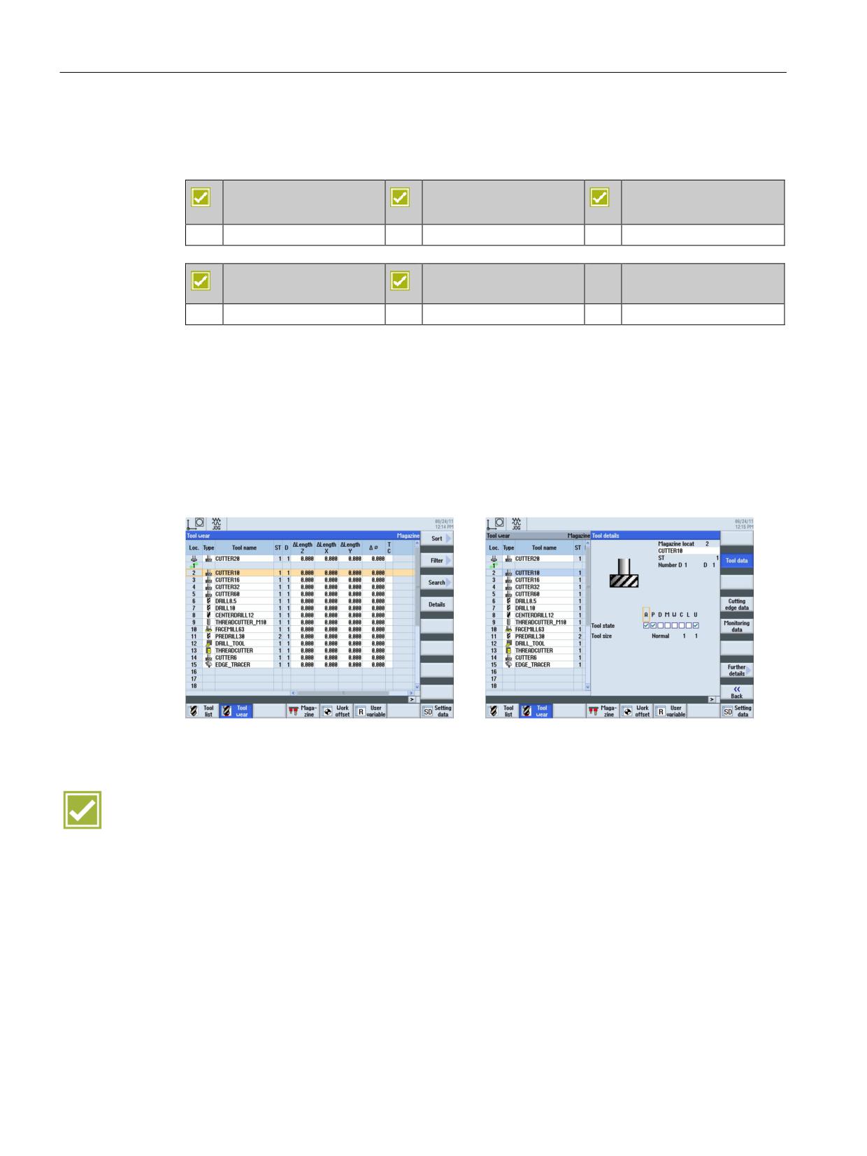
You can use SINUMERIK Operate to monitor the service life of your tools and the number of
exchanges. You can give your tools meaningful names instead of cryptic numbers. You will
come to appreciate this convenience when you read the CNC program, if not before.
Ⴠ Monitor cutting time (T) in minutes or number of exchanges (C)
Ⴠ Prewarning limit for timely preparation of new tools
Ⴠ Provided the desired tool is not in the magazine, SINUMERIK Operate will request a
manual tool change.
Benefits
Ⴠ Reduction of machine standstill times via tool monitoring
Ⴠ Support of tool life monitoring or job time monitoring as standard
SINUMERIK Operate - Milling
42
Control system overview for machine tools' sales people, 2017, A5E41992599B AA
Tool management
5.3 Replacement tools
5.3
Replacement tools
SINUMERIK 828D
SINUMERIK 828D
SINUMERIK 828D
BASIC
ADVANCED
Option: M78
Option: M78
Basic configuration
SINUMERIK 840D sl
SINUMERIK 840D sl
BASIC
Basic configuration
Basic configuration
If needed, you can also manage replacement
tools with SINUMERIK Operate. Tools with
the same name are created as replacement
tools. Replacement tools are identified with an
increasing number in the ST column.
Benefit
Ⴠ Automatic exchange of identical tools for unmanned operation
SINUMERIK Operate - Milling
Control system overview for machine tools' sales people, 2017, A5E41992599B AA
43
Data memory
6
6.1
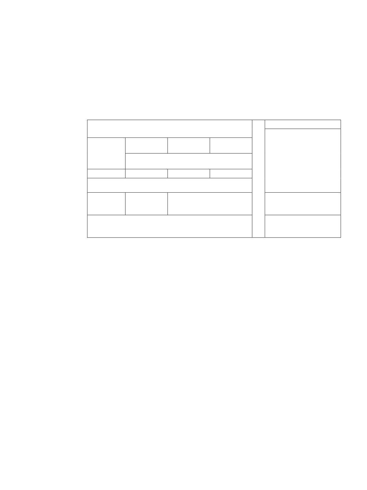
Data storage - SINUMERIK 828D
Internal memory
External storage
Execution from external
storage (EES)
828D
828D
828D
(option P75)
BASIC
ADVANCED
Network, USB storage me-
USB / CF card can be used for data transport or
dia, compact flashcard
for execution with EXTCALL
Option P77
100 MB
SW
3 MB
5 - 10 MB
Execution from the CNC
expanded user memory
(option P77)
Internal memory can be expanded via option P77 ൺ 100 MB
External storage via
option P75 ൺ can be ex-
panded almost without limit
SINUMERIK Operate - Milling
Control system overview for machine tools' sales people, 2017, A5E41992599B AA
45
Data memory
6.2 Data storage - SINUMERIK 840D sl
6.2
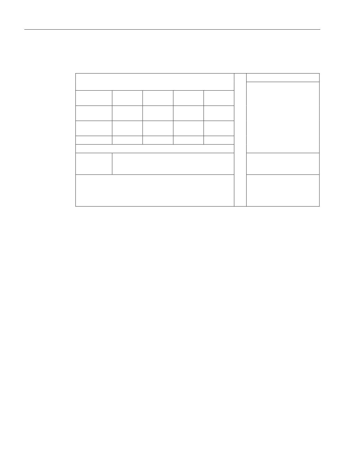
Data storage - SINUMERIK 840D sl
Internal memory
External storage
Execution from external
storage devices (EES, op-
NCU
NCU
NCU
NCU +
tion P75)
PCU
Network, USB storage me-
Option P77 +
up to
dia, compact flashcard
PCU
40 GB
Option P77 +
up to 6 GB
option P12 1)
Option P77
100 MB
CNC user
NCU 710.3B: 2 to 16 MB
Execution from the CNC
memory
expanded user memory
NCU 720.3B and NCU 730.3B: 2 to 22 MB
(option D00)
(option P77)
Internal memory can be expanded via option P77 + PCU ൺ
External storage via
40 GB
option P75 ൺ can be ex-
panded almost without limit
Internal memory can be expanded via option P77 + P12 ൺ 6 GB
Internal memory can be expanded via option P77 ൺ 100 MB
1) HMI user memory, alternative to PCU
SINUMERIK Operate - Milling
46
Control system overview for machine tools' sales people, 2017, A5E41992599B AA
Data transfer
7
7.1
Program Manager
SINUMERIK 828D
SINUMERIK 828D
SINUMERIK 828D
BASIC
ADVANCED
Basic configuration
Basic configuration
Basic configuration
SINUMERIK 840D sl
SINUMERIK 840D sl
BASIC
Basic configuration
Basic configuration
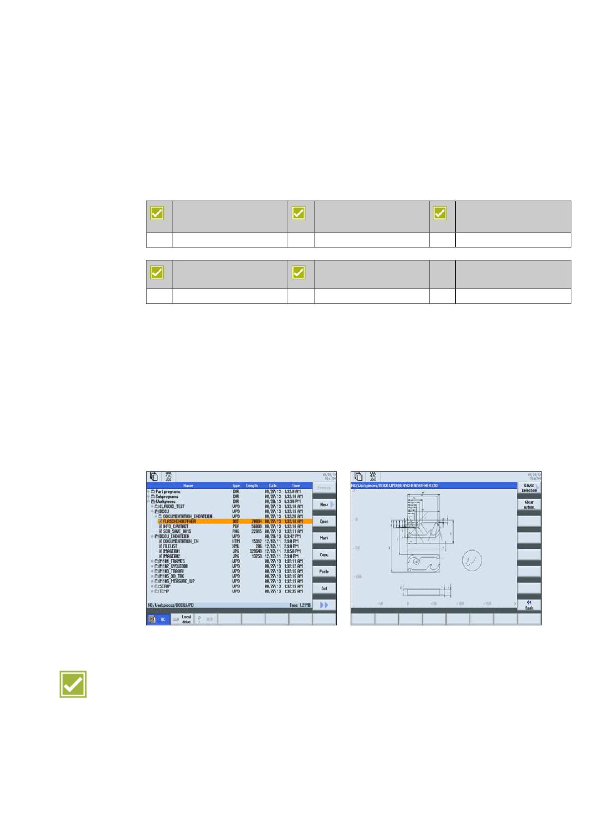
The program manager provides an optimum overview of the directories and programs, and
very easy-to-use file handling similar to Windows Explorer.
Ⴠ Plain names with as many as 24 characters for directories and files
Ⴠ Manage subdirectories on external storage media, local drives and on the NC
Ⴠ Store and display files of any type (e.g. *.png, *.pdf, *.dxf, *.xml)
Ⴠ Manage and open DXF files
Ⴠ Display all storage media in the program manager (with details of the storage capacity),
including the network drives.
Ⴠ Edit part programs on all media
Highlights
Ⴠ Easy and open exchange of data between the various storage media and the network
Ⴠ User-friendly data handling in typical PC style with copy, paste, rename, etc.
Ⴠ Preview window permits quick identification of programs without having to open them
SINUMERIK Operate - Milling
Control system overview for machine tools' sales people, 2017, A5E41992599B AA
47

Data transfer
7.2 Ethernet networking
7.2
Ethernet networking
SINUMERIK 828D
SINUMERIK 828D
SINUMERIK 828D
BASIC
ADVANCED
Option: P01
Option: P01
Option: P01
SINUMERIK 840D sl
SINUMERIK 840D sl
BASIC
Basic configuration
Basic configuration
The SINUMERIK controls are prepared for networking via Ethernet (TCP/IP) (RJ45
connection).
Ⴠ The data transfer rate is 10/100 Mbps.
Ⴠ Remote access to the control via the RCS Commander, e.g. for commissioning and
remote diagnostics
Ⴠ Access to the network drives is available directly from the program manager. No
additional software is required on the server.
Highlight
Ⴠ Easy and economical connection via Ethernet (TCP/IP) to Windows PCs
Ⴠ No software needs to be installed on the servers
SINUMERIK Operate - Milling
48
Control system overview for machine tools' sales people, 2017, A5E41992599B AA

CNC operation in automatic mode (AUTO)
8
8.1
Block search
SINUMERIK 828D
SINUMERIK 828D
SINUMERIK 828D
BASIC
ADVANCED
Basic configuration
Basic configuration
Basic configuration
SINUMERIK 840D sl
SINUMERIK 840D sl
BASIC
Basic configuration
Basic configuration
A block search may be executed in machine status RESET, e.g. after a program interruption
or to specifically return to machining. The program data is prepared in such a way that all
relevant parameters (tool, work offsets, M functions, etc.) are available when accessing the
program.
The following search variants are available:
Ⴠ specifically to the point of interruption, also possible after power off
Ⴠ to any CNC block in DIN/ISO programs
Ⴠ to any subprogram levels in DIN/ISO programs
Ⴠ in ShopMill machining step programs
Ⴠ in position patterns for machining step programming
Ⴠ accelerated block search in large mold making programs
You can individually configure the block search:
Ⴠ with calculation / without calculation
Ⴠ with approach / without approach
Benefits
Ⴠ Time-saving and secure restart at any program point, as no editing of the part program is
required
Ⴠ An extremely quick block search is also available for large part programs through the
"External block search without calculation" function; overstore, if necessary
SINUMERIK Operate - Milling
Control system overview for machine tools' sales people, 2017, A5E41992599B AA
49

CNC operation in automatic mode (AUTO)
8.2 Program control
8.2
Program control
SINUMERIK 828D
SINUMERIK 828D
SINUMERIK 828D
BASIC
ADVANCED
Basic configuration
Basic configuration
Basic configuration
SINUMERIK 840D sl
SINUMERIK 840D sl
BASIC
Basic configuration
Basic configuration
You can influence the program sequence in the AUTO and MDI modes. The following
options are available to do this:
Ⴠ
PRT - no axis motion
The program is completely executed with the axes stationary, e.g. for the program test.
Ⴠ
DRY - dry run feedrate
The traversing velocities programmed in conjunction with G1, G2, G3, CIP and CT are
replaced by a defined dry run feedrate.
Ⴠ
RG0 - reduced rapid traverse
You define the reduced rapid traverse in the settings for automatic operation.
Ⴠ
M01 - programmed stop 1
The processing of the program stops at every block in which supplementary function M01
is programmed. In this way you can check the intermediate result
when machining a workpiece.
Ⴠ
DRF - handwheel offset
This selection allows you to enter an additional incremental work offset while processing
in automatic mode with an electronic handwheel.
Ⴠ
SKP
Skip blocks are skipped during machining.
Ⴠ
MRD
The display of the measurement result can be enabled or disabled during program
execution.
Benefits
Ⴠ
Secure positioning of new part programs
Ⴠ
Continue machining quickly after interruptions
SINUMERIK Operate - Milling
50
Control system overview for machine tools' sales people, 2017, A5E41992599B AA

CNC operation in automatic mode (AUTO)
8.3 Execution from external storage devices
8.3
Execution from external storage devices
SINUMERIK 828D
SINUMERIK 828D
SINUMERIK 828D
BASIC
ADVANCED
Basic configuration
Basic configuration
Basic configuration
SINUMERIK 840D sl
SINUMERIK 840D sl
BASIC
Basic configuration
Basic configuration
You can select, edit and execute part programs directly on the CF card, USB stick, hard disk
or via the network.
SINUMERIK 828D
SINUMERIK 828D
SINUMERIK 828D
BASIC
ADVANCED
Option: P75
Option: P75
Option: P75
SINUMERIK 840D sl
SINUMERIK 840D sl
BASIC
Option: P75
Option: P75
The "Execution from external storage (EES)" option provides the following advantages over
the basic configuration:
Ⴠ Uniform syntax for the subprogram call, independent of the storage location of the
subprogram. This reduces syntax errors for the subprogram call.
Ⴠ Part programs can be edited without NC reset.
Ⴠ The size of the memory available on the machine can be expanded economically with
external media. The size of the part programs is limited only by the capacity of the
external data storage.
Benefit
Ⴠ Quick and easy access to part programs on external storage media
SINUMERIK Operate - Milling
Control system overview for machine tools' sales people, 2017, A5E41992599B AA
51
CNC operation in automatic mode (AUTO)
8.4 Basic block display
8.4
Basic block display
SINUMERIK 828D
SINUMERIK 828D
SINUMERIK 828D
BASIC
ADVANCED
Basic configuration
Basic configuration
Basic configuration
SINUMERIK 840D sl
SINUMERIK 840D sl
BASIC
Basic configuration
Basic configuration
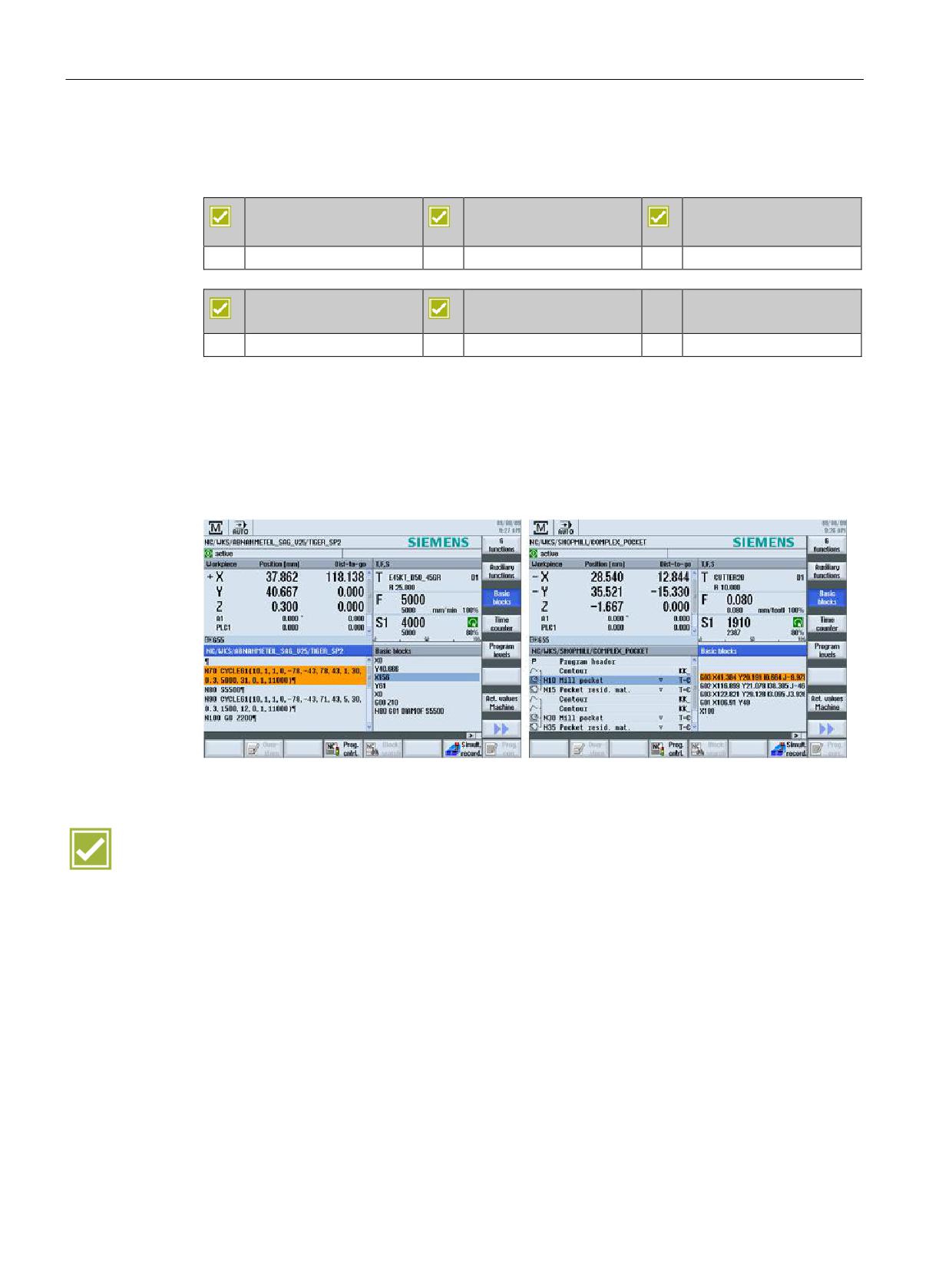
The individual traversing blocks are displayed as DIN/ISO commands during execution of
machining steps or machining cycles.
The basic block display guarantees an especially high process security while running-in
programs in single block mode.
This function is available to you for programGUIDE (screenshot on left) and also for ShopMill
(screenshot on right).
Benefit
Ⴠ Optimal control of the program execution, also in complex sequences or machining
cycles, especially in single block mode
SINUMERIK Operate - Milling
52
Control system overview for machine tools' sales people, 2017, A5E41992599B AA
CNC operation in automatic mode (AUTO)
8.5 Simultaneous recording
8.5
Simultaneous recording
SINUMERIK 828D
SINUMERIK 828D
SINUMERIK 828D
BASIC
ADVANCED
Option: P22
Option: P22
Option: P22
SINUMERIK 840D sl
SINUMERIK 840D sl
BASIC
Option: P22
Option: P22
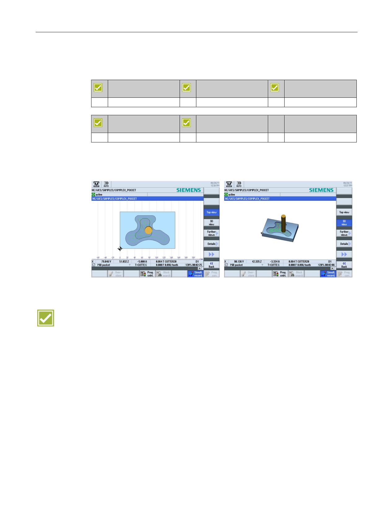
While machining the workpiece the tool paths can be recorded on the screen of the control in
the plan view, 3-side view or in 3D view. Workpiece depiction and views correspond to the
graphic simulation.
Benefit
Ⴠ Machining can also be monitored in a complex machine room
SINUMERIK Operate - Milling
Control system overview for machine tools' sales people, 2017, A5E41992599B AA
53
CNC operation in automatic mode (AUTO)
8.6 Logging measurement results in automatic operation
8.6
Logging measurement results in automatic operation
SINUMERIK 828D
SINUMERIK 828D
SINUMERIK 828D
BASIC
ADVANCED
Basic configuration
Basic configuration
Basic configuration
SINUMERIK 840D sl
SINUMERIK 840D sl
BASIC
Basic configuration
Basic configuration
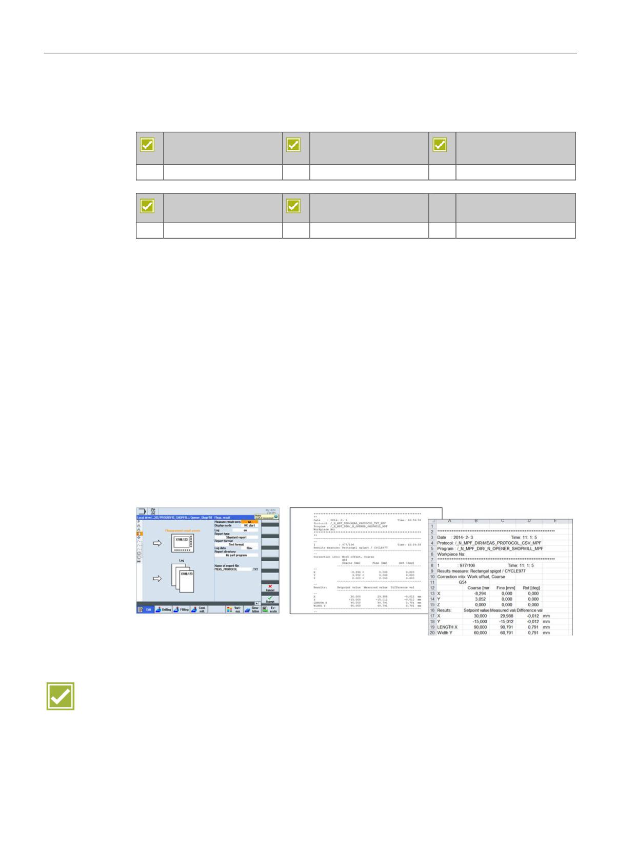
In automatic operation, you can output the measurement results as measuring log. You can
configure the output. The following settings are some of those possible:
Ⴠ Display mode: autom. 8 s, NC start, for alarm
Ⴠ Log type: standard log, user log
Ⴠ Log format: text format (*.txt), table format (*.csv)
Ⴠ Log data: new (discard old log data), append (append to old log data)
Ⴠ Log storage: storage directory (complete path)
You can then open the measuring log in the program management at the configured storage
path. The measuring log contains data that includes:
Ⴠ Date and time when the log was written
Ⴠ Measuring method
Ⴠ Correction target
Ⴠ Setpoints, measured values and differences
Note: Irrespective of the user interface language, the measuring logs are output in English.
Benefit
Ⴠ Simple logging of measured values in log files
SINUMERIK Operate - Milling
54
Control system overview for machine tools' sales people, 2017, A5E41992599B AA
CNC operation in automatic mode (AUTO)
8.7 Handwheel override
8.7
Handwheel override
SINUMERIK 828D
SINUMERIK 828D
SINUMERIK 828D
BASIC
ADVANCED
Basic configuration
Basic configuration
Basic configuration
SINUMERIK 840D sl
SINUMERIK 840D sl
BASIC
Basic configuration
Basic configuration
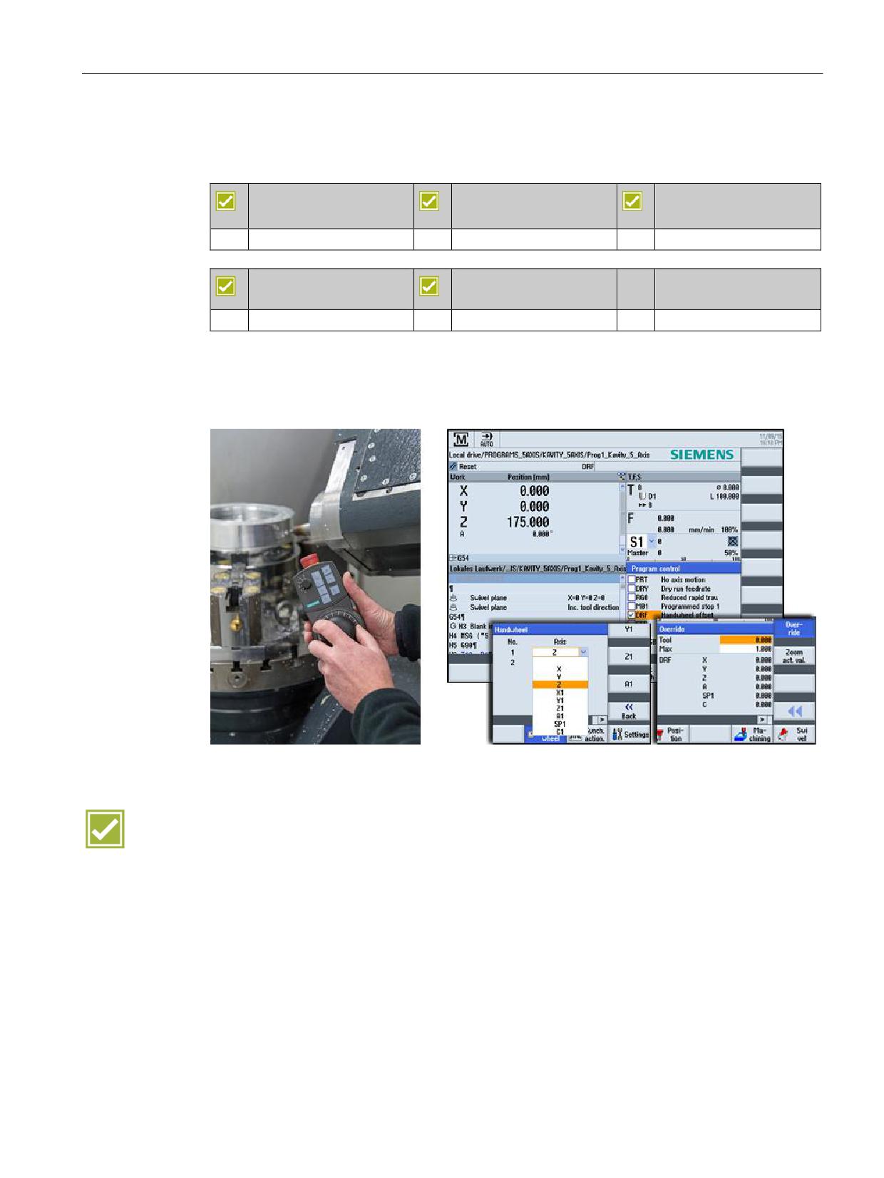
In the AUTOMATIC mode, while executing a program, small corrections and override feed of
the tool in the tool direction are possible using a handwheel. When the orientation of the tool
changes, the handwheel override that has been accumulated is also rotated. The manual
correction acts in the form of override to the traversing motion from the NC program.
Benefit
Ⴠ Small corrections and feeds of the tool in the tool direction are possible using a
handwheel.
SINUMERIK Operate - Milling
Control system overview for machine tools' sales people, 2017, A5E41992599B AA
55
CNC operation in automatic mode (AUTO)
8.7 Handwheel override
SINUMERIK Operate - Milling
56
Control system overview for machine tools' sales people, 2017, A5E41992599B AA
CNC functions
9
9.1
80-bit NANO floating-point accuracy
SINUMERIK 828D
SINUMERIK 828D
SINUMERIK 828D
BASIC
ADVANCED
Basic configuration
Basic configuration
Basic configuration
SINUMERIK 840D sl
SINUMERIK 840D sl
BASIC
Basic configuration
Basic configuration
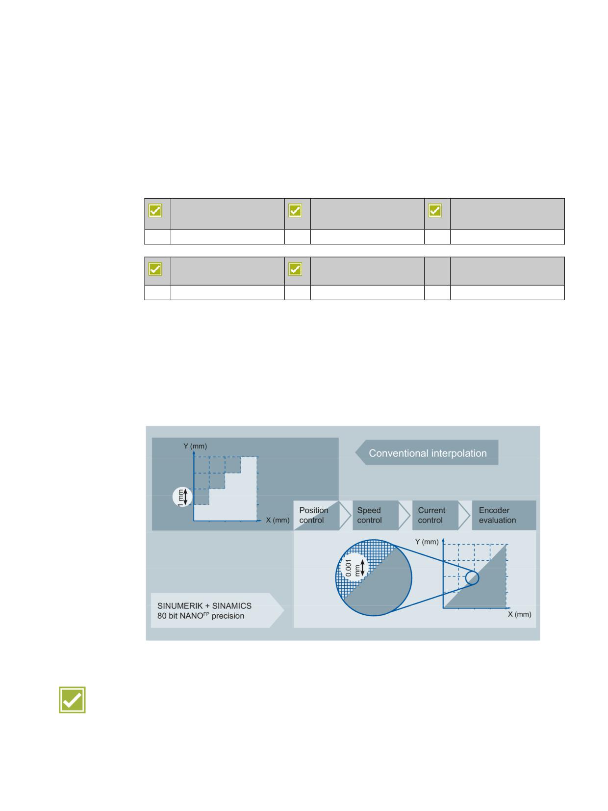
The accuracy of the workpiece is determined by more factors than just the mechanical
characteristics of the machine. The CNC also contributes to a critical degree towards the
precision of the workpieces. SINUMERIK Operate offers many CNC functions for this
purpose.
The SINUMERIK controls and the SINAMICS drive calculate with 80-bit NANO floating-point
accuracy. This enables a calculation accuracy much less than a nanometer. This exactness
is available not only for closed loop position control but also for closed-loop power and speed
control and also for sensor evaluation of the drive.
Benefit
Ⴠ Maximum precision in the workpiece results based on extremely high calculation
accuracy
SINUMERIK Operate - Milling
Control system overview for machine tools' sales people, 2017, A5E41992599B AA
57

CNC functions
9.2 Block change times
9.2
Block change times
9.2.1
SINUMERIK 828D
SINUMERIK 828D
SINUMERIK 828D
SINUMERIK 828D
BASIC
ADVANCED
Basic configuration
Basic configuration
Basic configuration
The following table shows typical block change times depending on the deployed PPU:
PPU 241.3/240.3
PPU 281.3/280.3
PPU 290.3
SW24
SW26
SW28
SW28
~3 ms
~2 ms
~1 ms
~1 ms
Benefit
Ⴠ Minimum block change times for the associated performance versions
9.2.2
SINUMERIK 840D sl
SINUMERIK 840D sl
SINUMERIK 840D sl
BASIC
Basic configuration
Basic configuration
The following table shows typical block change times depending on the deployed NCU:
NCU 710.3B PN
NCU 720.3B PN
NCU 730.3B PN
1.2 ms
0.5 ms
0.3 ms
Benefit
Ⴠ Minimum block change times for the associated performance versions
SINUMERIK Operate - Milling
58
Control system overview for machine tools' sales people, 2017, A5E41992599B AA
CNC functions
9.3 Jerk limiting
9.3
Jerk limiting
SINUMERIK 828D
SINUMERIK 828D
SINUMERIK 828D
BASIC
ADVANCED
Basic configuration
Basic configuration
Basic configuration
SINUMERIK 840D sl
SINUMERIK 840D sl
BASIC
Basic configuration
Basic configuration
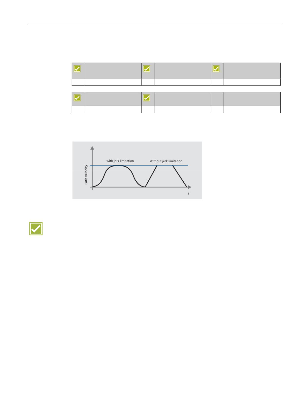
The control calculates a steady acceleration profile instead of jumps in acceleration. This
enables jerk-free speed characteristics for the involved path axes. The jerk limitation can
also be directly activated in the part program with the »SOFT« NC language command.
Benefits
Ⴠ Longer machine lifespan through protection of the mechanical components
Ⴠ Higher path accuracy through softer acceleration
SINUMERIK Operate - Milling
Control system overview for machine tools' sales people, 2017, A5E41992599B AA
59
CNC functions
9.4 Dynamic feedforward control
9.4
Dynamic feedforward control
SINUMERIK 828D
SINUMERIK 828D
SINUMERIK 828D
BASIC
ADVANCED
Basic configuration
Basic configuration
Basic configuration
SINUMERIK 840D sl
SINUMERIK 840D sl
BASIC
Basic configuration
Basic configuration
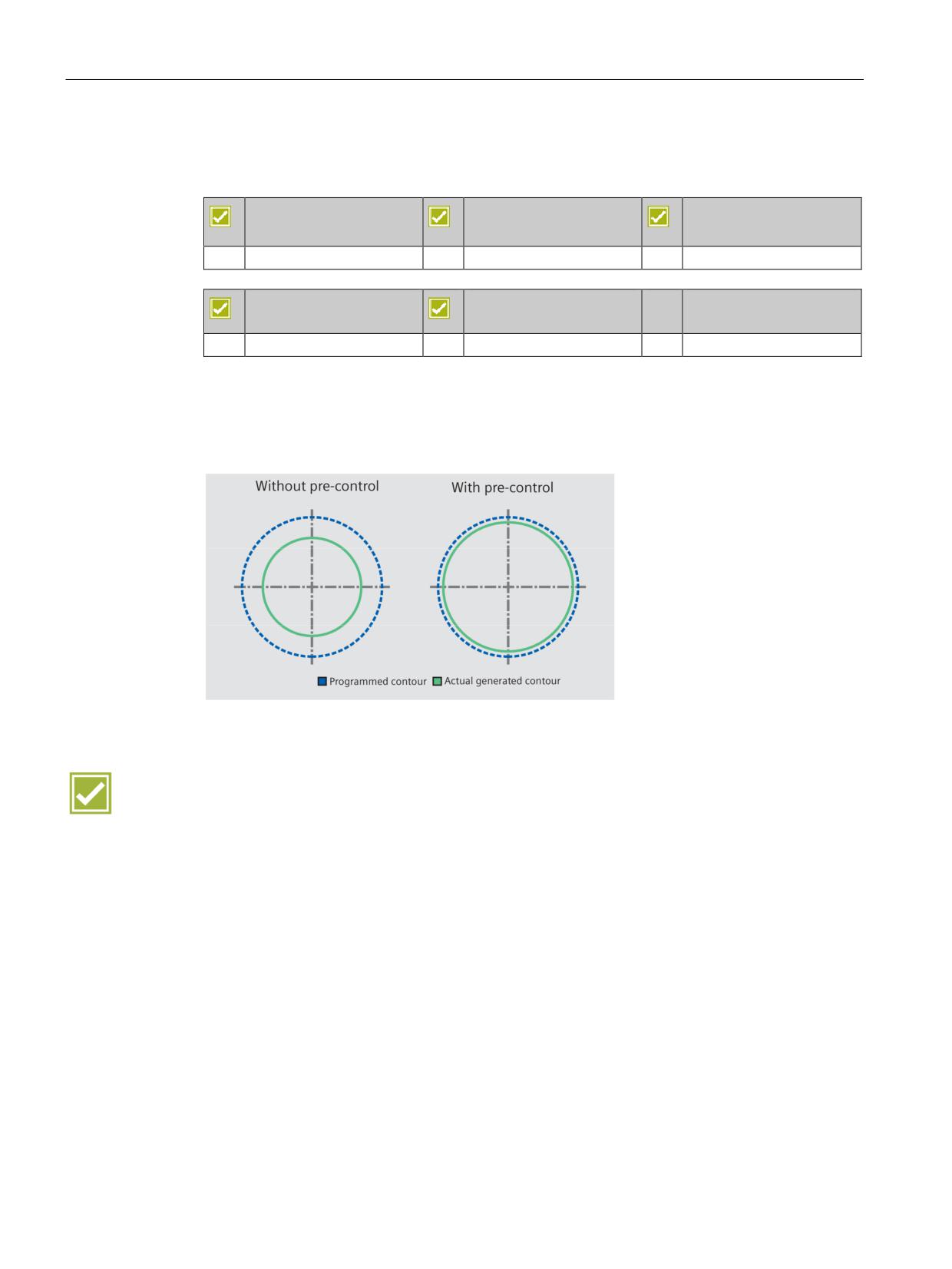
Inaccuracies in the resulting workpiece contour due to following errors can practically be
eliminated using dynamic feedforward control FFWON. The result is excellent machining
precision even at high path speeds. This is clarified with a circularity test on the machine.
Example:
Benefit
Ⴠ Higher path accuracy through compensation of contouring errors
SINUMERIK Operate - Milling
60
Control system overview for machine tools' sales people, 2017, A5E41992599B AA
Tool and mold making
10
10.1
High speed settings
SINUMERIK 828D
SINUMERIK 828D
SINUMERIK 828D
BASIC
ADVANCED
Basic configuration
Basic configuration
Basic configuration
SINUMERIK 840D sl
SINUMERIK 840D sl
BASIC
Basic configuration
Basic configuration
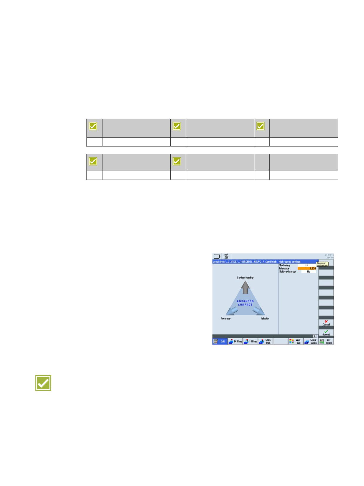
The high speed settings cycle enables easy parameterization of the optimum motion control
in relation to the machining type and the part program contour tolerance band.
The high-speed setting cycle sets automatically the associated optimum combination of
accuracy, speed and surface quality - for 3-axis and 5-axis machining of free form surfaces.
The cycle is called within the DIN/ISO editor or in ShopMill. Calling this function activates
Advanced Surface and/or Top Surface depending on the options and the configuration. The
best available mold making function is automatically used.
The following settings are possible:
x Machining type
- Roughing
- Rough-finishing
- Finishing
x Tolerance
x Multiple axis program yes/no
x Orientation tolerance and rotary axis
tolerance
Highlight
Ⴠ Simple and easily understandable parameterization of the required machining type
(roughing, pre-finishing or finishing) with an interactive screen
SINUMERIK Operate - Milling
Control system overview for machine tools' sales people, 2017, A5E41992599B AA
61
Tool and mold making
10.2 Advanced Surface and Top Surface
10.2
Advanced Surface and Top Surface
Machining of free-form surfaces involves high requirements regarding speed, precision and
surface quality. The "High Speed Settings" cycle simplifies the parameterization of mold
making applications.
The "Advanced Surface" and "Top Surface" options allow the manufacturing of high-quality
mold making workpieces.
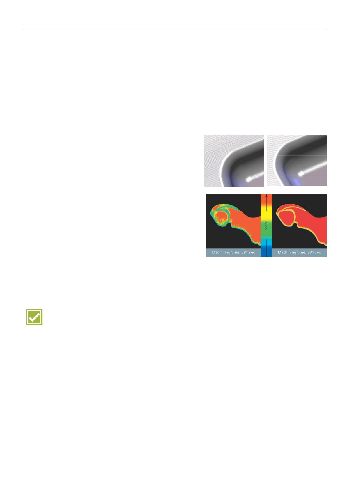
Perfect surface
Conventional CNC
with Advanced Surface
SINUMERIK Operate can even cope with
and Top Surface
inadequate CNC block sequences in mold
making programs: New forward-thinking,
mathematical algorithms perform fully identi-
cal calculations for the movement paths in
forward and reverse directions. This means
that reverse paths on molds yield mirror-finish
workpiece surfaces.
Minimum machining time
In addition, Advanced Surface and Top Sur-
face ensure shortest machining times. A
brand new type of motion control calculates
an ideally smooth surface, for which it keeps
the tool within the optimum speed range at all
times.
One-off optimization
The Advanced Surface and Top Surface algo-
rithms guarantee optimum workpiece surfaces
and shortest machining times after just a sin-
gle optimization of the system.
Highlight
Ⴠ Advanced Surface and Top Surface are synonyms for milling at physical machine limits;
coupled with maximum speed, accuracy and best surface quality, not only for mold
making
SINUMERIK Operate - Milling
62
Control system overview for machine tools' sales people, 2017, A5E41992599B AA
Tool and mold making
10.2 Advanced Surface and Top Surface
10.2.1
Advanced Surface
SINUMERIK 828D
SINUMERIK 828D
SINUMERIK 828D
BASIC
ADVANCED
Basic configuration
Basic configuration
Basic configuration
SINUMERIK 840D sl
SINUMERIK 840D sl
BASIC
Option: S07
Option: S07
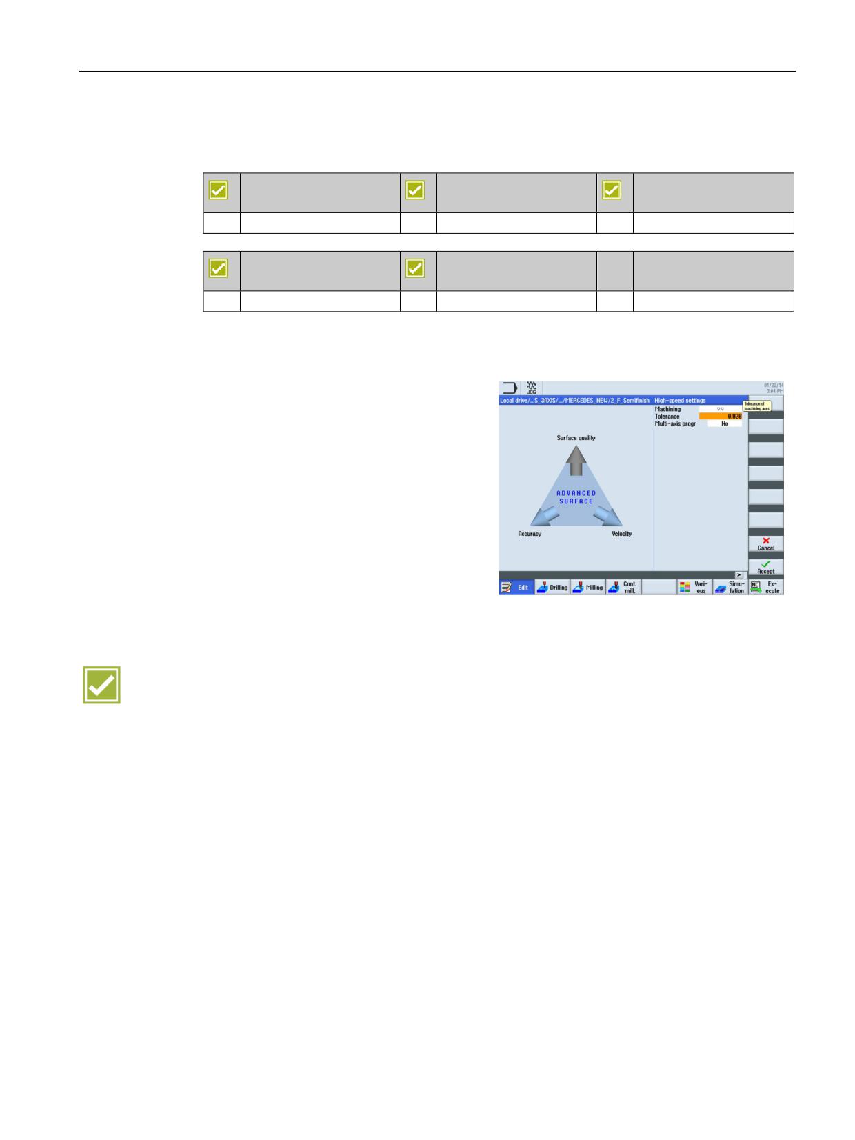
With Advanced Surface you can easily parameterize optimum speed control depending on
the machining type (roughing, rough-finishing, finishing).
Enter the following settings for Advanced Sur-
face:
x Tolerance of the machining axes
x Machining type
- Finishing
- Rough-finishing
- Roughing
- Deselection
x Multiple axis program yes/no
Benefit
Ⴠ Advanced Surface permits maximum productivity coupled with simple process
parameterization - from 3-axis multipass milling through to dynamic 5-axis machining
SINUMERIK Operate - Milling
Control system overview for machine tools' sales people, 2017, A5E41992599B AA
63
Tool and mold making
10.2 Advanced Surface and Top Surface
10.2.2
Top Surface
SINUMERIK 828D
SINUMERIK 828D
SINUMERIK 828D
BASIC
ADVANCED
not available
Option: S17
Option: S17
SINUMERIK 840D sl
SINUMERIK 840D sl
BASIC
Option: S17
Option: S17
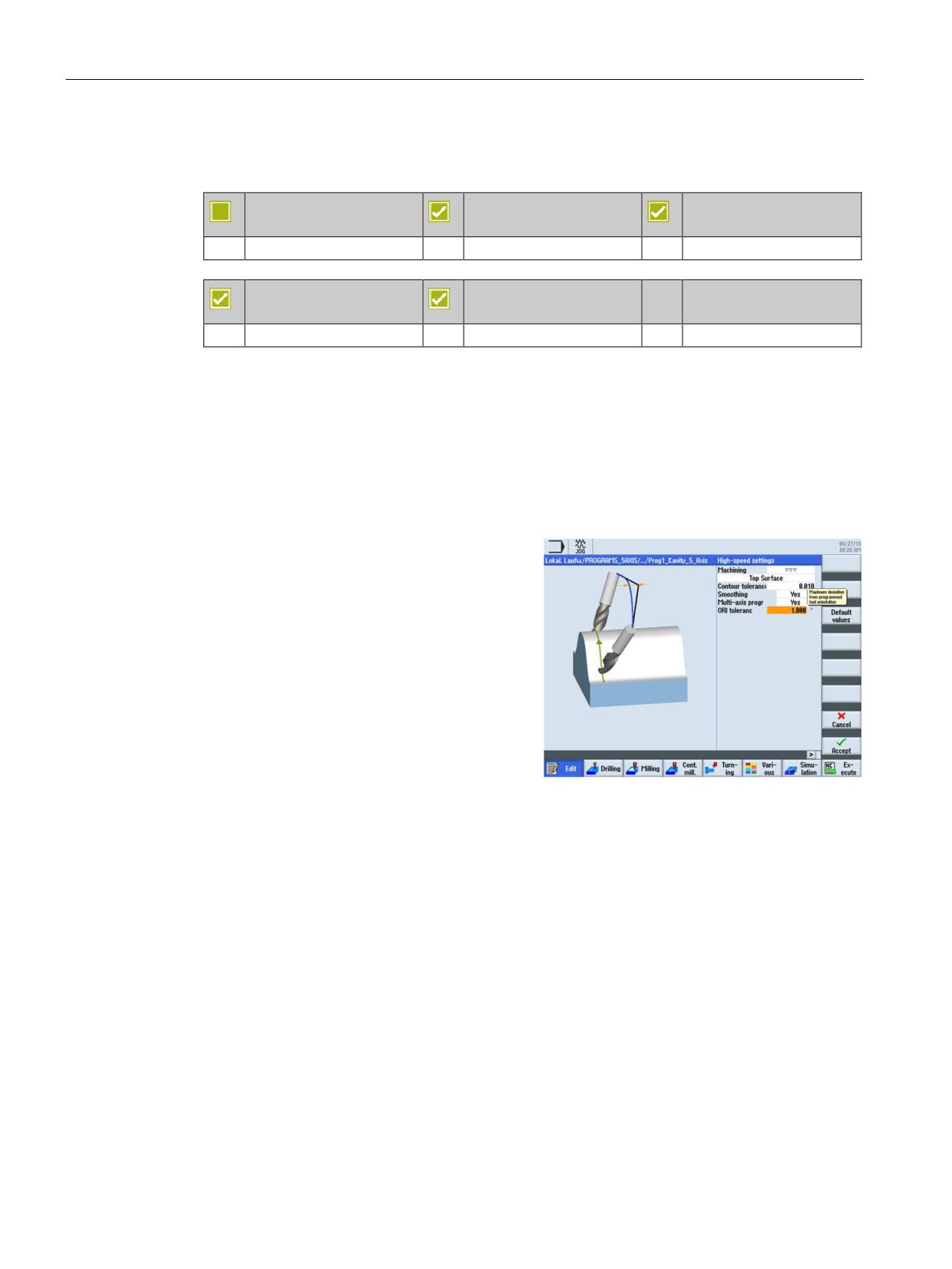
The High Speed Settings cycle, Top Surface option ensures a significantly improved
workpiece surface for inclined multipass finishing programs, even for poor data quality and/or
irregular point distribution in NC programs from the CAD/CAM system.
The dynamic response is also optimized:
Ⴠ Improved observance of the acceleration and jerk limits
Ⴠ Lower vibration excitation of the machine
In addition to selecting the machining types
(finishing, rough-finishing, roughing), the fol-
lowing settings are possible:
x Smoothing yes/no
x Multiple axis program yes/no
x Contour and orientation tolerance
SINUMERIK Operate - Milling
64
Control system overview for machine tools' sales people, 2017, A5E41992599B AA
Tool and mold making
10.2 Advanced Surface and Top Surface
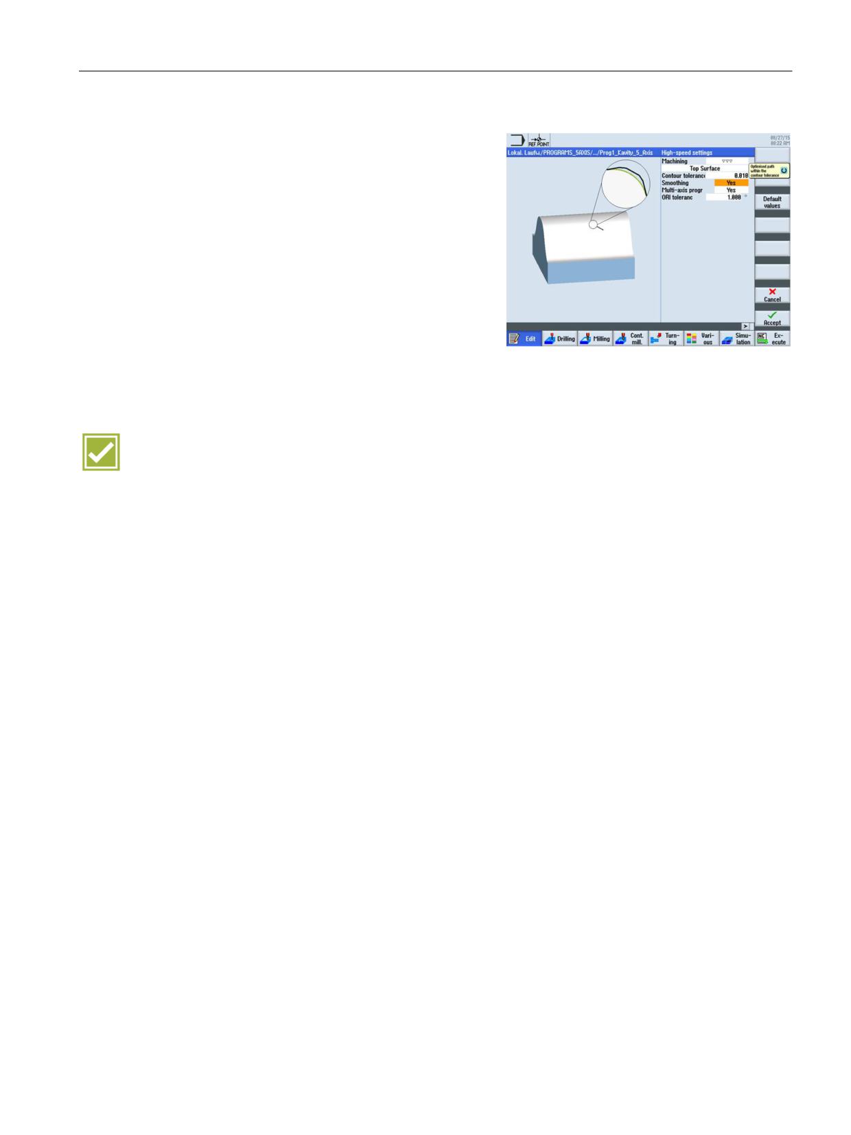
The contour tolerance is shown as magnifying
glass.
Standard values:
x Roughing 0.1
x Rough-finishing 0.05
x Finishing 0.01
The smoothing is also shown in the magnify-
ing glass:
x Smoothing adds shine to the surface.
x Without smoothing, high-precision
contours appear perfectly.
Benefits
Ⴠ Perfect surface quality - Correction of irregularities from the CAD/CAM data, direction-
independent identical smoothing of the milling paths
Ⴠ High accuracy
Ⴠ Stable milling machine - significantly smoother machine running, less wear, long-term
availability
Ⴠ Perfect usability - simple and graphical operator screens, optimum surface quality, even
with the default setting, for most programs
SINUMERIK Operate - Milling
Control system overview for machine tools' sales people, 2017, A5E41992599B AA
65
Tool and mold making
10.3 Look Ahead
10.3
Look Ahead
SINUMERIK 828D
SINUMERIK 828D
SINUMERIK 828D
BASIC
ADVANCED
Basic configuration
Basic configuration
Basic configuration
SINUMERIK 840D sl
SINUMERIK 840D sl
BASIC
Option: S07
Option: S07
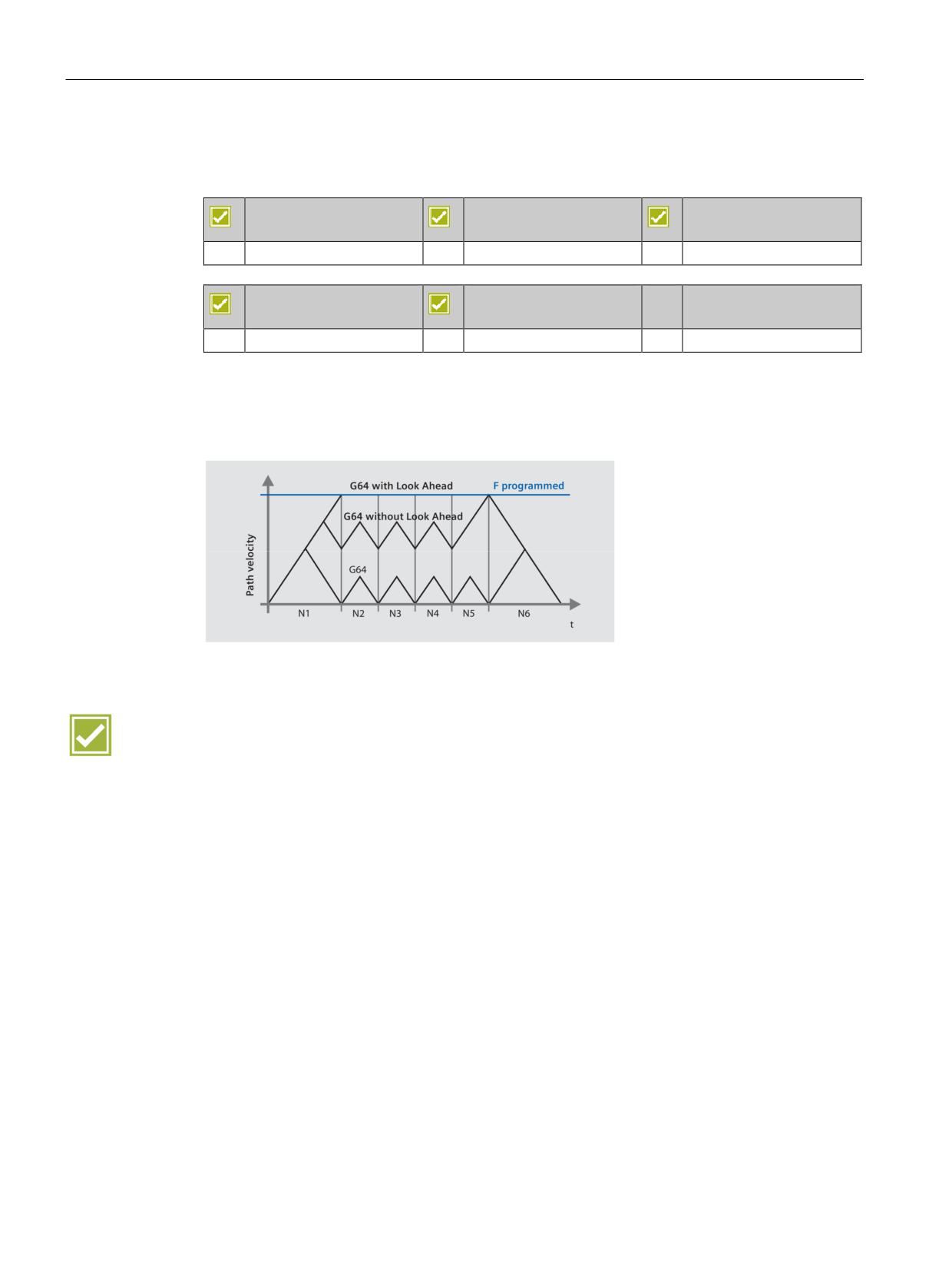
The Look Ahead function (the function is part of Advanced Surface) achieves an optimum
machining speed by looking ahead over a parameterized number of traversing blocks. With
tangential block transitions, the axis is accelerated and decelerated beyond block
boundaries, so that no drops in speed occur.
Highlight
Ⴠ Shorter machining times through optimum speed control
SINUMERIK Operate - Milling
66
Control system overview for machine tools' sales people, 2017, A5E41992599B AA
CNC programming methods
11
SINUMERIK Operate provides the following programming methods for selection:
DIN-ISO programming with programGUIDE
CNC text editor with programGuide cycle support, and DIN-ISO and readable CNC high-
level language commands for mid-sized and large series
The wide choice of technology cycles and the ease of parameterization allows you to reduce
the programming time.
ShopMill machining step programming
with graphical interactive CNC machining step editor and CNC programming without DIN-
ISO knowledge for small series.
Machining operations such as traversing movements, drilling or pocket milling are shown in
ShopMill in the form of machining steps. This means that CNC programs are very compact
and are easy to generate and read - even for complex machining operations. Associated
sequences are automatically interlinked and can be assigned any position patterns.
Benefit
Ⴠ Whether you use programGUIDE or ShopMill - in either case the full range of
technological cycles, position patterns and geometries is available to you
SINUMERIK Operate - Milling
Control system overview for machine tools' sales people, 2017, A5E41992599B AA
67

CNC programming methods
11.1 programGUIDE DIN/ISO and SINUMERIK high-level language
11.1
programGUIDE DIN/ISO and SINUMERIK high-level language
11.1.1
Introduction
SINUMERIK 828D
SINUMERIK 828D
SINUMERIK 828D
BASIC
ADVANCED
Basic configuration
Basic configuration
Basic configuration
SINUMERIK 840D sl
SINUMERIK 840D sl
BASIC
Basic configuration
Basic configuration
Below is an overview of the characteristic functions of programGUIDE and SINUMERIK CNC
programming. This includes:
Ⴠ DIN/ISO editor
Ⴠ Languages
Ⴠ programGUIDE input support
These functions belong to the basic configuration of SINUMERIK Operate.
SINUMERIK Operate - Milling
68
Control system overview for machine tools' sales people, 2017, A5E41992599B AA

CNC programming methods
11.1 programGUIDE DIN/ISO and SINUMERIK high-level language
11.1.2
Program editor
A line-oriented program editor is available to you for DIN/ISO programming. The editor ena-
bles you to input CNC language commands directly or to edit them. Thereby, the complete
range of CNC functions is available for the most complex machining.
The following functions are included in the
program editor:
x Contour calculator
x Tool selection directly from tool list
x Support screens for standard machining
and measuring cycles
x "Copy", "Paste" and "Cut" block
x "Find", "Replace" and "Replace All"
character string
x The syntax is highlighted in various colors
(comments, NC blocks, etc.)
x Renumbering a program
x Direct execution from any NC program
block (block search)
x Jump to program start or program end
Benefits
Ⴠ Time saving by using a powerful editor when programming
Ⴠ Even large part programs (many MB large) can be edited extremely fast
SINUMERIK Operate - Milling
Control system overview for machine tools' sales people, 2017, A5E41992599B AA
69
CNC programming methods
11.1 programGUIDE DIN/ISO and SINUMERIK high-level language
11.1.3
Languages
The CNC interpreter of the SINUMERIK 840D sl can also process more complex CNC
commands, in addition to DIN 66025 standard commands. The commands are presented in
clearly readable form.
The following commands are available:
Ⴠ
G-code
G-code in accordance with DIN 66025 and in ISO dialect mode
Ⴠ
G functions
G0, G1, G2, G71 ...
Ⴠ
Language commands (extended G functions)
CIP, SOFT, BRISK, FFWON ...
Ⴠ
Frame operations (programmable work offsets)
The workpiece coordinate system can be shifted, scaled, mirrored or rotated with the
commands TRANS, SCALE, MIRROR, ROT.
Ⴠ
R parameters (arithmetic parameters)
300 predefined R parameters are available as arithmetic parameters (floating-point
format).
Ⴠ
User variables
Users can define their own variables by name and type.
Ⴠ
System variables
System variables can be read/written in all programs. They enable access to work offsets,
tool offsets, axis positions, measurement values, control conditions etc.
Ⴠ
Arithmetic operations
The following arithmetic operations are available to combine the variables:
arithmetic operations + - * / sin, cos, exp, etc.
logical operations == <> >=, etc.
Ⴠ
Program control structures
BASIC-style language commands are available for flexible programming of the user
cycles: IF-ELSE-ENDIF, FOR, CASE ...
Benefits
Ⴠ
Established programming according to DIN 66025
Ⴠ
Unbeatable range of commands for flexibility and time saving while programming
SINUMERIK Operate - Milling
70
Control system overview for machine tools' sales people, 2017, A5E41992599B AA
CNC programming methods
11.1 programGUIDE DIN/ISO and SINUMERIK high-level language
11.1.4
programGUIDE input support
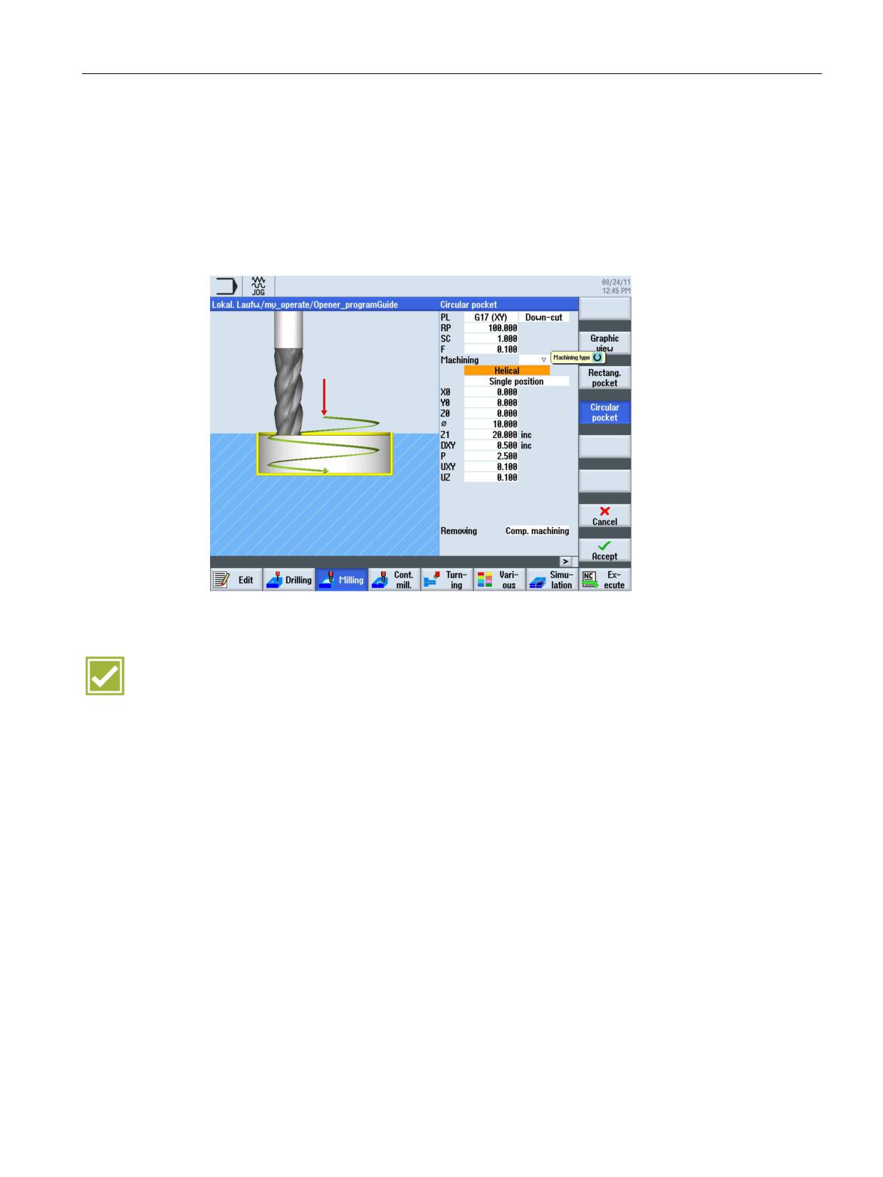
The cycle support is an extension of the highly flexible DIN/ISO programming. The input
screens are based on the ShopMill cycles input screens, so as to ensure optimum
consistency.
The calls for tool, feedrate and spindle speed can of course also be input in the DIN/ISO
editor.
Benefits
Ⴠ Existing DIN/ISO part programs with cycles can continue to be used
Ⴠ Minimum learning requirements due to the consistency of the input support
SINUMERIK Operate - Milling
Control system overview for machine tools' sales people, 2017, A5E41992599B AA
71

CNC programming methods
11.2 ShopMill - machining step programming
11.2
ShopMill - machining step programming
11.2.1
Introduction
SINUMERIK 828D
SINUMERIK 828D
SINUMERIK 828D
BASIC
ADVANCED
Option: P17
Option: P17
Option: P17
SINUMERIK 840D sl
SINUMERIK 840D sl
BASIC
Option: P17
Option: P17
The following information provides you with an overview of the characteristic functions of
ShopMill. This includes:
Ⴠ Sequence editor
Ⴠ Interlinking of sequences
Ⴠ Broken-line graphics
These functions are part of the machining step programming options package in ShopMill.
SINUMERIK Operate - Milling
72
Control system overview for machine tools' sales people, 2017, A5E41992599B AA

CNC programming methods
11.2 ShopMill - machining step programming
11.2.2
Sequence editor
The graphical programming is performed via a graphic interactive sequence editor. Each
program line represents a technological sequence (such as: face milling, centering, drilling,
tapping) or geometric data required for the sequences (position patterns or contours). Graph-
ical programming offers, in comparison to DIN/ISO programming, a compact and compre-
hensible program overview.
Entering individual sequences requires no
knowledge of DIN/ISO. All required technolog-
ical and geometric parameters are entered in
screen forms. Simple, intuitive programming
with sequences can always be expanded very
flexibly by inputting DIN/ISO blocks and con-
trol functions.
Benefits
Ⴠ Intuitive program input, without knowledge of DIN/ISO and the Operating Manual
Ⴠ Compact, clearly arranged machining programs
Ⴠ Reducing the programming time by graphical input masks and copying/pasting machining
steps
SINUMERIK Operate - Milling
Control system overview for machine tools' sales people, 2017, A5E41992599B AA
73
CNC programming methods
11.2 ShopMill - machining step programming
11.2.3
Interlinking of sequences
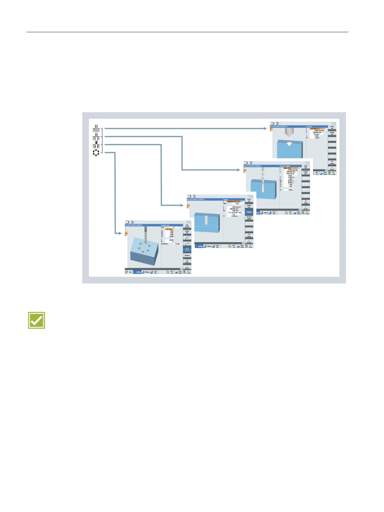
In ShopMill, associated sequences are interlinked with each other. The interlinked
sequences are performed consecutively at the appropriate contours or pattern positions.
In the following example, the sequences centering, deep-hole drilling and tapping are applied
to 6 holes on the pitch circle pattern position.
Benefit
Ⴠ Reduced programming time due to linking of machining steps
SINUMERIK Operate - Milling
74
Control system overview for machine tools' sales people, 2017, A5E41992599B AA
CNC programming methods
11.2 ShopMill - machining step programming
11.2.4
Graphic view
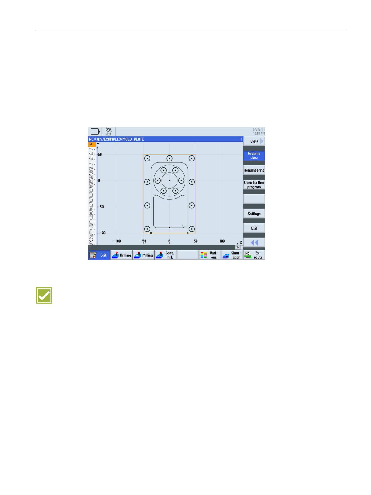
While programming, the previously entered sequences will be continuously displayed to
scale. A simulation is not required for this. The switching between the machining step
program and the broken-line graphics is performed with the "Graphics View" softkey or the
"Ctrl+G" shortcut.
Ⴠ Plan view of workpiece
Ⴠ Front view of drilling operations
Benefit
Ⴠ Increased reliability at program input by quickly checking the contour, without having to
start a simulation run
SINUMERIK Operate - Milling
Control system overview for machine tools' sales people, 2017, A5E41992599B AA
75
CNC programming methods
11.2 ShopMill - machining step programming
SINUMERIK Operate - Milling
76
Control system overview for machine tools' sales people, 2017, A5E41992599B AA
Workpiece visualization
12
12.1
2D simulation
SINUMERIK 828D
SINUMERIK 828D
SINUMERIK 828D
BASIC
ADVANCED
Basic configuration
Basic configuration
Basic configuration
SINUMERIK 840D sl
SINUMERIK 840D sl
BASIC
Basic configuration
Basic configuration
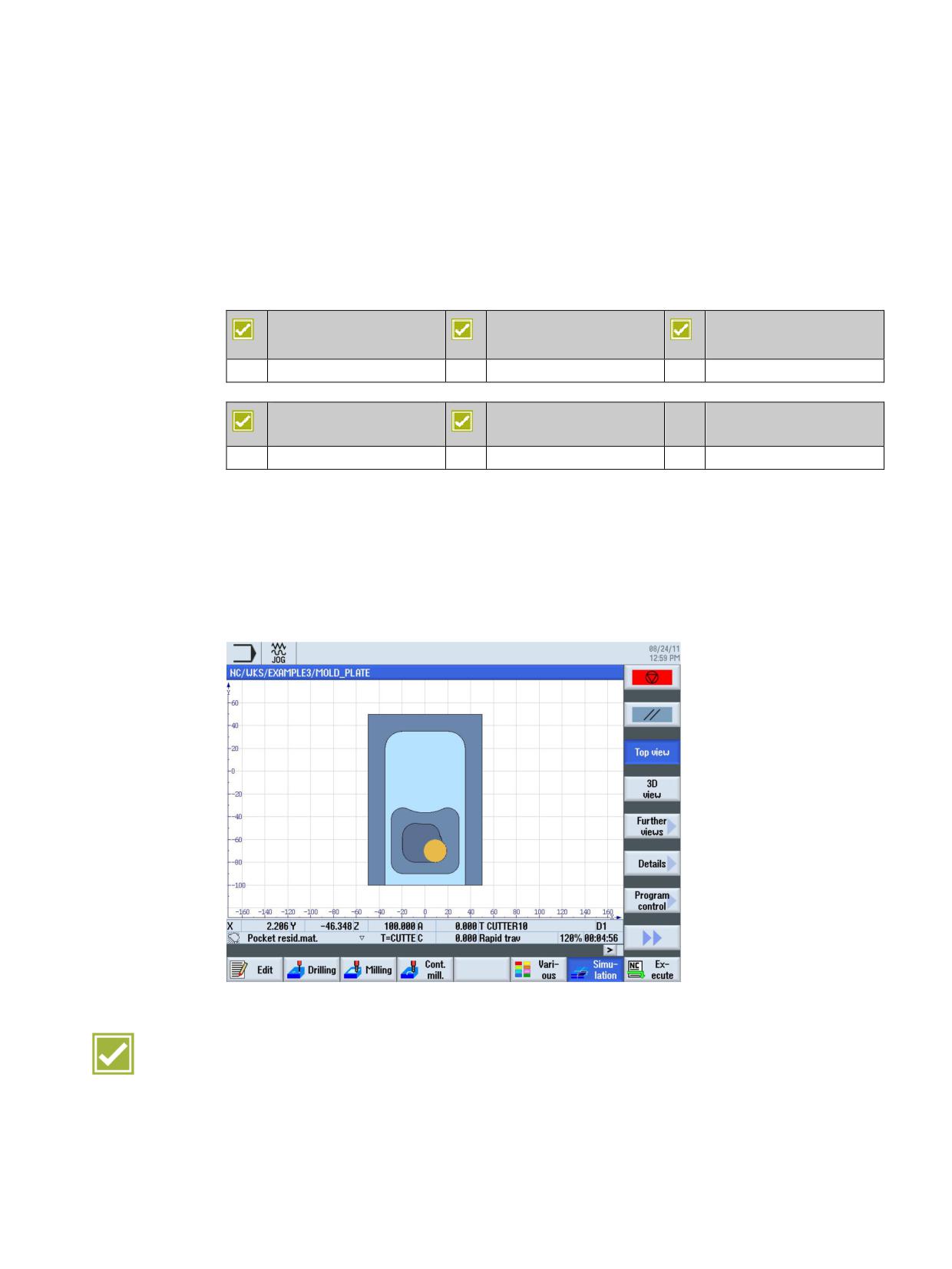
SINUMERIK Operate offers with 2D simulation the facility to make optimum and reliable
preparations for machining workpieces, such as by detecting collisions. Calculating the
machining time also supports optimum calculation of tooling costs.
Ⴠ Use of the real geometry values of the tools mounted in the machine
Ⴠ Simulation in plan view and side view
Ⴠ Simulation can be interrupted at any time, and the speed is controllable
Benefits
Ⴠ Maximum process reliability through simulation using real geometry values
Ⴠ Perfect clarity by showing the workpiece dimensions with a scale
Ⴠ Parallel simulation (backg14round simulation) is possible in conjunction with the NCU 720
and NCU 730, i.e. simulating a part program while another part program is being
simultaneously machined.
SINUMERIK Operate - Milling
Control system overview for machine tools' sales people, 2017, A5E41992599B AA
77
Workpiece visualization
12.2 3D simulation
12.2
3D simulation
SINUMERIK 828D
SINUMERIK 828D
SINUMERIK 828D
BASIC
ADVANCED
Option: P25
Option: P25
Option: P25
SINUMERIK 840D sl
SINUMERIK 840D sl
BASIC
Option: P25
Option: P25
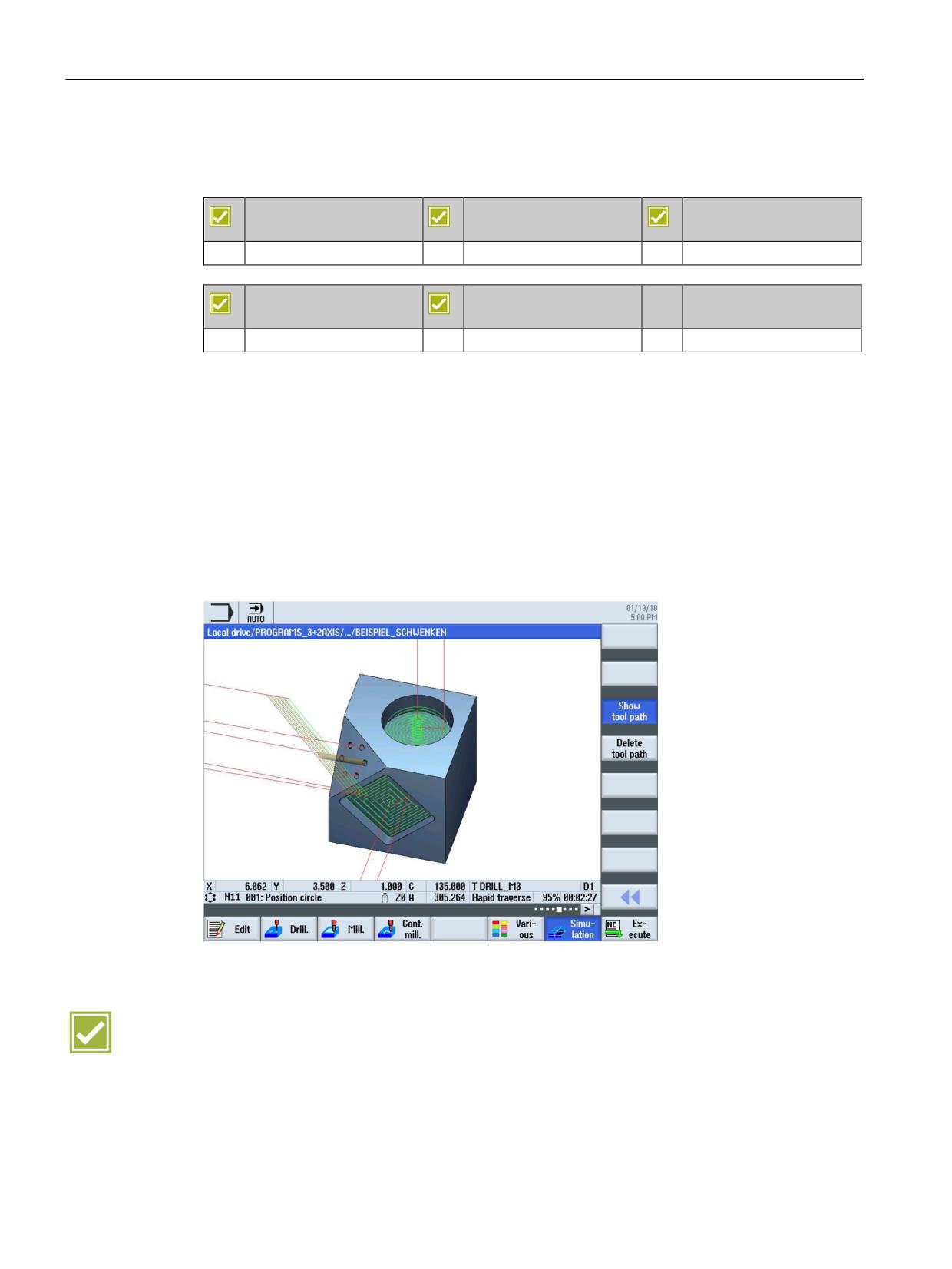
SINUMERIK 3D workpiece simulation offers you optimum assistance and reliability in
programming and in quotation costing.
Ⴠ Reliability:
3 viewing planes and solid model of the finished part, with zoom to details and free
rotation of the viewing angle
Ⴠ Support:
- Simulation speed controllable by override
- Single block operation and start/stop available at any time
Ⴠ Checking:
Automatic calculation of machining time
Benefits
Ⴠ Particularly realistic simulation through representation of the tool
Ⴠ Optimum help and reliability in programming and in quotation costing
Ⴠ Parallel simulation (backg14round simulation) is possible in conjunction with the NCU 720
and NCU 730, i.e. simulating a part program while another part program is being
simultaneously machined.
SINUMERIK Operate - Milling
78
Control system overview for machine tools' sales people, 2017, A5E41992599B AA
Workpiece visualization
12.3 Mold making fast view
12.3
Mold making fast view
SINUMERIK 828D
SINUMERIK 828D
SINUMERIK 828D
BASIC
ADVANCED
Basic configuration
Basic configuration
Basic configuration
SINUMERIK 840D sl
SINUMERIK 840D sl
BASIC
Basic configuration
Basic configuration
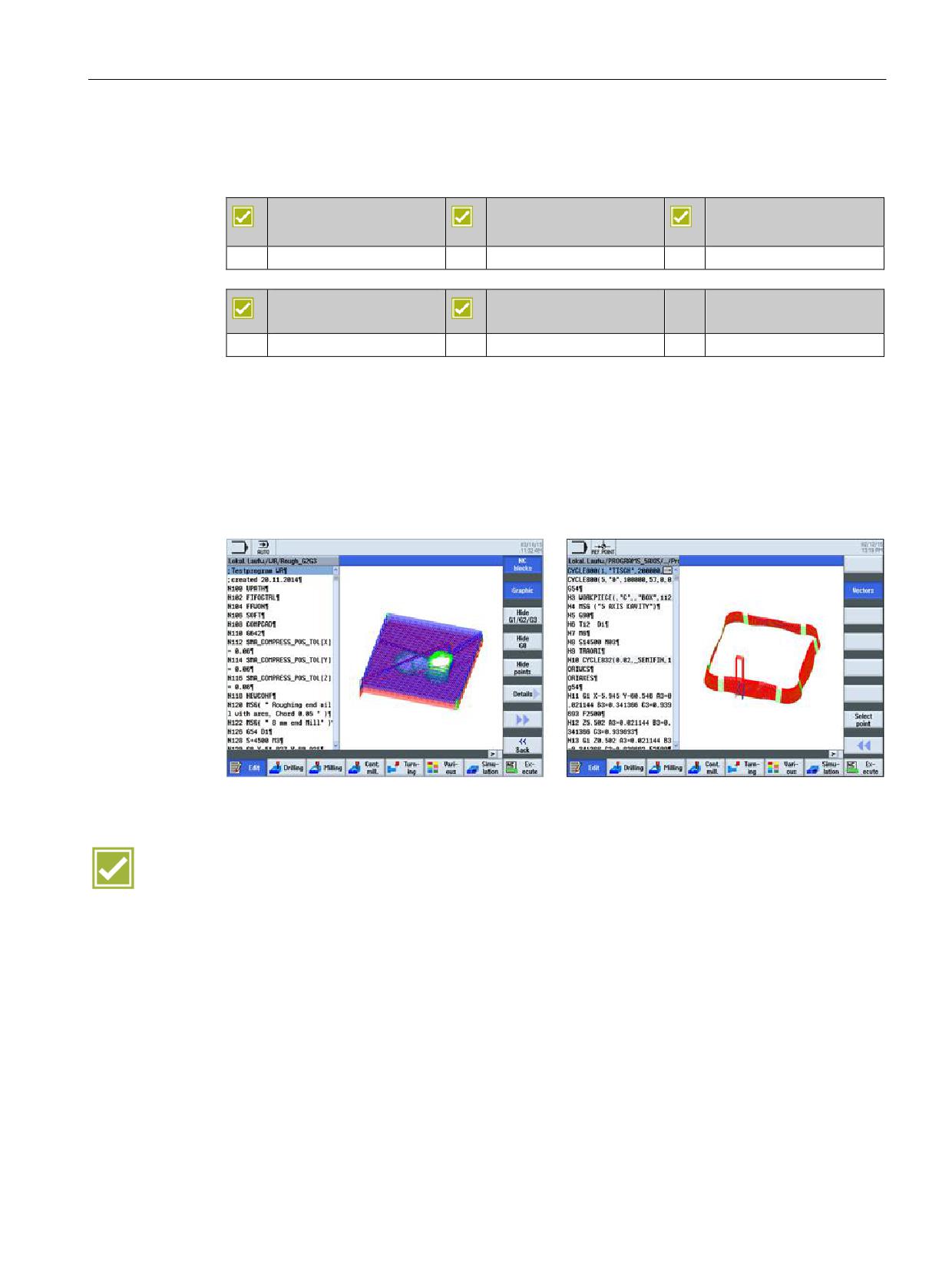
The mold making fast view is available, in particular for large part programs.
Ⴠ Fast view of G0, G1, G2, G3 blocks, VECTORS using the 3D mold building model
Ⴠ Fast identification of part programs where simulation would take a long time
Ⴠ Displaying/hiding G0, G1, G2, G3 lines and points
Ⴠ In addition to the classic view, for mold making programs, you can also display the rotary
axis vectors and grid mesh (surface, mesh), for example.
Benefit
Ⴠ More safety when handling mold making programs
SINUMERIK Operate - Milling
Control system overview for machine tools' sales people, 2017, A5E41992599B AA
79
CNC technology cycles
13
13.1
CNC technology cycles for programGUIDE and ShopMill
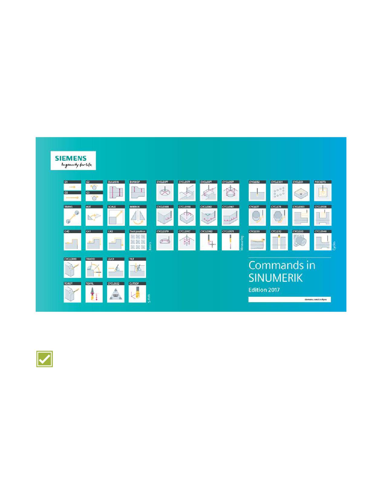
Irrespective of whether you use programGUIDE or ShopMill - in either case the full range of
technological cycles, position patterns and geometries is available to you.
Benefits
Ⴠ Significant simplification of programming, even for complex jobs, using CNC technology
cycles
Ⴠ Consistency of cycles for programGUIDE and ShopMill
SINUMERIK Operate - Milling
Control system overview for machine tools' sales people, 2017, A5E41992599B AA
81
CNC technology cycles
13.2 Highlights of machining cycles
13.2
Highlights of machining cycles
13.2.1
Overview
For frequently repeated machining tasks, machining cycles are available for the drilling,
milling and turning technologies.
Ⴠ Drilling technology:
Drilling/centering, drilling/counterboring, deep-hole drilling, tapping with and without
compensating chuck, boring 1 ... 5, row of holes, circle of holes, grid of holes, machining
on inclined surfaces
Ⴠ Milling technology:
Thread milling, elongated holes in a circle, grooves in a circle, circumferential groove,
rectangular/circular pocket, face milling, path milling, rectangular/circular spigot,
machining on inclined surfaces, high-speed settings for optimized HSC machining,
engraving cycle
Ⴠ Turning technology:
Groove, undercut, cutting with relief cut, thread undercut, thread cutting, chaining of
threads, thread recutting
A selection of machining cycles is explained in more detail below.
SINUMERIK Operate - Milling
82
Control system overview for machine tools' sales people, 2017, A5E41992599B AA
CNC technology cycles
13.2 Highlights of machining cycles
13.2.2
Engraving cycle
SINUMERIK 828D
SINUMERIK 828D
SINUMERIK 828D
BASIC
ADVANCED
Basic configuration
Basic configuration
Basic configuration
SINUMERIK 840D sl
SINUMERIK 840D sl
BASIC
Basic configuration
Basic configuration
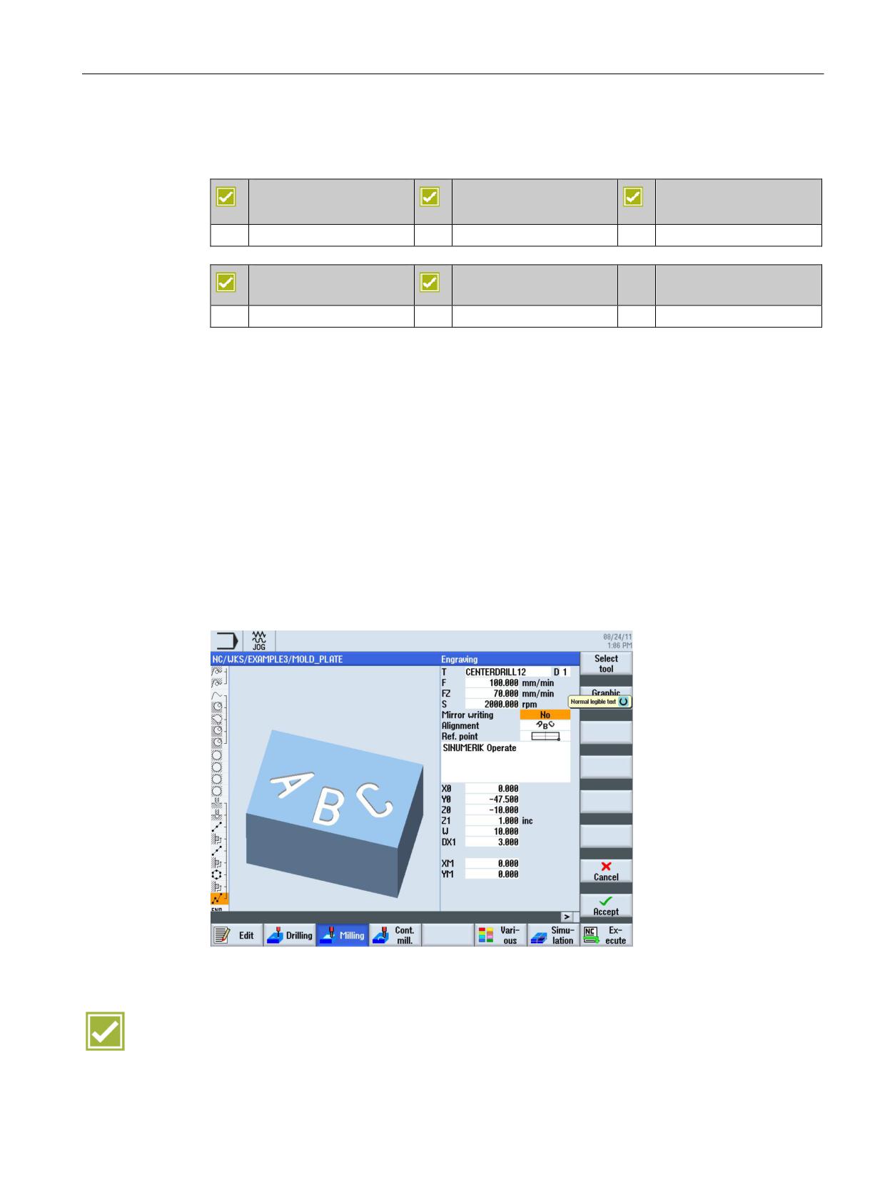
The engraving cycle is used to engrave a text on a workpiece along a line or arc. You can
enter the text as fixed text or assign it via a variable as variable text.
Examples of variable texts:
Ⴠ Date and time
The values for the date and time are read from the CNC.
Ⴠ Quantity
The "Quantity" variable is available as a pre-defined user variable
Ⴠ Numbers
When outputting numbers (e.g. measurement results), you can select the output format
(digits before and after the point) of the number to be engraved.
Ⴠ Text
Instead of entering a fixed text in the engraving text field, you can specify the text to be
engraved via a text variable (e.g., _VAR_TEXT="ABC123").
Benefits
Ⴠ Reduction of set-up times by complete machining on one machine
Ⴠ Simple program input of engraving
SINUMERIK Operate - Milling
Control system overview for machine tools' sales people, 2017, A5E41992599B AA
83
CNC technology cycles
13.2 Highlights of machining cycles
13.2.3
Trochoidal milling
SINUMERIK 828D
SINUMERIK 828D
SINUMERIK 828D
BASIC
ADVANCED
Basic configuration
Basic configuration
Basic configuration
SINUMERIK 840D sl
SINUMERIK 840D sl
BASIC
Basic configuration
Basic configuration
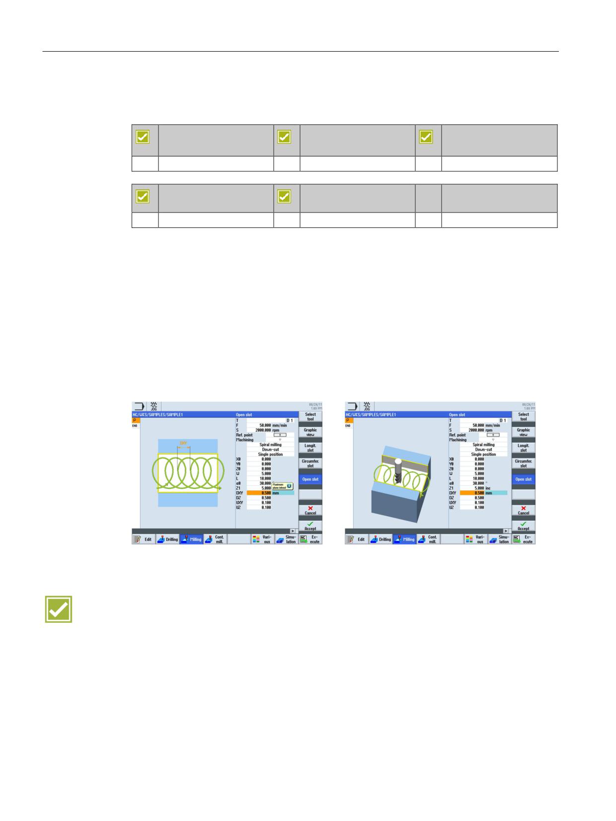
Vortex milling (trochoidal milling) of open slots is available as a milling strategy directly on
the controller, i.e. NC programs for path motions do not have to be generated by CAM
systems as previously.
Ⴠ It is the preferred strategy for HSC roughing, the tool is never fully inserted and tool paths
are smooth and round
Ⴠ Simple parameterizing per dialog: Roughing, pre-finishing, finish milling, finishing floor
and edge
Ⴠ You can select as milling direction synchronous operation, reverse rotation, and for
maximum cutting volume during roughing the combination reverse rotation and
synchronous operation
Benefits
Ⴠ Innovative CAM function now available directly on the controller
Ⴠ Reduction in the machining time for slot milling by up to 50%
SINUMERIK Operate - Milling
84
Control system overview for machine tools' sales people, 2017, A5E41992599B AA
CNC technology cycles
13.2 Highlights of machining cycles
13.2.4
Plunge milling
SINUMERIK 828D
SINUMERIK 828D
SINUMERIK 828D
BASIC
ADVANCED
Basic configuration
Basic configuration
Basic configuration
SINUMERIK 840D sl
SINUMERIK 840D sl
BASIC
Basic configuration
Basic configuration
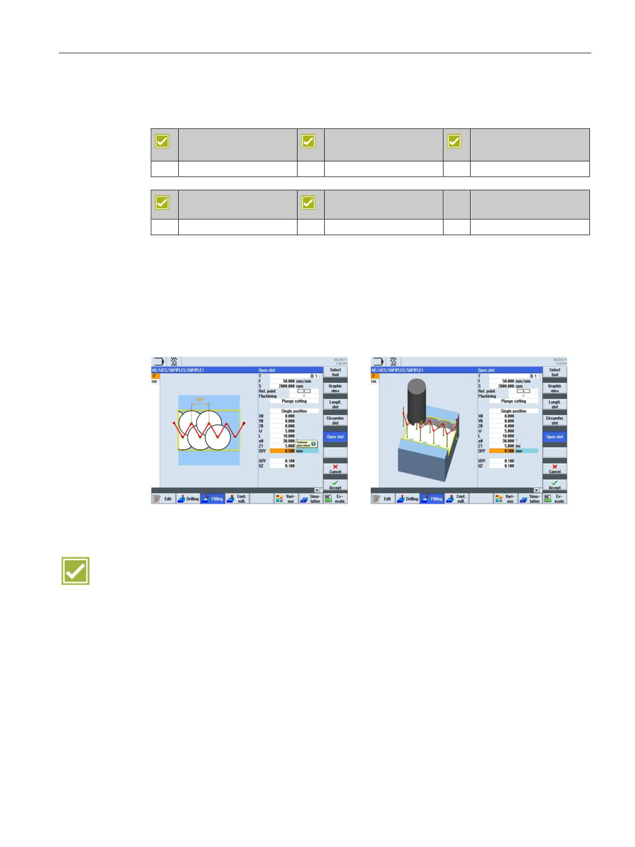
For machining deep pockets and slots in thin-walled workpieces, the plunge milling cycle is
available for open slots.
Ⴠ As types of machining you can select roughing, pre-finishing and finishing of the edge
and/or floor
Ⴠ Essentially, forces apply only along the main spindle axis, therefore, hardly any distortion
of the tool occurs.
Benefits
Ⴠ Less vibrations and deeper cutting depth thanks to the new machining strategy plunge
milling
Ⴠ Reduced cutting pressure and distortion enable higher productivity when machining thin-
walled workpieces
SINUMERIK Operate - Milling
Control system overview for machine tools' sales people, 2017, A5E41992599B AA
85
CNC technology cycles
13.2 Highlights of machining cycles
13.2.5
Deep-hole drilling
SINUMERIK 828D
SINUMERIK 828D
SINUMERIK 828D
BASIC
ADVANCED
Basic configuration
Basic configuration
Basic configuration
SINUMERIK 840D sl
SINUMERIK 840D sl
BASIC
Basic configuration
Basic configuration
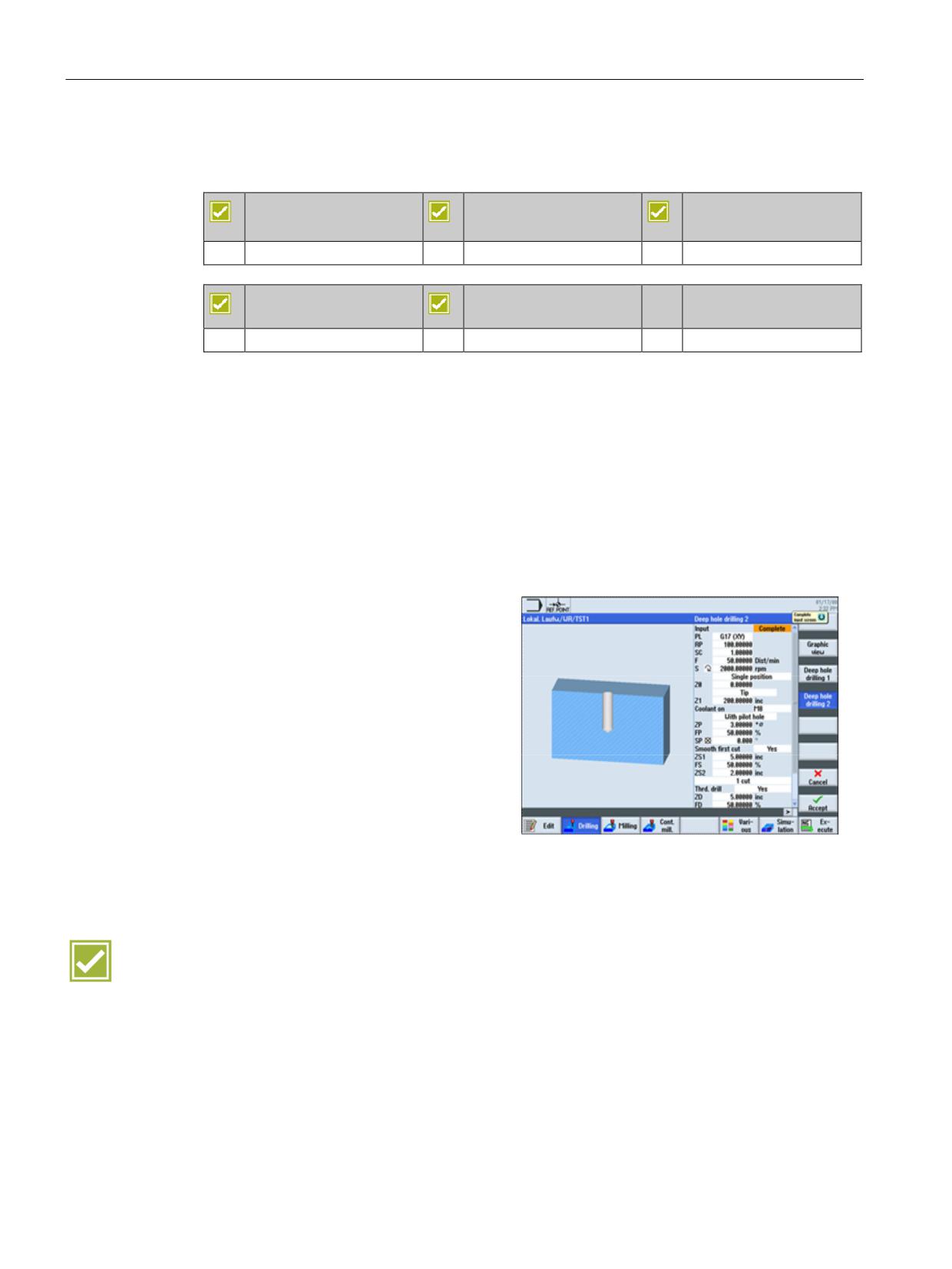
Easy-to-use cycles for deep-hole drilling are available in SINUMERIK Operate.
The tool drills at the programmed spindle speed and feedrate to the entered final drilling
depth.
Deep hole drilling is performed with a depth infeed of a maximum definable depth executed
several times, increasing gradually until the final drilling depth is reached.
For example, the drilling machine can be retracted after each infeed depth either to the
piloting depth + safety clearance for chip removal or by the length of the programmed
retraction path for chip breakage.
You can also choose between the following drilling strategies:
x With or without predrilling
x With or without pilot hole
x Soft first cut yes/no
x Chip breaking/removal
x Chip breaking and swarf removal
x
1 cut - drill in one step to the end
depth
x Swarf removal to the piloting depth /
safety clearance
x Retraction to the piloting depth /
retraction plane
x Position pattern
Benefit
Ⴠ Generate drill holes with more than one feed to any positions
SINUMERIK Operate - Milling
86
Control system overview for machine tools' sales people, 2017, A5E41992599B AA
CNC technology cycles
13.3 Residual material detection for contour cycles
13.3
Residual material detection for contour cycles
SINUMERIK 828D
SINUMERIK 828D
SINUMERIK 828D
BASIC
ADVANCED
Option: P13
Option: P13
Option: P13
SINUMERIK 840D sl
SINUMERIK 840D sl
BASIC
Option: P13
Option: P13
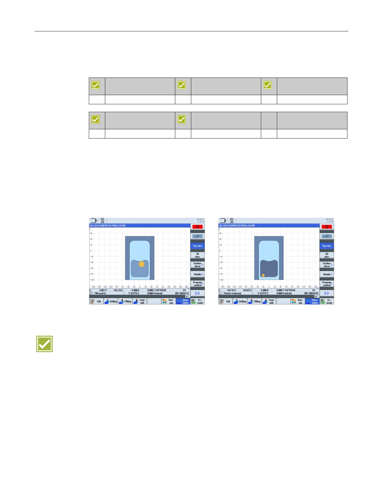
Contour ranges which do not permit milling with large diameters are automatically identified
in the cycle for contour pockets and contour spigots. These areas can be selectively
machined with a suitable smaller tool, rather than having to use this tool for the entire
contour pocket or spigot.
If you mill several pockets and wish to avoid unnecessary tool changeovers, remove stock
from all the pockets first and then remove the residual material. In this case, you must enter
the tool used for removing the residual material from the pocket in the "TR reference tool"
parameter.
Benefits
Ⴠ Shorter machining times through the use of a large tool for the substantial part of the
stock removal and a smaller tool for the remaining residual material
Ⴠ Avoidance of non-cutting movements while achieving extremely simple programming
SINUMERIK Operate - Milling
Control system overview for machine tools' sales people, 2017, A5E41992599B AA
87