SINUMERIK 840D sl. Training. Operate - Turning (2016-2020) - page 15
CNC technology cycles
13.4 In-process measuring for workpiece and tool
13.4
In-process measuring for workpiece and tool
SINUMERIK 828D
SINUMERIK 828D
SINUMERIK 828D
BASIC
ADVANCED
Option: P28
Option: P28
Option: P28
SINUMERIK 840D sl
SINUMERIK 840D sl
BASIC
Option: P28
Option: P28
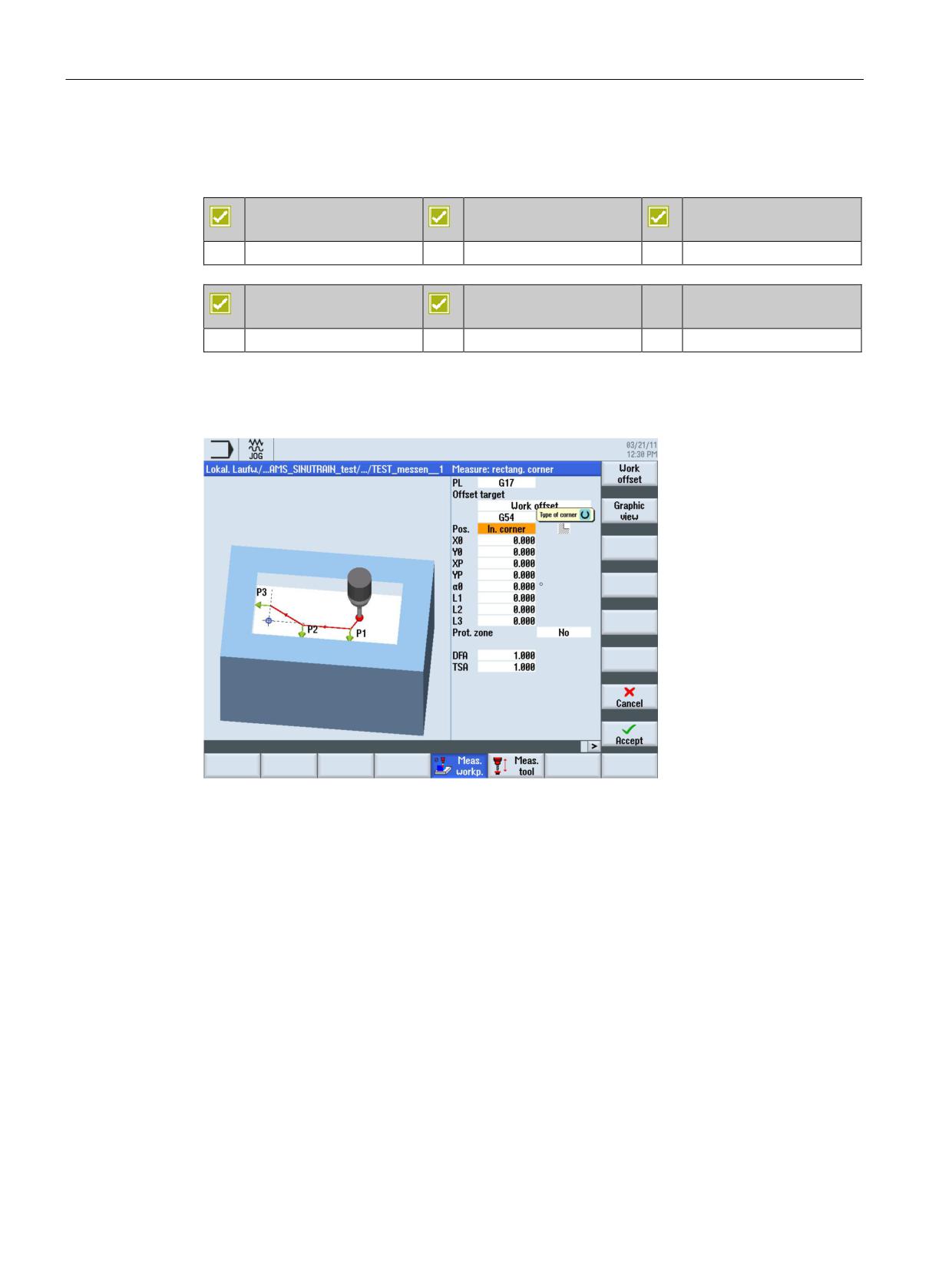
For measuring tasks in the automatic mode, powerful measuring cycles are available both
under ShopMill as well as under programGUIDE. Input screens with dynamic help displays
are used for convenient entry of the measuring parameters.
You can perform the following measuring tasks:
Ⴠ Workpiece measurement: Correction of work offsets, correction of tool geometry or only
measuring
Ⴠ Tool measurement: Correction of tool geometries
Ⴠ Display of measurement results
Ⴠ Logging of measurement results
SINUMERIK Operate - Milling
88
Control system overview for machine tools' sales people, 2017, A5E41992599B AA
CNC technology cycles
13.4 In-process measuring for workpiece and tool
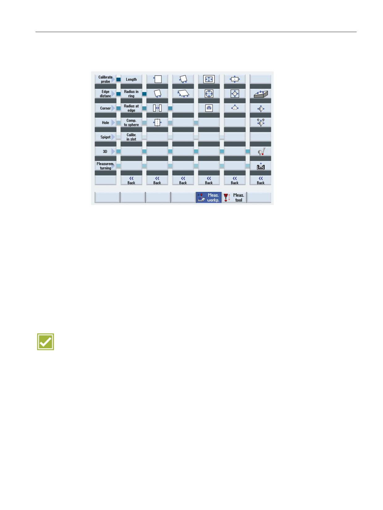
The following workpiece measuring versions are available:
Figure 13-1 In-process measurement
Ⴠ Calibrating - length, radius in ring, radius at edge, calibration on a sphere, calibration in a
slot
Ⴠ Measuring edge - point/ surface, align edge, distance groove/web,
Ⴠ Measuring corner - right-angled corner with 3 points or any corner with 4 points,
internal/external
Ⴠ Measuring holes - over 4 or 3 points on a segment of a circle - rectangular pocket
Ⴠ Measuring spigots - over 4 or 3 points on a segment of a circle - rectangular pocket
Ⴠ 3D measuring - align plane - sphere
Benefits
Ⴠ Reliable quality of the manufactured parts by automatic measurement in the machine
Ⴠ Fast programming for complex measuring tasks thanks to input screens with graphic
support
Ⴠ Measuring cycles are now also available for ShopMill sequence programs
SINUMERIK Operate - Milling
Control system overview for machine tools' sales people, 2017, A5E41992599B AA
89
CNC technology cycles
13.5 Measure multiple axis kinematics
13.5
Measure multiple axis kinematics
SINUMERIK 828D
SINUMERIK 828D
SINUMERIK 828D
BASIC
ADVANCED
Option: P18
Option: P18
Option: P18
SINUMERIK 840D sl
SINUMERIK 840D sl
BASIC
Option: P18
Option: P18
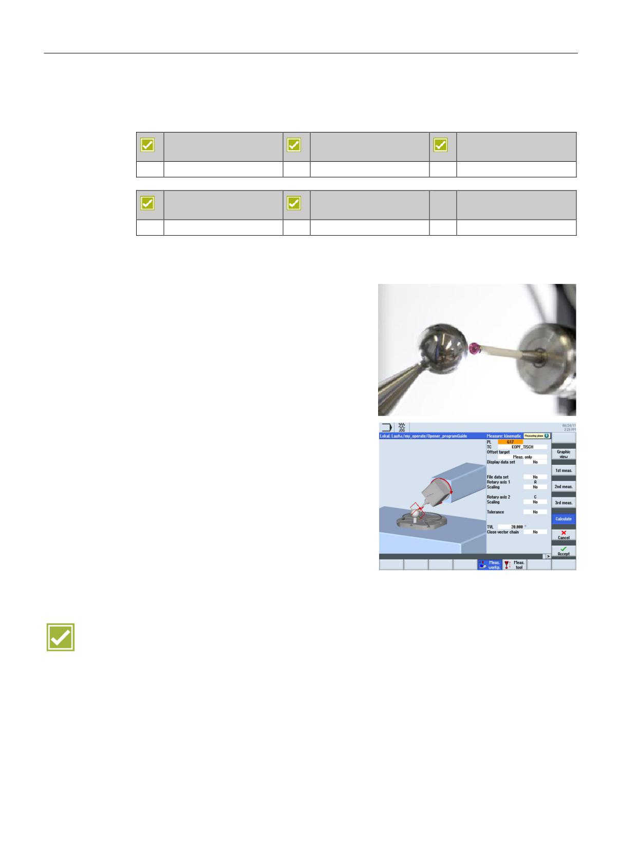
The kinematic measuring cycle CYCLE996 of SINUMERIK 840D sl allows axis kinematics of
machine tools - equipped with several rotary axes - to be measured.
x Application during start-up and
commissioning and for the control of the
machine: The cycle makes control easier
and improves the quality of the process as
compensations of the rotary axis vectors -
due, for example, to temperature variations,
mechanical damage or other influential
factors - can be checked automatically.
x Input of compensation values after the
measuring process for the digital alignment
of the rotary axis or acquisition of the
measured values for documentation
purposes. Tolerance values are freely
selectable.
Benefits
Ⴠ Simplest measuring cycle to measure machines with rotary axes in the shortest time
Ⴠ Simple measurement or direct correction with freely selectable tolerance values
SINUMERIK Operate - Milling
90
Control system overview for machine tools' sales people, 2017, A5E41992599B AA
Complete machining
14
14.1
Cylinder surface transformation (TRACYL)
SINUMERIK 828D
SINUMERIK 828D
SINUMERIK 828D
BASIC
ADVANCED
Option: M27
Option: M27
Option: M27
SINUMERIK 840D sl
SINUMERIK 840D sl
BASIC
Option: M27
Option: M27
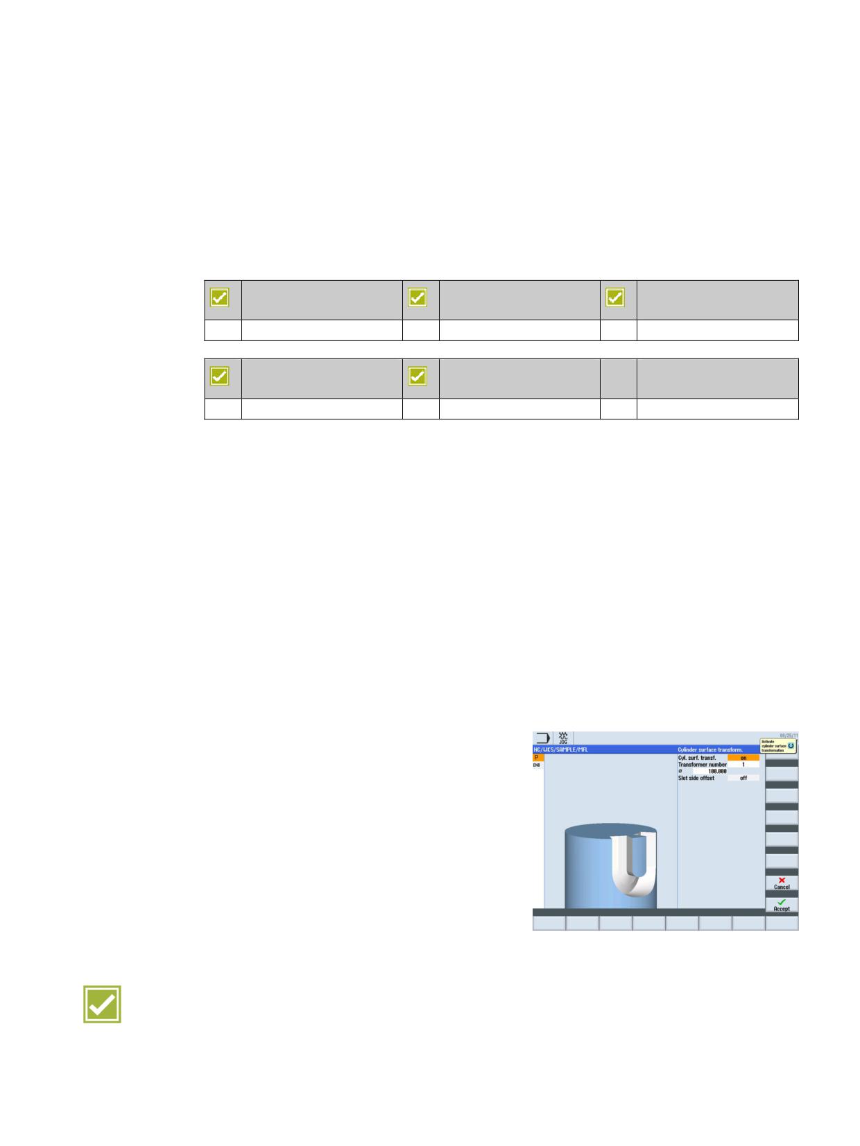
Peripheral surface machining can be executed on machines with an additional part
apparatus. It is typically handled with an A axis.
Peripheral surface machining offers a series of additional functions in comparison to simple
positioning along the A axis.
Programming in the run-off
The axis behaves like a Y axis while programming in the run-off. All plane machining can
also be executed in the run-off.
Ⴠ Drilling operations at any position patterns
Ⴠ Milling (pockets, contour pockets)
The Y values are converted while machining along the A axis rotation. The Y axis of the
machine does not move.
Milling grooves with parallel walls
Peripheral surface machining offers the
possibility of milling grooves on parallel
walls with and without groove side
offset. This is also possible when the
diameter of the milling cutter is smaller
than the groove width. In this case, the
cutter radius compensation may be
used. The required Y axis compensat-
ing movements are automatically cal-
culated by the controller.
Benefits
Ⴠ Additional business through expansion of workpiece spectrum
Ⴠ Reduction of set-up times by complete machining on one machine
SINUMERIK Operate - Milling
Control system overview for machine tools' sales people, 2017, A5E41992599B AA
91
Complete machining
14.2 Swivel plane (CYCLE800)
14.2
Swivel plane (CYCLE800)
SINUMERIK 828D
SINUMERIK 828D
SINUMERIK 828D
BASIC
ADVANCED
Basic configuration
Basic configuration
Basic configuration
SINUMERIK 840D sl
SINUMERIK 840D sl
BASIC
Basic configuration
Basic configuration
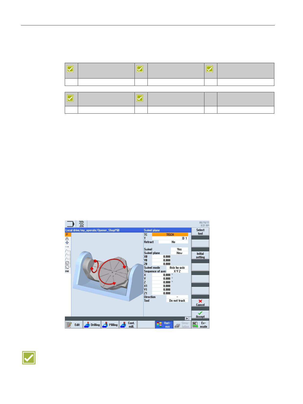
Multi-face machining saves setup times and increases the precision of finished adjoining
sides because the part must not be reclamped. The swivel cycle is used for easy input of
parameters for automatic machining and measuring on the various planes.
Ⴠ A prerequisite is that the machine is equipped with additional rotary axes (swivel head
and/or swivel table).
Ⴠ The swivel cycle is available in the ShopMill machining step - as well as in
programGUIDE DIN/ISO programming.
Ⴠ The planes can be swiveled not only by direct swiveling with rotation of coordinates and
swiveling about the axes, but also by specifying a projection or spatial angle for swiveling.
Ⴠ Flexible combination of shift - swivel - shift.
Ⴠ Turning or moving are not machine-specific, as they are based on the workpiece
coordinate system X, Y and Z.
Ⴠ Fixed relief positions available
Benefit
Ⴠ Programming with standard cycles and easy transformation on the inclined plane through
the swivel cycle
SINUMERIK Operate - Milling
92
Control system overview for machine tools' sales people, 2017, A5E41992599B AA
Complete machining
14.3 5-axis machining package (TRAORI)
14.3
5-axis machining package (TRAORI)
SINUMERIK 828D
SINUMERIK 828D
SINUMERIK 828D
BASIC
ADVANCED
not available
not available
not available
SINUMERIK 840D sl
SINUMERIK 840D sl
BASIC
Option: S33 (Package)
Option: S33 (Package)
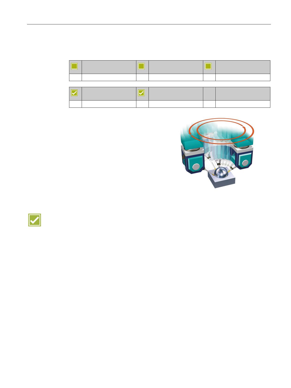
In contrast to static transformations (swiveling)
in which the tool is perpendicular to the ma-
chining plane, the 5-axis machining package
TRAORI allows the dynamic coupled motion
of a tool along the workpiece surface. It is
used for 5-axis mold making applications and
in the aviation industry, for example.
x Any tool orientation
x Remote Tool Center Point function (RTCP)
x Part programs not dependant on
kinematics (vector programming)
Benefits
Ⴠ Programming the tooltip in workpiece coordinates
Ⴠ Programmed speed with reference to the tooltip
Ⴠ Programming the tool orientation independent of the machine kinematics
SINUMERIK Operate - Milling
Control system overview for machine tools' sales people, 2017, A5E41992599B AA
93

Complete machining
14.4 Milling-turning
14.4
Milling-turning
14.4.1
Introduction
SINUMERIK 828D
SINUMERIK 828D
SINUMERIK 828D
BASIC
ADVANCED
not available
not available
not available
SINUMERIK 840D sl
SINUMERIK 840D sl
BASIC
Basic configuration
Basic configuration
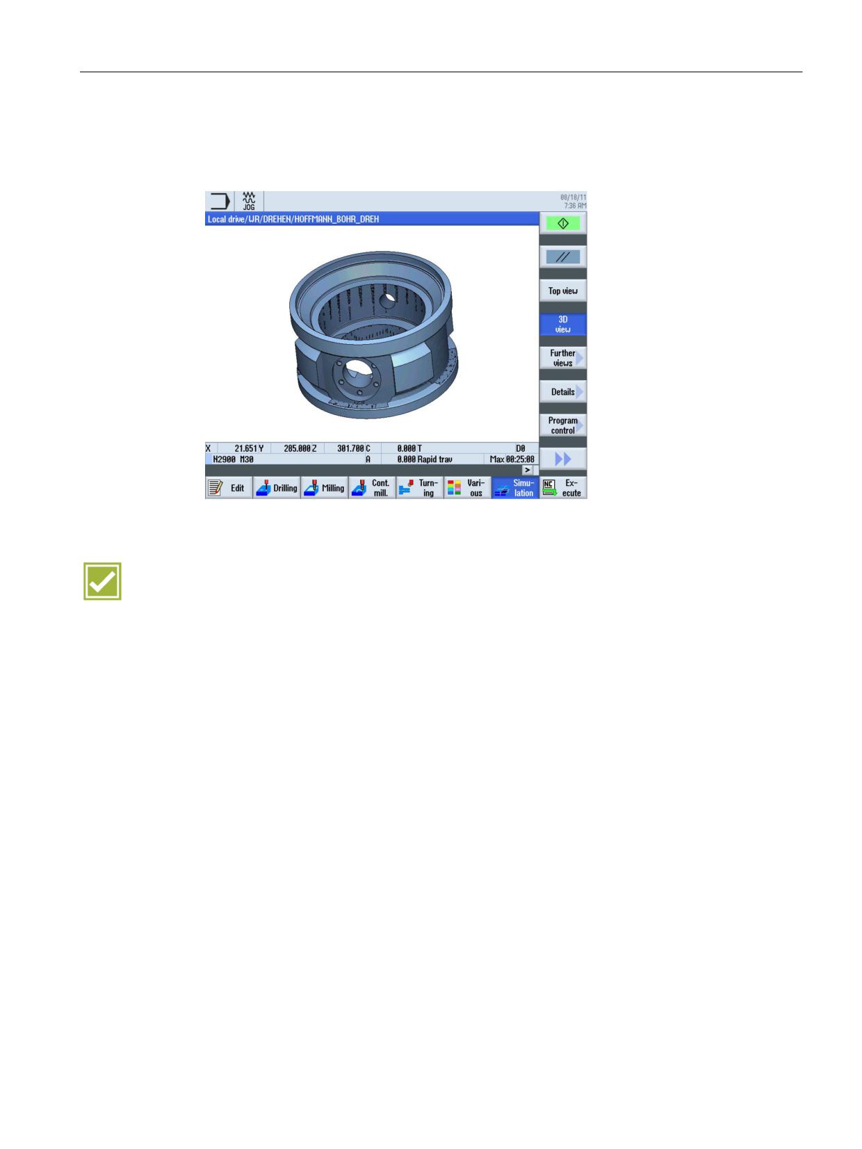
The milling technology in ShopMill and programGUIDE provides comprehensive technology
cycles for turning and contour turning.
Among others, the following functions are available for milling-turning:
Ⴠ TSM mode
Ⴠ Tool measurement
Ⴠ Face milling / stock removal
Ⴠ Turning cycles for stock removal, grooving, undercutting, threading and tapping
Ⴠ Contour turning cycles for stock removal / residual stock removal, plunge cutting /
residual plunge cutting, plunge turning / residual plunge turning
Ⴠ Swivel tool
You can check the programming result, even for milling-turning, with the Simulation function.
Benefits
Ⴠ Consistent look-and-feel for turning and milling permits a high degree of consistency in
the operation and programming for milling-turning
Ⴠ Consistent technology cycles for milling, turning and measuring tasks
Ⴠ Powerful tool management for milling-turning, including multitools
Ⴠ Simulation permits a high degree of process reliability
SINUMERIK Operate - Milling
94
Control system overview for machine tools' sales people, 2017, A5E41992599B AA
Complete machining
14.4 Milling-turning
14.4.2
Tool management
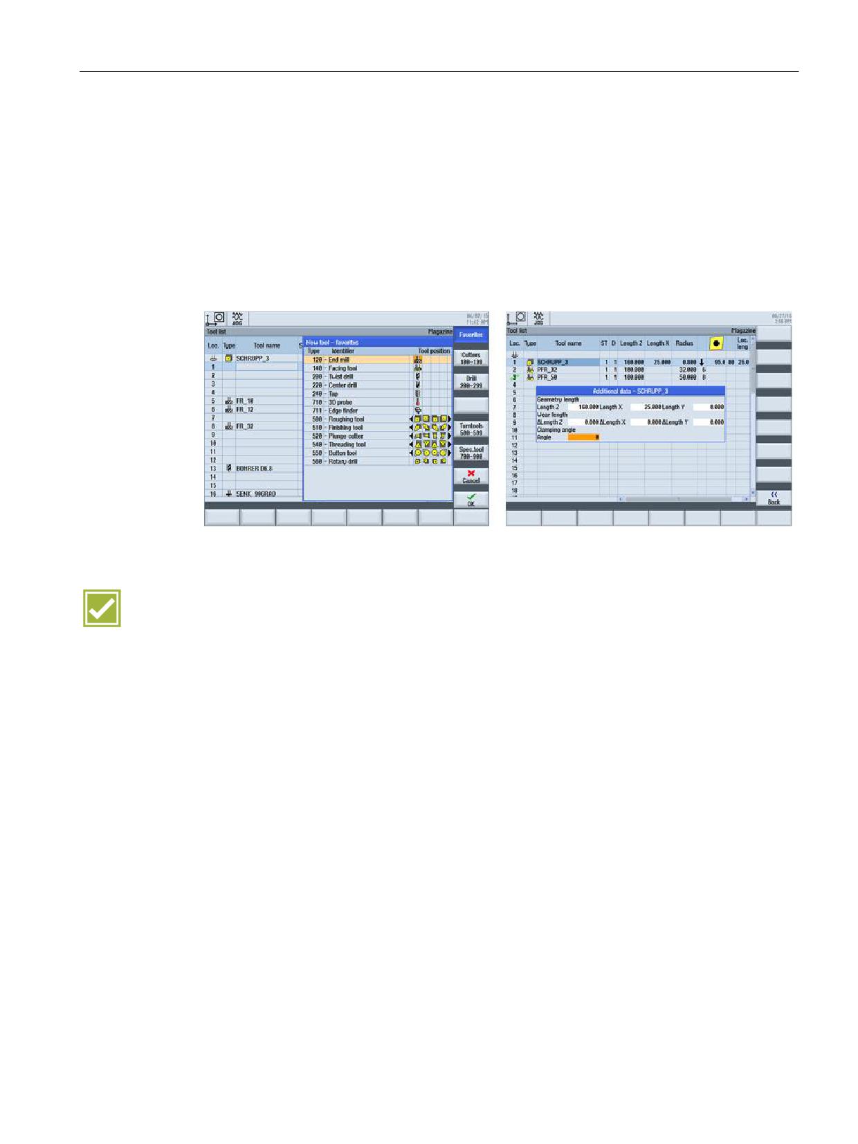
For multitasking machines - for milling-turning or turning-milling - you are provided with an
extended tool management for turning and milling tools.
The turning tools are displayed automatically in the milling-turning technology. In the
"Extended data" dialog, you can enter the tool-specific basic rotation for the turning tools.
In addition to turning and milling tools, you can also deploy complex tools, such as multitools.
There are additional parameters for multitools, e.g. distance definition using the location
number or angle - and different tool types for each location. All tools are shown as icons
Benefits
Ⴠ One tool management for turning and milling tools - including support for multitools
Ⴠ All tools are displayed as symbols
Ⴠ Tool name in plain text
SINUMERIK Operate - Milling
Control system overview for machine tools' sales people, 2017, A5E41992599B AA
95
Complete machining
14.4 Milling-turning
14.4.3
Programming
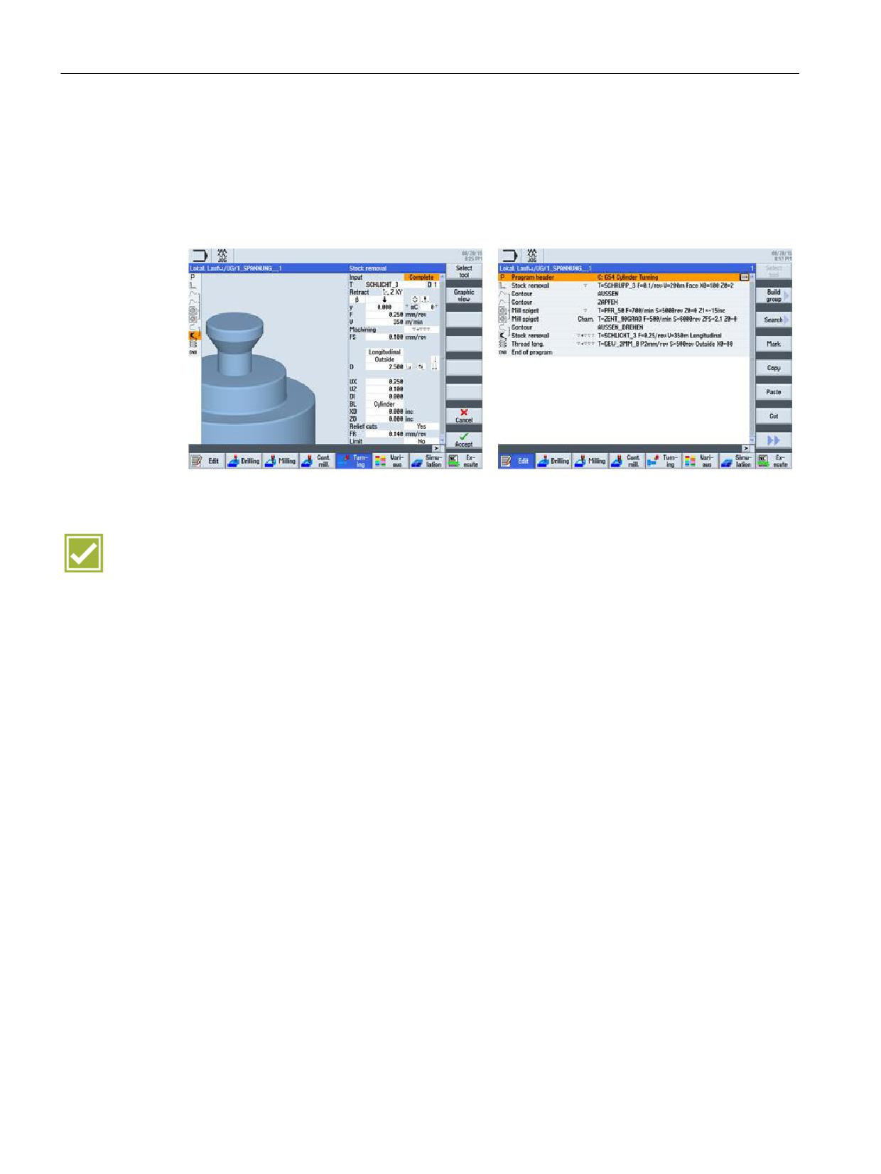
For milling-turning machining, programGUIDE and ShopMill provide not only standard
cycles, but also turning cycles and contour cycles. You are supported with the appropriate
cycles for turning machining as well as turning contour machining and aligning the turning
tool.
Benefit
Ⴠ Turning cycles for programGUIDE and ShopMill as for SINUMERIK Operate turning
technology
SINUMERIK Operate - Milling
96
Control system overview for machine tools' sales people, 2017, A5E41992599B AA
Complete machining
14.4 Milling-turning
14.4.4
Simulation
Also for milling-turning, the usual views are available to simulate the workpiece.
Benefits
Ⴠ Maximum process reliability through simulation using real geometry values
SINUMERIK Operate - Milling
Control system overview for machine tools' sales people, 2017, A5E41992599B AA
97
Complete machining
14.4 Milling-turning
SINUMERIK Operate - Milling
98
Control system overview for machine tools' sales people, 2017, A5E41992599B AA

SINUMERIK Integrate Run MyRobot
15
15.1
SINUMERIK Integrate Run MyRobot / EasyConnect
SINUMERIK 828D
SINUMERIK 828D
SINUMERIK 828D
BASIC
ADVANCED
Basic configuration
Basic configuration
Basic configuration
SINUMERIK 840D sl
SINUMERIK 840D sl
BASIC
Basic configuration
Basic configuration
The prepared Run MyRobot / EasyConnect configuring interface permits the connection of
handling robots to machine tools.
Ⴠ Prepared NC/PLC interface in accordance with VDMA/VDW 34180
Ⴠ Prepared CNC diagnostic screen
Note:
The robot is normally connected to the CNC by the machine manufacturer or a system
integrator.
Benefit
Ⴠ The prepared Run MyRobot / EasyConnect configuration interface provides a universal
and manufacturer-independent interface for the low-effort automation of machine tools.
SINUMERIK Operate - Milling
Control system overview for machine tools' sales people, 2017, A5E41992599B AA
99

SINUMERIK Integrate Run MyRobot
15.2 SINUMERIK Integrate Run MyRobot / Handling
15.2
SINUMERIK Integrate Run MyRobot / Handling
SINUMERIK 828D
SINUMERIK 828D
SINUMERIK 828D
BASIC
ADVANCED
not available
not available
not available
SINUMERIK 840D sl
SINUMERIK 840D sl
BASIC
Option: P74
Option: P74
The Run MyRobot / Handling option enables a robot to be operated, programmed and
diagnosed for handling tasks with SINUMERIK Operate.
Ⴠ Operation, teaching and programming of the robot in the familiar CNC programming
environment.
Ⴠ Minimum training effort, because fully integrated in SINUMERIK Operate.
Ⴠ Efficient loading and unloading of a machine by direct programming in a control system.
Note
The robot is connected to the CNC by the machine tool manufacturer or a recommended*
system integrator.
* For details, please contact your local Siemens office.
Benefit
Ⴠ Run MyRobot / Handling offers the integration of handling robots in machine tools with
the best-possible user-friendliness thanks to the familiar CNC look-and-feel.
SINUMERIK Operate - Milling
100
Control system overview for machine tools' sales people, 2017, A5E41992599B AA
Tools and information
16
16.1
DXF reader
SINUMERIK 828D
SINUMERIK 828D
SINUMERIK 828D
BASIC
ADVANCED
Option: P56
Option: P56
Option: P56
SINUMERIK 840D sl
SINUMERIK 840D sl
BASIC
Option: P56
Option: P56
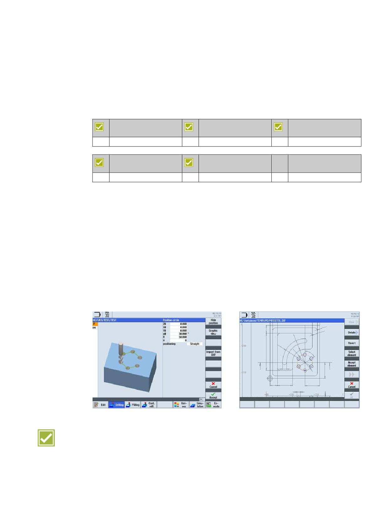
The integrated DXF Reader allows you to accept and extract contours and positions from
DXF files.
Ⴠ DXF Reader in the Program Manager
With the Program Manager, you can open DXF files in the DXF Reader. You can either
clean DXF data automatically or select the desired layer yourself.
Ⴠ Import DXF data in the contour calculator
You can either clean the imported DXF data automatically or select the desired layer
yourself.
Cleaned DXF data can be buffered as new DXF file.
Ⴠ Import DXF data in position patterns
You can import the positions from a DXF file for position patterns for the associated
technologies.
Benefits
Ⴠ Time saving for generating the production data
Ⴠ Avoidance of mistakes and inaccuracies
Ⴠ Higher workpiece quality
SINUMERIK Operate - Milling
Control system overview for machine tools' sales people, 2017, A5E41992599B AA
101

Tools and information
16.2 SinuTrain for SINUMERIK Operate
16.2
SinuTrain for SINUMERIK Operate
SINUMERIK 828D
SINUMERIK 828D
SINUMERIK 828D
BASIC
ADVANCED
Option: C43
Option: C43
Option: C43
SINUMERIK 840D sl
SINUMERIK 840D sl
BASIC
Option: C43
Option: C43
SinuTrain for SINUMERIK Operate is a PC-based CNC programming software package
based on the original CNC kernel. SinuTrain for SINUMERIK Operate enables identical
operation and CNC programming as for SINUMERIK CNCs that are equipped with the
SINUMERIK Operate graphical user interface.
SinuTrain for SINUMERIK Operate taps into the following applications:
In work preparation:
Ⴠ Increased machine availability thanks to work preparation on the CNC programming
station and safety by offline verification of the programs
Ⴠ
1:1 operation and programming as on the machine means no new operating or
programming knowledge is required
In training:
Ⴠ Simple learning and professional training thanks to preconfigured machines and no
additional hardware costs
Ⴠ Learning as on the CNC, with additional tutorials and programming guides
For presentation:
Ⴠ Present always and everywhere
Ⴠ Live demonstration of (new) SINUMERIK functions instead of slides
Note
The basic version of SinuTrain for SINUMERIK Operate is available as download in the
Internet. More information is available in the Internet at:
Benefits
Ⴠ Controller-identical PC software for training and work preparation with configuration of the
real machine on the PC
Ⴠ Preparation of the part program anywhere without needing a machine
Ⴠ Prediction of the production time
SINUMERIK Operate - Milling
102
Control system overview for machine tools' sales people, 2017, A5E41992599B AA
Tools and information
16.3 CNC4you
16.3
CNC4you
On the CNC4you portal, SINUMERIK users can find helpful tips & tricks, SinuTrain
downloads, tutorials and more.
CNC4you portal:
SINUMERIK Operate - Milling
Control system overview for machine tools' sales people, 2017, A5E41992599B AA
103

Safety functions
17
17.1
SINUMERIK Safety Integrated
SINUMERIK 828D
SINUMERIK 828D
SINUMERIK 828D
BASIC
ADVANCED
Option: refer to the cata-
Option: refer to the cata-
Option: refer to the cata-
log
log
log
SINUMERIK 840D sl
SINUMERIK 840D sl
BASIC
Option: refer to the cata-
Option: refer to the cata-
log
log
SINUMERIK Safety Integrated provides integrated safety functions that support the
implementation of highly effective personnel and machine protection. The safety functions
comply with the requirements of Category 3 as well as Performance Level d according to
DIN EN ISO 13849-1 and Safety Integrated Level SIL2 of IEC 61508.
As a consequence, the essential requirements concerning the functional safety can be
implemented simply and cost-effectively.
The functional safety for machine tools covers:
Ⴠ Functions for the safe monitoring of speed and standstill
Ⴠ Functions for establishing safe boundaries in work spaces and protected spaces, and for
range recognition
Ⴠ Functions for the safe activation and testing of holding brakes
Ⴠ Direct connection of all safety-related sensors/actuators and their internal logic
combination
Benefits
Ⴠ High level of flexibility: Supports the implementation of practical safety and operating
concepts
Ⴠ High level of security: Complete implementation of the safety functions in
Category 3/SIL 2
Ⴠ Increased availability: Absence of interference-susceptible electromechanical switching
elements
Ⴠ High degree of cost effectiveness: Reduction of the hardware and installation costs;
simple commissioning and acceptance
SINUMERIK Operate - Milling
Control system overview for machine tools' sales people, 2017, A5E41992599B AA
105
Safety functions
17.2 Collision avoidance
17.2
Collision avoidance
SINUMERIK 828D
SINUMERIK 828D
SINUMERIK 828D
BASIC
ADVANCED
not available
not available
not available
SINUMERIK 840D sl
SINUMERIK 840D sl
BASIC
Option: S02
Option: S02
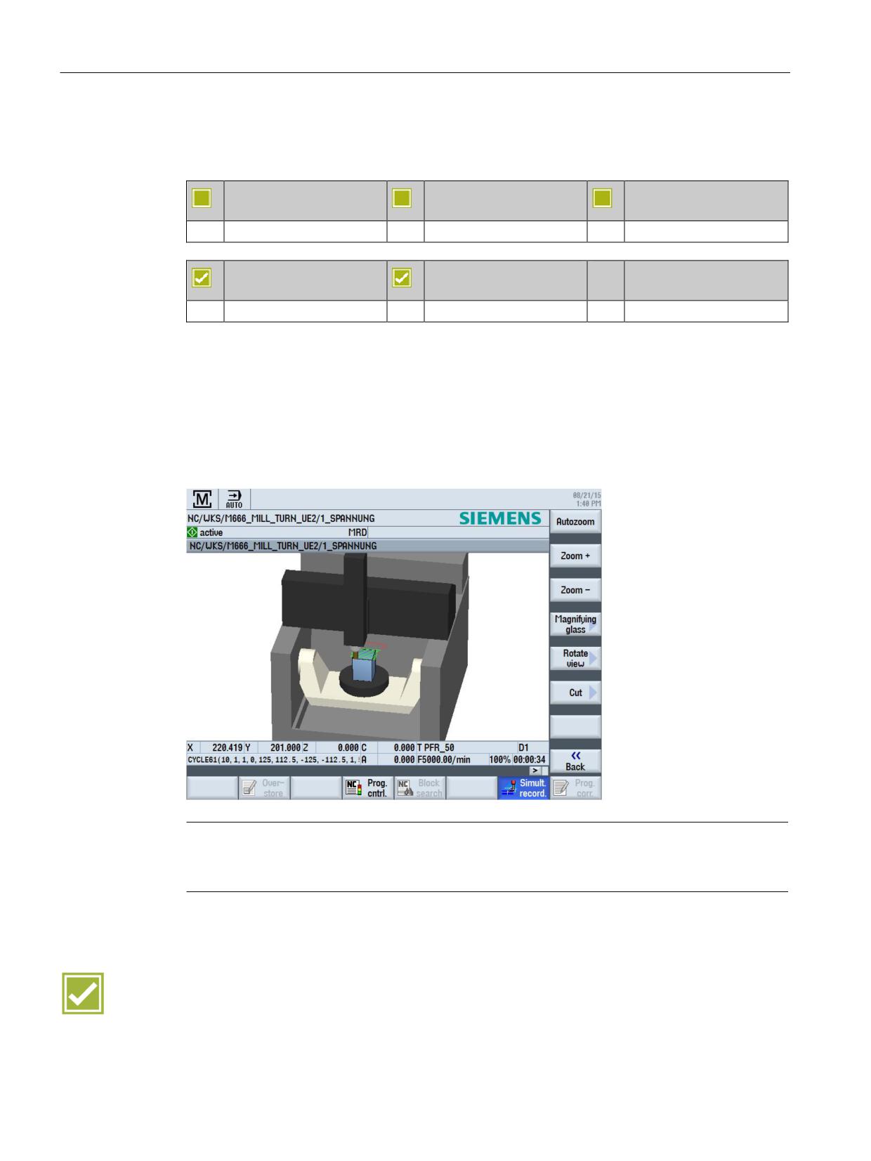
The SINUMERIK Collision Avoidance option provides optimum protection against
unintentional collisions of moving machine components with stationary machine
components.
You can active the collision monitoring in the Machine operating area for the JOG, MDA and
Automatic operating modes.
The Automatic operating mode provides for logging a 3D visualization of the collision
monitoring.
Note
The use of collision monitoring requires the availability of the relevant machine data and the
associated visualization.
Benefit
Ⴠ Collision monitoring also possible for complex machining operations, such as 5-axis
simultaneous milling or turning with B axis
SINUMERIK Operate - Milling
106
Control system overview for machine tools' sales people, 2017, A5E41992599B AA
Summary of unique selling points
18
18.1
SINUMERIK 828D
The SINUMERIK 828D operator panel control has the following notable features:
Compact
Ⴠ Rugged and maintenance-free design
Ⴠ All relevant functions at a glance on the 10.4"/15.6" color screen
Ⴠ Full-function QWERTY CNC keyboard for user-friendly programming at the machine
Ⴠ Full freedom of data transfer via USB, CF card and Ethernet, directly at the operator
panel
Powerful
Ⴠ
80-bit NANO floating-point accuracy for maximum precision of the workpiece results
Ⴠ Advanced Surface, a unique calculation procedure to improve the workpiece surface and
at the same time significantly reduce machining time
Ⴠ Powerful transformations for end faces and envelope faces of turned workpieces and
oblique machining of milling workpieces
Ⴠ Simple handling of tool and magazine data through clear and powerful tool management
Simple
Ⴠ Animated Elements: unique facility to display machining parameters with animated
sequences
Ⴠ ShopMill sequence programming: shortest programming times and clear CNC programs
with technological sequences
Ⴠ Common user interface for milling and turning
Ⴠ Easy Message: simple process monitoring by SMS
SINUMERIK Operate - Milling
Control system overview for machine tools' sales people, 2017, A5E41992599B AA
107
Summary of unique selling points
18.2 SINUMERIK 840D sl
18.2
SINUMERIK 840D sl
The SINUMERIK 840D sl control has the following outstanding features for milling
technology:
Open
Ⴠ Standard and integrated operator interface for milling, turning and additional technologies
Ⴠ Simple handling of tool and magazine data through clear and powerful tool management
Ⴠ Wide range of programming options using ShopMill machining step programming,
programGUIDE and DIN/ISO programming
Flexible
Ⴠ Optimum milling performance by being able to flexibly select the hardware that matches
the machine
Ⴠ High performance cycles for automatic workpiece and tool measurement
Ⴠ Optimum functional scope of SINUMERIK MDynamics, milling package for 3-axis and 5-
axis machining
Powerful
Ⴠ
80-bit NANO floating-point accuracy for maximum precision of the workpiece results
Ⴠ Top Surface offers enhanced surface quality, optimized dynamic response as well as
improved user friendliness, in particular for poor data quality from the CNC programs
provided by CAD/CAM systems
Ⴠ Simplest monitoring of 5-axis machines with a kinematic measuring cycle
SINUMERIK Operate - Milling
108
Control system overview for machine tools' sales people, 2017, A5E41992599B AA
Operating and Programming
Milling
Edition 2016.02
Training Manual
This document was produced for training purposes.
Siemens assumes no responsibility for its contents.
M552
General geometry basics
Sinumerik
Operate
Module Description:
This module explains the assignment of the axis and plane descriptions to the coordinate system of
the machine and also teaches the definition of points in relation to the work space.
Module Objective:
Working through this module you learn to understand the programming planes and also
how to specify points in a DIN conforming coordinate system.
Content:
Right hand rule
Explanation of the axis assignments
Points and distances in the work space
Programming planes
This document was produced for training purposes.
828D/840Dsl SINUMERIK Operate v4.7
Page 1
M552
Siemens assumes no responsibility for its contents.
General geometry basics
M552
General geometry
basics:
START
Right hand
rule
Explanation
of the axis
assignments
Points and
distances in
the work
space
Programming
planes
General geometry
basics:
END
Notes
828D/840Dsl SINUMERIK Operate
Page 3
M552
M552
General geometry basics
Right hand rule
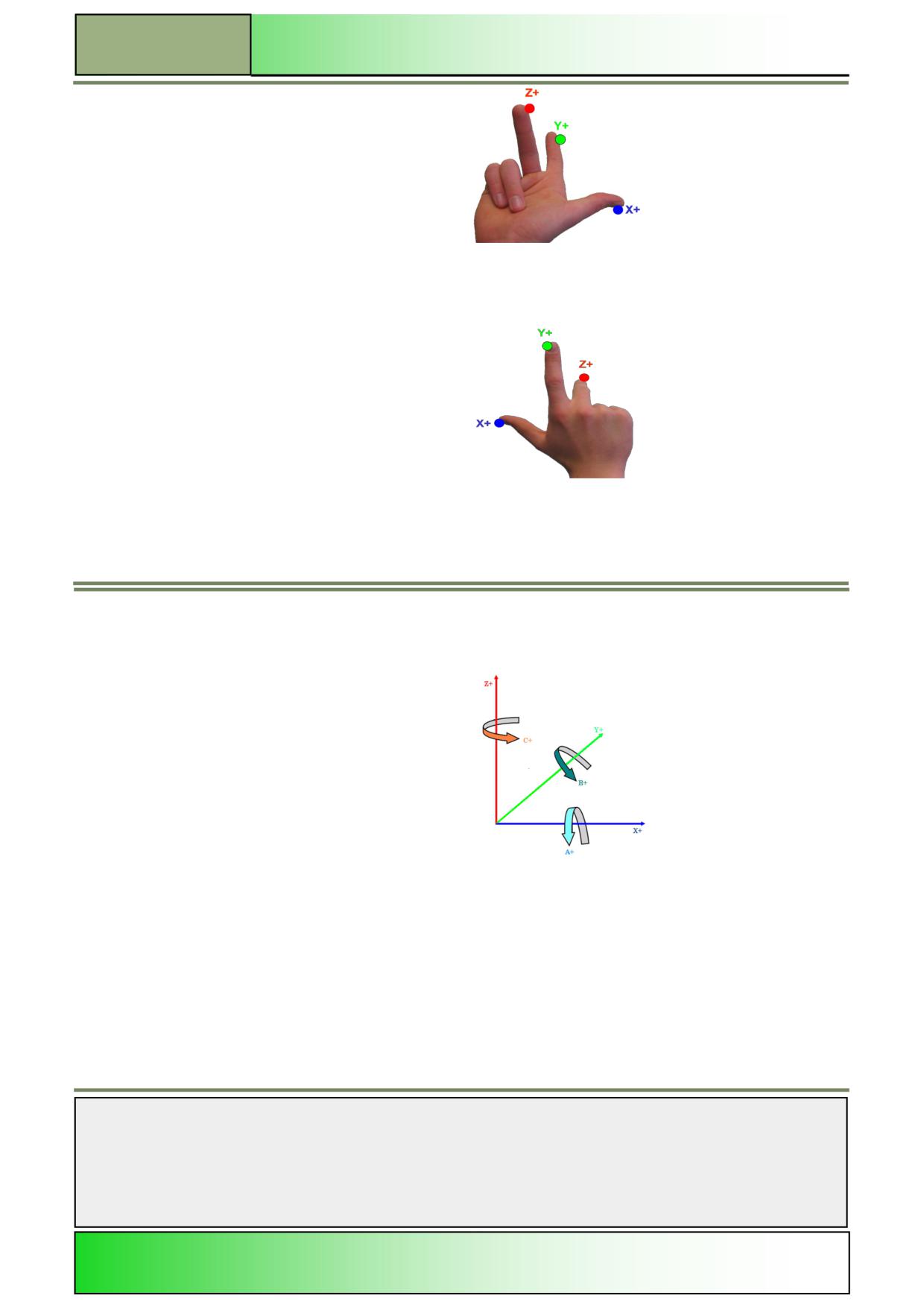
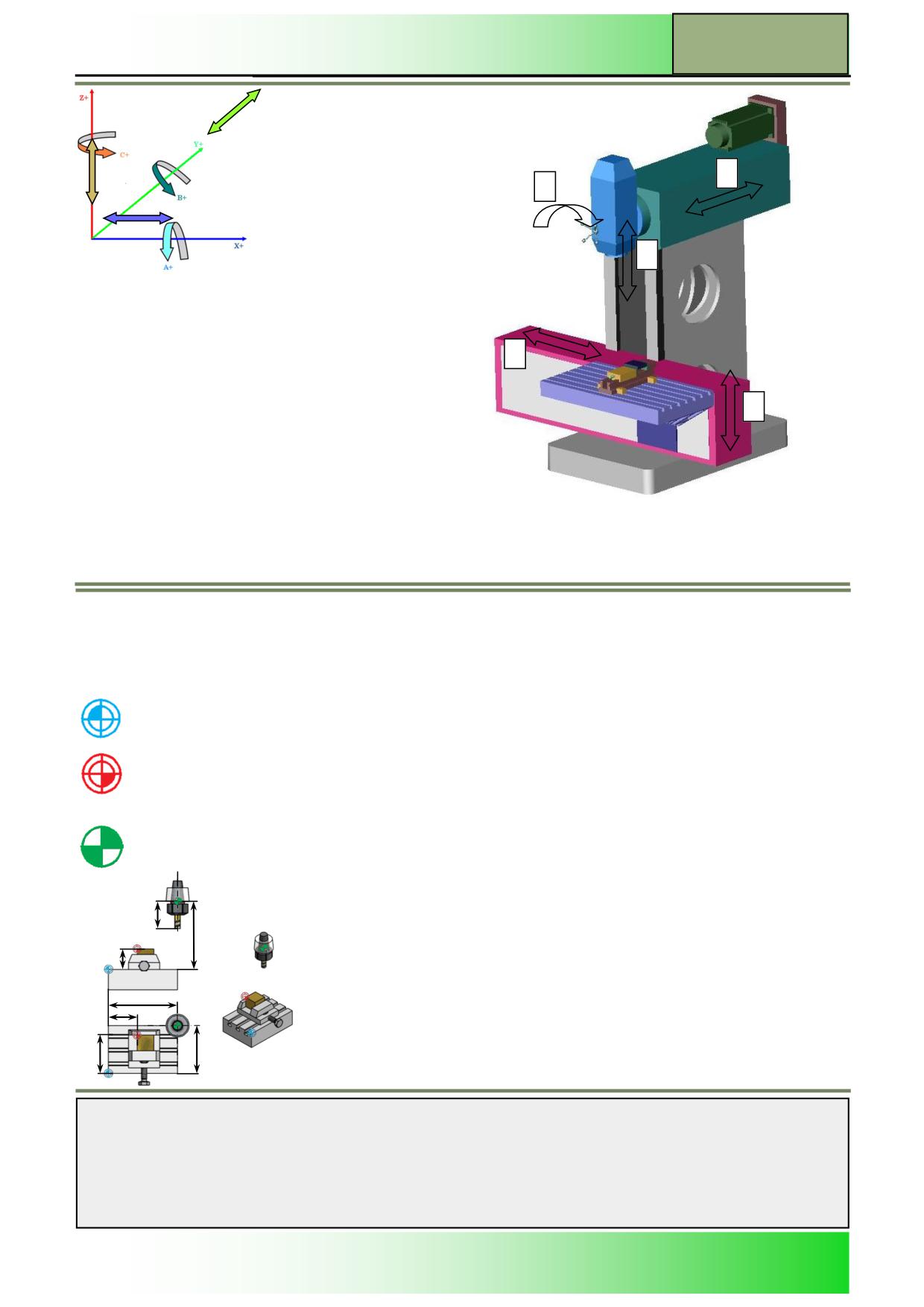
According to DIN standard the various axes of motion
within work space of CNC machines are addressed by
alphabets. The rules for the assignment of the axes are
determined in this DIN-standard.
The machine coordinate system that is derived from the
DIN-standard is the base for the geometrical description
of work pieces which allows us to clearly determine the
points in a plane or in space.
Vertical turning machine
The cartesian (rectangular) spatial coordinate system can
be best described with the “Right hand rule”. Here the
fingers of the right hand represent the axes: “X” (thumb),
“Y” (first finger) and “Z” (middle finger). The finger tips
point in the positive direction.
The position of the machine coordinate system is speci-
fied by the machine manufacturer keeping the following in
Horizontal milling machine
Definition of axis according to DIN-standard:
The DIN standard provides the following variants for such
cases.
Z-Axis: Is aligned parallel to the working spindle or
coincides with it. The positive direction points away
from the work piece. In case of more than one spindle,
one of them will be declared as the main spindle.
X-Axis: Is aligned parallel to the set-up plane or
coincides with it. If the Z-axis is vertical, the positive X-
axis is directed towards the right. If the Z-axis is hori-
zontal, the positive X-axis is directed towards the left.
Y-Axis: Is perpendicular to the X- and Z-axis, in such
a way that a spatial cartesian coordinate system re-
sults.
The direction “FROM” the work piece “TO” the tool is
Here the rotational axes A/B/C are associated with the X/
“PLUS”
Y/Z axes.
Looking in the positive direction of the linear axis, a clock-
Defining of axis within a workspace
wise rotation equals a positive rotation of the associated
rotary axis.
Explanation as per DIN 66217 or ISO 841:
However defining only three axes is not enough on mod-
ern machine tools. For instance if the milling head of a
milling machine is to be swivelled by a certain angle or the
quill of a tailstock is to be moved, a further definition of
these axes is required.
Notes
M552
Page 4
828D/840Dsl SINUMERIK Operate
General geometry basics
M552
W
Y
B
U
W
The axes U/V/W are parallel to the axes X/Y/Z.
The positive direction is that of the associated main axis.
X
Z
Points and distances within the work space
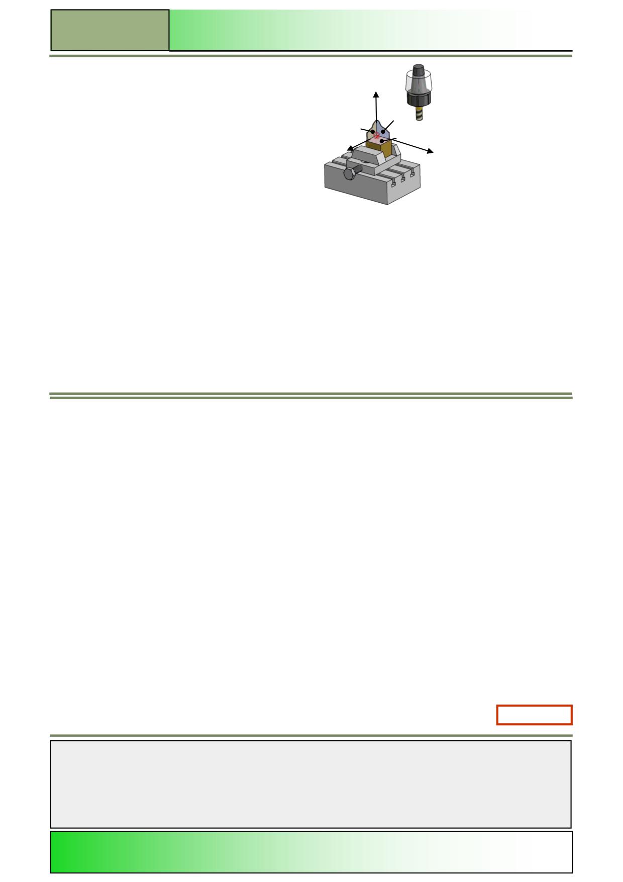
For the determination of all points within the work space, the control unit requires a zero point of the coordinate system. This
has been determined by the machine manufacturer. All other points have either fixed distances from the machine zero point
or else the distance must be defined.
The machine zero point (M) is determined by the machine manufacturer and cannot be altered. On
milling machines point is usually set on the work table, and on turning machines on the spindle flange.
The work piece zero point (W) is the origin of the work piece coordinate system. This can be speci-
fied by the programmer and should always be chosen in a way that the least calculation work is re-
quired to determine points on the contour given the dimensioning of the drawing. For turning work it
lies mostly on the turning axis and the right hand planar face.
The reference point (R) is approached for initializing the path measuring system, which means that at
this point all axes are set to zero. This is necessary since generally speaking the machine zero point
cannot be approached.
Notes
828D/840Dsl SINUMERIK Operate
Page 5
M552
M552
General geometry basics
Programming planes
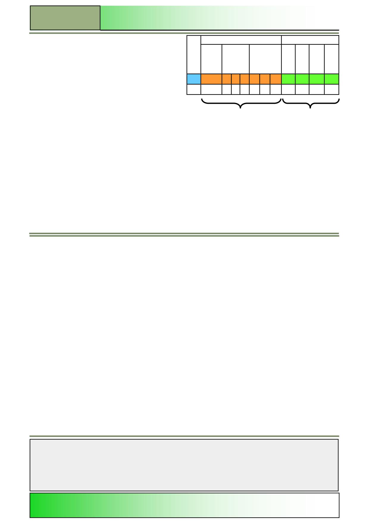
Continuous path control units can control slides and tool
+Z
carriers simultaneously along 2 or more axes at a pro-
grammed feed rate. For this the speed of the individual
drives must be matched to one another. This job is taken
G18
G19
over by the interpolator of the CNC-control unit. This is a
-Y
G17
software program for the evaluation of intermediate posi-
+X
tions and speed conditions of the individual axes such
that the slides can follow the programmed path. Starting
with a 2 ½-D Continuous path control unit the interpola-
tion can be switched between the three different planes.
A selection of the plane is made with the associated
programming
instruction:
XY-Plane - programming command G17
XZ-Plane - programming command G18
YZ-Plane - programming command G19
Note:
The standard plane being used for working with CNC-
Turning machines is G18. With CNC-Milling machines
the programming plane G17 is being used.
The working plane should either be programmed at the
beginning of the NC-program, or before programming
an operation in the relevant working plane.
The active programming plane is modal and remains
active until changed by another programming instruction.
M552: END
Notes
M552
Page 6
828D/840Dsl SINUMERIK Operate
M551
General technology basics
Sinumerik
Operate
Module Description:
This module explains the general layout of a program, with respect to the technological commands as
per DIN 66025 for turning and milling.
Module Objective:
Working through this module you become familiar with the most important technological
aspects and machine functions.
Content:
Layout of a CNC-program
Programming of the technology data
Switching commands
Summary
This document was produced for training purposes.
828D/840Dsl SINUMERIK Operate v4.7
Page 1
M551
Siemens assumes no responsibility for its contents.
General technology basics
M551
General
technological
basics:
START
Layout of a
CNC-program
Programming
of the
technology
data
Switching
commands
Summary
General
technological
basics:
END
Notes
828D/840Dsl SINUMERIK Operate
Page 3
M551
M551
General technology basics
Layout of a CNC-program
Departure information
Switching information
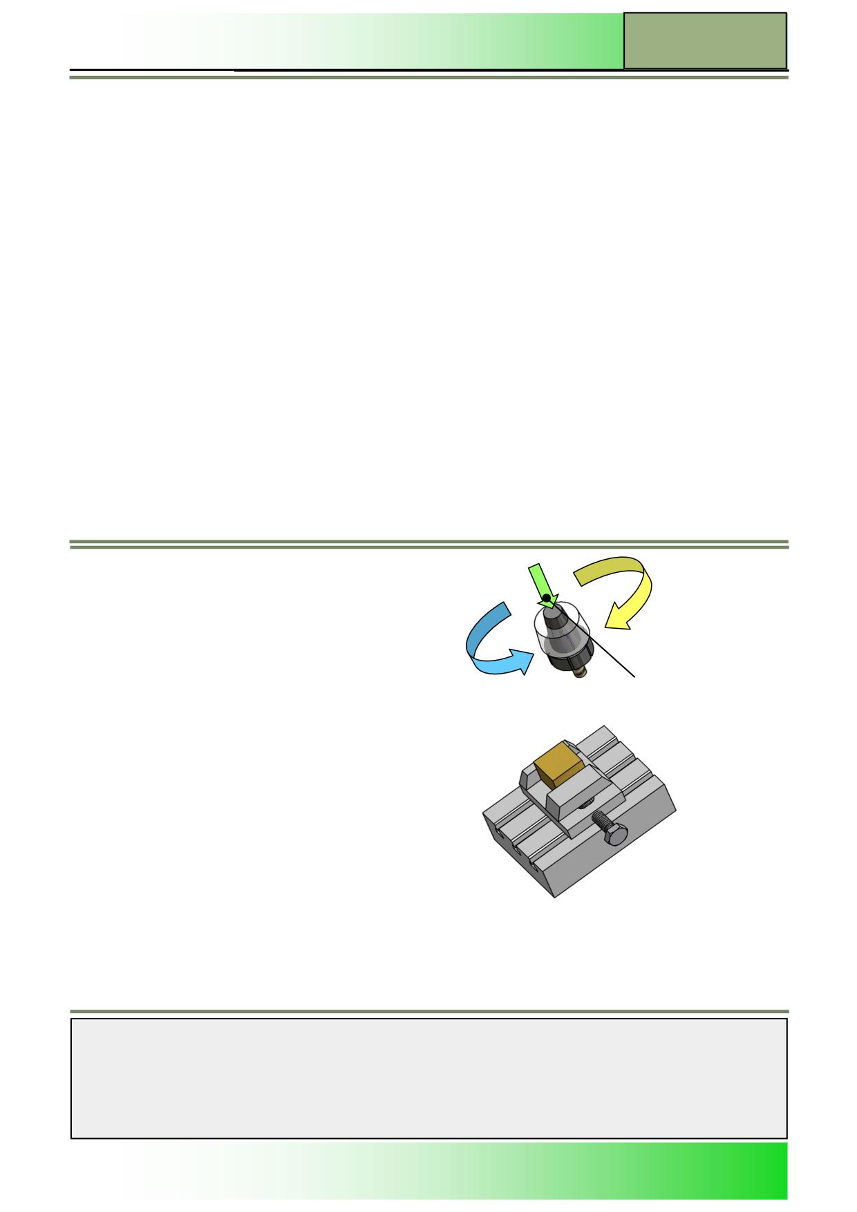
A CNC-program, also known as part program, consists of
Block
Nr..
Auxiliary
Coordinate
Interpolation
Misc.
a logical sequence of commands, which are executed step
Feed
Speed
Tool
command
axes
parameter
function
-by-step by the control unit after the program has been
started.
The manufacturers of control units recognize and apply the
N
G
X
Y
Z
I
J
K
F
S
T
M
guidelines as per DIN 66025.
Each program is compiled and stored under a program
name in the control unit. The name can contain letters as
well as numbers.
Geometrical data
Technological data
A block starts with a block number followed by the com-
mands.
Each command consists of command words, which in turn
consist of an address letter (A-Z) and an associated nu-
merical value (both upper or lower case characters are
permissible).
Programming of the technology data
Before every technological working step in a CNC-Program,
the respective tool must be selected by means of the ad-
The block number is a program-technical assignment,
dresses “T” and “D”.
which is not evaluated by the control unit as a command. It
is usually programmed to go up in steps of 10 and serves
The address “T” is followed by the name of the tool, which
the user only for a better oversight. It has no effect on the
may be stated either with numbers or letters (here only the
program execution.
variant using numbers will be dealt with).
The geometrical data include all instructions that clearly
All applicable tool data (e.g. tool type, length, radius, etc.) are
define mathematically the motion of the tool or the axes.
activated in the program with the address “D”.
Here a complete set of data “D“ is referred to as “Cutting
The technological data are used for instance to activate
edge”.
the required tool and to pre-select the necessary cutting
parameters feed rate and spindle speed. Miscellaneous
Several cutting edge numbers (D1 … D9) may be generated
functions can control for example such things as direction
for each tool.
of rotation and auxiliary appliances.
Programming example:
Explanation:
Programming example:
….
N10 T=“DRILL_12 mm“
Block 10, call-up of tool
N80 T1; Roughing tool
N20 M6
Block 20, Tool change,
N90 M6
N30 … D1
The cutting edge D... must
N100 G54 F0.2 S180 M4
be activated in the block
N110 G00 X20 Y0 Z2 D1
with the first axis movement.
N120
….
After the call-up of the tool, follows the selection of the opti-
In order to improve the overview within a program, com-
mum cutting values with the addresses “F” and “S”.
ments can be optionally added at the end of a block.
These must be preceded by a semi-colon; Any characters
The feed rate vf with the address “F” can be entered either as
that follow thereafter will not be taken account of by the
feed per min (in mm/min) or as feed per revolution (in mm/
Notes
M551
Page 4
828D/840Dsl SINUMERIK Operate
General technology basics
M551
The Cutting speed vc with the address “S” can be entered
Switching commands
either as spindle speed in revolutions per minute (rev/min) or
direct as cutting speed in meters per minute (m/min).
There are different commands to control the direction of
rotation of the work spindle.
Default status of the machine when they are powered up are
Additional auxiliary functions can for example control cool-
as follows:
ing circuits, clamping devices, auxiliary functions and run-
ning of the program.
Milling machines with feed rate “F” in mm/min
But the presence of these additional functions depends
Code G94
entirely on the technology and the machine design.
The following list should be only considered as an example
Deactivate constant cutting speed “S”
of commands:
Code G97
spindle speed in rev/min (default)
Instruction Meaning
M00
Programmed Stop
Programming example:
Explanation:
M03
Work spindle ON, clockwise
M04
Work spindle ON, anti-clockwise
N10 T=“HM_SF20mm“
M05
Work spindle Stop (however, the
N20 M6
program continues)
N30 G94 F200 S1000 M3 D1
vf = 200 mm/min, n =
M06
Tool change
1000 min-1
M08
Coolant ON
N40 ….
M09
Coolant OFF
M30
End of program; jump back to the start
of the program
Programming example:
Explanation:
M3
N10 T1=“Face mill”
N20 M6
Tool change
N30 G94 G97 F600 S2500 D1
vf = 600 mm/min, n =
2500 min-1
M4
N40 M3 M8
Spindle ON clockwise,
coolant ON
…..
Viewing direction
N90 M30
End of program
(Note: Further functions can be found in the annexure of this
manual)
Effect of the switching commands M3 and M4
Example Milling
Notes
828D/840Dsl SINUMERIK Operate
Page 5
M551
M551
General technology basics
Summary
Address
Meaning
M06
Tool change
Address
Meaning
T
Tool number
M08
Coolant ON
D
Cutting edge (tool data)
M09
Coolant OFF
F
Feed/Feed rate
S
Speed/Cutting speed
M17
End of subprogram
Path information/departure commands
M30
End of program, jump back to the begin-
ning of program
Instruction
Meaning
All instructions mentioned above are modal, until they are
G94
Linear feed in mm/min *
programmed to deactivate with different set of instructions.
G97
Spindle speed in min-1 *
Switching information
Instruction
Meaning
M00
Programmed stop
M03
Work spindle ON, clockwise
M04
Work spindle ON, anti-clockwise
M05
Work spindle Stop
M551: END
Notes
M551
Page 6
828D/840Dsl SINUMERIK Operate
M556
Program structure
Sinumerik
Operate
Module Description:
This module describes the programming structure of NC-programs.
Module Objective:
In this module you learn how to structure a part program clearly and functionally.
Content:
Basic principles of programming
Program structure of a part program
Program structure of a machining sequence
This document was produced for training purposes.
828D/840Dsl SINUMERIK Operate v4.7
Page 1
M556
Siemens assumes no responsibility for its contents.

Program structure
M556
Program structure:
START
Basic
principles of
programming
Program
structure of a
part program
Program
structure of a
machining
sequence
Program structure:
END
Notes
828D/840Dsl SINUMERIK Operate
Page 3
M556
M556
Program structure
Basic principles of programming
Program structure of a part program
Certain principles should be followed during the crea-
tion of part programs:
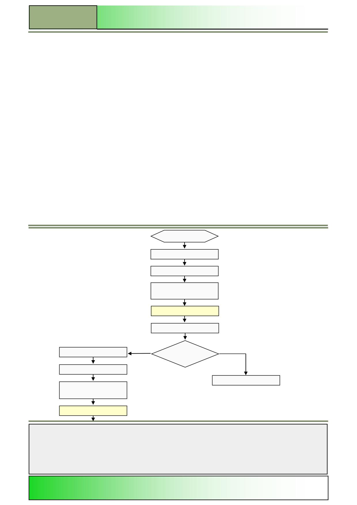
The following flow chart represents a possible suggestion
for a suitable structure of the main program.
The program must ensure that an unlimited number of
work pieces can be produced with the quality
(tolerances, surface quality, form and position deviation,
etc.) required on the drawing with a minimum of produc-
tion time and the least possible material wastage.
It is always the motion of the tool along the drawn ideal
contour of the work piece.
If tolerances are shown, the programming is always
referred to the middle of the tolerance.
Example: Æ20 + 0,1 - programmed value = 20,05.
Precise dimension corrections can be carried out on the
machine by means of the wear correction feature for
the tool.
The program should exhibit a clear and concise struc-
ture and should contain comments wherever possible to
ensure that other users can understand the layout easi-
ly at later stages.
Program header
Tool call-up 1
Technology block
Approaching the safety
level with the tool
Machining sequence 1
Retraction of the tool
no
yes
Workpiece
Tool call-up 2
finished
Technology block
End of program
Approaching the safety
level with the tool
Machining sequence 2
Notes
M556
Page 4
828D/840Dsl SINUMERIK Operate
Program structure
M556
Program structure of a machining sequence
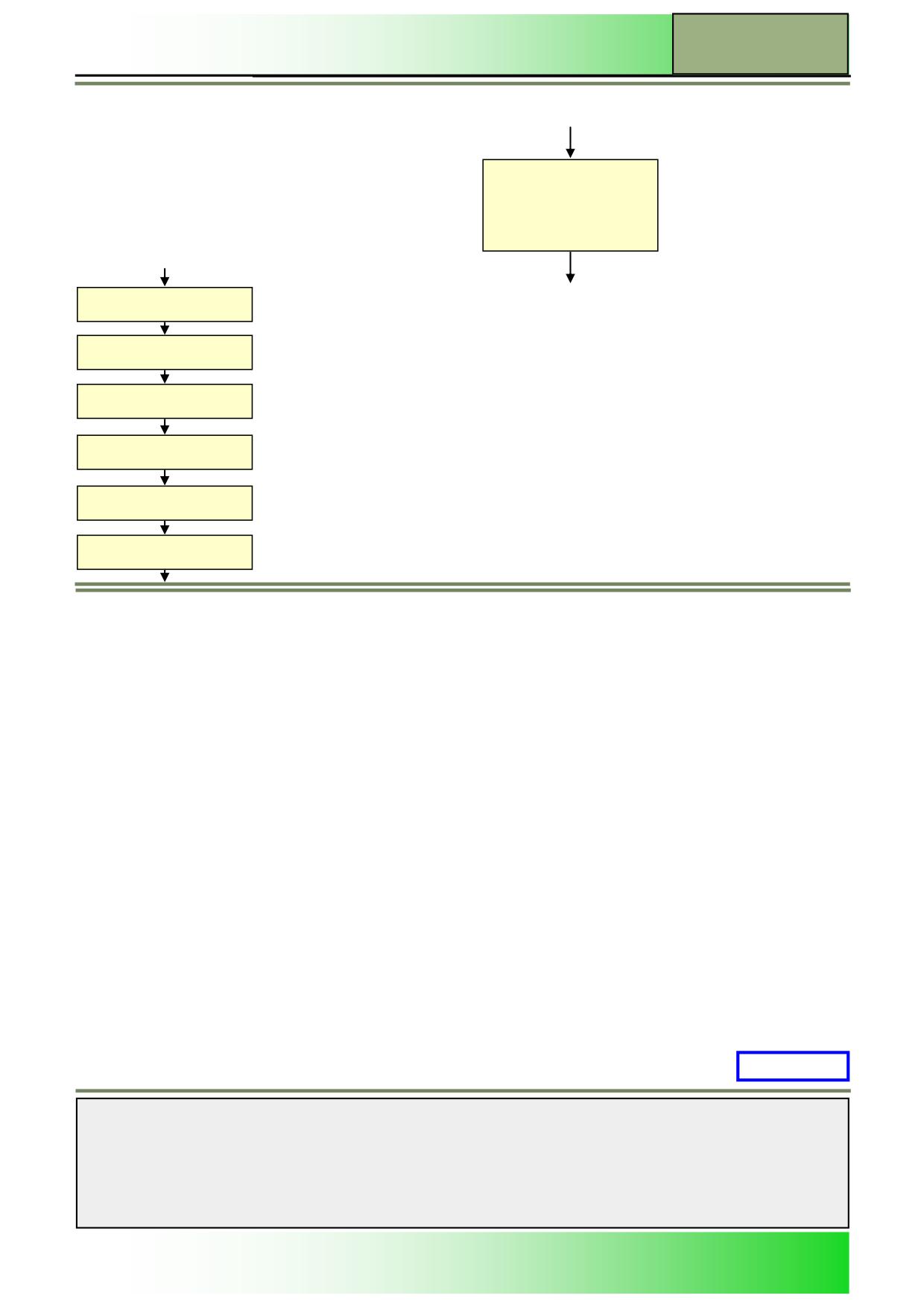
Programming using cycles
The programming of the machining sequence can be
achieved by means of description of the individual steps
using departure commands (e.g. G00, G01, G02, etc.) or by
Input of the individual pa-
means of machining cycles.
rameters using the input
The following representation refers to the flow chart in sec-
mask and graphical sup-
tion 2 of this manual and describes a possible machining
port
sequence.
Programming with G-Codes
Activation of radius correc-
tion
The following criteria should be kept in mind when select-
ing between the two described possibilities:
Interpolation to the first
destination point
Availability of the cycles on the respective machine.
Interpolation to the next
Machining time required with cycles or with G-codes.
destination point
The relation of the number of work pieces to the re-
quired programming extent.
Interpolation to the last des-
tination point
Deactivation of the radius
correction
M556: END
Notes
828D/840Dsl SINUMERIK Operate
Page 5
M556
M566
Operating elements
Sinumerik
Operate
Module Description:
The general operation of a Sinumerik Operate will be described.
Depending on the machine manufacturer the following operating elements can be used:
Operator panels (OP)
CNC-full keyboard
Machine control panel (MCP)
Module Objective:
With help of this module you learn to recognise general operating elements of the Sinu-
merik Operate, and how to differentiate them from one another.
Content:
Operator panel layouts of the Sinumerik Operate
CNC-full keyboard
Machine control panel
This document was produced for training purposes.
828D/840Dsl SINUMERIK Operate v4.7
Page 1
M566
Siemens assumes no responsibility for its contents.

Operating elements
M566
Operating elements:
START
Operator panel
layouts of the
Sinumerik
Operate
CNC-full
keyboard
Machine
control panel
Operating elements:
END
Notes
828D/840Dsl SINUMERIK Operate
Page 3
M566
M566
Operating elements
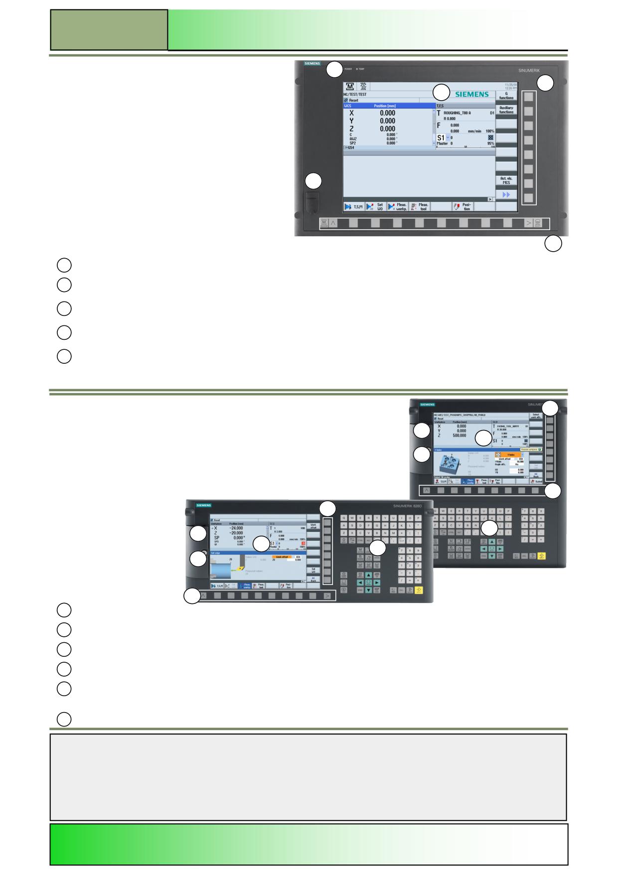
The operator panel (OP) consists of the following oper-
5
ating elements:
2
3
Membrane keyboard with 8 + 4 horizontal and 8
vertical softkeys
Colour display (10.4” Display on 828D, 15” Dis-
play on 840D sl)
Front-USB-plug on operator panel front (840D sl),
USB, CF-card, Ethernet on operator panel front
4
(828D)
Fully integrated QWERTY CNC-keyboard (828D)
Operator panel layout of the Sinumerik 840D sl:
1
1
Horizontal softkey strip (HSK) with 4 screen keys (2 each located on the left and right side)
2
Vertical softkey strip (VSK)
3
15“ TFT-colour display
4
Front-USB-plug (Sinumerik 840D sl) , e.g. for connection of external memory media, mouse or keyboard
5
Status-LED: Power
Status-LED: Temp
Operator panel layout of the Sinumerik 828D
2
5
3
4
1
2
6
5
3
6
4
1
1
Horizontal softkey strip with 4 screen keys (2 each located on the left and right side) (HSK)
2
Vertical softkey strip (VSK)
3
10,4“ TFT-colour display
4
USB, CF-card and Ethernet on panel front behind removable cover
5
Ready-LED (Status red/green), NC-LED (Status LED of the NC) and CF-LED (write/read access on CF-card)
behind lockable and removable cover
6
Integrated QWERTY CNC-keyboard
Notes
M566
Page 4
828D/840Dsl SINUMERIK Operate
Operating elements
M566
Horizontal and vertical Softkey bar (HSK/VSK)
Softkeys are buttons, which are dynamically linked with programmed functions. These functions are presented on the moni-
tor above the softkey bar (HSK) or to the left of the softkey bar (VSK) as a strip of icons.
The 8 horizontal softkeys are used to access the individual operation sectors including further menu layers. There is an
associated vertical menu strip/Softkey strip for each of the horizontal menu points.
The 8 vertical Softkeys are functions associated with the presently selected horizontal Softkey.
The function will be called up when the vertical softkey is pressed.
The content of the vertical softkey bar can therefore change once again if a sub-function to the selected function is cho-
sen.
The horizontal softkey bar consists furthermore of:
4 screen keys (see pictures below)
“MACHINE”-key:
Calls-up the operating area “MACHINE” (in operating mode “JOG”, “MDA” or “AUTO”).
“Recall”-key:
Jumps to the next highest menu level.
“Extend”-key:
Extends the horizontal softkey bar.
“MENU SELECT”-key:
Calls the main menu for operating area selection.
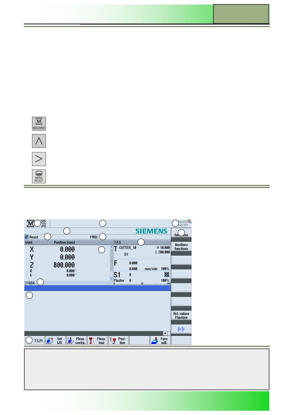
Screen area
The screen is laid out as follows:
1
4
12
2
9
3
5
8
6
7
10
11
Notes
828D/840Dsl SINUMERIK Operate
Page 5
M566
M566
Operating elements
1
8
Operation sector
Display of:
2
T = Active tool
Program path and name
3
F = Present feedrate
Status, program influence and program name
4
S = Actual spindle revolution
Alarm and message line
Spindle load factor in percent
5
Channel operation messages
9
Vertical softkey bar (VSK)
6
Position readout for the axes
10
Working window
7
Display of the active zero point and rotation
11
Horizontal softkey bar (HSK)
12
Date and Time
CNC-full keyboard
According to the model of operating panel that is used, a CNC-keyboard can be integrated for operation and programming.
The keys that are described here can also be located directly on the operator panel.
The layout of the operating panel is described in the documentation of the machine manufacturer.
Below follows a description of the basic keys of the CNC-Full keyboard.
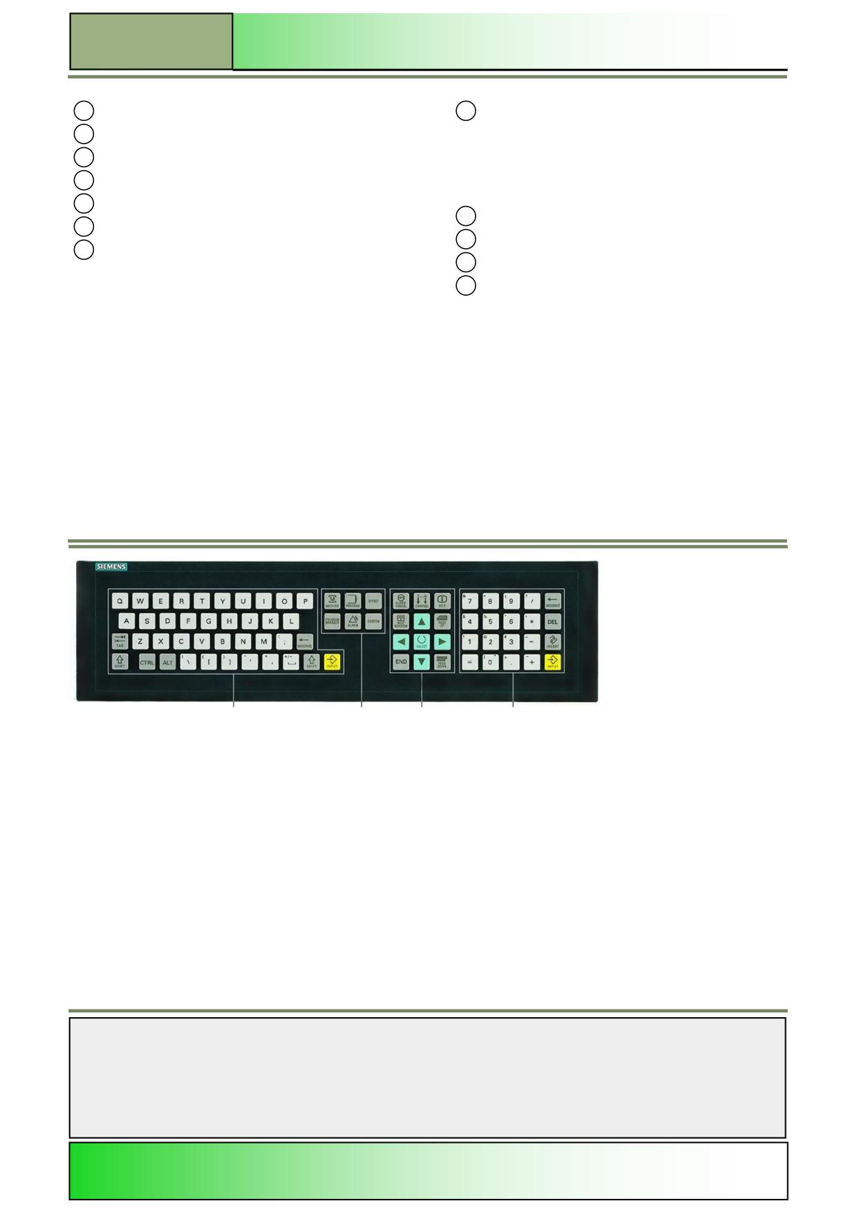
CNC-Full keyboard “KB 483”:
Alpha-Block
Hotkey-Block Cursor-Block Number-Block.
Alpha-Block:
The alpha-block features the letters A, ..., Z, the space key and the special character for the input
of text.
Hotkey-Block:
The hotkey-block serves the direct selection of operation areas.
Cursor-Block:
The cursor-block is used for navigation around the screen display.
Number-Block:
The number-block features the numbers 0 ... 9, the decimal point and special characters for the
input of numerical characters and operators.
Notes
M566
Page 6
828D/840Dsl SINUMERIK Operate
Operating elements
M566
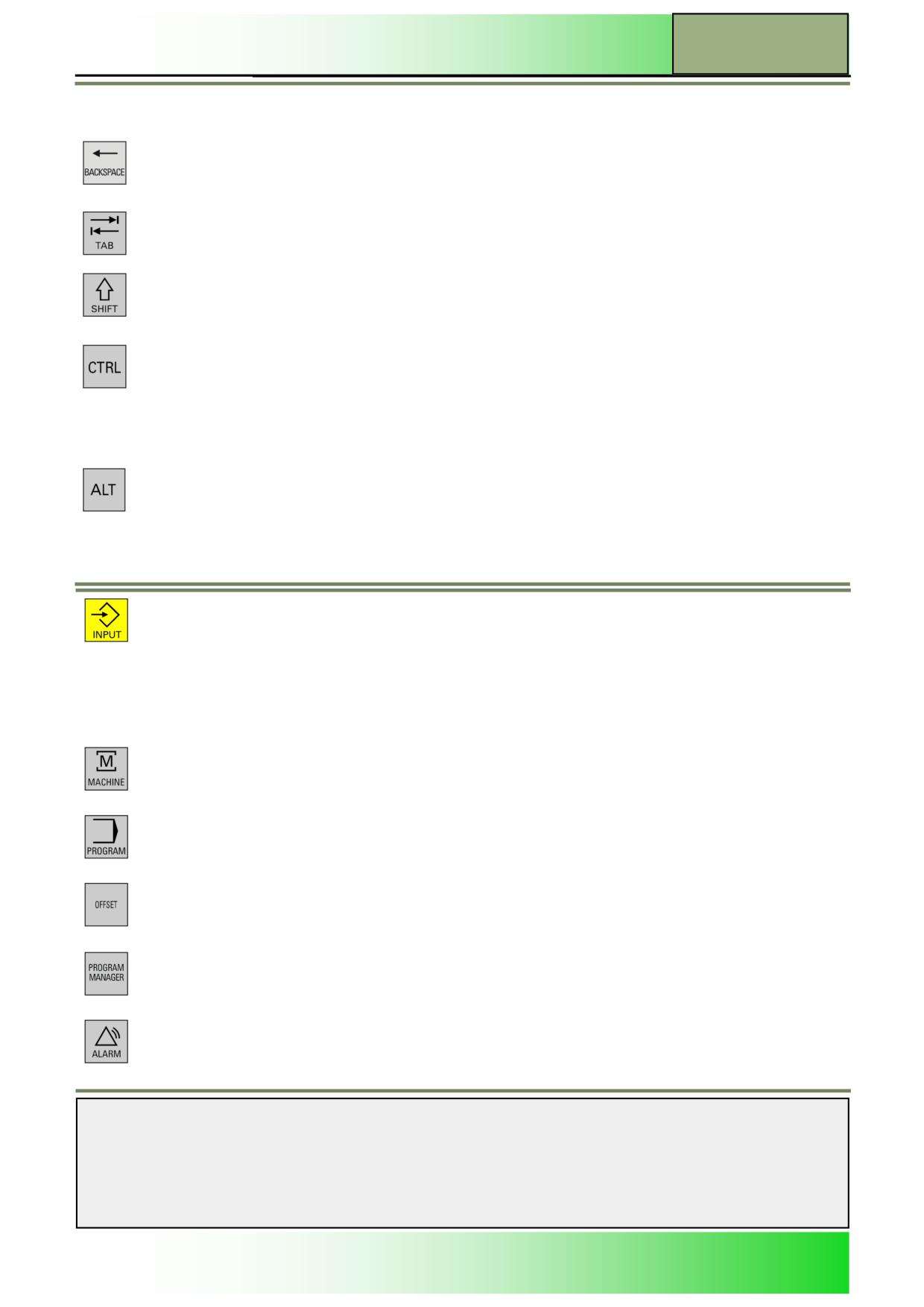
Keys in the Alpha-Block
BACKSPACE
Clears a value in the input field.
If in edit mode, the character in front of the cursor will be cleared.
TAB
Indent the cursor by several characters.
SHIFT
If the Shift-key is held depressed, the upper character on keys with double usage will be entered.
CTRL
With the following key combinations navigation in the work plan and the G-Code-Editor is carried
out:
Ctrl + NEXT WINDOW: Jump to the beginning.
Ctrl + END: Jump to the end.
ALT
ALT-Key
INPUT
Accepts an edited value
Opens / closes a directory
Opens a file
Keys in the Hotkey-Block
MACHINE
Opens up the operating area "Machine" (JOG, MDA, Auto). Corresponds to the yellow HSK 1
“Machine”
PROGRAM
Opens up the operating area "Program".
The key corresponds to the yellow HSK 3 “Program”.
OFFSET
Opens up the operating area "Parameter” (Tool list, Tool wear, Magazine, Work offset, User
variable, Setting data). The key corresponds to the yellow HSK 3 "Parameter".
PROGRAM MANAGER
Opens up the operating area "Program manager“.
The key corresponds to the yellow HSK 4 "Program Manager".
ALARM
Opens up the actual Alarmlist-window.
The key corresponds to the VSK 1"Alarm list" in the operating area “Diagnostics”.
Notes
828D/840Dsl SINUMERIK Operate
Page 7
M566
M566
Operating elements
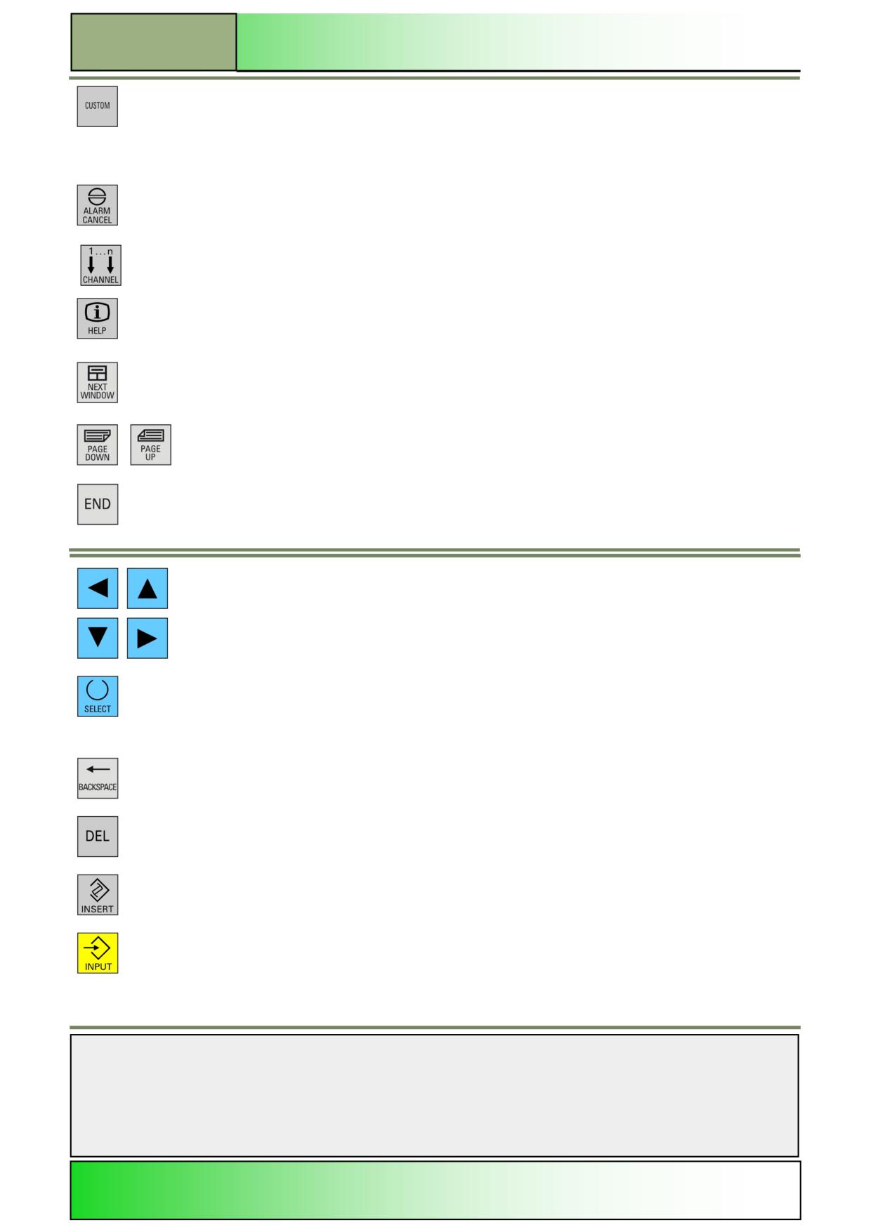
CUSTOM
This key can be customized by the machine manufacturer.
See the machine manufacturer’s documentation .
Keys in the Cursor-Block
ALARM CANCEL
Clears an active alarm shown in the alarm and message line that is identified with this symbol.
CHANNEL
Selects a channel from 1 - n.
HELP
Opens the context-sensitive help window in a split-screen view. In case of the G-Code editor
the help documentation with intelligent support for programming instructions is called up.
NEXT WINDOW
Activates the next subwindow in the actual working window. By pressing “CTRL + NEXT WIN-
DOW“ in the G-Code editor window you can jump to the first line of the program code.
PAGE UP or PAGE DOWN
Paging up or down in a directory or the work plan.
END
Locates the cursor in the last input field of a parameter mask. In the G-code editor the cursor will
be set to the end of the active line and by pressing STRG + END the cursor jumps to the end of
the last line of the program.
Cursor-Keys
Navigates through the various fields or lines on the screen.
While in a program listing, the “cursor-to-the-right”-key opens a directory or a program. To
change to the next level above the present level press the “cursor-to-the-left”-key.
SELECT
With this key you can select amongst several given alternatives.
Keys in the Number-Block
BACKSPACE
Clears a value in the active input field.
While in the edit mode, just the character in front of the cursor will be cleared.
DEL
Deletes the value in the parameter field.
While in the edit mode, just the character behind the cursor will be deleted.
INSERT
Activation of the insertion mode or the pocket calculator. Opens a parameter menu in an input
field if available.
INPUT
Accepts an edited value
Opens/closes a directory
Opens a file
Notes
M566
Page 8
828D/840Dsl SINUMERIK Operate
Operating elements
M566
Machine control panel
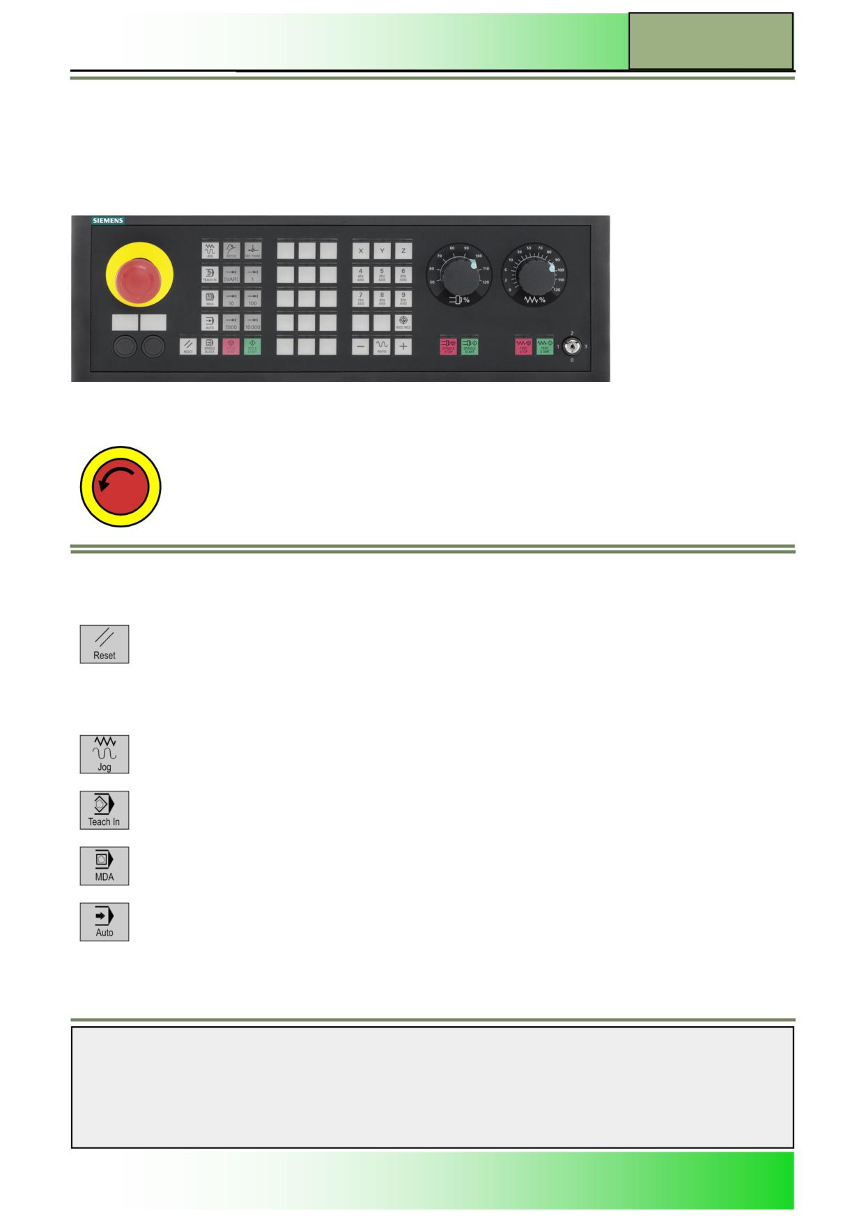
Depending on the type of operating panel the machine manufacturer may be using either a SIEMENS or his own machine
control panel for the operation of the machine.
This section describes the standard-keys of the Siemens machine control panel.
Depending on the machine further keys may be used; such information should be taken from the documentation by the
machine manufacturer.
Below follows a description of the keys of the machine control panel and their function:
EMERGENCY-STOP-key
Press this key in the case of an emergency, i.e. if human life is endangered or if the machine or
work piece could be damaged.
All drives will be braked to a standstill with the greatest possible braking torque.
Note:
For further reactions that may be caused by pressing the EMERGENCY-OFF key please refer
to the documentation by the machine manufacturer.
RESET
Stops the machining from executing the presently running program. The NC-control unit
remains synchronized with the machine. It is now in the basic condition ready to commence
a new program run.
Clears an active alarm.
JOG
Selection of the operating mode “JOG”.
TEACH IN
Creation of programs in interactive mode with the machine.
MDA
Selection of the operating mode “MDA” (Machine Data Automatic).
AUTO
Selection of the operating mode “Machine Auto”.
Notes
828D/840Dsl SINUMERIK Operate
Page 9
M566
M566
Operating elements
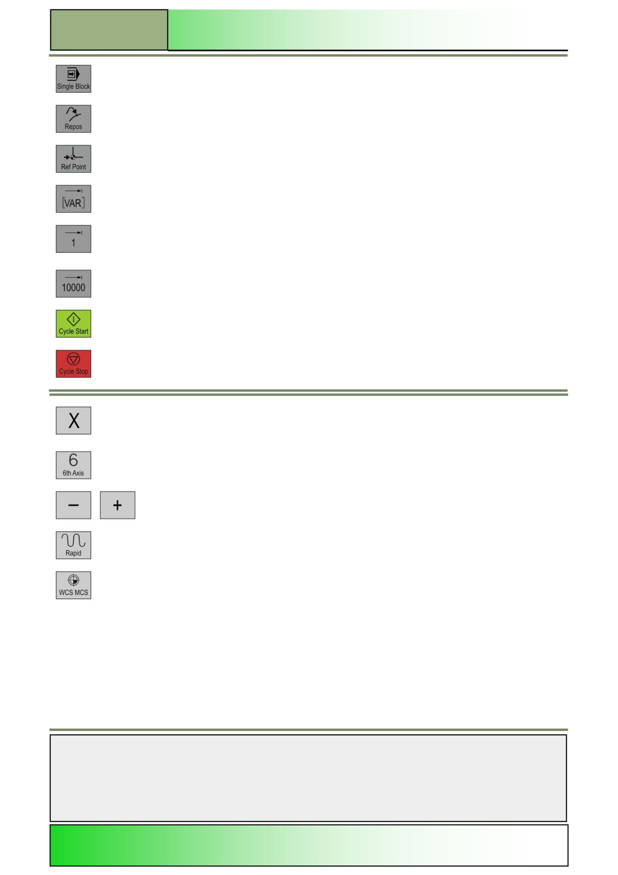
SINGLE BLOCK
Runs a program block-by-block (single block).
REPOS
Repositions and re-approaches a contour.
REF. Point
Approaches a reference point.
VAR (Variable JOG step)
Traverse through an incremental dimension with variable step lengths.
Inc (Incremental JOG step)
Traverse through an incremental dimension with a given step size of 1, ..., 10000 increments.
The actual length of an incremental step depends on a machine datum.
Note:
Read the machine manufacturer’s documentation.
CYCLE START
Starts a program run.
CYCLE STOP
Stops a program run.
Axis keys
Axis (X, Y, Z, 4, 5, 6) selection.
to
Direction keys
For traversing an axis either in the positive or negative direction.
RAPID
For traversing an axis at rapid traverse rate (fastest speed).
WCS MCS
Toggling between the work piece coordinate system (WCS) and the machine coordinate system
(MCS).
Notes
M566
Page 10
828D/840Dsl SINUMERIK Operate
Operating elements
M566
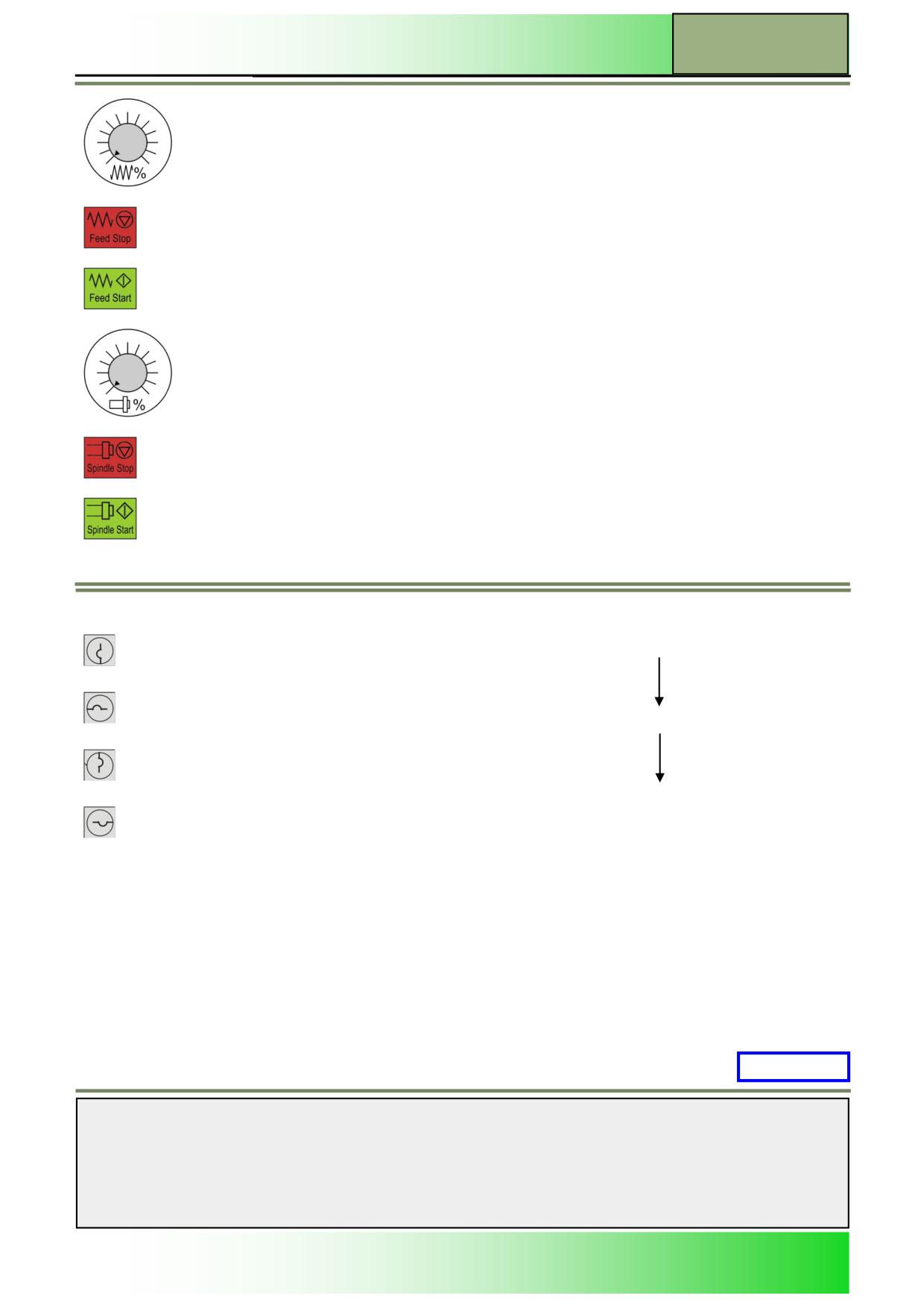
Feed / Rapid traverse override
For increasing or reducing the programmed feedrate. The programmed feedrate is represented
by 100% and can be varied within the range of 0% to 120%, in rapid traverse only up to 100%.
The new adjusted value appears as an absolute and percentage value in the feed status dis-
play on the screen.
FEED STOP
Stops the machining of the currently running program, in order to stop the axes.
FEED START
Continuation of the program as from the present block and to increase the feedrate to the pro-
grammed value.
Spindle override
For increasing or reducing the programmed speed. The programmed speed corresponds to
100% and can be varied within the range of 0% to 120%. The new value thus selected ap-
pears as an absolute value and as a percentage in the speed status display on the screen.
SPINDLE STOP
To stop the spindle.
SPINDLE START
To start the spindle.
Key switch
Lowest access
Position 0
stage
No key
Access stage 7
Position 1
Key 1 black
Increasing access rights
Access stage 6
Position 2
Key 1 green
Access stage 5
Highest
Position 3
access right
Key 1 red
(Key switch)
Access stage 4
Further access rights (Access stage 3 - 0) are possible by means of passwords.
M566: END
Notes
828D/840Dsl SINUMERIK Operate
Page 11
M566

M566
Operating elements
Notes
M566
Page 12
828D/840Dsl SINUMERIK Operate
M568
Basics of operation
Sinumerik
Operate
Module Description:
This module describes the relevant parts of the main screen with help of the basic screen layout.
In addition to the topic above, this module covers the selection of parameters with respect to units
(mm/inch) used and the usage of the calculator within the input masks.
Module Objective:
In this module you learn about the screen layout of the display panel of the Sinumerik
Operate, as well as the the basic operation of the control using softkeys and buttons.
Content:
Basics of operation
Considerations for the input masks
This document was produced for training purposes.
828D/840Dsl SINUMERIK Operate v4.7
Page 1
M568
Siemens assumes no responsibility for its contents.
M568
M568
Page 2
828D/840Dsl SINUMERIK Operate
Basics of operation
M568
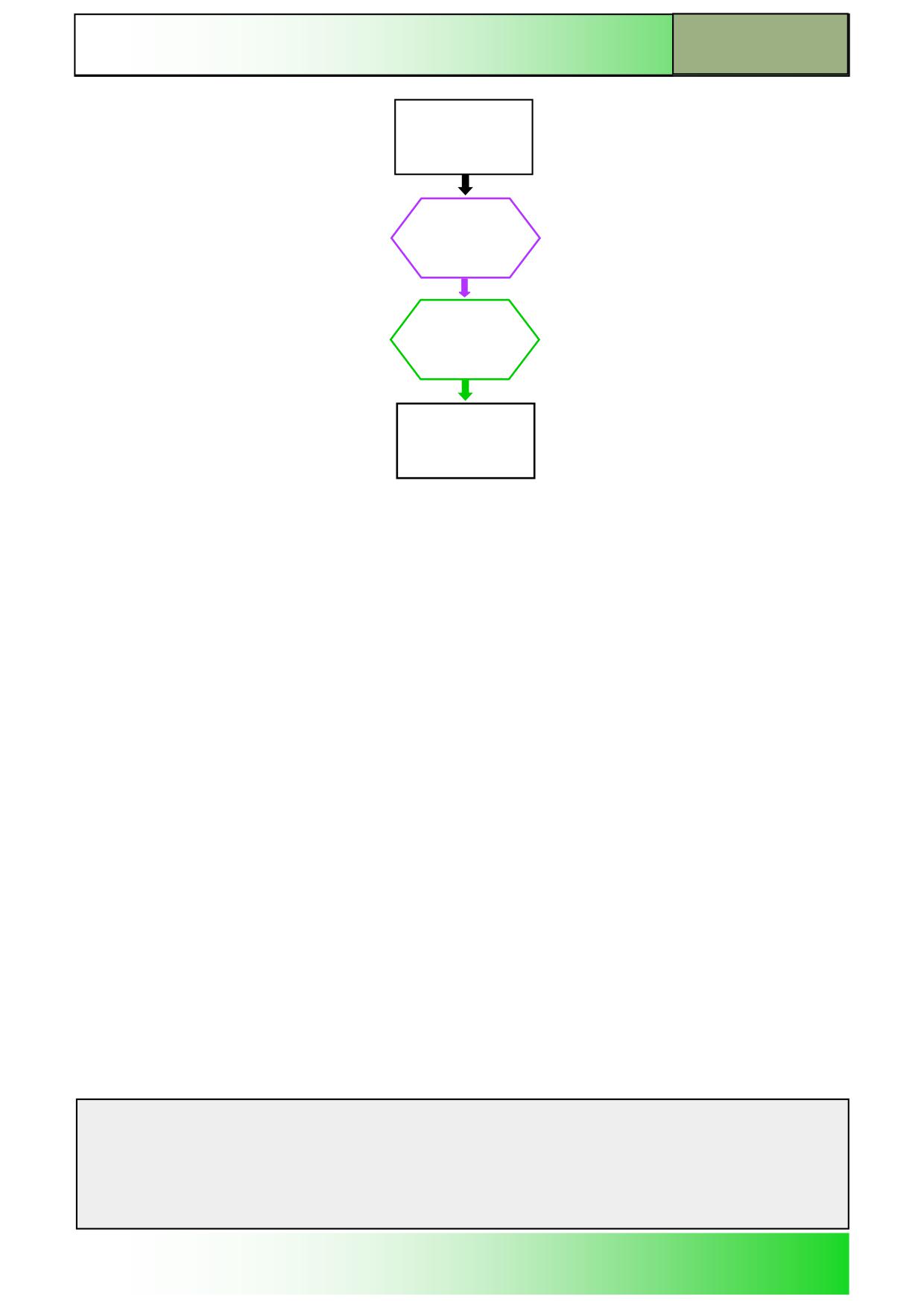
Basic operations:
START
Basics of
operation
Consideration
s for the input
masks
Basic operations:
END
Notes
828D/840Dsl SINUMERIK Operate
Page 3
M568
M568
Basics of operation
Basics of operation
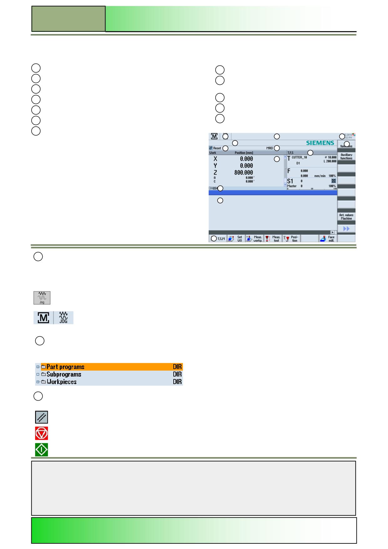
Main screen of the HMI in the operating mode “JOG”
1
Active operating area and mode
8
Position readout for the axes
2
Program path and name
9
Display of the active zero
3
point, rotation, mirroring and scaling
Status, program influence and channel name
10
4
Working window
Alarm and message line
11
5
Horizontal softkey bar
Channel operation messages
12
6
Vertical softkey bar
Date and time
7
Display of:
1
4
6
T = Active tool
2
1
3
5
F = Present feedrate
7
S = Spindle
8
Spindle load factor in percent
9
1
1
1
Active operating area and operating mode
(The display mode depends on the selected operating mode on the machine control panel (MCP)).
Display area
Description
The operating mode “Machine Manual” (setup mode) can be selected by pressing the
“JOG” button on the machine control panel.
Functions adjusted under “T,S,M“ like tool selection, work offset and spindle control
affect all movements in the manual operating mode.
Another function using the “JOG“ Mode is the approaching of the reference point
(REF.POINT).
2
Program path and name
NC programs can be created, modified and selected in the three main directories on the NC of the type DIR.
3
Status, program influence and channel name
Display area
Description
Reset
Interrupted
Activated
Notes
M568
Page 4
828D/840Dsl SINUMERIK Operate
Basics of operation
M568
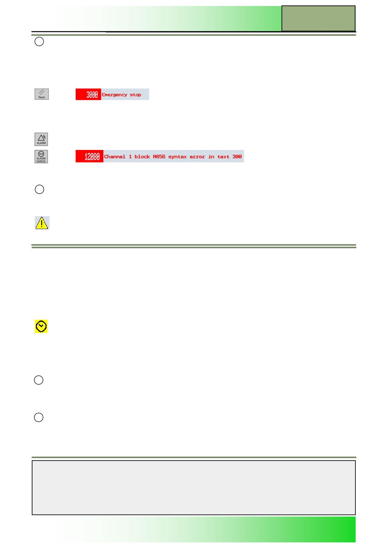
4
Alarm and message line
In case of a syntax error in the program code or a hardware malfunction (e.g. emergency stop) an alarm number with ex-
plaining text shows up.
MCP
Display area
Description
After correcting the error (correction of the hardware malfunction) you can reset the error
message with the “RESET“ button.
CNC-keyboard
By pressing the “ALARM“ key on the keyboard the “Alarm list” window shows up, with a
list of all active alarm messages.
After correcting the error (correction of the syntax error) you can reset the error message
with the “ALARM CANCEL“-key on the keyboard.
5
Chanel operation messages
Display of operation messages with symbols.
Display area
Description
Attention: In case of conditions with this symbol a manual operation is required.
Operation in case of the message “Stop“:
After the fault remedy the machining program will be continued after pressing “NC-Start“.
Operation in case of the message “Wait“:
After a successful acknowledgement of the fault the machining program will be continued
automatically.
Stop: EMERGENCY STOP activated
Stop: M0/M1 activated
In case of conditions with this symbol, a manual operation is usually not
necessary.
Wait: Remaining dwell time in seconds or in spindle revolutions
Wait: Exact stop not reached
Wait: for positioning axis
6
Date/Time
Current date and time are shown in the upper right corner of the screen.
7
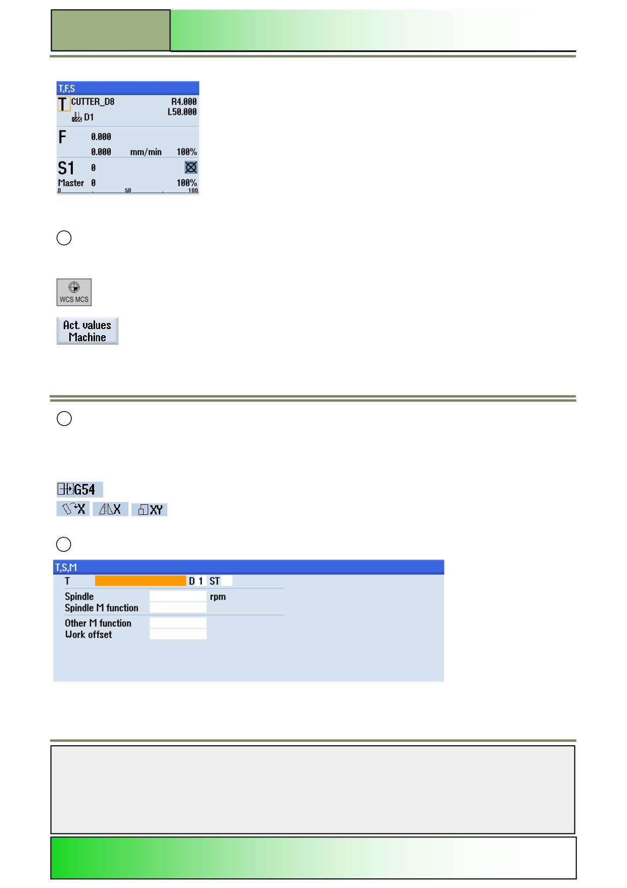
Display of T,F,S and spindle-value
Notes
828D/840Dsl SINUMERIK Operate
Page 5
M568
M568
Basics of operation
Display area
Description
T: (Tool) Name of the active tool. The optional display of “TC“ is only
available if a swivel head table is present.
F: (Feed) Display of the active feed rate for the current machining
(top: actual feed rate, large digits during machining), as well as the
display of the programmed feed rate (bottom) and the feed over-
ride in %.
S: (Spindle) Display of the active spindle speed for the current ma-
chining (top: actual speed, large digits during machining), as well
as the display of the programmed spindle speed (bottom) and the
speed override in %.
8
Position display for the axes
MCP/Display area
Description
With the key “WCS MCS” on the MCP or the VSK 7 “Act. values. Machine” it is
possible to switch between the machine coordinate system (MCS) and the workpiece
coordinate system (WCS).
9
Display of the active zero point offsets, rotation, mirroring and
scaling
The machine coordinate system (MCS) does not consider zero point offsets in comparison to the workpiece coordinate
system (WCS).
Display area
Description
Name of the currently active work offset, rotation, mirroring, rotation and scaling for
the present machining sequence.
10
Work window
Notes
M568
Page 6
828D/840Dsl SINUMERIK Operate
Basics of operation
M568
11
Horizontal softkey bar (HSK)
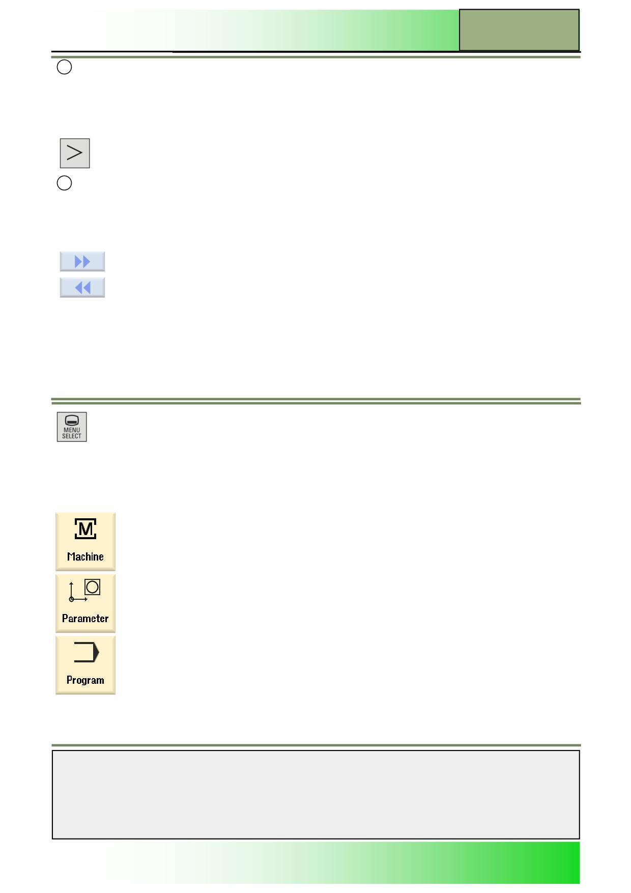
The user interface consists of different subsections. At the bottom of the screen is the horizontal softkey bar (HSK) con-
taining 8 softkeys (see Section 2.2.1 in this module). The selection of a new window is made by pressing the buttons just
under the softkeys. If the number of functions exceeds the representation capacities of the maximum of 8 softkeys than a
partitioning in two different horizontal softkey bars occurs.
The change over forth and back takes place with the “Menu extend“-key
on the operator panel.
12
Vertical softkey bar (VSK)
The available functions and operating modes can be selected from the keys right beside the vertical softkey bar (VSK) on
the right hand side of the screen. If the number of functions exceeds the representation possibility capacity of the maxi-
mum of 8 softkeys than a partitioning in two different vertical softkey bars occurs.
The changeover takes place with the:
“Forward“-key or the
“Backward“-key (VSK 8).
Operating with softkeys and buttons
The Sinumerik Operate separates into 6 different operating areas (“Machine“, “Parameter“, “Program“, “Program Manag-
er“, “Diagnostics“, “Start-up”), 3 operating modes (“JOG”, “MDA”, “AUTO”) and 2 functions (“REPOS”, “REFPOINT”).
By pressing the button “MENU SELECT“ on the operator panel the active
screen will be overlaid with the display of a yellow horizontal softkey bar at
the bottom and a yellow vertical softkey bar on the left side of the screen.
They consist of 6 operating area softkeys in the HSK and 3 operating
mode-, as well as 2 function softkeys in the vertical softkey bar.
Horizontal softkey bar (HSK)
Display area
Description
By pressing HSK 1 “Machine“ the operating are “Machine“ will be called up.
By pressing the HSK 2 “Parameter“ the operating area “Parameter“ will be called up.
By pressing the HSK 3 “Program“ the operating area “Program“ will be called up.
Notes
828D/840Dsl SINUMERIK Operate
Page 7
M568
M568
Basics of operation
By pressing the HSK 4 “Program Manager“ the operating area “Program Manager“ will be
called up.
By pressing the HSK 5 “Diagnose“ the operating area “Diagnose“ will be called up.
By pressing the HSK 6 “Setup“ the operating area “Setup“ will be called up.
Vertikale Softkey-bar (VSK)
Display area
Description
By pressing the VSK 1 “AUTO“ the operating mode “AUTO“ will be called up
By pressing the VSK 2 “MDA“ the operating mode “MDA“ will be called up.
By pressing the VSK 3 the operating mode “JOG“ will be called up.
By pressing the VSK 4 „REPOS“ the function „REPOS“ will be called up.
By pressing the VSK 5 „REF POINT“ the function “REF POINT“ will be called up.
Considerations for the input masks
Measurement units [metric/imperial]
The measurement units of all parameters used in the entire documentation are defined in the metrical system (mm). The
following table compares the equivalent imperial measuring units (inch and foot) with the metric system.
Note:
A description how to change between metric (mm) and imperial system (inch) can be found in the module B570 “Operating
mode JOG“.
Metric
Inch/foot
mm
in
mm/tooth
in/tooth
mm/min
in/min
mm/rev
in/rev
m/min
ft/min
Notes
M568
Page 8
828D/840Dsl SINUMERIK Operate
Basics of operation
M568
Parameter selection
The following described selection of parameters in an input mask can be called in every entry field where parameter
selection is possible and numerical input is not possible.
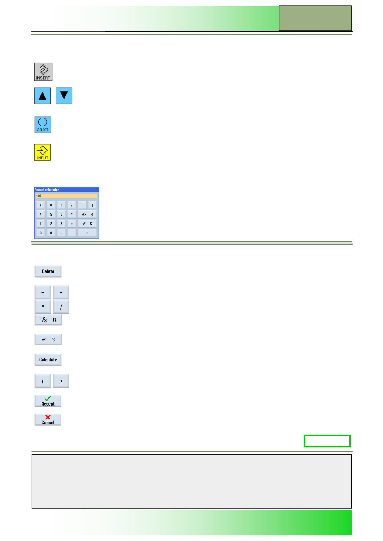
A list of possible parameters is displayed by pressing "INSERT" key on the keyboard
Navigation through the menu occurs with the blue cursor-keys.
Hint:
Navigation in long lists short cut can be used by pressing the initial letter or number of the
parameter directly on the keyboard. Each additional pressed letter continuous to restrict the
selection.
If the selected entry is orange highlighted (actual cursor position) then with pressing on of the
yellow “INPUT“ keys on the keyboard the chosen value is taken over into the input field.
Alternatively you can switch through a list of possible choices in the input field by pressing the
blue “SELECT“ key repeatedly.
Pocket calculator
The calculator can be called-up from every part of the operating area.
If a numerical entry is necessary in an input field you can open the pocket calculator by
pressing the equal sign (=) on the keyboard.
If their is already a value existing in the input filed e.g. 100 , then the value will be captured into
the calculator window.
Softkeys
Description
By pressing the softkey “Delete“ every input or outcome value in the calculator will be deleted.
For calculating values the four basic arithmetical operators are available,
as well as…..
square root (R) and….
Square (S).
If you enter the letter “R“ with a following number in the calculator and press the “Calculate“
button than the square root of the entry will be calculated. If you place first a “S“ instead of a
“R“ in front of the number, the square will be calculated.
A mathematical function with values in parenthesis allows the calculation of complex
mathematical expressions.
The softkey “Accept“ transfers the result to the input field and closes the pocket calculator
independently.
The button “Cancel“ closes the pocket calculator.
M568: END
Notes
828D/840Dsl SINUMERIK Operate
Page 9
M568

M568
Basics of operation
Notes
M568
Page 10
828D/840Dsl SINUMERIK Operate
M570
Operating mode “JOG“
Sinumerik
Operate
Module Description:
In this module the softkeys of the Sinumerik Operate, available in the manual mode (setup- and basic
functions), will be described.
Module Objective:
In this module you learn the different options of the operating area "Machine" in the oper-
ating mode "JOG".
Content:
Operating mode "JOG"
Tool, spindle and machine commands (T,S,M)
Set Work offset (“Set WO”)
Measure workpiece
Measuring a tool
Position
Face milling
Settings
This document was produced for training purposes.
828D/840Dsl SINUMERIK Operate v4.7
Page 1
M570
Siemens assumes no responsibility for its contents.
M570
M570
Page 2
828D/840Dsl SINUMERIK Operate

Operating mode “JOG“
M570
Operating mode
JOG:
START
Operating
mode "JOG"
Tool, spindle
and machine
commands
(T,S,M)
Set Work
offset
(“Set WO”)
Measure
workpiece
Measuring a
tool
Position
Face milling
Setting
Operating mode
JOG:
END
Notes
828D/840Dsl SINUMERIK Operate
Page 3
M570
M570
Operating mode “JOG“
Operating mode "JOG"
Operation mode “JOG” is used, for setting up the machine for program runoff or if you simply want to traverse the axes on
the machine:
Reference point approach, i.e. calibration of the position measuring system
Preparing a machine for executing a program in automatic mode, i.e. measuring tools, measuring the workpiece and, if
necessary, defining the work offsets used in the program
Traversing axes, e.g. during a program interruption
Positioning axes
Selecting the operating mode “JOG“
The operating mode "JOG" can be selected as follows:
Press the “JOG“ button on the machine control panel (MCP).
The operating mode “JOG” opens directly.
- OR -
Press the button “MENU SELECT“ on the machine control panel.
Press the VSK 1 “JOG“ in the yellow vertical softtkey bar on the right hand side of the screen to
switch directly to the operating mode “JOG“.
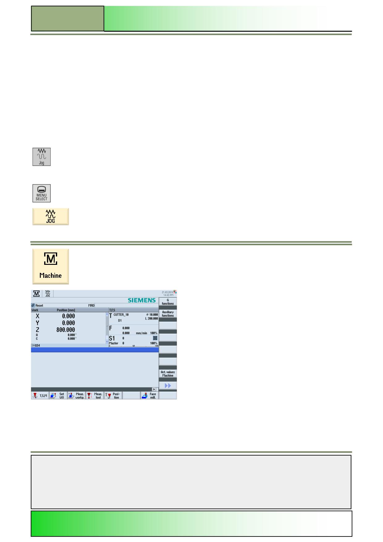
Then Switch to the operating area “Machine” by pressing the “MACHINE” key on the operator
panel or on the keyboard or press the “MENU SELECT“ key on the operator panel and the
yellow HSK 1 “Machine“.
The following screen opens:
The following functions are offered in the horizontal and vertical softkey bar of the operating area "Machine".
Notes
M570
Page 4
828D/840Dsl SINUMERIK Operate
Operating mode “JOG“
M570
Vertical softkey bars 1 and 2
Display area
Description
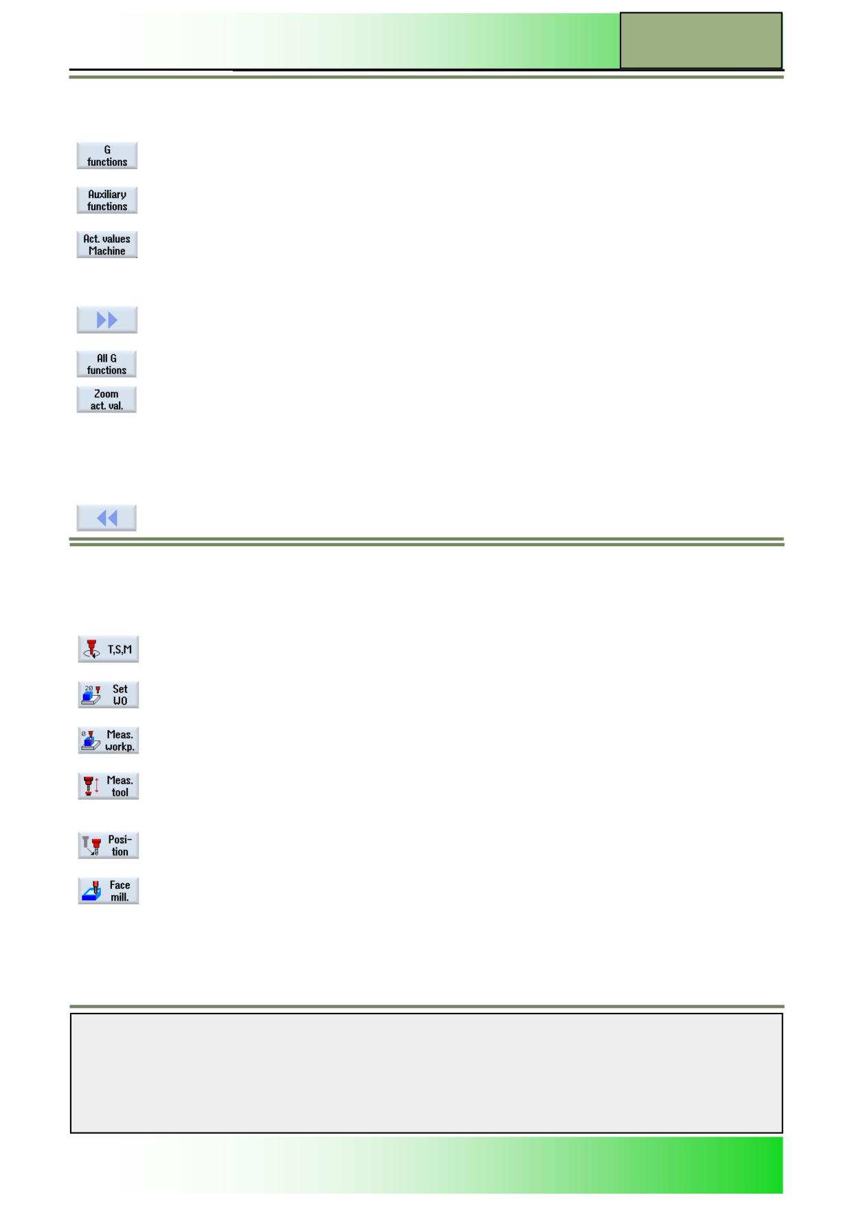
The most important G-functions are displayed in a sub-window by pressing the VSK 1.1 "G
functions".
Available auxiliary functions are displayed in a subwindow by pressing the VSK 1.2 "Auxiliary
functions" at the time of the output.
By pressing the VSK 1.7 "Act. values. Machine", the coordinate system will be toggled between
the machine coordinate system (MCS) and the workpiece coordinate system (WCS).
Note:
Refer to the machine manufacturer‘s documentation.
By pressing the VSK 1.8 "Forward" on the operator panel (OP) the selection of additional
softkeys on the vertical softkey bar is possible
By pressing the VSK 2.2 "All G functions" all G-functions will be shown.
By pressing the VSK 2.6 "Zoom act. val." all actual axes positions in the selected coordinate
system as well as the currently active feed rate and feed override of each individual axis are
displayed full screen. In addition all active zero point offsets, transformations and the T,F,S data
is being displayed in the foot line.
Note:
If the machine is in the sub-mode “REPOS”, then the in manual mode traversed path difference
is also being displayed.
By pressing the VSK 2.8 "Back" on the operator panel (OP) the vertical softkey bar switches
back to the menu of the VSK 1.
Horizontal softkey bar 1 and 2
Display area
Description
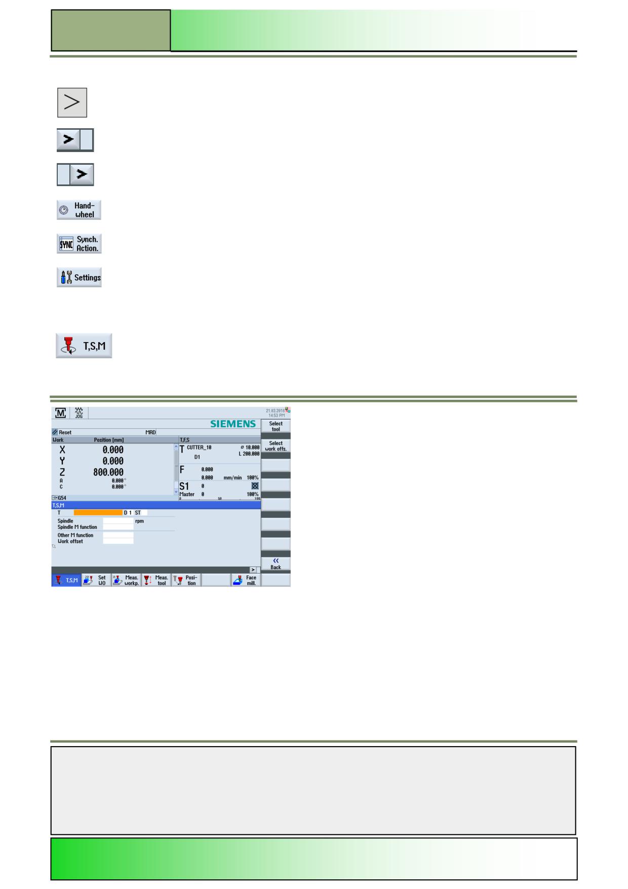
By pressing the HSK 1 "T,S,M" the input screen "T,S,M" will be activated.
By pressing the HSK 2 "Set WO" the input screen for setting the work offset will be activated.
By pressing the HSK 3 "Meas. workp.“ the input mask for measuring a workpiece will be activat-
ed.
By pressing the HSK 4 "Meas. tool" the function "Measure tool" will be activated and the ex-
tended options "Length/Radius manual", "Length/Radius auto", "Calibrate Probe", and
“Calibrate fixed pt.” will be available in the vertical softkey bar.
By pressing the HSK 5 "Position" the input screen "Target position" will be activated.
By pressing the HSK 7 "Face mill." the input screen "Face milling" will be activated.
Notes
828D/840Dsl SINUMERIK Operate
Page 5
M570
M570
Operating mode “JOG“
Display area
Description
By pressing the "Extend"-button on the operator panel (OP) more softkeys on the HSK are
available.
This symbol on the right of the dialogue line indicates that more options on the HSK are availa-
ble.
This symbol indicates that you are in the expanded softkey bar.
By pressing the HSK 2.6 "Handwheel" the input mask for traversing the axis in machine coordi-
nate system (MCS) or workpiece coordinate system (WCS) will be available.
By pressing the HSK 2.7 "Synch. Action." the screen which shows the current synchronized
actions is displayed.
By pressing the HSK 2.8 "Settings" a window opens up where you can adjust the settings for
manual operation on the Sinumerik Operate.
Tool, spindle and machine commands
Selecting the function "T,S,M"
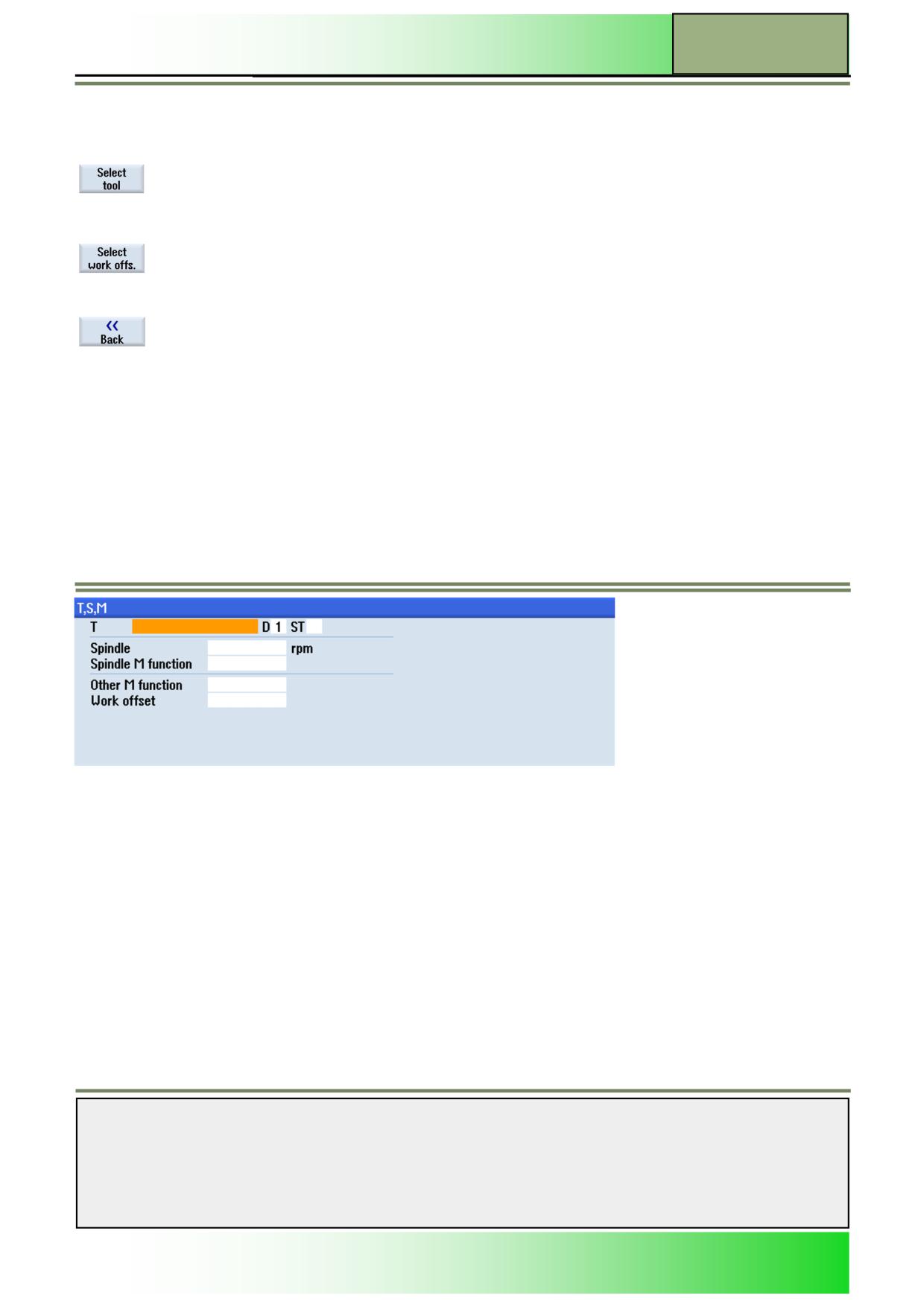
By pressing the HSK 1 "T,S,M" in operation area “Machine” under operation mode “JOG” the
following input mask will be displayed on the screen .
Notes
M570
Page 6
828D/840Dsl SINUMERIK Operate
Operating mode “JOG“
M570
Vertical softkey bar (VSK)
Display area
Description
By pressing the VSK 2 "Select tool" the tool list opens on the screen.
See module M573 - "Operating area Parameter".
By pressing the VSK 3 "Select work offs" a list with the zero point offsets will be displayed.
Refer to Work offset section 4 in this module
By pressing the VSK 8 "Back" switch back to the main screen of the Sinumerik Operate.
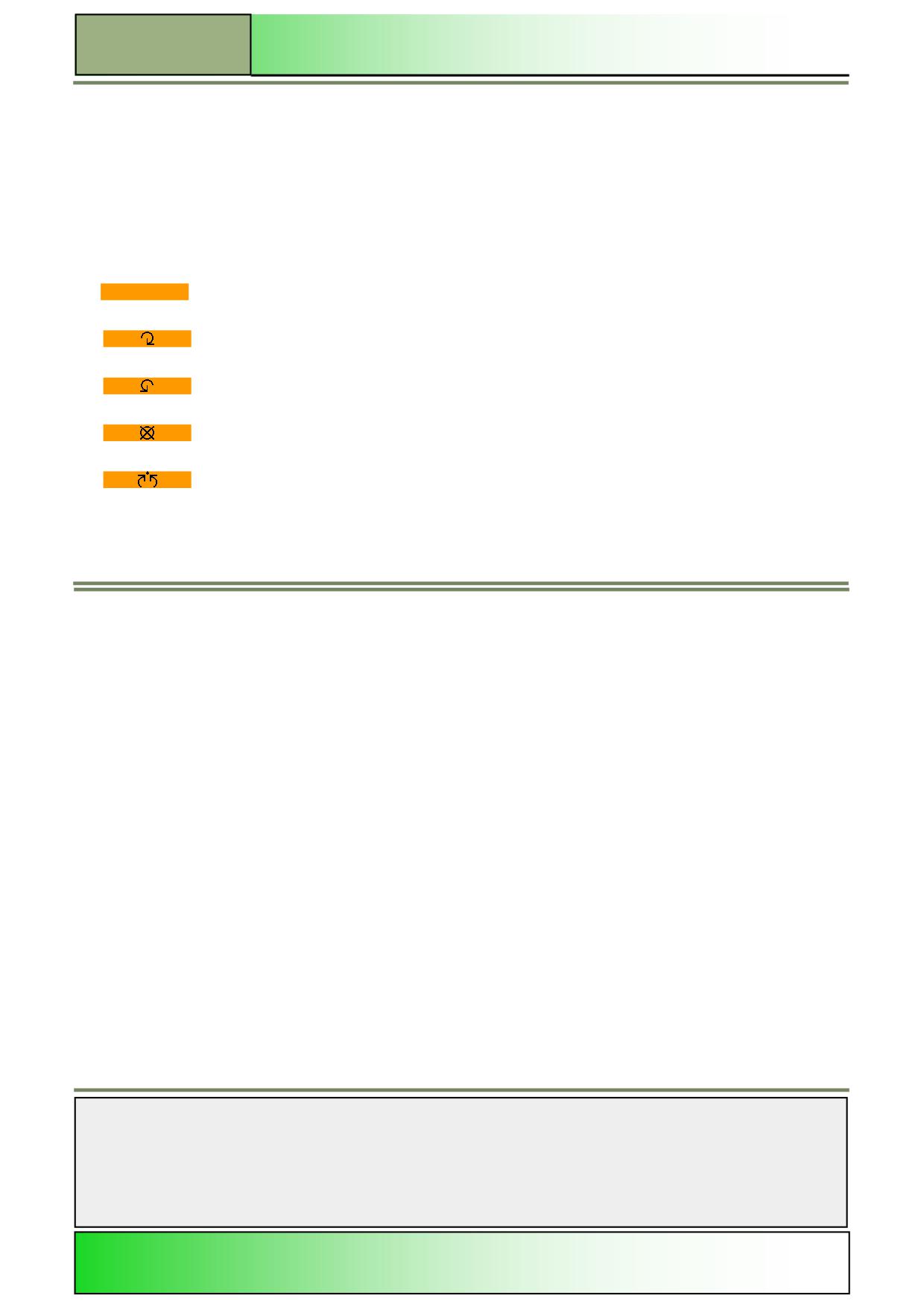
Parameters of "T,S,M" (Tool, spindle and machine commands)
Input mask for tool, spindle and machine commands:
Values can be entered directly in the orange marked input fields or by selecting predefined parameters with the “SELECT”
key. Alternatively the “INSERT” button in the marked cursor field opens a select menu of all possible parameters, in which
you can navigate with the “Tab” key as well as the blue “cursor-up” and “cursor-down” down buttons. The button “INPUT”
takes over the selected values. In order to be independently of country specific measuring units [metric/imperial] not all units
are displayed in the input masks.
See module M568 - "Basic operations".
In this documentation the measuring units are always metric.
Notes
828D/840Dsl SINUMERIK Operate
Page 7
M570
M570
Operating mode “JOG“
Parameter
Unit
Meaning
T
Tool name: e.g.: T12 or Cutter_7 (alphanumerical).
D
Cutting edge number of the tool.
Spindle:
[rpm]
Spindle speed (revolutions per minute, numerical).
Spindle M function:
Spindle machine functions: (Make a selection using the "SELECT" key
on the keyboard).
No selection is made.
Empty field
Clockwise rotation of the spindle.
Right(M 3)
Counter clockwise rotation of the spindle.
Left (M 4)
Spindle is stopped.
Off (M 5)
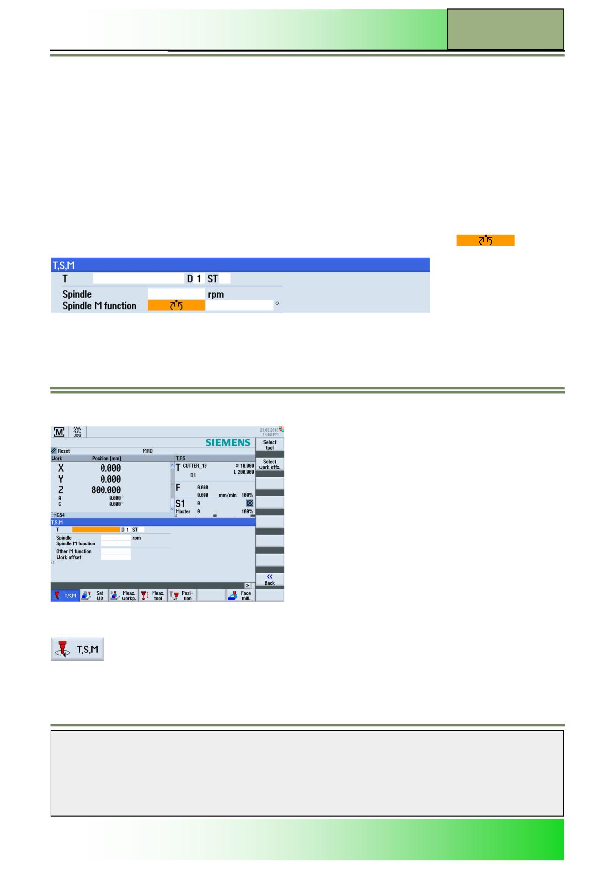
Spindle positioning: Spindle is positioned to the desired position.
Positioning (SPOS)
Other M function:
Manufacturer defined M-functions. By inserting the number of the
function, a corresponding M-function is selected.
Refer to the machine manufacturer‘s table for the correlation between
the meaning and the number of the function.
Parameter
Unit
Meaning (continuation)
Work offset:
Alternative parameter options:
The actual value of the work offset refers to the machine zero point, after
None
approaching the reference point.
In contrast a machining program refers to the workpiece zero point. This offset is to
Basic reference
be entered as zero point offset.
G54
You can select work offsets from the tool list of settable work offsets via the "Work
offset" softkey.
G55
See module M573 - "Operating area Parameter".
G56
G57
Unit of measure.:
Alternative parameter options:
none
[mm]
Note:
mm
[inch]
The setting made here has effect on the programming.
inch
Notes
M570
Page 8
828D/840Dsl SINUMERIK Operate
Operating mode “JOG“
M570
Parameter
Unit
Meaning (continuation)
Machining plane:
G17
(XY)
(ZX)
G18
(YZ)
G19
Gear stage:
Specification of the gear stage
(none, auto, I - V).
Stop-Position:
[Degree] Input of the spindle position in degrees.
Note:
This parameter shows up by selecting the spindle M-function
Note:
With “CYCLE START“ the inserted values will be executed. The entries in the option fields will be deleted, ready for new
inputs.
Tool definition and call with the input mask "T, S, M"
By pressing the HSK 1 "T, S, M" on the screen
See above in the working window open the "T, S, M" input box.
Notes
828D/840Dsl SINUMERIK Operate
Page 9
M570
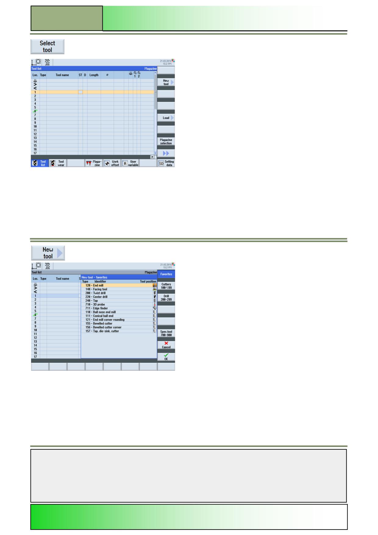
M570
Operating mode “JOG“
The VSK 1 "Select tool" Softkey appears. Pressing this soft key will open the tool list.
Press VSK 1 "New tool" Softkey to open the “Favorites” tool selection.
Notes
M570
Page 10
828D/840Dsl SINUMERIK Operate
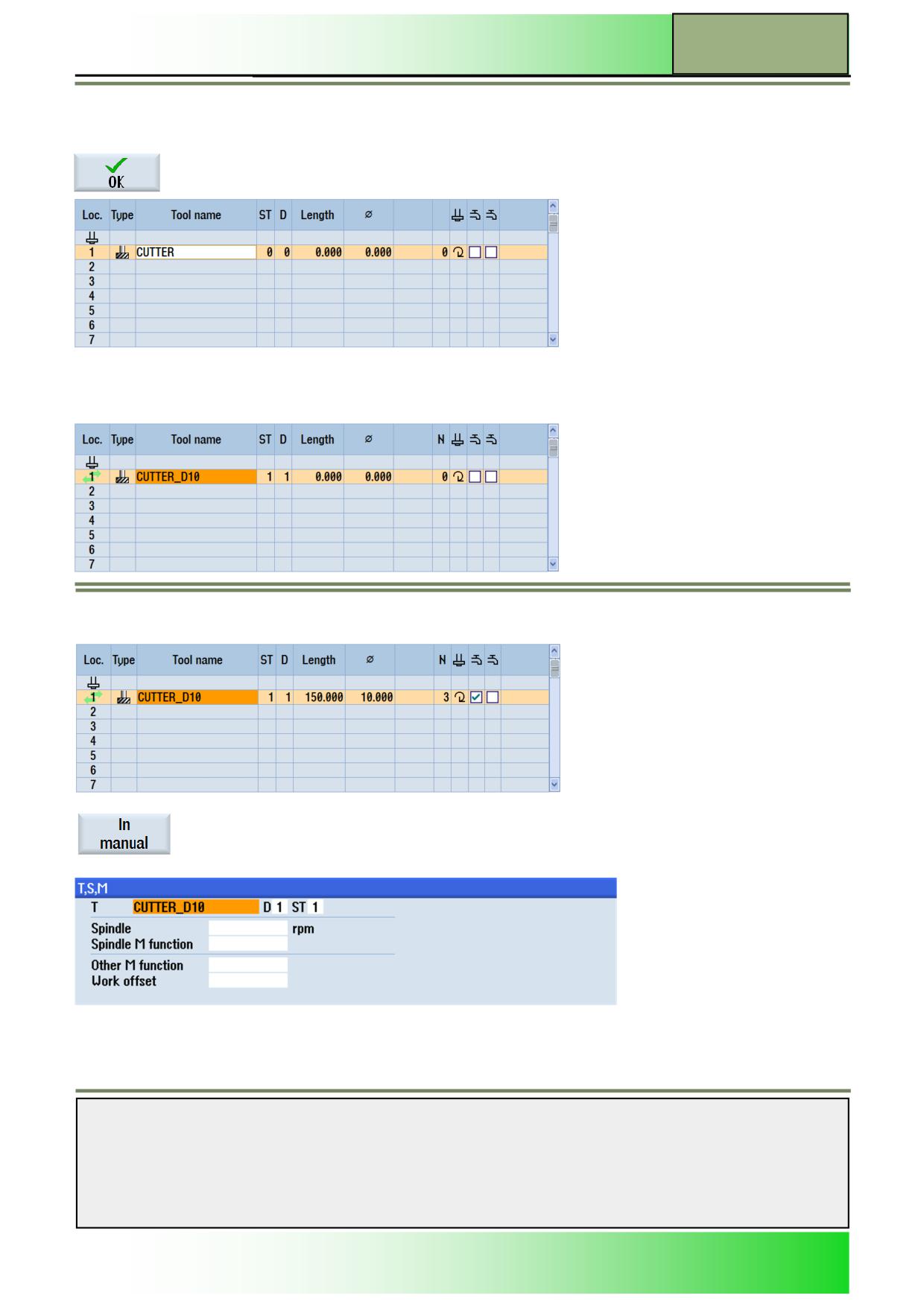
Operating mode “JOG“
M570
Opened by default, VSK 1 "Favorites" Softkey, you will find the most common tools. By pressing on the soft keys such as
"Drill", only drilling tools are offered. In our example, the first tool "Type 120 - End mill" is used.
With the VSK 8 "OK" Softkey, the selected tool is created in the “Tool list”.
The name of the tool can be modified if required.
For example, the tool name is edited from MILLING CUTTER with the
Insert and Delete keys and changed to CUTTER_D10.
Data should now be entered if known, the tool length, the correct tool radius or diameter, and number of edges, spindle
direction and possibly external coolant supply can be activated.
Press VSK 1 "In Manual", the tool name is now moved into the input window
of T, S, M.
Notes
828D/840Dsl SINUMERIK Operate
Page 11
M570
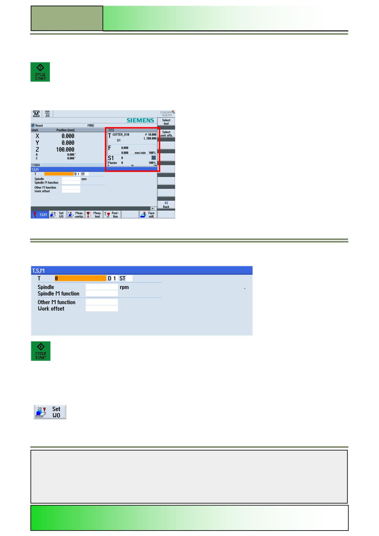
M570
Operating mode “JOG“
The tool could also have speed and direction data entered, if it is still stored in the magazine.
In this example CYCLE START is pressed to initiate the tool change.
CYCLE START triggers the tool change functions without additional commands such as M06.
The tool should now appear in the window technology (outlined in red), the tool from the tool list with details of length, radius
and edge number.
To return the tool in the spindle to the magazine must only be undertaken using "T, S, M"
In the input field T enter "0".
CYCLE START triggers the tool change functions without additional commands such as M06.
Work Offset
By pressing the HSK 2 "Set WO" in operation area “Machine” under operation mode
“JOG” the input field for the programming of a work offset will be opened, like dis-
played below.
Notes
M570
Page 12
828D/840Dsl SINUMERIK Operate