SINUMERIK 840D sl. Training. Operate - Turning (2016-2020) - page 12
Multi-channel machining
14
14.1
Overview
SINUMERIK 828D
SINUMERIK 828D
SINUMERIK 828D
BASIC
ADVANCED
not available
not available
Option: P05
SINUMERIK 840D sl
SINUMERIK 840D sl
BASIC
Option: M27
Option: M27
SINUMERIK Operate offers numerous functions to support you with programming and
production of multi-channel machining processes.
With programSYNC, you can easily synchronize, optimize and visualize programs for multi-
channel machining processes.
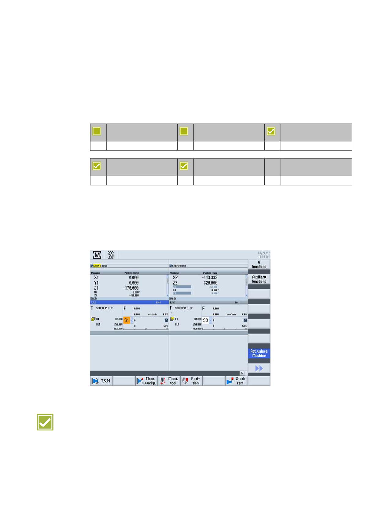
For the machine basic screen you can choose between single-channel and multi-channel
view. The active channel is highlighted in color.
Benefit
● SINUMERIK supports the easy handling of complex machines.
SINUMERIK Operate - Turning
Control system overview for machine tools' sales people, 2017, A5E41992653B AA
73
Multi-channel machining
14.2 programSYNC job list
14.2
programSYNC job list
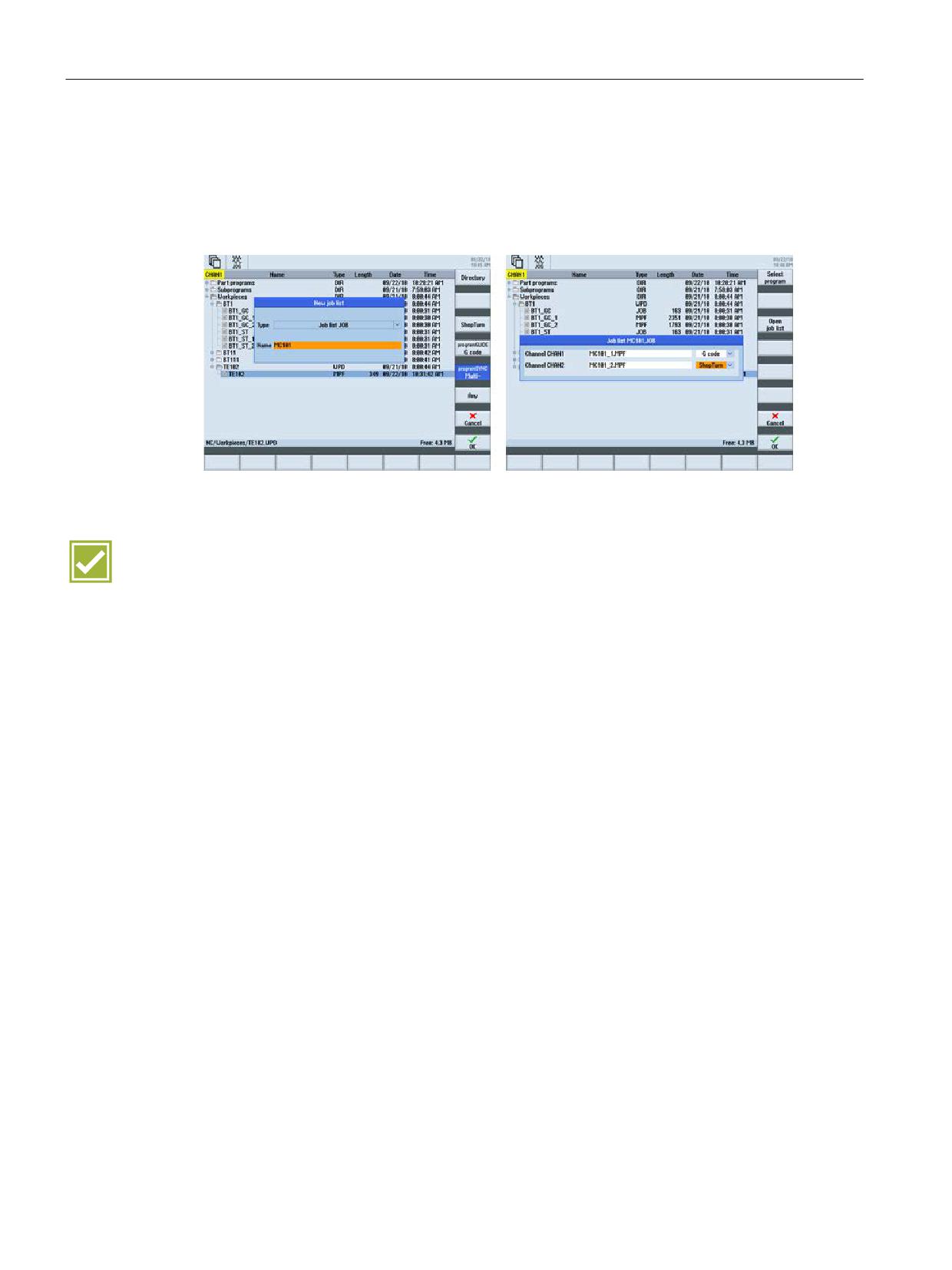
In programSYNC multi-channel, the programs for processing of the respective channels are
managed in job lists. In the job list, you assign arbitrary ShopTurn or G code programs to the
respective channels.
Benefit
● Simple program management in Windows Explorer style
SINUMERIK Operate - Turning
74
Control system overview for machine tools' sales people, 2017, A5E41992653B AA
Multi-channel machining
14.3 Double editor
14.3
Double editor
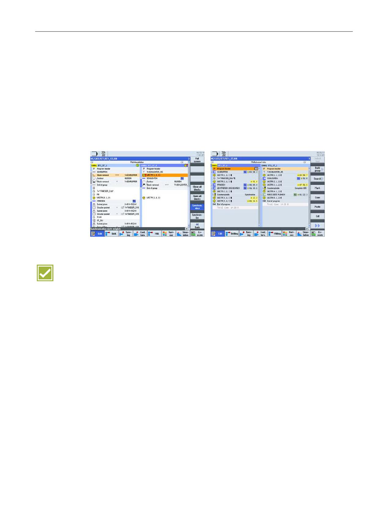
The double editor facilitates the creation of the programs for the respective channels.
● You structure the programs by means of blocks. These can be expanded and collapsed
for a clear representation.
● In the double editor, you can program the chronological sequence and check the wait
marks through the synchronized view.
● Through the automatic time evaluation, you can further optimize the multi-channel
program in the double editor. If required, you can transfer individual machining processes
to other channels to create a time-optimized program.
Benefit
● Easy creation of time-optimized programs through synchronization of wait marks and
determination of the processing time of the respective blocks
SINUMERIK Operate - Turning
Control system overview for machine tools' sales people, 2017, A5E41992653B AA
75
Multi-channel machining
14.4 Multi-channel stock removal cycle
14.4
Multi-channel stock removal cycle
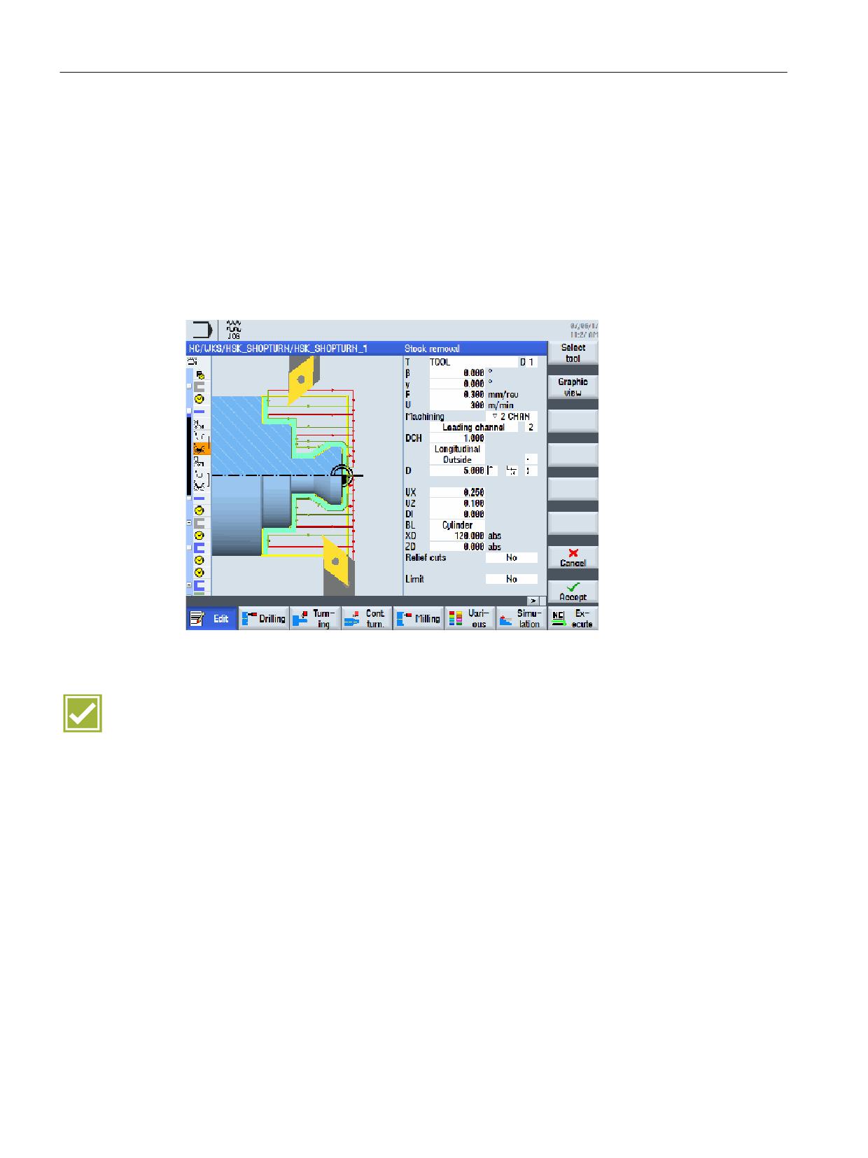
With the intelligent multi-channel stock removal cycle CYCLE952, contours can be machined
in a variety of ways. Powerful functions facilitate the workpiece machining:
● Automatic detection of residual material ensures an optimum cut segmentation
● Automatic feedrate interruption breaks the chips evenly and removes them
4-axis stock removal with CYCLE952 is available on multi-channel turning machines.
Benefit
● Cylce support enables efficient programming of complex machining tasks for multi-
channel turning machines
SINUMERIK Operate - Turning
76
Control system overview for machine tools' sales people, 2017, A5E41992653B AA
Multi-channel machining
14.5 Simulation
14.5
Simulation
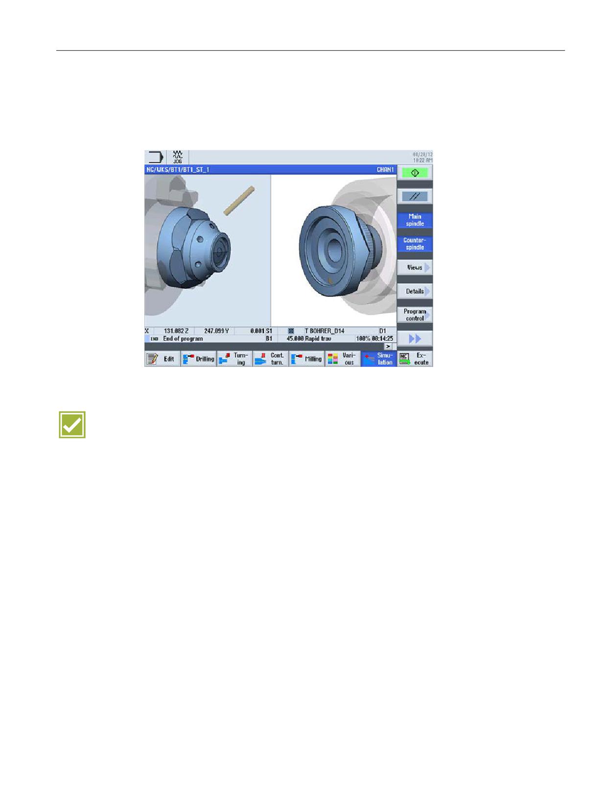
For the simulation, you can select, among other things, machining on the main spindle and
counterspindle and choose between different views, including 3D view.
Benefit
● With the workpiece simulation, SINUMERIK offers optimum help and safety for
programming - even during parallel machining
SINUMERIK Operate - Turning
Control system overview for machine tools' sales people, 2017, A5E41992653B AA
77
Multi-channel machining
14.5 Simulation
SINUMERIK Operate - Turning
78
Control system overview for machine tools' sales people, 2017, A5E41992653B AA

SINUMERIK Integrate Run MyRobot
15
15.1
SINUMERIK Integrate Run MyRobot / EasyConnect
SINUMERIK 828D
SINUMERIK 828D
SINUMERIK 828D
BASIC
ADVANCED
Basic configuration
Basic configuration
Basic configuration
SINUMERIK 840D sl
SINUMERIK 840D sl
BASIC
Basic configuration
Basic configuration
The prepared Run MyRobot / EasyConnect configuring interface permits the connection of
handling robots to machine tools.
● Prepared NC/PLC interface in accordance with VDMA/VDW 34180
● Prepared CNC diagnostic screen
Note:
The robot is normally connected to the CNC by the machine manufacturer or a system
integrator.
Benefit
● The prepared Run MyRobot / EasyConnect configuration interface provides a universal
and manufacturer-independent interface for the low-effort automation of machine tools.
SINUMERIK Operate - Turning
Control system overview for machine tools' sales people, 2017, A5E41992653B AA
79

SINUMERIK Integrate Run MyRobot
15.2 SINUMERIK Integrate Run MyRobot / Handling
15.2
SINUMERIK Integrate Run MyRobot / Handling
SINUMERIK 828D
SINUMERIK 828D
SINUMERIK 828D
BASIC
ADVANCED
not available
not available
not available
SINUMERIK 840D sl
SINUMERIK 840D sl
BASIC
Option: P74
Option: P74
The Run MyRobot / Handling option enables a robot to be operated, programmed and
diagnosed for handling tasks with SINUMERIK Operate.
● Operation, teaching and programming of the robot in the familiar CNC programming
environment.
● Minimum training effort, because fully integrated in SINUMERIK Operate.
● Efficient loading and unloading of a machine by direct programming in a control system.
Note
The robot is connected to the CNC by the machine tool manufacturer or a recommended*
system integrator.
* For details, please contact your local Siemens office.
Benefit
● Run MyRobot / Handling offers the integration of handling robots in machine tools with
the best-possible user-friendliness thanks to the familiar CNC look-and-feel.
SINUMERIK Operate - Turning
80
Control system overview for machine tools' sales people, 2017, A5E41992653B AA
Tools and information
16
16.1
DXF reader
SINUMERIK 828D
SINUMERIK 828D
SINUMERIK 828D
BASIC
ADVANCED
Option: P56
Option: P56
Option: P56
SINUMERIK 840D sl
SINUMERIK 840D sl
BASIC
Option: P56
Option: P56
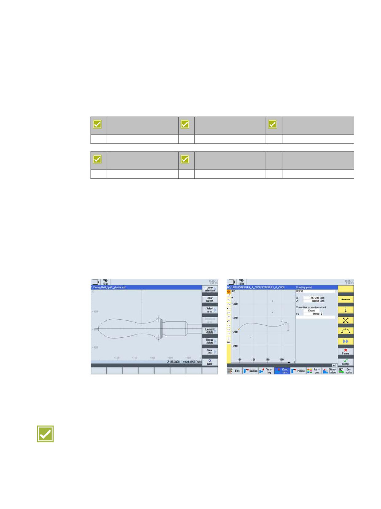
The integrated DXF Reader allows you to accept and extract contours and positions from
DXF files.
● DXF Reader in the Program Manager
With the Program Manager, you can open DXF files in the DXF Reader. You can either
clean DXF data automatically or select the desired layer yourself.
● Import DXF data in the contour calculator
You can either clean the imported DXF data automatically or select the desired layer
yourself.
Cleaned DXF data can be buffered as new DXF file.
● Import DXF data in position patterns
You can import the positions from a DXF file for position patterns for the associated
technologies.
Benefits
● Time saving for generating the production data
● Avoidance of mistakes and inaccuracies
● Higher workpiece quality
SINUMERIK Operate - Turning
Control system overview for machine tools' sales people, 2017, A5E41992653B AA
81

Tools and information
16.2 SinuTrain for SINUMERIK Operate
16.2
SinuTrain for SINUMERIK Operate
SINUMERIK 828D
SINUMERIK 828D
SINUMERIK 828D
BASIC
ADVANCED
Option: C43
Option: C43
Option: C43
SINUMERIK 840D sl
SINUMERIK 840D sl
BASIC
Option: C43
Option: C43
SinuTrain for SINUMERIK Operate is a PC-based CNC programming software package
based on the original CNC kernel. SinuTrain for SINUMERIK Operate enables identical
operation and CNC programming as for SINUMERIK CNCs that are equipped with the
SINUMERIK Operate graphical user interface.
SinuTrain for SINUMERIK Operate taps into the following applications:
In work preparation:
● Increased machine availability thanks to work preparation on the CNC programming
station and safety by offline verification of the programs
●
1:1 operation and programming as on the machine means no new operating or
programming knowledge is required
In training:
● Simple learning and professional training thanks to preconfigured machines and no
additional hardware costs
● Learning as on the CNC, with additional tutorials and programming guides
For presentation:
● Present always and everywhere
● Live demonstration of (new) SINUMERIK functions instead of slides
Note
The basic version of SinuTrain for SINUMERIK Operate is available as download in the
Internet. More information is available in the Internet at:
Benefits
● Controller-identical PC software for training and work preparation with configuration of the
real machine on the PC
● Preparation of the part program anywhere without needing a machine
● Prediction of the production time
SINUMERIK Operate - Turning
82
Control system overview for machine tools' sales people, 2017, A5E41992653B AA
Tools and information
16.3 CNC4you
16.3
CNC4you
On the CNC4you portal, SINUMERIK users can find helpful tips & tricks, SinuTrain
downloads, tutorials and more.
CNC4you portal:
SINUMERIK Operate - Turning
Control system overview for machine tools' sales people, 2017, A5E41992653B AA
83
Tools and information
16.3 CNC4you
SINUMERIK Operate - Turning
84
Control system overview for machine tools' sales people, 2017, A5E41992653B AA

Safety functions
17
17.1
SINUMERIK Safety Integrated
SINUMERIK 828D
SINUMERIK 828D
SINUMERIK 828D
BASIC
ADVANCED
Option: refer to the
Option: refer to the
Option: refer to the
catalog
catalog
catalog
SINUMERIK 840D sl
SINUMERIK 840D sl
BASIC
Option: refer to the
Option: refer to the
catalog
catalog
SINUMERIK Safety Integrated provides integrated safety functions that support the
implementation of highly effective personnel and machine protection. The safety functions
comply with the requirements of Category 3 as well as Performance Level d according to
DIN EN ISO 13849-1 and Safety Integrated Level SIL2 of IEC 61508.
As a consequence, the essential requirements concerning the functional safety can be
implemented simply and cost-effectively.
The functional safety for machine tools covers:
● Functions for the safe monitoring of speed and standstill
● Functions for establishing safe boundaries in work spaces and protected spaces, and for
range recognition
● Functions for the safe activation and testing of holding brakes
● Direct connection of all safety-related sensors/actuators and their internal logic
combination
Benefits
● High level of flexibility: Supports the implementation of practical safety and operating
concepts
● High level of security: Complete implementation of the safety functions in Category
3/SIL 2
● Increased availability: Absence of interference-susceptible electromechanical switching
elements
● High degree of cost effectiveness: Reduction of the hardware and installation costs;
simple commissioning and acceptance
SINUMERIK Operate - Turning
Control system overview for machine tools' sales people, 2017, A5E41992653B AA
85
Safety functions
17.2 Collision avoidance
17.2
Collision avoidance
SINUMERIK 828D
SINUMERIK 828D
SINUMERIK 828D
BASIC
ADVANCED
not available
not available
not available
SINUMERIK 840D sl
SINUMERIK 840D sl
BASIC
Option: S02
Option: S02
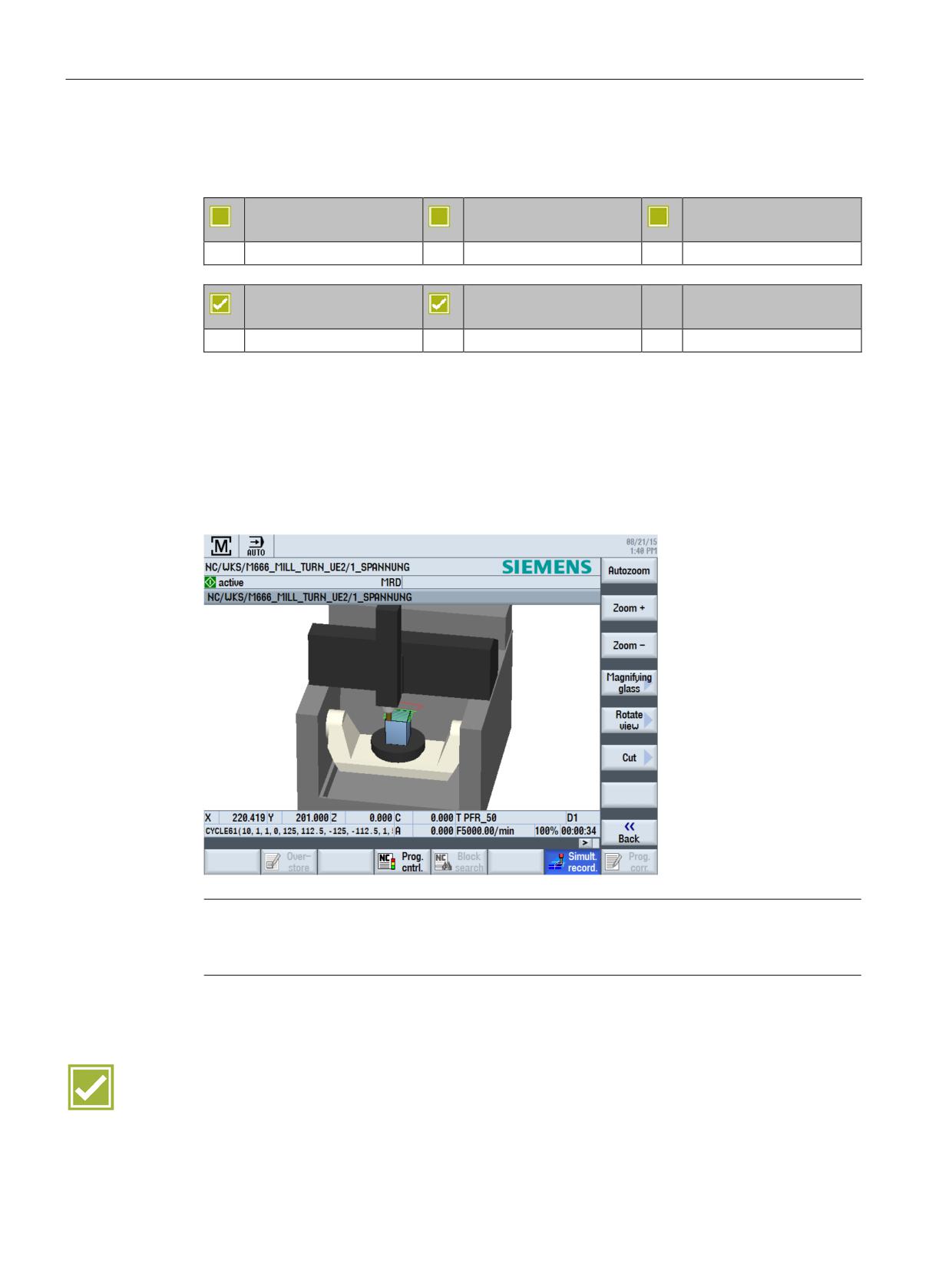
The SINUMERIK Collision Avoidance option provides optimum protection against
unintentional collisions of moving machine components with stationary machine
components.
You can active the collision monitoring in the Machine operating area for the JOG, MDA and
Automatic operating modes.
The Automatic operating mode provides for logging a 3D visualization of the collision
monitoring.
Note
The use of collision monitoring requires the availability of the relevant machine data and the
associated visualization.
Benefit
● Collision monitoring also possible for complex machining operations, such as 5-axis
simultaneous milling or turning with B axis
SINUMERIK Operate - Turning
86
Control system overview for machine tools' sales people, 2017, A5E41992653B AA
Summary of unique features
18
18.1
SINUMERIK 828D
The SINUMERIK 828D operator panel controller has the following notable features:
Compact
● Robust and maintenance-free design
● All relevant functions at a glance on the 10.4" color screen
● Full-function QWERTY CNC keyboard for user-friendly programming at the machine
● Full freedom of data transfer via USB, CF card and Ethernet, directly at the operator
panel
High
●
80-bit NANO floating-point accuracy for maximum precision of the workpiece results
● Free input of blank contours allows more efficient machining thanks to orientation on
actually available material
● Powerful transformations for end faces and envelope faces of turned workpieces and
oblique machining of milling workpieces
● Simple handling of tool and magazine data through clear and powerful tool management
Simple
● Animated Elements: unique facility to display machining parameters with animated
sequences
● ShopTurn machining step programming: shortest programming times and clear CNC
programs with technological sequences
● Common user interface for milling and turning
● Easy Message: simple process monitoring by SMS
SINUMERIK Operate - Turning
Control system overview for machine tools' sales people, 2017, A5E41992653B AA
87
Summary of unique features
18.2 SINUMERIK 840D sl
18.2
SINUMERIK 840D sl
The operator panel control SINUMERIK 840D sl with SINUMERIK Operate has the following
notable features:
Open
● Universal operator interface for milling, turning and additional technologies
● Simple handling of tool and magazine data through clear and powerful tool management
● Wide range of programming options using ShopTurn machining step programming,
programGUIDE and DIN/ISO programming
Flexible
● High performance cycles for automatic workpiece and tool measurement
● Full freedom of data transfer via USB, CF card and Ethernet, directly at the operator
panel
● Can be used for simple 2-axis turning up to 5-axis multi-channel and simultaneous
machining
High
● programSYNC for multi-channel programming permits the user-friendly creation and
optimization of the programs for the respective channels
● Free input of blank contours allows more efficient machining thanks to orientation on
actually available material
● Powerful transformations for end faces and envelope faces of turned workpieces and
inclined machining of turning-milling workpieces
SINUMERIK Operate - Turning
88
Control system overview for machine tools' sales people, 2017, A5E41992653B AA
© Siemens AG 2017
Glossary
Functions and terms
SINUMERIK 840D sl
1D/3D clearance control in position control cycle with free direction, Run MyCC /CLC-FD
Option; order code M65
Article No.: 6FC5800-0AM65-0YB0
Available as a supplement to the function SINUMERIK Integrate Run MyCC /CLC, the function SINUMERIK Integrate Run MyCC
/CLC-FD can be used to specify the spatial direction of the controlled motion with 3 simulated axes. It is then possible to program
the control direction independently of the tool orientation (laser beam orientation) specified by the 5-axis transformation.
1D/3D clearance control in position control cycle, Run MyCC /CLC
Option; order code M40
Article No.: 6FC5800-0AM40-0YB0
1D/3D clearance control in the position control cycle Run MyCC /CLC controls one machine axis (or 3 machine axes in conjunction
with 5-axis transformation) plus a maximum of one gantry axis and makeSiemens NC 62 · 2017s it possible to automatically maintain
the constant clearance between the head and the workpiece that is technologically required for the machining process. The clear-
ance information is read in via a high-speed analog input.
The most important application for this option is laser cutting of flat or spatially formed metal sheets or tubes. The function can also
be used with a force sensor in order to implement force control (friction welding).
Restricted functionality of export versions:
Clearance control can be applied to only one axis because 5-axis transformation is not available. The number of interpolating axes
is restricted to 4 without Run MyCC /CLC and to 3 with Run MyCC /CLC.
1D clearance control in the IPO cycle
1D clearance control in the IPO cycle can be used, for example, to evaluate sensor signals via a high-speed analog input. 1D clearance
control in the IPO cycle can also be used to compute a position offset $AA_OFF for an axis via a synchronized action.
2D representation of 3D protection areas/working areas
You can use protection areas to protect various elements at the machine, their components and the workpiece against incorrect
movements. The 3-dimensionally programmed protection areas are displayed in 2D. This display also applies to the programmed
working area limitations.
Working area limitation
Protection areas 2D/3D
3D simulation 1 (finished part)
Option; order code P25
Article No.: 6FC5800-0AP25-0YB0
The simulation can be extended to 3D representation by means of the 3D simulation 1 (finished part) option. This extension also
applies to the simultaneous recording.
Siemens NC 62 · 2017
1

© Siemens AG 2017
Glossary
Functions and terms
SINUMERIK 840D sl
Acceleration with jerk limitation
To achieve an optimum acceleration pattern with reduced wear on the machine's mechanical parts, you can select SOFT in the
part program to ensure a continuous, jerk-free acceleration profile. When you select acceleration with jerk limitation, the speed
characteristic over the path is generated as a bell-shaped curve.
Access MyMachine /Ethernet
Article No.: 6FC5864-4AP41-0YB0
SINUMERIK Integrate Access MyMachine /Ethernet enables worldwide, secure remote operation and monitoring of a machine tool
automated with SINUMERIK. Remote access is always established via a secure connection based on TLS (previously SSL) via the
Internet (worldwide). The technical implementation of access to the Internet depends on the local conditions at the machine. Access
to the Internet can be implemented in different ways.
Access MyMachine /P2P
Option; order code P30
Article No.: 6FC5800-0AP30-0YB0
The function SINUMERIK Integrate Access MyMachine /P2P permits remote access to the SINUMERIK HMI to quickly diagnose the
machine's condition. It supports data uploads and downloads, analog and ISDN telephone links as well as access via the Internet.
Access MyMachine /P2P increases machine availability as it can quickly go online. Furthermore, it enables users to prepare essential
service callouts more effectively.
Access protection
Protection
Type
PLC
User
level
DB10
DBB 56
bit...
1
Password
-
Machine manufacturer: Development
2
Password
-
Machine manufacturer: Commissioning engineer
3
Password
-
End user: Service
4
Red key switch
7
End user:
position 3
Programmer, machine setter
5
Green key switch
6
End user:
position 2
Qualified operator who does not program
6
Black key switch
5
End user:
position 1
Trained operator who does not program
7
Switch position 0
4
End user:
Semi-skilled operator
Access to programs, data and functions is protected in a user-oriented hierarchical system of 7 access levels.
• 3 password levels (protection levels 1 to 3) for machine manufacturers and end users, and
• 4 keyswitch positions (protection levels 4 to 7) for end users (keyswitch positions can also be evaluated via PLC)
SINUMERIK CNCs thus have a multistage concept for controlling access rights.
Protection level 1 has the highest access rights and protection level 7 the lowest. A higher protection level automatically includes all
protection levels below it.
Access rights for protection levels 1 to 3 are preprogrammed by Siemens (default setting). An entered password has priority over
a keyswitch position, and machine manufacturers or end users can change access rights for protection levels 4 through 7.
Subprograms can be completely protected against unauthorized reading and display.
Passwords should be regularly changed from an industrial security perspective.
Action log
The action log records all operator actions and pending alarms for diagnostics purposes.
Advanced Position Control APC
Option; order code M13
Article No.: 6FC5800-0AM13-0YB0
The natural frequency of the machine can have a detrimental effect on the maximum speed of the machine and the surface charac-
teristics. The Advanced Position Control APC function raises the kv factor, improves the surface and therefore increases productivity
without requiring any changes to the mechanical components.
2
Siemens NC 62 · 2017
© Siemens AG 2017
Glossary
Functions and terms
SINUMERIK 840D sl
Advanced Surface
Option; order code S07
Article No.: 6FC5800-0AS07-0YB0
The Advanced Surface function is used to optimize the motion control. Accurate contours and perfect surfaces can be achieved
even at high machining speeds. With optimized speed management, Advanced Surface delivers better workpiece surfaces with a
higher workpiece yield.
Alarms and messages
• Alarms and messages:
All messages and alarms are output separately on the operator panel in plain text with date and time as well as the appropriate
symbol for the delete criterion. All alarms are saved in an alarm log that can be configured according to size.
• Alarms and messages in the part program:
Messages can be programmed to provide the user with information about the current machining situation during program execu-
tion. Message texts may be up to 124 characters long, and are displayed in 2 lines (2 62 characters). The contents of variables
can also be displayed in message texts.
Example 1:
N10 G1 F2000 B=33.333
N15 MSG ("Rotary table position:" "$AA_IW[B]" "Degrees")
Display in message line following traversal of block N10
Rotary table position: 33.333 degrees
Example 2:
N20 MSG ("Check" "$AA_IW[X]" "X position!")
Display: Check ... X position!
In addition to programming messages, alarms can also be set in a CNC program. An alarm always goes hand in hand with a
response from the CNC according to the alarm category. The alarm text must be configured, alarm numbers 65000 to 67999 are
available. A description of the responses to the various alarms can be found in the Commissioning Manual.
Example 3:
N100 SETAL (65001) Effect:
Display interlocking CNC start
Deletion: with reset
• Alarms and messages from the PLC:
Machine-specific alarms and messages can be displayed directly from the PLC program in plain text. Messages comprise status
messages and error messages. In the case of status messages, the display is immediately deleted when the condition is no longer
active, error messages must be acknowledged. User-specific alarm numbers from 40000 to 89999 can be assigned to general,
channel-specific, axis-specific and spindle-specific user alarms and messages. The response of the CNC to alarms or messages
can be configured. The configured alarm and message texts are saved in application-specific text files.
• Specific evaluation of alarms:
A channel-specific signal can be used to decide whether other channels may continue to be used when an alarm is issued.
Analog value control
System variable $A_OUTA(n) enables values from up to 8 analog outputs to be directly entered in the part program. The value
specified by the NCK can be changed by the PLC before it is output to the hardware of a SIMATIC DP ET 200 analog module.
The hardware outputs are written in the interpolation cycle.
Analyze MyCondition
Article No.: 6FC5684-7AP41-0YB0
Article No.: 6FC5684-7BP41-0YB0
Article No.: 6FC5684-7CP41-0YB0
SINUMERIK Integrate Analyze MyCondition provides test cycles for testing synchronized axes and universal axes and for performing
circularity tests; it also offers functionality for continuous data acquisition during production. It also supports the reporting of key
parameters regarding the wear of mechatronic components.
A condition-oriented maintenance routine keeps production machines running longer and reduces downtimes and outages.
Animated elements
Using short film sequences, animated elements provide support by allowing the user to look ahead during operation and
programming, especially in processes where the motion sequence is the primary consideration.
Siemens NC 62 · 2017
3
© Siemens AG 2017
Glossary
Functions and terms
SINUMERIK 840D sl
Asynchronous subprograms ASUB
An asynchronous subprogram is a CNC program which can be started in response to an external event (e.g. a digital input) or from
the PLC. Inputs are allocated to subprograms and activated by programming SETINT.
If the relevant event occurs, the CNC block currently being processed is immediately interrupted. The CNC program can be con-
tinued later at the point of interruption. Multiple asynchronous subprograms must be assigned different priorities PRIO so that they
can be processed in a certain order. Asynchronous subprograms can be disabled and re-enabled in the CNC program
(DISABLE/ENABLE).
Interrupt routines with fast retraction from the contour
Auto Servo Tuning AST
Auto Servo Tuning AST automates the process of adapting parameters to the control equipment, which controls the axes of a CNC
machine. The parameters are adapted according to the frequency response measurement of the machine dynamics. One of the
benefits of Auto Servo Tuning AST is that it facilitates the measuring process.
The axis control loops are individually optimized according to the target parameters selected by the user for an adaptive strategy.
In a second step, the control loop parameter settings are adjusted for axes that are identified as being involved in an interpolation
path, with the result that the correct dynamic response is obtained for all axes. This adaptation ensures coordinated movement of all
the axes along the interpolation path.
Call Auto Servo Tuning from part program AST call
Auxiliary function output
Auxiliary function output informs the PLC when the part program wants the PLC to handle certain machine switching operations.
This is accomplished by transferring the appropriate auxiliary functions and their parameters to the PLC interface. The transferred
values and signals must be processed by the PLC user program.
The following functions can be transferred to the PLC:
• Tool selection T
• Tool offset D/DL
• Feedrate F/FA
• Spindle speed S
• H functions
• M functions
Auxiliary function output may be carried out either with velocity reduction and PLC acknowledgement up to the next block, or before
and during travel without velocity reduction and without block change delay. Following blocks are then traversed without a time-out.
Axes, coupled motion
When a defined leading axis moves, the coupled-motion axes (following axes) assigned to it travel the traverse paths derived from
the leading axis, taking into account a coupling factor (setpoint coupling). Together, the leading axis and the following axes form a
coupled-axis grouping.
Definition and activation of a coupled-axis grouping take place simultaneously with the modal instruction TRAILON. A coupled-axis
grouping can consist of any desired combinations of linear and rotary axes. A coupled-motion axis can be assigned up to 2 leading
axes (in different coupled-axis groupings). A simulated axis can also be defined as the leading axis, in which case the real axis
actually does the traveling, taking into account the coupling factor. Another application for coupled-motion axes is the use of
2 coupled-axis groupings to machine the 2 sides of a workpiece.
4
Siemens NC 62 · 2017
© Siemens AG 2017
Glossary
Functions and terms
SINUMERIK 840D sl
Axial coupling in the machine coordinate system MCS
The subfunction "Axis collision protection" is implemented by SINUMERIK Integrate Run MyCC /PROT.
The subfunction "Axial coupling in the machine coordinate system" is implemented by the generic couplings.
Axis collision protection, Run MyCC /PROT
Generic coupling
Axis/spindle
Option; order codes A01 ... A28
Article No.: 6FC5800-0AA00-0YB0
An additional interpolating axis/spindle can extend the number of axes/spindles in the basic configuration.
Functions:
• POS/SPOS/M3, M4, M5 (from CNC block)
• POSA/SPOSA (from CNC block, modally)
• FC18/POS/SPOS/M3, M4, M5 (PLC axes)
• PLC-VDI interface (M3, M4, M5 directly)
• OSCILL (asynchronous oscillation)
• OSCILL (synchronous oscillation)
• do POS/SPOS/M3, M4, M5 (synchronized actions)
• Couplings (TRAIL, LEAD, EG, CP, ...)
• Path/geometry/additional path axes/GEOAX()
• Spindles for thread cutting, tapping and thread cutting with compensating chuck
• Setpoint output and actual values are available
• Commissioning with SINUMERIK Operate
Positioning axis/auxiliary spindle
Simulation axis/spindle
Virtual axis
Internal/external drives
Axis collision protection, Run MyCC /PROT
Option; order code N06
Article No.: 6FC5800-0AN06-0YB0
SINUMERIK Integrate Run MyCC /PROT supports collision protection of up to 20 axis pairs that, for example, move along a common
guide rail and that could collide with each other. The axes concerned can also be active in different channels. The traversing
directions of the axes of an axis pair can differ. A maximum spacing can also be monitored.
Restricted functionality of export versions:
Not possible.
Siemens NC 62 · 2017
5
© Siemens AG 2017
Glossary
Functions and terms
SINUMERIK 840D sl
Axis container
On rotary indexing machines/multi-spindle machines, the axes holding the workpiece move from one machining unit to the next.
Since the machining units are handled through different NCU channels, the axes holding the workpiece must be dynamically
reassigned to the corresponding NCU channel if there is a change in station/position. Axis containers are used for this purpose.
Only one workpiece clamping axis/spindle is active on the local machining unit at a time. The axis container combines the possible
connections to all clamping axes/spindles, of which only one is active at a time for the machining unit.
The available axes that are defined in the axis container can be changed by shifting the entries in the axis container. Shifting can be
triggered by the part program or synchronized actions: Keyword AXCTSWE(CT1).
Channel
Number in the logic
Logic machine axis
axis name
machine axis image
image
X
1
AX2
1 local maschine axis 2
Y
2
AX3
2 local maschine axis 3
Z
6
S1
7
CT1_SL1 Axis Container 1, entry 1
Axis container 1
Axis container 1
NC1_AX1
NC1_AX5
NC2_AX2
NC1_AX1
NC2_AX1
AXCTSWE(CT1)
NC2_AX2
NC1 AX5
NC2 AX1
Example of an axis container:
Following rotation of the axis container through 1, the channel axis Z is assigned to axis AX5 on NCU 1 instead of axis AX1.
Axis data output via PROFIBUS, Run MyCC /ADAS
Option; order code N07
Article No.: 6FC5800-0AN07-0YB0
SINUMERIK Integrate Run MyCC /ADAS enables axis and spindle data to be output to a special PROFIBUS or PROFINET device
module. This function can be used, for example, for process or machine monitoring functions in real time outside the CNC.
The required axis and signal type are selected by transferring a selection command (length: 8 bytes) to the CNC. SINUMERIK
Integrate Run MyCC /ADAS in the NC kernel then sends up to 30 axis data items (of 4 bytes each) to the slave in each PROFIBUS
cycle.
The transfer cycle can be equal to the position controller cycle, or a multiple thereof. Consistent receipt of data from each cycle can
be guaranteed only when the slave is operating in isochronous mode (or with PROFINET IRT).
Axis limitation from the PLC
The preactivation of protection areas with specification of a position offset is programmed in the part program. You can put the
preactivated protection areas into effect in the PLC user program via the PLC interface. As a result, the relevant protection area is
activated, for example, before a tool probe is swiveled into position in the working area, to see whether the tool or a workpiece is in
the path of the swiveling part.
The PLC can put another axis limitation into effect by activating the 2nd software limit switch via a PLC interface signal. This reduction
of the working area may become necessary, for example, when a tailstock is swiveled into position.
The change is immediately effective, and the 1st software limit switch plus/minus is no longer valid.
Protection areas 2D/3D
Axis/spindle replacement
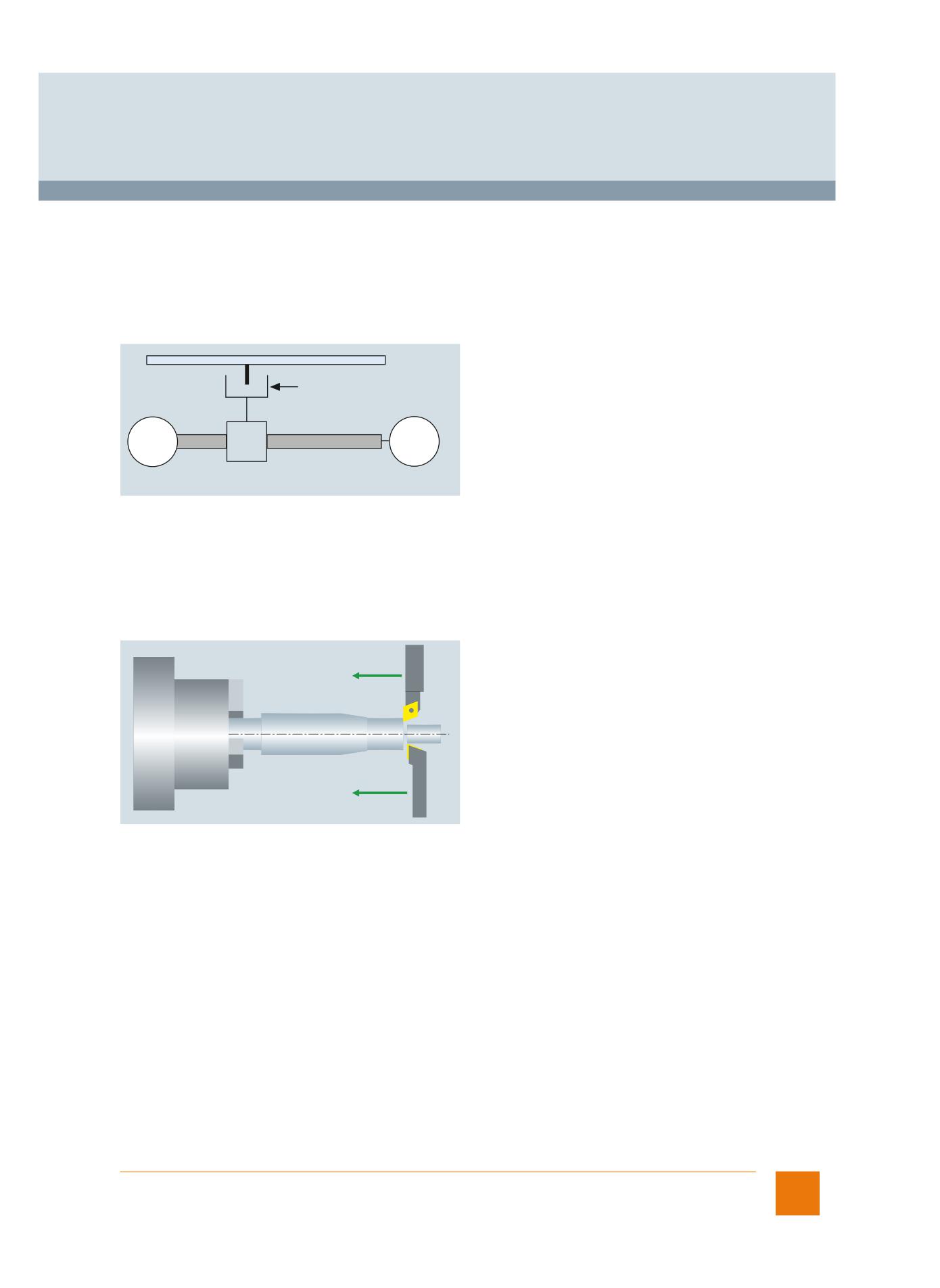
An axis/a spindle is permanently assigned to a specific channel via machine data. The axis/spindle replacement function can be
used to release an axis/a spindle (RELEASE) and to assign it to another channel (GET), i.e. to replace the axis/spindle. The relevant
axes/spindles are determined via machine data.
6
Siemens NC 62 · 2017
© Siemens AG 2017
Glossary
Functions and terms
SINUMERIK 840D sl
Backlash compensation
During power transmission between a moving machine part and its drive (e.g. ball screw), there is normally a small amount of back-
lash because setting mechanical parts so that they are completely free of backlash would result in too much machine wear. In the
case of axes/spindles with indirect measuring systems, mechanical backlash results in a corruption of the traversing path. For
example, when the direction of movement is reversed, an axis will travel too much or too little by the amount of the backlash.
To compensate for backlash, the axis-specific actual value is corrected by the amount of the backlash every time the axis/spindle
reverses its direction of movement. If a 2nd measuring system is available, the relevant backlash on reversal must be entered for
each of the two measuring systems.
Backlash compensation is always active in all modes following reference point approach.
Table
Backlash
Motor
Encoder
G_NC01_en_00098
Positive backlash (normal case)
The actual encoder value is ahead of the true actual value (table): The table does not travel far enough.
Balance cutting
Option; order code S05
Article No.: 6FC5800-0AS05-0YB0
The Balance cutting option (rough machining in 4 axes) permits faster machining of workpieces. Simultaneous machining on
opposite sides ensures balanced machining forces.
G_NC01_XX_00629
Bidirectional compensation
Leadscrew error compensation, bidirectional
Siemens NC 62 · 2017
7
© Siemens AG 2017
Glossary
Functions and terms
SINUMERIK 840D sl
Block search
The block search function allows any point in the part program to be selected where machining should start or be continued. The
function is provided for the purpose of testing part programs or to continue machining after it was canceled. Cascaded block search
is also possible.
Search variants:
• With calculation on the contour
During the block search, the same calculations are performed as in normal program operation. The target block is then traversed
true-to-contour until the end position is reached. Using this function it is possible to approach the contour again from any situation.
• With calculation at block end point
This function allows a target position to be approached (such as tool change position). All calculations are also executed here as
during normal program operation. The end point of the target block or the next programmed position is approached based on the
interpolation valid in the target block.
• Without calculation
This method enables high-speed searches in the main program. No calculations are carried out during the search. The internal
control values remain the same as before the block search.
• External block search without calculation
In the menus "Search position" and "Search pointer", the softkey "External without calculation" can be used to start an accelerated
block search for programs which are executed from an external device (local hard disk or network drive).
• Specify the search target by:
- Directly positioning the cursor on the target block
- Specifying a block number, a jump label, any character string, a program name, or a line number
8
Siemens NC 62 · 2017
© Siemens AG 2017
Glossary
Functions and terms
SINUMERIK 840D sl
Call Auto Servo Tuning from part program AST call
Option; order code S10
Article No.: 6FC5800-0AS10-0YB0
AST call allows machines to be optimized again automatically from the part program. The AST call function is thus particularly useful
for processes involving a wide range of different workpiece weights and clamping operations, and for machines driven by linear/
torque motors.
Auto Servo Tuning AST
Cartesian PTP travel
For handling and robot-related tasks, 2 types of movement are required: either in the Cartesian coordinate system Continuous
Path CP, or as a Point-to-Point PTP motion. With PTP, the shortest way to reach the end point is with activated TRAORI transformation.
PTP generates a linear interpolation in the axis space of the machine axis.
By smoothing from PTP to CP movement, it is possible to switch from fast infeed to a mounting or positioning movement with optimum
timing. PTP travel does not result in an axis overload when traveling through a singularity, such as changing an arm position during
handling. PTP travel is also possible in the JOG CNC operating mode and does not require Cartesian positions (e.g. from CAD
systems) to be converted into machine axis values.
Cartesian PTP travel is also used for cylindrical grinding machines with an inclined axis: With active transformation, the infeed axis
can be moved either according to Cartesian coordinates or at the angle of the inclined axis.
Cartesian travel to fixed stop, Run MyCC /FXSC
Option; order code N38
Article No.: 6FC5800-0AN38-0YB0
SINUMERIK Integrate Run MyCC /FXSC cartesian travel to fixed stop is used as a substitute for the standard travel to fixed stop
function for machine kinematics with OEM transformation. With this function, tailstocks or sleeves, for example, can be traversed to
a fixed stop in order to clamp workpieces. The clamping torque and a fixed stop monitoring window can be programmed in the part
program and set in the machine data. The function regulates the force to an adjustable value in the approach direction. In this case,
it can be utilized simultaneously in several channels.
Restricted functionality of export versions:
Not possible.
CCG compiler non-circular grinding (cam contour grinding)
Option; order code P10
Article No.: 6FC5800-0AP10-0YB0
Requirements: TRANSMIT option, order code M27 and polynomial interpolation option, order code M18.
This option is required for SINUMERIK 840D sl to allow the execution of part programs that have been generated with the CCG com-
piler tool. The OEM can either integrate the corresponding tool into the user interface on the PCU 50 or use it on an external PC.
The latest version of the tool is made available once on request, the option (runtime) must be ordered for each CNC. The CCG
compiler generates CNC programs in the polynomial format to allow the machining of non-circular contours on a cylindrical grinding
machine. The lift curves commonly used today, which describe the desired final contour in polar coordinates, are used as the input
data for programming and generating a complete CNC program.
The technology data, i.e. the number of infeed revolutions, allowance, sparking-out revolutions, angle of infeed and velocities, are
parameterized and taken into account when the part program is generated. The generated contour is not dependent on the tool
(grinding wheel) radius, because radius compensation (G41/G42) is active in the CNC.
Circle via center point and end point
Circular interpolation causes the tool to move along a circular path in a clockwise or counter-clockwise direction.
The required circle is described by:
• Starting point of circular path (actual position in the block before the circle)
• Direction of rotation of circle
• Circle end position (target defined in circular block)
• Circle center
The circle center can be programmed as an absolute value with reference to the current zero point or as an incremental value
with reference to the starting point of the circular path. If the opening angle is apparent from the drawing, then it can be directly
programmed. In many cases, the dimensions from a drawing are taken so that it is more convenient to program the radius in order
to define the circular path. In the case of a circular arc of more than 180 degrees, the radius specification is given a negative sign.
Siemens NC 62 · 2017
9
© Siemens AG 2017
Glossary
Functions and terms
SINUMERIK 840D sl
Circle via intermediate point and end point
If a circle is to be programmed, which does not lie in a paraxial plane but obliquely in space, an intermediate point can be used to
program it instead of the circle center. Three points are required to program the circle: the starting point, the intermediate point and
the end point.
Clamping monitoring
Clamping monitoring is one of the many extensive axis monitoring mechanisms implemented in SINUMERIK CNCs. When an axis is
to be clamped on completion of the positioning action, you can activate clamping monitoring using the PLC interface signal clamping
in progress. This may become necessary because it is possible for the axis to be pushed beyond the standstill tolerance from the
position setpoint during the clamping procedure.
The amount of deviation from the position setpoint is set via the machine data. During the clamping procedure, clamping monitoring
replaces standstill monitoring, and is effective for linear axes, rotary axes, and position-controlled spindles. Clamping monitoring is
not active in follow-up mode. When the monitoring function responds, its reactions are the same as those of the standstill monitoring.
Position monitoring
Standstill monitoring
CNC high-level language
To meet the various technological demands of modern machine tools, a CNC high-level language has been implemented in
SINUMERIK CNCs that provides a high degree of programming freedom.
System variables
The system variables ($.) can be processed in the CNC program (read, partially write). System variables allow access to, for
example, machine data, setting data, tool management data, programmed values, and current values.
User variables
If a program is to be used flexibly, variables and parameters are used instead of constant values. SINUMERIK CNCs give you the
option of executing all CNC functions and addresses as variables. The names of the variables can be freely defined by the user.
Read and write access protection can also be assigned using attributes. This means that part programs can be written in a clear
and neutral fashion and then adapted to the machine as required, for example, free selection of axis and spindle address designa-
tions.
User variables are either global GUD or local LUD. LUD can also be redefined via machine data to make them into global program
user variables (PUD). They are displayed in the Parameters operating area under the user data softkey, where they can also be
changed. Global user variables GUD are CNC variables that are set up by the machine manufacturer. They apply in all programs.
Local user variables LUD are available to the user for parameterizing CNC programs. These data can be redefined in every CNC
program. These variables make programming more user-friendly and allow the users to integrate their own programming philosophy.
Indirect programming
Another option for the universal use of a program is indirect programming. Here, the addresses of axes, spindles, R parameters, etc.,
are not programmed directly, but are addressed via a variable in which their required address is then entered.
Program jumps
The inclusion of program jumps allows extremely flexible control of the machining process. Conditional and unconditional jumps are
available as well as program branches that depend on a current value. Labels that are written at the beginning of the block are used
as jump destinations. The jump destination can be before or after the exit jump block.
Program coordination in several channels
Program coordination makes it possible to control the time-related execution in parallel operation of several CNC channels using
plain text instructions in the part program. Programs can be loaded, started and stopped in several channels. Channels can be
synchronized.
Arithmetic and trigonometric functions
Extensive arithmetic functions can be implemented with user variables and arithmetic variables.
In addition to the 4 basic arithmetic operations, there are also:
• Sine, cosine, tangent
• Arc sine, arc cosine, arc tangent
• 2. Power of 2 (squaring), square root
• Absolute value
• Integer component, round to integer
• Exponential function, natural logarithm
• Offset, rotation, mirroring
• Scale modification
10
Siemens NC 62 · 2017
© Siemens AG 2017
Glossary
Functions and terms
SINUMERIK 840D sl
Comparison operations and logic combinations
Comparison operations with variables can be used to formulate jump conditions.
The comparison functions that can be used are:
• Equal to, not equal to
• Greater than, less than
• Greater than or equal to
• Less than or equal to
• Concatenation of strings
The following logic combinations are also available: AND, OR, NOT, EXOR (EXclusive OR). These logic operations can also be
performed bit by bit.
Macro techniques
Using macros, single instructions from a programming language can be grouped together to form a complex instruction. This
shortened instruction sequence is given a freely definable name and can be called in the CNC program.
The macro command is executed in the same way as the single instructions.
Control structures
The CNC normally processes the CNC blocks in the order in which they are programmed. Control structures allow the programmer
to define additional alternatives and program loops as well as program jumps.
The commands make structured programming possible, and make the programs much easier to read:
• Choice of 2 alternatives IF-ELSE - ENDIF
• Continuous loop control LOOP
• Counting loop FOR
• Program loop with start condition WHILE
• Program loop with end condition REPEAT
CNC operating modes
3 CNC operating modes can be selected in the Machine operating area:
• JOG
JOG CNC operating mode (jogging) is intended for the manual movement of axes and spindles, as well as for setting up the
machine. The set-up functions are reference point approach, repositioning, traveling with the handwheel or in the predefined
incremental mode, and redefinition of the CNC zero point (preset/set actual value).
• MDI
In MDI (Manual Data Input) CNC operating mode, it is possible to enter individual program blocks or sequences of blocks for
immediate execution via CNC Start. These blocks can then be saved in part programs. With the Teach In function, motion
sequences are transferred to a program by returning and storing positions. The Teach In function can be used in the MDI CNC
operating mode.
• AUTO
In AUTO (automatic) CNC operating mode, the part programs are executed fully automatically once they have been selected in
the workpiece, part program or subprogram directory (normal operation). During AUTO mode it is possible to generate and correct
another part program.
In the MDI and AUTO CNC operating modes, the sequence of a program can be modified using the following program control
functions:
• SKP Skip block (up to 8 skip levels)
• DRY Dry run feedrate
• ROV Rapid traverse override
• SBL1 Single block with stop after sets of machine functions
• SBL2 Single block with stop after every block
• SBL3 Stop in cycle
• M01 Programmed stop
• DRF Differential resolver function
• PRT Program test
Siemens NC 62 · 2017
11
© Siemens AG 2017
Glossary
Functions and terms
SINUMERIK 840D sl
CNC program messages
All messages programmed in the part program and all alarms recognized by the system are displayed on the operator panel in plain
text. Alarms and messages are displayed separately. Messages can be programmed to provide the user with information about the
current machining situation during program execution.
Alarms and messages
CNC program transfer
Manage MyPrograms
CNC user memory
All programs and data, such as part programs, subprograms, comments, tool offsets, and zero offsets/frames, as well as channel
and program user data, can be stored in the shared CNC user memory. The CNC user memory is buffered with a battery.
CNC user memory, additional
Option; order codes D01 ... D06
Article No.: 6FC5800-0AD00-0YB0
The CNC user memory on the NCU can be expanded by 2 MB in each case using this option.
HMI user memory, additional on CF card of NCU
CNC user memory, expanded
Option; order code P77
Article No.: 6FC5800-0AP77-0YB0
The function "CNC user memory expanded" increases the CNC user memory to 100 MB. With option P12
"HMI user memory, in addition on CF card of NCU", it is possible to increase the size of the CNC user memory up to 6 GB. With a
PCU 50 it is possible to increase the size of the CNC user memory up to 40 GB.
HMI user memory, additional on CF card of NCU
COA interface for compiled OEM cycles, Run MyCCI /COOC
Option; order code M67
Article No.: 6FC5800-0AM67-0YB0
SINUMERIK Integrate Create MyCCI /COOC is an interface for the OEM's own developments relating to the CNC interpreter. Special
calculations that are too complex to implement in the CNC language (e.g. intensive matrix algebra) can be programmed in C++ with
a mathematics library to be provided by the user. CNC commands cannot be executed at C++ level.
The development of customized compile cycles in the interpreter is dependent upon a COA agreement and one-off purchase of the
option SINUMERIK Integrate Create MyCCI /INT.
Collision avoidance
Collision avoidance in real time
Collision avoidance in real time
Option; order code S02
Article No.: 6FC5800-0AS02-0YB0
The SINUMERIK collision avoidance option provides reliable protection against undesirable collisions between moving and non-
moving machine components in the machine's working area. The protection is effective in all operating situations.
SINUMERIK collision avoidance is focused on critical situations encountered in practice, e.g. during machine setup or machining
interruptions - in other words, when the operator intervenes in the process.
• 3D collision detection in real time
• Monitoring non-moving and moving machine components
• Efficient modeling of collision objects in SINUMERIK Operate on the PC with NX SINUMERIK Collision Avoidance
Requirements:
• SINUMERIK CNC software version 4.5 SP2 and higher
• 1-channel machine with one NCU
• SINUMERIK NCU 720.3B PN or NCU 730.3B PN (recommended)
• Simultaneous recording
• 3D simulation 1 (finished part)
12
Siemens NC 62 · 2017
© Siemens AG 2017
Glossary
Functions and terms
SINUMERIK 840D sl
Communication interface to a KUKA robot, Run MyCC /RODI
Option; order code N65
Article No.: 6FC5800-0AN65-0YB0
SINUMERIK Integrate Run MyCC /RODI is the communication interface to a KUKA robot that is operated using interpolation in the
SINUMERIK.
Machining with robot, Run MyRobot /Machining
Restricted functionality of export versions:
Not possible.
Compensation of a forced mechanical coupling in the machine coordinate system, Run MyCC /AXCO
Option; order code M81
Article No.: 6FC5800-0AM81-0YB0
SINUMERIK Integrate Run MyCC /AXCO allows movement of an axis that occurs due to mechanical coupling of an axis to a following
axis, to be compensated such that the axis remains mechanically stationary despite the coupling. The motor of the coupled axis is
rotated according to the set coupling ratio.
Restricted functionality of export versions:
Not possible.
Compile cycles interface, Run MyCCI /xy
SINUMERIK Integrate Run MyCCI /xy are loadable compile cycles and offer special interfaces for customized developments. This
software (interface) is produced with versions of the development tools which are identical to those used for the NCK basic software
of the SINUMERIK 840D sl.
For this special application, the customer uses software (GNU compiler/linker) in a Cygwin software shell on a Windows PC. This
concept of loadable interfaces therefore allows the OEM to develop real-time applications in C/C++ and to load them as customized
compile cycles.
Develop compile cycles, Create MyCC
Integrated tool monitoring and diagnostics IMD BASE, Run MyCC /IMD
Universal spatial compensation interface, Run MyCCI /UCI
COA interface for compiled OEM cycles, Run MyCCI /COOC
Concatenated transformations
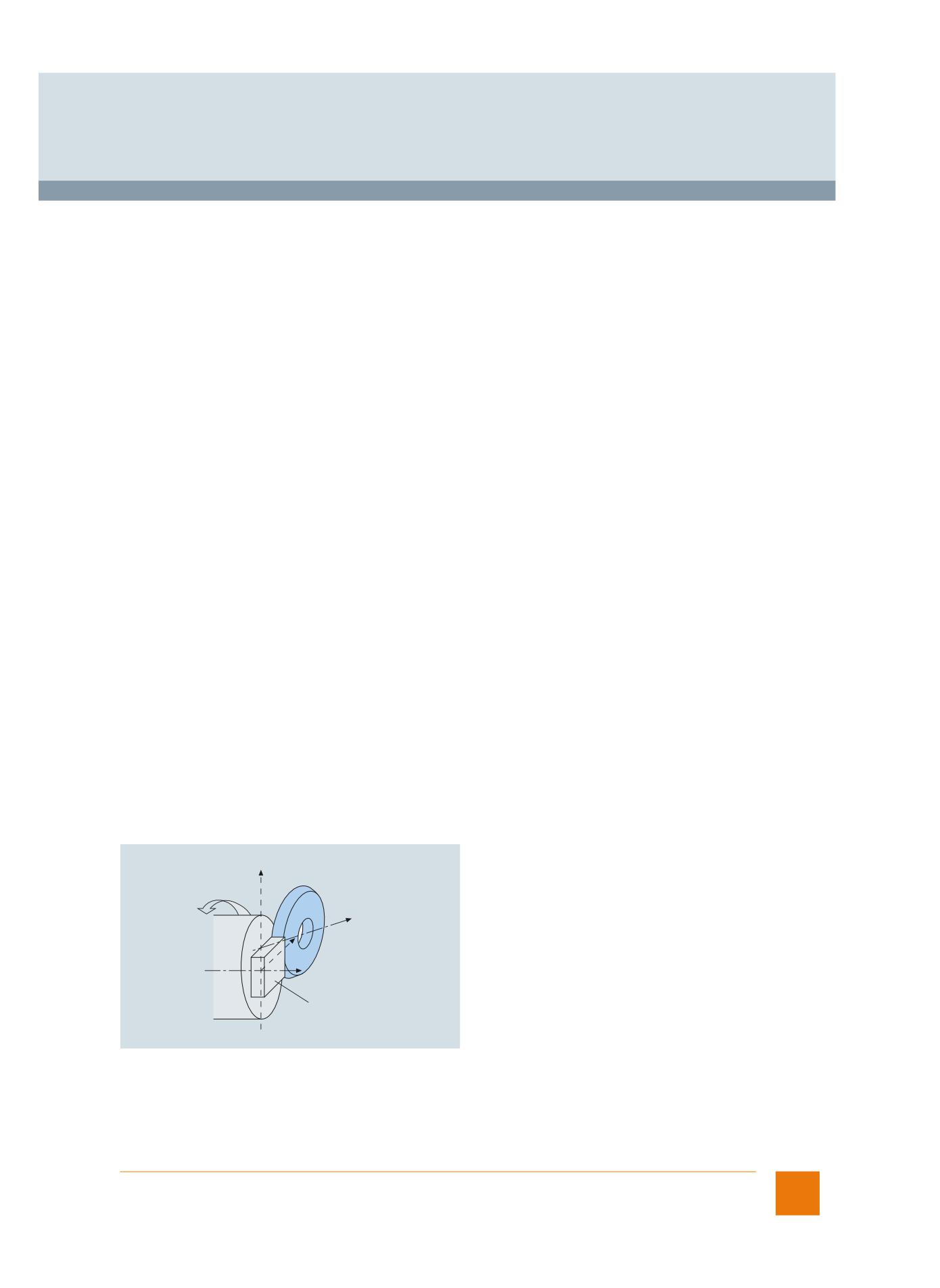
Two transformations can be concatenated using the TRACON command: TRAANG (inclined axis), as the base
transformation, can be linked with TRAORI (5-axis transformation), TRANSMIT (face machining of turned parts) and TRACYL
(cylinder surface transformation).
Applications:
• Turning-milling with mechanical non-orthogonal Y axis to X, Z (inclined-bed turning milling machine)
• Grinding contours programmed with TRACYL (cylinder processing)
• Finishing an out-of-center contour created with TRANSMIT.
TRAANG
Y
Inclined
axis
U
TRANSMIT
X
Z
Workpiece
G_NC01_en_00129
Grinding a TRANSMIT contour with inclined axis
Siemens NC 62 · 2017
13
© Siemens AG 2017
Glossary
Functions and terms
SINUMERIK 840D sl
Continue machining at the contour (retrace support), Run MyCC /RESU
Option; order code M24
Article No.: 6FC5800-0AM24-0YB0
When using 2D flat bed cutting procedures, e.g. laser, oxygen or water jet cutting, the machine operator can return to the program
continuation point (selected solely from the view of the workpiece) following an interruption in machining without exact knowledge of
the part program in order to continue machining the workpiece from that particular location.
The Continue machining at the contour function (retrace support) contains a ring buffer for the geometric information of the blocks
already executed. A new part program is generated from this for reverse travel.
Continue machining is used, for example, when the machine operator only notices the interruption in a 2D laser or water jet cutting
operation a few blocks after the actual interruption. The head has usually already progressed further in the machining process, and
must, therefore, be returned to continue machining.
Continuous dressing (parallel dressing)
With the continuous dressing function, the form of the grinding wheel can be dressed in parallel with the machining process. The
grinding wheel compensation resulting from dressing the wheel takes immediate effect as tool length compensation.
When the tool radius compensation is programmed to machine the contour and the tool radius changes because of the dressing of
the grinding wheel, the CNC computes the dressing amount online as a true tool radius compensation.
Dressing
roll
Profile
dressing
roll
Grinding
wheel
Grinding
wheel
Workpiece
Workpiece
G_NC01_EN_00107
Continuous dressing (parallel dressing)
Continuous-path mode with programmable rounding clearance
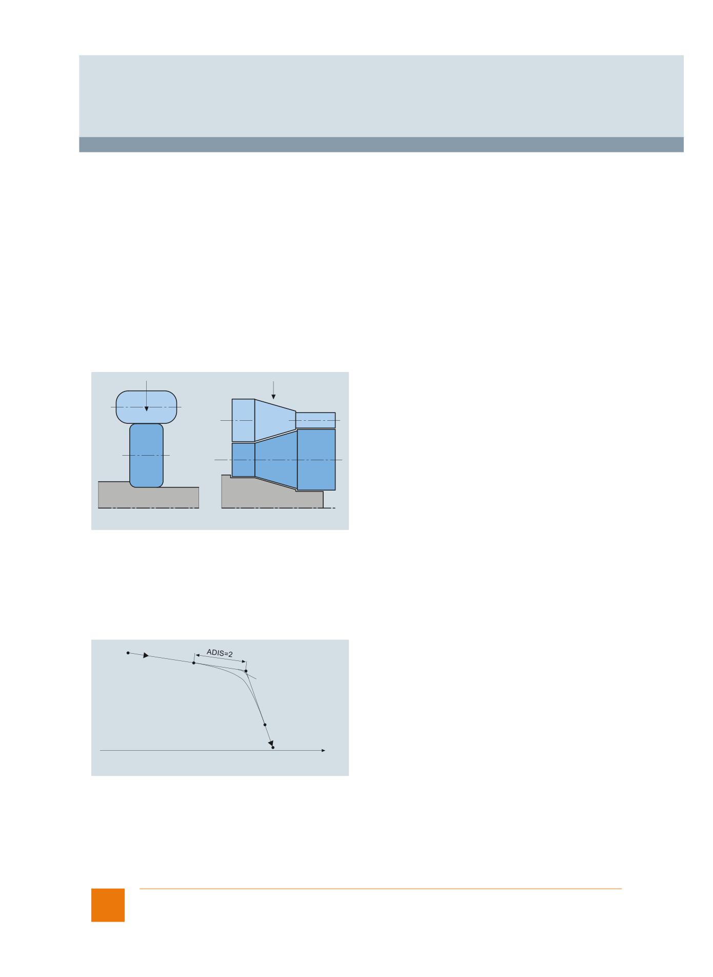
The aim of the continuous-path mode is to avoid excessive deceleration at the block boundaries and to achieve as constant a tool
path velocity as possible during tangential transitions from one block to the next. Because the tool does not stop at block boundaries,
no undercuts are made on the workpiece.
If continuous-path mode G64 is selected, reduction in velocity takes place and contour corners are rounded at non-tangential
transitions. A soft contour transition without a jump in acceleration can be programmed with G641 ADIS=...
P1
P2
G641 ADIS=2
G64
P3
X
G_NC01_XX_00105
Continuous-path mode with programmable rounding clearance
Contour definition programming
Contour definition programming allows you to input simple contours quickly. With the aid of help displays in the editor, you can
program 1-point, 2-point or 3-point definitions with transition elements chamfer or corner easily and clearly by entering Cartesian
coordinates and/or angles.
14
Siemens NC 62 · 2017
© Siemens AG 2017
Glossary
Functions and terms
SINUMERIK 840D sl
Contour handwheel
Option; order code M08
Article No.: 6FC5800-0AM08-0YB0
When the contour handwheel function is activated, the handwheel has a velocity-generating effect in AUTO and MDI CNC operating
modes on all programmed traversing movements of the path and synchronized axes.
A feedrate specified via the CNC program becomes ineffective and a programmed velocity profile is no longer valid. The feedrate,
in mm/min, results from the handwheel pulses as based on pulse weighting (machine data) and the active increment.
The handwheel's direction of rotation determines the direction of travel:
• Clockwise:
In the programmed direction of travel (even beyond block boundaries)
• Counter-clockwise:
Opposite to the programmed direction of travel (continuation beyond the start of the block is prevented).
Feedrate interpolation (feed characteristic)
Contour monitoring
The following error is monitored within a definable tolerance band as a measure of contour accuracy. An impermissibly high following
error might be caused by a drive overload, for example. If an error occurs, the axes/spindles are stopped. Contour monitoring is
always enabled when a channel is active and in position-controlled mode. If the channel is interrupted or in the reset state, contour
monitoring is not active. Contour monitoring is also deactivated during execution of the travel to fixed stop function.
Travel to fixed stop
Contour monitoring with tunnel function
Option; order code M52
Article No.: 6FC5800-0AM52-0YB0
With contour monitoring with tunnel function, the absolute movement of the tool tip in space can be monitored in 5-axis machining
or when complex workpieces are being machined. This function provides optimum protection for high-quality workpieces.
A cylindrical tunnel (tolerance field) with a definable diameter is placed around the programmed path.
If during machining the deviation from the path caused by axis errors is greater than the defined tunnel diameter, the axes are brought
to a standstill immediately. The deviation from the path can be written simultaneously to an analog output.
Coupling, transformation and sensor technology, Run MyCC /PCTS
Option; order code N21
Article No.: 6FC5800-0AN21-0YB0
SINUMERIK Integrate Run MyCC /PCTS is a package for coupling, transformation and sensor technology.
No general application.
Restricted functionality of export versions:
Not possible.
Crank interpolation, Run MyCC /CRIP
Option; order code N04
Article No.: 6FC5800-0AN04-0YB0
The SINUMERIK Integrate Run MyCC /CRIP crank interpolation function supports simple programming and machining of pin bearing
seats on a crankshaft. The function can be utilized in more than one channel, which means that a single workpiece can be machined
simultaneously with several grinding units. The function calculates the compensating movement of the grinding wheel in relation to
the rotating workpiece surface. As with normal cylindrical grinding, the pin bearing journal is programmed as a radial distance X
between the workpiece and the grinding wheel.
Restricted functionality of export versions:
Not possible.
Siemens NC 62 · 2017
15
© Siemens AG 2017
Glossary
Functions and terms
SINUMERIK 840D sl
Cross-mode actions ASUB and synchronized actions
Option; order code M43
Article No.: 6FC5800-0AM43-0YB0
Asynchronous subprograms ASUB make it possible to respond immediately to high-priority events not only during program execu-
tion, but in all CNC operating modes and program states. In the case of such an interrupt, it is possible to start an asynchronous
subprogram in JOG. The asynchronous subprogram can be used, for example, to bring the grinding wheel to a safe position to avoid
collision.
This option also enables statically effective IDS synchronized actions, which are active in all CNC operating modes.
Interrupt routines with fast retraction from the contour
Cycle protection
Lock MyCycles
Cycle support
The technology cycles for drilling, milling and turning and the measuring cycles are supported by cycle screens. Similar input
screens are also available to program contours. Users can also define their own softkeys, input fields and displays using
"SINUMERIK Operate runtime license OA Easy Screen".
Use HMI applications, Run MyScreens
16
Siemens NC 62 · 2017

© Siemens AG 2017
Glossary
Cycle overview
SINUMERIK 840D sl
Overview of cycles - couplings
Coupled-motion axes (TRAIL)
Basic scope
CYCLE700 generic coupling: TRAILON
CYCLE701 generic coupling: TRAILOF
Synchronous spindle/multi-edge turning
Shell cycle for program compatibility with
CYCLE704 generic coupling: COUPDEF
(COUP) replaced by
6FC5800-0AM14-0YB0
CYCLE705 generic coupling: COUPON
Generic coupling
CYCLE706 generic coupling: COUPONC
CYCLE707 generic coupling: COUPOF
CYCLE708 generic coupling: COUPOFS
CYCLE709 generic coupling: COUPDEL
CYCLE710 generic coupling: COUPRES
Master value coupling and curve table
Shell cycle for program compatibility with
CYCLE702 generic coupling: LEADON
interpolation (LEAD) replaced by
6FC5800-0AM20-0YB0
CYCLE703 generic coupling: LEADOF
Generic coupling
Electronic gear function (EG) replaced by
Shell cycle for program compatibility with
CYCLE711 generic coupling: EGDEF
Generic coupling
6FC5800-0AM22-0YB0
CYCLE712 generic coupling: EGON
CYCLE713 generic coupling: EGONSYN
CYCLE714 generic coupling: EGONSYNE
CYCLE715 generic coupling: EGOFC
CYCLE716 generic coupling: EGOFS
CYCLE717 generic coupling: EGDEL
Generic coupling CP-Standard
Basic scope
CYCLE700 generic coupling: TRAILON
CYCLE701 generic coupling: TRAILOF
Generic coupling CP-Static
6FC5800-0AM75-0YB0
CYCLE700 generic coupling: TRAILON
CYCLE701 generic coupling: TRAILOF
Generic coupling CP-Basic
6FC5800-0AM72-0YB0
CYCLE702 generic coupling: LEADON
CYCLE703 generic coupling: LEADOF
CYCLE704 generic coupling: COUPDEF
CYCLE705 generic coupling: COUPON
CYCLE706 generic coupling: COUPONC
CYCLE707 generic coupling: COUPOF
CYCLE708 generic coupling: COUPOFS
CYCLE709 generic coupling: COUPDEL
CYCLE710 generic coupling: COUPRES
Generic coupling CP-Comfort
6FC5800-0AM73-0YB0
CYCLE700 generic coupling: TRAILON
CYCLE701 generic coupling: TRAILOF
Generic coupling CP-Expert
6FC5800-0AM74-0YB0
CYCLE702 generic coupling: LEADON
CYCLE703 generic coupling: LEADOF
CYCLE704 generic coupling: COUPDEF
CYCLE705 generic coupling: COUPON
CYCLE706 generic coupling: COUPONC
CYCLE707 generic coupling: COUPOF
CYCLE708 generic coupling: COUPOFS
CYCLE709 generic coupling: COUPDEL
CYCLE710 generic coupling: COUPRES
CYCLE711 generic coupling: EGDEF
CYCLE712 generic coupling: EGON
CYCLE713 generic coupling: EGONSYN
CYCLE714 generic coupling: EGONSYNE
CYCLE715 generic coupling: EGOFC
CYCLE716 generic coupling: EGOFS
CYCLE717 generic coupling: EGDEL
Siemens NC 62 · 2017
17

© Siemens AG 2017
Glossary
Cycle overview
SINUMERIK 840D sl
Overview of cycles - interpolation, measurement
Advanced Surface
6FC5800-0AS07-0YB0
CYCLE832 high-speed settings
Measuring cycles
6FC5800-0AP17-0YB0
CYCLE150 Measurement: Measurement result (measurement result display and
selection/deselection of log)
CYCLE961 milling measurement: Corner - right-angled corner/any corner
CYCLE971 milling measurement: Measure tools
CYCLE971 milling measurement: Measure tools - calibrate tool probe
CYCLE973 turning measurement: Calibrate probe - length/radius at surface/
radius in slot
CYCLE974 turning measurement: Inner/outer diameter
CYCLE976 milling measurement: Calibrate probe - length/radius in ring/
radius at edge/calibrate on sphere
CYCLE977 milling measurement: Hole/rectangular pocket
CYCLE977 milling measurement: Edge distance - slot/web
CYCLE977 milling measurement: Circular/rectangular spigot
CYCLE978 milling measurement: Edge distance - set edge
CYCLE979 milling measurement: Hole/inner circle segment
CYCLE979 milling measurement: Spigot/outer circle segment
CYCLE982 turning measurement: Measure tools (turning tools, milling tools, drills)
CYCLE982 turning measurement: Measure tools - calibrate tool probe
CYCLE994 turning measurement: Inner/outer diameter
CYCLE995 milling measurement: Measure 3D - angular deviation spindle
CYCLE997 milling measurement: Measure 3D - 1 sphere/3 spheres
CYCLE998 milling measurement: Measure 3D - align plane
CYCLE998 milling measurement: Edge distance - align edge
CUST_MEACYC Manufacturer cycle for measuring cycles
(formerly CYCLE198 and CYCLE199)
Measure kinematics
6FC5800-0AP18-0YB0
NoCYCLE996 milling measurement: Measure 3D - measure kinematics
Overview of cycles - programming language
Online ISO dialect
Basic scope
CYCLE301 ISO internal subprogram: Data conversion inch/metric
Interpreter
CYCLE305 ISO high-precision contour control (G05)
CYCLE308 ISO-M look-ahead control (G08)
CYCLE3106 ISO lift rapid (G10.6)
CYCLE322 ISO working area limitation set (G22)
CYCLE323 ISO working area limitation cancel (G23)
CYCLE328 ISO first reference point return (G28/G27/G30.1)
CYCLE330 ISO 2.3.4. reference point return (G30)
CYCLE3512 ISO-T polygonal turning (G50.2/G51.2)
CYCLE370T ISO-T finishing (G70)
CYCLE371T ISO-T longitudinal turning (G71/G77)
CYCLE3721 ISO-M contour repeating (G72.1/G72.2)
CYCLE372T ISO-T face turning (G72/G79)
CYCLE373T ISO-T pattern repeating (G73)
CYCLE374T ISO-T deep hole drilling and recessing (G74/G75)
CYCLE375T ISO-T deep hole drilling and recessing
CYCLE376T ISO-T thread cutting (G78/G76)
CYCLE381M ISO-M drilling (G81/G82/G85/G86/G89)
CYCLE383M ISO-M drilling (G73/G83)
CYCLE383T ISO-T deep hole drilling (G83/G87)
CYCLE3841 ISO-M rigid tapping
CYCLE384M ISO-M tapping (G74/G84)
CYCLE384T ISO-T tapping (G84/G88)
CYCLE385T ISO-T drilling (G85/G89)
CYCLE387M ISO-M drilling (G76/G87)
CYCLE395 ISO-T roughing
CYCLE396 ISO interrupt program call (M96)
CYCLE398 ISO-T threading
CYCLE861 ISO-M back boring
18
Siemens NC 62 · 2017

© Siemens AG 2017
Glossary
Cycle overview
SINUMERIK 840D sl
Overview of cycles - programming support
Technological cycles
Basic scope
CUST_800 Manufacturer cycle for swiveling (formerly TOOLCARR)
drilling/milling/turning
CUST_832 Manufacturer cycle for high speed settings (formerly CYC_832T)
CUST_M6 Manufacturer cycle for tracking tool changes with SERUPRO
CUST_MULTICHAN Manufacturer cycle for multi-channel editor
CUST_T Manufacturer cycle for tracking tool changes with SERUPRO
CUST_TECHCYC Manufacturer cycle for technology cycles (formerly ST_CUST)
CYCLE60 milling: Engraving
CYCLE61 milling: Face milling
CYCLE62 contour turning and milling: Contour - contour call
CYCLE63 contour milling: Pocket, spigot, all with residual material
CYCLE64 contour milling: Predrilling
CYCLE70 milling: Thread milling
CYCLE71 milling compatibility with 802D sl: Face milling
CYCLE72 contour milling: Path
CYCLE76 milling: Spigot - rectangular spigot
CYCLE77 milling: Spigot - circular spigot
CYCLE78 drilling: Thread - drill thread milling
CYCLE79 milling: Multi-edge spigot
CYCLE800 milling: Swivel plane, align tool
CYCLE801 drilling: Positions - grid or frame
CYCLE802 drilling: Positions - any positions
CYCLE81 drilling: Centering
CYCLE82 drilling: Drilling reaming - drilling
CYCLE83 drilling: Deep-hole drilling 1
CYCLE830 drilling: Deep-hole drilling 2
CYCLE832 milling: High-speed settings
CYCLE84 drilling: Thread - rigid tapping
CYCLE840 drilling: Thread - tapping with compensating chuck
CYCLE85 drilling: Drilling reaming - reaming
CYCLE86 drilling: Boring
CYCLE87 drilling compatibility with 802D sl: Boring pass 3
CYCLE88 drilling compatibility with 802D sl: Boring with stop
CYCLE89 drilling compatibility with 802D sl: Boring pass 5
CYCLE899 milling: Slot - open slot
CYCLE90 milling compatibility with 802D sl: Thread milling
CYCLE92 turning: Parting
CYCLE93 turning compatibility with 802D sl: Grooving
CYCLE930 turning: Grooving
CYCLE94 turning compatibility 802D sl: Undercut form E and F
CYCLE940 turning: Undercut - form E, form F, undercut thread DIN, undercut thread
CYCLE95 turning compatibility stock removal (with SW 2.5 and 802D sl)
CYCLE951 turning: Stock removal
CYCLE952 contour turning: Stock removal, plunging, plunge cutting, all with residual
material
CYCLE96 turning compatibility 802D sl: Thread undercut form A, B, C, D
CYCLE97 turning compatibility 802D sl: Thread cutting
CYCLE98 turning: Thread - thread chain
CYCLE99 turning: Thread - longitudinal, taper, face
HOLES1 drilling: Positions - row of holes
HOLES2 drilling: Positions - circle of holes
LONGHOLE milling: Slot - elongated hole
POCKET3 milling: Pocket - rectangular pocket
POCKET4 milling: Pocket - circular pocket
PROG_EVENT ASUB for supporting special modes
SLOT1 milling: Slot - longitudinal groove
SLOT2 milling: Slot - circumferential groove
Pocket milling with free
Basic scope
CYCLE63 milling contour pocket: Residual material detection
contour definition and
CYCLE64 predrilling contour pocket: Residual material detection
islands
Residual material
6FC5800-0AP13-0YB0
CYCLE63 milling contour pocket: Residual material detection
detection and machining
CYCLE64 predrilling contour pocket: Residual material detection
for contour pockets and
CYCLE952 stock removal along contour: Residual material detection
stock removal
Siemens NC 62 · 2017
19

© Siemens AG 2017
Glossary
Cycle overview
SINUMERIK 840D sl
Overview of cycles - programming support
ShopTurn/ShopMill
6FC5800-0AP17-0YB0
E_CALL subprogram
machining step
E_CI_CO contour spigot
programming (ShopMill)
E_CI_RE contour spigot residual material
E_CLAMP multiple clamping
E_CON contour
E_CONFIG settings
E_CP_CE centering a contour pocket
E_CP_CO solid machining a contour pocket
E_CP_DR predrilling a contour pocket
E_CP_RE contour pocket residual material
E_CR_HEL helix
E_DR drilling
E_DR_BGF drill and thread milling
E_DR_BOR boring
E_DR_PEC deep-hole drilling 1
E_DR_PEC2 deep-hole drilling 2
E_DR_REA reaming
E_DR_SIN countersinking
E_DR_TAP tapping
E_END end of program
E_HEAD program header
E_MC_LP calibrate workpiece probe: Length on surface
E_MC_MPT calibrate tool probe calibrate (tool probe)
E_MC_RC calibrate workpiece probe radius at edge
E_MC_RR calibrate workpiece probe radius in ring
E_MC_RSP calibrate workpiece probe radius on sphere
E_MI_CON path milling
E_MI_EDG multi-edge
E_MI_PL face milling
E_MI_TR thread milling
E_MI_TXT engraving cycle
ShopTurn/ShopMill
6FC5800-0AP17-0YB0
F_BARLO bar loader
machining step
F_CI_CO contour spigot
programming (ShopTurn)
F_CI_RE contour spigot residual material
F_CON contour
F_CONFIG settings
F_CP_CE centering a contour pocket
F_CP_CO solid machining a contour pocket
F_CP_DR predrilling a contour pocket
F_CP_RE contour pocket residual material
F_DR drilling
F_DR_BGF drill thread milling
F_DR_BOR boring
E_DR_PEC deep-hole drilling 1
F_DR_PEC2 deep-hole drilling 2
F_DR_REA reaming
F_DR_SIN countersinking
F_DR_TAP tapping
F_DRILL deep-hole drilling centered
F_END end of program
F_GROOV grooving
F_HEAD program header
F_HOME tool change point
F_MC_FCE measurement: Front edge
F_MC_L calibrate workpiece probe: Length
F_MC_LP calibrate workpiece probe: Length on surface
F_MC_MPT calibrate tool probe calibrate (tool probe)
F_MC_R calibrate workpiece probe: Radius
F_MC_RC calibrate workpiece probe radius at edge
F_MC_RR calibrate workpiece probe: Radius in ring
20
Siemens NC 62 · 2017

© Siemens AG 2017
Glossary
Cycle overview
SINUMERIK 840D sl
Overview of cycles - programming support
ShopTurn/ShopMill
6FC5800-0AP17-0YB0
F_MC_RSP calibrate workpiece probe: Radius on sphere
machining step
F_MC_SL measure workpiece slot
programming (ShopTurn)
F_MP_3SP measurement: 3 spheres
(continued)
F_MP_BAR measurement: Web
F_MP_C90 measurement: Right-angled corner
F_MP_COR measurement: Any corner
F_MP_CSI measurement: Inner circle segment
F_MP_CSO measurement: Outer circle segment
F_MP_DMI measurement: Inner diameter
F_MP_DMO measurement: Outer diameter
F_MP_DR measurement: Bore hole
F_MP_EDG measurement: Edge
F_MP_LIN measurement: Align edge
F_MP_PIC measurement: Circular spigot
F_MP_PIR measurement: Rectangular spigot
F_MP_PL measurement: Align plane
F_MP_POR measurement: Rectangular pocket
F_MP_SL measurement: Slot
F_MP_SPH measurement: Sphere
F_MT_DR measurement: Drilling tools
F_MT_MIL measurement: Milling tools
F_MT_TUR measurement: Turning tools
F_MI_CON path milling
F_MI_EDG multi-edge
F_MI_PL face milling
F_MI_TR thread milling
F_MI_TXT engraving cycle
F_PARTOF parting
F_PI_CIR circular spigot
F_PI_REC rectangular spigot
F_PO_CIR circular pocket
F_PO_REC rectangular pocket
F_PS_CIR position circle
F_PS_FRA position frame
F_PS_MRX position matrix
F_PS_ROW position row
F_PS_SEQ position sequence
F_REL_BC retraction with swivel
F_RELEAS retraction
F_ROT_C C translation
F_ROU_Z extended stock removal
F_ROUGH stock removal corner
F_SL_CIR circumferential groove
F_SL_LON longitudinal groove
F_SL_OPN open slot
F_SUB_SP counterspindle
F_SWIV_H swiveling
F_TAP tapping centered
F_TCARR swiveling
F_TCTOOL setting tool
F_TR_CHN thread cutting thread chain
F_TR_CON cutting taper thread
F_TR_LON cutting longitudinal thread
F_TR_PLA face thread cutting
F_TS tool
F_UCUT_D undercut DIN
F_UCUT_E undercut form E
F_UCUT_F undercut form F
F_UCUT_T undercut thread
F_TR_LON cutting longitudinal thread
Siemens NC 62 · 2017
21

© Siemens AG 2017
Glossary
Cycle overview
SINUMERIK 840D sl
Overview of cycles - commissioning functions
Friction compensation
6FC5800-0AS06-0YB0
CYCLE790
with adaptive
characteristics
Automatic servo tuning
6FC5800-0AS10-0YB0
CYCLE750 AST command: Internal cycle
CYCLE751 AST command: Open / perform / close an optimization session
CYCLE752 AST command: Add axis to an optimization session
CYCLE753 AST command: Select optimization mode
CYCLE754 AST command: Add / remove data set
CYCLE755 AST command: Back up / restore data
CYCLE756 AST command: Activate optimization results
CYCLE757 AST command: Save optimization information
CYCLE758 AST command: Change parameter value
CYCLE759 AST command: Read parameter value
22
Siemens NC 62 · 2017
© Siemens AG 2017
Glossary
Functions and terms
SINUMERIK 840D sl
Data exchange between machining channels
In the program coordination function, variables shared by the channels (NCK-specific global variables) can be used for data
exchange between the programs. The program message itself is separate for each channel.
CNC high-level language
Develop compile cycles, Create MyCC
Article No.: on request
The openness in the NC kernel permits the user to expand the real-time area of the SINUMERIK CNC through the development of
customized compile cycles using SINUMERIK Integrate Create MyCC.
Restricted functionality of export versions:
Not possible.
Execute compile cycles, Run MyCC
Develop compile cycles on a user-specific interface, Create MyCCI
Article No.: 6FC5863-1YP00-0YB8
SINUMERIK Integrate Create MyCCI supports the development of loadable compile cycles based on application-specific interfaces
with a predefined development environment. For this special application, the customer uses development tools (GNU com-
piler/linker) in a Cygwin software shell on a Windows PC. The concept allows OEMs to develop their own applications in C/C++ and
to load them as their own compile cycles.
Compile cycles interface, Run MyCCI /xy
Diagnostic functions
For service purposes, a self-diagnostics program and testing aids have been integrated in the CNCs. The status of the following can
be displayed on the operator panel:
• Interface signals between the CNC and the PLC and between the PLC and the machine
• Data blocks
• PLC bit memories, timers and counters
• PLC inputs and outputs
For test purposes, output signals, input signals, and bit memories can be set. All alarms and messages are displayed in plain text
on the operator panel along with the corresponding delete criterion. Alarms and messages are displayed separately.
In the Service display menu, it is possible to call up important information about the axis and spindle drives, such as:
• Absolute actual position
• Position setpoint
• Following error
• Speed setpoint
• Actual speed value
• Trace of CNC and drive variables
Differential tower transformation, Run MyCC /DTOW
Option; order code N68
Article No.: 6FC5800-0AN68-0YB0
SINUMERIK Integrate Run MyCC /DTOW is a specific function and is not intended for general use.
Restricted functionality of export versions:
Not possible.
Display external positions, Run MyCC /EXPD
Option; order code N64
Article No.: 6FC5800-0AN64-0YB0
SINUMERIK Integrate Run MyCC /EXPD can be used to display external positions of a robot coupled via a command interface in
SINUMERIK Operate. The WCS and MCS positions of the robot are displayed in the machine basic screen of the robot channel. The
target positions to be approached by the robot are programmed in the NC part program as parameters of a cycle call. The cycle
writes the commands to the communications buffer variables $A_DBR and $A_DBD between the NC and PLC. The PLC transfers
them to the robot control.
Operate robot, Run MyRobot
Siemens NC 62 · 2017
23
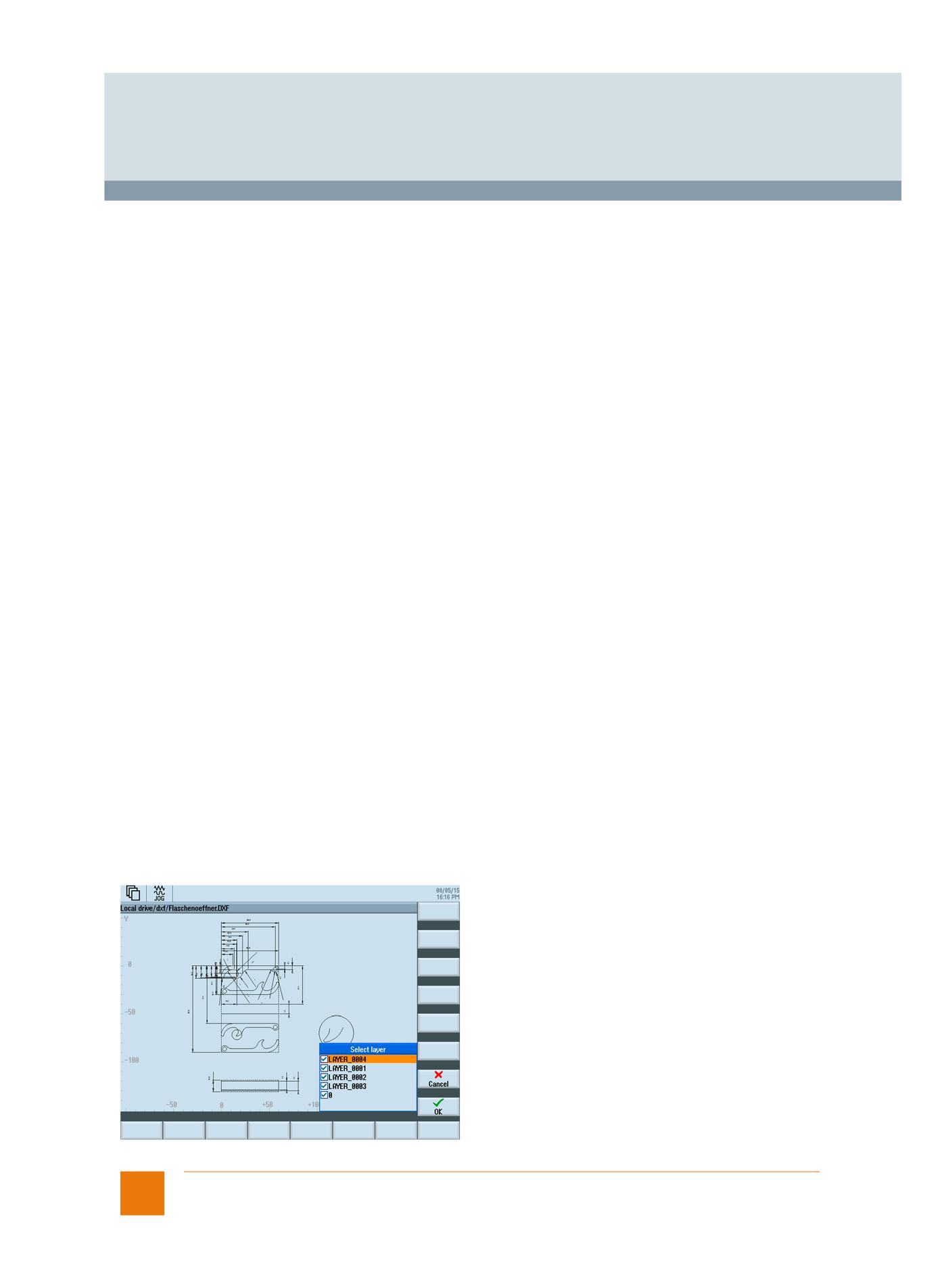
© Siemens AG 2017
Glossary
Functions and terms
SINUMERIK 840D sl
Display functions
All current information can be displayed on the operator panel's screen:
• Block currently being executed
• Previous and following block
• Actual position, distance-to-go
• Current feedrate
• Spindle speed
• G functions
• Auxiliary functions
• Workpiece name
• Main program name
• Subprogram name
• All data entered, such as part programs, user data and machine data
• Help texts, tooltips
Important operating states are displayed in plain text, for example:
• Alarms and messages
• Position not yet reached
• Feedrate stop
• Program is running
DRF offset (differential resolver function)
The differential resolver function generates an additional incremental work offset in Automatic mode via the electronic handwheel.
This function can be used, for example, to correct tool wear within a programmed block.
Handwheel override
Drive current measurement, Run MyCC /KPXT
Option; order code M82
Article No.: 6FC5800-0AM82-0YB0
SINUMERIK Integrate Run MyCC /KPXT is a specific function and is not intended for general use.
Auto Servo Tuning AST
Restricted functionality of export versions:
Not possible.
DXF Reader
Option; order code P56
Article No.: 6FC5800-0AP56-0YB0
The DXF Reader option allows DFX files to be opened directly on the CNC within SINUMERIK Operate so that contours and points
can be extracted from the files.
24
Siemens NC 62 · 2017
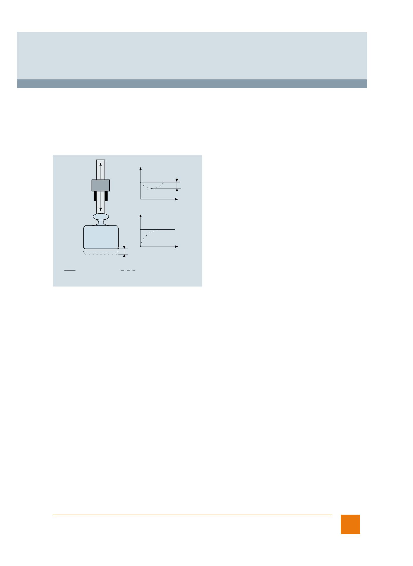
© Siemens AG 2017
Glossary
Functions and terms
SINUMERIK 840D sl
Electronic counterweight
With weight-loaded axes without mechanical or hydraulic weight counterbalance, the vertical axis drops when the brake is released
and the servo enable is switched on. The undesired lowering dZ of the axis can be compensated by activating electronic weight
counterbalance. After releasing the brake, the constant weight counterbalance torque maintains the position of the vertical axis.
Sequence:
1. Brake holds Z axis
2. Brake is released; controller enable on; pulse enable on.
3. Z axis does not drop, but holds its position.
+Z
Path
Z
Feed
drive
dZ
Brake
t
-Z
Torque
Weight
t
dZ
Electronic weight counterbalance
With electronic weight
Without electronic weight
counterbalance
counterbalance
G_NC01_EN_00109
Electronic counterweight
Electronic gear
The electronic gear function allows highly accurate kinematic coupling of axes with programmable gear ratio. Linking can be
specified and selected for any CNC axes via program or operator panel.
The electronic gear function makes it possible to control the movement of a following axis, depending on up to 5 leading axes.
The relations between the leading axis and the following axis are defined for each leading axis by a fixed gear ratio (numerator/
denominator) or as a linear or non-linear coupling using a curve table. The following axis can be a leading axis for another gear
system (cascading).
Real as well as simulated linear and rotary axes can be used as the leading and following axes. Master input values can be setpoints
generated by the interpolator (setpoint linkage) or actual values delivered by the measuring system (actual-value linkage). Using the
electronic gear with non-linear coupling, it is possible to create convex tooth faces during gear cutting and also to compensate the
non-linear properties of the process, for example.
Restricted functionality of export versions:
The number of simultaneously traversing axes is restricted to 4.
Generic coupling
Electronic handwheels
Using electronic handwheels, it is possible to move selected axes simultaneously in manual mode. The handwheel clicks are
analyzed by the increment analyzer. If coordinate offset or coordinate rotation is selected, it is also possible to move the axes
manually in the transformed workpiece coordinate system.
The maximum input frequency of the handwheel inputs is 100 kHz. A third handwheel can also be operated as a contour handwheel.
The Contour handwheel function permits use of a handwheel on conventional turning machines (for ShopTurn applications, for
example) and also during grinding for traversing on a contour.
Once the Contour handwheel function has been activated, the handwheel has a velocity-generating effect in AUTO and MDI CNC
operating modes, i.e. a feedrate specified via the CNC program is no longer effective and a programmed velocity profile is no longer
valid. The feedrate, in mm/min, results from the handwheel pulses as based on pulse evaluation via machine data and the active
increment INC1, INC10,
The handwheel's direction of rotation determines the direction of travel: clockwise in the programmed direction, even over block
boundaries, and counter-clockwise up to the block start.
Siemens NC 62 · 2017
25
© Siemens AG 2017
Glossary
Functions and terms
SINUMERIK 840D sl
Electronic Key System EKS
Option; order code P53
Article No.: 6FC5800-0AP53-0YB0
Support of the Electronic Key System (EKS) in SINUMERIK MPPs (Machine Pushbutton Panels)
Electronic transfer CP
Option; order code M76
Article No.: 6FC5800-0AM76-0YB0
In presses with transfer step tools as well as in large-part transfer presses, a modern transfer system handles part transport.
Positioning drives are controlled in step with the press's main motion. The Electronic transfer CP makes it possible to control motion
sequences in transfer systems, such as gripper rails or suction systems, etc., depending on a master value which corresponds to
the current ram position of the press.
The electronic transfer CP includes the options:
• Position switching signals/cam controller
• Polynomial interpolation
• Generic coupling CP-Comfort
• Cross-mode actions ASUB and synchronized actions
• I/O interfacing via PROFIBUS DP
• Synchronized actions stage 2
• Pairs of synchronous axes (gantry axes)
Combinations of these individual options satisfy all requirements for highly dynamic and positionally accurate transfer controls.
When using the Electronic transfer CP option, the spindle and tool offset functions cannot be activated.
Restricted functionality of export versions:
The number of simultaneously traversing axes is restricted to 4.
Position switching signals/cam controller
Polynomial interpolation
Generic coupling CP-Comfort
Cross-mode actions ASUB and synchronized actions
I/O interfacing via PROFIBUS DP and PROFINET
Synchronized actions stage 2
Pair of synchronous axes (gantry axes)
Engineered motion control, Run MyCC /EMC
Option; order code N47
Article No.: 6FC5800-0AN47-0YB0
SINUMERIK Integrate Run MyCC /EMC optimizes the feedforward control of axes by application of a mechatronic model.
Mechatronic support provided by Siemens assists with calculation of the axis model and parameterization of the filters that will act
on the position setpoint and the feedforward control branches in real time.
The improved vibration behavior exhibited by the machine axes results in greater machining precision and often makes it possible
to increase the jerk limitation settings in order to boost machine productivity.
Restricted functionality of export versions:
Not possible.
Engineering:
Automated commissioning, Create MyConfig
SINUMERIK Integrate Create MyConfig supports the automated commissioning of machines with SINUMERIK CNCs. Thanks to the
modular concept, the software allows different machines of a series to be commissioned and upgraded with only a single software
module.
The benefits to the user are a reduction in the time taken to perform commissioning and upgrades, avoidance of associated errors
thanks to simplified commissioning and upgrade procedures and automated process sequences.
26
Siemens NC 62 · 2017
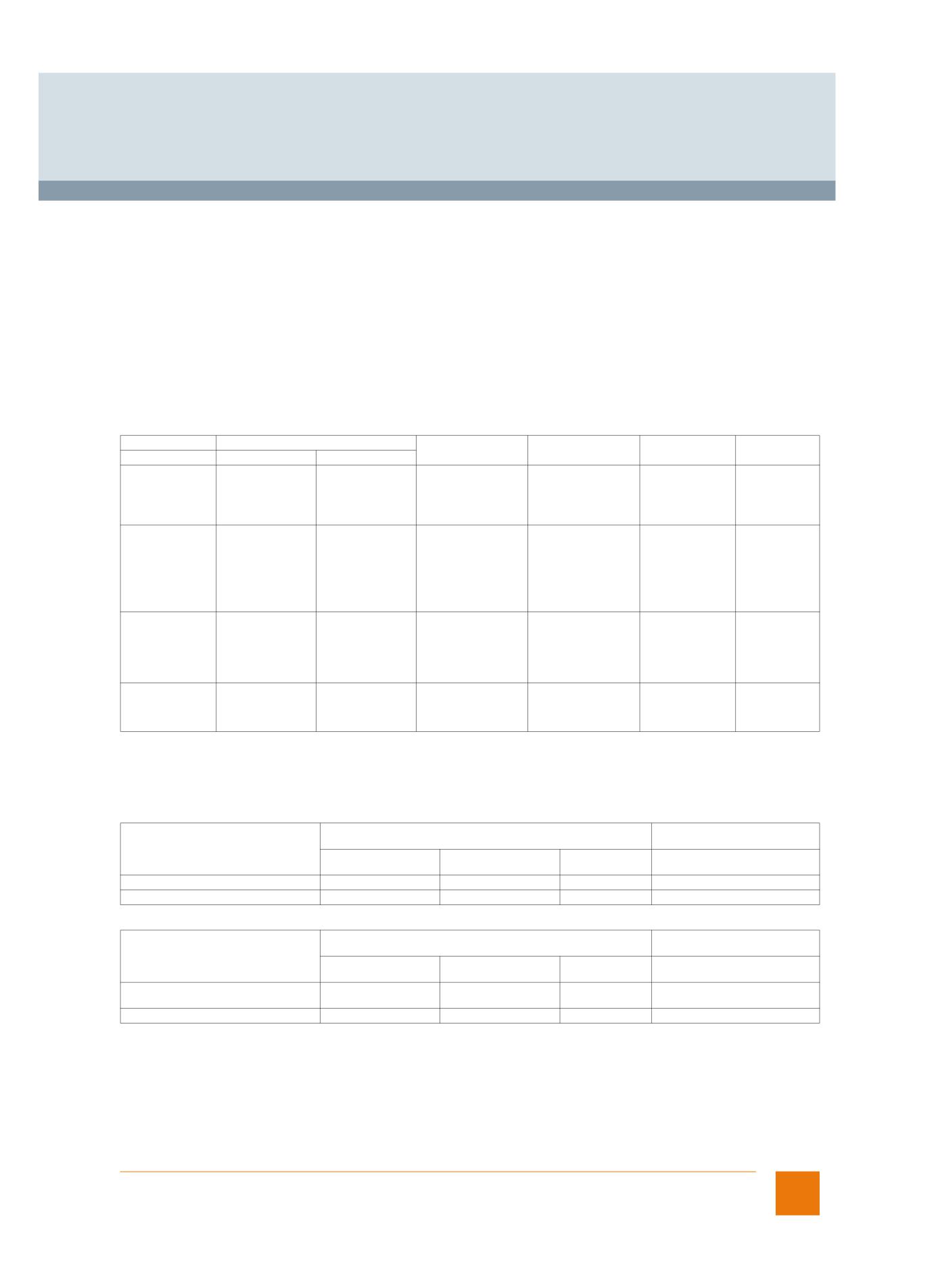
© Siemens AG 2017
Glossary
Functions and terms
SINUMERIK 840D sl
Engineering:
Commissioning series machines
Files called series start-up files can be generated to enable transfer of a particular configuration, in its entirety, to other CNCs that
use the exact same software version, for example, CNCs that are to be used for the same machines.
Series start-up means bringing a series of CNCs to the same initial state as regards their data. You can archive/read selected CNC,
PLC and PCU data for series start-up. Compensation data can be optionally saved. The drive data are stored as binary data, and
cannot be modified.
Series start-ups can even be easily performed without a programming device: Simply create a startup file in the PCU, save it on a
PC card in the CNC, insert this card in the next CNC, and begin the series start-up procedure. Series start-ups can also be performed
via a network drive or a USB stick.
Engineering:
Configure, start up, optimize, service
Preferred tools for configuring, start-up, optimization and service
SINUMERIK Operate
SINUMERIK Integrate
SINUMERIK Integrate
SIMATIC STEP 7
SinuCom NC
Auto Servo Tuning
Create MyConfig
Access MyMachine
Configure
Optimize individual
Modular machines,
Adapt user alarms,
Configure, e.g.
-
(without machine)
or grouped axes
series machines with
integrate user screens,
tool management
retrospectively
variations
tool management,
offline using
bootstick
customer data
Commissioning
1. Axes,
Edit data with UPDiff.
Access SINUMERIK
Read in HW
SinuCom
(at the machine)
axis-drive assign-
Axis-drive assign-
Operate and the
configuration, PLC,
NC-SI
ment, compensa-
ment, adapt topology
active file system
e.g. configure
acceptance
tions
directly
DB18, transfer
test
user program
2. Safety Integrated
incl. acceptance
test and DB-SI
Optimize
Optimize axes
Automatically
Adapt optimization
SinuCom
manually, current,
optimize individual
data, possibly by
NC Trace
speed and position
or grouped axes
remote access
controller.
Filter settings,
trace, …
Service
Troubleshoot
Automatically
Expand machine
Remote access via
Troubleshoot,
SinuCom
optimize individual
TS Adapter
optimize
NC Trace
or grouped axes
processes
Diagnostics
retrospectively
Engineering:
Starting up drives and backing up drive data
Options for starting up drives and backing up drive data. As a general rule, SIMATIC STEP 7 must be installed in the CNC in order
to start up drives (hardware configuration, PLC user program and basic program)
With SINUMERIK Operate
Internal drives (NCU,NX) and external drives (DP,PN)
Via terminals
(with bus system)
(without bus system)
NCK drives
PLC axes
PLC axes
Traversing commands via
(FC18)
(FB283)
terminal I/Os
Commissioning
✔
✔
✔
-
Back up drive data in drive archive
✔
✔
✔
-
With Starter
Internal drives (NCU,NX) and external drives (DP,PN)
Via terminals
(with bus system)
(without bus system)
NCK drives
PLC axes
PLC axes
Traversing commands via
(FC18)
(FB283)
terminal I/Os
Commissioning
✔ (current/speed
✔ (current/speed
✔
✔
controller level only)
controller level only)
Back up drive data in drive archive
✔
✔
✔
✔
Siemens NC 62 · 2017
27
© Siemens AG 2017
Glossary
Functions and terms
SINUMERIK 840D sl
Evaluation of internal drive variables
Option; order code M41
Article No.: 6FC5800-0AM41-0YB0
The evaluation of internal drive variables can be used to control, i.e. by adaptive control, a second process variable (such as a path-
specific or axis-specific feedrate) depending on a measured process variable, e.g. spindle current. This permits, for example, the
cutting volume to be kept constant when grinding, or closing the grinding gap faster when scratching (first touch).
Evaluation of these drive variables also permits machines and tools to be protected from overload; this evaluation also facilitates
shorter machining times and an improved surface quality of the workpiece. Evaluation of internal drive variables is a requirement for
implementing adaptive control (AC). Adaptive control can be parameterized within the part program as follows:
• Additive influence:
The programmed value (F word) is corrected by adding.
• Multiplicative influence:
The F word is multiplied by a factor (override).
The following real-time variables can be evaluated as internal drive variables:
$AA_LOAD drive capacity utilization in %
$AA_POWER drive active power in W
$AA_TORQUE drive torque setpoint in Nm
$AA_CURR actual axis/spindle current in A
Execute compile cycles, Run MyCC
Option; order code M04
Article No.: 6FC5800-0AM04-0YB0
SINUMERIK Integrate Run MyCC enables users to execute compile cycles which they have developed themselves.
Develop compile cycles, Create MyCC
Restricted functionality of export versions:
Not possible.
Execution from external storage EES
Option; order code P75
Article No.: 6FC5800-0AP75-0YB0
When option "Execution from external storage" (EES) is installed, it is possible to execute part programs from external memories
without EXTCALL. A machine with several NCUs can use a common part program memory. The size of the part program memory is
virtually unlimited.
Extended stop and retract ESR (CNC-controlled and drive-autonomous)
Option; order code M61
Article No.: 6FC5800-0AM61-0YB0
A safe position is assumed from the machining level without any collision between tool and workpiece. As well as the drive-autono-
mous stop and retract function, the CNC-controlled stop and retract function is also available. To permit gentle interpolated retraction
along the path or contour, the path interpolation can be processed further for a definable period following the trigger event.
The retraction axes are subsequently traversed in synchronism to an absolute or incremental position as programmed. These
functions are primarily used for gearing and grinding technologies.
Extended stop and retract ESR, drive-autonomous
Option; order code M60
Article No.: 6FC5800-0AM60-0YB0
The drive-autonomous extended stop and retract function can be used to separate the workpiece from the tool quickly and without
risk of damage in the event of a fault. This is distinguished from the control-based ESR function by the autonomous, purely axial stop
and retraction motion of the drive, which do not take into account any CNC coupling rules.
Drive-autonomous reactions are enabled by the user only in specific machining phases, which are critical for the tool and the
workpiece.
28
Siemens NC 62 · 2017
© Siemens AG 2017
Glossary
Functions and terms
SINUMERIK 840D sl
Extrapolated switching signals, Run MyCC /XOUT
Option; order code N51
Article No.: 6FC5800-0AN51-0YB0
Composite components are finding wider application, especially in the aerospace domain. The production of these components by
fiber placement machines requires highly accurate output of the path-related switching positions required to cut and place fiber
strands. SINUMERIK Integrate Run MyCC /XOUT switches up to 128 output signals as a function of the path.
The outputs switch as soon as the machine axis reaches the preprogrammed switching positions. Different modules can be used
depending on the level of accuracy required.
• The TMC 2040PN PROFINET module supports switching signal output with micro-second precision
• The ET 200S PROFIBUS module supports switching signal output in the PROFIBUS DP cycle (position control cycle)
It is not possible to combine different modules for use in the same application.
Restricted functionality of export versions:
Not possible.
Siemens NC 62 · 2017
29
© Siemens AG 2017
Glossary
Functions and terms
SINUMERIK 840D sl
Faster braking during grinding, Run MyCC /FABS
Option; order code N81
Article No.: 6FC5800-0AN81-0YB0
SINUMERIK Integrate Run MyCC /FABS uses the edge of an input signal to decelerate the feed axis at a faster rate when grinding if
the grinding wheel touches the workpiece. The input signal can be generated by an acoustic emission sensor, for example.
The motion sequence programming must be adapted for use of this function.
Restricted functionality of export versions:
Not possible.
Feedforward control
Axial following errors can be reduced to almost zero with feedforward control. This feedforward control is therefore also called
following error compensation. Particularly during acceleration in contour curvatures, e.g. circles and corners, this following error
leads to undesirable, velocity-dependent contour violations.
• Velocity-dependent speed feedforward control
In velocity-dependent feedforward control, the following error can be reduced almost to zero at constant velocity.
• Acceleration-dependent torque feedforward control
You can use torque feedforward control to achieve precise contours even when the highest dynamic response is demanded. If the
settings are right, you can compensate the following error almost completely, even during acceleration. The result is excellent
machining precision even at high path velocities.
30
Siemens NC 62 · 2017
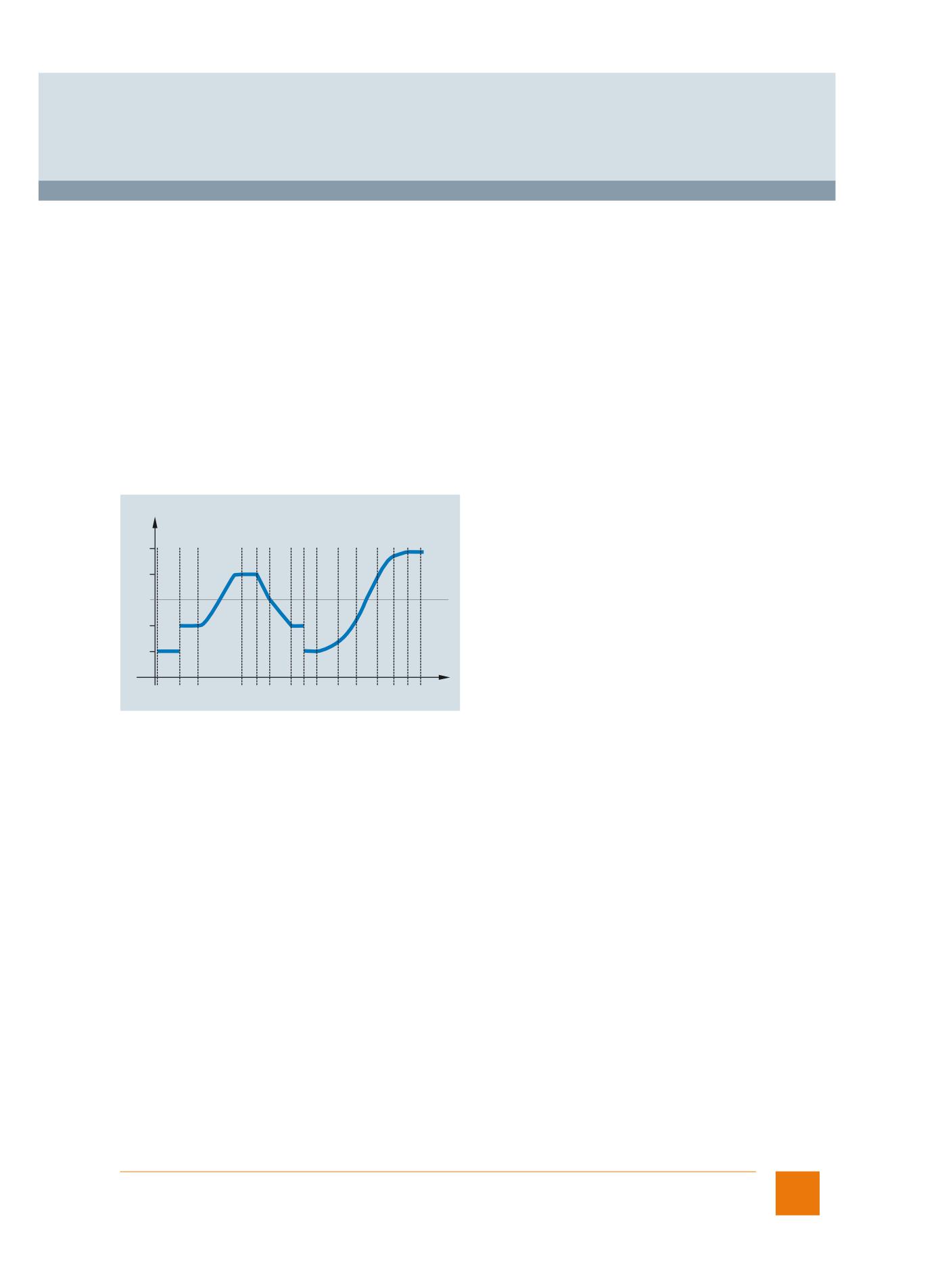
© Siemens AG 2017
Glossary
Functions and terms
SINUMERIK 840D sl
Feedrate interpolation (feed characteristic)
In accordance with DIN 66025, a constant feedrate over the part program block can be defined via address F. For a more flexible
definition of the feedrate profile, programming to DIN 66025 is expanded to include linear and cubic profiles over the path. The cubic
profiles can be programmed directly or as an interpolating spline.
This makes it possible, depending on the curvature of the workpiece to be machined, to program continually smooth velocity profiles,
which in turn allow jerk-free acceleration changes and thus the production of uniform workpiece surfaces.
You can program the following feedrate profiles:
• FNORM
Response according to DIN 66025 (default setting). An F value programmed in the CNC block is applied over the entire path of
the block, and is subsequently regarded as a fixed modal value.
• FLIN
An F value programmed in the block can be traversed linearly (rising or falling) over the path from the actual value at the beginning
of the block to the end of the block, and is subsequently regarded as a modal value.
• FCUB
The non-modally programmed F values (relative to the end of the block) are connected through a spline. The spline starts and
ends tangentially to the previous or following feedrate setting.
• FPO
The feedrate profile can also be programmed directly via a polynomial. The polynomial coefficients are specified analogous to
polynomial interpolation.
Feed-
rate
N N
N
13 14
5000
12
N4
N5
4000
N11
N3
N6
3000
N10
N2
N7
2000
N9
N1
N8
1000
Path
G_NC01_en_00131
Programming example: Feedrate interpolation
N1 Constant feedrate profile F1000: FNORM
N2 Abrupt setpoint velocity change F2000: FNORM
N3 Feedrate profile via polynomial : F = FPO (4000, 6000, -4000)
N4 Polynomial feedrate 4000 as modal value
N5 Linear feedrate profiles F3000: FLIN
N6 Linear feedrate 2000 as modal value
N7 Linear feedrate, as modal value
N8 Constant feedrate profile with abrupt acceleration change F1000: FNORM
N9 All subsequent F values are linked by splines F1400: FCUB
N13 Switch off spline profile
N14 FNORM
Polynomial interpolation
Feedrate override
The programmed velocity is overridden by the actual velocity setting via the machine control panel or by the PLC (0 % to 200 %).
In order for the cutting velocity along the contour to be kept constant, the feedrate calculation is referred to the operating point or
tool end point.
The feedrate can also be corrected by a programmable percentage factor (1 % to 200 %) in the machining program. This factor is
overlaid (multiplication) on the setting made at the machine control panel. The velocity setting from the PLC is axis-specific.
Follow-up mode
In follow-up mode, an axis/a spindle can be moved independently, while the actual value continues to be detected. The traversing
paths are updated in the display. Standstill, clamping and positioning monitoring functions are not effective in the follow-up mode.
Once follow-up mode is cancelled, reference-point approach of the axis does not have to be repeated.
Siemens NC 62 · 2017
31
© Siemens AG 2017
Glossary
Functions and terms
SINUMERIK 840D sl
Frame concept
Frame is the common term for a geometric expression describing an arithmetic operation, for example, translation or rotation.
For SINUMERIK CNCs, the frame in the CNC program transfers from one Cartesian coordinate system to another, and represents the
spatial description of the workpiece coordinate system.
The following are possible:
• Basic frames: Coordinate transformation from basic coordinate system BCS into basic zero system BZS
• Settable frames: Work offsets using G54 to G57/G505 to G599
• Programmable frames: Definition of workpiece coordinate system WCS
The frame concept makes it possible to transform Cartesian coordinate systems very simply by offsetting, rotating, scaling and
mirroring.
The following instructions are used to program these options:
• TRANS programmable work offset
• ROT rotation in space or in a plane
• ROTS rotation referred to the solid angle projected into the planes
• SCALE scaling (scale factor)
• MIRROR mirroring
• TOFRAME frame according to tool orientation
• TOROT rotary component of programmed frame
• PAROT frame for workpiece rotation (table rotation)
• MEAFRAME frame calculation from 3 measuring points in space (for measuring cycles).
The instructions can also be used several times within one program. Existing offsets can either be overwritten or new ones can be
added.
Additive frame instructions:
• ATRANS additive programmable work offset
• AROT additive rotation in space or in a plane
• ASCALE scale factor (multiplication)
• AMIRROR repeated mirroring
• AROTS additive rotation referred to the solid angle projected into the planes
If swivel-mounted tools or workpieces are available, machining can be implemented very flexibly, for example:
• By machining several sides of a workpiece by rotating and swiveling the machining plane
• By machining inclined surfaces using tool length and tool radius compensation
Friction compensation, Run MyCC /FRIC
Option; order code N67
Article No.: 6FC5800-0AN67-0YB0
Replaced by:
Optimized friction compensation
Restricted functionality of export versions:
Not possible.
32
Siemens NC 62 · 2017
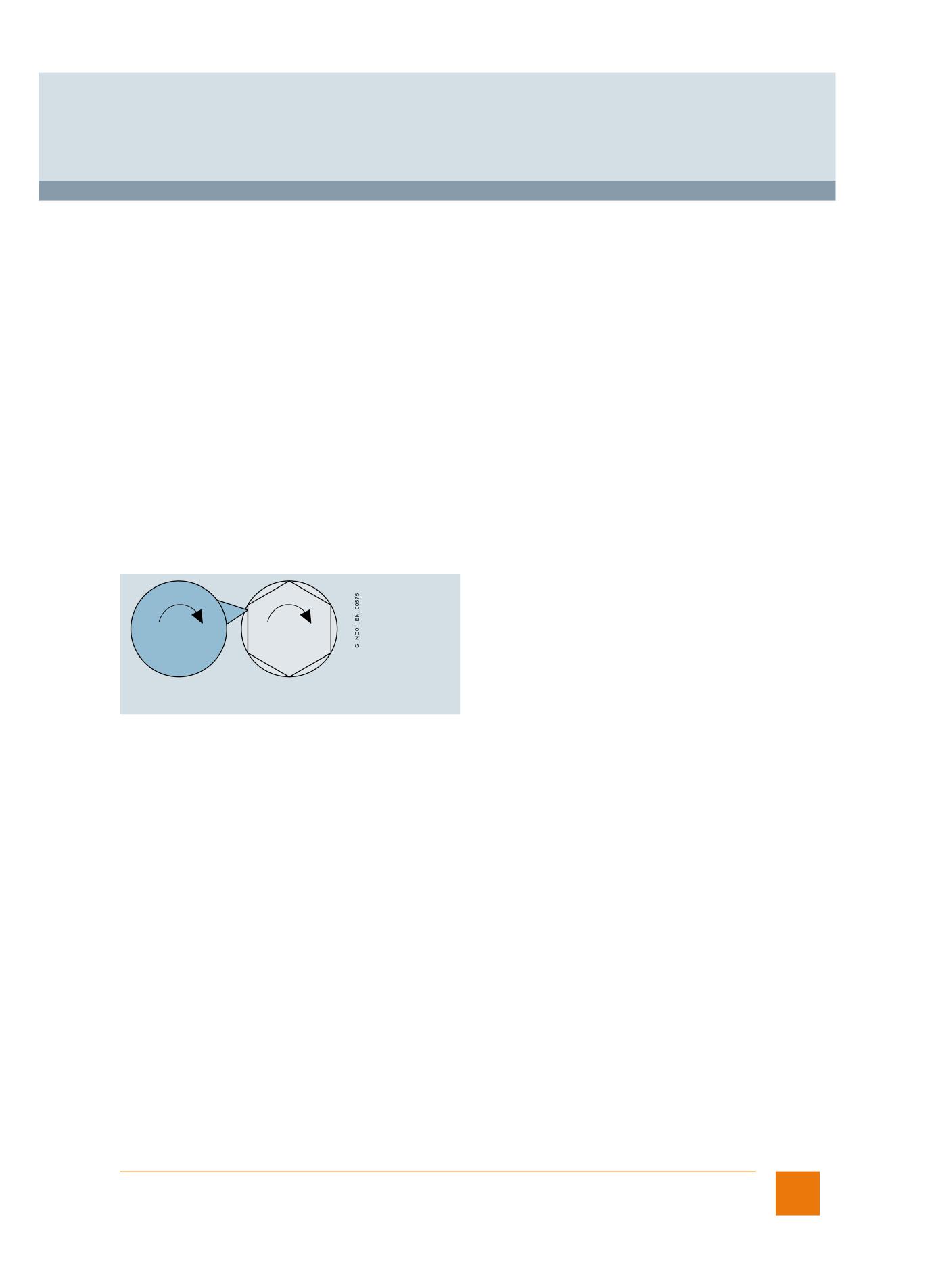
© Siemens AG 2017
Glossary
Functions and terms
SINUMERIK 840D sl
Generator operation
With the generator operation function, brief power outages can be buffered or power provided for retraction. To make this possible,
the energy stored during spindle rotation or axis movement is fed back into the DC link, following the same principle as that used by
generators.
Generic coupling
We offer 5 different performance levels for generic (general) coupling (CP) of axes/spindles. The functionality is scalable via the
number of leading axes to one following axis, via coupling characteristics ranging from simple functionality through to technological
innovations and via the simultaneously activatable coupling types.
The options CP-Static, CP-Basic, CP-Comfort and CP-Expert are available. These options can be combined as required. The number
of coupled objects actively in use at the same time is monitored, i.e. if multi-edge machining and synchronous spindle are not
simultaneously in use, for example, CP-Basic is sufficient. However, if these two functions need to be used simultaneously, CP-Static
will be required additionally (or, depending on the number of additional coupling functions, CP-Comfort).
Restricted functionality of export versions:
See the functional restrictions for each of the above-mentioned functions.
Generic coupling CP-Basic
Option; order code M72
Article No.: 6FC5800-0AM72-0YB0
• 4 axis pairs in simultaneous coupled motion and
• 1 × synchronous spindles/multi-edge turning and/or master value coupling/curve table interpolation and/or axial coupling in the
machine coordinate system
n2
n1
Spindle 1
Spindle 2
Restricted functionality of export versions:
The number of simultaneously interpolating axes is restricted to 4.
Generic coupling CP-Comfort
Option; order code M73
Article No.: 6FC5800-0AM73-0YB0
• 4 axis pairs in simultaneous coupled motion and
• 4 × synchronous spindles/multi-edge turning and/or master value coupling/curve table interpolation and/or axial coupling in the
machine coordinate system
Also:
• 1 × electronic gear for 3 leading axes
without curve table interpolation and without cascading
Restricted functionality of export versions:
The number of simultaneously interpolating axes is restricted to 4.
Electronic gear
Siemens NC 62 · 2017
33
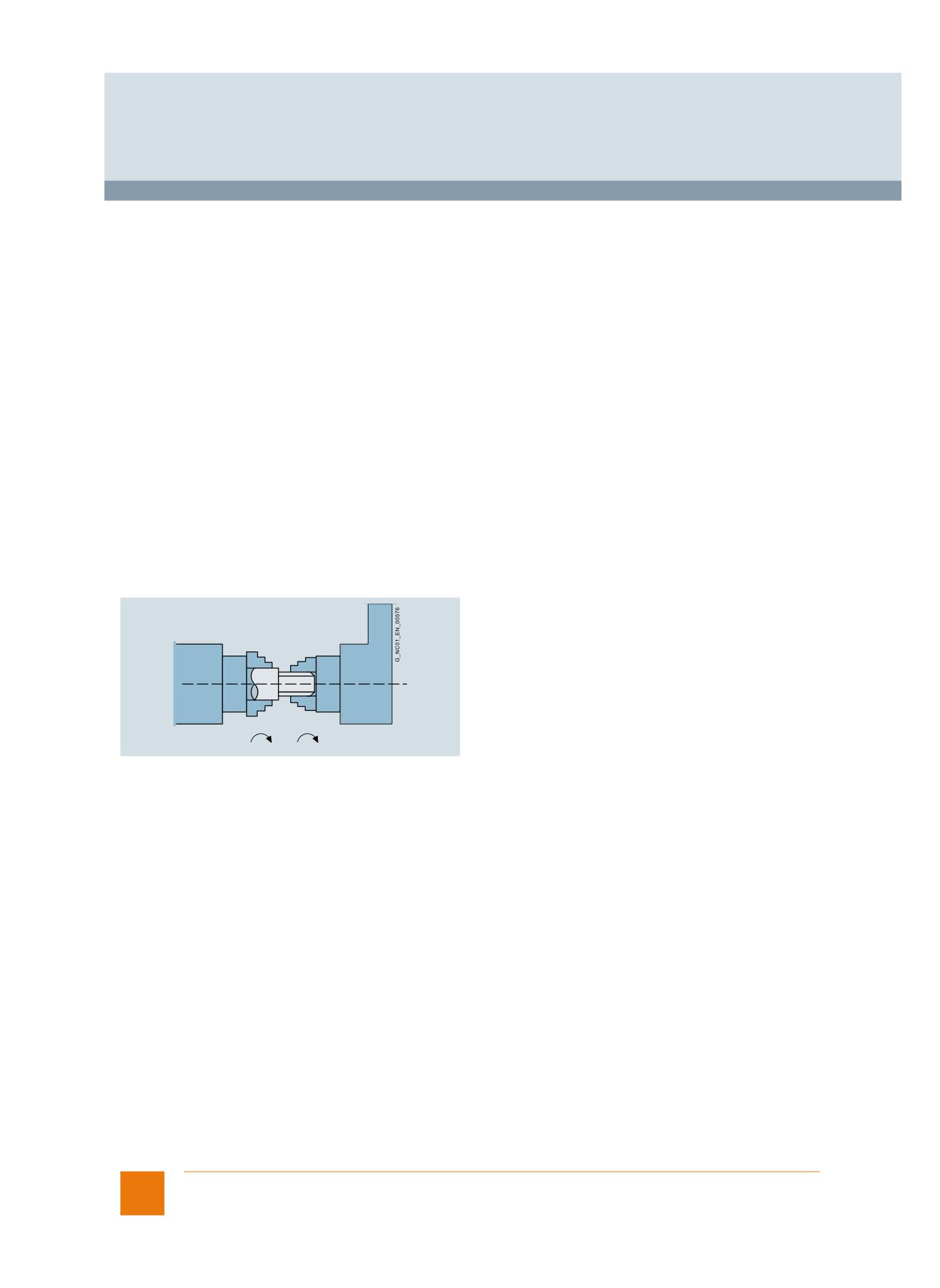
© Siemens AG 2017
Glossary
Functions and terms
SINUMERIK 840D sl
Generic coupling CP-Expert
Option; order code M74
Article No.: 6FC5800-0AM74-0YB0
• 8 axis pairs in simultaneous coupled motion and
• 8 × synchronous spindles/multi-edge turning and/or master value coupling/curve table interpolation and/or axial coupling in the
machine coordinate system
Also:
• 8 × electronic gear for 3 leading axes
without curve table interpolation and without cascading
• 5 × electronic gear for 5 leading axes
without curve table interpolation and without cascading
Restricted functionality of export versions:
The number of simultaneously interpolating axes is restricted to 4.
Electronic gear
Generic coupling CP-Standard
• Up to 4 × simple coupled motion with one leading axis and not used in synchronized actions
Generic coupling CP-Static
Option; order code M75
Article No.: 6FC5800-0AM75-0YB0
One simple synchronous spindle with coupling ratio 1:1, no multi-edge machining
n1
n2
Spindle 1
Spindle 2
Geometrically redundant axes, Run MyCC /GRED
Option; order code N73
Article No.: 6FC5800-0AN73-0YB0
SINUMERIK Integrate Run MyCC /GRED is a specific function and is not intended for general use.
Restricted functionality of export versions:
Not possible.
34
Siemens NC 62 · 2017
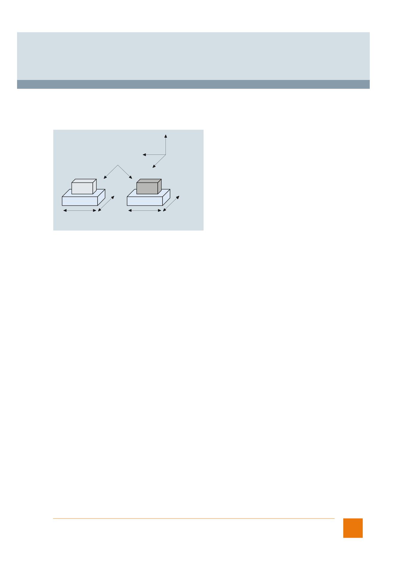
© Siemens AG 2017
Glossary
Functions and terms
SINUMERIK 840D sl
Geometry axes, switchable online in the CNC program
In the CNC, geometry axes form axis groupings per channel for the interpolation of path motion in space. Channel axes are assigned
to geometry axes via machine data.
With the switchable geometry axes function, it is possible, from the part program, to assemble the geometry axis grouping from other
channel axes. This makes problem-free operation of machine kinematics with parallel axes possible.
Z
Geometry axes
Online-switchable
X
channel axes
Y
Table 1
Table 2
Y1
Y2
X1
X2
G_NC01_en_00111
Geometry axes, switchable online
Geometry monitoring interface, Run MyCCI /GPM
Option; order code M83
Article No.: 6FC5800-0AM83-0YB0
SINUMERIK Integrate Run MyCC /GPM is a specific function and is not intended for general use.
Restricted functionality of export versions:
Not possible.
For general use, refer to:
Collision avoidance in real time
Grinding wheel surface speed, constant
Automatic conversion of the grinding wheel surface speed to a speed of rotation as a function of the current grinding wheel diameter.
This function can be active for several grinding wheels simultaneously in one CNC channel.
The grinding wheel surface speed is monitored.
A constant grinding wheel surface speed is not only useful when processing a part program in AUTO and MDI CNC operating
modes, but it can also be effective immediately after power-up of the CNC, on reset, and at the end of the part program, and remain
in force across all mode changes (depending on the machine data).
Siemens NC 62 · 2017
35
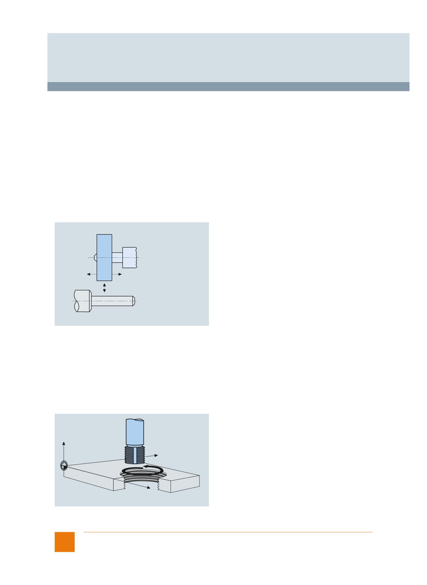
© Siemens AG 2017
Glossary
Functions and terms
SINUMERIK 840D sl
Handling package
Option; order code S31
Article No.: 6FC5800-0AS31-0YB0
For handling systems, the handling package offers a cost-effective solution:
• 3 additional axes
• 3 additional channels
• Transformation Handling
Requirement: Loadable compile cycle
• Synchronized actions stage 2
• No tool offsets and no spindles
Restricted functionality of export versions:
Not possible
Handwheel override
With the handwheel override function, an axis can be traversed or the velocity of an axis can be overridden. The function is
non-modal. At the same time, additional axes can be traversed simultaneously or using interpolation. The actual-value display is
continuously updated. Application: Grinding machines
Grinding wheel
Oscillation
Infeed via handwheel
Workpiece
G_NC01_en_00113
Handwheel override in AUTO CNC operating mode
Helical interpolation 2D+6
The helical interpolation function is ideal for machining internal and external threads using form milling tools and for milling lubrication
grooves.
The helix comprises 2 motions:
• Circular motion in one plane
• Linear motion perpendicular to this plane
The programmed feedrate F either refers only to the circular motion or to the total path velocity of the 3 CNC axes involved. In addition
to the 2 CNC axes performing circular interpolation, other linear motion can be performed synchronously. The programmed feed-
rate F refers to the axes specially selected in the program.
Z
Y
X
G_NC01_XX_00099
Helical interpolation: Thread milling with form cutter
Restricted functionality of export control versions:
Not possible.
36
Siemens NC 62 · 2017
© Siemens AG 2017
Glossary
Functions and terms
SINUMERIK 840D sl
High-speed CNC inputs/outputs
With the high-speed CNC inputs/outputs function, it is possible to read in or output signals in the position control/interpolation cycle.
High-speed CNC inputs/outputs can be used for machines, such as those used for grinding and laser machining, as well as in
SINUMERIK Safety Integrated.
Input signals are possible for the following:
• Several feedrate values in one block (caliper function)
The function allows modification of the feedrate through external signals. 6 digital inputs can be combined with 6 different feedrate
values in a CNC block. There is no feed interruption in this case. An additional input can be used to terminate the infeed (starting
a dwell time), and another input can be used to start immediate retraction. Depending on the input, the retraction of the infeed axis
(or axes) is initiated by a previously specified absolute value in the IPO cycle. The remaining distance-to-go is deleted.
• Several auxiliary functions in one block
Several auxiliary functions can be programmed in one CNC block. These functions are transferred to the PLC depending on a
comparison operation or an external signal.
• Axis-specific delete distance-to-go
The high-speed inputs cause conditional stopping and delete distance-to-go for the path or positioning axes.
• Program branches
The high-speed inputs make program branches within a user program possible.
• Rapid CNC start
Machining can be enabled conditionally in the CNC program depending on an external input.
• Analog calipers
Various feedrates, a dwell time and a retraction path can be activated depending on an external analog input (threshold values
are specified via machine data).
• Safety-related signals such as emergency stop
Output signals are possible for the following:
• Position switching signals
The position switching signals can be output with the position switching signals/cam controller function.
• Programmable outputs
• Analog value output
• Safety-related signals such as protective door interlock
Position switching signals/cam controller
HMI user memory, additional on CF card of NCU
Option; order code P12
Article No.: 6FC5800-0AP12-0YB0
The memory for part programs and expansions to the operator interface can be extended using the additional HMI user memory on
the CF card in systems without a SINUMERIK PCU.
With CNC software version 4.5 SP1 or higher (on an 8 GB CF card), the memory is extended by 6 GB.
CNC user memory, additional
Siemens NC 62 · 2017
37
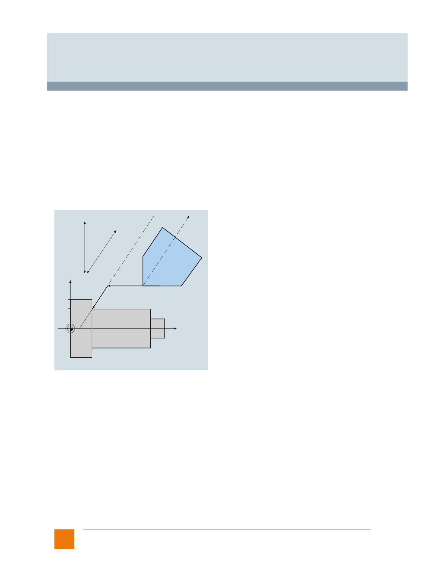
© Siemens AG 2017
Glossary
Functions and terms
SINUMERIK 840D sl
I/O interfacing via PROFIBUS DP and PROFINET
PROFIBUS DP represents the protocol profile for distributed I/Os. It enables high-speed cyclic communication. Advantages of
PROFIBUS DP: very short bus cycle times, high degree of availability, data integrity, and standard message frame structure.
Like PROFIBUS, PROFINET as a real-time bus system supports all I/Os.
PROFINET
Inclined axis
Option; order code M28
Article No.: 6FC5800-0AM28-0YB0
The inclined axis function is used for fixed-angle interpolation using an oblique infeed axis. This is used primarily in conjunction with
cylindrical grinding machines. The axes are programmed and displayed in the Cartesian coordinate system. Tool offsets and work
offsets are also entered in the Cartesian system and transformed to the real machine axes.
For oblique plunge-cutting with G05, it is necessary to program the start position with G07. In the JOG CNC operating mode, the
grinding wheel can be traversed either in the Cartesian coordinate system or in the direction of inclined axis U (selection via the
channel DB).
JOG "X"
JOG "U"
U
X
G07 X70 Z40 F4000
100
G05 X70 F100
70
W
40
0
Z
G_NC01_XX_00121
Oblique plunge-cut grinding: machine with non-Cartesian X axis (U)
38
Siemens NC 62 · 2017
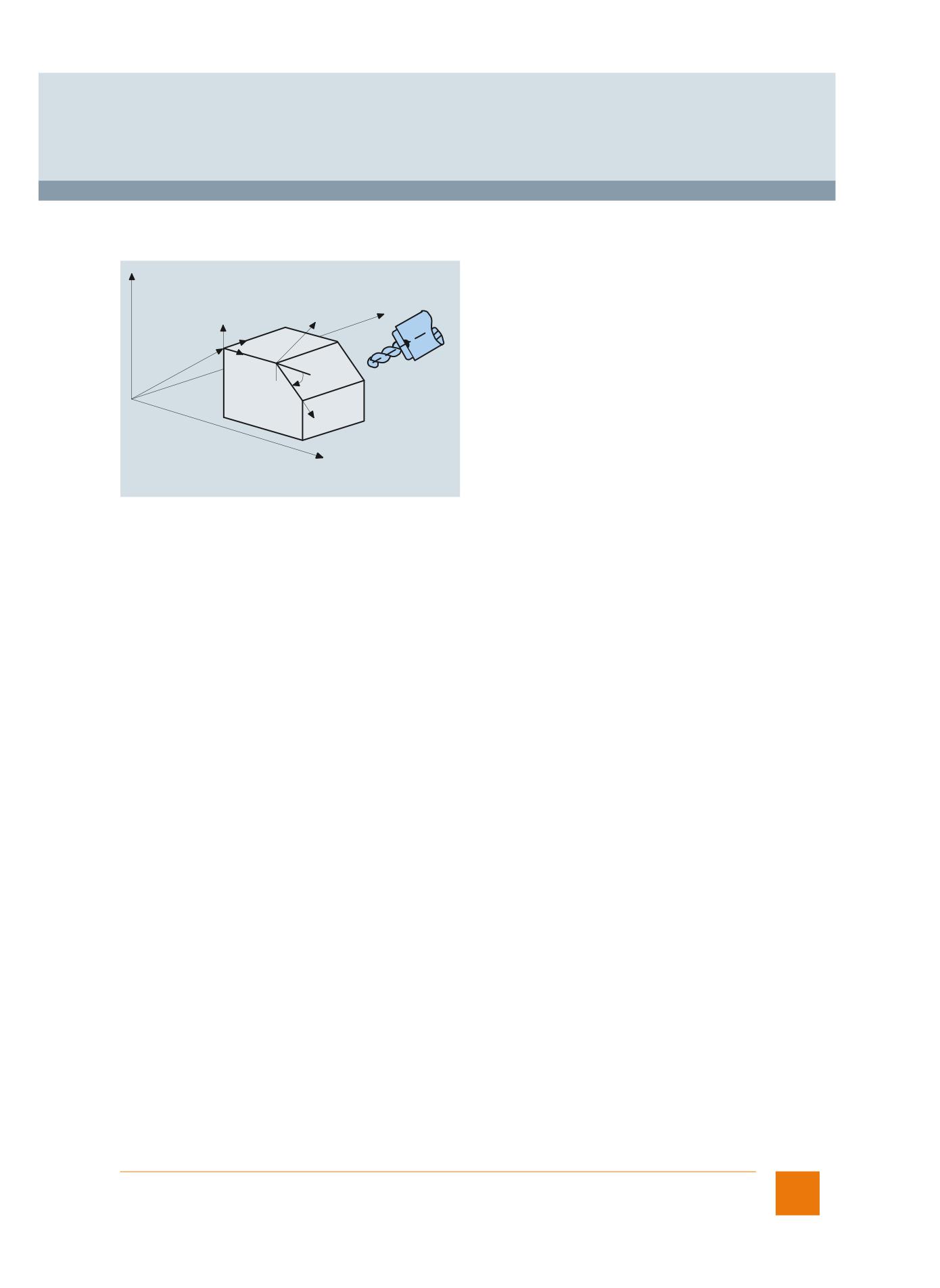
© Siemens AG 2017
Glossary
Functions and terms
SINUMERIK 840D sl
Inclined-surface machining with frames
Drilling and milling operations on workpiece surfaces that do not lie in the coordinate planes of the machine can be performed easily
with the aid of inclined-surface machining. The position of the inclined surface in space can be defined by coordinate system rotation.
Z Basis
Y Basis
Z
Z W
Y W
F
XW
+
X
X Basis
G_NC01_en_00122
Inclined-surface machining with frames
Frame concept
Industrial security
Industrial security includes all measures taken to plan, implement and monitor security in products and networks. The risk of hacking
and other security breaches increases as more and more machine networks are implemented via the Internet. Threats of this type
need to be warded off by appropriate precautions such as firewalls, encrypted connections, virus scanners, whitelisting and
organizational measures/policies.
Integrate CNC into production, Create MyInterface
Article No.: 6FC6000-7AC00-0AA8
With SINUMERIK Integrate Create MyInterface, it is possible to easily integrate SINUMERIK CNCs into the customer's manufacturing
network using defined interfaces. All essential machine data (such as status information, piece counts, alarms, messages, CNC pro-
grams, tool service life) can be exchanged between a central control system and the CNC, helping to reduce machine downtimes
and increase machine capacity utilization.
Integrate screens into the user interface
Use HMI applications, Run MyScreens
Integrated process monitoring, Run MyCC /IPM
Option; order code M70
Article No.: 6FC5800-0AM70-0YB0
SINUMERIK Integrate Run MyCC /IPM is a specific function and is not intended for general use.
Restricted functionality of export versions:
Not possible.
Siemens NC 62 · 2017
39
© Siemens AG 2017
Glossary
Functions and terms
SINUMERIK 840D sl
Integrated spindle monitor (S-Monitor)
Option; order code P55
Article No.: 6FC5800-0AP55-0YB0
The integrated spindle monitor (S-Monitor) is designed to allow fast, easy monitoring of additional information about the condition of
a WEISS motor spindle from the WEISS Spindle Sensor Module within SINUMERIK Operate:
• Clamping status and diagnostics
• Historical spindle data relating to speed, torque
• Motor temperature
• Bearing temperature
• Additional temperature sensor (KTY)
• Spindle operating time in various control modes
• Number of tool changes
• Logistics data of spindle
Integrated tool monitoring and diagnostics, IMD
The Integrated Monitoring and Diagnostics IMD is a software package with easy access to drive data (drive torque, encoder values,
setpoint speed, etc.) and program data (programmed path, programmed velocity, programmed interpolation type, etc.) directly in
the real-time part of the control. The function offers interfaces to the part program (language commands), to the PLC (fast I/O) and
to the HMI (files, GUD).
Integrated tool monitoring and diagnostics IMD BASE, Run MyCC /IMD
Option; order code N13
Article No.: 6FC5800-0AN13-0YB0
SINUMERIK Integrate Run MyCC /IMD integrated tool monitoring and diagnostics BASE supports the 'missing tool' monitoring
function as well as programming of a maximum permissible overload for a tool. The parameters are taught on program setup as for
the 'missing tool' monitoring function, and saved in the function-specific global user data (GUD). For all subsequent program runs,
the taught signals will be compared with the current ones and tool overload is avoided. Language command in the part program:
CC_START_TASK ("Fixed_Overload", …, ...).
SINUMERIK Integrate Run MyCC /IMD is also the prerequisite (interface) for customized add-ons in the field of process monitoring
and diagnostics. The openness in the real-time part of the SINUMERIK 840D sl is utilized, for example, by SINUMERIK Solution
Partners.
Integrated tool monitoring and diagnostics IMD LIGHT, Run MyCC IMD-L
Option; order code N12
Article No.: 6FC5800-0AN12-0YB0
SINUMERIK Integrate Run MyCC /IMD-L supports a 'missing tool' monitoring function within the IMD package. For this purpose, cuts
(transition from rapid traverse to creep feed) must be selected and parameterized (CC_START_TASK( "MissingTool", …, ...)) in the
part program. For example, select torque of spindle or torque of a specific axis.
The torque can be learned in an initial program run (teach-in).
In productive operation, the tool is assumed to be present when the actual signal is equal to the taught signal. If not, an individually
parameterized alarm response is triggered (RESET, CANCEL, Stop Spindle, Stop Axes, etc.).
Intermediate blocks for tool radius compensation
Traversing motion with selected tool offset can be interrupted by a limited number of intermediate blocks (block without axis motion
in the compensating plane). The permissible number of intermediate blocks can be set using system parameters.
Tool radius compensation
40
Siemens NC 62 · 2017
© Siemens AG 2017
Glossary
Functions and terms
SINUMERIK 840D sl
Internal/external drives
Internal drives are connected to an NCU/NX via DRIVE-CLiQ.
External drives are connected via PROFIBUS/PROFINET.
All internal and external drives are supported by SINUMERIK Operate:
• Parameter lists
• Diagnostics (alarms with time synchronization, traffic lights images, drive servicing)
• Series start-up
Third-party drives and SINAMICS G110/G120 are not supported by SINUMERIK Operate.
Axis/spindle
Interrupt routines with fast retraction from the contour
Option; order code M42
Article No.: 6FC5800-0AM42-0YB0
Interrupt routines are special subprograms which can be started on the basis of events (external signal) in the machining process.
Any part program block currently in progress is interrupted. The positions of the axes at the time of interruption are saved automati-
cally. It is also possible to save such things as the current states of G functions and the current offsets (SAVE mechanism) in buffer
storage, making it possible to resume the program at the point of interruption later without difficulty.
Four additional program levels are available for interrupt routines, that is, an interrupt routine can be started in the 8th program level
and lead as high as the 12th program level. An interrupt such as the switching of a high-speed CNC input can trigger a movement
via the special subprogram, which allows fast retraction of the tool from the workpiece contour currently being machined.
The retraction angle and the distance retracted can also be parameterized. An interrupt routine can also be executed following the
fast retraction.
Inverse-time feedrate
For CNC's, it is possible to program the time required to traverse the path of a block (rpm) instead of programming the feedrate for
the axis movement with G93. If the path lengths differ greatly from block to block, a new F value should be determined in every block
when using G93.
When machining with rotary axes, the feedrate can also be specified in degrees/revolution.
Involute interpolation
Option; order code M21
Article No.: 6FC5800-0AM21-0YB0
Using involute interpolation, it is possible to program a spiral contour with the shape of a circular involute in one CNC block instead
of many approximated individual blocks. The exact mathematical description of the contour enables a higher path velocity to be
achieved, together with a shorter machining time. Undesirable facets, which could result from coarse polygon functions, are thus
avoided.
Furthermore, it is unnecessary to define the end point for the involute interpolation exactly on the involute defined by the start point;
it is possible to enter a maximum permissible deviation using machine data.
Siemens NC 62 · 2017
41
© Siemens AG 2017
Glossary
Functions and terms
SINUMERIK 840D sl
Job list
This can be used to create a job list (loading list) for each workpiece.
This job list contains instructions on making the following preparations for executing part programs, even when multiple channels are
involved:
• Parallel setup (LOAD/COPY):
Load or copy main programs and subprograms and associated data such as initialization programs INI, R parameters RPA, user
data GUD, work offsets UFR, tool/magazine data TOA/TMA, setting data SEA, protection areas PRO, and sag/angularity CEC from
the PCU's hard disk into the CNC's work memory.
• Preparations for the CNC Start SELECT:
Select programs in different channels and make initial preparations for processing them
• Parallel clearing, reversed LOAD/COPY:
Remove/unload main programs, subprograms and associated data from the CNC's work memory to the hard disk
Users can also save their own templates for job lists. Following loading and job list selection, CNC start initiates the processing of all
programs and data required for workpiece production.
42
Siemens NC 62 · 2017

© Siemens AG 2017
Glossary
Functions and terms
SINUMERIK 840D sl
Laser switching signal, high-speed, Run MyCC /HSLC
Option; order code M38
Article No.: 6FC5800-0AM38-0YB0
For high-speed laser machining, e.g. of aperture plates, the laser is switched on and off automatically and with a very high positional
accuracy relating to the path. Under the prerequisite that all movements for which the laser must be switched off are made in rapid
traverse mode G0, it is possible to logically combine the switching signal for the laser with the rising or falling edge of G0. The laser
switching signal can also be coupled to an adjustable G1 feedrate threshold value, if required. To achieve the fastest possible
responses, the switching on and off of the digital laser signal is controlled by a hardware timer with microsecond precision depending
on the actual axis position. No programming measures are required for switching the laser itself on and off, as these procedures are
directly linked to the programmed G functions. It is only necessary to program a release with CC_FASTON (DIFF1, DIFF2) for the
path section in which the laser is switched on or off. Together with this release, the two offset values, which can offset the switching
on and off of the laser by a specific path differential in relation to the position setpoint are entered.
Leadscrew error compensation / measuring system error compensation
On SINUMERIK CNCs, interpolating compensation is divided into two categories:
• Leadscrew error compensation (LEC) or measuring system error compensation (MSEC) as axial compensation (basic axis and
compensating axis are always identical) and
• Sag error and angularity error compensation as cross-axis compensation (basic axis affects other compensation axis).
The principle of "indirect measuring" on CNC-controlled machines is based on the assumption that the leadscrew pitch is constant
at every point within the traversing range, so that the actual position of the axis can be derived from the position of the drive spindle
(ideal situation).
Tolerances in ball screw production, however, result in large dimensional deviations to a lesser or greater extent (referred to as
leadscrew error). These are complemented by dimensional deviations caused by the measuring system as well as its installation
tolerances on the machine (measuring system errors), plus any machine-dependent error sources. Because these dimensional
deviations directly affect the accuracy of workpiece machining, they must be compensated for by the relevant position-dependent
compensation values.
The compensation values are derived from measured error curves and entered in the CNC in the form of compensation tables during
commissioning. The relevant axis is compensated using linear interpolation between the intermediate points.
Leadscrew error compensation, bidirectional
Option; order code M54
Article No.: 6FC5800-0AM54-0YB0
Bidirectional compensation is an expansion of the leadscrew error compensation function (LEC) or the measuring system error
compensation function (MSEC). By contrast with the LEC and MSEC, bidirectional compensation acts in both directions.
Restricted functionality of export versions:
The correctable tolerance band is restricted to 1 mm (0.039 in).
Limit-switch monitoring
Preceding the emergency stop switch, hardware limit switches, which take the form of digital inputs controlled via the PLC interface,
limit the traversing range of the machine axes. Deceleration is realized either as rapid deceleration with setpoint zero or along a
braking characteristic. The axes must be retracted in the opposite direction in the JOG CNC operating mode.
Software limit switches precede the hardware limit switches, are not passed, and are not active until reference point approach has
been completed. Following preset, software limit switches are no longer effective. A second pair of plus/minus software limit switches
can be activated via the PLC.
Work area
limitation
1st
EMERGENCY
(geometric
SW limit switch
STOP
axes only)
2nd
switch
SW limit switch
Hardware
Mechanical
(can be activated via PLC)
limit switches
traversing limit
G_NC01_en_00110
Travel limits
Siemens NC 62 · 2017
43
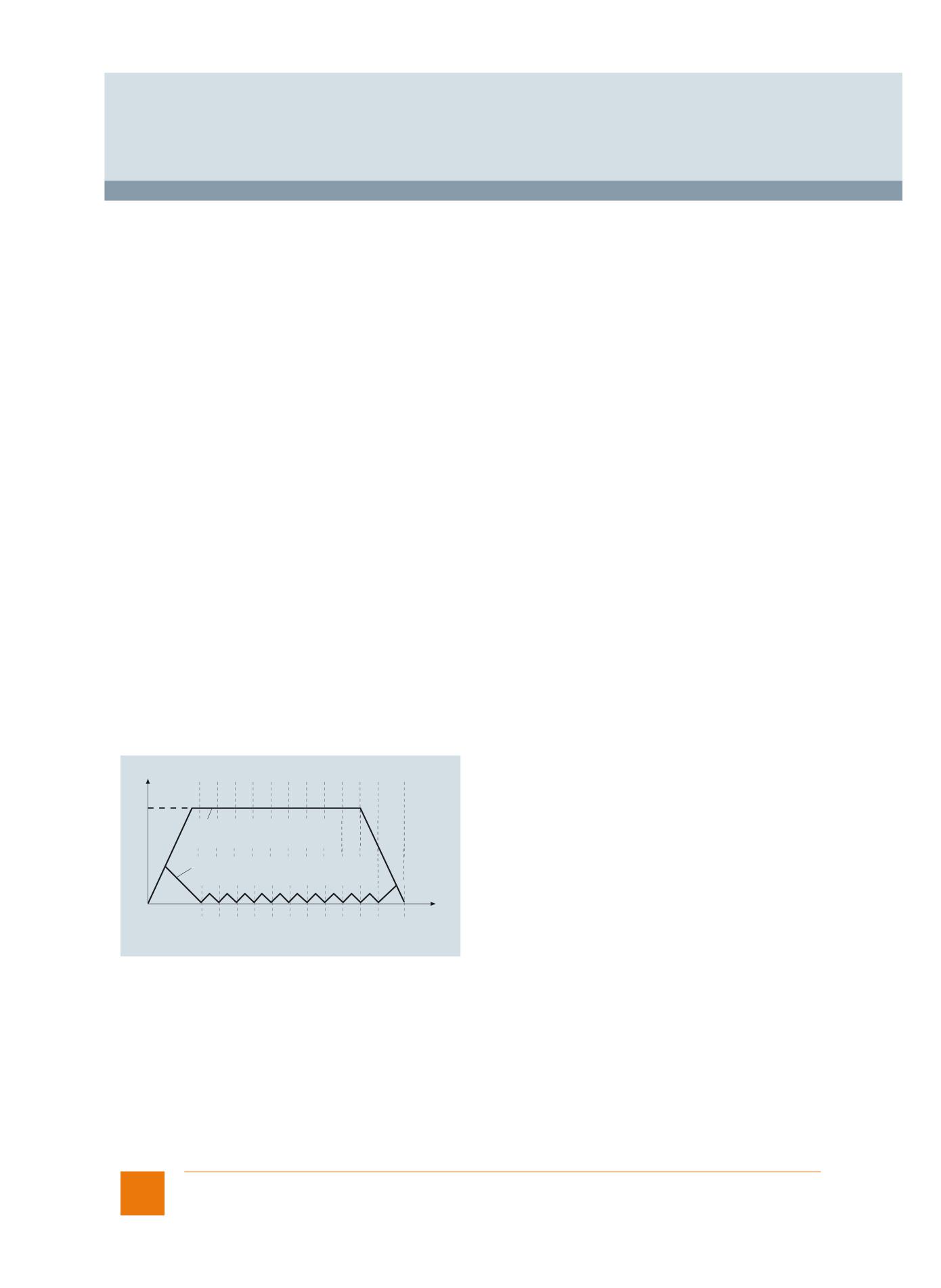
© Siemens AG 2017
Glossary
Functions and terms
SINUMERIK 840D sl
Linear interpolation
Linear interpolation is understood to be the CNC-internal calculation of points on a straight path between the programmed starting
and end points.
Restricted functionality of export control versions:
The number of simultaneously interpolating axes is restricted to 4.
Link control system
Create MyInterface
Master computer interface, Access MyMachine /OPC UA
Lock MyCycles
Option; order code P54
Article No.: 6FC5800-0AP54-0YB0
With SINUMERIK Integrate Lock MyCycles (cycle protection), cycles can be encrypted and then saved in the CNC where they are
protected. Execution in the CNC is possible without restrictions, but it is not possible to view the cycle. This protects the internal
company know-how.
The cycle can, however, be copied in an encrypted form. It can, therefore, be used on other machines. If use of the cycle on other
machines is to be prevented, it can be permanently linked to a particular CNC hardware unit by means of an addition to the program.
Lock MyPLC
The PLC machine program can be comprehensively protected by the know-how protection functionality provided by SIMATIC STEP 7
software version 5.5 SP3. This software guards technological knowledge against unauthorized access and modification. It prevents
the reverse engineering of machines, thus safeguarding the investments you have made.
Look Ahead
During the machining of complex contours, most of the resulting program blocks have very short paths with sharp transitions. If a
contour of this type is processed with a fixed programmed path velocity, an optimum result cannot be obtained. In short traversing
blocks with tangential block transitions, the drives cannot attain the required final velocity because of the short path distances.
Contours are rounded when traveling around corners.
The Look Ahead function is a means of optimizing the machining speed by looking ahead over a parameterizable number of travers-
ing blocks. For tangential block transitions, the axis is accelerated and decelerated beyond block boundaries, so that no drops in
velocity occur. For sharp path transitions, rounding of the contour is reduced to a programmable path dimension.
Feed
programmed
F1
G64: Look ahead
velocity control
G60: Constand velocity
phase
N1
N2
N3
N4
N5
N6
N7
N8
N9
N10
N11
N12
Block path
G_NC01_en_00159
Comparison of velocity response with exact stop G60 and
continuous-path mode G64 with look ahead for short distances.
Continuous-path mode with programmable rounding clearance
44
Siemens NC 62 · 2017
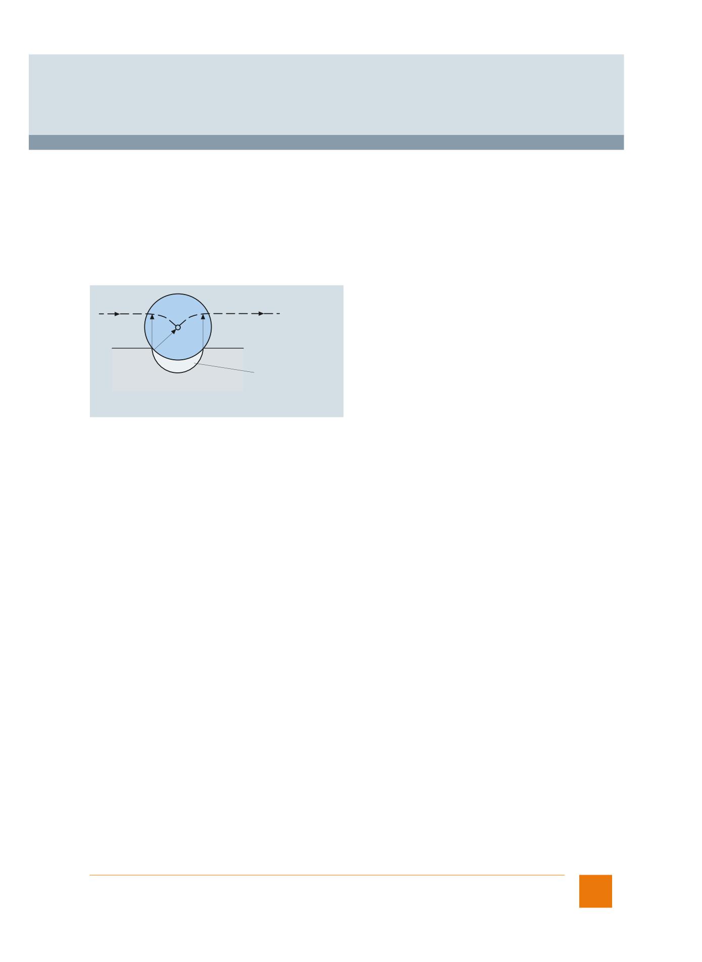
© Siemens AG 2017
Glossary
Functions and terms
SINUMERIK 840D sl
Look-ahead detection of contour violations
With collision detection CDON on and active tool radius compensation, the CNC monitors tool paths through look-ahead contour
calculation. Potential collisions are promptly identified in this way and actively prevented by the CNC.
For example, for an excessively large tool radius, the CNC identifies critical machine situations, which it compensates for by
modifying the tool paths.
• Bottleneck detection
Because the tool radius is too large to produce a narrow inside contour, the bottleneck is bypassed and an alarm output.
• Contour path shorter than tool radius
The tool bypasses the workpiece corner along a transition circle, then continues precisely on the programmed path.
• Tool radius too large for inside machining
In such cases, the contours are machined only as much as is possible without causing a contour violation.
R
Not machined
(but no contour
violation)
G_NC01_en_00130
Behavior when tool radius > circle radius
Siemens NC 62 · 2017
45
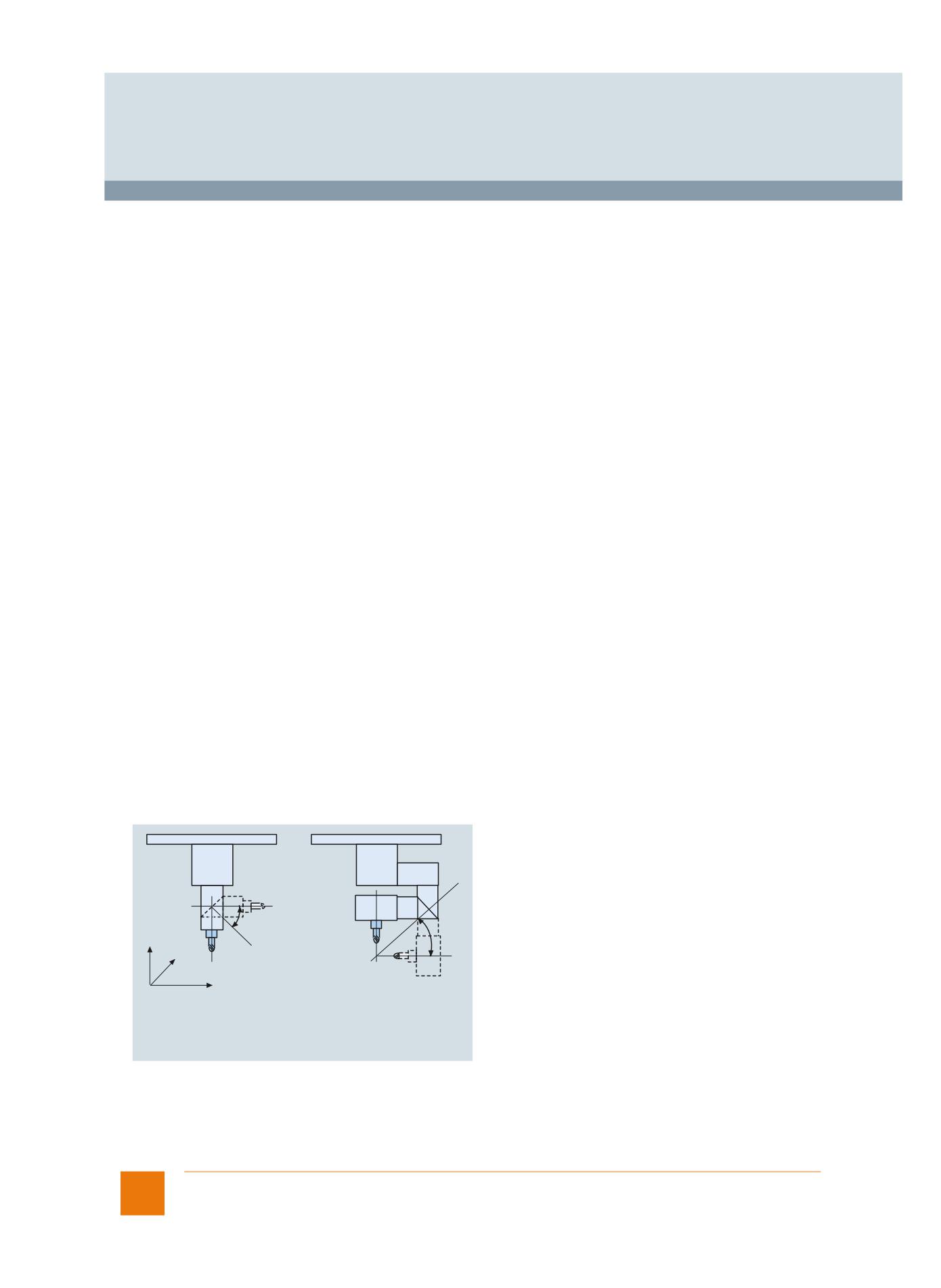
© Siemens AG 2017
Glossary
Functions and terms
SINUMERIK 840D sl
Machining channel
(Basic configuration: 1 machining channel)
Option; order codes C11 ... C19
Article No.: 6FC5800-0AC10-0YB0
Idle times can be shortened via a channel structure using parallel motion sequences, such as moving a loading gantry during
machining. A machining channel must be regarded as a separate CNC with decoding, block preparation and interpolation.
The channel structure makes it possible to process the individual channels' part programs simultaneously and asynchronously. The
relevant channel with the associated images is selected with the channel switchover button on the operator panel. Part programs
can then be chosen and started for that specific channel. Each possible channel can run in a separate mode group.
With the options with order codes C11 ... C19, the number can be increased to up to 10 machining channels.
Mode group
Machining package 5 axes
(Basic configuration: 3 axes/spindles)
Option; order code M30
Article No.: 6FC5800-0AM30-0YB0
With the machining package 5 axes, 5-axis machining tasks, such as the milling of free-form surfaces, can be simply implemented.
To this end, the machining package 5 axes provides the following functions:
• 5-axis transformation with tool orientation TRAORI
In 5-axis machining, geometric axes X/Y/Z are supplemented by additional axes such as rotary axes for swiveling the tool. The
machining task can be completely defined in Cartesian spatial coordinates with Cartesian position and orientation. The path vector
is converted in the control into the machine axes, including position and orientation, via 5-axis transformation.
• 5-axis tool length compensation for 5-axis machining
When machining with the 4th/5th axis, the lengths of the selected tool are automatically included and compensated in the axis
movement.
• Oriented tool retraction
If machining is interrupted because of tool breakage, for example, a program command can be used to carry out defined, oriented
tool retraction.
• Tool-oriented RTCP
With the remote tool center point RTCP function, the tool swivel axes can be positioned in the manual mode, as long as there is
compliance with the tool center point marked by the tool tip. The RTCP function simplifies the inclusion of program interpolation
points in manual mode with orientation of the tool.
• Cardan milling head/nutating head
Requirements: Machining package 5 axes with 5-axis transformation.
Using a cardan milling head in conjunction with the Nutating head function, it is possible to machine outside contours of spatially
formed parts at high feedrates. To do this, the CNC performs a 5-axis transformation. 3 translatory main axes X/Y/Z determine the
tool operating point; 2 rotary axes, one of which is an inclined axis (angle can be set in the machine data), permit virtually any
orientation in the working area. Version 1 and version 2 of the cardan milling heads are supported. In the case of version 2, the
position of the operating point does not change when the tool is swiveled; the compensating movements required for orientation
changes are minimal. Includes multi-axis interpolation (> 4 interpolating axes). The machining package 5 axes does not include
any additional axes/spindles which might be required.
A'
j
C
A'
C
Z Y
X
Nutating head
Nutating head
version 1
version 2
G_NC01_en_00106
Cardan milling head
Restricted functionality of export versions:
Not possible.
Multi-axis interpolation (> 4 interpolating axes)
Axis/spindle
46
Siemens NC 62 · 2017
© Siemens AG 2017
Glossary
Functions and terms
SINUMERIK 840D sl
Machining package 5 axes, additional function 7th axis
Option; order code S01
Article No.: 6FC5800-0AS01-0YB0
In combination with the machining package 5 axes or SINUMERIK MDynamics 5 axes, this option supports 7-axis interpolation. This
means that redundant rotation of a workpiece is possible in the work space, with 5th/6th axis tool kinematics active at the same time.
Application example: Fiber placement machines in the aerospace industry.
Restricted functionality of export versions:
Not possible.
Machining with robot, Run MyRobot /Machining
Option; order code P73
Article No.: 6FC5800-0AP73-0YB0
SINUMERIK Integrate Run MyRobot /Machining includes the options:
• Run MyCC /RODI (communication)
• Multi-axis interpolation (> 4 interpolating axes)
• Run MyHMI /3GL (for diagnostics)
SINUMERIK Integrate Run MyRobot /Machining allows a KUKA robot to be utilized, for example, as a milling robot, in combination
with a SINUMERIK 840D sl as the CNC. SINUMERIK Integrate Run MyRobot /Machining includes all the options required for this
purpose.
Communication interface to a robot, Run MyCC /RODI
Multi-axis interpolation (> 4 interpolating axes)
Use HMI applications, Run MyHMI /3GL
Restricted functionality of export versions:
Not possible.
Magnetic cogging torque compensation, Run MyCC /COCO
Option; order code N46
Article No.: 6FC5800-0AN46-0YB0
This compensation function is used particularly for electric direct drives where it is necessary to reduce the torque ripple at low
speeds in order to an obtain a better machining quality.
Restricted functionality of export versions:
Not possible.
Main program call from main program and subprogram
If machining operations recur frequently, it is advisable to store them in a subprogram. The subprogram is called from a main program
(number of passes 9999). Eleven subprogram levels (including 3 levels for interrupt routines) are possible in a main program.
A main program can also be called from within another main program or subprogram.
Manage MyPrograms
Article No.: 6FC5864-1AP41-0YB0
SINUMERIK Integrate Manage MyPrograms provides a central system of management and archiving for CNC programs and auto-
matic backup of SINUMERIK CNC data. For example, CNC programs can simply be transferred from Teamcenter. The advantage of
this feature is that it supports simple, centralized organization of CNC data into which CNC programmers can be integrated, as well
as fast access to CNC programs via networks.
It can be linked into the SINUMERIK Operate user interface without requiring the addition of supplementary external equipment on
the CNC.
Manage MyTools
Article No.: 6FC5864-2AP41-0YB0
SINUMERIK Integrate Manage MyTools provides users with a comprehensive overview of actual tool data including statistics and
planning for the entire production process. It supports a variety of different code carrier systems.
It offers the advantage of a closed tool data circuit - from procurement to use of the tool (procurement > tool setting > loading >
setup). It illuminates potential for rationalization, e.g. achieved by cost cutting, optimization and availability.
Siemens NC 62 · 2017
47
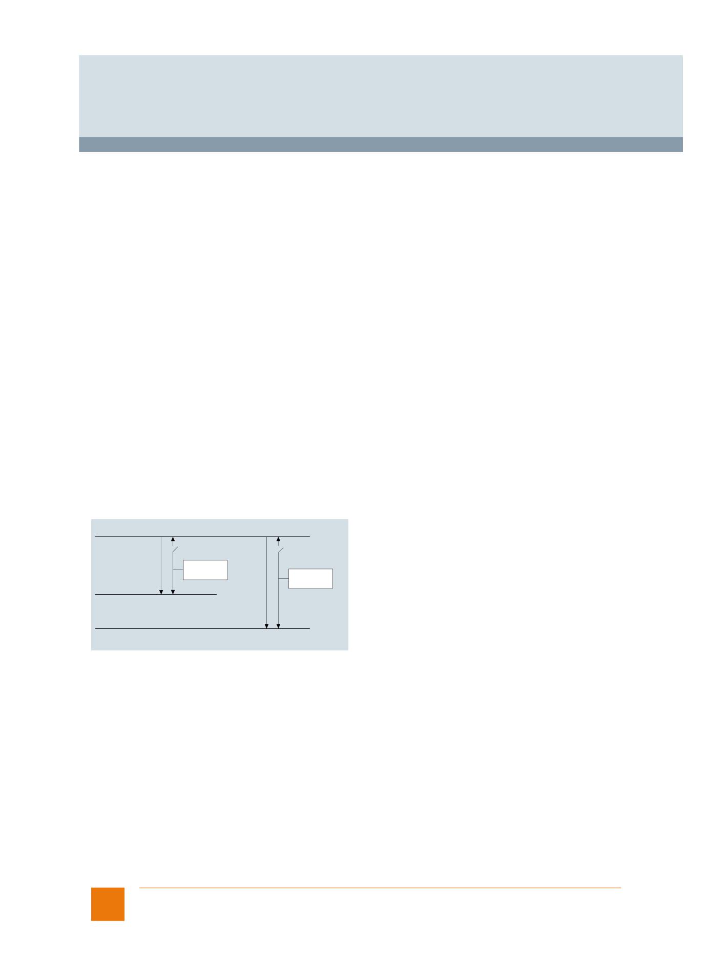
© Siemens AG 2017
Glossary
Functions and terms
SINUMERIK 840D sl
Manual machine
We offer the manual machine function for beginners switching over from conventional machines, but also for experienced CNC
machine operators who often only use individual machining steps. The MANUAL basic screen is displayed immediately after booting
the machine offering the direct machining options without having to create a part program.
ShopTurn/ShopMill
Master computer interface, Access MyMachine /OPC UA
Option; order code P67
Article No.: 6FC5800-0AP67-0YB0
The SINUMERIK Integrate Access MyMachine /OPC UA function enables the communication channel for the OPC UA server on the
SINUMERIK PCU or the SINUMERIK NCU. The OPC UA data access method permits the reading and writing of CNC and PLC
variables. OPC Unified Architecture OPC UA is a standardized, industrial communication protocol for the access to control data, e.g.
by control systems.
Master/slave for drives
Option; order code M03
Article No.: 6FC5800-0AM03-0YB0
The master/slave for drives function is required when 2 electrical drives are mechanically linked to an axis. With this link, a torque
controller ensures that both drives produce the exact same amount of torque, so that the motors do not work in opposition. In order
to attain tensioning between the master and slave drives, a tension torque specifiable via machine data can be applied to the torque
controller.
Application examples:
• Increasing the power rating and (occasional) mechanical linking of drives
• Drive with 2 motors that operate on a gear rack
• Remachining of wheel sets for rail vehicles
• Zero backlash reversing of mutually tensioned drives
An axis can also be a leading axis for multiple links.
Master
Axis 1
Link 1
Link 2
Speed
Torque
setpoint link
controller
Torque
controller
Slave
Axis 2
Speed
setpoint link
Slave
Axis 3
G_NC01_EN_00116
Axis 1 is simultaneously the master axis for axis 2 and axis 3
48
Siemens NC 62 · 2017
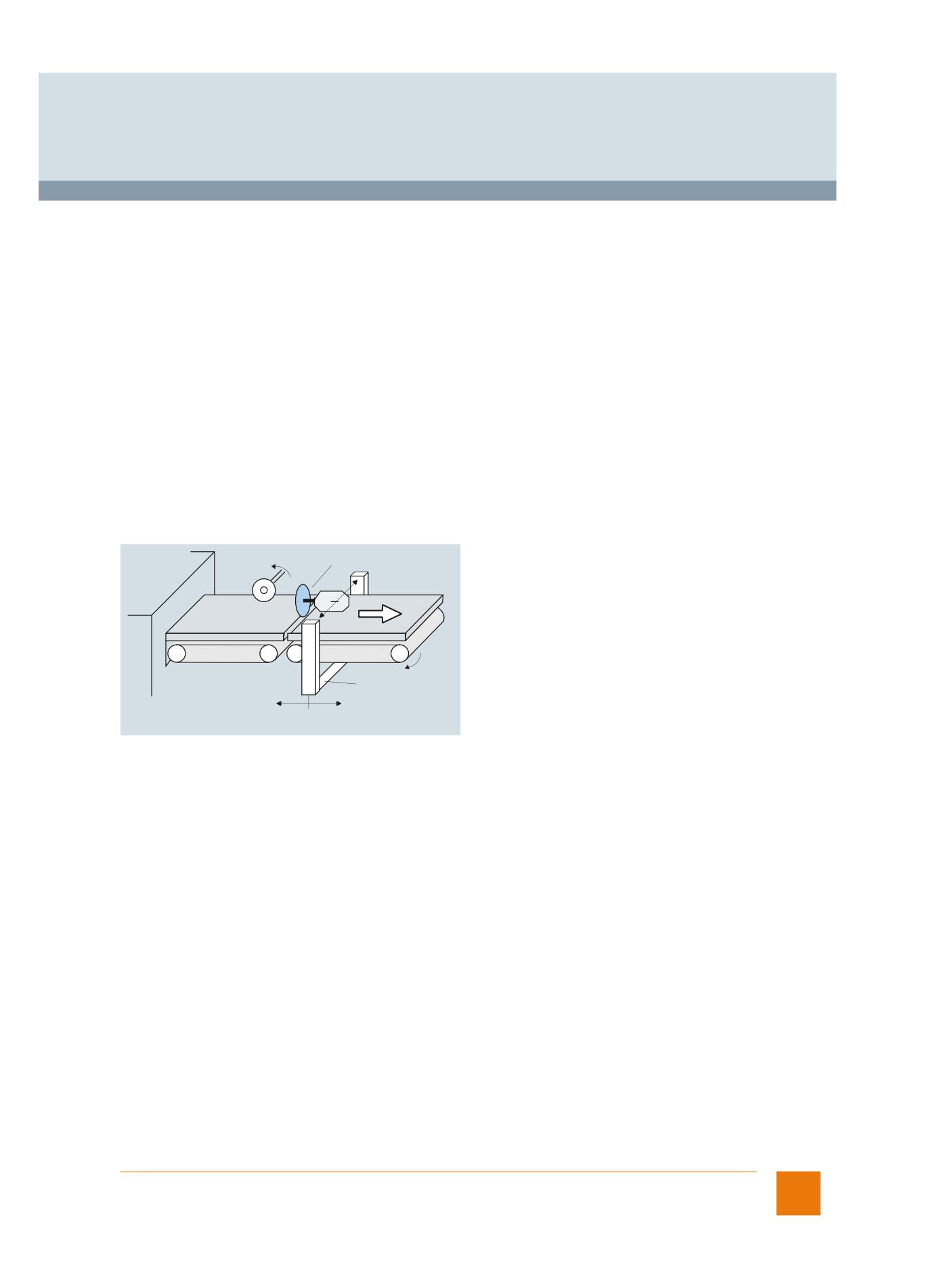
© Siemens AG 2017
Glossary
Functions and terms
SINUMERIK 840D sl
Master-value coupling and curve table interpolation
For special technologies (presses, transfer lines, printing machines, etc.), the replacement of mechanical, cyclic transport tasks with
electronic functionality in AUTOMATIC mode requires constant coupling and decoupling functions between leading and following
axes. To this end, the synchronous spindle function has been expanded to include the master value coupling function, which makes
it possible for linear guide and following axes to be coupled via curve tables in the CNC program.
Any function relations between axis positions can be approximated. Soft coupling avoids the sudden change in velocity that occurs
when the guide axis is activated. Offsets (e.g. 12°), scalings (e.g. 1.00023) and mirroring using frame instructions are possible.
Electronic curve table interpolation replaces the cam disks that were once required for the computerized numerical control of cyclic
machines. Complex sequences of motion can be easily defined using familiar CNC language elements. The external reference
variable (e.g. "line shaft") is formed by the CNC's master value. The functional relation between leading and following axis can be
subdivided into segments of the leading axis (curve segments). In these curve segments, the link between master value and
following value is described using mathematical functions (normally through 3rd degree polynomials).
Cyclic machines are distinguished by constantly repeated cyclic operations with high throughput and high productivity in machining,
transport, packaging and parts handling (for example, packaging machines, presses, woodworking machines, printing machines).
With the SINUMERIK CNC, technological functions such as synchronism, electronic transfer and positioning for cyclic machines can
be implemented. Mechanical systems (line shaft, gearing, cam disks, couplings and cams) are replaced by an electronic solution
(master value coupling, curve tables, synchronized actions, and electronic cams).
In addition, the electronic functionality permits fast, axis-specific optimization, high-speed phase and path compensation, fast re-
sponses to faulty or missing parts, and fast synchronization and resynchronization, as well as decoupling from the leading axis and
execution of autonomous movements. Axis cycles and synchronization calculations are carried out in the IPO cycle.
Measuring from synchronized actions, for example, is used for detecting edges on continuous workpieces and for measuring print
marks (on continuous film, for example).
Top roller
Saw
+
+
+
+
Saw carriage
X
G_NC01_en_00114
Example for cyclic machines: Flying saw
Restricted functionality of export control versions:
The number of simultaneously traversing axes is restricted to 4.
Generic coupling
Measuring stage 2
Synchronous spindles, multi-edge turning
Measure kinematics
Option; order code P18
Article No.: 6FC5800-0AP18-0YB0
The Measure kinematics function supports the calibration of kinematic structures of 5-axis machines.
The SINUMERIK 840D sl is able to determine the parameters of kinematic transformations of the digitally or manually alignable rotary
axes quickly and automatically.
The function is ideal for initial startup, because a dimension drawing of the machine is not required. The function can also be used
for regular checking of the production process where high precision is required.
Siemens NC 62 · 2017
49
© Siemens AG 2017
Glossary
Functions and terms
SINUMERIK 840D sl
Measuring cycles
Option; order code P28
Article No.: 6FC5800-0AP28-0YB0
In the case of tool measuring, the loaded tool (typically in the revolver on turning machines) is moved towards the probe, which is
either in a fixed position or swiveled into the working range by a mechanical device.
The automatically derived tool geometry is entered in the relevant tool offset data record.
In the case of workpiece measuring, a probe is moved towards the clamped workpiece like a tool. The flexible structure of the
measuring cycles means that it is possible to handle virtually every measuring task associated with turning or milling.
The flying measurement principle is used in SINUMERIK CNCs. The advantage of this principle is that the probe signal is processed
directly in the CNC. The measuring parameters and the results of the measurements are output extremely clearly in separate
displays, which are either automatically deselected at the end of the cycle or can be acknowledged when starting the CNC.
The result of the workpiece measurement can either include automatic offset of the zero point or a correction of the tool wear by the
difference between the actual value and the setpoint. The measurement results can be logged in a file.
Siemens measuring cycles offer a standard log, which can be freely configured by the user.
In order to measure tool and workpiece dimensions, a touch-trigger probe is required that supplies a constant signal (rather than a
pulse) when deflected. The probe should switch without any bounce, and mechanical adjustment may be necessary. Multidirectional
probes can be used for all tool and workpiece measurements on turning and milling machines. Bidirectional probes are treated like
a mono probe for workpiece measurements on milling and machining centers, but are not suitable for tool measurements.
Monodirectional probes can be used on milling machines and machining centers with slight restrictions in workpiece measurements,
but are not suitable for tool measurements or for workpiece measurements on turning machines.
Milling measurement:
• Corner/right-angled corner/any corner
• Calibrate probe: length/radius in ring/radius at edge/calibrate on sphere
• Hole/rectangular pocket
• Hole/inner circle segment
• Edge distance - slot/web
• Edge distance - set edge
• Edge distance - align edge
• Circular/rectangular spigot
• Spigot/outer circle segment
• Measure 3D - align plane
• Measure 3D - 1 sphere/3 spheres
• Measure tools
• Measure tools - calibrate tool probe
Turning measurement:
• Calibrate probe - length/radius at surface/radius in slot
• Inner/outer diameter
• Measure tools - turning tools/milling tools/drills
• Measure tools - calibrate tool probe
50
Siemens NC 62 · 2017
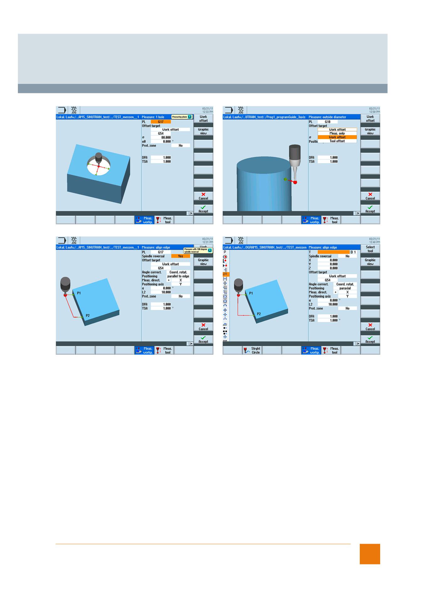
© Siemens AG 2017
Glossary
Functions and terms
SINUMERIK 840D sl
The use of high-precision probes such as those from Renishaw's Rengage range is recommended.
Example: Measuring a hole (programGUIDE)
Example: Measuring an outer diameter (programGUIDE)
Example: Align edge (programGUIDE)
Example: Align edge (ShopMill)
Measuring functions/measuring cycles
Measuring functions can execute either channel-specifically including all axes programmed in the measuring block as well as axially
from the part program or from synchronized actions beyond CNC block limits. Measuring cycles are subprograms for implementing
specific measuring tasks on tools or workpieces.
They are easy to use and simply require the input of values in predefined parameters.
• Measuring in JOG
• 2 probes can be connected simultaneously
• Measurement in space with frame
• Adaptable measuring modes with/without deletion of distance-to-go
• Display and logging of measuring parameters and results (with measuring cycles)
• Results can be read in the machine or workpiece coordinate system
• Cyclic measurement with synchronized actions parallel to workpiece machining
With the advantages of the measuring functions and measuring cycles, the machining accuracy is assured, unproductive time is
reduced, sources of error are eliminated and further production processes are automated.
Siemens NC 62 · 2017
51
© Siemens AG 2017
Glossary
Functions and terms
SINUMERIK 840D sl
Measuring inputs, expanded (16) for axial measurements, Run MyCC /PROX
Option; order code N57
Article No.: 6FC5800-0AN57-0YB0
SINUMERIK Integrate Run MyCC /PROX is a specific function and is not intended for general use.
Restricted functionality of export versions:
Not possible.
Measuring stage 1
Up to 2 switching probes can be connected simultaneously to the CNC. In the case of channel-specific measuring, the measuring
process for a CNC channel is always activated from the part program running in the relevant channel. All of the axes programmed
in the measuring block take part in the measuring process.
It is possible to program a trigger event (rising or falling edge) and a measuring mode with or without deletion of distance-to-go for
each measuring process. The results of measurements can be read in the part program or with synchronized actions in both the
machine and the workpiece coordinate system. You can test the deflection of the probe by scanning a variable and outputting it to
the PLC interface and deriving responses in the part program.
Measuring stage 2 (option, order code M32) provides expanded functionality (for example for axial measuring, evaluation of up to
4 trigger events, and cyclic measuring).
Measuring stage 2
Option; order code M32
Article No.: 6FC5800-0AM32-0YB0
While the measuring function in motion blocks in the part program is limited to one block, you can activate measuring functions from
synchronized actions at any time, independent of the part program. The measuring events can be assigned to the axes in the CNC
block. In the case of simultaneous measuring, up to 4 trigger events can be evaluated per position control cycle. Measured values
are read as a function of the 3 parameters: probe, axis and measuring edge.
In the case of continuous (cyclic) measuring, the measurement results are written to a FIFO variable. Endless measuring can be
achieved by reading out the FIFO values cyclically. Measurement results can be logged in the form of a file. The measuring cycles
(option, order code P28) contain a standard log, which can be configured as the user wishes.
Measuring system error compensation
Leadscrew error compensation/measuring system error compensation
Measuring systems 1 and 2, selectable
For special applications, 2 encoders can be assigned to one axis, such as for a direct measuring system for the machining process
with high demands on accuracy, and an indirect measuring system for high-speed positioning tasks. The switchover between
measuring systems 1 and 2 is performed via the PLC.
Metal spinning protection area, Run MyCC /MSPZ
Option; order code N42
Article No.: 6FC5800-0AN42-0YB0
SINUMERIK Integrate Run MyCC /MSPZ is a specific function and is not intended for general use.
Restricted functionality of export versions:
Not possible.
52
Siemens NC 62 · 2017
© Siemens AG 2017
Glossary
Functions and terms
SINUMERIK 840D sl
Metric/inch dimensions
Depending on the measuring system used in the production drawing, it is possible to program workpiece-related geometrical data
in either metric units (G71) or inches (G70). The CNC is set to a basic system regardless of the dimension system that has been
programmed.
You can enter the following geometrical data directly and let the CNC convert them into the other dimension system (examples):
• Position data X, Y, Z, etc.
• Interpolation parameters I, J, K and circle radius CR
• Pitch
• Programmable work offset (TRANS)
• Polar radius RP
With the G700/G710 programming expansion, all feedrates are also interpreted in the programmed measuring system (inch/min or
mm/min). In the Machine operating area, the operator can switch back and forth between inch and metric dimensions using a softkey.
Milling technology package SINUMERIK MDynamics 3 axes
Option; order code S32
Article No.: 6FC5800-0AS32-0YB0
SINUMERIK MDynamics 3 axes contains the options:
ShopTurn/ShopMill
Residual material detection and machining for contour pockets and stock removal
3D simulation 1 (finished part)
Simultaneous recording (real-time simulation of the current machining operation)
Advanced Surface
Spline interpolation (A, B and C splines)
TRANSMIT/cylinder surface transformation
Measuring cycles
Milling technology package SINUMERIK MDynamics 5 axes
Option; order code S33
Article No.: 6FC5800-0AS33-0YB0
SINUMERIK MDynamics 5 axes contains the options:
ShopTurn/ShopMill
Residual material detection and machining for contour pockets and stock removal
3D simulation 1 (finished part)
Simultaneous recording (real-time simulation of the current machining operation)
Advanced Surface
Spline interpolation (A, B and C splines)
TRANSMIT/cylinder surface transformation
Measuring cycles
Machining package 5 axes
3D tool radius compensation
Measure kinematics
Restricted functionality of export versions:
Not possible.
Mode group
(Basic configuration: 1 mode group)
Option; order codes C01 ... C09
Article No.: 6FC5800-0AC00-0YB0
A mode group combines CNC channels with axes and spindles to form a machining unit. A mode group contains channels that must
always operate in the same CNC operating mode at the same time during the machining sequence. Within a mode group, every axis
can be programmed in every channel. A mode group can be regarded as an independent, multi-channel CNC. The number can be
increased to include up to 10 mode groups using the option.
Siemens NC 62 · 2017
53